EP3623130A1 - Machine and method for compacting a powder material - Google Patents
Machine and method for compacting a powder material Download PDFInfo
- Publication number
- EP3623130A1 EP3623130A1 EP19197157.1A EP19197157A EP3623130A1 EP 3623130 A1 EP3623130 A1 EP 3623130A1 EP 19197157 A EP19197157 A EP 19197157A EP 3623130 A1 EP3623130 A1 EP 3623130A1
- Authority
- EP
- European Patent Office
- Prior art keywords
- powder material
- conveyor belt
- designed
- assembly
- compacted
- Prior art date
- Legal status (The legal status is an assumption and is not a legal conclusion. Google has not performed a legal analysis and makes no representation as to the accuracy of the status listed.)
- Granted
Links
Images



Classifications
-
- B—PERFORMING OPERATIONS; TRANSPORTING
- B28—WORKING CEMENT, CLAY, OR STONE
- B28B—SHAPING CLAY OR OTHER CERAMIC COMPOSITIONS; SHAPING SLAG; SHAPING MIXTURES CONTAINING CEMENTITIOUS MATERIAL, e.g. PLASTER
- B28B5/00—Producing shaped articles from the material in moulds or on moulding surfaces, carried or formed by, in or on conveyors irrespective of the manner of shaping
- B28B5/02—Producing shaped articles from the material in moulds or on moulding surfaces, carried or formed by, in or on conveyors irrespective of the manner of shaping on conveyors of the endless-belt or chain type
- B28B5/026—Producing shaped articles from the material in moulds or on moulding surfaces, carried or formed by, in or on conveyors irrespective of the manner of shaping on conveyors of the endless-belt or chain type the shaped articles being of indefinite length
- B28B5/027—Producing shaped articles from the material in moulds or on moulding surfaces, carried or formed by, in or on conveyors irrespective of the manner of shaping on conveyors of the endless-belt or chain type the shaped articles being of indefinite length the moulding surfaces being of the indefinite length type, e.g. belts, and being continuously fed
-
- B—PERFORMING OPERATIONS; TRANSPORTING
- B28—WORKING CEMENT, CLAY, OR STONE
- B28B—SHAPING CLAY OR OTHER CERAMIC COMPOSITIONS; SHAPING SLAG; SHAPING MIXTURES CONTAINING CEMENTITIOUS MATERIAL, e.g. PLASTER
- B28B13/00—Feeding the unshaped material to moulds or apparatus for producing shaped articles; Discharging shaped articles from such moulds or apparatus
- B28B13/02—Feeding the unshaped material to moulds or apparatus for producing shaped articles
- B28B13/0215—Feeding the moulding material in measured quantities from a container or silo
-
- B—PERFORMING OPERATIONS; TRANSPORTING
- B28—WORKING CEMENT, CLAY, OR STONE
- B28B—SHAPING CLAY OR OTHER CERAMIC COMPOSITIONS; SHAPING SLAG; SHAPING MIXTURES CONTAINING CEMENTITIOUS MATERIAL, e.g. PLASTER
- B28B3/00—Producing shaped articles from the material by using presses; Presses specially adapted therefor
- B28B3/12—Producing shaped articles from the material by using presses; Presses specially adapted therefor wherein one or more rollers exert pressure on the material
- B28B3/123—Producing shaped articles from the material by using presses; Presses specially adapted therefor wherein one or more rollers exert pressure on the material on material in moulds or on moulding surfaces moving continuously underneath or between the rollers, e.g. on an endless belt
-
- B—PERFORMING OPERATIONS; TRANSPORTING
- B28—WORKING CEMENT, CLAY, OR STONE
- B28B—SHAPING CLAY OR OTHER CERAMIC COMPOSITIONS; SHAPING SLAG; SHAPING MIXTURES CONTAINING CEMENTITIOUS MATERIAL, e.g. PLASTER
- B28B11/00—Apparatus or processes for treating or working the shaped or preshaped articles
- B28B11/001—Applying decorations on shaped articles, e.g. by painting
-
- B—PERFORMING OPERATIONS; TRANSPORTING
- B28—WORKING CEMENT, CLAY, OR STONE
- B28B—SHAPING CLAY OR OTHER CERAMIC COMPOSITIONS; SHAPING SLAG; SHAPING MIXTURES CONTAINING CEMENTITIOUS MATERIAL, e.g. PLASTER
- B28B11/00—Apparatus or processes for treating or working the shaped or preshaped articles
- B28B11/24—Apparatus or processes for treating or working the shaped or preshaped articles for curing, setting or hardening
- B28B11/243—Setting, e.g. drying, dehydrating or firing ceramic articles
-
- B—PERFORMING OPERATIONS; TRANSPORTING
- B28—WORKING CEMENT, CLAY, OR STONE
- B28B—SHAPING CLAY OR OTHER CERAMIC COMPOSITIONS; SHAPING SLAG; SHAPING MIXTURES CONTAINING CEMENTITIOUS MATERIAL, e.g. PLASTER
- B28B13/00—Feeding the unshaped material to moulds or apparatus for producing shaped articles; Discharging shaped articles from such moulds or apparatus
- B28B13/02—Feeding the unshaped material to moulds or apparatus for producing shaped articles
-
- B—PERFORMING OPERATIONS; TRANSPORTING
- B28—WORKING CEMENT, CLAY, OR STONE
- B28B—SHAPING CLAY OR OTHER CERAMIC COMPOSITIONS; SHAPING SLAG; SHAPING MIXTURES CONTAINING CEMENTITIOUS MATERIAL, e.g. PLASTER
- B28B13/00—Feeding the unshaped material to moulds or apparatus for producing shaped articles; Discharging shaped articles from such moulds or apparatus
- B28B13/02—Feeding the unshaped material to moulds or apparatus for producing shaped articles
- B28B13/0295—Treating the surface of the fed layer, e.g. removing material or equalization of the surface
-
- B—PERFORMING OPERATIONS; TRANSPORTING
- B30—PRESSES
- B30B—PRESSES IN GENERAL
- B30B15/00—Details of, or accessories for, presses; Auxiliary measures in connection with pressing
- B30B15/30—Feeding material to presses
- B30B15/302—Feeding material in particulate or plastic state to moulding presses
- B30B15/308—Feeding material in particulate or plastic state to moulding presses in a continuous manner, e.g. for roller presses, screw extrusion presses
-
- B—PERFORMING OPERATIONS; TRANSPORTING
- B30—PRESSES
- B30B—PRESSES IN GENERAL
- B30B5/00—Presses characterised by the use of pressing means other than those mentioned in the preceding groups
- B30B5/04—Presses characterised by the use of pressing means other than those mentioned in the preceding groups wherein the pressing means is in the form of an endless band
- B30B5/06—Presses characterised by the use of pressing means other than those mentioned in the preceding groups wherein the pressing means is in the form of an endless band co-operating with another endless band
Definitions
- the present invention relates to a machine and a method for the compacting of powder material.
- the present invention also relates to a plant and procedure for the production of ceramic articles.
- This type of machine comprises a compacting device, designed to compact the powder material so as to obtain a layer of compacted powder material; a conveyor assembly for transporting the powder material from an input station to the compacting device; and a feeding assembly, which is designed to feed the powder material to the conveyor assembly at the input station.
- the conveyor assembly comprises a conveyor belt (particularly a metal one), on which the feeding assembly deposits the powder material when it is in use.
- the purpose of the present invention is to provide a machine and a method for compacting powder material and a plant and a procedure for the production of ceramic articles, which enable the drawbacks of the prior art to be overcome, at least in part, and which, at the same time, are easy and cheap to manufacture.
- PL designates, as a whole, a plant for the manufacture of a ceramic article T.
- the ceramic article T is a tile or a slab.
- Plant 1 comprises a machine 1 for compacting a powder material CP comprising ceramic powder (e.g. containing clays, sands, and/or feldspars).
- the machine 1 comprises a compacting device 2, which is arranged at a working station 3 and is designed to compact the ceramic powder CP so as to obtain a layer of compacted ceramic powder KP; a conveyor assembly 4 to transport the ceramic powder CP (in a substantially continuous manner) along a first portion PA of a given path (in a moving direction A) from an input station 5 to the working station 3 and the layer of compacted ceramic powder KP along a second portion PB of the given path from the working station 3 (to an output station 6); and a feeding assembly 7, which is designed to feed the ceramic powder CP to the conveyor assembly 4 at the input station 5.
- a powder material CP comprising ceramic powder (e.g. containing clays, sands, and/or feldspars).
- the machine 1 comprises a compacting device 2, which is arranged at
- the feeding assembly 7 feeds the ceramic powder to the conveyor assembly 4 in a substantially continuous manner.
- the conveyor assembly 4 is also designed to support the powder material CP and the compacted powder material KP from below.
- the conveyor assembly 4 comprises a conveyor belt 8.
- the feeding assembly 7 is designed to feed the powder material CP to (on) the conveyor belt 8 at the input station 5.
- the conveyor belt 8 has a support surface 9 and is designed to transport (and to support) the powder material CP along (at least part of) the first portion PA.
- the feeding assembly 7 is designed to feed the powder material to the support surface 9.
- the machine 1 comprises a straightening device 10, which comprises at least one sucking head 11, arranged at the input station 5 and designed to exert a force (in particular, by means of sucking) on the conveyor belt 8 to increase the flatness of the conveyor belt 8 (at least) at the input station 5.
- a straightening device 10 which comprises at least one sucking head 11, arranged at the input station 5 and designed to exert a force (in particular, by means of sucking) on the conveyor belt 8 to increase the flatness of the conveyor belt 8 (at least) at the input station 5.
- each ceramic article T has, surprisingly, a homogeneous density and/or thickness as well as/or a correct geometry ( Figures 2 and 3 ) .
- a pressure less than atmospheric pressure is created inside the sucking head 11.
- the difference in pressure means that the conveyor belt 8 is subjected to a vertical force that, by bending it, makes it flat at the feeding assembly 7, thus ensuring correct loading of the powder material CP on the conveyor belt 8 itself.
- the straightening device 10 comprises a sucking unit 10' (in particular, a pump) and at least one conduit to connect the sucking unit 10' to the sucking head 11.
- a sucking unit 10' in particular, a pump
- the straightening device 10 comprises a sensor (known and not shown) to detect the pressure set by the sucking unit 10' and a control system (not shown) for emitting an alarm signal if the pressure detected is incorrect (too high).
- the conveyor belt 8 comprises (at least) one metal material (more precisely, steel).
- the conveyor belt 8 is (mainly) made of metal material (more precisely, steel).
- the feeding assembly 7 (in particular, see Figure 1 ) is designed to carry a layer of (non-compacted) ceramic powder CP to (onto) the conveyor belt 8 (at the input station 5); the compacting device 2 is designed to exert pressure on the layer of ceramic powder CP transverse (in particular, normal) to the support surface 9.
- the compacting device 2 comprises at least one compression roller 12 (in particular, two compression rollers 12 arranged on opposite bands - one above and one below - of the conveyor belt 8) for exerting pressure on the ceramic powder CP so as to compact the ceramic powder CP itself.
- rollers 12 Although in Figure 1 only two rollers 12 are shown, in accordance with some variants, it is also possible to provide a plurality of rollers 12 arranged above and below the conveyor belt 8, as described, for example, in patent EP1641607B1 .
- the compacting device 2 also comprises at least one actuator (in particular, a fluid-dynamic one - that is known and not shown) designed to push the compression roller 12 downwards and towards the conveyor assembly 4.
- at least one actuator in particular, a fluid-dynamic one - that is known and not shown
- the compacting device 2 comprises a pressure belt 13.
- the pressure belt 13 converges towards the conveyor belt 8 in the moving direction A in which the conveyor assembly 4 feeds the ceramic powder CP to the compacting device 2. In this way, pressure is exerted (from top to bottom) that gradually increases in the direction A on the ceramic powder CP so that it is compacted.
- the pressure belt 13 is (mainly) made of metal (steel) so that it is not substantially deformed while pressure is exerted on the ceramic powder.
- the compacting device also comprises an opposing belt 13' that is arranged on the opposite side of the conveyor belt 8 (in particular, made of rubber or a similar material) with respect to the pressure belt 13 to work together with the conveyor belt 8 to provide an appropriate response to the force exerted downwards by the pressure belt 13.
- the opposing belt 13' is (mainly) made of metal (steel) so that it is not substantially deformed while pressure is exerted on the ceramic powder.
- the opposing belt 13' and the conveyor belt 8 coincide.
- the opposing belt 13' is absent (and, in particular, the conveyor belt 8 is - mainly - made of metal - steel).
- the conveyor belt 8 also performs the functions of the opposing belt 13' (as described above).
- the conveyor belt 8 ends at (the end of) the working station 3.
- the conveyor assembly 4 comprises an additional belt for conveying (not shown), which is arranged immediately downstream of the compacting device 2 and is designed to advance the compacted ceramic powder KP (in the direction A) at a different speed (in particular, faster) than the speed at which the conveyor belt 11 conveys the ceramic powder CP to (and through) the working station 3. More precisely, the speed of the additional belt for conveying (not shown) is adapted to (corresponds to) the speed at which the compacted ceramic powder KP exits the compacting device 2.
- the feeding assembly 7 is designed to bring a layer of (non-compacted) ceramic powder CP to (onto) the conveyor assembly 4 (more precisely, onto the conveyor belt 8), which is designed to feed the layer of ceramic powder CP to the compacting device 2 in the moving direction A.
- the plant PL also comprises a cutting assembly 14 for transversely cutting the layer of compacted ceramic powder KP so as to obtain a base article 15 (more precisely, a plurality of base articles 15; even more precisely, base slabs), which (each of which) is a portion of the layer of compacted powder KP.
- the cutting assembly 14 is arranged along the portion PB of the given path (more in particular, downstream of the compacting device 2; even more particularly, between the working station 3 and the output station 6).
- the base articles 15 consist of compacted ceramic powder KP.
- the conveyor assembly 4 is designed to feed the layer of compacted powder KP to the cutting assembly 14 and to transport the base article 15 downstream of the cutting assembly 14.
- the cutting assembly 14 comprises a cutting blade 16, which is designed to enter into contact with the layer of compacted ceramic powder KP, in order to cut it, and a handling unit 17, to move the cutting blade 16 along a path that is diagonal to the direction A.
- a cutting blade 16 which is designed to enter into contact with the layer of compacted ceramic powder KP, in order to cut it
- a handling unit 17 to move the cutting blade 16 along a path that is diagonal to the direction A.
- the cutting assembly 14 also comprises two additional blades 19, which are arranged on opposite sides of the portion PB and are designed to cut the layer of compacted ceramic powder KP and to define the lateral edges 20 of the base articles 15 substantially perpendicular to the edges 18 (and substantially parallel to the direction A).
- the cutting assembly 14 is similar to that described in the patent application with publication number EP1415780 .
- the plant PL also comprises a dryer 21 ( Figure 1 ) arranged along the second portion PB of the given path downstream from the compacting device 2 (more precisely, downstream from the cutting assembly 14).
- the plant 1 also comprises at least one firing kiln 22 for sintering (the layer of compacted powder KP of) the base article 15 so as to obtain the ceramic product T.
- the firing kiln 22 is arranged along the second portion PB of the given path downstream of the compacting device 2 (and downstream of the cutting assembly 14; in particular, also downstream of the dryer 21).
- a printing unit 23 may be provided to decorate the surface of at least a portion of the layer of compacted powder KP (in particular, of the base article 15).
- the printing unit 23 is arranged upstream of the firing kiln 22 (and, in particular, downstream of the dryer 21).
- the feeding assembly 7 has an output mouth 24 (see Figures 2 and 3 in particular), which faces the support surface 9 and through which, in use, the powder material CP passes to reach the support surface 9.
- the machine 1 (more particularly, the feeding unit 7) comprises a levelling device 25, designed to at least partially level the powder material CP on the conveyor belt 8 upstream of the working station 3 (and arranged along the first portion PA).
- the levelling device 25 is arranged at the input station 5.
- the levelling device 25 at least partially delimits the output mouth 24 transversely to the moving direction A (downstream of the output mouth 24). More precisely, but not necessarily, the levelling device 25 is an edge (transverse - in particular perpendicular - to the direction A) of the output mouth 24.
- the levelling device 25 comprises (is) a plate (transverse - particularly perpendicular - to the direction A) e.g. made of metal or a suitable polymer (such as polyurethane).
- the conveyor belt 8 is arranged between the sucking head 11 and the feeding assembly 7.
- the conveyor belt 8 is arranged between the sucking head 11 and the output mouth 24.
- the conveyor belt 8 is arranged between the sucking head 11 and the levelling device 25.
- the sucking head 11 extends transversely to the moving direction A.
- the conveyor belt 8 has an active portion 26 that extends longitudinally along (at least part of) the first portion PA of the given path.
- the sucking head 11 extends transversely to the conveyor belt 8 (in particular, to the active portion 26) so as to present a first end 27 at a first longitudinal edge 28 of the conveyor belt 8 (in particular, of the active portion 26) and a second end 29 at a second longitudinal edge 30 (opposite to the longitudinal edge 28) of the conveyor belt 8 (in particular, of the active portion 26) .
- the sucking head 11 is arranged at the first longitudinal edge 28 (of the active portion 26).
- the straightening device 10 comprises an additional sucking head 11' arranged at the second longitudinal edge 30 (of the active portion 26).
- the straightening device 10 comprises at least one support 31, which (is arranged, in particular, on the opposite side of the conveyor belt 8 with respect to the feeding assembly 7 - more particularly, immediately downstream and/or upstream of the sucking head 11 and) is designed to support the conveyor belt 8 downstream and/or upstream (with respect to the direction A) of the sucking head 11.
- the support 31 is arranged (is designed to come) in contact with the conveyor belt 8 (in particular, with the surface of the conveyor belt 8 opposite to the support surface 9).
- the straightening device 10 comprises at least two supports 31, of which at least one is arranged (immediately) upstream of the sucking head 11 and at least one is arranged (immediately) downstream of the sucking head 11.
- the sucking head 11 comprises an end gasket 32 (designed to come) in contact with the conveyor belt 8, in particular designed to come into contact with a further surface of the conveyor belt 8 opposite to the support surface 9. More particularly, the conveyor belt 8 is designed to slide on the gasket 32.
- the gasket 32 enables a better seal, between the conveyor belt 8 and the sucking head 11, to be obtained.
- the (framed) gasket 32 extends along the whole external profile of the sucking head 11 (more precisely, of the whole sucking opening of the sucking head 11) .
- the gasket 32 comprises a (is made of, in particular) rubber.
- the gasket 32 comprises (is - mainly - made of, in particular) polyethylene terephthalate.
- the gasket 32 comprises (is - mainly - made of, in particular) Ertalyte® PET-P.
- a method for compacting a powder material CP comprising ceramic powder e.g. powder containing clays, sands, and/or feldspars.
- the method comprises at least one compacting step, during which the powder material CP is compacted, at a working station 3, so as to obtain a layer of compacted powder material KP; a conveying step, during which the powder material CP is conveyed by means of a conveyor assembly 4 along a first portion PA of a given path from an input station 5 to the working station 3 and the layer of compacted powder material KP is conveyed from the working station 3 along a second portion PB of the given path; and a feeding step, during which the powder material CP is fed to (onto) a conveyor belt 8 of the conveyor assembly 4 at the input station 6 by means of a feeding assembly 7.
- the conveying step and the feeding step are at least partially simultaneous.
- the method also comprises a straightening step, during which a straightening device 10 is designed to exert a force by means of sucking on the conveyor belt 8 to increase the flatness of the conveyor belt 8 itself at least at the input station 5.
- the feeding step and the straightening step being at least partially simultaneous.
- the method is implemented by a machine 1 as described above.
- the method comprises a levelling step, during which the powder material CP arranged on the conveyor belt 8 upstream of the working station 3 (in particular, at the input station 5) is at least partially levelled.
- the feeding step and the levelling step are at least partially simultaneous.
- a procedure for the production of ceramic articles T comprises a method for compacting a powder material CP in accordance with that described above.
- the procedure comprises a firing step, during which (at least) a portion of the layer of compacted powder material (KP) is fired.
- the procedure is implemented by the plant PL.
Landscapes
- Engineering & Computer Science (AREA)
- Mechanical Engineering (AREA)
- Ceramic Engineering (AREA)
- Chemical & Material Sciences (AREA)
- Manufacturing & Machinery (AREA)
- Structural Engineering (AREA)
- Belt Conveyors (AREA)
- Feeding Of Articles To Conveyors (AREA)
- Preparation Of Clay, And Manufacture Of Mixtures Containing Clay Or Cement (AREA)
- Press-Shaping Or Shaping Using Conveyers (AREA)
Abstract
Description
- This patent application claims priority from Italian patent application no.
102018000008650 filed on September 17, 2018 - The present invention relates to a machine and a method for the compacting of powder material.
- The present invention also relates to a plant and procedure for the production of ceramic articles.
- In the field of ceramic articles production, the use of machines for compacting ceramic powder for the production of slabs, preferably thin ones (e.g. tiles), is well known.
- This type of machine comprises a compacting device, designed to compact the powder material so as to obtain a layer of compacted powder material; a conveyor assembly for transporting the powder material from an input station to the compacting device; and a feeding assembly, which is designed to feed the powder material to the conveyor assembly at the input station. The conveyor assembly comprises a conveyor belt (particularly a metal one), on which the feeding assembly deposits the powder material when it is in use.
- It has been observed that the slabs obtained have a thickness and/or density that is not always homogenous and/or an incorrect geometry. This phenomenon became more frequent once the conveyor belt had been used for a certain length of time.
- The purpose of the present invention is to provide a machine and a method for compacting powder material and a plant and a procedure for the production of ceramic articles, which enable the drawbacks of the prior art to be overcome, at least in part, and which, at the same time, are easy and cheap to manufacture.
- According to the present invention, a machine and a method for compacting powder material, and a plant and a procedure for the production of ceramic articles, are provided, as claimed in the independent claims that follow and, preferably, in any one of the claims directly or indirectly dependent on the independent claims.
- The invention is described below with reference to the accompanying drawings which show some non-limiting embodiments of it, wherein:
-
Figure 1 is a lateral and schematic view of a plant in accordance with the present invention; -
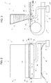
Figure 2 is a frontal and schematic view of a detail of one of the plant machines inFigure 1 ; -
Figure 3 is a lateral and schematic view of the detail inFigure 2 ; -
Figure 4 is a frontal and schematic view of a detail of a prior art machine; -
Figure 5 is a lateral and schematic view of the detail inFigure 4 ; -
Figure 6 is a frontal and schematic view of an alternative detail to the detail inFigure 2 ; and -
Figure 7 is a lateral and schematic view of the detail inFigure 6 . - In
Figure 1 , PL designates, as a whole, a plant for the manufacture of a ceramic article T. In particular, the ceramic article T is a tile or a slab. -
Plant 1 comprises amachine 1 for compacting a powder material CP comprising ceramic powder (e.g. containing clays, sands, and/or feldspars). Themachine 1 comprises a compacting device 2, which is arranged at a working station 3 and is designed to compact the ceramic powder CP so as to obtain a layer of compacted ceramic powder KP; aconveyor assembly 4 to transport the ceramic powder CP (in a substantially continuous manner) along a first portion PA of a given path (in a moving direction A) from aninput station 5 to the working station 3 and the layer of compacted ceramic powder KP along a second portion PB of the given path from the working station 3 (to an output station 6); and afeeding assembly 7, which is designed to feed the ceramic powder CP to theconveyor assembly 4 at theinput station 5. - In particular, the
feeding assembly 7 feeds the ceramic powder to theconveyor assembly 4 in a substantially continuous manner. - In particular, the
conveyor assembly 4 is also designed to support the powder material CP and the compacted powder material KP from below. - The
conveyor assembly 4 comprises aconveyor belt 8. Thefeeding assembly 7 is designed to feed the powder material CP to (on) theconveyor belt 8 at theinput station 5. - In particular, the
conveyor belt 8 has asupport surface 9 and is designed to transport (and to support) the powder material CP along (at least part of) the first portion PA. Thefeeding assembly 7 is designed to feed the powder material to thesupport surface 9. - The
machine 1 comprises astraightening device 10, which comprises at least one suckinghead 11, arranged at theinput station 5 and designed to exert a force (in particular, by means of sucking) on theconveyor belt 8 to increase the flatness of the conveyor belt 8 (at least) at theinput station 5. - It has been experimentally observed that in this way each ceramic article T has, surprisingly, a homogeneous density and/or thickness as well as/or a correct geometry (
Figures 2 and 3 ) . - After having noted the above, it was also noted that (as shown in
Figures 4 and 5 ), if this device is not implemented, thepressure belt 13 tends to deform (in particular, after a certain length of use). In this way (as more clearly shown inFigure 4 ), some areas of the layer of ceramic powder CP (in particular, those closest to the longitudinal edges of the conveyor belt 4) are less thick (and, therefore, have less ceramic powder CP). The thickness of the powder material CP affects the density of the compacted product (the base article 15); this density is, in turn, correlated with the size and geometry of the ceramic article T (after firing). - In particular, in use, a pressure less than atmospheric pressure is created inside the sucking
head 11. The difference in pressure means that theconveyor belt 8 is subjected to a vertical force that, by bending it, makes it flat at thefeeding assembly 7, thus ensuring correct loading of the powder material CP on theconveyor belt 8 itself. - According to some non-limiting embodiments, the
straightening device 10 comprises a sucking unit 10' (in particular, a pump) and at least one conduit to connect the sucking unit 10' to the suckinghead 11. - In some cases, the
straightening device 10 comprises a sensor (known and not shown) to detect the pressure set by the sucking unit 10' and a control system (not shown) for emitting an alarm signal if the pressure detected is incorrect (too high). - Advantageously but not necessarily, the
conveyor belt 8 comprises (at least) one metal material (more precisely, steel). In particular, theconveyor belt 8 is (mainly) made of metal material (more precisely, steel). - In some cases, the feeding assembly 7 (in particular, see
Figure 1 ) is designed to carry a layer of (non-compacted) ceramic powder CP to (onto) the conveyor belt 8 (at the input station 5); the compacting device 2 is designed to exert pressure on the layer of ceramic powder CP transverse (in particular, normal) to thesupport surface 9. - According to some non-limiting embodiments, the compacting device 2 comprises at least one compression roller 12 (in particular, two
compression rollers 12 arranged on opposite bands - one above and one below - of the conveyor belt 8) for exerting pressure on the ceramic powder CP so as to compact the ceramic powder CP itself. - Although in
Figure 1 only tworollers 12 are shown, in accordance with some variants, it is also possible to provide a plurality ofrollers 12 arranged above and below theconveyor belt 8, as described, for example, in patentEP1641607B1 . - In particular, the compacting device 2 also comprises at least one actuator (in particular, a fluid-dynamic one - that is known and not shown) designed to push the
compression roller 12 downwards and towards theconveyor assembly 4. - Advantageously (as in the embodiment shown in
Figure 1 ) but not necessarily, the compacting device 2 comprises apressure belt 13. - In particular, the
pressure belt 13 converges towards theconveyor belt 8 in the moving direction A in which theconveyor assembly 4 feeds the ceramic powder CP to the compacting device 2. In this way, pressure is exerted (from top to bottom) that gradually increases in the direction A on the ceramic powder CP so that it is compacted. - In particular, the
pressure belt 13 is (mainly) made of metal (steel) so that it is not substantially deformed while pressure is exerted on the ceramic powder. - According to specific embodiments (such as that shown in
Figure 1 ), the compacting device also comprises an opposing belt 13' that is arranged on the opposite side of the conveyor belt 8 (in particular, made of rubber or a similar material) with respect to thepressure belt 13 to work together with theconveyor belt 8 to provide an appropriate response to the force exerted downwards by thepressure belt 13. In these cases, in particular, the opposing belt 13' is (mainly) made of metal (steel) so that it is not substantially deformed while pressure is exerted on the ceramic powder. - Advantageously but not necessarily, the opposing belt 13' and the
conveyor belt 8 coincide. In other words, the opposing belt 13' is absent (and, in particular, theconveyor belt 8 is - mainly - made of metal - steel). In these cases, theconveyor belt 8 also performs the functions of the opposing belt 13' (as described above). - Advantageously but not necessarily, the
conveyor belt 8 ends at (the end of) the working station 3. In these cases, theconveyor assembly 4 comprises an additional belt for conveying (not shown), which is arranged immediately downstream of the compacting device 2 and is designed to advance the compacted ceramic powder KP (in the direction A) at a different speed (in particular, faster) than the speed at which theconveyor belt 11 conveys the ceramic powder CP to (and through) the working station 3. More precisely, the speed of the additional belt for conveying (not shown) is adapted to (corresponds to) the speed at which the compacted ceramic powder KP exits the compacting device 2. - As an alternative or in addition to the above, according to some non-limiting embodiments, the
feeding assembly 7 is designed to bring a layer of (non-compacted) ceramic powder CP to (onto) the conveyor assembly 4 (more precisely, onto the conveyor belt 8), which is designed to feed the layer of ceramic powder CP to the compacting device 2 in the moving direction A. - According to some non-limiting embodiments, the plant PL also comprises a
cutting assembly 14 for transversely cutting the layer of compacted ceramic powder KP so as to obtain a base article 15 (more precisely, a plurality ofbase articles 15; even more precisely, base slabs), which (each of which) is a portion of the layer of compacted powder KP. More in particular, thecutting assembly 14 is arranged along the portion PB of the given path (more in particular, downstream of the compacting device 2; even more particularly, between the working station 3 and the output station 6). In particular, thebase articles 15 consist of compacted ceramic powder KP. - Advantageously but not necessarily, the
conveyor assembly 4 is designed to feed the layer of compacted powder KP to the cuttingassembly 14 and to transport thebase article 15 downstream of the cuttingassembly 14. - Advantageously, the cutting
assembly 14 comprises acutting blade 16, which is designed to enter into contact with the layer of compacted ceramic powder KP, in order to cut it, and ahandling unit 17, to move thecutting blade 16 along a path that is diagonal to the direction A. In this way, it is possible to provide thebase articles 15 withend edges 18 that are substantially perpendicular to the direction A while the layer of compacted ceramic powder KP is continuously advanced. - According to some embodiments (such as that shown in
Figures 1 and2 ), the cuttingassembly 14 also comprises twoadditional blades 19, which are arranged on opposite sides of the portion PB and are designed to cut the layer of compacted ceramic powder KP and to define the lateral edges 20 of thebase articles 15 substantially perpendicular to the edges 18 (and substantially parallel to the direction A). In some specific cases, the cuttingassembly 14 is similar to that described in the patent application with publication numberEP1415780 . - According to some non-limiting embodiments, the plant PL also comprises a dryer 21 (
Figure 1 ) arranged along the second portion PB of the given path downstream from the compacting device 2 (more precisely, downstream from the cutting assembly 14). - According to some non-limiting embodiments, the
plant 1 also comprises at least onefiring kiln 22 for sintering (the layer of compacted powder KP of) thebase article 15 so as to obtain the ceramic product T. In particular, the firingkiln 22 is arranged along the second portion PB of the given path downstream of the compacting device 2 (and downstream of the cuttingassembly 14; in particular, also downstream of the dryer 21). - According to some non-limiting embodiments, a
printing unit 23 may be provided to decorate the surface of at least a portion of the layer of compacted powder KP (in particular, of the base article 15). - Typically but not necessarily, the
printing unit 23 is arranged upstream of the firing kiln 22 (and, in particular, downstream of the dryer 21). - In particular, the feeding
assembly 7 has an output mouth 24 (seeFigures 2 and 3 in particular), which faces thesupport surface 9 and through which, in use, the powder material CP passes to reach thesupport surface 9. - According to some non-limiting embodiments, the machine 1 (more particularly, the feeding unit 7) comprises a levelling
device 25, designed to at least partially level the powder material CP on theconveyor belt 8 upstream of the working station 3 (and arranged along the first portion PA). In particular, the levellingdevice 25 is arranged at theinput station 5. Advantageously, but not necessarily, the levellingdevice 25 at least partially delimits theoutput mouth 24 transversely to the moving direction A (downstream of the output mouth 24). More precisely, but not necessarily, the levellingdevice 25 is an edge (transverse - in particular perpendicular - to the direction A) of theoutput mouth 24. - According to specific and non-limiting embodiments, the levelling
device 25 comprises (is) a plate (transverse - particularly perpendicular - to the direction A) e.g. made of metal or a suitable polymer (such as polyurethane). - In particular, the
conveyor belt 8 is arranged between the suckinghead 11 and the feedingassembly 7. - More particularly, the
conveyor belt 8 is arranged between the suckinghead 11 and theoutput mouth 24. - In particular, the
conveyor belt 8 is arranged between the suckinghead 11 and the levellingdevice 25. - Advantageously but not necessarily, the sucking
head 11 extends transversely to the moving direction A. - According to some non-limiting embodiments, the
conveyor belt 8 has anactive portion 26 that extends longitudinally along (at least part of) the first portion PA of the given path. - In some non-limiting cases, the sucking
head 11 extends transversely to the conveyor belt 8 (in particular, to the active portion 26) so as to present afirst end 27 at a firstlongitudinal edge 28 of the conveyor belt 8 (in particular, of the active portion 26) and asecond end 29 at a second longitudinal edge 30 (opposite to the longitudinal edge 28) of the conveyor belt 8 (in particular, of the active portion 26) . - Alternatively (
Figures 6 and 7 ), the suckinghead 11 is arranged at the first longitudinal edge 28 (of the active portion 26). The straighteningdevice 10 comprises an additional sucking head 11' arranged at the second longitudinal edge 30 (of the active portion 26). - Advantageously but not necessarily (
Figures 2, 3 ,6, and 7 ), the straighteningdevice 10 comprises at least onesupport 31, which (is arranged, in particular, on the opposite side of theconveyor belt 8 with respect to the feeding assembly 7 - more particularly, immediately downstream and/or upstream of the suckinghead 11 and) is designed to support theconveyor belt 8 downstream and/or upstream (with respect to the direction A) of the suckinghead 11. - More precisely, but not necessarily, the
support 31 is arranged (is designed to come) in contact with the conveyor belt 8 (in particular, with the surface of theconveyor belt 8 opposite to the support surface 9). - According to some non-limiting embodiments, the straightening
device 10 comprises at least twosupports 31, of which at least one is arranged (immediately) upstream of the suckinghead 11 and at least one is arranged (immediately) downstream of the suckinghead 11. - Advantageously but not necessarily, the sucking
head 11 comprises an end gasket 32 (designed to come) in contact with theconveyor belt 8, in particular designed to come into contact with a further surface of theconveyor belt 8 opposite to thesupport surface 9. More particularly, theconveyor belt 8 is designed to slide on thegasket 32. - The
gasket 32 enables a better seal, between theconveyor belt 8 and the suckinghead 11, to be obtained. - In particular, the (framed)
gasket 32 extends along the whole external profile of the sucking head 11 (more precisely, of the whole sucking opening of the sucking head 11) . - Advantageously but not necessarily, the
gasket 32 comprises a (is made of, in particular) rubber. According to some non-limiting embodiments, thegasket 32 comprises (is - mainly - made of, in particular) polyethylene terephthalate. According to some specifications and non-limiting embodiments, thegasket 32 comprises (is - mainly - made of, in particular) Ertalyte® PET-P. - A method for compacting a powder material CP comprising ceramic powder (e.g. powder containing clays, sands, and/or feldspars) is also provided.
- The method comprises at least one compacting step, during which the powder material CP is compacted, at a working station 3, so as to obtain a layer of compacted powder material KP; a conveying step, during which the powder material CP is conveyed by means of a
conveyor assembly 4 along a first portion PA of a given path from aninput station 5 to the working station 3 and the layer of compacted powder material KP is conveyed from the working station 3 along a second portion PB of the given path; and a feeding step, during which the powder material CP is fed to (onto) aconveyor belt 8 of theconveyor assembly 4 at theinput station 6 by means of a feedingassembly 7. - In particular, the conveying step and the feeding step are at least partially simultaneous.
- The method also comprises a straightening step, during which a
straightening device 10 is designed to exert a force by means of sucking on theconveyor belt 8 to increase the flatness of theconveyor belt 8 itself at least at theinput station 5. The feeding step and the straightening step being at least partially simultaneous. - Advantageously but not necessarily, the method is implemented by a
machine 1 as described above. - According to some non-limiting embodiments, the method comprises a levelling step, during which the powder material CP arranged on the
conveyor belt 8 upstream of the working station 3 (in particular, at the input station 5) is at least partially levelled. In particular, the feeding step and the levelling step are at least partially simultaneous. - A procedure for the production of ceramic articles T is also provided. The procedure comprises a method for compacting a powder material CP in accordance with that described above. The procedure comprises a firing step, during which (at least) a portion of the layer of compacted powder material (KP) is fired.
- In particular, the procedure is implemented by the plant PL.
- Unless expressly indicated to the contrary, the contents of the references (articles, books, and patent applications etc.) cited in this text are herein recalled in full. In particular, the above-mentioned references are herein incorporated by reference.
Claims (15)
- A machine for compacting a powder material (CP) comprising ceramic powder; the machine (1) comprises a compacting device (2), which is arranged at a working station (3) and is designed to compact the powder material (CP) so as to obtain a layer of compacted powder material (KP); a conveyor assembly (4) to transport the powder material (CP) along a first portion (PA) of a given path from an input station (5) to the working station (3) and the layer of compacted powder material (KP) from the working station (3) along a second portion (OB) of the given path; and a feeding assembly (7), which is designed to feed the powder material (CP) to the conveyor assembly (4) at the input station (5);
the conveyor assembly (4) comprises a conveyor belt (8); the feeding assembly (7) is designed to feed the powder material (CP) to the conveyor belt (8) at the input station (5) ;
the machine (1) being characterized in that it comprises a straightening device (10), which comprises at least one sucking head (11) arranged in the area of the input station (5) and designed to exert a force aimed at increasing the flatness of the conveyor belt (8) at least at the input station (5). - The machine according to claim 1, wherein the conveyor belt (8) comprises a metal material; in particular, the conveyor belt (8) is mainly made of a metal material.
- The machine according to claim 1 or 2 and comprising a levelling device (25) arranged along the first portion (PA) and designed to at least partially level the powder material (CP) on the conveyor belt (8) upstream of the working station (3).
- The machine according to any one of the preceding claims, wherein the conveyor belt (4) has a support surface, onto which the feeding assembly (7) is designed to feed the powder material (CP); the feeding assembly (7) has an output mouth (24), which faces the support surface (9) and through which, in use, the powder material (CP) passes in order to reach the support surface (9).
- The machine according to claim 4, wherein the conveyor assembly (4) is designed to transport the powder material (CP) along the first portion (PA) in a moving direction (A); the machine (1) comprises a levelling device (25), which is designed to level the powder material (CP) on the conveyor belt (8) upstream of the working station (3) and at least partially delimits the output mouth (24) transversely to the moving direction (A).
- The machine according to any one of the preceding claims, wherein the conveyor belt (8) is arranged between the sucking head (11) and the feeding assembly (7); in particular, the conveyor belt (8) is arranged between the sucking head (11) and the output mouth (24).
- The machine according to any one of the preceding claims, wherein the conveyor belt (8) has an active portion (26), which extends longitudinally along at least part of the first portion (PA) of the given path; said sucking head (11) extends transversely to the active portion (26) so as to have a first end (27) in the area of a first longitudinal edge (28) of the active portion (26) and a second end (29) in the area of a second longitudinal edge (30), opposite the first longitudinal edge (28) of the active portion (26).
- The machine according to any one of the preceding claims, wherein the conveyor belt (8) has an active portion (26), which extends longitudinally along at least part of the first portion (PA) of the given path; said sucking head (11) being arranged in the area of a first longitudinal edge (28) of the active portion (26); the straightening device (10) comprising a further sucking head (11') arranged in the area of a second longitudinal edge (30) of the active portion (26) .
- The machine according to any one of the preceding claims, wherein the conveyor assembly (4) is designed to transport the powder material (CP) along the first portion (PA) in a moving direction (A); the straightening device (10) comprising at least one support (31), which is designed to support the conveyor belt downstream and/or upstream of the sucking head (11).
- The machine according to any one of the preceding claims, wherein the sucking head comprises an end gasket (32) in contact with the conveyor belt (8), in particular in contact with a further surface of the conveyor belt (8) opposite said support surface (9).
- A plant for the production of ceramic articles; the plant comprises at least one machine (1) for compacting ceramic powder according to any one of the preceding claims and provided with a cutting assembly (14) to transversely cut the layer of compacted ceramic powder (KP) so as to obtain base articles (15), each having a portion of the layer of compacted ceramic powder (KP); and at least one firing kiln (22) to sinter the compacted ceramic powder (KP) of the base articles (15) so as to obtain the ceramic articles (T).
- A method for compacting a powder material (CP) comprising ceramic powder; the method comprises at least one compacting step, during which the powder material (CP) is compacted at a working station (3) so as to obtain a layer of compacted powder material (KP); a conveying step, during which the powder material (CP) is conveyed, by means of a conveyor assembly (4), along a first portion (PA) of a given path from an input station (5) to the working station (3) and the layer of compacted powder material (KP) is conveyed from the working station (3) along a second portion (PB) of the given path; and a feeding step, during which the powder material (CP) is fed to a conveyor belt (8) of the conveyor assembly (4) at the input station (6) by means of a feeding assembly (7); in particular, the conveying step and the feeding step are at least partially simultaneous;
the method being characterized in that it comprises a straightening step, during which a straightening device (10) is designed to exert a force, through sucking, upon the conveyor belt (8) in order to increase the flatness of the conveyor belt (8) at least at the input station (5); the feeding step and the straightening step being at least partially simultaneous. - The method according to claim 12 and implemented by a machine (1) according to any one of the claims from 1 to 10.
- The method according to claim 12 or 13 and comprising a levelling step, during which the powder material (CP) arranged in the conveyor belt (8) upstream of the working station (3) is at least partially levelled; in particular, the feeding step and the levelling step being at least partially simultaneous.
- A process for the production of ceramic articles (T); the process comprises a method for compacting a powder material (CP) according to any one of the claims from 12 to 14; and a firing step, during which at least a portion of the layer of compacted powder material (KP) is fired.
Applications Claiming Priority (1)
| Application Number | Priority Date | Filing Date | Title |
|---|---|---|---|
| IT201800008650 | 2018-09-17 |
Publications (2)
| Publication Number | Publication Date |
|---|---|
| EP3623130A1 true EP3623130A1 (en) | 2020-03-18 |
| EP3623130B1 EP3623130B1 (en) | 2024-08-21 |
Family
ID=64557005
Family Applications (1)
| Application Number | Title | Priority Date | Filing Date |
|---|---|---|---|
| EP19197157.1A Active EP3623130B1 (en) | 2018-09-17 | 2019-09-13 | Machine and method for compacting a powder material |
Country Status (7)
| Country | Link |
|---|---|
| US (1) | US20200086525A1 (en) |
| EP (1) | EP3623130B1 (en) |
| CN (1) | CN110900791B (en) |
| BR (1) | BR102019019194A2 (en) |
| ES (1) | ES2989796T3 (en) |
| MX (1) | MX2019010976A (en) |
| RU (1) | RU2019128285A (en) |
Citations (6)
| Publication number | Priority date | Publication date | Assignee | Title |
|---|---|---|---|---|
| US4290988A (en) * | 1978-10-17 | 1981-09-22 | Casimir Kast Gmbh & Co. Kg | Method for the manufacture of cellulosic fibrous material which can be pressed into moulded parts |
| JPH11226925A (en) * | 1998-02-12 | 1999-08-24 | Sekisui Chem Co Ltd | Hydraulic inorganic molded article and method for producing the same |
| JP2001018207A (en) * | 1999-07-08 | 2001-01-23 | Asahi Giken Kogyo Kk | Manufacture of wooden powder board |
| EP1415780A2 (en) | 2002-11-04 | 2004-05-06 | SACMI COOPERATIVA MECCANICI IMOLA Soc. Coop. a r.l. | Apparatus for cutting a continuous flat ceramic web into slabs |
| WO2005068146A2 (en) * | 2004-01-08 | 2005-07-28 | Sacmi Cooperativa Meccanici Imola Societa' Cooperativa | Method and plant for prearranging powders for forming ceramic tiles or slabs |
| EP1641607A1 (en) | 2003-07-07 | 2006-04-05 | Sacmi Cooperativa Meccanici Imola Societa' Cooperativa | Method and plant for forming ceramic slabs or tiles of controlled thickness |
Family Cites Families (4)
| Publication number | Priority date | Publication date | Assignee | Title |
|---|---|---|---|---|
| ITRE20030004A1 (en) * | 2003-01-20 | 2004-07-21 | Sacmi | METHOD AND PLANT FOR THE FORMING OF SLABS OR CERAMIC TILES. |
| ITRE20040153A1 (en) * | 2004-12-22 | 2005-03-22 | Sacmi | DEVICE FOR PRODUCING CERAMIC SHEETS |
| ITUA20164307A1 (en) * | 2016-06-13 | 2017-12-13 | Sacmi | MACHINE AND METHOD FOR THE COMPACTION OF CERAMIC POWDER |
| IT201600093579A1 (en) * | 2016-09-16 | 2018-03-16 | Sacmi | METHOD AND APPARATUS FOR FORMING COMPACT POWDER DUTIES |
-
2019
- 2019-09-09 RU RU2019128285A patent/RU2019128285A/en unknown
- 2019-09-13 EP EP19197157.1A patent/EP3623130B1/en active Active
- 2019-09-13 ES ES19197157T patent/ES2989796T3/en active Active
- 2019-09-13 MX MX2019010976A patent/MX2019010976A/en unknown
- 2019-09-16 BR BR102019019194-5A patent/BR102019019194A2/en not_active Application Discontinuation
- 2019-09-16 CN CN201910871101.9A patent/CN110900791B/en active Active
- 2019-09-17 US US16/572,832 patent/US20200086525A1/en not_active Abandoned
Patent Citations (6)
| Publication number | Priority date | Publication date | Assignee | Title |
|---|---|---|---|---|
| US4290988A (en) * | 1978-10-17 | 1981-09-22 | Casimir Kast Gmbh & Co. Kg | Method for the manufacture of cellulosic fibrous material which can be pressed into moulded parts |
| JPH11226925A (en) * | 1998-02-12 | 1999-08-24 | Sekisui Chem Co Ltd | Hydraulic inorganic molded article and method for producing the same |
| JP2001018207A (en) * | 1999-07-08 | 2001-01-23 | Asahi Giken Kogyo Kk | Manufacture of wooden powder board |
| EP1415780A2 (en) | 2002-11-04 | 2004-05-06 | SACMI COOPERATIVA MECCANICI IMOLA Soc. Coop. a r.l. | Apparatus for cutting a continuous flat ceramic web into slabs |
| EP1641607A1 (en) | 2003-07-07 | 2006-04-05 | Sacmi Cooperativa Meccanici Imola Societa' Cooperativa | Method and plant for forming ceramic slabs or tiles of controlled thickness |
| WO2005068146A2 (en) * | 2004-01-08 | 2005-07-28 | Sacmi Cooperativa Meccanici Imola Societa' Cooperativa | Method and plant for prearranging powders for forming ceramic tiles or slabs |
Also Published As
| Publication number | Publication date |
|---|---|
| US20200086525A1 (en) | 2020-03-19 |
| CN110900791B (en) | 2024-09-27 |
| RU2019128285A (en) | 2021-03-09 |
| MX2019010976A (en) | 2022-05-06 |
| ES2989796T3 (en) | 2024-11-27 |
| BR102019019194A2 (en) | 2020-05-26 |
| CN110900791A (en) | 2020-03-24 |
| EP3623130B1 (en) | 2024-08-21 |
Similar Documents
| Publication | Publication Date | Title |
|---|---|---|
| RU2705685C1 (en) | Apparatus and method for pressing ceramic powder | |
| JP5483831B2 (en) | Method for printing on flat materials | |
| EP3509833B1 (en) | Device for compacting powder material, in particular ceramic material | |
| EP3852991B1 (en) | Machine and method for compacting powder material | |
| WO2019171166A1 (en) | Machine and method for compacting a powder material | |
| EP2763827B1 (en) | Device and method for processing a layer of powder material | |
| EP4334098B1 (en) | Manufacturing system and method for manufacturing articles made of compacted ceramic powder | |
| US6659266B2 (en) | Apparatus and method for feeding elongated elements | |
| KR101962551B1 (en) | Tension control device and conveying device | |
| KR20150061601A (en) | Cutting device of glass sheet, cutting method of glass sheet and producing method of glass sheet | |
| EP3623130B1 (en) | Machine and method for compacting a powder material | |
| US20080173519A1 (en) | Centralizing conveyer assembly and method of centralizing a conveyed product | |
| KR101403474B1 (en) | Trimming device of a strip | |
| EP4427897A1 (en) | Manufacturing method and system for manufacturing ceramic articles | |
| EP2546040B1 (en) | Compact line for cutting and profiling of strips or listels. | |
| JP4703914B2 (en) | Sheet alignment device | |
| KR101867679B1 (en) | Strip center position controller | |
| CN114851403B (en) | Belt type upper and lower cutter numerical control cutting machine | |
| EP2429789B1 (en) | Device and method for rounding off the longitudinal edges of heavy clay products during the production phase particularly, but not exclusively, for extruded bent tiles | |
| WO2025181713A1 (en) | Compaction method and system for compacting ceramic powder material | |
| JPWO2023079991A5 (en) | ||
| JP2008143640A (en) | Paper feeding hopper | |
| BR112021005298B1 (en) | MACHINE, PLANT FOR THE PRODUCTION OF CERAMIC ARTICLES AND METHOD FOR COMPACTING POWDERED MATERIAL | |
| WO2026062594A1 (en) | System for the manufacturing of ceramic items and related method | |
| CN117157177A (en) | Method and system for manufacturing ceramic articles |
Legal Events
| Date | Code | Title | Description |
|---|---|---|---|
| PUAI | Public reference made under article 153(3) epc to a published international application that has entered the european phase |
Free format text: ORIGINAL CODE: 0009012 |
|
| STAA | Information on the status of an ep patent application or granted ep patent |
Free format text: STATUS: THE APPLICATION HAS BEEN PUBLISHED |
|
| AK | Designated contracting states |
Kind code of ref document: A1 Designated state(s): AL AT BE BG CH CY CZ DE DK EE ES FI FR GB GR HR HU IE IS IT LI LT LU LV MC MK MT NL NO PL PT RO RS SE SI SK SM TR |
|
| AX | Request for extension of the european patent |
Extension state: BA ME |
|
| STAA | Information on the status of an ep patent application or granted ep patent |
Free format text: STATUS: REQUEST FOR EXAMINATION WAS MADE |
|
| 17P | Request for examination filed |
Effective date: 20200916 |
|
| RBV | Designated contracting states (corrected) |
Designated state(s): AL AT BE BG CH CY CZ DE DK EE ES FI FR GB GR HR HU IE IS IT LI LT LU LV MC MK MT NL NO PL PT RO RS SE SI SK SM TR |
|
| STAA | Information on the status of an ep patent application or granted ep patent |
Free format text: STATUS: EXAMINATION IS IN PROGRESS |
|
| 17Q | First examination report despatched |
Effective date: 20220706 |
|
| P01 | Opt-out of the competence of the unified patent court (upc) registered |
Effective date: 20230516 |
|
| GRAP | Despatch of communication of intention to grant a patent |
Free format text: ORIGINAL CODE: EPIDOSNIGR1 |
|
| STAA | Information on the status of an ep patent application or granted ep patent |
Free format text: STATUS: GRANT OF PATENT IS INTENDED |
|
| INTG | Intention to grant announced |
Effective date: 20231206 |
|
| GRAJ | Information related to disapproval of communication of intention to grant by the applicant or resumption of examination proceedings by the epo deleted |
Free format text: ORIGINAL CODE: EPIDOSDIGR1 |
|
| STAA | Information on the status of an ep patent application or granted ep patent |
Free format text: STATUS: EXAMINATION IS IN PROGRESS |
|
| INTC | Intention to grant announced (deleted) | ||
| RIN1 | Information on inventor provided before grant (corrected) |
Inventor name: BERTOZZI, MAURO Inventor name: BABINI, ALAN Inventor name: SALIERI, MARCO |
|
| GRAP | Despatch of communication of intention to grant a patent |
Free format text: ORIGINAL CODE: EPIDOSNIGR1 |
|
| STAA | Information on the status of an ep patent application or granted ep patent |
Free format text: STATUS: GRANT OF PATENT IS INTENDED |
|
| INTG | Intention to grant announced |
Effective date: 20240409 |
|
| GRAS | Grant fee paid |
Free format text: ORIGINAL CODE: EPIDOSNIGR3 |
|
| GRAA | (expected) grant |
Free format text: ORIGINAL CODE: 0009210 |
|
| STAA | Information on the status of an ep patent application or granted ep patent |
Free format text: STATUS: THE PATENT HAS BEEN GRANTED |
|
| AK | Designated contracting states |
Kind code of ref document: B1 Designated state(s): AL AT BE BG CH CY CZ DE DK EE ES FI FR GB GR HR HU IE IS IT LI LT LU LV MC MK MT NL NO PL PT RO RS SE SI SK SM TR |
|
| REG | Reference to a national code |
Ref country code: GB Ref legal event code: FG4D |
|
| REG | Reference to a national code |
Ref country code: CH Ref legal event code: EP |
|
| REG | Reference to a national code |
Ref country code: DE Ref legal event code: R096 Ref document number: 602019057294 Country of ref document: DE |
|
| REG | Reference to a national code |
Ref country code: IE Ref legal event code: FG4D |
|
| REG | Reference to a national code |
Ref country code: ES Ref legal event code: FG2A Ref document number: 2989796 Country of ref document: ES Kind code of ref document: T3 Effective date: 20241127 |
|
| REG | Reference to a national code |
Ref country code: LT Ref legal event code: MG9D |
|
| REG | Reference to a national code |
Ref country code: NL Ref legal event code: MP Effective date: 20240821 |
|
| PG25 | Lapsed in a contracting state [announced via postgrant information from national office to epo] |
Ref country code: NO Free format text: LAPSE BECAUSE OF FAILURE TO SUBMIT A TRANSLATION OF THE DESCRIPTION OR TO PAY THE FEE WITHIN THE PRESCRIBED TIME-LIMIT Effective date: 20241121 |
|
| REG | Reference to a national code |
Ref country code: AT Ref legal event code: MK05 Ref document number: 1715113 Country of ref document: AT Kind code of ref document: T Effective date: 20240821 |
|
| PG25 | Lapsed in a contracting state [announced via postgrant information from national office to epo] |
Ref country code: NL Free format text: LAPSE BECAUSE OF FAILURE TO SUBMIT A TRANSLATION OF THE DESCRIPTION OR TO PAY THE FEE WITHIN THE PRESCRIBED TIME-LIMIT Effective date: 20240821 Ref country code: FI Free format text: LAPSE BECAUSE OF FAILURE TO SUBMIT A TRANSLATION OF THE DESCRIPTION OR TO PAY THE FEE WITHIN THE PRESCRIBED TIME-LIMIT Effective date: 20240821 Ref country code: PL Free format text: LAPSE BECAUSE OF FAILURE TO SUBMIT A TRANSLATION OF THE DESCRIPTION OR TO PAY THE FEE WITHIN THE PRESCRIBED TIME-LIMIT Effective date: 20240821 Ref country code: GR Free format text: LAPSE BECAUSE OF FAILURE TO SUBMIT A TRANSLATION OF THE DESCRIPTION OR TO PAY THE FEE WITHIN THE PRESCRIBED TIME-LIMIT Effective date: 20241122 Ref country code: PT Free format text: LAPSE BECAUSE OF FAILURE TO SUBMIT A TRANSLATION OF THE DESCRIPTION OR TO PAY THE FEE WITHIN THE PRESCRIBED TIME-LIMIT Effective date: 20241223 |
|
| PG25 | Lapsed in a contracting state [announced via postgrant information from national office to epo] |
Ref country code: BG Free format text: LAPSE BECAUSE OF FAILURE TO SUBMIT A TRANSLATION OF THE DESCRIPTION OR TO PAY THE FEE WITHIN THE PRESCRIBED TIME-LIMIT Effective date: 20240821 |
|
| PG25 | Lapsed in a contracting state [announced via postgrant information from national office to epo] |
Ref country code: LV Free format text: LAPSE BECAUSE OF FAILURE TO SUBMIT A TRANSLATION OF THE DESCRIPTION OR TO PAY THE FEE WITHIN THE PRESCRIBED TIME-LIMIT Effective date: 20240821 |
|
| PG25 | Lapsed in a contracting state [announced via postgrant information from national office to epo] |
Ref country code: IS Free format text: LAPSE BECAUSE OF FAILURE TO SUBMIT A TRANSLATION OF THE DESCRIPTION OR TO PAY THE FEE WITHIN THE PRESCRIBED TIME-LIMIT Effective date: 20241221 Ref country code: AT Free format text: LAPSE BECAUSE OF FAILURE TO SUBMIT A TRANSLATION OF THE DESCRIPTION OR TO PAY THE FEE WITHIN THE PRESCRIBED TIME-LIMIT Effective date: 20240821 |
|
| PG25 | Lapsed in a contracting state [announced via postgrant information from national office to epo] |
Ref country code: HR Free format text: LAPSE BECAUSE OF FAILURE TO SUBMIT A TRANSLATION OF THE DESCRIPTION OR TO PAY THE FEE WITHIN THE PRESCRIBED TIME-LIMIT Effective date: 20240821 |
|
| PG25 | Lapsed in a contracting state [announced via postgrant information from national office to epo] |
Ref country code: RS Free format text: LAPSE BECAUSE OF FAILURE TO SUBMIT A TRANSLATION OF THE DESCRIPTION OR TO PAY THE FEE WITHIN THE PRESCRIBED TIME-LIMIT Effective date: 20241121 |
|
| PG25 | Lapsed in a contracting state [announced via postgrant information from national office to epo] |
Ref country code: RS Free format text: LAPSE BECAUSE OF FAILURE TO SUBMIT A TRANSLATION OF THE DESCRIPTION OR TO PAY THE FEE WITHIN THE PRESCRIBED TIME-LIMIT Effective date: 20241121 Ref country code: PT Free format text: LAPSE BECAUSE OF FAILURE TO SUBMIT A TRANSLATION OF THE DESCRIPTION OR TO PAY THE FEE WITHIN THE PRESCRIBED TIME-LIMIT Effective date: 20241223 Ref country code: PL Free format text: LAPSE BECAUSE OF FAILURE TO SUBMIT A TRANSLATION OF THE DESCRIPTION OR TO PAY THE FEE WITHIN THE PRESCRIBED TIME-LIMIT Effective date: 20240821 Ref country code: NO Free format text: LAPSE BECAUSE OF FAILURE TO SUBMIT A TRANSLATION OF THE DESCRIPTION OR TO PAY THE FEE WITHIN THE PRESCRIBED TIME-LIMIT Effective date: 20241121 Ref country code: NL Free format text: LAPSE BECAUSE OF FAILURE TO SUBMIT A TRANSLATION OF THE DESCRIPTION OR TO PAY THE FEE WITHIN THE PRESCRIBED TIME-LIMIT Effective date: 20240821 Ref country code: LV Free format text: LAPSE BECAUSE OF FAILURE TO SUBMIT A TRANSLATION OF THE DESCRIPTION OR TO PAY THE FEE WITHIN THE PRESCRIBED TIME-LIMIT Effective date: 20240821 Ref country code: IS Free format text: LAPSE BECAUSE OF FAILURE TO SUBMIT A TRANSLATION OF THE DESCRIPTION OR TO PAY THE FEE WITHIN THE PRESCRIBED TIME-LIMIT Effective date: 20241221 Ref country code: HR Free format text: LAPSE BECAUSE OF FAILURE TO SUBMIT A TRANSLATION OF THE DESCRIPTION OR TO PAY THE FEE WITHIN THE PRESCRIBED TIME-LIMIT Effective date: 20240821 Ref country code: GR Free format text: LAPSE BECAUSE OF FAILURE TO SUBMIT A TRANSLATION OF THE DESCRIPTION OR TO PAY THE FEE WITHIN THE PRESCRIBED TIME-LIMIT Effective date: 20241122 Ref country code: FI Free format text: LAPSE BECAUSE OF FAILURE TO SUBMIT A TRANSLATION OF THE DESCRIPTION OR TO PAY THE FEE WITHIN THE PRESCRIBED TIME-LIMIT Effective date: 20240821 Ref country code: BG Free format text: LAPSE BECAUSE OF FAILURE TO SUBMIT A TRANSLATION OF THE DESCRIPTION OR TO PAY THE FEE WITHIN THE PRESCRIBED TIME-LIMIT Effective date: 20240821 Ref country code: AT Free format text: LAPSE BECAUSE OF FAILURE TO SUBMIT A TRANSLATION OF THE DESCRIPTION OR TO PAY THE FEE WITHIN THE PRESCRIBED TIME-LIMIT Effective date: 20240821 |
|
| REG | Reference to a national code |
Ref country code: DE Ref legal event code: R119 Ref document number: 602019057294 Country of ref document: DE |
|
| PG25 | Lapsed in a contracting state [announced via postgrant information from national office to epo] |
Ref country code: SM Free format text: LAPSE BECAUSE OF FAILURE TO SUBMIT A TRANSLATION OF THE DESCRIPTION OR TO PAY THE FEE WITHIN THE PRESCRIBED TIME-LIMIT Effective date: 20240821 Ref country code: DK Free format text: LAPSE BECAUSE OF FAILURE TO SUBMIT A TRANSLATION OF THE DESCRIPTION OR TO PAY THE FEE WITHIN THE PRESCRIBED TIME-LIMIT Effective date: 20240821 Ref country code: RO Free format text: LAPSE BECAUSE OF FAILURE TO SUBMIT A TRANSLATION OF THE DESCRIPTION OR TO PAY THE FEE WITHIN THE PRESCRIBED TIME-LIMIT Effective date: 20240821 |
|
| PG25 | Lapsed in a contracting state [announced via postgrant information from national office to epo] |
Ref country code: EE Free format text: LAPSE BECAUSE OF FAILURE TO SUBMIT A TRANSLATION OF THE DESCRIPTION OR TO PAY THE FEE WITHIN THE PRESCRIBED TIME-LIMIT Effective date: 20240821 |
|
| PG25 | Lapsed in a contracting state [announced via postgrant information from national office to epo] |
Ref country code: CZ Free format text: LAPSE BECAUSE OF FAILURE TO SUBMIT A TRANSLATION OF THE DESCRIPTION OR TO PAY THE FEE WITHIN THE PRESCRIBED TIME-LIMIT Effective date: 20240821 |
|
| PG25 | Lapsed in a contracting state [announced via postgrant information from national office to epo] |
Ref country code: SK Free format text: LAPSE BECAUSE OF FAILURE TO SUBMIT A TRANSLATION OF THE DESCRIPTION OR TO PAY THE FEE WITHIN THE PRESCRIBED TIME-LIMIT Effective date: 20240821 |
|
| REG | Reference to a national code |
Ref country code: CH Ref legal event code: PL |
|
| PG25 | Lapsed in a contracting state [announced via postgrant information from national office to epo] |
Ref country code: LU Free format text: LAPSE BECAUSE OF NON-PAYMENT OF DUE FEES Effective date: 20240913 |
|
| PLBE | No opposition filed within time limit |
Free format text: ORIGINAL CODE: 0009261 |
|
| STAA | Information on the status of an ep patent application or granted ep patent |
Free format text: STATUS: NO OPPOSITION FILED WITHIN TIME LIMIT |
|
| PG25 | Lapsed in a contracting state [announced via postgrant information from national office to epo] |
Ref country code: MC Free format text: LAPSE BECAUSE OF FAILURE TO SUBMIT A TRANSLATION OF THE DESCRIPTION OR TO PAY THE FEE WITHIN THE PRESCRIBED TIME-LIMIT Effective date: 20240821 |
|
| PG25 | Lapsed in a contracting state [announced via postgrant information from national office to epo] |
Ref country code: DE Free format text: LAPSE BECAUSE OF NON-PAYMENT OF DUE FEES Effective date: 20250401 |
|
| REG | Reference to a national code |
Ref country code: BE Ref legal event code: MM Effective date: 20240930 |
|
| PG25 | Lapsed in a contracting state [announced via postgrant information from national office to epo] |
Ref country code: BE Free format text: LAPSE BECAUSE OF NON-PAYMENT OF DUE FEES Effective date: 20240930 Ref country code: IT Free format text: LAPSE BECAUSE OF NON-PAYMENT OF DUE FEES Effective date: 20240913 |
|
| PG25 | Lapsed in a contracting state [announced via postgrant information from national office to epo] |
Ref country code: FR Free format text: LAPSE BECAUSE OF NON-PAYMENT OF DUE FEES Effective date: 20241021 |
|
| GBPC | Gb: european patent ceased through non-payment of renewal fee |
Effective date: 20241121 |
|
| PG25 | Lapsed in a contracting state [announced via postgrant information from national office to epo] |
Ref country code: CH Free format text: LAPSE BECAUSE OF NON-PAYMENT OF DUE FEES Effective date: 20240930 |
|
| PG25 | Lapsed in a contracting state [announced via postgrant information from national office to epo] |
Ref country code: IE Free format text: LAPSE BECAUSE OF NON-PAYMENT OF DUE FEES Effective date: 20240913 |
|
| 26N | No opposition filed |
Effective date: 20250522 |
|
| PG25 | Lapsed in a contracting state [announced via postgrant information from national office to epo] |
Ref country code: SE Free format text: LAPSE BECAUSE OF FAILURE TO SUBMIT A TRANSLATION OF THE DESCRIPTION OR TO PAY THE FEE WITHIN THE PRESCRIBED TIME-LIMIT Effective date: 20240821 |
|
| PG25 | Lapsed in a contracting state [announced via postgrant information from national office to epo] |
Ref country code: GB Free format text: LAPSE BECAUSE OF NON-PAYMENT OF DUE FEES Effective date: 20241121 |
|
| PG25 | Lapsed in a contracting state [announced via postgrant information from national office to epo] |
Ref country code: CY Free format text: LAPSE BECAUSE OF FAILURE TO SUBMIT A TRANSLATION OF THE DESCRIPTION OR TO PAY THE FEE WITHIN THE PRESCRIBED TIME-LIMIT; INVALID AB INITIO Effective date: 20190913 |
|
| PGFP | Annual fee paid to national office [announced via postgrant information from national office to epo] |
Ref country code: ES Payment date: 20251001 Year of fee payment: 7 |
|
| PG25 | Lapsed in a contracting state [announced via postgrant information from national office to epo] |
Ref country code: HU Free format text: LAPSE BECAUSE OF FAILURE TO SUBMIT A TRANSLATION OF THE DESCRIPTION OR TO PAY THE FEE WITHIN THE PRESCRIBED TIME-LIMIT; INVALID AB INITIO Effective date: 20190913 |