EP3623099A1 - Laser metal deposition methodology on graphite substrates for aerospace components - Google Patents
Laser metal deposition methodology on graphite substrates for aerospace components Download PDFInfo
- Publication number
- EP3623099A1 EP3623099A1 EP19196766.0A EP19196766A EP3623099A1 EP 3623099 A1 EP3623099 A1 EP 3623099A1 EP 19196766 A EP19196766 A EP 19196766A EP 3623099 A1 EP3623099 A1 EP 3623099A1
- Authority
- EP
- European Patent Office
- Prior art keywords
- outer sheath
- graphite substrate
- laser
- metal deposition
- graphite
- Prior art date
- Legal status (The legal status is an assumption and is not a legal conclusion. Google has not performed a legal analysis and makes no representation as to the accuracy of the status listed.)
- Granted
Links
Images


Classifications
-
- C—CHEMISTRY; METALLURGY
- C23—COATING METALLIC MATERIAL; COATING MATERIAL WITH METALLIC MATERIAL; CHEMICAL SURFACE TREATMENT; DIFFUSION TREATMENT OF METALLIC MATERIAL; COATING BY VACUUM EVAPORATION, BY SPUTTERING, BY ION IMPLANTATION OR BY CHEMICAL VAPOUR DEPOSITION, IN GENERAL; INHIBITING CORROSION OF METALLIC MATERIAL OR INCRUSTATION IN GENERAL
- C23C—COATING METALLIC MATERIAL; COATING MATERIAL WITH METALLIC MATERIAL; SURFACE TREATMENT OF METALLIC MATERIAL BY DIFFUSION INTO THE SURFACE, BY CHEMICAL CONVERSION OR SUBSTITUTION; COATING BY VACUUM EVAPORATION, BY SPUTTERING, BY ION IMPLANTATION OR BY CHEMICAL VAPOUR DEPOSITION, IN GENERAL
- C23C2/00—Hot-dipping or immersion processes for applying the coating material in the molten state without affecting the shape; Apparatus therefor
- C23C2/04—Hot-dipping or immersion processes for applying the coating material in the molten state without affecting the shape; Apparatus therefor characterised by the coating material
-
- B—PERFORMING OPERATIONS; TRANSPORTING
- B23—MACHINE TOOLS; METAL-WORKING NOT OTHERWISE PROVIDED FOR
- B23P—METAL-WORKING NOT OTHERWISE PROVIDED FOR; COMBINED OPERATIONS; UNIVERSAL MACHINE TOOLS
- B23P15/00—Making specific metal objects by operations not covered by a single other subclass or a group in this subclass
-
- B—PERFORMING OPERATIONS; TRANSPORTING
- B23—MACHINE TOOLS; METAL-WORKING NOT OTHERWISE PROVIDED FOR
- B23K—SOLDERING OR UNSOLDERING; WELDING; CLADDING OR PLATING BY SOLDERING OR WELDING; CUTTING BY APPLYING HEAT LOCALLY, e.g. FLAME CUTTING; WORKING BY LASER BEAM
- B23K26/00—Working by laser beam, e.g. welding, cutting or boring
- B23K26/0006—Working by laser beam, e.g. welding, cutting or boring taking account of the properties of the material involved
-
- B—PERFORMING OPERATIONS; TRANSPORTING
- B23—MACHINE TOOLS; METAL-WORKING NOT OTHERWISE PROVIDED FOR
- B23K—SOLDERING OR UNSOLDERING; WELDING; CLADDING OR PLATING BY SOLDERING OR WELDING; CUTTING BY APPLYING HEAT LOCALLY, e.g. FLAME CUTTING; WORKING BY LASER BEAM
- B23K26/00—Working by laser beam, e.g. welding, cutting or boring
- B23K26/08—Devices involving relative movement between laser beam and workpiece
-
- B—PERFORMING OPERATIONS; TRANSPORTING
- B23—MACHINE TOOLS; METAL-WORKING NOT OTHERWISE PROVIDED FOR
- B23K—SOLDERING OR UNSOLDERING; WELDING; CLADDING OR PLATING BY SOLDERING OR WELDING; CUTTING BY APPLYING HEAT LOCALLY, e.g. FLAME CUTTING; WORKING BY LASER BEAM
- B23K26/00—Working by laser beam, e.g. welding, cutting or boring
- B23K26/12—Working by laser beam, e.g. welding, cutting or boring in a special environment or atmosphere, e.g. in an enclosure
- B23K26/1224—Working by laser beam, e.g. welding, cutting or boring in a special environment or atmosphere, e.g. in an enclosure in vacuum
-
- B—PERFORMING OPERATIONS; TRANSPORTING
- B23—MACHINE TOOLS; METAL-WORKING NOT OTHERWISE PROVIDED FOR
- B23K—SOLDERING OR UNSOLDERING; WELDING; CLADDING OR PLATING BY SOLDERING OR WELDING; CUTTING BY APPLYING HEAT LOCALLY, e.g. FLAME CUTTING; WORKING BY LASER BEAM
- B23K26/00—Working by laser beam, e.g. welding, cutting or boring
- B23K26/12—Working by laser beam, e.g. welding, cutting or boring in a special environment or atmosphere, e.g. in an enclosure
- B23K26/127—Working by laser beam, e.g. welding, cutting or boring in a special environment or atmosphere, e.g. in an enclosure in an enclosure
-
- B—PERFORMING OPERATIONS; TRANSPORTING
- B23—MACHINE TOOLS; METAL-WORKING NOT OTHERWISE PROVIDED FOR
- B23K—SOLDERING OR UNSOLDERING; WELDING; CLADDING OR PLATING BY SOLDERING OR WELDING; CUTTING BY APPLYING HEAT LOCALLY, e.g. FLAME CUTTING; WORKING BY LASER BEAM
- B23K26/00—Working by laser beam, e.g. welding, cutting or boring
- B23K26/14—Working by laser beam, e.g. welding, cutting or boring using a fluid stream, e.g. a jet of gas, in conjunction with the laser beam; Nozzles therefor
-
- B—PERFORMING OPERATIONS; TRANSPORTING
- B23—MACHINE TOOLS; METAL-WORKING NOT OTHERWISE PROVIDED FOR
- B23K—SOLDERING OR UNSOLDERING; WELDING; CLADDING OR PLATING BY SOLDERING OR WELDING; CUTTING BY APPLYING HEAT LOCALLY, e.g. FLAME CUTTING; WORKING BY LASER BEAM
- B23K26/00—Working by laser beam, e.g. welding, cutting or boring
- B23K26/14—Working by laser beam, e.g. welding, cutting or boring using a fluid stream, e.g. a jet of gas, in conjunction with the laser beam; Nozzles therefor
- B23K26/144—Working by laser beam, e.g. welding, cutting or boring using a fluid stream, e.g. a jet of gas, in conjunction with the laser beam; Nozzles therefor the fluid stream containing particles, e.g. powder
-
- B—PERFORMING OPERATIONS; TRANSPORTING
- B23—MACHINE TOOLS; METAL-WORKING NOT OTHERWISE PROVIDED FOR
- B23K—SOLDERING OR UNSOLDERING; WELDING; CLADDING OR PLATING BY SOLDERING OR WELDING; CUTTING BY APPLYING HEAT LOCALLY, e.g. FLAME CUTTING; WORKING BY LASER BEAM
- B23K26/00—Working by laser beam, e.g. welding, cutting or boring
- B23K26/14—Working by laser beam, e.g. welding, cutting or boring using a fluid stream, e.g. a jet of gas, in conjunction with the laser beam; Nozzles therefor
- B23K26/1462—Nozzles; Features related to nozzles
- B23K26/1464—Supply to, or discharge from, nozzles of media, e.g. gas, powder, wire
- B23K26/1476—Features inside the nozzle for feeding the fluid stream through the nozzle
-
- B—PERFORMING OPERATIONS; TRANSPORTING
- B23—MACHINE TOOLS; METAL-WORKING NOT OTHERWISE PROVIDED FOR
- B23K—SOLDERING OR UNSOLDERING; WELDING; CLADDING OR PLATING BY SOLDERING OR WELDING; CUTTING BY APPLYING HEAT LOCALLY, e.g. FLAME CUTTING; WORKING BY LASER BEAM
- B23K26/00—Working by laser beam, e.g. welding, cutting or boring
- B23K26/20—Bonding
- B23K26/32—Bonding taking account of the properties of the material involved
-
- B—PERFORMING OPERATIONS; TRANSPORTING
- B23—MACHINE TOOLS; METAL-WORKING NOT OTHERWISE PROVIDED FOR
- B23K—SOLDERING OR UNSOLDERING; WELDING; CLADDING OR PLATING BY SOLDERING OR WELDING; CUTTING BY APPLYING HEAT LOCALLY, e.g. FLAME CUTTING; WORKING BY LASER BEAM
- B23K26/00—Working by laser beam, e.g. welding, cutting or boring
- B23K26/34—Laser welding for purposes other than joining
-
- B—PERFORMING OPERATIONS; TRANSPORTING
- B23—MACHINE TOOLS; METAL-WORKING NOT OTHERWISE PROVIDED FOR
- B23K—SOLDERING OR UNSOLDERING; WELDING; CLADDING OR PLATING BY SOLDERING OR WELDING; CUTTING BY APPLYING HEAT LOCALLY, e.g. FLAME CUTTING; WORKING BY LASER BEAM
- B23K35/00—Rods, electrodes, materials, or media, for use in soldering, welding, or cutting
- B23K35/001—Interlayers, transition pieces for metallurgical bonding of workpieces
- B23K35/004—Interlayers, transition pieces for metallurgical bonding of workpieces at least one of the workpieces being of a metal of the iron group
-
- B—PERFORMING OPERATIONS; TRANSPORTING
- B33—ADDITIVE MANUFACTURING TECHNOLOGY
- B33Y—ADDITIVE MANUFACTURING, i.e. MANUFACTURING OF THREE-DIMENSIONAL [3D] OBJECTS BY ADDITIVE DEPOSITION, ADDITIVE AGGLOMERATION OR ADDITIVE LAYERING, e.g. BY 3D PRINTING, STEREOLITHOGRAPHY OR SELECTIVE LASER SINTERING
- B33Y10/00—Processes of additive manufacturing
-
- B—PERFORMING OPERATIONS; TRANSPORTING
- B33—ADDITIVE MANUFACTURING TECHNOLOGY
- B33Y—ADDITIVE MANUFACTURING, i.e. MANUFACTURING OF THREE-DIMENSIONAL [3D] OBJECTS BY ADDITIVE DEPOSITION, ADDITIVE AGGLOMERATION OR ADDITIVE LAYERING, e.g. BY 3D PRINTING, STEREOLITHOGRAPHY OR SELECTIVE LASER SINTERING
- B33Y30/00—Apparatus for additive manufacturing; Details thereof or accessories therefor
-
- C—CHEMISTRY; METALLURGY
- C23—COATING METALLIC MATERIAL; COATING MATERIAL WITH METALLIC MATERIAL; CHEMICAL SURFACE TREATMENT; DIFFUSION TREATMENT OF METALLIC MATERIAL; COATING BY VACUUM EVAPORATION, BY SPUTTERING, BY ION IMPLANTATION OR BY CHEMICAL VAPOUR DEPOSITION, IN GENERAL; INHIBITING CORROSION OF METALLIC MATERIAL OR INCRUSTATION IN GENERAL
- C23C—COATING METALLIC MATERIAL; COATING MATERIAL WITH METALLIC MATERIAL; SURFACE TREATMENT OF METALLIC MATERIAL BY DIFFUSION INTO THE SURFACE, BY CHEMICAL CONVERSION OR SUBSTITUTION; COATING BY VACUUM EVAPORATION, BY SPUTTERING, BY ION IMPLANTATION OR BY CHEMICAL VAPOUR DEPOSITION, IN GENERAL
- C23C24/00—Coating starting from inorganic powder
- C23C24/08—Coating starting from inorganic powder by application of heat or pressure and heat
- C23C24/10—Coating starting from inorganic powder by application of heat or pressure and heat with intermediate formation of a liquid phase in the layer
-
- B—PERFORMING OPERATIONS; TRANSPORTING
- B23—MACHINE TOOLS; METAL-WORKING NOT OTHERWISE PROVIDED FOR
- B23K—SOLDERING OR UNSOLDERING; WELDING; CLADDING OR PLATING BY SOLDERING OR WELDING; CUTTING BY APPLYING HEAT LOCALLY, e.g. FLAME CUTTING; WORKING BY LASER BEAM
- B23K2103/00—Materials to be soldered, welded or cut
- B23K2103/18—Dissimilar materials
- B23K2103/26—Alloys of Nickel and Cobalt and Chromium
-
- B—PERFORMING OPERATIONS; TRANSPORTING
- B23—MACHINE TOOLS; METAL-WORKING NOT OTHERWISE PROVIDED FOR
- B23K—SOLDERING OR UNSOLDERING; WELDING; CLADDING OR PLATING BY SOLDERING OR WELDING; CUTTING BY APPLYING HEAT LOCALLY, e.g. FLAME CUTTING; WORKING BY LASER BEAM
- B23K2103/00—Materials to be soldered, welded or cut
- B23K2103/50—Inorganic materials other than metals or composite materials
Definitions
- a laser direct metal deposition method for a graphite substrate includes creating an assembly by sliding an outer sheath over the graphite substrate. Further, laser direct metal deposition method includes performing a laser scanning of the outer sheath and performing a laser metal deposition over the graphite substrate with the outer sheath.
- the graphite substrate can be prepared without metal plating.
- the graphite substrate can be prepared by plating with one or more metals including Nickel or Chromium to prevent oxidation.
- the outer sheath can act as interface for a laser metal deposition molten pool.
- the outer sheath can include a metallic interface metal.
- a thickness of the outer sheath can be determined based on a thickness of a melt pool.
- the outer sheath can be mechanically restrained in place over the graphite substrate during the laser direct metal deposition process enable full contact between the outer sheath and the graphite substrate.
- the graphite substrate can include a rectangular box shape or a cylindrical shape.
- the laser scanning of outer sheath can be performed on a surface of the outer sheath with a pre-defined laser power to melt the surface and form a bond with the graphite substrate.
- the laser scanning can enable entrapped air between the surface of the outer sheath and the graphite surface escapes.
- any of the above method embodiments can be implemented as a system and/or apparatus.
- FIG. 1 depicts a schematic 100 of laser direct metal deposition in accordance with one or more embodiments.
- the schematic comprises a workpiece 110, a fusion zone 120, a deposit zone 130, and a melt pool 150. Further, the schematic also comprises a laser beam 140, a powder stream 160, and a shield gas 170. The operations of the schematic 100 are described with respect to FIGS. 2-5 .
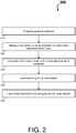
- FIG. 2 depicts a laser direct metal deposition process flow 200 on a graphite substrate in accordance with one or more embodiments.
- the laser direct metal deposition process flow 200 is a deposit of metal on graphite forms by covering a graphite substrate with a thin metal sheath before the metal deposition.
- the laser direct metal deposition process flow 200 beings at block 210, where a graphite substrate (e.g., the workpiece 110 of FIG. 1 ) is prepared.
- the graphite substrate can be prepared with or without metal plating.
- the metal plating can include metals, such as Nickel or Chromium, to prevent oxidation and to get a metal coating that enables a bonding while performing the remaining operations of the laser direct metal deposition process flow 200.
- an outer sheath is made to act as interface for laser metal deposition molten pool (e.g., the melt pool 150 of FIG. 1 ).
- a metallic interface metal such as thin Nickel sheet metal or foil of suitable thickness, is selected and pre-formed to make an outer sleeve/sheath cover.
- the outer sheath is assembled by sliding over the graphite substrate.
- a Nickel sheath (or sleeve) is placed on the graphite substrate.
- the outer sheath's thickness can be determined based on a thickness of the melt pool 150 of FIG. 1 required for a particular laser power in a laser metal deposition process specific to the workpiece 110 of FIG. 1 .
- the sheath itself can also be made separately from metal powders (e.g. Nickel) using a laser metal deposition process.
- the outer sheath can be held in place over the graphite substrate during laser direct metal deposition process. For instance, mechanically restraining the metal sheath 310, 410 of FIGS. 3 and 4 onto the graphite substrate 320, 420 of FIGS. 3 and 4 enables all surfaces to be in perfect contact.
- the exposed graphite surfaces (shown in FIGS. 3 and 4 ) are covered with end caps for further deposition.
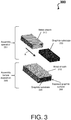
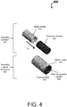
- FIGS. 3 and 4 example schematics 300 and 400 of a metallic interface held in position are shown in accordance with one or more embodiments.
- the schematic 300 depicts a metal sheath 310 and a graphite substrate 320 (e.g., a rectangular box shape).
- the metal sheath 310 slides over the graphite substrate 320 (as shown by Arrow A) to create the assembly before the deposition 398 with an exposed graphite surface 399.
- the schematic 400 depicts a metal sheath 410 and a graphite substrate 420 (e.g., a cylindrical shape).
- the metal sheath 410 slides over the graphite substrate 420 (as shown by Arrow B) to create the assembly before the deposition 498 with an exposed graphite surface 499. Note that while two configurations are shown in FIGS. 3 and 4 , other complex shapes are contemplated.
- laser scanning of outer sheath is performed once the metallic interface/sheath is held in place over the graphite substrate.
- the laser scanning can be done on the sheath surface with pre-defined laser power to melt the metallic interface/sheath so that it forms a bond with the (e.g., Nickel) plating on the graphite substrate (e.g., the workpiece 110 of FIG. 1 ).
- the laser scanning ensures localized melting of the sheath and enables contact between the sheath and graphite substrate.
- the laser scanning scheme also enables/ensures the entrapped air between the metallic interface and graphite surface to escape (e.g., the surface of the outer sheath and the graphite surface escapes). And if required, the entrapped air also can be removed by doing the laser scan in vacuum; thereby continuous or full contact can be achieved between the molten sheath and graphite.
- a metal powder stream e.g., the powder stream 160 of FIG. 1
- a laser metal deposition over the graphite with the outer sheath is performed.
- the assembly from block 250 can be verified for proper interface contact by X-ray or any other means.
- the meal deposition can be carried out in further layers with the standard laser deposition process.
- FIG. 5 depicts a schematic 500 of an application of annealed pyrolitic graphite in Pitot tube 501 in accordance with one or more embodiments.
- the schematic 500 a perspective view 510 and a cross-sectional view 530.
- the laser direct metal deposition process flow 200 on a graphite substrate can be applied in manufacturing of hybrid material air data probes, heat sinks, electronic enclosure, and the like that require enhanced thermal properties.
- the technical effects and benefits of the one or more embodiments herein include no annealed pyrolitic graphite oxidation due to coated/electroplated annealed pyrolitic graphite surface during laser direct metal deposition process; continuous or full surface to surface contact between graphite substrate and encapsulate material with complex shapes; and high thermal conductivity of the hybrid structure (with the annealed Pyrolitic graphite). Note that the heating performance method can also be applied to materials that do not create a melt pool with a laser application.
Landscapes
- Engineering & Computer Science (AREA)
- Physics & Mathematics (AREA)
- Mechanical Engineering (AREA)
- Optics & Photonics (AREA)
- Chemical & Material Sciences (AREA)
- Plasma & Fusion (AREA)
- Materials Engineering (AREA)
- Organic Chemistry (AREA)
- Metallurgy (AREA)
- Chemical Kinetics & Catalysis (AREA)
- Manufacturing & Machinery (AREA)
- Laser Beam Processing (AREA)
- Other Surface Treatments For Metallic Materials (AREA)
Abstract
Description
- Presently, during additive manufacturing, laser metal deposition trials of hybrid material Pitot tube, it is found that metal deposition is not happening over the graphite substrate. The melt pool cannot be created on a graphite surface at atmospheric pressure since graphite will sublimate at high temperatures instead of melting. Thus, there is a need for a reliable method to deposit metal over graphite substrate.
- In accordance with an aspect of the present invention, a laser direct metal deposition method for a graphite substrate is provided. The laser direct metal deposition method includes creating an assembly by sliding an outer sheath over the graphite substrate. Further, laser direct metal deposition method includes performing a laser scanning of the outer sheath and performing a laser metal deposition over the graphite substrate with the outer sheath.
- In accordance with one or more embodiments of the laser direct metal deposition method embodiment above, the graphite substrate can be prepared without metal plating.
- In accordance with one or more embodiments of the laser direct metal deposition method embodiment above, the graphite substrate can be prepared by plating with one or more metals including Nickel or Chromium to prevent oxidation.
- In accordance with one or more embodiments of any of the laser direct metal deposition method embodiments above, the outer sheath can act as interface for a laser metal deposition molten pool.
- In accordance with one or more embodiments of any of the laser direct metal deposition method embodiments above, the outer sheath can include a metallic interface metal.
- In accordance with one or more embodiments of any of the laser direct metal deposition method embodiments above, a thickness of the outer sheath can be determined based on a thickness of a melt pool.
- In accordance with one or more embodiments of any of the laser direct metal deposition method embodiments above, the outer sheath can be mechanically restrained in place over the graphite substrate during the laser direct metal deposition process enable full contact between the outer sheath and the graphite substrate.
- In accordance with one or more embodiments of any of the laser direct metal deposition method embodiments above, the graphite substrate can include a rectangular box shape or a cylindrical shape.
- In accordance with one or more embodiments of any of the laser direct metal deposition method embodiments above, the laser scanning of outer sheath can be performed on a surface of the outer sheath with a pre-defined laser power to melt the surface and form a bond with the graphite substrate.
- In accordance with one or more embodiments of any of the laser direct metal deposition method embodiments above, the laser scanning can enable entrapped air between the surface of the outer sheath and the graphite surface escapes.
- In accordance with one or more embodiments, any of the above method embodiments can be implemented as a system and/or apparatus.
- The following descriptions should not be considered limiting in any way. With reference to the accompanying drawings, like elements are numbered alike:
-
FIG. 1 depicts a schematic of laser metal deposition in accordance with one or more embodiments; -
FIG. 2 depicts a laser direct metal deposition process flow on graphite substrate in accordance with one or more embodiments; -
FIG. 3 depicts a schematic of a metallic interface held in position in accordance with one or more embodiments; -
FIG. 4 depicts a schematic of a metallic interface held in position in accordance with one or more embodiments; and -
FIG. 5 depicts a schematic of an application of annealed pyrolitic graphite in Pitot tube in accordance with one or more embodiments. - A detailed description of one or more embodiments of the disclosed apparatus and method are presented herein by way of exemplification and not limitation with reference to the Figures.
-
FIG. 1 depicts a schematic 100 of laser direct metal deposition in accordance with one or more embodiments. As shown inFIG. 1 , the schematic comprises aworkpiece 110, afusion zone 120, adeposit zone 130, and amelt pool 150. Further, the schematic also comprises alaser beam 140, apowder stream 160, and ashield gas 170. The operations of the schematic 100 are described with respect toFIGS. 2-5 . -
FIG. 2 depicts a laser direct metal deposition process flow 200 on a graphite substrate in accordance with one or more embodiments. In general, the laser direct metaldeposition process flow 200 is a deposit of metal on graphite forms by covering a graphite substrate with a thin metal sheath before the metal deposition. - The laser direct metal deposition process flow 200 beings at
block 210, where a graphite substrate (e.g., theworkpiece 110 ofFIG. 1 ) is prepared. The graphite substrate can be prepared with or without metal plating. Further, the metal plating can include metals, such as Nickel or Chromium, to prevent oxidation and to get a metal coating that enables a bonding while performing the remaining operations of the laser direct metaldeposition process flow 200. - At
block 220, an outer sheath is made to act as interface for laser metal deposition molten pool (e.g., themelt pool 150 ofFIG. 1 ). A metallic interface metal, such as thin Nickel sheet metal or foil of suitable thickness, is selected and pre-formed to make an outer sleeve/sheath cover. - At
block 230, the outer sheath is assembled by sliding over the graphite substrate. For instance, a Nickel sheath (or sleeve) is placed on the graphite substrate. The outer sheath's thickness can be determined based on a thickness of themelt pool 150 ofFIG. 1 required for a particular laser power in a laser metal deposition process specific to theworkpiece 110 ofFIG. 1 . The sheath itself can also be made separately from metal powders (e.g. Nickel) using a laser metal deposition process. Note that the outer sheath can be held in place over the graphite substrate during laser direct metal deposition process. For instance, mechanically restraining themetal sheath FIGS. 3 and4 onto thegraphite substrate FIGS. 3 and4 enables all surfaces to be in perfect contact. The exposed graphite surfaces (shown inFIGS. 3 and4 ) are covered with end caps for further deposition. - Turning now to
FIGS. 3 and4 ,example schematics metal sheath 310 and a graphite substrate 320 (e.g., a rectangular box shape). During anassembly operation 351, themetal sheath 310 slides over the graphite substrate 320 (as shown by Arrow A) to create the assembly before thedeposition 398 with an exposedgraphite surface 399. The schematic 400 depicts ametal sheath 410 and a graphite substrate 420 (e.g., a cylindrical shape). During anassembly operation 451, themetal sheath 410 slides over the graphite substrate 420 (as shown by Arrow B) to create the assembly before thedeposition 498 with an exposedgraphite surface 499. Note that while two configurations are shown inFIGS. 3 and4 , other complex shapes are contemplated. - At
block 240, laser scanning of outer sheath is performed once the metallic interface/sheath is held in place over the graphite substrate. For instance, the laser scanning can be done on the sheath surface with pre-defined laser power to melt the metallic interface/sheath so that it forms a bond with the (e.g., Nickel) plating on the graphite substrate (e.g., theworkpiece 110 ofFIG. 1 ). In the case of graphite substrate without the metallic coating, the laser scanning ensures localized melting of the sheath and enables contact between the sheath and graphite substrate. The laser scanning scheme also enables/ensures the entrapped air between the metallic interface and graphite surface to escape (e.g., the surface of the outer sheath and the graphite surface escapes). And if required, the entrapped air also can be removed by doing the laser scan in vacuum; thereby continuous or full contact can be achieved between the molten sheath and graphite. A metal powder stream (e.g., thepowder stream 160 ofFIG. 1 ) could also be activated at a lesser flow rate while doing the melting of the metallic interface by laser scanning process. - At
block 250, a laser metal deposition over the graphite with the outer sheath is performed. The assembly fromblock 250 can be verified for proper interface contact by X-ray or any other means. Thereafter, the meal deposition can be carried out in further layers with the standard laser deposition process. -
FIG. 5 depicts a schematic 500 of an application of annealed pyrolitic graphite in Pitottube 501 in accordance with one or more embodiments. The schematic 500 a perspective view 510 and across-sectional view 530. In thecross-sectional view 530, inserts 560 of graphite substrates within thePitot tube 501 according to embodiments herein. - In accordance with one or more embodiments, the laser direct metal
deposition process flow 200 on a graphite substrate can be applied in manufacturing of hybrid material air data probes, heat sinks, electronic enclosure, and the like that require enhanced thermal properties. The technical effects and benefits of the one or more embodiments herein include no annealed pyrolitic graphite oxidation due to coated/electroplated annealed pyrolitic graphite surface during laser direct metal deposition process; continuous or full surface to surface contact between graphite substrate and encapsulate material with complex shapes; and high thermal conductivity of the hybrid structure (with the annealed Pyrolitic graphite). Note that the heating performance method can also be applied to materials that do not create a melt pool with a laser application. - The term "about" is intended to include the degree of error associated with measurement of the particular quantity based upon the equipment available at the time of filing the application.
- The terminology used herein is for the purpose of describing particular embodiments only and is not intended to be limiting of the present disclosure. As used herein, the singular forms "a", "an" and "the" are intended to include the plural forms as well, unless the context clearly indicates otherwise. It will be further understood that the terms "comprises" and/or "comprising," when used in this specification, specify the presence of stated features, integers, steps, operations, elements, and/or components, but do not preclude the presence or addition of one or more other features, integers, steps, operations, element components, and/or groups thereof.
- While the present disclosure has been described with reference to an exemplary embodiment or embodiments, it will be understood by those skilled in the art that various changes may be made and equivalents may be substituted for elements thereof without departing from the scope of the present disclosure. In addition, many modifications may be made to adapt a particular situation or material to the teachings of the present disclosure without departing from the essential scope thereof. Therefore, it is intended that the present disclosure not be limited to the particular embodiment disclosed as the best mode contemplated for carrying out this present disclosure, but that the present disclosure will include all embodiments falling within the scope of the claims.
Claims (11)
- A laser direct metal deposition method for a graphite substrate (110, 320, 420), the laser direct metal deposition method comprising:creating an assembly (398, 498) by sliding an outer sheath (310, 410) over the graphite substrate (110, 320, 420);performing a laser scanning of the outer sheath (310, 410); andperforming a laser metal deposition over the graphite substrate (110, 320, 420) with the outer sheath (310, 410).
- An apparatus constructed from a laser direct metal deposition method for a graphite substrate (110, 320, 420), the apparatus comprising:an assembly (398, 498) created by sliding an outer sheath (310, 410) over the graphite substrate (110, 320, 420); anda laser metal deposition over the graphite substrate (110, 320, 420) with the outer sheath (310, 410), wherein the outer sheath (310, 410) is laser scanned prior to adding the laser metal deposition to the assembly (398, 498).
- The method or apparatus of claim 1 or 2, wherein the graphite substrate (110, 320, 420) is prepared without metal plating.
- The method or apparatus of claim 1 or 2, wherein the graphite substrate (110, 320, 420) is prepared by plating with one or more metals including Nickel or Chromium to prevent oxidation.
- The method or apparatus of any preceding claim, wherein the outer sheath (310, 410) acts as interface for a laser metal deposition molten pool.
- The method or apparatus of any preceding claim, wherein the outer sheath (310, 410) comprises a metallic interface metal.
- The method or apparatus of any preceding claim, wherein a thickness of the outer sheath (310, 410) is determined based on a thickness of a melt pool (150).
- The method or apparatus of any preceding claim, wherein the outer sheath (310, 410) is mechanically restrained in place over the graphite substrate (110, 320, 420) during the laser direct metal deposition process to enable full contact between the outer sheath (310, 410) and the graphite substrate (110, 320, 420).
- The method or apparatus of any preceding claim, wherein the graphite substrate (110, 320, 420) comprises a rectangular box shape or a cylindrical shape.
- The method or apparatus of any preceding claim, wherein the laser scanning of the outer sheath (310, 410) is performed on a surface of the outer sheath (310, 410) with a pre-defined laser power to melt the surface and form a bond with the graphite substrate (110, 320, 420).
- The method or apparatus of any preceding claim, wherein the laser scanning enables entrapped air between a/the surface of the outer sheath (310, 410) and a surface of the graphite substrate (110, 320, 420) to escape.
Applications Claiming Priority (1)
| Application Number | Priority Date | Filing Date | Title |
|---|---|---|---|
| IN201811034577 | 2018-09-13 |
Publications (2)
| Publication Number | Publication Date |
|---|---|
| EP3623099A1 true EP3623099A1 (en) | 2020-03-18 |
| EP3623099B1 EP3623099B1 (en) | 2021-04-21 |
Family
ID=67928744
Family Applications (1)
| Application Number | Title | Priority Date | Filing Date |
|---|---|---|---|
| EP19196766.0A Active EP3623099B1 (en) | 2018-09-13 | 2019-09-11 | Laser metal deposition methodology on graphite substrates for aerospace components |
Country Status (2)
| Country | Link |
|---|---|
| US (1) | US10640860B2 (en) |
| EP (1) | EP3623099B1 (en) |
Families Citing this family (3)
| Publication number | Priority date | Publication date | Assignee | Title |
|---|---|---|---|---|
| CA3067550A1 (en) * | 2019-01-17 | 2020-07-17 | Goodrich Corporation | Pitot tube |
| US11131686B2 (en) * | 2019-02-01 | 2021-09-28 | Rosemount Aerospace Inc. | Process for manufacturing a pitot tube having a graphite insert embedded therein |
| US12214887B2 (en) | 2022-01-27 | 2025-02-04 | Hamilton Sundstrand Corporation | Environmental control system including humidity sensor |
Citations (7)
| Publication number | Priority date | Publication date | Assignee | Title |
|---|---|---|---|---|
| EP3048408A1 (en) * | 2015-01-15 | 2016-07-27 | Hamilton Sundstrand Space Systems International, Inc. | Composite passive heat sink system and method |
| EP3076185A1 (en) * | 2015-04-02 | 2016-10-05 | Rosemount Aerospace Inc. | Corrosion-resistant heated air data probe |
| EP3133403A1 (en) * | 2015-08-20 | 2017-02-22 | Honeywell International Inc. | Systems and methods for additive manufacturing for air data probes |
| FR3042065A1 (en) * | 2015-10-06 | 2017-04-07 | Thales Sa | METHOD OF MANUFACTURING THERMAL DRAIN AND THERMAL DRAIN |
| EP3190419A1 (en) * | 2016-01-08 | 2017-07-12 | Honeywell International Inc. | Probe tip for air data probe |
| EP3199955A1 (en) * | 2016-01-29 | 2017-08-02 | Goodrich Aerospace Services Private Limited | Pitot tube with thermally conductive insert |
| US20180112938A1 (en) * | 2016-10-26 | 2018-04-26 | Goodrich Aerospace Services Private Limited | Die-cast bodies with thermal conductive inserts |
Family Cites Families (4)
| Publication number | Priority date | Publication date | Assignee | Title |
|---|---|---|---|---|
| US20070141375A1 (en) | 2005-12-20 | 2007-06-21 | Budinger David E | Braze cladding for direct metal laser sintered materials |
| US20090047439A1 (en) * | 2007-08-16 | 2009-02-19 | Withers James C | Method and apparatus for manufacturing porous articles |
| CN105228788A (en) | 2012-11-29 | 2016-01-06 | 康宁股份有限公司 | For sacrifice cover layer and the method thereof of laser drill base material |
| US20180099358A1 (en) | 2016-10-07 | 2018-04-12 | General Electric Company | Metallic Sleeve For Reducing Distortion In Additive Manufacturing |
-
2018
- 2018-10-30 US US16/175,125 patent/US10640860B2/en active Active
-
2019
- 2019-09-11 EP EP19196766.0A patent/EP3623099B1/en active Active
Patent Citations (7)
| Publication number | Priority date | Publication date | Assignee | Title |
|---|---|---|---|---|
| EP3048408A1 (en) * | 2015-01-15 | 2016-07-27 | Hamilton Sundstrand Space Systems International, Inc. | Composite passive heat sink system and method |
| EP3076185A1 (en) * | 2015-04-02 | 2016-10-05 | Rosemount Aerospace Inc. | Corrosion-resistant heated air data probe |
| EP3133403A1 (en) * | 2015-08-20 | 2017-02-22 | Honeywell International Inc. | Systems and methods for additive manufacturing for air data probes |
| FR3042065A1 (en) * | 2015-10-06 | 2017-04-07 | Thales Sa | METHOD OF MANUFACTURING THERMAL DRAIN AND THERMAL DRAIN |
| EP3190419A1 (en) * | 2016-01-08 | 2017-07-12 | Honeywell International Inc. | Probe tip for air data probe |
| EP3199955A1 (en) * | 2016-01-29 | 2017-08-02 | Goodrich Aerospace Services Private Limited | Pitot tube with thermally conductive insert |
| US20180112938A1 (en) * | 2016-10-26 | 2018-04-26 | Goodrich Aerospace Services Private Limited | Die-cast bodies with thermal conductive inserts |
Also Published As
| Publication number | Publication date |
|---|---|
| US10640860B2 (en) | 2020-05-05 |
| EP3623099B1 (en) | 2021-04-21 |
| US20200087769A1 (en) | 2020-03-19 |
Similar Documents
| Publication | Publication Date | Title |
|---|---|---|
| EP3623099B1 (en) | Laser metal deposition methodology on graphite substrates for aerospace components | |
| EP3135408B1 (en) | Powder-bed additive manufacturing device and method | |
| US4488673A (en) | Direct metal brazing to cermet feedthroughs | |
| US20170263586A1 (en) | Methods and apparatuses for high temperature bonding and bonded substrates having variable porosity distribution formed therefrom | |
| JPH05134067A (en) | Manufacture of heat-receiving plate having cooling structure | |
| EP3914408A1 (en) | Multi-metallic articles of manufacture | |
| WO2016030654A1 (en) | A mould for use in a hot isostatic press | |
| EP1936007A2 (en) | Microwave process for forming a coating | |
| EP3096910B1 (en) | Additive manufacturing an object from material with a selective diffusion barrier | |
| CN104821523A (en) | Manufacturing method of metal composite pipe | |
| HU178946B (en) | Process for joining details made of aluminium and irom alloys | |
| Choubey et al. | On identifying the suitable substrate medium for induction heating-based metal wire additive manufacturing | |
| KR20210143161A (en) | Manufacturing method of cylindrical sputtering target | |
| KR102217603B1 (en) | A metal part comprising electronic components with non-continuous microstructure layer and its manufacturing method | |
| KR20190103531A (en) | Method for manufacturing metal parts embedded with electronic components and electronic components embedded metal part manufactured by the method | |
| EP4021726B1 (en) | A powder bed additive manufacturing machine | |
| US20150342070A1 (en) | Method of making an object with a metal-non-metal seal | |
| JPH08250465A (en) | Electrode cover for semiconductor plasma processing equipment | |
| CN114566414A (en) | Vacuum device | |
| CN113523488A (en) | Semi-rigid cable welding explosion-proof treatment method | |
| US20160068966A1 (en) | Laser cladding alloy for aluminum injection molds | |
| JPH027379A (en) | Manufacture of heating plate | |
| JPH0147277B2 (en) | ||
| US20240375132A1 (en) | Droplet applicator and method for generating molten metal droplets | |
| Hsu et al. | Fluxless tin bonding of silicon chips to iron substrates |
Legal Events
| Date | Code | Title | Description |
|---|---|---|---|
| PUAI | Public reference made under article 153(3) epc to a published international application that has entered the european phase |
Free format text: ORIGINAL CODE: 0009012 |
|
| STAA | Information on the status of an ep patent application or granted ep patent |
Free format text: STATUS: THE APPLICATION HAS BEEN PUBLISHED |
|
| AK | Designated contracting states |
Kind code of ref document: A1 Designated state(s): AL AT BE BG CH CY CZ DE DK EE ES FI FR GB GR HR HU IE IS IT LI LT LU LV MC MK MT NL NO PL PT RO RS SE SI SK SM TR |
|
| AX | Request for extension of the european patent |
Extension state: BA ME |
|
| STAA | Information on the status of an ep patent application or granted ep patent |
Free format text: STATUS: REQUEST FOR EXAMINATION WAS MADE |
|
| 17P | Request for examination filed |
Effective date: 20200916 |
|
| RBV | Designated contracting states (corrected) |
Designated state(s): AL AT BE BG CH CY CZ DE DK EE ES FI FR GB GR HR HU IE IS IT LI LT LU LV MC MK MT NL NO PL PT RO RS SE SI SK SM TR |
|
| GRAP | Despatch of communication of intention to grant a patent |
Free format text: ORIGINAL CODE: EPIDOSNIGR1 |
|
| STAA | Information on the status of an ep patent application or granted ep patent |
Free format text: STATUS: GRANT OF PATENT IS INTENDED |
|
| RIC1 | Information provided on ipc code assigned before grant |
Ipc: B23P 15/00 20060101AFI20201014BHEP Ipc: B23K 26/34 20140101ALI20201014BHEP Ipc: B33Y 30/00 20150101ALI20201014BHEP Ipc: B23K 26/00 20140101ALI20201014BHEP Ipc: B23K 26/08 20140101ALI20201014BHEP Ipc: B33Y 10/00 20150101ALI20201014BHEP Ipc: B23K 26/14 20140101ALI20201014BHEP Ipc: B23K 26/144 20140101ALI20201014BHEP Ipc: B23K 26/12 20140101ALI20201014BHEP Ipc: B23K 103/00 20060101ALN20201014BHEP Ipc: B23K 103/18 20060101ALN20201014BHEP |
|
| INTG | Intention to grant announced |
Effective date: 20201113 |
|
| GRAS | Grant fee paid |
Free format text: ORIGINAL CODE: EPIDOSNIGR3 |
|
| GRAA | (expected) grant |
Free format text: ORIGINAL CODE: 0009210 |
|
| STAA | Information on the status of an ep patent application or granted ep patent |
Free format text: STATUS: THE PATENT HAS BEEN GRANTED |
|
| AK | Designated contracting states |
Kind code of ref document: B1 Designated state(s): AL AT BE BG CH CY CZ DE DK EE ES FI FR GB GR HR HU IE IS IT LI LT LU LV MC MK MT NL NO PL PT RO RS SE SI SK SM TR |
|
| REG | Reference to a national code |
Ref country code: GB Ref legal event code: FG4D |
|
| REG | Reference to a national code |
Ref country code: CH Ref legal event code: EP |
|
| REG | Reference to a national code |
Ref country code: DE Ref legal event code: R096 Ref document number: 602019004045 Country of ref document: DE Ref country code: IE Ref legal event code: FG4D |
|
| REG | Reference to a national code |
Ref country code: AT Ref legal event code: REF Ref document number: 1384117 Country of ref document: AT Kind code of ref document: T Effective date: 20210515 |
|
| REG | Reference to a national code |
Ref country code: LT Ref legal event code: MG9D |
|
| REG | Reference to a national code |
Ref country code: AT Ref legal event code: MK05 Ref document number: 1384117 Country of ref document: AT Kind code of ref document: T Effective date: 20210421 |
|
| REG | Reference to a national code |
Ref country code: NL Ref legal event code: MP Effective date: 20210421 |
|
| PG25 | Lapsed in a contracting state [announced via postgrant information from national office to epo] |
Ref country code: LT Free format text: LAPSE BECAUSE OF FAILURE TO SUBMIT A TRANSLATION OF THE DESCRIPTION OR TO PAY THE FEE WITHIN THE PRESCRIBED TIME-LIMIT Effective date: 20210421 Ref country code: HR Free format text: LAPSE BECAUSE OF FAILURE TO SUBMIT A TRANSLATION OF THE DESCRIPTION OR TO PAY THE FEE WITHIN THE PRESCRIBED TIME-LIMIT Effective date: 20210421 Ref country code: FI Free format text: LAPSE BECAUSE OF FAILURE TO SUBMIT A TRANSLATION OF THE DESCRIPTION OR TO PAY THE FEE WITHIN THE PRESCRIBED TIME-LIMIT Effective date: 20210421 Ref country code: NL Free format text: LAPSE BECAUSE OF FAILURE TO SUBMIT A TRANSLATION OF THE DESCRIPTION OR TO PAY THE FEE WITHIN THE PRESCRIBED TIME-LIMIT Effective date: 20210421 Ref country code: AT Free format text: LAPSE BECAUSE OF FAILURE TO SUBMIT A TRANSLATION OF THE DESCRIPTION OR TO PAY THE FEE WITHIN THE PRESCRIBED TIME-LIMIT Effective date: 20210421 Ref country code: BG Free format text: LAPSE BECAUSE OF FAILURE TO SUBMIT A TRANSLATION OF THE DESCRIPTION OR TO PAY THE FEE WITHIN THE PRESCRIBED TIME-LIMIT Effective date: 20210721 |
|
| PG25 | Lapsed in a contracting state [announced via postgrant information from national office to epo] |
Ref country code: NO Free format text: LAPSE BECAUSE OF FAILURE TO SUBMIT A TRANSLATION OF THE DESCRIPTION OR TO PAY THE FEE WITHIN THE PRESCRIBED TIME-LIMIT Effective date: 20210721 Ref country code: LV Free format text: LAPSE BECAUSE OF FAILURE TO SUBMIT A TRANSLATION OF THE DESCRIPTION OR TO PAY THE FEE WITHIN THE PRESCRIBED TIME-LIMIT Effective date: 20210421 Ref country code: PL Free format text: LAPSE BECAUSE OF FAILURE TO SUBMIT A TRANSLATION OF THE DESCRIPTION OR TO PAY THE FEE WITHIN THE PRESCRIBED TIME-LIMIT Effective date: 20210421 Ref country code: SE Free format text: LAPSE BECAUSE OF FAILURE TO SUBMIT A TRANSLATION OF THE DESCRIPTION OR TO PAY THE FEE WITHIN THE PRESCRIBED TIME-LIMIT Effective date: 20210421 Ref country code: PT Free format text: LAPSE BECAUSE OF FAILURE TO SUBMIT A TRANSLATION OF THE DESCRIPTION OR TO PAY THE FEE WITHIN THE PRESCRIBED TIME-LIMIT Effective date: 20210823 Ref country code: RS Free format text: LAPSE BECAUSE OF FAILURE TO SUBMIT A TRANSLATION OF THE DESCRIPTION OR TO PAY THE FEE WITHIN THE PRESCRIBED TIME-LIMIT Effective date: 20210421 Ref country code: IS Free format text: LAPSE BECAUSE OF FAILURE TO SUBMIT A TRANSLATION OF THE DESCRIPTION OR TO PAY THE FEE WITHIN THE PRESCRIBED TIME-LIMIT Effective date: 20210821 Ref country code: GR Free format text: LAPSE BECAUSE OF FAILURE TO SUBMIT A TRANSLATION OF THE DESCRIPTION OR TO PAY THE FEE WITHIN THE PRESCRIBED TIME-LIMIT Effective date: 20210722 |
|
| REG | Reference to a national code |
Ref country code: DE Ref legal event code: R097 Ref document number: 602019004045 Country of ref document: DE |
|
| PG25 | Lapsed in a contracting state [announced via postgrant information from national office to epo] |
Ref country code: ES Free format text: LAPSE BECAUSE OF FAILURE TO SUBMIT A TRANSLATION OF THE DESCRIPTION OR TO PAY THE FEE WITHIN THE PRESCRIBED TIME-LIMIT Effective date: 20210421 Ref country code: EE Free format text: LAPSE BECAUSE OF FAILURE TO SUBMIT A TRANSLATION OF THE DESCRIPTION OR TO PAY THE FEE WITHIN THE PRESCRIBED TIME-LIMIT Effective date: 20210421 Ref country code: SK Free format text: LAPSE BECAUSE OF FAILURE TO SUBMIT A TRANSLATION OF THE DESCRIPTION OR TO PAY THE FEE WITHIN THE PRESCRIBED TIME-LIMIT Effective date: 20210421 Ref country code: DK Free format text: LAPSE BECAUSE OF FAILURE TO SUBMIT A TRANSLATION OF THE DESCRIPTION OR TO PAY THE FEE WITHIN THE PRESCRIBED TIME-LIMIT Effective date: 20210421 Ref country code: CZ Free format text: LAPSE BECAUSE OF FAILURE TO SUBMIT A TRANSLATION OF THE DESCRIPTION OR TO PAY THE FEE WITHIN THE PRESCRIBED TIME-LIMIT Effective date: 20210421 Ref country code: SM Free format text: LAPSE BECAUSE OF FAILURE TO SUBMIT A TRANSLATION OF THE DESCRIPTION OR TO PAY THE FEE WITHIN THE PRESCRIBED TIME-LIMIT Effective date: 20210421 Ref country code: RO Free format text: LAPSE BECAUSE OF FAILURE TO SUBMIT A TRANSLATION OF THE DESCRIPTION OR TO PAY THE FEE WITHIN THE PRESCRIBED TIME-LIMIT Effective date: 20210421 |
|
| PLBE | No opposition filed within time limit |
Free format text: ORIGINAL CODE: 0009261 |
|
| STAA | Information on the status of an ep patent application or granted ep patent |
Free format text: STATUS: NO OPPOSITION FILED WITHIN TIME LIMIT |
|
| 26N | No opposition filed |
Effective date: 20220124 |
|
| REG | Reference to a national code |
Ref country code: BE Ref legal event code: MM Effective date: 20210930 |
|
| PG25 | Lapsed in a contracting state [announced via postgrant information from national office to epo] |
Ref country code: IS Free format text: LAPSE BECAUSE OF FAILURE TO SUBMIT A TRANSLATION OF THE DESCRIPTION OR TO PAY THE FEE WITHIN THE PRESCRIBED TIME-LIMIT Effective date: 20210821 Ref country code: MC Free format text: LAPSE BECAUSE OF FAILURE TO SUBMIT A TRANSLATION OF THE DESCRIPTION OR TO PAY THE FEE WITHIN THE PRESCRIBED TIME-LIMIT Effective date: 20210421 Ref country code: AL Free format text: LAPSE BECAUSE OF FAILURE TO SUBMIT A TRANSLATION OF THE DESCRIPTION OR TO PAY THE FEE WITHIN THE PRESCRIBED TIME-LIMIT Effective date: 20210421 |
|
| PG25 | Lapsed in a contracting state [announced via postgrant information from national office to epo] |
Ref country code: LU Free format text: LAPSE BECAUSE OF NON-PAYMENT OF DUE FEES Effective date: 20210911 Ref country code: IT Free format text: LAPSE BECAUSE OF FAILURE TO SUBMIT A TRANSLATION OF THE DESCRIPTION OR TO PAY THE FEE WITHIN THE PRESCRIBED TIME-LIMIT Effective date: 20210421 Ref country code: IE Free format text: LAPSE BECAUSE OF NON-PAYMENT OF DUE FEES Effective date: 20210911 Ref country code: BE Free format text: LAPSE BECAUSE OF NON-PAYMENT OF DUE FEES Effective date: 20210930 |
|
| REG | Reference to a national code |
Ref country code: CH Ref legal event code: PL |
|
| PG25 | Lapsed in a contracting state [announced via postgrant information from national office to epo] |
Ref country code: CY Free format text: LAPSE BECAUSE OF FAILURE TO SUBMIT A TRANSLATION OF THE DESCRIPTION OR TO PAY THE FEE WITHIN THE PRESCRIBED TIME-LIMIT Effective date: 20210421 |
|
| PG25 | Lapsed in a contracting state [announced via postgrant information from national office to epo] |
Ref country code: LI Free format text: LAPSE BECAUSE OF NON-PAYMENT OF DUE FEES Effective date: 20220930 Ref country code: HU Free format text: LAPSE BECAUSE OF FAILURE TO SUBMIT A TRANSLATION OF THE DESCRIPTION OR TO PAY THE FEE WITHIN THE PRESCRIBED TIME-LIMIT; INVALID AB INITIO Effective date: 20190911 Ref country code: CH Free format text: LAPSE BECAUSE OF NON-PAYMENT OF DUE FEES Effective date: 20220930 |
|
| PG25 | Lapsed in a contracting state [announced via postgrant information from national office to epo] |
Ref country code: MK Free format text: LAPSE BECAUSE OF FAILURE TO SUBMIT A TRANSLATION OF THE DESCRIPTION OR TO PAY THE FEE WITHIN THE PRESCRIBED TIME-LIMIT Effective date: 20210421 |
|
| PG25 | Lapsed in a contracting state [announced via postgrant information from national office to epo] |
Ref country code: MT Free format text: LAPSE BECAUSE OF FAILURE TO SUBMIT A TRANSLATION OF THE DESCRIPTION OR TO PAY THE FEE WITHIN THE PRESCRIBED TIME-LIMIT Effective date: 20210421 |
|
| PGFP | Annual fee paid to national office [announced via postgrant information from national office to epo] |
Ref country code: DE Payment date: 20250820 Year of fee payment: 7 |
|
| PGFP | Annual fee paid to national office [announced via postgrant information from national office to epo] |
Ref country code: GB Payment date: 20250822 Year of fee payment: 7 |
|
| PGFP | Annual fee paid to national office [announced via postgrant information from national office to epo] |
Ref country code: FR Payment date: 20250820 Year of fee payment: 7 |
|
| PG25 | Lapsed in a contracting state [announced via postgrant information from national office to epo] |
Ref country code: TR Free format text: LAPSE BECAUSE OF FAILURE TO SUBMIT A TRANSLATION OF THE DESCRIPTION OR TO PAY THE FEE WITHIN THE PRESCRIBED TIME-LIMIT Effective date: 20210421 |
|
| P01 | Opt-out of the competence of the unified patent court (upc) registered |
Free format text: CASE NUMBER: UPC_APP_0018945_3623099/2025 Effective date: 20251222 |