EP3623038B1 - Membrantaschenmodul mit verdrehsicherem aufbau - Google Patents
Membrantaschenmodul mit verdrehsicherem aufbau Download PDFInfo
- Publication number
- EP3623038B1 EP3623038B1 EP18194151.9A EP18194151A EP3623038B1 EP 3623038 B1 EP3623038 B1 EP 3623038B1 EP 18194151 A EP18194151 A EP 18194151A EP 3623038 B1 EP3623038 B1 EP 3623038B1
- Authority
- EP
- European Patent Office
- Prior art keywords
- permeate
- discs
- membrane
- permeate tube
- finisher
- Prior art date
- Legal status (The legal status is an assumption and is not a legal conclusion. Google has not performed a legal analysis and makes no representation as to the accuracy of the status listed.)
- Active
Links
Images


Classifications
-
- B—PERFORMING OPERATIONS; TRANSPORTING
- B01—PHYSICAL OR CHEMICAL PROCESSES OR APPARATUS IN GENERAL
- B01D—SEPARATION
- B01D63/00—Apparatus in general for separation processes using semi-permeable membranes
- B01D63/08—Flat membrane modules
- B01D63/082—Flat membrane modules comprising a stack of flat membranes
- B01D63/084—Flat membrane modules comprising a stack of flat membranes at least one flow duct intersecting the membranes
-
- B—PERFORMING OPERATIONS; TRANSPORTING
- B01—PHYSICAL OR CHEMICAL PROCESSES OR APPARATUS IN GENERAL
- B01D—SEPARATION
- B01D53/00—Separation of gases or vapours; Recovering vapours of volatile solvents from gases; Chemical or biological purification of waste gases, e.g. engine exhaust gases, smoke, fumes, flue gases, aerosols
- B01D53/22—Separation of gases or vapours; Recovering vapours of volatile solvents from gases; Chemical or biological purification of waste gases, e.g. engine exhaust gases, smoke, fumes, flue gases, aerosols by diffusion
- B01D53/228—Separation of gases or vapours; Recovering vapours of volatile solvents from gases; Chemical or biological purification of waste gases, e.g. engine exhaust gases, smoke, fumes, flue gases, aerosols by diffusion characterised by specific membranes
-
- B—PERFORMING OPERATIONS; TRANSPORTING
- B01—PHYSICAL OR CHEMICAL PROCESSES OR APPARATUS IN GENERAL
- B01D—SEPARATION
- B01D63/00—Apparatus in general for separation processes using semi-permeable membranes
-
- B—PERFORMING OPERATIONS; TRANSPORTING
- B01—PHYSICAL OR CHEMICAL PROCESSES OR APPARATUS IN GENERAL
- B01D—SEPARATION
- B01D2201/00—Details relating to filtering apparatus
- B01D2201/40—Special measures for connecting different parts of the filter
- B01D2201/4046—Means for avoiding false mounting of different parts
-
- B—PERFORMING OPERATIONS; TRANSPORTING
- B01—PHYSICAL OR CHEMICAL PROCESSES OR APPARATUS IN GENERAL
- B01D—SEPARATION
- B01D2313/00—Details relating to membrane modules or apparatus
- B01D2313/02—Specific tightening or locking mechanisms
-
- B—PERFORMING OPERATIONS; TRANSPORTING
- B01—PHYSICAL OR CHEMICAL PROCESSES OR APPARATUS IN GENERAL
- B01D—SEPARATION
- B01D2313/00—Details relating to membrane modules or apparatus
- B01D2313/08—Flow guidance means within the module or the apparatus
- B01D2313/086—Meandering flow path over the membrane
-
- B—PERFORMING OPERATIONS; TRANSPORTING
- B01—PHYSICAL OR CHEMICAL PROCESSES OR APPARATUS IN GENERAL
- B01D—SEPARATION
- B01D2313/00—Details relating to membrane modules or apparatus
- B01D2313/12—Specific discharge elements
Definitions
- the invention relates to membrane modules, in particular membrane pocket modules, which comprise membrane pocket stacks arranged in a housing with at least one feed inlet, at least one retentate outlet and at least one permeate outlet.
- the invention also relates to the use of the membrane module according to the invention for separating liquid and/or gas mixtures.
- membranes Before membranes can be used in technical processes, they must be used in a practically manageable, application-specific arrangement.
- the resulting membrane configurations are referred to as membrane modules.
- an inflow stream (feed) is divided into a concentrate stream (retentate) and a filtrate stream (permeate).
- Flat membranes are used in separation and enrichment technology, e.g. in pocket form.
- pocket membranes also referred to as cushion membranes
- two individual flat membranes with a spacer in between are welded or glued at the edges to form a pocket (a cushion).
- Holes centered in the membrane pocket enable the permeate to be discharged from the interior of the membrane pocket in the direction of a permeate tube which is inserted through the holes.
- the bags are usually stacked to form a module alternately with sealing rings, so that no retentate can get into the permeate pipe.
- the membrane pockets attached around the permeate tube are installed in a housing, whereby the feed can flow around the membrane pockets.
- the permeate of the bags will centrally diverted inwards and discharged via the permeate pipe, which protrudes over cover plates on two end faces of the housing surrounding the membrane pockets and is flanged to this with the help of permeate caps.
- the feed flows around the membrane pockets, preferably in a meandering pattern, caused by deflection disks that are additionally introduced into the membrane stack, which divides the membrane module into subsections (compartment areas).
- such a GS pocket module in which membranes are surrounded by a housing with two end plates, are stacked at a distance from one another and have a central inner bore into which a permeate tube is inserted.
- the end plates (closing disks) seal the housing at its end faces and have an inlet for the feed stream, an outlet for the retentate stream and at least one central outlet for the permate stream (FIG. 9).
- Deflection disks installed in the membrane stack cause the feed to flow around the membrane pockets in a meandering pattern.
- the permeate tube is first connected to one of the cover disks for the housing, the pocket membranes and deflection disks are stacked over the permeate tube and then, placed in a housing, connected to the second cover disk.
- the pocket membranes and deflection disks are then pressed together in the housing to a predetermined size using a press.
- the permeate tube protruding beyond the cover discs is fixed to the cover discs with the help of permeate caps and the pressure of the press is relieved.
- the press is necessary to ensure the meandering flow around the membrane pockets.
- the permeate caps that fix the permeate tube and end caps together can come loose.
- the disadvantage of the known GS membrane modules is that when the permeate caps are tightened again, the cover disks and - caused by the rotation of the cover disks - the membrane stack and the deflection disks twist, which can lead to efficiency losses or even the membrane becoming unusable. Also, the membrane bags cannot be exchanged without a press.
- the object of the present invention is to provide a membrane module of the type mentioned at the outset, in which the membrane pockets can be exchanged in a simple manner.
- the membrane module of the previously known type comprises a housing which is closed in a pressure-tight manner on two end faces by means of sealing disks in order to form a container interior.
- the cover disks comprise at least one feed inlet, at least one retentate outlet and a permeate outlet, with at least one in the container interior Membrane pocket stack is arranged, which has a plurality of lined up and separated from each other by seals membrane pockets, which are plugged onto a permeate tube.
- the permeate tube protrudes beyond the at least one permeate outlet of the cover disks.
- the membrane module according to the invention is characterized in that the permeate tube and the permeate outlet of the cover discs are mutually aligned via a tongue and groove connection.
- the membrane pocket stacks also include deflection disks attached to the permeate tube by means of a central bore, the deflection disks each having recesses for conducting a feed stream from the at least one feed inlet to the at least one retentate outlet in a meandering feed flow, and the permeate tube and deflection disks also having a groove -Spring connection are mutually aligned.
- the deflection disks divide the stack of membrane pockets into compartment areas. According to a preferred embodiment, the number of membrane pockets in the compartment areas subdivided by the deflection disks decreases in the direction from the at least one feed inlet to the at least one retentate outlet.
- a staged cutting disc is further attached to the permeate tube.
- the stepped separating disc can be attached to the permeate pipe, for example by means of an internal thread, by screwing or by welding.
- the stepped separating disk divides the housing into two stages, which - can be fitted with different membrane stacks from the opposite side.
- the steps can also be equipped with membrane stacks on one side, so that one side of the step remains unused.
- the step cutting discs are preferably closed on the inside, so that different Permeate streams can be discharged at different ends of the permeate tube.
- At least one groove is provided in the permeate tube and at least one spring is provided in each case in the permeate outlet of the closing discs and, if present, in the central bore of the deflection discs. More preferably, two grooves are provided in the permeate tube and two springs are provided in the permeate outlet of the end disks and, if present, in the central bores of the deflection disks. More preferably, the grooves in the permeate tube and the tongues are each offset by 180°.
- the housing is a pressure-resistant housing.
- the housing is preferably cylindrical.
- the permeate tube is preferably also cylindrical and protrudes beyond the cover disks of the housing through a central bore hole.
- the structure of the membrane module according to the invention makes it possible to produce the membrane module or to renew the membranes without a press being necessary.
- the membrane module according to the invention can be used to separate liquid and/or gas mixtures.
- the membrane module according to the invention is particularly advantageously used for reducing emissions on breathing lines of storage tanks, as is the case in EP 0 752 974 B1 which is incorporated herein by reference in its entirety.
- the advantage here is that membrane pockets expand, particularly in aggressive environments where the membrane pockets have a short service life easily exchanged without the system having to be sent to the manufacturer.
- the membrane module 1 has a housing 2 which is pressure-tightly sealed on two end faces by means of sealing disks 4 to form a container interior. Bores 41 for the feed inlet or the retentate outlet are located in the end disks 4 . In the cover disks 4 there are also bores for inserting a permeate tube 3, which bores 41, as shown here as an example, are central can be arranged in the cover disks 4.
- the permeate 3 is a both sides mittles Permeatkappe 6 on at least one of the end discs 4 flanged. At least one end of the permeate tube 3 includes a permeate outlet 33.
- One or more deflection pulleys 7 are located in the housing, with the deflection disks 7 each having recesses for conducting a feed flow from the at least one feed inlet 41 to the at least one retentate outlet in a meandering feed flow.
- the deflection disks 7 also have a bore for inserting a permeate tube 3 which can be arranged centrally in the deflection disks 7 .
- a plurality of deflection disks 7, for example two, three, four, five, six, seven, eight, nine or ten or even more deflection disks 7 are arranged in the housing to form a plurality of compartment sections of the membrane module.
- Membrane pocket stacks are arranged between the end disks 4 or between deflection disks 7 and end disks 4 or between the deflection disks 7 , which divide the feed flow into a retentate flow and a permate flow.
- the bags are preferably stacked alternately with sealing rings, so that no retentate can get into the permeate tube.
- the permeate of the bags is diverted inwards centrally and discharged via the permeate pipe.
- FIG. 1 shows an example of an arrangement with a step-separating disk 5, which divides the membrane module into different stages.
- the permeate tube 3 shown has a round permeate tube cross-section 32 which is provided with two grooves 34. FIG which are offset by 180°.
- the permeate tube has a plurality (eg, two, three, four, five, six, seven, eight, nine, ten, eleven, twelve, thirteen, fourteen, fifteen, sixteen or even more) of permeate inlet bores 31 for receiving the permeate stream from the membrane pockets on.
- the permeate tube 3 can be in one piece, so that a stepped separating disc can be fitted and removed again if necessary.
- a two-part permeate tube 3 is shown, in which a stepped separating disk 5 is screwed or welded to the permeate tube 3 by means of an internal thread.
- Deflection sheaves 7 ( 4 ) which subdivide this into compartment areas within a membrane stage, are plugged onto the permeate tube 3 together with the membrane stacks.
- the stage separator disc 5 has a substantially circular cross-section related to the cross-section of the housing, but the cross-section is flattened at one segment of the circle to allow the feed stream to pass from one stage to the next within the housing.
- the step cutting disk has a groove around its periphery into which a gasket, such as a rubber gasket, can be fitted.
- the permeate tube 3 preferably has at least one external thread, preferably at least two external threads, for fixing at least one permeate cap 6 , preferably two permeate caps 6 .
- the permeate tube 3 is in two parts, with one part of the permeate tube 3 having two external threads at its ends, on the one hand for fixing the permeate cap 6 by means of an internal thread in the permeate cap 6 and on the other hand for fixing a stepped separating disk 5 by means of a Internal thread in the stepped separating disc 5 and a second part of the permeate tube 3 via an internal thread of the second part of the permeate tube 3.
- the second part of the permeate tube 3 has an internal thread at one end for fixing the first part of the permeate tube 3 to its external thread and lying in between of the stepped separating disc and at its other end an external thread for fixing the permeate cap 6.
- the permeate outlet 33 takes place centrally via the permeate pipe, for example by applying a negative pressure. If the membrane module 1 is divided into two stages by a stage separating disc 5 , the permeate outlet 33 of the respective stages takes place on opposite sides of the permeate tube 3; consequently, two permeate outlets 33 are provided in this configuration.
- the 3 shows a lens 4 according to the invention, which the housing 2 ( 1 ) terminates on both sides.
- the lens 4 shown has a circular cross-section which is related to the cross-section of the housing.
- a sealing groove 43 for receiving a seal, such as a rubber seal, is preferably provided for gas-tight sealing.
- the closing disk 4 has at least one bore 41 for the inlet of a feed stream or for the outlet of a retenta stream (feed inlet bore/retentate outlet bore 41).
- the cover plate 4 has a hole for inserting the permeate tube 3 ( 1 ), which is arranged centrally in the present case.
- the bore has a circular cross-section that coincides with the permeate tube cross-section 32 ( 2 ) is related.
- the bore has at least one spring 42 for mutual alignment of the permeate tube 3 and cover plate 4 .
- the cover plate 4 shown has a round cross-section which is provided with two springs 42 which are offset by 180°.
- the deflection disk 4 shown has a substantially circular cross-section which is related to the cross-section of the housing, but the cross-section is on a segment of a circle is flattened so that the feed stream can get from one compartment area to the next within the membrane module.
- the deflection disks are preferably installed in the housing with their flattened circular segments offset by 180° in each case, so that the feed flow from the at least one feed inlet 41 ( 1 ) reaches at least one retentate outlet in a meandering feed flow.
- a sealing groove 73 for receiving a seal, such as a rubber seal, is preferably provided for gas-tight sealing.
- the deflection disk 7 has a hole for inserting the permeate tube 3 ( 1 ), which is arranged centrally in the present case.
- the bore has a circular cross-section that coincides with the permeate tube cross-section 32 ( 2 ) is related.
- the bore has at least one spring 72 for mutual alignment of the permeate tube 3 and the deflection disk 7 .
- the deflection disk 7 shown has a round cross-section which is provided with two springs 72 which are offset by 180°.
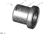
- FIG. 6 shows a permeate cap 6 which serves to flange the permeate tube 3 to the cover disk in a flange area 65 .
- the permeate cap 6 preferably has an internal thread which is related to the external thread at the ends of the permeate tube 3 .
- the permeate cap 6 preferably has a cylindrical permeate cap body 64 in which a keyway 67 is provided for fixing the permeate cap 6 on the permeate tube 3 by means of a key tool.
- the permeate cap body can also be angular, for example hexagonal, so that it can be screwed tight to the permeate pipe with the aid of a spanner tool.
Landscapes
- Chemical & Material Sciences (AREA)
- Chemical Kinetics & Catalysis (AREA)
- Engineering & Computer Science (AREA)
- Analytical Chemistry (AREA)
- General Chemical & Material Sciences (AREA)
- Oil, Petroleum & Natural Gas (AREA)
- Separation Using Semi-Permeable Membranes (AREA)
Description
- Die Erfindung betrifft Membranmodule, insbesondere Membrantaschenmodule, die in einem Gehäuse mit mindestens einem Feedeinlass, mindestens einem Retentatauslass und mindestens einem Permeatauslass angeordnete Membran-Taschenstapel umfassen. Die Erfindung betrifft auch die Verwendung des erfindungsgemäßen Membranmoduls zur Trennung von Flüssigkeits- und/oder Gasgemischen.
- Bevor Membranen in technischen Prozessen nutzbar gemacht werden können, müssen sie in eine praktisch handhabbare, anwendungsspezifische Anordnung eingesetzt werden. Die dabei entstehenden Membrankonfigurationen werden als Membranmodule bezeichnet. In einem Membranmodul wird ein Zulaufstrom (Feed) in einen Konzentratstrom (Retentat) und in einen Filtratstrom (Permeat) aufgeteilt.
- Flachmembranen werden in der Trenn- und Anreicherungstechnik u.a. in Taschenform verwendet. Bei Taschenmembranen (auch als Kissenmembranen bezeichnet) werden zwei einzelne Flachmembranen mit einem dazwischen liegenden Spacer an den Rändern zu einer Tasche (einem Kissen) verschweißt oder verklebt. In der Membrantasche zentrierte Bohrungen ermöglichen die Permeatabfuhr aus dem Innenbereich der Membrantaschen in Richtung eines Permeatrohres, das durch die Bohrungen gesteckt ist. Die Stapelung der Taschen zu einem Modul erfolgt in der Regel abwechselnd mit Dichtringen, so dass kein Retentat in das Permeatrohr gelangen kann.
- Die um das Permeatrohr aufgesteckten Membrantaschen werden in einem Gehäuse installiert, wobei das Feed die Membrantaschen umströmen kann. Das Permeat der Taschen wird zentral nach innen abgeleitet und über das Permeatrohr abgeführt, das über Abschlussscheiben an zwei Stirnseiten des die Membrantaschen umgebenden Gehäuses hinausragt und mit diesem mit Hilfe von Permeatkappen angeflanscht ist. Bei einem GS-Taschenmodul umströmt das Feed die Membrantaschen bevorzugt mäanderförmig, hervorgerufen durch in den Membranstapel zusätzlich eingebrachte Umlenkscheiben, die das Membranmodul in Unterabschnitte (Kompartmentbereiche) unterteilt.
- Aus der
DE-PS 35 07 908 , auf die hier vollständig Bezug genommen wird, ist ein solches GS-Taschenmodul bekannt, wobei Membranen von einem Gehäuse mit zwei Stirnplatten umgeben, im Abstand zueinander gestapelt sind und eine zentrale Innenbohrung aufweisen, in die ein Permeatrohr eingesteckt ist. Die Stirnplatten (Abschlussscheiben) schließen das Gehäuse dichtend an dessen Stirnseiten ab und weisen eine Zuleitung für den Feedstrom, eine Ableitung für den Retentatstrom und mindestens eine zentrale Ableitung für den Permatstrom auf (Fig. 9). In den Membranstapel eingebrachte Umlenkscheiben bewirken eine mäanderförmige Umströmung der Membrantaschen durch das Feed. - Der Aufbau derartiger GS-Taschenmodule wird des Weiteren in T. Melin, R. Rautenbach "Membranverfahren - Grundlagen der Modul- und Anlagenauslegung", 3. Aufl., 2007, Seiten 170 bis 172 und Abb. 5.22. und V. Nitsche et al. "Abtrennung organischer Dämpfe mit Membranen", Chemie Ingenieur Technik (70), Seite 515, Abb. 3 beschrieben, auf die hier vollständig Bezug genommen wird. Weitere Membranmodule mit gestapelten Membrantaschen an einem Permeatrohr sind aus
US5500122 ,US5520807 ,WO9620775 DE3715183 bekannt.EP1475142 beschreibt Membranstapel mit Nut-Feder-Verbindungselementen die die Membranplatten in einem Stapel miteinander verbinden. - Zur Herstellung der Membrantaschenmodule wird zunächst das Permeatrohr mit einer der Abschlussscheiben für das Gehäuse verbunden, die Taschenmembranen und Umlenkscheiben über das Permeatrohr gestapelt und anschließend, in ein Gehäuse eingebracht, mit der zweiten Abschlussscheibe verbunden. Die Taschenmembranen und Umlenkscheiben dann in dem Gehäuse mit Hilfe einer Presse auf eine vorbestimmte Größe zusammengepresst. Das über die Abschlussscheiben hinausragende Permeatrohr wird mit Hilfe von Permeatkappen an den Abschlussscheiben fixiert und der Druck der Presse wird entspannt. Die Presse ist notwendig, um die mäanderförmige Umströmung der Membrantaschen zu gewährleisten.
- Im Betrieb können sich die Permeatkappen lösen, die Permeatrohr und Abschlussscheiben miteinander fixieren. Nachteilig bei den bekannten GS-Membranmodulen ist es, dass sich beim Wiederanziehen der Permeatkappen die Abschlussscheiben und - hervorgerufen durch die Drehung der Abschlussscheiben - die Membranstapel und die Umlenkscheiben verdrehen, was zu Effizienzverlusten bis hin zur Unbrauchbarkeit der Membran führen kann. Auch lassen sich die Membrantaschen nicht ohne Presse austauschen.
- Aufgabe der vorliegenden Erfindung ist es ein Membranmodul der eingangs genannten Art bereitzustellen, bei dem sich die Membrantaschen auf einfache Art austauschen lassen.
- Gelöst wird die Aufgabe durch ein Membranmodul gemäß Patentanspruch 1. Bevorzugte Ausführungsformen sind in den Unteransprüchen wiedergegeben.
- Das Membranmodul der vorbekannten Art umfasst ein Gehäuse, das an zwei Stirnseiten mittels Abschlussscheiben druckdicht zur Bildung eines Behälterinnenraums verschlossen ist. Die Abschlussscheiben umfassen mindestens einen Feedeinlass, mindestens einen Retentatauslass und einen Permeatauslass, wobei in dem Behälterinnenraum mindestens ein Membrantaschenstapel angeordnet ist, der eine Mehrzahl von aneinandergereihten und voneinander durch Dichtungen getrennte Membrantaschen aufweist, die auf ein Permeatrohr augesteckt sind. Das Permeatrohr ragt über den mindestens einen Permeatauslass der Abschlussscheiben hinaus. Das erfindungsgemäße Membranmodul ist dadurch gekennzeichnet, dass Permeatrohr und Permeatauslass der Abschlussscheiben über eine Nut-Federverbindung wechselseitig ausgerichtet sind.
- Gemäß einer Ausführungsform der vorliegenden Erfindung umfassen die Membrantaschenstapel weiterhin mittels einer Zentralbohrung auf das Permeatrohr aufgesteckte Umlenkscheiben, wobei die Umlenkscheiben jeweils Aussparungen zur Leitung eines Feedstroms von dem mindestens einem Feedeinlass zu dem mindestens einen Retentatauslass in mäanderförmiger Feedströmung aufweisen und Permeatrohr und Umlenkscheiben ebenfalls über eine Nut-Federverbindung wechselseitig ausgerichtet sind. Die Umlenkscheiben unterteilen die Membrantaschen-stapel in Kompartmentbereiche. Gemäß einer bevorzugten Ausführungsform nimmt die Anzahl der Membrantaschen in den durch die Umlenkscheiben unterteilten Kompartmentbereichen in Richtung vom mindestens einen Feedeinlass zum mindestens einen Retentatauslass ab.
- Gemäß einer weiteren Ausführungsform der vorliegenden Erfindung ist an dem Permeatrohr weiterhin eine Stufen-Trennscheibe befestigt. Die Stufen-Trennscheibe kann an dem Permeatrohr beispielsweise mittels eines Innengewindes durch anschrauben oder durch anschweißen befestigt werden. Die Stufen-Trennscheibe unterteilt das Gehäuse in zwei Stufen, die - von der jeweils entgegengesetzten Seite mit unterschiedlichen Membranstapeln bestückt werden können. Die Stufen können aber auch einseitig mit Membranstapeln bestückt werden, so dass eine Seite der Stufe ungenutzt bleibt. Die Stufen-Trennscheiben sind bevorzugt innenseitig verschlossen, so dass unterschiedliche Permeatströme an unterschiedlichen Enden des Permeatrohres abgeführt werden können.
- Gemäß einer weiteren Ausführungsform der vorliegenden Erfindung ist im Permeatrohr mindestens eine Nut und jeweils in dem Permeatauslass der Abschlussscheiben sowie, falls vorhanden, in der Zentralbohrung der Umlenkscheiben jeweils mindestens eine Feder vorgesehen. Weiter bevorzugt sind im Permeatrohr zwei Nuten sowie in dem Permeatauslass der Abschlussscheiben und, falls vorhanden, den Zentralbohrungen der Umlenkscheiben jeweils zwei Federn vorgesehen. Weiter bevorzugt sind die Nuten im Permeatrohr und die Federn jeweils um 180° versetzt.
- Gemäß einer weiteren Ausführungsform der vorliegenden Erfindung ist das Gehäuse ein druckresistentes Gehäuse. Das Gehäuse ist vorzugsweise zylinderförmig. Des Weiteren ist bevorzugt auch das Permeatrohr zylinderförmig und ragt über die Abschlussscheiben des Gehäuses durch eine zentrale Bohrung darüber hinaus.
- Es hat sich überraschenderweise gezeigt, dass der Aufbau des erfindungsgemäßen Membranmoduls es ermöglicht das Membranmodul herzustellen oder die Membranen zu erneuern, ohne dass eine Presse notwendig ist.
- Das erfindungsgemäße Membranmodul kann zur Trennung von Flüssigkeits- und/oder Gasgemischen verwendet werden. Besonders vorteilhaft wird das erfindungsgemäße Membranmodul zur Emissionsminderungan Atmungseitungen von Lagertanks verwendet, wie es in der
EP 0 752 974 B1 beschrieben ist, auf die hier vollständig Bezug genommen wird. Vorteilhaft ist dabei, dass sich Membrantaschen insbesondere bei agressiven Umgebungen, bei denen die Membrantaschen eine kurze Lebenszeit haben, auf einfache Art austauschen lassen, ohne dass die Anlage an den Hersteller versendet werden muss. - Die Erfindung wird nunmehr beispielhaft anhand von Figuren näher erläutert, die die Erfindung nicht einschränken und in denen:
-
FIG. 1 eine schematische Darstellung eines erfindungsgemäßen Membranmoduls ist, wobei in der Figur das Gehäuse, Abschlussscheiben, Umlenkscheiben, Permeatrohr und Permatkappen, nicht jedoch Membranstapel dargestellt sind; -
Fig. 2 eine schematische Darstellung eines Permeatrohres mit einer montierten Umlenkscheibe ist, das im erfindungsgemäßen Membranmodul verwendbar ist; -
Fig. 3 eine schematische Darstellung einer Abschlussscheibe ist, die im erfindungsgemäßen Membranmodul verwendbar ist; -
Fig. 4 eine schematische Darstellung einer Umlenkscheibe ist, die im erfindungsgemäßen Membranmodul verwendbar ist; -
Fig. 5 eine schematische Darstellung einer Permeatkappe ist, die im erfindungsgemäßen Membranmodul verwendbar ist. - Zurückkommend auf
Fig. 1 weist das erfindungsgemäße Membranmodul 1 weist ein Gehäuse 2 auf, welches an zwei Stirnseiten mittels Abschlussscheiben 4 druckdicht zur Bildung eines Behälterinnenraums verschlossen ist. In den Abschlussscheiben 4 befinden sich Bohrungen 41 für den Feedeinlass bzw. den Retentatauslass. In den Abschlussscheiben 4 befinden sich des Weiteren Bohrungen zum Durchstecken eines Permeatrohrs 3, welche Bohrungen 41, wie hier beispielshaft gezeigt, zentral in den Abschlussscheiben 4 angeordnet sein können. Das Permeatrohr 3 ist beidseitig mittles einer Permeatkappe 6 an mindestens eine der Abschlussscheiben 4 angeflanscht. Mindestens ein Ende des Permeatrohrs 3 umfasst einen Permeatauslass 33. - Ein oder mehrere Umlenkscheiben 7 (
Fig. 4 ) befinden sich in dem Gehäuse, wobei die Umlenkscheiben 7 jeweils Aussparungen zur Leitung eines Feedstroms von dem mindestens einem Feedeinlass 41 zum mindestens einen Retentatauslass in mäanderförmiger Feedströmung aufweisen. Die Umlenkscheiben 7 weisen ebenfalls eine Bohrung zum Durchstecken eines Permeatrohrs 3 auf, die zentral in den Umlenkscheiben 7 angeordnet sein können. In der Regel ist in dem Gehäuse eine Mehrzahl von Umlenkscheiben 7, beispielsweise zwei, drei, vier, fünf, sechs, sieben, acht, neun oder zehn oder noch mehr Umlenkscheiben 7 zur Bildung einer Mehrzahl von Kompartmentabschnitten des Membranmoduls angeordnet. Zwischen den Abschlussscheiben 4 bzw. zwischen Umlenkscheiben 7 und Abschlussscheiben 4 bzw. zwischen den Umlenkscheiben 7 sind Membrantaschenstapel (nicht gezeigt) angeordnet, die den Feedstrom in einen Retentatstrom und einen Permatstrom aufteilen. Die Stapelung der Taschen erfolgt bevorzugt abwechselnd mit Dichtringen, so dass kein Retentat in das Permeatrohr gelangen kann. Das Permeat der Taschen wird zentral nach innen abgeleitet und über das Permeatrohr abgeführt. -
Fig. 1 zeigt beispielhaft eine Anordnung mit einer Stufen-Trennscheibe 5, die das Membranmodul in unterschiedliche Stufen aufteilt. -
Fig. 2 zeigt eine schematische Darstellung eines erfindungsgemäßen Permeatrohres 3 mit montierter Stufen-Trennscheibe 5. Das gezeigte Permeatrohr 3 weist einen runden Permeatrohrquerschnitt 32 auf, der mit zwei Nuten 34 versehen ist, die um 180° versetzt sind. Das Permeatrohr weist eine Mehrzahl (z.B. zwei, drei, vier, fünf, sechs, sieben, acht, neun, zehn, elf, zwölf, dreizehn, vierzehn, fünfzehn, sechzehn oder noch mehr) von Permeateinlassbohrungen 31 zur Aufnahme des Permeatstroms aus den Membrantaschen auf. Das Permeatrohr 3 kann einteilig oder sein, so dass eine Stufen-Trennscheibe aufgesetzt und bei Bedarf wieder entfernt werden kann. InFig. 2 wird ein zweiteiliges Permeatrohr 3 gezeigt, bei dem eine Stufen-Trennscheibe 5 an das Permeatrohr 3 mittels eines Innengewindes geschraubt oder angeschweißt wird. Umlenkscheiben 7 (Fig. 4 ), die innerhalb einer Membranstufe diese in Kompartmentbereiche unterteilen, werden zusammen mit den Membranstapeln auf das Permeatrohr 3 aufgesteckt. - Bevorzugt weist die Stufen-Trennscheibe 5 einen im Wesentlichen kreisförmigen Querschnitt auf, der mit dem Querschnitt des Gehäuses in Beziehung steht, wobei jedoch der Querschnitt an einem Kreissegment abgeflacht ist, so dass der Feedstrom innerhalb des Gehäuses von einer Stufe in die nächste gelangen kann. Bevorzugt weist die Stufen-Trennscheibe eine Nut um deren Umfang auf, in die eine Dichtung, wie eine Gummidichtung eingesetzt werden kann. Das Permeatrohr 3 weist vorzugsweise mindestens ein Außengewinde, bevorzugt mindestens zwei Außengewinde zur Fixierung mindestens einer Permeatkappe 6, bevorzugt von zwei Permeatkappen 6 auf. Es ist auch vorgesehen, dass das Permeatrohr 3 zweiteilig ist, wobei ein Teil des Permeatrohres 3 an dessen Enden ein zwei Außengewinde, einerseits zur Fixierung der Permeatkappe 6 mittels eines Innengewindes in der Permeatkappe 6 trägt und andererseits zur Fixierung einer Stufen-Trennscheibe 5 mittels eines Innengewindes in der Stufen-Trennscheibe 5 sowie eines zweiten Teils des Permeatrohres 3 über ein Innengewinde des zweiten Teils des Permeatrohres 3. Der zweite Teil des Permeatrohres 3 weist an einem Ende ein Innengewinde zur Fixierung der des ersten Teils des Permeatrohres 3 auf dessen Außengewinde und dazwischenliegend der Stufen Trennscheibe und an seinem anderen Ende ein Außengewinde zur Fixierung der Permeatkappe 6.
- Der Permeatauslass 33 erfolgt zentral über das Permeatrohr, z.B. durch Anlegen eines Unterdrucks. Ist das Membranmodul 1 durch eine Stufen-Trennscheibe 5 in zwei Stufen unterteilt, so erfolgt der Permeatauslass 33 der jeweiligen Stufen an entgegengesetzten Seiten des Permeatrohres 3; mithin sind bei dieser Konfiguration zwei Permeatauslässe 33 vorgesehen.
-
Fig. 3 zeigt eine erfindungsgemäße Abschlussscheibe 4, die das Gehäuse 2 (Fig. 1 ) an beiden Seiten abschließt. Die gezeigte Abschlussscheibe 4 weist einen kreisförmigen Querschnitt auf, der mit dem Querschnitt des Gehäuses in Beziehung steht. Zur gasdichten Abdichtung ist bevorzugt eine Dichtungsnut 43 für die Aufnahme einer Dichtung, wie einer Gummidichtung, vorgesehen. Die Abschlussscheibe 4 weist mindestens eine Bohrung 41 zum Einlass eines Feedstroms bzw. zum Auslass eines Retentastroms auf (Feedeinlassbohrung/Retentatauslassbohrung 41). Des Weiteren weist die Abschlussscheibe 4 eine Bohrung zum Durchstecken des Permeatrohres 3 (Fig. 1 ) auf, die im vorliegenden Fall zentral angeordnet ist. Die Bohrung weist einen kreisförmigen Querschnitt auf, der mit dem Permeatrohrquerschnitt 32 (Fig. 2 ) in Beziehung steht. Zudem weist die Bohrung mindestens eine Feder 42 zur wechselseitigen Ausrichtung von Permeatrohr 3 und Abschlussscheibe 4 auf. Die gezeigte Abschlussscheibe 4 weist einen runden Querschnitt auf, der mit zwei Federn 42 versehen ist, die um 180° versetzt sind. -
Fig. 4 zeigt eine erfindungsgemäße Umlenkscheibe 7, die über das Permeatrohr gesteckt werden kann. Die gezeigte Umlenkscheibe 4 weist einen im Wesentlichen kreisförmigen Querschnitt auf, der mit dem Querschnitt des Gehäuses in Beziehung steht, wobei jedoch der Querschnitt an einem Kreissegment abgeflacht ist, so dass der Feedstrom innerhalb des Membranmoduls von einem Kompartmentbereich in den nächsten gelangen kann. Bevorzugt werden die Umlenkscheiben mit ihren abgeflachten Kreissegmenten um jeweils 180° versetzt in das Gehäuse eingebaut, so dass der Feedstrom von dem mindestens einem Feedeinlass 41 (Fig. 1 ) zum mindestens einen Retentatauslass in mäanderförmiger Feedströmung gelangt. Zur gasdichten Abdichtung ist bevorzugt eine Dichtungsnut 73 für die Aufnahme einer Dichtung, wie einer Gummidichtung, vorgesehen. - Die Umlenkscheibe 7 weist eine Bohrung zum Durchstecken des Permeatrohres 3 (
Fig. 1 ) auf, die im vorliegenden Fall zentral angeordnet ist. Die Bohrung weist einen kreisförmigen Querschnitt auf, der mit dem Permeatrohrquerschnitt 32 (Fig. 2 ) in Beziehung steht. Zudem weist die Bohrung mindestens eine Feder 72 zur wechselseitigen Ausrichtung von Permeatrohr 3 und Umlenkscheibe 7 auf. Die gezeigte Umlenkscheibe 7 weist einen runden Querschnitt auf, der mit zwei Federn 72 versehen ist, die um 180° versetzt sind. - Fig. 6 zeigt eine Permeatkappe 6, die zum Anflanschen des Permeatrohres 3 an der Abschlussscheibe in einem Flanschbereich 65 dient. Die Permeatkappe 6 weist bevorzugt en Innengewinde auf, das mit dem Außengewinde an den Enden des Permeatrohres 3 in Beziehung steht. Die Permeatkappe 6 hat vorzugsweise einen zylindrischen Permeatkappenkörper 64, in dem eine Schlüsselnut 67 zur Fixierung der Permeatkappe 6 auf dem Permeatrohr 3 mittels eines Schlüsselwerkzeugs vorgesehen ist. Alternativ kann der Permeatkappenkörper auch eckig, z.B. sechseckig ausgebildet sein, so dass er mit Hilfe eines Schlüselwerkzeugs an dem Permeatrohr festgeschraubt werden kann.
-
- 1
- Membranmodul
- 2
- Gehäuse
- 3
- Permeatrohr
- 4
- Abschlussscheibe
- 5
- Stufen-Trennscheibe
- 6
- Permeatkappe
- 7
- Umlenkscheibe
- 31
- Permeateinlassbohrungen
- 32
- Permeatrohrquerschnitt
- 33
- Permeatauslass
- 34
- Nut
- 41
- Feedeinlassbohrung/Retentatauslassbohrung
- 42
- Feder
- 43
- Dichtungsnut
- 64
- Permeatkappenkörper
- 65
- Flanschbereich
- 67
- Schlüsselnut
- 72
- Feder
- 73
- Dichtungsnut
Claims (6)
- Membranmodul (1), das ein Gehäuse (2) umfasst, welches an zwei Stirnseiten mittels Abschlussscheiben (4) druckdicht zur Bildung eines Behälterinnenraums verschlossen ist und die Abschlussscheiben (4) mindestens einen Feedeinlass (41), mindestens einen Retentatauslass und mindestens einen Permeatauslass (33) umfassen, wobei in dem Behälterinnenraum mindestens ein Membrantaschenstapel angeordnet ist, der eine Mehrzahl von aneinandergereihten und voneinander durch Dichtungen getrennte Membrantaschen aufweist, die auf ein Permeatrohr (3) aufgesteckt sind, wobei das Permeatrohr über den mindestens einen Permeatauslass (33) der Abschlussscheiben hinausragt, dadurch gekennzeichnet, dass Permeatrohr (3) und Abschlussscheiben (4) über eine Nut-Federverbindung am Permeatrohr (3) und dem Permeatauslass der Abschlussscheiben (4) wechselseitig ausgerichtet sind.
- Membranmodul (1) nach Anspruch 1, dadurch gekennzeichnet, dass die Membrantaschenstapel weiterhin mittels einer Zentralbohrung auf das Permeatrohr (3) aufgesteckte Umlenkscheiben (5) umfassen, wobei die Umlenkscheiben (5) jeweils Aussparungen zur Leitung eines Feedstroms von dem mindestens einem Feedeinlass (41) zum mindestens einen Retentatauslass in mäanderförmiger Feedströmung aufweisen, wobei auch Permeatrohr (3) und Umlenkscheiben (5) über eine Nut-Federverbindung wechselseitig ausgerichtet sind.
- Membranmodul (1) nach einem der Ansprüche 1 oder 2, dadurch gekennzeichnet, dass mindestens eine Nut im Permeatrohr (3) und jeweils mindestens eine Feder (42) in dem Permeatauslass der Abschlussscheiben (4) sowie, falls vorhanden, jeweils mindestens eine Feder (52) in der Zentralbohrung der Umlenkscheiben (5) vorgesehen ist.
- Membranmodul (1) nach Anspruch 3, dadurch gekennzeichnet, dass im Permeatrohr (3) zwei Nuten sowie in dem Permeatauslass der Abschlusscheiben (4) und, falls vorhanden, den Zentralbohrungen der Umlenkscheiben (5) jeweils zwei Federn (42, 52) vorgesehen sind, die um 180° versetzt sind.
- Verwendung eines Membranmoduls (1) gemäß einem der vorgehenden Ansprüche zur Trennung von Flüssigkeits- und/oder Gasgemischen.
- Verwendung gemäß Anspruch 5, zur Emissionsminderung an Atmungsleitungen von Lagertanks.
Priority Applications (4)
| Application Number | Priority Date | Filing Date | Title |
|---|---|---|---|
| EP18194151.9A EP3623038B1 (de) | 2018-09-13 | 2018-09-13 | Membrantaschenmodul mit verdrehsicherem aufbau |
| DK18194151.9T DK3623038T3 (da) | 2018-09-13 | 2018-09-13 | Membranlommemodul med drejesikker opbygning |
| CN201910866518.6A CN110575755B (zh) | 2018-09-13 | 2019-09-12 | 具有旋转固定的偏转盘的膜袋组件 |
| US16/570,883 US11202994B2 (en) | 2018-09-13 | 2019-09-13 | Membrane pocket module having rotationally secured deflection discs |
Applications Claiming Priority (1)
| Application Number | Priority Date | Filing Date | Title |
|---|---|---|---|
| EP18194151.9A EP3623038B1 (de) | 2018-09-13 | 2018-09-13 | Membrantaschenmodul mit verdrehsicherem aufbau |
Publications (2)
| Publication Number | Publication Date |
|---|---|
| EP3623038A1 EP3623038A1 (de) | 2020-03-18 |
| EP3623038B1 true EP3623038B1 (de) | 2022-01-12 |
Family
ID=63579124
Family Applications (1)
| Application Number | Title | Priority Date | Filing Date |
|---|---|---|---|
| EP18194151.9A Active EP3623038B1 (de) | 2018-09-13 | 2018-09-13 | Membrantaschenmodul mit verdrehsicherem aufbau |
Country Status (4)
| Country | Link |
|---|---|
| US (1) | US11202994B2 (de) |
| EP (1) | EP3623038B1 (de) |
| CN (1) | CN110575755B (de) |
| DK (1) | DK3623038T3 (de) |
Family Cites Families (11)
| Publication number | Priority date | Publication date | Assignee | Title |
|---|---|---|---|---|
| US2873030A (en) * | 1954-05-04 | 1959-02-10 | Cuno Eng Corp | Filter |
| DE3507908A1 (de) | 1985-03-06 | 1986-09-11 | Gkss - Forschungszentrum Geesthacht Gmbh, 2054 Geesthacht | Vorrichtung mit membranen |
| DE3715183A1 (de) | 1987-05-07 | 1988-11-17 | Juergen Mohn | Abstandselement zur fuehrung von stroemungsmedien |
| DE4410597C2 (de) | 1994-03-26 | 1999-07-22 | Geesthacht Gkss Forschung | Verfahren und Vorrichtung zur Emissionsminderung an Atmungsleitungen von Lagertanks |
| US5500122A (en) * | 1994-05-11 | 1996-03-19 | Uop | Stacked fluid-separation membrane disk module assemblies |
| US5520807A (en) * | 1994-05-11 | 1996-05-28 | Uop | Stacked fluid-separation membrane disk module assemblies |
| DE4447211C2 (de) * | 1994-12-30 | 1998-01-15 | Geesthacht Gkss Forschung | Vorrichtung zur Trennung von Stoffgemischen mittels voneinander beabstandeter, gestapelter Membranelemente |
| DE19536560C1 (de) * | 1995-10-02 | 1997-03-13 | Mft Membran Filtrations Techni | Membranelement |
| EP1475142A1 (de) * | 2003-05-09 | 2004-11-10 | Utisol Technologies AG | Membranplatte und Filtereinheit |
| WO2005118115A1 (en) * | 2004-05-26 | 2005-12-15 | Trisep Corporation | Network for supporting spiral wound membrane cartridges for submerged operation |
| DE102011079647A1 (de) * | 2011-07-22 | 2013-01-24 | Helmholtz-Zentrum Geesthacht Zentrum für Material- und Küstenforschung GmbH | Membranmodul für organophile Pervaporation |
-
2018
- 2018-09-13 DK DK18194151.9T patent/DK3623038T3/da active
- 2018-09-13 EP EP18194151.9A patent/EP3623038B1/de active Active
-
2019
- 2019-09-12 CN CN201910866518.6A patent/CN110575755B/zh active Active
- 2019-09-13 US US16/570,883 patent/US11202994B2/en active Active
Also Published As
| Publication number | Publication date |
|---|---|
| EP3623038A1 (de) | 2020-03-18 |
| CN110575755B (zh) | 2023-08-11 |
| US20200086275A1 (en) | 2020-03-19 |
| DK3623038T3 (da) | 2022-02-07 |
| CN110575755A (zh) | 2019-12-17 |
| US11202994B2 (en) | 2021-12-21 |
Similar Documents
| Publication | Publication Date | Title |
|---|---|---|
| DE3883360T2 (de) | Modularer mantelloser Luftpermeator. | |
| EP0800419B1 (de) | Vorrichtung zur trennung von stoffgemischen mittels voneinander beabstandeter, gestapelter membranelemente | |
| EP2241365B1 (de) | Filtereinheit mit einem konischen Gewinde | |
| EP0946258B1 (de) | Behälter einer trocknungsanlage mit adsorptionsmittel | |
| EP3437724B1 (de) | Vorrichtung zum filtern und trennen von strömungsmedien | |
| EP2704813B1 (de) | Endscheibe für ein filterelement, entsprechendes filterelement und entsprechender filter | |
| EP0865308A1 (de) | Vorrichtung zum filtern und trennen von strömungsmedien | |
| DE3005146A1 (de) | Druckgasanschluss bei staubgasfiltern | |
| DE2304644C2 (de) | Vorrichtung zum Zerlegen einer Flüssigkeit mittels semipermeabler Membranen in zwei Teilmengen | |
| DE102007047744A1 (de) | Ölabscheider | |
| EP0560863B1 (de) | Tauchrohr für vorrichtungen zum auftrennen von stoffgemengen | |
| EP3623038A1 (de) | Membrantaschenmodul mit verdrehsicheren umlenkscheiben | |
| DE1628299B2 (de) | Mehrstufiger radialturboverdichter mit einem aus mehreren gehaeuseteilen bestehenden gehaeuse | |
| EP1853376B1 (de) | Membranmodul für die stofftrennung (i) | |
| DE3731864A1 (de) | Pharmamodul | |
| EP1763439A1 (de) | Druckmaschine mit drehübertrager zum einführen eines flüssigen oder gasförmigen mediums | |
| DE8710459U1 (de) | Druckfiltrationsgerät | |
| DE102009020317A1 (de) | Membranträger und Membran für eine Filterpresse | |
| EP3744415B1 (de) | Luftfilter | |
| EP0083005A2 (de) | Flachmembran-Trenngerät | |
| DE2631198B2 (de) | ölfilter mit Filterelement und zwei gleich ausgebildeten Stirnkappen | |
| DE102013012674A1 (de) | Filtermodul mit Hohlfasern | |
| EP3385630B1 (de) | Fluidumlenkungseinrichtung sowie lufttechnisches gerät damit | |
| EP1302228B1 (de) | Filtrationseinheit | |
| EP0051683A1 (de) | Filterplatte für eine Filterpresse |
Legal Events
| Date | Code | Title | Description |
|---|---|---|---|
| PUAI | Public reference made under article 153(3) epc to a published international application that has entered the european phase |
Free format text: ORIGINAL CODE: 0009012 |
|
| STAA | Information on the status of an ep patent application or granted ep patent |
Free format text: STATUS: REQUEST FOR EXAMINATION WAS MADE |
|
| 17P | Request for examination filed |
Effective date: 20180913 |
|
| AK | Designated contracting states |
Kind code of ref document: A1 Designated state(s): AL AT BE BG CH CY CZ DE DK EE ES FI FR GB GR HR HU IE IS IT LI LT LU LV MC MK MT NL NO PL PT RO RS SE SI SK SM TR |
|
| AX | Request for extension of the european patent |
Extension state: BA ME |
|
| RAP3 | Party data changed (applicant data changed or rights of an application transferred) |
Owner name: HELMHOLTZ-ZENTRUM HEREON GMBH |
|
| GRAP | Despatch of communication of intention to grant a patent |
Free format text: ORIGINAL CODE: EPIDOSNIGR1 |
|
| STAA | Information on the status of an ep patent application or granted ep patent |
Free format text: STATUS: GRANT OF PATENT IS INTENDED |
|
| INTG | Intention to grant announced |
Effective date: 20210914 |
|
| GRAS | Grant fee paid |
Free format text: ORIGINAL CODE: EPIDOSNIGR3 |
|
| GRAA | (expected) grant |
Free format text: ORIGINAL CODE: 0009210 |
|
| STAA | Information on the status of an ep patent application or granted ep patent |
Free format text: STATUS: THE PATENT HAS BEEN GRANTED |
|
| AK | Designated contracting states |
Kind code of ref document: B1 Designated state(s): AL AT BE BG CH CY CZ DE DK EE ES FI FR GB GR HR HU IE IS IT LI LT LU LV MC MK MT NL NO PL PT RO RS SE SI SK SM TR |
|
| REG | Reference to a national code |
Ref country code: GB Ref legal event code: FG4D Free format text: NOT ENGLISH |
|
| REG | Reference to a national code |
Ref country code: CH Ref legal event code: EP |
|
| REG | Reference to a national code |
Ref country code: DE Ref legal event code: R096 Ref document number: 502018008491 Country of ref document: DE |
|
| REG | Reference to a national code |
Ref country code: IE Ref legal event code: FG4D Free format text: LANGUAGE OF EP DOCUMENT: GERMAN |
|
| REG | Reference to a national code |
Ref country code: DK Ref legal event code: T3 Effective date: 20220201 |
|
| REG | Reference to a national code |
Ref country code: AT Ref legal event code: REF Ref document number: 1461999 Country of ref document: AT Kind code of ref document: T Effective date: 20220215 |
|
| REG | Reference to a national code |
Ref country code: NL Ref legal event code: FP |
|
| REG | Reference to a national code |
Ref country code: LT Ref legal event code: MG9D |
|
| PG25 | Lapsed in a contracting state [announced via postgrant information from national office to epo] |
Ref country code: SE Free format text: LAPSE BECAUSE OF FAILURE TO SUBMIT A TRANSLATION OF THE DESCRIPTION OR TO PAY THE FEE WITHIN THE PRESCRIBED TIME-LIMIT Effective date: 20220112 Ref country code: RS Free format text: LAPSE BECAUSE OF FAILURE TO SUBMIT A TRANSLATION OF THE DESCRIPTION OR TO PAY THE FEE WITHIN THE PRESCRIBED TIME-LIMIT Effective date: 20220112 Ref country code: PT Free format text: LAPSE BECAUSE OF FAILURE TO SUBMIT A TRANSLATION OF THE DESCRIPTION OR TO PAY THE FEE WITHIN THE PRESCRIBED TIME-LIMIT Effective date: 20220512 Ref country code: NO Free format text: LAPSE BECAUSE OF FAILURE TO SUBMIT A TRANSLATION OF THE DESCRIPTION OR TO PAY THE FEE WITHIN THE PRESCRIBED TIME-LIMIT Effective date: 20220412 Ref country code: LT Free format text: LAPSE BECAUSE OF FAILURE TO SUBMIT A TRANSLATION OF THE DESCRIPTION OR TO PAY THE FEE WITHIN THE PRESCRIBED TIME-LIMIT Effective date: 20220112 Ref country code: HR Free format text: LAPSE BECAUSE OF FAILURE TO SUBMIT A TRANSLATION OF THE DESCRIPTION OR TO PAY THE FEE WITHIN THE PRESCRIBED TIME-LIMIT Effective date: 20220112 Ref country code: ES Free format text: LAPSE BECAUSE OF FAILURE TO SUBMIT A TRANSLATION OF THE DESCRIPTION OR TO PAY THE FEE WITHIN THE PRESCRIBED TIME-LIMIT Effective date: 20220112 Ref country code: BG Free format text: LAPSE BECAUSE OF FAILURE TO SUBMIT A TRANSLATION OF THE DESCRIPTION OR TO PAY THE FEE WITHIN THE PRESCRIBED TIME-LIMIT Effective date: 20220412 |
|
| PG25 | Lapsed in a contracting state [announced via postgrant information from national office to epo] |
Ref country code: PL Free format text: LAPSE BECAUSE OF FAILURE TO SUBMIT A TRANSLATION OF THE DESCRIPTION OR TO PAY THE FEE WITHIN THE PRESCRIBED TIME-LIMIT Effective date: 20220112 Ref country code: LV Free format text: LAPSE BECAUSE OF FAILURE TO SUBMIT A TRANSLATION OF THE DESCRIPTION OR TO PAY THE FEE WITHIN THE PRESCRIBED TIME-LIMIT Effective date: 20220112 Ref country code: GR Free format text: LAPSE BECAUSE OF FAILURE TO SUBMIT A TRANSLATION OF THE DESCRIPTION OR TO PAY THE FEE WITHIN THE PRESCRIBED TIME-LIMIT Effective date: 20220413 Ref country code: FI Free format text: LAPSE BECAUSE OF FAILURE TO SUBMIT A TRANSLATION OF THE DESCRIPTION OR TO PAY THE FEE WITHIN THE PRESCRIBED TIME-LIMIT Effective date: 20220112 |
|
| PG25 | Lapsed in a contracting state [announced via postgrant information from national office to epo] |
Ref country code: IS Free format text: LAPSE BECAUSE OF FAILURE TO SUBMIT A TRANSLATION OF THE DESCRIPTION OR TO PAY THE FEE WITHIN THE PRESCRIBED TIME-LIMIT Effective date: 20220512 |
|
| REG | Reference to a national code |
Ref country code: DE Ref legal event code: R097 Ref document number: 502018008491 Country of ref document: DE |
|
| PG25 | Lapsed in a contracting state [announced via postgrant information from national office to epo] |
Ref country code: SM Free format text: LAPSE BECAUSE OF FAILURE TO SUBMIT A TRANSLATION OF THE DESCRIPTION OR TO PAY THE FEE WITHIN THE PRESCRIBED TIME-LIMIT Effective date: 20220112 Ref country code: SK Free format text: LAPSE BECAUSE OF FAILURE TO SUBMIT A TRANSLATION OF THE DESCRIPTION OR TO PAY THE FEE WITHIN THE PRESCRIBED TIME-LIMIT Effective date: 20220112 Ref country code: RO Free format text: LAPSE BECAUSE OF FAILURE TO SUBMIT A TRANSLATION OF THE DESCRIPTION OR TO PAY THE FEE WITHIN THE PRESCRIBED TIME-LIMIT Effective date: 20220112 Ref country code: EE Free format text: LAPSE BECAUSE OF FAILURE TO SUBMIT A TRANSLATION OF THE DESCRIPTION OR TO PAY THE FEE WITHIN THE PRESCRIBED TIME-LIMIT Effective date: 20220112 Ref country code: CZ Free format text: LAPSE BECAUSE OF FAILURE TO SUBMIT A TRANSLATION OF THE DESCRIPTION OR TO PAY THE FEE WITHIN THE PRESCRIBED TIME-LIMIT Effective date: 20220112 |
|
| PLBE | No opposition filed within time limit |
Free format text: ORIGINAL CODE: 0009261 |
|
| STAA | Information on the status of an ep patent application or granted ep patent |
Free format text: STATUS: NO OPPOSITION FILED WITHIN TIME LIMIT |
|
| PG25 | Lapsed in a contracting state [announced via postgrant information from national office to epo] |
Ref country code: AL Free format text: LAPSE BECAUSE OF FAILURE TO SUBMIT A TRANSLATION OF THE DESCRIPTION OR TO PAY THE FEE WITHIN THE PRESCRIBED TIME-LIMIT Effective date: 20220112 |
|
| 26N | No opposition filed |
Effective date: 20221013 |
|
| PG25 | Lapsed in a contracting state [announced via postgrant information from national office to epo] |
Ref country code: SI Free format text: LAPSE BECAUSE OF FAILURE TO SUBMIT A TRANSLATION OF THE DESCRIPTION OR TO PAY THE FEE WITHIN THE PRESCRIBED TIME-LIMIT Effective date: 20220112 |
|
| PG25 | Lapsed in a contracting state [announced via postgrant information from national office to epo] |
Ref country code: MC Free format text: LAPSE BECAUSE OF FAILURE TO SUBMIT A TRANSLATION OF THE DESCRIPTION OR TO PAY THE FEE WITHIN THE PRESCRIBED TIME-LIMIT Effective date: 20220112 |
|
| REG | Reference to a national code |
Ref country code: CH Ref legal event code: PL |
|
| GBPC | Gb: european patent ceased through non-payment of renewal fee |
Effective date: 20220913 |
|
| REG | Reference to a national code |
Ref country code: BE Ref legal event code: MM Effective date: 20220930 |
|
| PG25 | Lapsed in a contracting state [announced via postgrant information from national office to epo] |
Ref country code: LU Free format text: LAPSE BECAUSE OF NON-PAYMENT OF DUE FEES Effective date: 20220913 |
|
| PG25 | Lapsed in a contracting state [announced via postgrant information from national office to epo] |
Ref country code: LI Free format text: LAPSE BECAUSE OF NON-PAYMENT OF DUE FEES Effective date: 20220930 Ref country code: IT Free format text: LAPSE BECAUSE OF FAILURE TO SUBMIT A TRANSLATION OF THE DESCRIPTION OR TO PAY THE FEE WITHIN THE PRESCRIBED TIME-LIMIT Effective date: 20220112 Ref country code: IE Free format text: LAPSE BECAUSE OF NON-PAYMENT OF DUE FEES Effective date: 20220913 Ref country code: FR Free format text: LAPSE BECAUSE OF NON-PAYMENT OF DUE FEES Effective date: 20220930 Ref country code: CH Free format text: LAPSE BECAUSE OF NON-PAYMENT OF DUE FEES Effective date: 20220930 |
|
| PG25 | Lapsed in a contracting state [announced via postgrant information from national office to epo] |
Ref country code: BE Free format text: LAPSE BECAUSE OF NON-PAYMENT OF DUE FEES Effective date: 20220930 |
|
| PG25 | Lapsed in a contracting state [announced via postgrant information from national office to epo] |
Ref country code: GB Free format text: LAPSE BECAUSE OF NON-PAYMENT OF DUE FEES Effective date: 20220913 |
|
| PG25 | Lapsed in a contracting state [announced via postgrant information from national office to epo] |
Ref country code: HU Free format text: LAPSE BECAUSE OF FAILURE TO SUBMIT A TRANSLATION OF THE DESCRIPTION OR TO PAY THE FEE WITHIN THE PRESCRIBED TIME-LIMIT; INVALID AB INITIO Effective date: 20180913 |
|
| PG25 | Lapsed in a contracting state [announced via postgrant information from national office to epo] |
Ref country code: CY Free format text: LAPSE BECAUSE OF FAILURE TO SUBMIT A TRANSLATION OF THE DESCRIPTION OR TO PAY THE FEE WITHIN THE PRESCRIBED TIME-LIMIT Effective date: 20220112 |
|
| PG25 | Lapsed in a contracting state [announced via postgrant information from national office to epo] |
Ref country code: MK Free format text: LAPSE BECAUSE OF FAILURE TO SUBMIT A TRANSLATION OF THE DESCRIPTION OR TO PAY THE FEE WITHIN THE PRESCRIBED TIME-LIMIT Effective date: 20220112 |
|
| PG25 | Lapsed in a contracting state [announced via postgrant information from national office to epo] |
Ref country code: TR Free format text: LAPSE BECAUSE OF FAILURE TO SUBMIT A TRANSLATION OF THE DESCRIPTION OR TO PAY THE FEE WITHIN THE PRESCRIBED TIME-LIMIT Effective date: 20220112 |
|
| PG25 | Lapsed in a contracting state [announced via postgrant information from national office to epo] |
Ref country code: MT Free format text: LAPSE BECAUSE OF FAILURE TO SUBMIT A TRANSLATION OF THE DESCRIPTION OR TO PAY THE FEE WITHIN THE PRESCRIBED TIME-LIMIT Effective date: 20220112 |
|
| PGFP | Annual fee paid to national office [announced via postgrant information from national office to epo] |
Ref country code: DE Payment date: 20250919 Year of fee payment: 8 Ref country code: DK Payment date: 20250922 Year of fee payment: 8 |
|
| PGFP | Annual fee paid to national office [announced via postgrant information from national office to epo] |
Ref country code: NL Payment date: 20250922 Year of fee payment: 8 |
|
| PGFP | Annual fee paid to national office [announced via postgrant information from national office to epo] |
Ref country code: AT Payment date: 20250918 Year of fee payment: 8 |