EP3623004A1 - Thérapie par neuromodulation multi-contact entrelacée à énergie réduite - Google Patents
Thérapie par neuromodulation multi-contact entrelacée à énergie réduite Download PDFInfo
- Publication number
- EP3623004A1 EP3623004A1 EP18208288.3A EP18208288A EP3623004A1 EP 3623004 A1 EP3623004 A1 EP 3623004A1 EP 18208288 A EP18208288 A EP 18208288A EP 3623004 A1 EP3623004 A1 EP 3623004A1
- Authority
- EP
- European Patent Office
- Prior art keywords
- current pulse
- pulse
- electrode
- electrode contacts
- group
- Prior art date
- Legal status (The legal status is an assumption and is not a legal conclusion. Google has not performed a legal analysis and makes no representation as to the accuracy of the status listed.)
- Pending
Links
Images


Classifications
-
- A—HUMAN NECESSITIES
- A61—MEDICAL OR VETERINARY SCIENCE; HYGIENE
- A61N—ELECTROTHERAPY; MAGNETOTHERAPY; RADIATION THERAPY; ULTRASOUND THERAPY
- A61N1/00—Electrotherapy; Circuits therefor
- A61N1/18—Applying electric currents by contact electrodes
- A61N1/32—Applying electric currents by contact electrodes alternating or intermittent currents
- A61N1/36—Applying electric currents by contact electrodes alternating or intermittent currents for stimulation
- A61N1/3605—Implantable neurostimulators for stimulating central or peripheral nerve system
- A61N1/36128—Control systems
- A61N1/36146—Control systems specified by the stimulation parameters
-
- A—HUMAN NECESSITIES
- A61—MEDICAL OR VETERINARY SCIENCE; HYGIENE
- A61N—ELECTROTHERAPY; MAGNETOTHERAPY; RADIATION THERAPY; ULTRASOUND THERAPY
- A61N1/00—Electrotherapy; Circuits therefor
- A61N1/18—Applying electric currents by contact electrodes
- A61N1/32—Applying electric currents by contact electrodes alternating or intermittent currents
- A61N1/36—Applying electric currents by contact electrodes alternating or intermittent currents for stimulation
- A61N1/3605—Implantable neurostimulators for stimulating central or peripheral nerve system
- A61N1/3606—Implantable neurostimulators for stimulating central or peripheral nerve system adapted for a particular treatment
- A61N1/36071—Pain
-
- A—HUMAN NECESSITIES
- A61—MEDICAL OR VETERINARY SCIENCE; HYGIENE
- A61N—ELECTROTHERAPY; MAGNETOTHERAPY; RADIATION THERAPY; ULTRASOUND THERAPY
- A61N1/00—Electrotherapy; Circuits therefor
- A61N1/02—Details
- A61N1/025—Digital circuitry features of electrotherapy devices, e.g. memory, clocks, processors
-
- A—HUMAN NECESSITIES
- A61—MEDICAL OR VETERINARY SCIENCE; HYGIENE
- A61N—ELECTROTHERAPY; MAGNETOTHERAPY; RADIATION THERAPY; ULTRASOUND THERAPY
- A61N1/00—Electrotherapy; Circuits therefor
- A61N1/02—Details
- A61N1/04—Electrodes
- A61N1/0404—Electrodes for external use
- A61N1/0472—Structure-related aspects
- A61N1/0476—Array electrodes (including any electrode arrangement with more than one electrode for at least one of the polarities)
-
- A—HUMAN NECESSITIES
- A61—MEDICAL OR VETERINARY SCIENCE; HYGIENE
- A61N—ELECTROTHERAPY; MAGNETOTHERAPY; RADIATION THERAPY; ULTRASOUND THERAPY
- A61N1/00—Electrotherapy; Circuits therefor
- A61N1/02—Details
- A61N1/04—Electrodes
- A61N1/05—Electrodes for implantation or insertion into the body, e.g. heart electrode
- A61N1/0551—Spinal or peripheral nerve electrodes
-
- A—HUMAN NECESSITIES
- A61—MEDICAL OR VETERINARY SCIENCE; HYGIENE
- A61N—ELECTROTHERAPY; MAGNETOTHERAPY; RADIATION THERAPY; ULTRASOUND THERAPY
- A61N1/00—Electrotherapy; Circuits therefor
- A61N1/18—Applying electric currents by contact electrodes
- A61N1/32—Applying electric currents by contact electrodes alternating or intermittent currents
- A61N1/36—Applying electric currents by contact electrodes alternating or intermittent currents for stimulation
- A61N1/3605—Implantable neurostimulators for stimulating central or peripheral nerve system
- A61N1/3606—Implantable neurostimulators for stimulating central or peripheral nerve system adapted for a particular treatment
- A61N1/36062—Spinal stimulation
-
- A—HUMAN NECESSITIES
- A61—MEDICAL OR VETERINARY SCIENCE; HYGIENE
- A61N—ELECTROTHERAPY; MAGNETOTHERAPY; RADIATION THERAPY; ULTRASOUND THERAPY
- A61N1/00—Electrotherapy; Circuits therefor
- A61N1/18—Applying electric currents by contact electrodes
- A61N1/32—Applying electric currents by contact electrodes alternating or intermittent currents
- A61N1/36—Applying electric currents by contact electrodes alternating or intermittent currents for stimulation
- A61N1/3605—Implantable neurostimulators for stimulating central or peripheral nerve system
- A61N1/36128—Control systems
- A61N1/36146—Control systems specified by the stimulation parameters
- A61N1/3615—Intensity
- A61N1/36157—Current
-
- A—HUMAN NECESSITIES
- A61—MEDICAL OR VETERINARY SCIENCE; HYGIENE
- A61N—ELECTROTHERAPY; MAGNETOTHERAPY; RADIATION THERAPY; ULTRASOUND THERAPY
- A61N1/00—Electrotherapy; Circuits therefor
- A61N1/18—Applying electric currents by contact electrodes
- A61N1/32—Applying electric currents by contact electrodes alternating or intermittent currents
- A61N1/36—Applying electric currents by contact electrodes alternating or intermittent currents for stimulation
- A61N1/3605—Implantable neurostimulators for stimulating central or peripheral nerve system
- A61N1/36128—Control systems
- A61N1/36146—Control systems specified by the stimulation parameters
- A61N1/36167—Timing, e.g. stimulation onset
- A61N1/36171—Frequency
-
- A—HUMAN NECESSITIES
- A61—MEDICAL OR VETERINARY SCIENCE; HYGIENE
- A61N—ELECTROTHERAPY; MAGNETOTHERAPY; RADIATION THERAPY; ULTRASOUND THERAPY
- A61N1/00—Electrotherapy; Circuits therefor
- A61N1/18—Applying electric currents by contact electrodes
- A61N1/32—Applying electric currents by contact electrodes alternating or intermittent currents
- A61N1/36—Applying electric currents by contact electrodes alternating or intermittent currents for stimulation
- A61N1/3605—Implantable neurostimulators for stimulating central or peripheral nerve system
- A61N1/36128—Control systems
- A61N1/36146—Control systems specified by the stimulation parameters
- A61N1/36167—Timing, e.g. stimulation onset
- A61N1/36175—Pulse width or duty cycle
-
- A—HUMAN NECESSITIES
- A61—MEDICAL OR VETERINARY SCIENCE; HYGIENE
- A61N—ELECTROTHERAPY; MAGNETOTHERAPY; RADIATION THERAPY; ULTRASOUND THERAPY
- A61N1/00—Electrotherapy; Circuits therefor
- A61N1/18—Applying electric currents by contact electrodes
- A61N1/32—Applying electric currents by contact electrodes alternating or intermittent currents
- A61N1/36—Applying electric currents by contact electrodes alternating or intermittent currents for stimulation
- A61N1/3605—Implantable neurostimulators for stimulating central or peripheral nerve system
- A61N1/36128—Control systems
- A61N1/36146—Control systems specified by the stimulation parameters
- A61N1/36182—Direction of the electrical field, e.g. with sleeve around stimulating electrode
- A61N1/36185—Selection of the electrode configuration
-
- A—HUMAN NECESSITIES
- A61—MEDICAL OR VETERINARY SCIENCE; HYGIENE
- A61N—ELECTROTHERAPY; MAGNETOTHERAPY; RADIATION THERAPY; ULTRASOUND THERAPY
- A61N1/00—Electrotherapy; Circuits therefor
- A61N1/18—Applying electric currents by contact electrodes
- A61N1/32—Applying electric currents by contact electrodes alternating or intermittent currents
- A61N1/36—Applying electric currents by contact electrodes alternating or intermittent currents for stimulation
- A61N1/372—Arrangements in connection with the implantation of stimulators
- A61N1/375—Constructional arrangements, e.g. casings
- A61N1/3752—Details of casing-lead connections
- A61N1/3754—Feedthroughs
-
- A—HUMAN NECESSITIES
- A61—MEDICAL OR VETERINARY SCIENCE; HYGIENE
- A61N—ELECTROTHERAPY; MAGNETOTHERAPY; RADIATION THERAPY; ULTRASOUND THERAPY
- A61N1/00—Electrotherapy; Circuits therefor
- A61N1/18—Applying electric currents by contact electrodes
- A61N1/32—Applying electric currents by contact electrodes alternating or intermittent currents
- A61N1/36—Applying electric currents by contact electrodes alternating or intermittent currents for stimulation
- A61N1/3605—Implantable neurostimulators for stimulating central or peripheral nerve system
- A61N1/36128—Control systems
- A61N1/36146—Control systems specified by the stimulation parameters
- A61N1/36167—Timing, e.g. stimulation onset
- A61N1/36178—Burst or pulse train parameters
Definitions
- the present invention relates to a medical device and a method for controlling electrical stimulation pulses using a lead that comprises a plurality of electrodes.
- spinal cord stimulation is applied as a means of pain relief for patients suffering from neuropathic pain.
- SCS has traditionally been thought of as requiring paresthesia sensations to overlap a patient's region of pain in order to provide relief.
- Recent research has shown that an alternate mechanism of pain relief is available in which high-frequency paresthesia-free stimulation is effective in patients without requiring intra-operative electrode mapped selection.
- High frequency (HF) stimulation is constrained in timing requiring active balance phases instead of the passive balance phases utilized in traditional 40 to 60 Hz SCS.
- the timing between the stimulating and balance phase i.e. the inter-pulse interval
- the balance phase amplitude is very short causing the balance phase amplitude to influence the effect desired to be caused by the stimulating phase. This implies higher energy is required which translates into frequent device recharges and large implantable device size to fit larger batteries to support continuous stimulation.
- US 2017/001,014 A1 describes a stimulation method using electrodes, wherein a charge balancing pulse is distributed over more than one electrode.
- 10 kHz therapy with duty cycling permits lower charge usage with a given stimulation amplitude due to the recurrent incorporation of time intervals when the stimulation is off between time intervals when the stimulation is on.
- the problem with this approach is that it is possible this also reduces overall pain relief to the patient as a result of the overall reduced therapeutic dose.
- burst therapy while requiring lower energy than 10 kHz therapy, suffers from poorer pain relief performance as evidenced by reported responder rates and levels of reduced pain relief in lower back and leg pain patients.
- multiple electrodes 'current steering' drives pulses of stimulation on multiple electrodes simultaneously, and has been found to be potentially inefficient for reaching the dorsal horn region of the spinal cord as a therapy target.
- complex electronics are usually required to drive multiple fractionated current sources, and while they may be ideal for paresthesia therapy steering, this complexity is not desirable for targeting high frequency stimulation.
- claim 1 discloses a medical device, for generating electrical stimulation of a patient (particularly in the form of spinal cord stimulation), comprising:
- the pulse generator is further configured to deliver a charge balancing current pulse between said electrodes of the second group after each current pulse delivered between said electrodes of the second group, wherein the respective current pulse delivered between said electrodes of the second group comprises an amplitude that has the same absolute magnitude than the succeeding charge balancing current pulse delivered between said electrodes of the second group but is of opposite sign.
- the respective current pulse is a cathodic current pulse (i.e. corresponds to a cathodic phase) delivered by an electrical contact forming a cathode
- the respective charge balancing current pulse is an anodic charge balancing current pulse (i.e. corresponds to an anodic phase) delivered by an electrical contact forming an anode.
- the electrode contacts of the two groups are arranged one after the other in a longitudinal extension direction of the electrode lead, wherein the pulse generator is configured to deliver said current pulses as cathodic current pulses in a sequential fashion (i.e. as a so-called sequential cathode train), such that each electrode contact of the two groups of electrode contacts delivers a cathodic current pulse following a cathodic current pulse of the previous electrode contact and before an anodic charge balancing current pulse of the previous electrode contact.
- the pulse generator is configured to deliver cathodic current pulses in a sequential fashion comprising temporal and/or spatial variation, i.e. variations of timing of the pulses and/or choice of electrode contact for delivering a pulse (or location of stimulation).
- said groups of electrode contacts comprise a first, a second, a third, and a fourth electrode contact (of said plurality of electrode contacts) arranged one after the other in said longitudinal extension direction of the electrode lead, wherein the first group of electrode contacts comprises the first and the third electrode contact, and wherein the second group of electrode contacts comprises the second and the fourth electrode contact such that the two groups overlap (i.e. the second electrode contact of the second group is arranged between the first and the third electrode contact of the first group, and the third electrode contact of the first group is arranged between the second and the fourth electrode contact of the second group).
- the medical device is an implantable medical device.
- the pulse generator is an implantable pulse generator.
- the electrode lead is an implantable electrode lead.
- the pulse generator of the medical device is configured to generate current pulses for spinal cord stimulation, i.e. the medical device is a spinal cord stimulator.
- said plurality of electrode contacts arranged along the electrode lead amounts to eight electrode contacts.
- the respective electrode contact can be a cylindrical electrode contact extending in the lead longitudinal direction or annular electrode contact extending in a peripheral direction of the electrode lead, wherein each to neighboring electrode contacts are separated by an electrically insulating material forming a portion of an outer surface of the electrode lead, respectively.
- the pulse generator is configured to deliver current pulses without inducing a paresthesia in a patient receiving the current pulses.
- the pulse generator is configured to deliver the current pulses with a frequency in the range from 200 Hz to 100 kHz.
- only one electrode contact of said plurality of electrode contacts of the electrode lead is arranged on the electrode lead between the two electrode contacts of the first group, and/or wherein only one electrode contact of said plurality of electrode contacts is arranged on the electrode lead between the two electrode contacts of the second group.
- interleaved electrical stimulation by means of the two groups of electrode contacts is also feasible with more than two pairs or groups of electrodes.
- a further aspect of the present invention relates to a method for controlling electrical stimulation pulses, wherein the method particularly uses a medical device according to the present invention (particularly a spinal cord stimulator), wherein the method comprises the steps of:
- the method comprises the further step d) according to which a further charge balancing current pulse is delivered between said electrodes of the second group after said further current pulse and after charge-balancing pulse of the first group of electrode contacts, wherein the further charge balancing current pulse comprises an amplitude that is of the same absolute magnitude as the amplitude of the further current pulse but of opposite polarity to perform charge balancing.
- the steps a) to d) of the method are repeated starting with step a).
- the current pulses are delivered as cathodic current pulses in a spatial and temporal sequential fashion (i.e. as a so-called sequential cathode train), such that each electrode contact of the two groups of electrode contacts delivers (as a cathode) a cathodic current pulse following a cathodic current pulse of the previous electrode contact and before an anodic charge balancing current pulse of the previous electrode contact.
- stimulation preferably results in a sequential cathode train, wherein adjacent electrode contacts deliver cathodic stimulation following cathodic stimulation of a previous adjacent cathode and before the previous cathode delivers its anodic charge-balancing phase.
- the groups of electrode contacts overlap along a longitudinal extension direction of an electrode lead comprising the electrode contacts (see e.g. also above).
- the current pulses are delivered with a frequency in the range from 200 Hz to 100 kHz.
- the current pulses are preferably adapted to perform spinal cord stimulation (SCS).
- SCS spinal cord stimulation
- the electrical stimulation/current pulses are provided without inducing paresthesia (particularly in case of SCS).
- electrical stimulation by means of the current pulses is provided to induce electrical field changes in the spinal cord of frequencies from 200 Hz to 100 kHz
- only one further electrode contact is arranged on the electrode lead between the two electrode contacts of the first group. Furthermore, particularly, only one further electrode contact is arranged on the electrode lead between the two electrode contacts of the second group.
- the interleaved stimulation described above is feasible with more than two pairs or groups of electrode contacts (see also above).
- a further aspect of the present invention relates to a use of the method according to the present invention for configuring or operating a spinal cord stimulator.
- SCS spinal cord stimulation
- patients may adjust the stimulation amplitude using a patient remote control to a greater level to enhance their pain relief during periods of heighted pain, and may reduce the amplitude and sensation of paresthesia during periods of restfulness, decreased pain, or different body positions which influence lead position relative to the spinal cord. Due to the fact that paresthesia is an unnatural sensation, patients generally prefer to use this control to minimize it.
- the mechanism of action of paresthesia-based stimulation is as follows: Electrical fields generated by SCS electrode leads over the dorsal columns of the spinal cord induce action potentials in the axially oriented large dorsal column axons which are associated with conduction of sensory information to the brain. These action potentials propagate to the brain, inducing paresthesia sensations, as well as retrograde into the dorsal horn network of the spinal cord grey matter. This retrograde propagation of action potentials reach and stimulate inhibitory interneurons, the excitation of said inhibitory interneurons facilitates inhibition of pain relay neurons.
- High-frequency SCS therapy utilizes stimulation frequencies between 1 kHz and 100 kHz to achieve a neuromodulatory effect without recruiting the dorsal column fibers associated with paresthesia.
- This therapy modality reduces the wind-up hypersensitivity of dorsal horn interneurons responsible for relaying a painful sensation from the peripheral to the central nervous system. Pain relief associated with this stimulation may require several hours to a day to take effect.
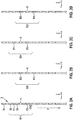
- Fig. 3 shows a diagram to illustrate a traditional high-frequency stimulation waveform between two electrodes E1, E2.
- Stimulation begins with a cathodic phase CP of width W, contains an inter-pulse interval II, and ends with an anodic (charge balancing) phase AP of width W, and repeats.
- the return electrode E2 passes the same but opposite currents. Additional electrodes may share different amounts of current, but with the same timing and wave shape.
- TSE transcutaneous spinal electroanalgesia
- the present invention thus provides an SCS stimulation approach that is designed to reduce energy demand while providing equivalent or improved pain relief and broader therapy coverage of pain dermatomal areas compared to existing methods.
- the present invention can be used with implantable spinal cord stimulators comprising percutaneous electrode or paddle leads implanted in the supra-dural space in the patient's vertebral lumen.
- the present invention particularly allows to provide SCS to patients by allowing the influence of a single pulse on neuron transmembrane potential to maximally take effect prior to charge balancing (polarity reversal) of the stimulating electrode contact by applying a time delay prior to charge balancing.
- the disclosed stimulation maximizes therapeutic effect of stimulating pulses by delivering pulses of the same polarity on adjacent electrode contacts during this delay time.
- this approach departs from traditional neuromodulation stimulation, wherein each stimulation pulse and its charge balancing phase occur prior to stimulation on another set of electrodes.
- Fig. 1 shows in conjunction with Figs. 2 and 4 an embodiment of a medical device 1 according to the present invention, comprising a pulse generator 2 configured to generate current pulses for electrical stimulation of the patient, an electrode lead 3 configured to be connected to the pulse generator 2 and comprising a plurality of electrode contacts E1...E8 for delivering said current pulses to tissue of the patient P, here the spinal cord S, wherein the pulse generator 2 is configured to repeatedly deliver a current pulse CP between two electrodes E1, E3 forming a first group G1 of electrode contacts of said plurality of electrode contacts, and wherein the pulse generator 2 is further configured to deliver a charge balancing current pulse AP after each current pulse CP between said electrodes of the first group such that the respective current pulse CP is separated from the succeeding charge balancing current pulse AP by an inter pulse interval II, wherein the respective current pulse CP comprises an amplitude A that has the same absolute magnitude A than the succeeding charge balancing current pulse AP but is of opposite sign, and wherein the pulse generator 2 is configured
- the pulse generator 2 is further configured to deliver a charge balancing current pulse AP between said electrodes E2, E4 of the second group G2 after each current pulse CP delivered between said electrodes E2, E4 of the second group G2, wherein the respective current pulse CP delivered between said electrodes E2, E4 of the second group G2 comprises an amplitude B that has the same absolute magnitude than the succeeding charge balancing current pulse AP delivered between said electrodes E2, E4 of the second group but is of opposite polarity.
- active electrode contacts E1 to E4 are used according to Fig. 2 that are particularly separated by 7 mm (center-to-center), wherein a corresponding gap between each two neighboring electrodes contacts is filled with an electrical insulating portion 30 forming part of an outer surface 3a of the lead 3.
- said groups G1, G2 of electrode contacts E1....E4 comprise a first, a second, a third, and a fourth electrode contact E1, E2, E3, E4 arranged one after the other in a longitudinal extension direction x of the electrode lead 3, wherein the first group G1 of electrode contacts comprises the first and the third electrode contact E1, E3, and wherein the second group G2 of electrode contacts comprises the second and the fourth electrode contact E2, E4 such that the two groups G1, G2 overlap, i.e.
- the second electrode contact E2 of the second group G2 is arranged between the first and the third electrode contact E1, E3 of the first group G1, and the third electrode contact E3 of the first group G1 is arranged between the second and the fourth electrode contact E2, E4 of the second group G2.
- these electrode contact groups G1, G2 can be used for delivering stimulation from the pulse generator 2 as follows.
- the two groups G1, G2 form two independent stimulation channels, wherein the first provides stimulation through electrode contacts E1 and E3 and the second through electrode contacts E2 and E4.
- Each channel G1, G2 provides bipolar constant current stimulation with a symmetric charge balanced waveform.
- the cathodic stimulation phase (current pulse) CP is balanced by an anodic phase (charge balancing current pulse) AP that is delayed by half a cycle, which also serves as cathodic stimulation on the paired electrode contact.
- the two channels or groups G1, G2 provide stimulation at the same frequency but with a period delay of 0.25 of the cycle time period. This results in cathodic stimulation every 0.25 cycles at an anatomically distinct location, thus providing efficient coverage of therapy.
- the pulse generator 2 is configured to deliver said cathodic current pulses CP in a sequential fashion, i.e. as a sequential cathode train T, such that each electrode contact E1...E4 of the two groups G1, G2 delivers a cathodic current pulse CP following a cathodic current pulse CP of the previous electrode contact and before an anodic charge balancing current pulse AP of the previous electrode contact.
- the respective electrode contact spacing CS as shown in Fig. 2 (e.g. G1), which is defined as 2-20 mm, e.g. 2-3 mm, 7 mm, ,14 mm, is selected large enough to provide effective electric field penetration within and along the spinal cord for complete therapy coverage while minimizing spatial summation of neuron transmembrane potential changes between contacts, inter-pulse intervals are selected large enough to reduce neural refractory effects, and interleaved stimulation are set with symmetric charge balancing phases.
- the stimulation is sub-threshold, i.e. the stimulation amplitude is set under the perception threshold and therefore does not produce sensations that the patient can feel.
- the stimulation begins with a cathodic phase CP, contains an Inter-pulse interval II, and ends with an anodic (charge balancing) phase AP, and repeats.
- the return electrode passes the same but opposite currents.
- the stimulation of the respective group G1 or G2 takes place in between the charge balancing phase of the preceding group G2 or G1.
- the method comprises at least the steps of
- the electrical stimulation preferably results in a sequential cathode train T shown in Fig. 4 , wherein adjacent electrode contacts E1, E2, E3, E4 deliver cathodic stimulation CP following cathodic stimulation of a previous adjacent cathode and before the previous cathode delivers its anodic charge-balancing phase AP.
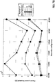
- the simulations were all run using a mathematical axon model coupled to a 3D model of the spinal cord with one single implanted lead positioned against the dura mater on the spinal cord dorso-ventral midline (see Fig. 6 ).
- the activation threshold was calculated for a grid of neurons that covers the dorsal columns area, namely the dorsal column fibers.
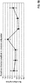
- the amplitude and electrical power required to activate the first 1, 10, 100 and 200 neurons in the superficial dorsal column area are plotted in Figure 7 (A) and (B) , respectively.
- spaced electrode configuration is to be understood as at least two spatially separated electrodes.
- the distance between the electrodes can be e.g. 2-3 mm, 7mm, 14mm (measured center to center of the electrodes).
- the present invention can be used to provide a novel SCS therapeutic stimulation approach which delivers pain relieving neuromodulation at high frequencies and with lower energy requirements and broader coverage compared to the current state-of-the-art.
- This stimulation pattern provides a broader coverage of spinal cord segment levels (along the spinal cord axis) with cathodic stimulation, which is known to drive neuron depolarization. Because of the topographical distribution of fibers in the spinal cord, stimulating a larger longitudinal portion of the spinal cord implies that the activity of neural elements directly or indirectly connected to more dermatomes will be modulated by the stimulation. Moreover, because of the delayed onset time associated with sub-perception SCS and the possible discrepancy in neural target between sub-perception and paresthesia-based SCS therapies, the lead placement is usually not mapped with respect to low-frequency SCS-induced paresthesia, but is rather arbitrary placed at the T9-T10 vertebral junction. By covering a wider portion of the spinal cord levels, this new SCS therapy will be less sensitive to the variations in the analgesic sweet spot.
- the range of possible pulse widths W is larger than in high-frequency stimulation modes.
- programming different pulse widths W will allow for a therapy that is more adaptable to the inter- and intra-patient variability and will therefore increase the rate of SCS responders in the short term, but also the long-term by adapting the stimulation settings to newly developed pain areas.
Applications Claiming Priority (2)
| Application Number | Priority Date | Filing Date | Title |
|---|---|---|---|
| US201862730574P | 2018-09-13 | 2018-09-13 | |
| US201862741573P | 2018-10-05 | 2018-10-05 |
Publications (1)
| Publication Number | Publication Date |
|---|---|
| EP3623004A1 true EP3623004A1 (fr) | 2020-03-18 |
Family
ID=64477004
Family Applications (2)
| Application Number | Title | Priority Date | Filing Date |
|---|---|---|---|
| EP18208288.3A Pending EP3623004A1 (fr) | 2018-09-13 | 2018-11-26 | Thérapie par neuromodulation multi-contact entrelacée à énergie réduite |
| EP20194008.7A Pending EP3791923A1 (fr) | 2018-09-13 | 2020-09-02 | Thérapie par neuromodulation multi-contact entrelacée à énergie réduite |
Family Applications After (1)
| Application Number | Title | Priority Date | Filing Date |
|---|---|---|---|
| EP20194008.7A Pending EP3791923A1 (fr) | 2018-09-13 | 2020-09-02 | Thérapie par neuromodulation multi-contact entrelacée à énergie réduite |
Country Status (4)
| Country | Link |
|---|---|
| US (2) | US11135427B2 (fr) |
| EP (2) | EP3623004A1 (fr) |
| JP (2) | JP2020039868A (fr) |
| CN (2) | CN110893261B (fr) |
Cited By (3)
| Publication number | Priority date | Publication date | Assignee | Title |
|---|---|---|---|---|
| WO2022076913A1 (fr) * | 2020-10-08 | 2022-04-14 | Medtronic, Inc. | Stimulation multimodale à faible énergie |
| WO2022183201A1 (fr) * | 2021-02-24 | 2022-09-01 | Medtronic, Inc. | Neurostimulation utilisant une cascade entrelacée dans le temps de combinaisons d'électrodes bipolaires |
| WO2023126842A1 (fr) * | 2021-12-29 | 2023-07-06 | Novocure Gmbh | Appareil destiné à réduire l'électrosensibilité par recours à des champs électriques alternatifs générés à l'aide de cathodes plus grandes et d'anodes plus petites |
Families Citing this family (12)
| Publication number | Priority date | Publication date | Assignee | Title |
|---|---|---|---|---|
| US8255057B2 (en) | 2009-01-29 | 2012-08-28 | Nevro Corporation | Systems and methods for producing asynchronous neural responses to treat pain and/or other patient conditions |
| DE202010018338U1 (de) | 2009-04-22 | 2015-10-12 | Nevro Corporation | Rückenmarksmodulationsystem zur Linderung chronischer Schmerzen |
| EP2756864B1 (fr) | 2009-04-22 | 2023-03-15 | Nevro Corporation | Systèmes de modulation de la moelle épinière pour induire des effets paresthésiques |
| WO2013036880A1 (fr) | 2011-09-08 | 2013-03-14 | Thacker James R | Modulation sélective à haute fréquence de la moelle épinière pour atténuer la douleur, y compris les douleur céphaliques et / ou du corps entier, avec effets secondaires réduits, et systèmes et procédés associés |
| AU2015264561B2 (en) | 2014-05-20 | 2020-02-20 | Nevro Corporation | Implanted pulse generators with reduced power consumption via signal strength/duration characteristics, and associated systems and methods |
| US10300277B1 (en) | 2015-12-14 | 2019-05-28 | Nevro Corp. | Variable amplitude signals for neurological therapy, and associated systems and methods |
| US11058875B1 (en) | 2018-09-19 | 2021-07-13 | Nevro Corp. | Motor function in spinal cord injury patients via electrical stimulation, and associated systems and methods |
| US11590352B2 (en) | 2019-01-29 | 2023-02-28 | Nevro Corp. | Ramped therapeutic signals for modulating inhibitory interneurons, and associated systems and methods |
| AU2021211011A1 (en) | 2020-01-25 | 2022-08-11 | Nevro Corp. | Systems and methods for direct suppression of nerve cells |
| WO2021263007A1 (fr) * | 2020-06-24 | 2021-12-30 | Medtronic, Inc. | Forme d'onde biphasique divisée pour réduction embolique |
| EP4313260A1 (fr) * | 2021-03-31 | 2024-02-07 | BIOTRONIK SE & Co. KG | Thérapie de stimulation multi-électrodes de moelle épinière |
| CN116271516B (zh) * | 2023-03-29 | 2023-11-14 | 中国人民解放军军事科学院军事医学研究院 | 一种脊髓硬膜外植入多模式贴片电极 |
Citations (4)
| Publication number | Priority date | Publication date | Assignee | Title |
|---|---|---|---|---|
| US20130261706A1 (en) * | 2012-03-30 | 2013-10-03 | Neuropace, Inc. | Systems and methods for applying rapid sequential electrode stimulation |
| US20140243924A1 (en) * | 2013-02-22 | 2014-08-28 | Boston Scientific Neuromodulation Corporation | Neurostimulation system having increased flexibility for creating complex pulse trains |
| US20170001014A1 (en) | 2009-12-30 | 2017-01-05 | Boston Scientific Neuromodulation Corporation | System and method for independently operating multiple neurostimulation channels |
| WO2018187734A1 (fr) * | 2017-04-07 | 2018-10-11 | Medtronic, Inc. | Variation complexe de paramètres en thérapie par stimulation électrique |
Family Cites Families (13)
| Publication number | Priority date | Publication date | Assignee | Title |
|---|---|---|---|---|
| WO2004012813A1 (fr) * | 2002-07-31 | 2004-02-12 | Advanced Neuromodulation Systems, Inc. | Generateur d'impulsions haute frequence pour neurostimulateur implantable |
| US8180445B1 (en) * | 2007-03-30 | 2012-05-15 | Boston Scientific Neuromodulation Corporation | Use of interphase to incrementally adjust the volume of activated tissue |
| GB0709834D0 (en) * | 2007-05-22 | 2007-07-04 | Gillbe Ivor S | Array stimulator |
| US8352026B2 (en) * | 2007-10-03 | 2013-01-08 | Ethicon, Inc. | Implantable pulse generators and methods for selective nerve stimulation |
| US8862237B2 (en) * | 2010-06-14 | 2014-10-14 | Boston Scientific Neuromodulation Corporation | Programming interface for spinal cord neuromodulation |
| WO2013036880A1 (fr) | 2011-09-08 | 2013-03-14 | Thacker James R | Modulation sélective à haute fréquence de la moelle épinière pour atténuer la douleur, y compris les douleur céphaliques et / ou du corps entier, avec effets secondaires réduits, et systèmes et procédés associés |
| US9044610B2 (en) * | 2013-03-15 | 2015-06-02 | Pacesetter, Inc. | Systems and methods for providing a distributed virtual stimulation cathode for use with an implantable neurostimulation system |
| US20150119954A2 (en) * | 2013-05-24 | 2015-04-30 | Case Western Reserve University | Systems and methods that provide electrical stimulation to a nerve to reduce a reflex that affect a bodily function |
| WO2015100306A1 (fr) * | 2013-12-23 | 2015-07-02 | Deep Brain Innovations LLC | Systemes de programmation pour systeme de stimulation cerebrale profonde |
| CN117482396A (zh) * | 2014-08-26 | 2024-02-02 | 阿文特投资有限责任公司 | 选择性神经纤维阻断方法和系统 |
| US10525268B2 (en) | 2016-08-23 | 2020-01-07 | Medtronic, Inc. | Delivery of independent interleaved programs to produce higher-frequency electrical stimulation therapy |
| WO2018140864A1 (fr) * | 2017-01-30 | 2018-08-02 | Boston Scientific Neuromodulation Corporation | Étalonnage de sous-perception à l'aide d'une mise à l'échelle de domaine temporel |
| US20190175904A1 (en) | 2017-12-13 | 2019-06-13 | BIOTRONIK SE &. Co. KG | Spinal cord stimulation |
-
2018
- 2018-11-26 EP EP18208288.3A patent/EP3623004A1/fr active Pending
-
2019
- 2019-08-20 JP JP2019150232A patent/JP2020039868A/ja not_active Ceased
- 2019-09-09 CN CN201910865023.1A patent/CN110893261B/zh active Active
- 2019-09-12 US US16/569,160 patent/US11135427B2/en active Active
- 2019-10-17 US US16/656,120 patent/US11235153B2/en active Active
-
2020
- 2020-09-02 EP EP20194008.7A patent/EP3791923A1/fr active Pending
- 2020-09-11 JP JP2020152799A patent/JP2021041170A/ja active Pending
- 2020-09-14 CN CN202010959581.7A patent/CN112473001A/zh active Pending
Patent Citations (4)
| Publication number | Priority date | Publication date | Assignee | Title |
|---|---|---|---|---|
| US20170001014A1 (en) | 2009-12-30 | 2017-01-05 | Boston Scientific Neuromodulation Corporation | System and method for independently operating multiple neurostimulation channels |
| US20130261706A1 (en) * | 2012-03-30 | 2013-10-03 | Neuropace, Inc. | Systems and methods for applying rapid sequential electrode stimulation |
| US20140243924A1 (en) * | 2013-02-22 | 2014-08-28 | Boston Scientific Neuromodulation Corporation | Neurostimulation system having increased flexibility for creating complex pulse trains |
| WO2018187734A1 (fr) * | 2017-04-07 | 2018-10-11 | Medtronic, Inc. | Variation complexe de paramètres en thérapie par stimulation électrique |
Cited By (3)
| Publication number | Priority date | Publication date | Assignee | Title |
|---|---|---|---|---|
| WO2022076913A1 (fr) * | 2020-10-08 | 2022-04-14 | Medtronic, Inc. | Stimulation multimodale à faible énergie |
| WO2022183201A1 (fr) * | 2021-02-24 | 2022-09-01 | Medtronic, Inc. | Neurostimulation utilisant une cascade entrelacée dans le temps de combinaisons d'électrodes bipolaires |
| WO2023126842A1 (fr) * | 2021-12-29 | 2023-07-06 | Novocure Gmbh | Appareil destiné à réduire l'électrosensibilité par recours à des champs électriques alternatifs générés à l'aide de cathodes plus grandes et d'anodes plus petites |
Also Published As
| Publication number | Publication date |
|---|---|
| JP2021041170A (ja) | 2021-03-18 |
| US20200086123A1 (en) | 2020-03-19 |
| US11135427B2 (en) | 2021-10-05 |
| JP2020039868A (ja) | 2020-03-19 |
| CN110893261B (zh) | 2024-04-16 |
| EP3791923A1 (fr) | 2021-03-17 |
| CN112473001A (zh) | 2021-03-12 |
| US20200086124A1 (en) | 2020-03-19 |
| CN110893261A (zh) | 2020-03-20 |
| US11235153B2 (en) | 2022-02-01 |
Similar Documents
| Publication | Publication Date | Title |
|---|---|---|
| EP3791923A1 (fr) | Thérapie par neuromodulation multi-contact entrelacée à énergie réduite | |
| US11745007B2 (en) | Multi-electrode stimulation therapy with reduced energy | |
| US9254386B2 (en) | System and method for modulating action potential propagation during spinal cord stimulation | |
| US9604058B2 (en) | Method for achieving low-back spinal cord stimulation without significant side-effects | |
| US8923988B2 (en) | Method for epidural stimulation of neural structures | |
| US9393423B2 (en) | Fractionalized stimulation pulses in an implantable stimulator device | |
| EP3528890B1 (fr) | Système de neuromodulation pour générer des champs à phases multiples | |
| JP2017505195A (ja) | 変調閾値以下治療を患者に行うシステム及び方法 | |
| US20170281949A1 (en) | Distributed electrode lead configurations and associated systems and methods | |
| US20200147390A1 (en) | Spinal Cord Stimulation for Dorsal Column Recruitment or Suppression Using Anodic and Cathodic Pulses | |
| US8706240B2 (en) | Method for direct modulation of the spinothalamic tract | |
| WO2020227390A1 (fr) | Procédé et appareil de modulation électrique multiplexée ou multimodale de la douleur à l'aide de champs électromagnétiques composites | |
| US8923974B2 (en) | System and method for electrical modulation of the posterior Longitudinal ligament | |
| AU2020220021B2 (en) | Spinal cord stimulation for dorsal column recruitment or suppression using anodic and cathodic pulses | |
| US20230121243A1 (en) | Stimulation Targeting and Calibration for Enhanced Surround Inhibition Recruitment in Spinal Cord Stimulation Therapy | |
| WO2022207269A1 (fr) | Thérapie de stimulation multi-électrodes de moelle épinière |
Legal Events
| Date | Code | Title | Description |
|---|---|---|---|
| PUAI | Public reference made under article 153(3) epc to a published international application that has entered the european phase |
Free format text: ORIGINAL CODE: 0009012 |
|
| STAA | Information on the status of an ep patent application or granted ep patent |
Free format text: STATUS: THE APPLICATION HAS BEEN PUBLISHED |
|
| AK | Designated contracting states |
Kind code of ref document: A1 Designated state(s): AL AT BE BG CH CY CZ DE DK EE ES FI FR GB GR HR HU IE IS IT LI LT LU LV MC MK MT NL NO PL PT RO RS SE SI SK SM TR |
|
| AX | Request for extension of the european patent |
Extension state: BA ME |
|
| STAA | Information on the status of an ep patent application or granted ep patent |
Free format text: STATUS: REQUEST FOR EXAMINATION WAS MADE |
|
| 17P | Request for examination filed |
Effective date: 20200915 |
|
| RBV | Designated contracting states (corrected) |
Designated state(s): AL AT BE BG CH CY CZ DE DK EE ES FI FR GB GR HR HU IE IS IT LI LT LU LV MC MK MT NL NO PL PT RO RS SE SI SK SM TR |
|
| STAA | Information on the status of an ep patent application or granted ep patent |
Free format text: STATUS: EXAMINATION IS IN PROGRESS |
|
| STAA | Information on the status of an ep patent application or granted ep patent |
Free format text: STATUS: EXAMINATION IS IN PROGRESS |
|
| 17Q | First examination report despatched |
Effective date: 20211126 |