EP3622121B1 - In-situ barrier device with internal injection conduit - Google Patents
In-situ barrier device with internal injection conduit Download PDFInfo
- Publication number
- EP3622121B1 EP3622121B1 EP18727603.5A EP18727603A EP3622121B1 EP 3622121 B1 EP3622121 B1 EP 3622121B1 EP 18727603 A EP18727603 A EP 18727603A EP 3622121 B1 EP3622121 B1 EP 3622121B1
- Authority
- EP
- European Patent Office
- Prior art keywords
- layer
- injection
- open
- fluid
- conduit member
- Prior art date
- Legal status (The legal status is an assumption and is not a legal conclusion. Google has not performed a legal analysis and makes no representation as to the accuracy of the status listed.)
- Active
Links
Images


Classifications
-
- E—FIXED CONSTRUCTIONS
- E02—HYDRAULIC ENGINEERING; FOUNDATIONS; SOIL SHIFTING
- E02D—FOUNDATIONS; EXCAVATIONS; EMBANKMENTS; UNDERGROUND OR UNDERWATER STRUCTURES
- E02D31/00—Protective arrangements for foundations or foundation structures; Ground foundation measures for protecting the soil or the subsoil water, e.g. preventing or counteracting oil pollution
- E02D31/02—Protective arrangements for foundations or foundation structures; Ground foundation measures for protecting the soil or the subsoil water, e.g. preventing or counteracting oil pollution against ground humidity or ground water
- E02D31/04—Watertight packings for use under hydraulic pressure
-
- E—FIXED CONSTRUCTIONS
- E21—EARTH DRILLING; MINING
- E21D—SHAFTS; TUNNELS; GALLERIES; LARGE UNDERGROUND CHAMBERS
- E21D11/00—Lining tunnels, galleries or other underground cavities, e.g. large underground chambers; Linings therefor; Making such linings in situ, e.g. by assembling
- E21D11/38—Waterproofing; Heat insulating; Soundproofing; Electric insulating
- E21D11/381—Setting apparatus or devices
-
- E—FIXED CONSTRUCTIONS
- E02—HYDRAULIC ENGINEERING; FOUNDATIONS; SOIL SHIFTING
- E02D—FOUNDATIONS; EXCAVATIONS; EMBANKMENTS; UNDERGROUND OR UNDERWATER STRUCTURES
- E02D19/00—Keeping dry foundation sites or other areas in the ground
- E02D19/06—Restraining of underground water
- E02D19/12—Restraining of underground water by damming or interrupting the passage of underground water
- E02D19/18—Restraining of underground water by damming or interrupting the passage of underground water by making use of sealing aprons, e.g. diaphragms made from bituminous or clay material
-
- E—FIXED CONSTRUCTIONS
- E02—HYDRAULIC ENGINEERING; FOUNDATIONS; SOIL SHIFTING
- E02D—FOUNDATIONS; EXCAVATIONS; EMBANKMENTS; UNDERGROUND OR UNDERWATER STRUCTURES
- E02D31/00—Protective arrangements for foundations or foundation structures; Ground foundation measures for protecting the soil or the subsoil water, e.g. preventing or counteracting oil pollution
- E02D31/02—Protective arrangements for foundations or foundation structures; Ground foundation measures for protecting the soil or the subsoil water, e.g. preventing or counteracting oil pollution against ground humidity or ground water
-
- E—FIXED CONSTRUCTIONS
- E21—EARTH DRILLING; MINING
- E21D—SHAFTS; TUNNELS; GALLERIES; LARGE UNDERGROUND CHAMBERS
- E21D11/00—Lining tunnels, galleries or other underground cavities, e.g. large underground chambers; Linings therefor; Making such linings in situ, e.g. by assembling
- E21D11/38—Waterproofing; Heat insulating; Soundproofing; Electric insulating
- E21D11/383—Waterproofing; Heat insulating; Soundproofing; Electric insulating by applying waterproof flexible sheets; Means for fixing the sheets to the tunnel or cavity wall
-
- E—FIXED CONSTRUCTIONS
- E02—HYDRAULIC ENGINEERING; FOUNDATIONS; SOIL SHIFTING
- E02D—FOUNDATIONS; EXCAVATIONS; EMBANKMENTS; UNDERGROUND OR UNDERWATER STRUCTURES
- E02D2250/00—Production methods
- E02D2250/003—Injection of material
-
- E—FIXED CONSTRUCTIONS
- E02—HYDRAULIC ENGINEERING; FOUNDATIONS; SOIL SHIFTING
- E02D—FOUNDATIONS; EXCAVATIONS; EMBANKMENTS; UNDERGROUND OR UNDERWATER STRUCTURES
- E02D2300/00—Materials
- E02D2300/0004—Synthetics
- E02D2300/0018—Cement used as binder
- E02D2300/002—Concrete
-
- E—FIXED CONSTRUCTIONS
- E02—HYDRAULIC ENGINEERING; FOUNDATIONS; SOIL SHIFTING
- E02D—FOUNDATIONS; EXCAVATIONS; EMBANKMENTS; UNDERGROUND OR UNDERWATER STRUCTURES
- E02D2300/00—Materials
- E02D2300/0004—Synthetics
- E02D2300/0025—Adhesives, i.e. glues
-
- E—FIXED CONSTRUCTIONS
- E02—HYDRAULIC ENGINEERING; FOUNDATIONS; SOIL SHIFTING
- E02D—FOUNDATIONS; EXCAVATIONS; EMBANKMENTS; UNDERGROUND OR UNDERWATER STRUCTURES
- E02D2300/00—Materials
- E02D2300/0075—Textiles
- E02D2300/0076—Textiles non-woven
-
- E—FIXED CONSTRUCTIONS
- E02—HYDRAULIC ENGINEERING; FOUNDATIONS; SOIL SHIFTING
- E02D—FOUNDATIONS; EXCAVATIONS; EMBANKMENTS; UNDERGROUND OR UNDERWATER STRUCTURES
- E02D2300/00—Materials
- E02D2300/0075—Textiles
- E02D2300/0078—Textiles woven
Definitions
- the invention relates to a barrier device for post-installation injection of a waterproofing fluid; and, more particularly, to a multi-layer device having first and second layers defining an intermediate open-matrix layer, and at least one injection conduit member disposed in parallel orientation with respect to the first and second layers to permit a waterproofing fluid to be injected into the open-matrix layer.
- the at least one injection conduit member may be located between the first and second layers and thus within the open matrix layer, at the edge of the multi-layer device and adjacent to an open matrix layer, along an outer face of the first layer if the first layer is made of nonwoven or woven fabric, or combination of these locations, whereby an injection fluid can be conveyed through the conduit member and into the open matrix layer.
- the use of multi-layer devices for post-installation, in-situ creation of barriers for waterproofing of concrete constructions is known.
- An applicator places such devices against a substrate, such as formwork or existing wall, and applies concrete against the devices. Thereafter, an applicator can inject a waterproofing fluid into the devices.
- the waterproofing fluid may comprise waterproofing resins or cements, insecticides, mold preventatives, rust retardants, and the like, for creating a watertight barrier, or so-called "grout wall,” to protect the concrete structure.
- the injection of the fluid allows for remedial waterproofing treatment after installation of the device and after spraying or casting concrete against the device.
- the grout wall devices can be attached to the exterior of a shoring system, a tunnel excavation wall, a concrete formwork, or other substrates or structures.
- Characteristic of the Iske devices were a plurality of injection tubes that jutted perpendicularly out of the outermost layer of the multi-layered devices.
- the orientation and placement of these perpendicularly, outward-extending tubes enabled injection of the waterproofing fluid (e.g., grouts, resins, etc.) into the device after concrete was applied against the exterior of the installed multi-layer device.
- the waterproofing fluid e.g., grouts, resins, etc.
- the tubes or pipes extended perpendicularly through the outermost layer of the devices and through the placed concrete structure and required placement to ensure that the injection fluid would be able to fill completely the multi-layer device behind the concrete ( See e.g., US Patent 7,836,650 at Figs. 5-6 ).
- JP2004060217A discloses a waterproof sheet with injection pipe, in which the injection pipe injects the filler for filling the cavity part generated between the waterproof sheet and placing concrete, and is attached to one surface of the waterproof sheet used for the concrete underground structure such as the tunnel.
- the present invention provides a multi-layer device that enables faster and more convenient installation of a grout wall system, and particularly for establishing a grout wall using an assembly of such multi-layer devices.
- An exemplary device of the invention for post-installation in-situ barrier creation comprises a multi-layer fluid delivery device and at least one injection conduit member, wherein: the multi-layer fluid delivery device comprises first and second layers defining an intermediate open-matrix layer for an injection fluid; the first layer has an inwardly facing surface and an outwardly facing surface, the first layer being permeable to the injection fluid but at least nearly impermeable to a structural construction material to be applied against the outwardly facing surface of the first layer, and the second layer is water-impermeable and has an inwardly facing first side and an outwardly facing second side, the inwardly facing first side of the second layer being affixed, directly or indirectly to the inwardly facing surface of the first layer such that all or a substantial portion of the second layer is spaced apart from the first layer, using an open-matrix structure to create air space between the first layer and the second layer and thereby defining the open-matrix layer for conducting the injection fluid between said first and second layers; the at least one injection conduit
- the injection fluid may be chosen from waterproofing resin, grout, cement, insecticide, mold preventative, rust retardant, and mixtures thereof.
- the first layer is permeable to the injection fluid and nearly impermeable to the structural construction material (e.g., concrete), and comprises a non-woven or woven fabric; while the second layer is water-impermeable, and comprises a polymer film (e.g., polyethylene, polypropylene).
- the structural construction material e.g., concrete
- the second layer is water-impermeable, and comprises a polymer film (e.g., polyethylene, polypropylene).
- the multi-layer device can be assembled from separate components at the construction site, the inventors believe that it is more convenient, efficient, and faster to use pre-assembled multi-layer devices, so that installation effort and time are minimized. In either case, one creates an "in situ" (or "in place") barrier system that defines a confined flow area for injection fluids such as waterproofing resins and grouts.
- the present invention has particular value in vertical wall applications, especially for sealing to prevent leakages at cold joints, as defined between concrete floors and subsequently poured vertical walls.
- the device is assembled or installed as a pre-assembled unit against a substrate (e.g., excavation, existing wall or foundation, formwork or mold, tunnel wall, etc.), and, subsequently, concrete is cast or sprayed against its outward-facing layer.
- the device may also be assembled or installed in horizontal applications, such as sub-layer or subflooring for concrete slabs, decks, and floor applications, including applications where the existence and location of joints and segment dimensions are not predictable or uniform.
- the devices and assemblies of the invention can protect against moisture penetration due to crack formations or other leakage pathways formed within or between concrete structures.
- the outward face layer of the multi-layer device is preferably porous, such as in a nonwoven or woven fabric, which allows the injection fluid to fill in the open-matrix intermediate layer and flows through the outward face porous layer to fill in voids or discontinuities in the construction material (e.g., concrete) that is cast or sprayed against the multi-layer device.
- the construction material e.g., concrete
- the present invention also has particular value in shotcrete applications, wherein concrete is sprayed against the outward face of the device.
- shotcrete applications wherein concrete is sprayed against the outward face of the device.
- the device of the invention When the device of the invention is installed against a wall, and concrete is poured or spray-applied against rebar adjacent the installed device, the device will allow a subsequently injected resin or grout to permeate through the outward face porous layer and fill in "shadow" areas where the rebar interrupts the path of the poured or sprayed concrete (or shotcrete), thereby creating a full contact seal with the concrete (or shotcrete).
- the barrier devices of the present invention having the at least one injection conduit member in parallel orientation with respect to the first and second layers are provided in rollable or stacked form that can be used conveniently and quickly at the construction site.
- two or more pre-assembled multi-layer fluid delivery units can be connected together to form a monolithic barrier layer wherein their at least one injection conduit member(s) are connected to permit an injection fluid (e.g., grout, resin, cement) to be pumped through and/or into several barrier devices at once, thereby creating a monolithic water-resistive curtain over an area that is larger than an individual barrier device.
- an injection fluid e.g., grout, resin, cement
- the concrete which is subsequently cast or sprayed against the installed barrier devices allow the in-situ barriers to stay in place during fluid injection, and to resist the compressive pressure required to inject the fluid into the open-matrix intermediate layer and through the permeable outward porous (e.g., woven or nonwoven) fabric which comprises the outward face layer.
- permeable outward porous (e.g., woven or nonwoven) fabric which comprises the outward face layer.
- the layer installed against a formwork or other substrate comprises a water-impermeable polymer film (e.g., polyolefin), and the layer disposed outwards for bonding with cast or sprayed concrete comprises a non-woven material (e.g., polypropylene, nylon, polyamide).
- a non-woven material e.g., polypropylene, nylon, polyamide.
- the outward-facing non-woven layer allows for permeation of the injection fluid (e.g., grout, resin, cement) into and out of the intermediate open-matrix layer, while essentially blocking concrete or other construction material cast against the barrier device from entering into the open-matrix intermediate layer.
- the injection fluid e.g., grout, resin, cement
- the present invention also provides a method for creating an in-situ barrier device (or assembly), wherein the above barrier device is attached or assembled against an excavation wall, lagging form, or shoring system, where concrete is thereafter applied (e.g., sprayed, poured) against the outer layer of the barrier device; and an injection fluid is subsequently injected through the at least one injection conduit and into the space defined by the open-matrix intermediate layer.
- Especially preferred devices of the invention comprise one or more injection conduit members disposed in parallel orientation with respect to the first and second layers, and can be (i) located within the open-matrix layer and thus between the first and second layer, (ii) located adjacent the open-matrix layer (along an edge of the device); (iii) located against the outwardly facing surface of the first layer which is permeable to injection fluid; or (iv) located in a combination or all of the foregoing locations (i), (ii), and (iii).
- the present invention avoids the inconvenience of having to install numerous injection tubes extending perpendicularly across the outward face of the device, as well as the inconvenience of applying concrete around the perpendicularly extending tubes.
- a gelation activator is pre-applied within the open-matrix layer defined between the first and second layers (hereinafter "gel activator").
- the gel activator functions as an accelerator, catalyst, hardener, resin and/or curative agent to increase or to initiate gelation (e.g., hardening, stiffening, polymerization) of the injection fluid once it is introduced into the open matrix layer.
- the injection fluid could be a polyol resin
- the gel activator could be an isocyanate functional resin, to generate a polyurethane grout wall composition within the barrier device.
- the injection fluid could be an isocyanate resin
- the gel activator could be an amine resin, to generate a polyurea grout wall within the barrier device.
- An amine gel activator or a free radical gel activator could be used for injection fluids that were based on polyacrylate.
- a still further example involves use of an epoxy resin injection fluid, and an amine resin as gel activator.
- the gel activator for hydratable cementitious injection fluids could be a set accelerator (e.g., calcium nitrite and/or nitrate) to quicken the setting of the cement.
- the injection fluid may comprise a sodium silicate solution and the gel activator may comprise an acid or an alkaline earth salt or an aluminum salt.
- the gel activator is pre-installed or preapplied (e.g. coated, sprayed, brushed) into the open-matrix layer structure, such as into a non-woven geotextile mat used for separating the first and second layers of the barrier device. Consequently, a highly flowable injection fluid can be introduced into the barrier device without the need for high-powered, multi-component pump equipment.
- a simple, single component pump equipment is used. Upon contact with the gel activator located within the open-matrix layer, the injection fluid will begin to gel (e.g., assume higher viscosity) and ensure that a grout wall is established against concrete that was cast against the installed barrier.
- pre-installed gel activator will benefit the use of the herein-described barrier devices having injection conduit members disposed in parallel orientation with respect to the first and second layers.
- the pre-installed gel activator will also benefit conventional grout wall barrier designs (e.g., US Patent 7,565,799 ) which employ tubes extending perpendicularly from the structure.
- another exemplary multi-layer fluid delivery device of the present invention comprises first and second layers defining an intermediate open-matrix layer for an injection fluid; the first layer having an inwardly facing surface and an outwardly facing surface, the first layer being permeable to the injection fluid but at least nearly impermeable to a structural construction material to be applied against the outwardly facing surface of the first layer, and the second layer being water-impermeable and having an inwardly facing first side and an outwardly facing second side, the inwardly facing first side of the second layer being affixed, directly or indirectly to the inwardly facing surface of the first layer such that all or a substantial portion of the second layer is spaced apart from the first layer, using an open-matrix structure to create air space between the first layer and the second layer and thereby defining an open-matrix layer for conducting an injection fluid between said first and second layers; and at least one injection conduit member disposed in parallel orientation with respect to the first layer and second layer, the at least one injection conduit member for conveying an injection fluid into
- a gel activator is pre-installed, wherein gelation is initiated or accelerated in injection fluids introduced through parallel and/or perpendicular injection tubes, or even where injection fluid is introduced without injection tubes but through holes drilled in concrete that was hardened against the installed barrier device.
- the present invention relates to a multi-layer assembly or device for a post-installation in-situ barrier, as well as a method for assembling the barrier, using one or more injection conduit members that are parallel to the major faces or layers of the assembly or device, in contrast to the prior art use of perpendicularly extending pipes as taught by Iske et al. as mentioned in the Background section.
- assembly and “device” may be used interchangeably throughout this specification. Ideally, relatively little assembly of an individual multi-layer device is required at the construction site, although the establishment of a grout wall against concrete that is poured or sprayed against a number of such individual multi-layer devices will require some "assembly" to join individual multi-layer devices together, including injection conduit members to permit filling two or more of the devices using a single source of injection fluid. (This will be described further hereinafter during discussion of Figs. 3A and 3B ).
- two or more multi-layered devices can be joined together, thereby allowing for the creation of a grout wall to seal against subsequently applied concrete, using injection conduit members which can be (i) located within the open-matrix layer and thus between the first and second layers of the multi-layered device, (ii) located adjacent the open-matrix layer at an edge of one or more multi-layered devices; (iii) located against the outwardly facing surface of the first layer(s) which is permeable to injection fluid; or (iv) located in a combination or all of the foregoing locations (i), (ii), and (iii).
- a barrier device can be assembled at a construction site by providing the multi-layer device having a first layer (e.g., a nonwoven which is permeable to a waterproofing grout, resin, cement, or other injection fluid), a second layer (e.g., a water-impermeable polymeric film), and an open-matrix structure for connecting the first and second layers together but defining a space for filling with injection fluid; and an injection conduit (e.g., spiral wrap tubing) can be taped against the first layer (nonwoven) in a manner to allow injection fluid to be pumped through the nonwoven first layer so as to fill the intermediate open-matrix layer and to fill any gaps or discontinuities in concrete which is applied against the outer layer of the device.
- a first layer e.g., a nonwoven which is permeable to a waterproofing grout, resin, cement, or other injection fluid
- a second layer e.g., a water-impermeable polymeric film
- an open-matrix structure for
- the barrier device can be adhered in strip form against a substrate, and an injection conduit member can be placed next to one or both edges along the strip, and taped in place, such that injection fluid can be pumped through and out of the injection conduit member and into the intermediate open matrix layers of the adjacent barrier device or devices.
- the multi-layer barrier device may be pre-assembled having at least one integral injection conduit member between the first and second layers and thus embedded already within the intermediate open-matrix layer. This may facilitate installation, as well as waterproofing performance, because the applicator may also install additional injection conduit members in parallel fashion along an edge and/or outward face of the barrier devices, whereby an injection grout, cement, resin, or other fluid can be introduced from openings along the length of the injection conduit member into spaces within the intermediate open-matrix layers of the barrier devices.
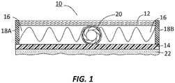
- an exemplary device 10 for post-installation in-situ barrier creation comprises a first layer 12 and second layer 14 which define an intermediate open-matrix layer 16, and at least one injection conduit member 20 that is disposed in parallel orientation with respect to and between the first and second layers 12/14.
- the length of the at least one conduit member 20 is preferably substantially coextensive with a width or length of the device 10.
- the at least one injection conduit member 20 has openings (not shown in this view) for introducing an injection fluid between the first layer 12 and second layer 14 and into the spaces within the open-matrix intermediate layer 16.
- the first layer 12 of the at least two spaced-apart layers is preferably non-permeable or semi-permeable to the injection fluid which is introduced into the intermediate open-matrix layer 16; while the second 14 of the at least two spaced-apart co-extensive layers is preferably a polymer film which is non-permeable to the injection fluid which is introduced into the intermediate open-matrix layer 16.
- the first layer 12 can be a non-woven synthetic fabric of the kind used for bonding with fresh concrete cast or sprayed against it and allowed to cure into a hardened state.
- a pressure-sensitive adhesive layer 22 may be attached to the second layer 14 to facilitate installation of the device or assembly 10 against a substrate, such as an excavation wall, a concrete wall or foundation, a formwork, a scaffolding structure, or other mounting surface.
- Fig. 1 also illustrates the exemplary use of optional containment members (designated at 18A and 18B) for enclosing the space defined by the open-matrix layer 16 that is intermediate between the first layer 12 and second layer 14.
- the containment layers 18A/18B may comprise, for example, an adhesive tape for sealing the edges and thereby joining the first layer 12 and second layer 14.
- the containment members 18A and 18B may be provided or formed by folding extending sides of a wider or longer second layer 14 (particularly if the second layer is an impermeable film) around the edge of the intermediate open-matrix layer 16 and attaching the extended sides (18A/18B) onto the first layer 12 of the barrier device 10, either at or before installation.
- the first layer 12 is preferably made from a synthetic felt or other non-woven fiber material, which is permeable to the injection grout, resin, cement or other fluid, but partly impermeable to fresh concrete that is cast against it.
- a synthetic felt or other non-woven fiber material which is permeable to the injection grout, resin, cement or other fluid, but partly impermeable to fresh concrete that is cast against it.
- partially impermeable it is intended that the fresh concrete is able to flow into interstices between the fibers of the felt or non-woven fiber material and to create a bond with the concrete when the concrete becomes hardened; and it is preferable to select the felt or non-woven fiber material such that the concrete does not entirely penetrate into the intermediate open-matrix layer 16 thereby to prevent the grout, resin, or other injection fluid from being able to fill up the spaces defined by the open matrix layer 16 within the barrier device 10, or to block the injection fluid from permeating the nonwoven, felt, or other fiber material which constitutes the first layer 12 and from filling gaps or discontinuities between the
- Various exemplary structures 16 can be used for spacing apart the first and second layers 12/14 and defining the space within the intermediate open-matrix layer 16.
- Iske et al. taught the use of frusto-conical shaped structures in addition to other protuberances, wave-shaped ribs, and geotextile non-woven layers.
- Iske et al. taught the use of frusto-conical shaped structures in addition to other protuberances, wave-shaped ribs, and geotextile non-woven layers.
- the present inventors consider these various brands of geotextile products to be suitable for use in the present invention, and their selection would be subject to the preference of the device designer, assuming compatability with the size of internal injection fluid conduit tubing 20 used between the first and second layers 12/14 of the barrier device 10.
- the present inventors contemplate the use of a three-dimensional membrane with open cell structure formed by continuous extrusion of two intersecting high density polyethylene (HDPE) strands to form a high profile, biaxial netlike mesh.
- the polymer strands may intersect randomly, and the form the shape of evenly spaced ribs or undulations, for spacing apart the first layer 12 and second layer 14, and permitting air channels having high capacity for the injection of chemical fluids such as grouts, resins, and cements which are typically used in waterproofing.
- the preferred thickness of this exemplary open-matrix layer is about 3.18 mm to 9.53 mm (1/8 inches to 3/8 inches).
- the density of the open-matrix layer may, for example, be in the range of 215 gm/m 2 to 861 gm/m 2 (20 gm/ft 2 to 80 gm/ft 2 ), more preferably between 323 gm/m 2 to 753 gm/m 2 (30 gm/ft 2 to 70 gm/ft 2 ), and most preferably between 484 gm/m 2 to 646 gm/m 2 (45 gm/ft 2 to 60 gm/ft 2 ).
- the second layer 14 is preferably a water-impermeable polymer film (e.g., polyolefin). More preferably, both first layer 12 and second layer 14 will each have linear edges along their respective width and length dimensions. If an injection conduit member 20 is positioned parallel to one of the width or length linear edges of the device 10, it may comprise a plurality of openings to permit an injection fluid to be introduced into the intermediate open-matrix layer 16 of a given device 10, or have separate holes or "T" or "X" joints to permit fluid communication/connection to injection conduit members that are located within the devices 10.
- a water-impermeable polymer film e.g., polyolefin
- an exemplary multi-layer fluid delivery device 10 of the invention comprises at least one injection conduit member 20 positioned between the at least two spaced-apart first and second layers 12 and 14 (where only the first layer 12 is illustrated).
- the one or more injection conduit member(s) is/are contained integrally within the intermediate open-matrix layer 16 and preferably shipped as a pre-assembled unit.
- the injection conduit member 20 may comprise a flexible plastic (e.g., nylon) tubing having openings 21, such as slits, which move resiliently into an opened position when injection fluid which is pumped into an end of the piping 24 to permit the injection fluid (26) to exit into the open-matrix layer (16).
- the slit openings 21 should return to a closed position when the injection fluid is no longer subject to pressure.
- the injection conduit member 20 can be formed by spiral wrapping of a ribbon shaped polymer to form a tubing; whereby openings to allow exit of the injection fluid are defined by spaces between the spiral wrap.
- a further variation of this concept is to employ two concentric spiral wrapped tubings, wherein the spiral direction may be same or opposite. Where two concentric spiral wraps are used to define a conduit 20 tubing, the innermost concentric spiral wrap tubing will function to convey an injection fluid through the length of the tubing; and the outermost concentric spiral wrap tubing will function to control expansion of the innermost tubing and to minimize or prevent re-entry of fluid that has been ejected from the innermost tubing. Again, the "opening" of the conduit member in this case is defined by the spaces between the respective spiral wrappings which form the tubing.
- a mesh sleeve which is made by woven or braided fibers of polyolefin (e.g., polyethylene, polypropylene) or polyamide (e.g., NYLON), may be positioned concentrically outside of one or more spiral wrap tubing members to control the expansion of the tubing(s) under pressure and to protect the integrity of the tubing shape formed by the spiral wrappings.
- polyolefin e.g., polyethylene, polypropylene
- polyamide e.g., NYLON
- a polymer mesh (braided or woven) sleeve or one or more spiral wrapping tubing(s) can be concentrically arranged around a metal or plastic spring.
- the spring helps to resist collapse of the tubing when the device is in rolled or unrolled form, and particularly where the barrier device is installed or assembled in locations which will be subject to large compressive forces (large rocks) or potential mechanical threats (movement of large structures such as rebar or machinery) in the vicinity of the barrier device 10 installation or assembly.
- the multi-layer fluid delivery device 10 is pre-assembled with one or more injection conduit members 20 located within the intermediate open-matrix layer, against an outer edge of the device, or along the outward nonwoven layer of the device (or combination thereof). Regardless of whether the injection conduit members are pre-assembled in combination with the multi-layer structure, the barrier unit may be conveniently and relatively easily rolled up for shipment and unrolled at the construction site for installation. Accordingly, an exemplary device 10 of the invention comprises the at least two spaced-apart layers 12/14, the intermediate open-matrix layer 16, and the at least one injection conduit member 20 pre-assembled into an integral unit and transportable in a rolled form. At the site, two or more exemplary devices 10 having integral injection conduit members 20 can be assembled together to form a monolithic in-situ barrier.
- FIG. 2 shows an exemplary device or assembly 10 that is installed in a vertical fashion, with an injection conduit member 20 extending out of the intermediate open-matrix layer 16, the device 10 may be installed or assembled horizontally as well.
- the ends of the injection conduit members 20 may terminate flush with an edge of the device 10, may extend beyond the edges, or may be recessed within the first and/or second layer 12/14 edges.
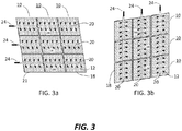
- Figs. 3A and 3B each illustrate an assembly of nine multi-layer fluid delivery devices 10.
- Horizontally positioned injection conduit members 20 are connected to conduit members 20 of adjacent devices to create a monolithic barrier structure, as illustrate in Fig. 3A ; while vertically positioned injection conduit members 20 are connected to conduit members 20 of adjacent devices to create a monolithic barrier structure, as illustrated in Fig. 3B .
- a grout, resin, cement, or other injection fluid 24 introduced 24 into ends of connected conduit members 20 will flow through the conduit members 20 and enter the intermediate open-matrix layers of the connected devices 10.
- Fig. 3A shows arrows for injecting fluid from the left side of the devices 10, injection fluid may also be simultaneously injected from the right side of the devices 10 as well.
- the numerous devices 10 of the invention can be connected together using waterproofing tape to connect the various first layers 12 of the devices 10 to each other and to connect the various second layers to each other.
- the tape can be used to seam the outermost edges of the conjoined first and second layers together (as designated at 18 in Fig. 3A ) so as to define a containment space into which the injection fluid may flow.
- One end of the injection conduit members 24 may be capped, clamped, or otherwise plugged so that fluid (e.g., resin, grout, concrete) injected into the tubing 24 under pressure is allowed to completely fill the device.
- fluid e.g., resin, grout, concrete
- Fig. 4 illustrates an exemplary injection conduit member 30 situated along an edge of a device 10 in parallel orientation with respect to the layers (e.g., 12) and intermediate , parallel to the intermediate open-matrix layer.
- the conduit member 30 is shown having openings 31 for communicating with the spaces within the open-matrix layer or layers 16 or for connecting to further conduit members that may be located within the intermediate open-matrix layer.
- the exemplary conduit member 30 shown in Fig. 4 is shaped as a tube, preferably although not necessarily having at least two flange members (designated at 32) to facilitate attachment and seaming of the conduit member 30 to the barrier injection device 10.
- the connector conduit members 30 can be used to inject a waterproofing resin or grout or other fluid into devices 10 that do not have integral injection conduit members 20, or into two or more devices each of which contain one or more injection conduit members.
- a tape may be used opposite against the conduit member 30 on the side opposite the flange 32 to provide a seal between the layer 12 and injection conduit member 30.
- a barrier of the present invention for creating a grout wall may be assembled at the construction site using (a) a multi-layer device that does not contain an injection conduit member; and (b) an injection conduit member that is installed along an edge of the device (See e.g., Fig. 4 ).
- Fig. 5 illustrates an exemplary injection conduit member 20, mentioned above, which employs concentric spiral wrap sleeves (designated at 34 and 36) to form tubing that is effective for conveying an injection fluid.
- the conduit member 20 comprises an outer spiral wrap sleeve member 36 surrounding an inner spiral wrap sleeve member 34. By tightly wrapping the inner spiral wrap 34, slit openings (designated as at 35) are formed in the inner spiral wrap sleeve 34.
- An outermost spiral wrap sleeve member 36 helps to control expansion of the inner sleeve 34 and prevents injection fluid from re-entering it.
- the inner 34 and outer 36 spiral wrap sleeves may have the same or opposite spiral directions.
- the material for making the spiral wrap sleeve may be chosen from a polyolefin (e.g., polyethylene, polypropylene, or mixtures thereof), a polyamide (e.g., nylon), or combinations thereof.
- another exemplary injection conduit member 20 comprises at least one and optionally two spiral wrap sleeve members, and further comprises an outer mesh sleeve member 40 to protect and/or to control expansion of inner spiral wrap sleeve member or members.
- the mesh sleeve member 40 may be made of a woven or braided material, and may comprise a polyolefin (e.g., polyethylene, polypropylene, or mixtures thereof), a polyamide (e.g., nylon), or combinations thereof.
- the conduit member 20 may comprise a spiral wrap member, optionally surrounded by a second spiral wrap member 38, and an outer mesh sleeve 40 surrounding the inner spiral wrap member.
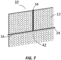
- Fig. 7 illustrates another exemplary device 10 of the invention having an injection conduit member 34 with a "T" shape (designated at 42), thus permitting an injection fluid to be conveyed in directions parallel to both the width and length dimension of the multi-layer fluid delivery device 10.
- the "T" shaped injection conduit may be located between first layer 12 (e.g., nonwoven) and the second layer (film not shown), or may be located outside of the device but against the first (e.g., nonwoven) layer 12.
- first layer 12 e.g., nonwoven
- injection fluid which is injected into the conduit 34 and through conduit openings (not illustrated for sake of simplicity) will be forced through the first layer 12 (nonwoven) and into the device 10.
- an assembly of two or more barrier devices 10 can be created by joining the openings 31 of an exemplary connector conduit member 30.
- the exemplary conduit member 30, in this case, is illustrated as tubing having openings 31 for conveying an injection fluid into other conduit members 34 or, alternatively, for using a vacuum (negative pressure) to pull injection fluid from the ends of other conduit members 34.
- the conduit member 30, as shown in Fig. 8 is located along an edge (width or length) of two adjacent devices (both designated as at 10).
- the connector conduit member 30 is shown having optional flanges 32, which can be created by attaching a tape or sheet upon which a two-sided tape can be used, to facilitate joining multi-layer devices (10) together.
- the devices (10) may have injection conduit members (34) located inside the devices or outside of the devices. Again, the conduit members can be taped against a nonwoven first layer of the device such that an injection fluid can flow out of the conduit members 34 and into the open-matrix layers of the devices 10.
- the first layer 12 is a non-woven material and the second layer 14 is a polymer film material, wherein the first and second layers 12/14 are generally co-extensive with each other, the device having generally parallel edges along its width and length dimensions.
- the multi-layer device 10 may have at least one injection conduit member 20 contained between the first and second layers 12/14 and/or against an edge or outward face of the first (nonwoven layer. At least one conduit member, as illustrated in Fig.
- the conduit member may extend the full width or length dimension of the device 10, with the conduit member comprising a tubing having slit openings for conducting an injection fluid between the first and second layers 12/14 and into the space defined by the open-matrix intermediate layer 16, the conduit member 20 having at least one surrounding layer to protect the openings of the inner slit openings from clogging.
- the injection conduit member 20 may be located outside of the device, such as against the outward face of the first layer 12 such that injection fluid exits the device and flows through the nonwoven material of the first layer 12 and into the open-matrix intermediate layer 16.
- the polymer film layer 14 optionally has a pressure-sensitive adhesive layer 22 attached on a face 14 opposite the open-matrix intermediate layer 16, to facilitate installation of the multi-layer device against a substrate.
- one end of the conduit member 20 member and the first and second layers 12/14 are sealed (See e.g., Fig. 1 at 18A and 18B) to define a containment cavity for the injection fluid.
- the sealing can be done at the construction site, such as by using a pinch clamp or stopper to close one end of the conduit member or members 20.
- Tape can be used to seal conduit members 20 located against the first (nonwoven) layer 12 and/or located at the edge of one or more multi-layer devices (10) to force injection fluid which is pumped through the conduit member 20 openings to flow into the open-matrix intermediate layer 16.
- the method for establishing a barrier assembly for post-installation in-situ incorporation of a grout, resin, cement, or other injection may comprise: connecting at least two devices 10 with an injection conduit member 30 having openings 31 in communication with the at least one injection conduit member 34 having openings for conducting an injection fluid between the first and second layers 12/14 of the at least two devices 10 and into the space defined by the open-matrix intermediate layers of the at least two devices 10.
- Fig. 9 is a cross-section plan diagram of a further exemplary multi-layer device 10 or assembly of the invention for creating a grout wall, which further illustrates concrete 44 placed against the device 10 after installation of the device against a substrate, such as a formwork, foundation, tunnel wall, or other existing structure.
- a substrate such as a formwork, foundation, tunnel wall, or other existing structure.
- injection fluid e.g., grout, resin, cement
- permeate out of the open-matrix layer 16 into void spaces 46 or other discontinuities in the concrete 44 which may be caused when concrete is poured or sprayed against rebar 43 which installed next to the installed device.
- the rebar 43 can block the spray path, and a void space 46 is created behind the rebar (designated at 43, adjacent the void space).
- the void spaces could allow water to penetrate laterally between the device 10 and the concrete 44.
- Fig. 9 also illustrates the use of side walls 18A and 18B which join the first layer 12 and second layer 14 and enable injection fluid to fill the open matrix layer 16 and permeate through the nonwoven first layer 12 and to fill in the void spaces (e.g., designated at 46) in the concrete 44.
- a continuous "grout wall" is established (e.g., against the concrete designated at 44) by the injection fluid which is present in the open-matrix layer 16, nonwoven first layer 12, and void spaces (46) which are in communication with the non-woven first layer 12.
- injection conduit members 20 may be located in any number of positions in or adjacent to the structure of the multi-layer barrier device 10.
- the most preferred location, as designated at 20A, is to have the injection conduit tubing located parallel with respect to, and between, the first layer 12 (e.g., nonwoven or fabric layer) and second layer 14 (e.g., water-impermeable polyolefin film), and also between containment side wall 18B and non-woven side wall 18A.
- the injection conduit tubing may also be located adjacent the side edge ("side-edge") of the barrier device 10, as designated at 20B, where the non-woven side allows for flow out of the tubing 20B and into the open-matrix layer 16.
- the side-edge conduit tubing 20B is secured to the barrier using a woven or non-woven strip of material (12A) connected to the first 12 and second 14 layer, which strip is in turn further secured using a tape 47.
- Fig. 10 also illustrates a third option whereby injection conduit tubing (as designated at 20C, is located against the face of the outer-most layer 12 which is made of woven or non-woven material.
- the face-mounted conduit tubing 20C can be secured to the woven or non-woven face of the first layer 12, using a woven or non-woven fabric 12A (which for example can be the same non-woven material used for the first layer 12), and this can in turned be secured further using tapes (47) similar to the side-edge tubing 20B situation explained above.
- a woven or non-woven fabric 12A which for example can be the same non-woven material used for the first layer 12
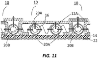
- FIG. 11 shows in cross-section a further exemplary embodiment wherein a multi-layer barrier assembly, comprising two or more barrier devices (designated variously as at 10) are mounted in adjacent fashion upon a substrate or surface.
- at least one barrier device 10 is shown having one or more internal injection conduit tubing members (20A) for introducing an injection fluid into the open-matrix layer 16 between the first layer 12 and second 14 layer.
- the first layer made for example of a non-woven material, is shown folded around its lateral edges to define opposing side-edges of non-woven material that connect (or could be adhered or melted) to join the second layer 14.
- Further injection conduit tubing members 20B are located at the side-edges adjacent to the individual barrier devices (10) such that injection fluid can be flowed through the adjacent devices 10 through fabric (e.g., nonwoven) material (as illustrated by arrows emanating out of the tubing designated at 20B).
- Strips of woven or non-woven material can be used to prevent concrete from clogging the tubing 20B while allowing injection fluid to be pumped against the concrete and thereby form a continuous grout wall with respect to injection fluid that permeates through the first layer and fabric strips 12/12A.
- the second layer 14 is illustrated as a water-impermeable continuous film (e.g., polyolefin film), it is possible to use strips of film that are adhered together, such as by an adhesive layer 22. It is possible, in any of the specific exemplary aspects described above or hereafter, that an impermeable film 14 (preferably having a pre-attached pressure sensitive adhesive 22) be applied first against a substrate or surface; and then individual multi-layer barrier units 10 can be adhered or formed against the installed water-impermeable film layer 14 and adhesive layer 22, by subsequent application of open-matrix structure to form the open-matrix layer 16, followed by placement of injection tubing 20A, and a (non-woven) first layer 12 to enclose the injection tubing 20A and define a containment space so that an injection fluid can fill the open-matrix layer 16 (shown with an open matrix structure for spacing apart the first layer 12 and second layer 14.
- an impermeable film 14 preferably having a pre-attached pressure sensitive adhesive 22
- the fabric strip 12A is made of the same material (e.g., nonwoven) as the first layer 12, and attached using adhesive to secure the strip 12A to the first (outermost face) layer 12.
- the kit may comprise two fluid delivery devices (e.g., as designated at 10 in Figs. 1 , 2 , or 9 ) and a separate connector conduit member 30 as illustrated in Fig. 8 for attaching two or more devices 10 together.
- two fluid delivery devices e.g., as designated at 10 in Figs. 1 , 2 , or 9
- a separate connector conduit member 30 as illustrated in Fig. 8 for attaching two or more devices 10 together.
- kits can comprise a barrier device 10 such as illustrated in Fig. 10 , which has an internally located injection tubing 20A, and separate tubing with fabric strips for side-edge placement (of tubing designated at 20B in Fig. 10 ), face-side placement (of tubing designated at 20C in Fig. 10 ), or a combination of all three tubing placement locations (20A/20B/20C).
- a barrier device 10 such as illustrated in Fig. 10 , which has an internally located injection tubing 20A, and separate tubing with fabric strips for side-edge placement (of tubing designated at 20B in Fig. 10 ), face-side placement (of tubing designated at 20C in Fig. 10 ), or a combination of all three tubing placement locations (20A/20B/20C).
- kits can comprise at least two barrier devices which comprise at least three sides which are made of woven or non-woven material (as designated at 10/12 in Fig. 11 ), wherein separate injection tubing 20B can be sealed, preferably using fabric strips, to protect side-edge tubing 20B from clogging from concrete poured against the outer layer 12 of the device 10.
- FIG. 12 Further exemplary embodiments of the present invention involve a system wherein the multi-layer barrier is injected with waterproofing grout fluid using a grout pump, injection fluid components, and catalysts (gel activators).
- a grout pump injection fluid components
- gel activators catalysts
- FIG. 12 if no activator is pre-applied or pre-installed in an installed barrier device (10), two different injection fluid Components A and B (54, 55) having two Activators A and B (55, 57) would be mixed together and pumped (52) into an installed barrier device (10).
- Commercially available mixer/pump (52) would combine injection fluid Components A and B (54, 56): wherein Activator A (55) is premixed with Component A (54), and Activator B (57) is premixed with Component B (56).
- Component A could comprise an acrylate or methacrylate oligomer, an acrylate or methacrylate monomer, an acrylic acid salt, a methacrylic acid salt, and water; while Component B could comprise an emulsion of a polymer which may be further diluted with water; and Activator B could be a radical initiator which reacts with Activator A to form free radicals that initiate the polymerization of component A, and Activator A could be an amine.
- known multi-component grout systems could be used in combination with a barrier device 10 of the present invention in accordance with any of the foregoing first through twenty-fifth exemplary aspects described above).
- the multi-layer barrier device 10 can further comprise an injection fluid gelation activator (hereinafter “gel activator”) within the device between the first layer and second layer.
- gel activator would function to initiate or accelerate gelation, viscosity increase, and/or hardening of the injection fluid material. Locating a gel activator, such as a resin, hardener, catalyst or accelerator, within the open matrix space would avoid the need to use a multicomponent grout system as depicted in Fig. 12 .
- a single component grout pump could be used whereby injection fluid could be delivered at very high fluidity and be easy to pump; and, once the injection fluid has entered into the multi-layer barrier device, the injection fluid would come into contact with gel activator located in the multi-layer barrier device and start to increase in viscosity (gel).
- the barrier devices 10 of the invention may comprise a gel activator located on the open-matrix structure 16 between the first and second layers 12/14.
- the gel activator may be coated against the film layer 14, the open matrix layer 16 (i.e., the open mesh or nonwoven structure which defines the open cavity between layers 12 and 14), the outer layer 12, or any combination of these.
- the open-matrix structure 16 is a three-dimensional filament structure polyamide matting, having a thickness of 8-25 mm, supplied in roll form, which is attached to the first layer 14 and coated with gel activator, in the manner illustrated in Fig. 13 .
- a gel activator is applied, such as by spray application or brushing, onto an exemplary open-matrix structure, e.g., non-woven geotextile structure, before the outward face (nonwoven, not illustrated) is applied.
- exemplary open-matrix structure e.g., non-woven geotextile structure
- Other application methods may be used including dipping, extrusion, and air knife coating. While this concept allows for very flowable injection resins to be pumped into multi-layer barrier devices, and would be preferred for the use of parallel injection tubes 30; this concept can also be used for barrier devices that use outwardly extending (perpendicular) tubing, such as previously disclosed by Iske et al. in US Patent 7,565,779 B2 .
- This concept may also be used for multi-layer barrier devices of the present invention and also of Iske et al. that do not use tubing or pipes to introduce injection fluid, which is introduced into the barrier devices through holes drilled into concrete cast against the installed barrier device, or which is otherwise introduced through sides of the installed barrier device.
- Exemplary grout or resin components and gel activators contemplated for use in the invention include, but are not necessarily limited, to acrylics, polyurethanes, epoxies, cementitious and (sodium) silicates, for example, and may employ two components that are mixed before pumping and pumped to the desired area/location where the grout wall curtain is to be established.
- one of the components may be located or positioned within the open matrix structure (e.g., ENKA TM brand geotextiles or mats have an open structure and inner surfaces which could be coated with one of the components).
- a gelation activator is pre-applied within the open-matrix layer defined between the first and second layers (hereinafter "gel activator").
- the gel activator functions as an accelerator, catalyst, hardener, resin and/or curative agent to increase or to initiate gelation (e.g., hardening, stiffening, polymerization) of the injection fluid once it is introduced into the open matrix layer.
- the injection fluid could be a polyol resin
- the gel activator could be an isocyanate functional resin, to generate a polyurethane grout wall composition within the barrier device.
- the injection fluid could be an isocyanate resin
- the gel activator could be an amine resin, to generate a polyurea grout wall within the barrier device.
- An amine gel activator or a free radical gel activator could be used for polyacrylate-containing injection fluids.
- a still further example involves use of an epoxy resin injection fluid and amine resin as gel activator.
- the gel activator for hydratable cementitious injection fluids could be a set accelerator (e.g., calcium nitrite and/or nitrate) to quicken the setting of the cement.
- the injection fluid may comprise a sodium silicate solution and the gel activator may comprise an acid or an alkaline earth salt or an aluminum salt.
- the gel activator is pre-installed or pre-applied (e.g. coated, sprayed, brushed) into the open-matrix layer structure, such as into a non-woven geotextile mat used for separating the first and second layers of the barrier device. Consequently, a highly flowable injection fluid can be introduced into the barrier device without the need for high-powered, multi-component pump equipment.
- a simple single-component pump may be used. Upon contact with the gel activator located within the open-matrix layer of an installed barrier device (10), the injection fluid will begin to gel (i.e., to increase in viscosity) and ensure that a grout wall is established against concrete that was cast against the installed barrier (10).
- a first example injection fluid comprises Component A (54), Activator A (55), and Component B (56), borrowing the corresponding numbers from Fig. 12 .
- Component A may comprise an acrylate or methacrylate oligomer, an acrylate or methacrylate monomer, an acrylic acid salt, or a methacrylic acid salt
- Component B may comprise an emulsion of a polymer
- Activator A may comprise an amine.
- Activator B (57) is coated within the first and second layers within the barrier device (10) and may comprise a radical initiator which reacts with Activator A to form free radicals that initiate the polymerization of Component A.
- injection fluid 24 can be pumped or metered into the barrier device (10) conveniently using a grout pump (50) as shown in Fig. 14 .
- the injection fluid 24 may comprise Component A (54), Component B (56), and Activator B (57) (again to borrow the numbering from Fig. 12 ), wherein Component A comprises an acrylate or methacrylate oligomer, an acrylate or methacrylate monomer, an acrylic acid salt, or a methacrylic acid salt; Component B comprises an emulsion of a polymer which may be further diluted with water; and Activator B comprises a radical initiator which reacts with Activator A to form free radicals that initiate the polymerization of component A.
- the Activator 55 is coated within the barrier device 10 (between the first and second layers), and may comprise an amine.
- an exemplary system and method of the invention can involve minimal components to pump the injection fluid 24 using a grout pump 50 into the barrier device (10) which is impregnated with a gel activator.
- some portion of the gel activator can be mixed into the injection fluid at a point in the injection conduit system before the injection fluid enters into the open matrix, so as to provide more time for the chemical reaction to occur.
- a designer or operator of the system has flexibility in terms of being able to adjust when, where, and how much of the gel activator is introduced to the injection resin, thereby enhancing control over the viscosity or other rheological characteristics of the injection resin composition during the installation process.
- the multi-layer barrier device 10 can have an impermeable film (14) and nonwoven face (12) and an open-matrix structure (16) defining an open space between layers 12 and 14, as illustrated in Fig. 1 , and optionally one or more tubes, parallel or perpendicular to the layers 12/14 for introducing an injection fluid into the open space; and a gel activator located within the open space between layers 12 and 14.
- the gel activator may, for example, be pre-installed on an open-matrix structure (16) which has been coated with gel activator. This will allow a highly flowable injection fluid to be introduced through tubing that is perpendicular to the layers 12/14 in the manner taught by Iske et al. in US Patent 7,565,779 B2 , or through tubing that is parallel to layers 12/14, as described and illustrated in any of the exemplary first through twenty-fifth aspects above.
- an exemplary device for post-installation in-situ barrier creation can comprise a multi-layer fluid delivery device comprising first and second layers defining an intermediate open-matrix layer for an injection fluid; the first layer having an inwardly facing surface and an outwardly facing surface, the first layer being permeable to the injection fluid but at least nearly impermeable to a structural construction material to be applied against the outwardly facing surface of the first layer, and the second layer being water-impermeable and having an inwardly facing first side and an outwardly facing second side, the inwardly facing first side of the second layer being affixed, directly or indirectly to the inwardly facing surface of the first layer such that all or a substantial portion of the second layer is spaced apart from the first layer, using an open-matrix structure to create air space between the first layer and the second layer and thereby defining an open-matrix layer for conducting an injection fluid between said first and second layers; and a gel activator located within the space defined by the open-matrix structure.
- the barrier device of the invention can further comprise tubing for introducing an injection fluid into the device, the tubing being disposed (i) in parallel orientation with respect to the first and second layers, (ii) perpendicularly with respect to the first and second layers, or (iii) in both parallel and perpendicular orientations with respect to the first and second layers.
- the the exemplary barrier devices 10 can be shipped or sold together along with injection fluids that correspond with gel activators contained in the device 10.
- gel activator located within the cavity of the multi-barrier device, preferably located on the open-matrix structure (26) is particularly advantageous when internal conduit tubing (20) is used for conveying injection fluid into the device, as described in the first through twentieth exemplary aspects, as highly flowable injection fluid can be used, and this would greatly facilitate quick and efficient completion of a grout wall waterproofing project, and ensure that the injection fluid would be able to flow into even the minutest of cracks in the concrete situated against the non-woven face 12 of the barrier device 10.
- the barrier wall device can be connected to a source of positive pressure, negative pressure (e.g., vacuum), or combination of positive pressure and negative pressure sources.
- a source of positive pressure e.g., positive pressure, negative pressure (e.g., vacuum), or combination of positive pressure and negative pressure sources.
Description
- The invention relates to a barrier device for post-installation injection of a waterproofing fluid; and, more particularly, to a multi-layer device having first and second layers defining an intermediate open-matrix layer, and at least one injection conduit member disposed in parallel orientation with respect to the first and second layers to permit a waterproofing fluid to be injected into the open-matrix layer. The at least one injection conduit member may be located between the first and second layers and thus within the open matrix layer, at the edge of the multi-layer device and adjacent to an open matrix layer, along an outer face of the first layer if the first layer is made of nonwoven or woven fabric, or combination of these locations, whereby an injection fluid can be conveyed through the conduit member and into the open matrix layer.
- The use of multi-layer devices for post-installation, in-situ creation of barriers for waterproofing of concrete constructions is known. An applicator places such devices against a substrate, such as formwork or existing wall, and applies concrete against the devices. Thereafter, an applicator can inject a waterproofing fluid into the devices. The waterproofing fluid may comprise waterproofing resins or cements, insecticides, mold preventatives, rust retardants, and the like, for creating a watertight barrier, or so-called "grout wall," to protect the concrete structure. The injection of the fluid allows for remedial waterproofing treatment after installation of the device and after spraying or casting concrete against the device.
- Brian Iske and others disclosed various devices for the creation of grout walls in
US Patent Nos. 7584581 ,7836650 ,7900418 , and8291668 , owned by the common assignee hereof. The grout wall devices can be attached to the exterior of a shoring system, a tunnel excavation wall, a concrete formwork, or other substrates or structures. - Characteristic of the Iske devices were a plurality of injection tubes that jutted perpendicularly out of the outermost layer of the multi-layered devices. The orientation and placement of these perpendicularly, outward-extending tubes enabled injection of the waterproofing fluid (e.g., grouts, resins, etc.) into the device after concrete was applied against the exterior of the installed multi-layer device. After the concrete was cast or sprayed against the installed device, Iske et al. taught that applicators could pump the waterproofing composition into the multi-layered device and thus completely fill the interior of the multi-layer device using spaced-apart tubes or pipes. The tubes or pipes extended perpendicularly through the outermost layer of the devices and through the placed concrete structure and required placement to ensure that the injection fluid would be able to fill completely the multi-layer device behind the concrete (See e.g.,
US Patent 7,836,650 atFigs. 5-6 ). - The present inventors believe that such prior art multi-layer grout wall devices, due to the large number of perpendicularly extending tubes or pipes, required enormous preparation work on site, even when the devices were installed as pre-assembled integral units. The use of the perpendicularly extending tubing required a lot of preparation and steps during the injection process to ensure that a continuous grout wall could be established between the devices and the concrete placed against the devices.
-
JP2004060217A - The invention is defined in
claims - In surmounting the deficiencies of the prior art, the present invention provides a multi-layer device that enables faster and more convenient installation of a grout wall system, and particularly for establishing a grout wall using an assembly of such multi-layer devices.
- An exemplary device of the invention for post-installation in-situ barrier creation, comprises a multi-layer fluid delivery device and at least one injection conduit member, wherein: the multi-layer fluid delivery device comprises first and second layers defining an intermediate open-matrix layer for an injection fluid; the first layer has an inwardly facing surface and an outwardly facing surface, the first layer being permeable to the injection fluid but at least nearly impermeable to a structural construction material to be applied against the outwardly facing surface of the first layer, and the second layer is water-impermeable and has an inwardly facing first side and an outwardly facing second side, the inwardly facing first side of the second layer being affixed, directly or indirectly to the inwardly facing surface of the first layer such that all or a substantial portion of the second layer is spaced apart from the first layer, using an open-matrix structure to create air space between the first layer and the second layer and thereby defining the open-matrix layer for conducting the injection fluid between said first and second layers; the at least one injection conduit member is disposed in parallel orientation with respect to the first layer and second layer, the at least one injection conduit member being for conveying an injection fluid into the open-matrix layer air space; the at least one injection conduit member is: (i) located within the open-matrix layer and thus between the first and second layer, (ii) located adjacent the open-matrix layer; (iii) located against the outwardly facing surface of the first layer which is permeable to injection fluid; or (iv) located in a combination or all of the foregoing locations (i), (ii), and (iii); and the at least one injection conduit member comprises polymer tubing having openings which are resiliently movable from a closed to open position when the conduit member is filled with an injection fluid under positive pressure.
- The injection fluid may be chosen from waterproofing resin, grout, cement, insecticide, mold preventative, rust retardant, and mixtures thereof.
- In further exemplary embodiments, the first layer is permeable to the injection fluid and nearly impermeable to the structural construction material (e.g., concrete), and comprises a non-woven or woven fabric; while the second layer is water-impermeable, and comprises a polymer film (e.g., polyethylene, polypropylene).
- While the invention contemplates that the multi-layer device can be assembled from separate components at the construction site, the inventors believe that it is more convenient, efficient, and faster to use pre-assembled multi-layer devices, so that installation effort and time are minimized. In either case, one creates an "in situ" (or "in place") barrier system that defines a confined flow area for injection fluids such as waterproofing resins and grouts.
- The present invention has particular value in vertical wall applications, especially for sealing to prevent leakages at cold joints, as defined between concrete floors and subsequently poured vertical walls. The device is assembled or installed as a pre-assembled unit against a substrate (e.g., excavation, existing wall or foundation, formwork or mold, tunnel wall, etc.), and, subsequently, concrete is cast or sprayed against its outward-facing layer. The device may also be assembled or installed in horizontal applications, such as sub-layer or subflooring for concrete slabs, decks, and floor applications, including applications where the existence and location of joints and segment dimensions are not predictable or uniform. In either horizontal or vertical applications, the devices and assemblies of the invention can protect against moisture penetration due to crack formations or other leakage pathways formed within or between concrete structures.
- In other exemplary embodiments, the outward face layer of the multi-layer device is preferably porous, such as in a nonwoven or woven fabric, which allows the injection fluid to fill in the open-matrix intermediate layer and flows through the outward face porous layer to fill in voids or discontinuities in the construction material (e.g., concrete) that is cast or sprayed against the multi-layer device.
- The present invention also has particular value in shotcrete applications, wherein concrete is sprayed against the outward face of the device. When the device of the invention is installed against a wall, and concrete is poured or spray-applied against rebar adjacent the installed device, the device will allow a subsequently injected resin or grout to permeate through the outward face porous layer and fill in "shadow" areas where the rebar interrupts the path of the poured or sprayed concrete (or shotcrete), thereby creating a full contact seal with the concrete (or shotcrete).
- In other embodiments, the barrier devices of the present invention having the at least one injection conduit member in parallel orientation with respect to the first and second layers are provided in rollable or stacked form that can be used conveniently and quickly at the construction site. In other words, two or more pre-assembled multi-layer fluid delivery units can be connected together to form a monolithic barrier layer wherein their at least one injection conduit member(s) are connected to permit an injection fluid (e.g., grout, resin, cement) to be pumped through and/or into several barrier devices at once, thereby creating a monolithic water-resistive curtain over an area that is larger than an individual barrier device. The concrete which is subsequently cast or sprayed against the installed barrier devices allow the in-situ barriers to stay in place during fluid injection, and to resist the compressive pressure required to inject the fluid into the open-matrix intermediate layer and through the permeable outward porous (e.g., woven or nonwoven) fabric which comprises the outward face layer.
- In further exemplary multi-layer barrier devices of the invention, the layer installed against a formwork or other substrate comprises a water-impermeable polymer film (e.g., polyolefin), and the layer disposed outwards for bonding with cast or sprayed concrete comprises a non-woven material (e.g., polypropylene, nylon, polyamide). The film layer side of the device can be attached to formwork, an existing wall, or other substrate using a two-sided tape or pre-attached pressure-sensitive adhesive layer. The outward-facing non-woven layer, on the other hand, allows for permeation of the injection fluid (e.g., grout, resin, cement) into and out of the intermediate open-matrix layer, while essentially blocking concrete or other construction material cast against the barrier device from entering into the open-matrix intermediate layer.
- The present invention also provides a method for creating an in-situ barrier device (or assembly), wherein the above barrier device is attached or assembled against an excavation wall, lagging form, or shoring system, where concrete is thereafter applied (e.g., sprayed, poured) against the outer layer of the barrier device; and an injection fluid is subsequently injected through the at least one injection conduit and into the space defined by the open-matrix intermediate layer.
- Especially preferred devices of the invention comprise one or more injection conduit members disposed in parallel orientation with respect to the first and second layers, and can be (i) located within the open-matrix layer and thus between the first and second layer, (ii) located adjacent the open-matrix layer (along an edge of the device); (iii) located against the outwardly facing surface of the first layer which is permeable to injection fluid; or (iv) located in a combination or all of the foregoing locations (i), (ii), and (iii).
- The present invention avoids the inconvenience of having to install numerous injection tubes extending perpendicularly across the outward face of the device, as well as the inconvenience of applying concrete around the perpendicularly extending tubes.
- In a further exemplary multi-layer device of the invention, a gelation activator is pre-applied within the open-matrix layer defined between the first and second layers (hereinafter "gel activator"). The gel activator functions as an accelerator, catalyst, hardener, resin and/or curative agent to increase or to initiate gelation (e.g., hardening, stiffening, polymerization) of the injection fluid once it is introduced into the open matrix layer. For example, the injection fluid could be a polyol resin, and the gel activator could be an isocyanate functional resin, to generate a polyurethane grout wall composition within the barrier device.
- As another example, the injection fluid could be an isocyanate resin, and the gel activator could be an amine resin, to generate a polyurea grout wall within the barrier device. An amine gel activator or a free radical gel activator could be used for injection fluids that were based on polyacrylate. A still further example involves use of an epoxy resin injection fluid, and an amine resin as gel activator.
- As another example, the gel activator for hydratable cementitious injection fluids could be a set accelerator (e.g., calcium nitrite and/or nitrate) to quicken the setting of the cement. As yet another example the injection fluid may comprise a sodium silicate solution and the gel activator may comprise an acid or an alkaline earth salt or an aluminum salt. The gel activator is pre-installed or preapplied (e.g. coated, sprayed, brushed) into the open-matrix layer structure, such as into a non-woven geotextile mat used for separating the first and second layers of the barrier device. Consequently, a highly flowable injection fluid can be introduced into the barrier device without the need for high-powered, multi-component pump equipment. A simple, single component pump equipment is used. Upon contact with the gel activator located within the open-matrix layer, the injection fluid will begin to gel (e.g., assume higher viscosity) and ensure that a grout wall is established against concrete that was cast against the installed barrier.
- The present inventors believe that the use of a pre-installed gel activator will benefit the use of the herein-described barrier devices having injection conduit members disposed in parallel orientation with respect to the first and second layers. The pre-installed gel activator will also benefit conventional grout wall barrier designs (e.g.,
US Patent 7,565,799 ) which employ tubes extending perpendicularly from the structure. Hence, another exemplary multi-layer fluid delivery device of the present invention comprises first and second layers defining an intermediate open-matrix layer for an injection fluid; the first layer having an inwardly facing surface and an outwardly facing surface, the first layer being permeable to the injection fluid but at least nearly impermeable to a structural construction material to be applied against the outwardly facing surface of the first layer, and the second layer being water-impermeable and having an inwardly facing first side and an outwardly facing second side, the inwardly facing first side of the second layer being affixed, directly or indirectly to the inwardly facing surface of the first layer such that all or a substantial portion of the second layer is spaced apart from the first layer, using an open-matrix structure to create air space between the first layer and the second layer and thereby defining an open-matrix layer for conducting an injection fluid between said first and second layers; and at least one injection conduit member disposed in parallel orientation with respect to the first layer and second layer, the at least one injection conduit member for conveying an injection fluid into the open-matrix intermediate layer air space; and the at least one injection conduit member being (a) located within the open-matrix layer and thus between the first and second layer, (b) perpendicular and connected to and disposed outside of the open-matrix layer; or (c) both (a) and (b); and having a gel activator located within the open-matrix structure. Preferably in the barrier devices and method a gel activator is pre-installed, wherein gelation is initiated or accelerated in injection fluids introduced through parallel and/or perpendicular injection tubes, or even where injection fluid is introduced without injection tubes but through holes drilled in concrete that was hardened against the installed barrier device. - Further features and benefits of the invention are described hereinafter.
- The present invention may be more readily comprehended when the following written description of exemplary embodiments is considered in conjunction with the drawings, wherein
-
Fig. 1 is a diagram of an exemplary multi-layer device of the invention having at least one injection conduit member such as polymer tubing (openings not shown); -
Fig. 2 is a perspective illustration of an exemplary multi-layer device of the invention whereby an injection fluid can be introduced into an intermediate open-matrix layer through openings in the injection conduit member (e.g., polymer tubing); -
Figs. 3A and 3B are perspective illustrations of exemplary multi-layer device assemblies of the invention wherein conduit members are shown in an interconnected arrangement; -
Fig. 4 is a perspective illustration of an exemplary injection conduit member with flange for connecting other multi-layer devices to a common conduit member; -
Figs. 5 and 6 are exploded diagrams of other exemplary injection conduit members of the invention having one or more sleeves; -
Fig. 7 is a plan diagram of another exemplary multi-layer device of the invention wherein an exemplary injection conduit member comprises a "T" structure within the device; -
Fig. 8 is an exploded plan diagram of an exemplary connector/injection conduit member for connecting two multi-layer devices together; -
Fig. 9 is a cross-section plan diagram of a further exemplary multi-layer device of the invention, which further illustrates concrete placed against the device after installation of the device against a substrate and after installation of rebar (shown in cross-section); -
Fig. 10 is a cross-section plan diagram illustrating various locations of injection conduit tubing in, on, or alongside an exemplary multi-layer barrier device; -
Fig. 11 is a cross-section plan diagram illustrating exemplary adjacent installation of exemplary multi-layer barrier devices; -
Fig. 12 is a diagram of a multi-component grout system of the prior art which requires mixing before being pumped into an (installed) multi-layer barrier device using separate mixing chamber before the grout pump; -
Fig. 13 is a diagram of the present invention wherein a gel activator is applied onto an exemplary open-matrix structure, e.g., non-woven geotextile structure, before the outward face (nonwoven, not illustrated) is applied; and -
Fig. 14 is a diagram of a grout system of the present invention wherein injection fluid is pumped into an exemplary multi-layer barrier devices of the invention, which are preimpregnated with a gel activator. - The present invention relates to a multi-layer assembly or device for a post-installation in-situ barrier, as well as a method for assembling the barrier, using one or more injection conduit members that are parallel to the major faces or layers of the assembly or device, in contrast to the prior art use of perpendicularly extending pipes as taught by Iske et al. as mentioned in the Background section.
- The terms "assembly" and "device" may be used interchangeably throughout this specification. Ideally, relatively little assembly of an individual multi-layer device is required at the construction site, although the establishment of a grout wall against concrete that is poured or sprayed against a number of such individual multi-layer devices will require some "assembly" to join individual multi-layer devices together, including injection conduit members to permit filling two or more of the devices using a single source of injection fluid. (This will be described further hereinafter during discussion of
Figs. 3A and 3B ). - As will be explained in further detail hereinafter, two or more multi-layered devices can be joined together, thereby allowing for the creation of a grout wall to seal against subsequently applied concrete, using injection conduit members which can be (i) located within the open-matrix layer and thus between the first and second layers of the multi-layered device, (ii) located adjacent the open-matrix layer at an edge of one or more multi-layered devices; (iii) located against the outwardly facing surface of the first layer(s) which is permeable to injection fluid; or (iv) located in a combination or all of the foregoing locations (i), (ii), and (iii).
- For example, a barrier device can be assembled at a construction site by providing the multi-layer device having a first layer (e.g., a nonwoven which is permeable to a waterproofing grout, resin, cement, or other injection fluid), a second layer (e.g., a water-impermeable polymeric film), and an open-matrix structure for connecting the first and second layers together but defining a space for filling with injection fluid; and an injection conduit (e.g., spiral wrap tubing) can be taped against the first layer (nonwoven) in a manner to allow injection fluid to be pumped through the nonwoven first layer so as to fill the intermediate open-matrix layer and to fill any gaps or discontinuities in concrete which is applied against the outer layer of the device.
- As another example, the barrier device can be adhered in strip form against a substrate, and an injection conduit member can be placed next to one or both edges along the strip, and taped in place, such that injection fluid can be pumped through and out of the injection conduit member and into the intermediate open matrix layers of the adjacent barrier device or devices.
- As a further example, the multi-layer barrier device may be pre-assembled having at least one integral injection conduit member between the first and second layers and thus embedded already within the intermediate open-matrix layer. This may facilitate installation, as well as waterproofing performance, because the applicator may also install additional injection conduit members in parallel fashion along an edge and/or outward face of the barrier devices, whereby an injection grout, cement, resin, or other fluid can be introduced from openings along the length of the injection conduit member into spaces within the intermediate open-matrix layers of the barrier devices.
- As shown in the plan cross-sectional diagram of
Fig. 1 , anexemplary device 10 for post-installation in-situ barrier creation comprises afirst layer 12 andsecond layer 14 which define an intermediate open-matrix layer 16, and at least oneinjection conduit member 20 that is disposed in parallel orientation with respect to and between the first andsecond layers 12/14. In further exemplary embodiments, the length of the at least oneconduit member 20 is preferably substantially coextensive with a width or length of thedevice 10. The at least oneinjection conduit member 20 has openings (not shown in this view) for introducing an injection fluid between thefirst layer 12 andsecond layer 14 and into the spaces within the open-matrixintermediate layer 16. - In further exemplary devices or assemblies of the invention, the
first layer 12 of the at least two spaced-apart layers is preferably non-permeable or semi-permeable to the injection fluid which is introduced into the intermediate open-matrix layer 16; while the second 14 of the at least two spaced-apart co-extensive layers is preferably a polymer film which is non-permeable to the injection fluid which is introduced into the intermediate open-matrix layer 16. For example, thefirst layer 12 can be a non-woven synthetic fabric of the kind used for bonding with fresh concrete cast or sprayed against it and allowed to cure into a hardened state. - In a further exemplary embodiment, a pressure-
sensitive adhesive layer 22 may be attached to thesecond layer 14 to facilitate installation of the device orassembly 10 against a substrate, such as an excavation wall, a concrete wall or foundation, a formwork, a scaffolding structure, or other mounting surface. -
Fig. 1 also illustrates the exemplary use of optional containment members (designated at 18A and 18B) for enclosing the space defined by the open-matrix layer 16 that is intermediate between thefirst layer 12 andsecond layer 14. The containment layers 18A/18B may comprise, for example, an adhesive tape for sealing the edges and thereby joining thefirst layer 12 andsecond layer 14. Alternatively, thecontainment members matrix layer 16 and attaching the extended sides (18A/18B) onto thefirst layer 12 of thebarrier device 10, either at or before installation. - In other exemplary embodiments, the
first layer 12 is preferably made from a synthetic felt or other non-woven fiber material, which is permeable to the injection grout, resin, cement or other fluid, but partly impermeable to fresh concrete that is cast against it. By "partly impermeable," it is intended that the fresh concrete is able to flow into interstices between the fibers of the felt or non-woven fiber material and to create a bond with the concrete when the concrete becomes hardened; and it is preferable to select the felt or non-woven fiber material such that the concrete does not entirely penetrate into the intermediate open-matrix layer 16 thereby to prevent the grout, resin, or other injection fluid from being able to fill up the spaces defined by theopen matrix layer 16 within thebarrier device 10, or to block the injection fluid from permeating the nonwoven, felt, or other fiber material which constitutes thefirst layer 12 and from filling gaps or discontinuities between the applied concrete and thefirst layer 12. - Various
exemplary structures 16 can be used for spacing apart the first andsecond layers 12/14 and defining the space within the intermediate open-matrix layer 16. For example, inUS Patent 7,565,779 , Iske et al. taught the use of frusto-conical shaped structures in addition to other protuberances, wave-shaped ribs, and geotextile non-woven layers. Atcolumn 10, lines 3 and following, Iske et al. identified commercially available construction drainage products that could be utilized in forming the open-matrix layer, for example, Colbond Enkadrain®, Pozidrain®, Terradrain®, Senergy®, Tenax®, Blanke Ultra-Drain®, AmerDrain®, Superseal SuperDrain®, J-Drain®, Viscoret® dimpled membrane, Terram® drainage composites, and Delta®-MS drainage membranes. The present inventors consider these various brands of geotextile products to be suitable for use in the present invention, and their selection would be subject to the preference of the device designer, assuming compatability with the size of internal injectionfluid conduit tubing 20 used between the first andsecond layers 12/14 of thebarrier device 10. - For exemplary intermediate open-
matrix layers 16 having a fast filling area for containing the injection fluid while providing rollability and sufficient structure to the multi-layer device, the present inventors contemplate the use of a three-dimensional membrane with open cell structure formed by continuous extrusion of two intersecting high density polyethylene (HDPE) strands to form a high profile, biaxial netlike mesh. The polymer strands may intersect randomly, and the form the shape of evenly spaced ribs or undulations, for spacing apart thefirst layer 12 andsecond layer 14, and permitting air channels having high capacity for the injection of chemical fluids such as grouts, resins, and cements which are typically used in waterproofing. The present inventors believe that three-dimensional geosynthetic textiles provide high fluid flow characteristics in both machine and cross directions without generating unnecessary flow resistance. Such open matrix structures will allow uniform flow of the injected fluid and create a curtain wall (e.g., chemical grout) in every direction. - The preferred thickness of this exemplary open-matrix layer is about 3.18 mm to 9.53 mm (1/8 inches to 3/8 inches). The density of the open-matrix layer may, for example, be in the range of 215 gm/m2 to 861 gm/m2 (20 gm/ft2 to 80 gm/ft2), more preferably between 323 gm/m2 to 753 gm/m2 (30 gm/ft2 to 70 gm/ft2), and most preferably between 484 gm/m2 to 646 gm/m2 (45 gm/ft2 to 60 gm/ft2).
- As mentioned above, the
second layer 14 is preferably a water-impermeable polymer film (e.g., polyolefin). More preferably, bothfirst layer 12 andsecond layer 14 will each have linear edges along their respective width and length dimensions. If aninjection conduit member 20 is positioned parallel to one of the width or length linear edges of thedevice 10, it may comprise a plurality of openings to permit an injection fluid to be introduced into the intermediate open-matrix layer 16 of a givendevice 10, or have separate holes or "T" or "X" joints to permit fluid communication/connection to injection conduit members that are located within thedevices 10. - As shown in
Fig. 2 , an exemplary multi-layerfluid delivery device 10 of the invention comprises at least oneinjection conduit member 20 positioned between the at least two spaced-apart first andsecond layers 12 and 14 (where only thefirst layer 12 is illustrated). In this embodiment, the one or more injection conduit member(s) is/are contained integrally within the intermediate open-matrix layer 16 and preferably shipped as a pre-assembled unit. Theinjection conduit member 20 may comprise a flexible plastic (e.g., nylon)tubing having openings 21, such as slits, which move resiliently into an opened position when injection fluid which is pumped into an end of the piping 24 to permit the injection fluid (26) to exit into the open-matrix layer (16). Theslit openings 21 should return to a closed position when the injection fluid is no longer subject to pressure. - In further exemplary embodiments, the
injection conduit member 20 can be formed by spiral wrapping of a ribbon shaped polymer to form a tubing; whereby openings to allow exit of the injection fluid are defined by spaces between the spiral wrap. A further variation of this concept is to employ two concentric spiral wrapped tubings, wherein the spiral direction may be same or opposite. Where two concentric spiral wraps are used to define aconduit 20 tubing, the innermost concentric spiral wrap tubing will function to convey an injection fluid through the length of the tubing; and the outermost concentric spiral wrap tubing will function to control expansion of the innermost tubing and to minimize or prevent re-entry of fluid that has been ejected from the innermost tubing. Again, the "opening" of the conduit member in this case is defined by the spaces between the respective spiral wrappings which form the tubing. - In a further exemplary injection conduit member, a mesh sleeve which is made by woven or braided fibers of polyolefin (e.g., polyethylene, polypropylene) or polyamide (e.g., NYLON), may be positioned concentrically outside of one or more spiral wrap tubing members to control the expansion of the tubing(s) under pressure and to protect the integrity of the tubing shape formed by the spiral wrappings.
- In a still further exemplary injection conduit member, a polymer mesh (braided or woven) sleeve or one or more spiral wrapping tubing(s) can be concentrically arranged around a metal or plastic spring. The spring helps to resist collapse of the tubing when the device is in rolled or unrolled form, and particularly where the barrier device is installed or assembled in locations which will be subject to large compressive forces (large rocks) or potential mechanical threats (movement of large structures such as rebar or machinery) in the vicinity of the
barrier device 10 installation or assembly. - In other exemplary embodiments, the multi-layer
fluid delivery device 10 is pre-assembled with one or moreinjection conduit members 20 located within the intermediate open-matrix layer, against an outer edge of the device, or along the outward nonwoven layer of the device (or combination thereof). Regardless of whether the injection conduit members are pre-assembled in combination with the multi-layer structure, the barrier unit may be conveniently and relatively easily rolled up for shipment and unrolled at the construction site for installation. Accordingly, anexemplary device 10 of the invention comprises the at least two spaced-apart layers 12/14, the intermediate open-matrix layer 16, and the at least oneinjection conduit member 20 pre-assembled into an integral unit and transportable in a rolled form. At the site, two or moreexemplary devices 10 having integralinjection conduit members 20 can be assembled together to form a monolithic in-situ barrier. - While
Fig. 2 shows an exemplary device orassembly 10 that is installed in a vertical fashion, with aninjection conduit member 20 extending out of the intermediate open-matrix layer 16, thedevice 10 may be installed or assembled horizontally as well. The ends of theinjection conduit members 20 may terminate flush with an edge of thedevice 10, may extend beyond the edges, or may be recessed within the first and/orsecond layer 12/14 edges. -
Figs. 3A and 3B each illustrate an assembly of nine multi-layerfluid delivery devices 10. Horizontally positionedinjection conduit members 20 are connected toconduit members 20 of adjacent devices to create a monolithic barrier structure, as illustrate inFig. 3A ; while vertically positionedinjection conduit members 20 are connected toconduit members 20 of adjacent devices to create a monolithic barrier structure, as illustrated inFig. 3B . A grout, resin, cement, orother injection fluid 24 introduced 24 into ends ofconnected conduit members 20 will flow through theconduit members 20 and enter the intermediate open-matrix layers of the connecteddevices 10. WhileFig. 3A shows arrows for injecting fluid from the left side of thedevices 10, injection fluid may also be simultaneously injected from the right side of thedevices 10 as well. Thenumerous devices 10 of the invention can be connected together using waterproofing tape to connect the variousfirst layers 12 of thedevices 10 to each other and to connect the various second layers to each other. The tape can be used to seam the outermost edges of the conjoined first and second layers together (as designated at 18 inFig. 3A ) so as to define a containment space into which the injection fluid may flow. One end of theinjection conduit members 24 may be capped, clamped, or otherwise plugged so that fluid (e.g., resin, grout, concrete) injected into thetubing 24 under pressure is allowed to completely fill the device. (Note that thedevices 10 ofFigs. 3A and 3B are simplified so that it is shown how theconduit members 20 are disposed parallel to one of the layers (and could be located within the device or against an outward faces of the first layers 12 (e.g., nonwoven) of thedevices 10. -
Fig. 4 illustrates an exemplaryinjection conduit member 30 situated along an edge of adevice 10 in parallel orientation with respect to the layers (e.g., 12) and intermediate , parallel to the intermediate open-matrix layer. Theconduit member 30 is shown havingopenings 31 for communicating with the spaces within the open-matrix layer or layers 16 or for connecting to further conduit members that may be located within the intermediate open-matrix layer. Theexemplary conduit member 30 shown inFig. 4 is shaped as a tube, preferably although not necessarily having at least two flange members (designated at 32) to facilitate attachment and seaming of theconduit member 30 to thebarrier injection device 10. Exemplaryconnector conduit members 30, as shown inFig. 4 , may be supplied as part of a kit comprising a number of thebarrier devices 10 to facilitate quick installation of a monolithic barrier. Theconnector conduit members 30 can be used to inject a waterproofing resin or grout or other fluid intodevices 10 that do not have integralinjection conduit members 20, or into two or more devices each of which contain one or more injection conduit members. A tape may be used opposite against theconduit member 30 on the side opposite theflange 32 to provide a seal between thelayer 12 andinjection conduit member 30. - A barrier of the present invention for creating a grout wall may be assembled at the construction site using (a) a multi-layer device that does not contain an injection conduit member; and (b) an injection conduit member that is installed along an edge of the device (See e.g.,
Fig. 4 ). -
Fig. 5 illustrates an exemplaryinjection conduit member 20, mentioned above, which employs concentric spiral wrap sleeves (designated at 34 and 36) to form tubing that is effective for conveying an injection fluid. Theconduit member 20 comprises an outer spiralwrap sleeve member 36 surrounding an inner spiralwrap sleeve member 34. By tightly wrapping theinner spiral wrap 34, slit openings (designated as at 35) are formed in the innerspiral wrap sleeve 34. An outermost spiralwrap sleeve member 36, as shown inFig. 5 , helps to control expansion of theinner sleeve 34 and prevents injection fluid from re-entering it. The inner 34 and outer 36 spiral wrap sleeves may have the same or opposite spiral directions. The material for making the spiral wrap sleeve may be chosen from a polyolefin (e.g., polyethylene, polypropylene, or mixtures thereof), a polyamide (e.g., nylon), or combinations thereof. - As shown in
Fig. 6 , another exemplaryinjection conduit member 20 comprises at least one and optionally two spiral wrap sleeve members, and further comprises an outermesh sleeve member 40 to protect and/or to control expansion of inner spiral wrap sleeve member or members. When one or two wrap members are surrounded lengthwise by amesh sleeve member 40, a greater degree of protection against clogging and re-entry of injection fluid is provided. Themesh sleeve member 40 may be made of a woven or braided material, and may comprise a polyolefin (e.g., polyethylene, polypropylene, or mixtures thereof), a polyamide (e.g., nylon), or combinations thereof. - In still further exemplary embodiments, the
conduit member 20 may comprise a spiral wrap member, optionally surrounded by a second spiral wrap member 38, and anouter mesh sleeve 40 surrounding the inner spiral wrap member. -
Fig. 7 illustrates anotherexemplary device 10 of the invention having aninjection conduit member 34 with a "T" shape (designated at 42), thus permitting an injection fluid to be conveyed in directions parallel to both the width and length dimension of the multi-layerfluid delivery device 10. The "T" shaped injection conduit may be located between first layer 12 (e.g., nonwoven) and the second layer (film not shown), or may be located outside of the device but against the first (e.g., nonwoven)layer 12. If located outside thedevice 10, then it is advisable to cover the outward-disposed portion of thetubing 34 by taping it against the first layer 12 (e.g., nonwoven), such that injection fluid which is injected into theconduit 34 and through conduit openings (not illustrated for sake of simplicity) will be forced through the first layer 12 (nonwoven) and into thedevice 10. - As shown in
Fig. 8 , an assembly of two ormore barrier devices 10 can be created by joining theopenings 31 of an exemplaryconnector conduit member 30. Theexemplary conduit member 30, in this case, is illustrated astubing having openings 31 for conveying an injection fluid intoother conduit members 34 or, alternatively, for using a vacuum (negative pressure) to pull injection fluid from the ends ofother conduit members 34. Theconduit member 30, as shown inFig. 8 , is located along an edge (width or length) of two adjacent devices (both designated as at 10). Theconnector conduit member 30 is shown havingoptional flanges 32, which can be created by attaching a tape or sheet upon which a two-sided tape can be used, to facilitate joining multi-layer devices (10) together. The devices (10) may have injection conduit members (34) located inside the devices or outside of the devices. Again, the conduit members can be taped against a nonwoven first layer of the device such that an injection fluid can flow out of theconduit members 34 and into the open-matrix layers of thedevices 10. - In a further exemplary multi-layer
fluid delivery device 10 of the invention, thefirst layer 12 is a non-woven material and thesecond layer 14 is a polymer film material, wherein the first andsecond layers 12/14 are generally co-extensive with each other, the device having generally parallel edges along its width and length dimensions. Themulti-layer device 10 may have at least oneinjection conduit member 20 contained between the first andsecond layers 12/14 and/or against an edge or outward face of the first (nonwoven layer. At least one conduit member, as illustrated inFig. 1 , may extend the full width or length dimension of thedevice 10, with the conduit member comprising a tubing having slit openings for conducting an injection fluid between the first andsecond layers 12/14 and into the space defined by the open-matrixintermediate layer 16, theconduit member 20 having at least one surrounding layer to protect the openings of the inner slit openings from clogging. Alternatively, theinjection conduit member 20 may be located outside of the device, such as against the outward face of thefirst layer 12 such that injection fluid exits the device and flows through the nonwoven material of thefirst layer 12 and into the open-matrixintermediate layer 16. Thepolymer film layer 14 optionally has a pressure-sensitive adhesive layer 22 attached on aface 14 opposite the open-matrixintermediate layer 16, to facilitate installation of the multi-layer device against a substrate. - In other
exemplary devices 10, one end of theconduit member 20 member and the first andsecond layers 12/14 are sealed (See e.g.,Fig. 1 at 18A and 18B) to define a containment cavity for the injection fluid. The sealing can be done at the construction site, such as by using a pinch clamp or stopper to close one end of the conduit member ormembers 20. Tape can be used to sealconduit members 20 located against the first (nonwoven)layer 12 and/or located at the edge of one or more multi-layer devices (10) to force injection fluid which is pumped through theconduit member 20 openings to flow into the open-matrixintermediate layer 16. - As shown in
Figs. 8 and4 , the method for establishing a barrier assembly for post-installation in-situ incorporation of a grout, resin, cement, or other injection may comprise: connecting at least twodevices 10 with aninjection conduit member 30 havingopenings 31 in communication with the at least oneinjection conduit member 34 having openings for conducting an injection fluid between the first andsecond layers 12/14 of the at least twodevices 10 and into the space defined by the open-matrix intermediate layers of the at least twodevices 10. -
Fig. 9 is a cross-section plan diagram of a further exemplarymulti-layer device 10 or assembly of the invention for creating a grout wall, which further illustrates concrete 44 placed against thedevice 10 after installation of the device against a substrate, such as a formwork, foundation, tunnel wall, or other existing structure. The use of a nonwoven or woven fabric in thefirst layer 12, enables injection fluid (e.g., grout, resin, cement) to permeate out of the open-matrix layer 16 intovoid spaces 46 or other discontinuities in the concrete 44 which may be caused when concrete is poured or sprayed againstrebar 43 which installed next to the installed device. For example, when sprayed concrete (shotcrete) is sprayed against thedevice 10, therebar 43 can block the spray path, and avoid space 46 is created behind the rebar (designated at 43, adjacent the void space). The void spaces could allow water to penetrate laterally between thedevice 10 and the concrete 44. -
Fig. 9 also illustrates the use ofside walls first layer 12 andsecond layer 14 and enable injection fluid to fill theopen matrix layer 16 and permeate through the nonwovenfirst layer 12 and to fill in the void spaces (e.g., designated at 46) in the concrete 44. Where two ormore barrier devices 10 are installed adjacent to each other, a continuous "grout wall" is established (e.g., against the concrete designated at 44) by the injection fluid which is present in the open-matrix layer 16, nonwovenfirst layer 12, and void spaces (46) which are in communication with the non-wovenfirst layer 12. - As illustrated in the cross-section plan diagram of
Fig. 10 , injection conduit members 20 (shown as two layer tubing for simplicity and with arrows to designate flow of injection fluid through slit openings which are not shown) may be located in any number of positions in or adjacent to the structure of themulti-layer barrier device 10. The most preferred location, as designated at 20A, is to have the injection conduit tubing located parallel with respect to, and between, the first layer 12 (e.g., nonwoven or fabric layer) and second layer 14 (e.g., water-impermeable polyolefin film), and also betweencontainment side wall 18B andnon-woven side wall 18A. The injection conduit tubing may also be located adjacent the side edge ("side-edge") of thebarrier device 10, as designated at 20B, where the non-woven side allows for flow out of thetubing 20B and into the open-matrix layer 16. The side-edge conduit tubing 20B is secured to the barrier using a woven or non-woven strip of material (12A) connected to the first 12 and second 14 layer, which strip is in turn further secured using atape 47.Fig. 10 also illustrates a third option whereby injection conduit tubing (as designated at 20C, is located against the face of theouter-most layer 12 which is made of woven or non-woven material. Similar to the side-edge conduit tubing 20B, the face-mountedconduit tubing 20C can be secured to the woven or non-woven face of thefirst layer 12, using a woven ornon-woven fabric 12A (which for example can be the same non-woven material used for the first layer 12), and this can in turned be secured further using tapes (47) similar to the side-edge tubing 20B situation explained above. - The plan diagram of
Fig. 11 shows in cross-section a further exemplary embodiment wherein a multi-layer barrier assembly, comprising two or more barrier devices (designated variously as at 10) are mounted in adjacent fashion upon a substrate or surface. In this example, at least onebarrier device 10 is shown having one or more internal injection conduit tubing members (20A) for introducing an injection fluid into the open-matrix layer 16 between thefirst layer 12 and second 14 layer. The first layer, made for example of a non-woven material, is shown folded around its lateral edges to define opposing side-edges of non-woven material that connect (or could be adhered or melted) to join thesecond layer 14. Further injectionconduit tubing members 20B are located at the side-edges adjacent to the individual barrier devices (10) such that injection fluid can be flowed through theadjacent devices 10 through fabric (e.g., nonwoven) material (as illustrated by arrows emanating out of the tubing designated at 20B). Strips of woven or non-woven material (designated at 12A) can be used to prevent concrete from clogging thetubing 20B while allowing injection fluid to be pumped against the concrete and thereby form a continuous grout wall with respect to injection fluid that permeates through the first layer and fabric strips 12/12A. - Also in
Fig. 11 , while thesecond layer 14 is illustrated as a water-impermeable continuous film (e.g., polyolefin film), it is possible to use strips of film that are adhered together, such as by anadhesive layer 22. It is possible, in any of the specific exemplary aspects described above or hereafter, that an impermeable film 14 (preferably having a pre-attached pressure sensitive adhesive 22) be applied first against a substrate or surface; and then individualmulti-layer barrier units 10 can be adhered or formed against the installed water-impermeable film layer 14 andadhesive layer 22, by subsequent application of open-matrix structure to form the open-matrix layer 16, followed by placement ofinjection tubing 20A, and a (non-woven)first layer 12 to enclose theinjection tubing 20A and define a containment space so that an injection fluid can fill the open-matrix layer 16 (shown with an open matrix structure for spacing apart thefirst layer 12 andsecond layer 14.Separate injection tubing 20B can then be placed side-edge wise betweenadjacent barrier devices 10 and covered with fabric strips (12A) to prevent clogging by concrete cast against the barrier device assemblies (designated variously at 10). Preferably, thefabric strip 12A is made of the same material (e.g., nonwoven) as thefirst layer 12, and attached using adhesive to secure thestrip 12A to the first (outermost face)layer 12. - For example, the kit may comprise two fluid delivery devices (e.g., as designated at 10 in
Figs. 1 ,2 , or9 ) and a separateconnector conduit member 30 as illustrated inFig. 8 for attaching two ormore devices 10 together. - The kits can comprise a
barrier device 10 such as illustrated inFig. 10 , which has an internally locatedinjection tubing 20A, and separate tubing with fabric strips for side-edge placement (of tubing designated at 20B inFig. 10 ), face-side placement (of tubing designated at 20C inFig. 10 ), or a combination of all three tubing placement locations (20A/20B/ 20C). - The kits can comprise at least two barrier devices which comprise at least three sides which are made of woven or non-woven material (as designated at 10/12 in
Fig. 11 ), whereinseparate injection tubing 20B can be sealed, preferably using fabric strips, to protect side-edge tubing 20B from clogging from concrete poured against theouter layer 12 of thedevice 10. - Further exemplary embodiments of the present invention involve a system wherein the multi-layer barrier is injected with waterproofing grout fluid using a grout pump, injection fluid components, and catalysts (gel activators). As illustrated in
Fig. 12 , if no activator is pre-applied or pre-installed in an installed barrier device (10), two different injection fluid Components A and B (54, 55) having two Activators A and B (55, 57) would be mixed together and pumped (52) into an installed barrier device (10). Commercially available mixer/pump (52) would combine injection fluid Components A and B (54, 56): wherein Activator A (55) is premixed with Component A (54), and Activator B (57) is premixed with Component B (56). For example, Component A could comprise an acrylate or methacrylate oligomer, an acrylate or methacrylate monomer, an acrylic acid salt, a methacrylic acid salt, and water; while Component B could comprise an emulsion of a polymer which may be further diluted with water; and Activator B could be a radical initiator which reacts with Activator A to form free radicals that initiate the polymerization of component A, and Activator A could be an amine. Thus, known multi-component grout systems could be used in combination with abarrier device 10 of the present invention in accordance with any of the foregoing first through twenty-fifth exemplary aspects described above). - The
multi-layer barrier device 10 can further comprise an injection fluid gelation activator (hereinafter "gel activator") within the device between the first layer and second layer. The gel activator would function to initiate or accelerate gelation, viscosity increase, and/or hardening of the injection fluid material. Locating a gel activator, such as a resin, hardener, catalyst or accelerator, within the open matrix space would avoid the need to use a multicomponent grout system as depicted inFig. 12 . In further exemplary embodiments, a single component grout pump could be used whereby injection fluid could be delivered at very high fluidity and be easy to pump; and, once the injection fluid has entered into the multi-layer barrier device, the injection fluid would come into contact with gel activator located in the multi-layer barrier device and start to increase in viscosity (gel). - The
barrier devices 10 of the invention may comprise a gel activator located on the open-matrix structure 16 between the first andsecond layers 12/14. Alternatively, the gel activator may be coated against thefilm layer 14, the open matrix layer 16 (i.e., the open mesh or nonwoven structure which defines the open cavity betweenlayers 12 and 14), theouter layer 12, or any combination of these. In a preferred exemplary embodiment, the open-matrix structure 16 is a three-dimensional filament structure polyamide matting, having a thickness of 8-25 mm, supplied in roll form, which is attached to thefirst layer 14 and coated with gel activator, in the manner illustrated inFig. 13 . - As illustrated in
Fig. 13 , a gel activator is applied, such as by spray application or brushing, onto an exemplary open-matrix structure, e.g., non-woven geotextile structure, before the outward face (nonwoven, not illustrated) is applied. Other application methods may be used including dipping, extrusion, and air knife coating. While this concept allows for very flowable injection resins to be pumped into multi-layer barrier devices, and would be preferred for the use ofparallel injection tubes 30; this concept can also be used for barrier devices that use outwardly extending (perpendicular) tubing, such as previously disclosed by Iske et al. inUS Patent 7,565,779 B2 . This concept may also be used for multi-layer barrier devices of the present invention and also of Iske et al. that do not use tubing or pipes to introduce injection fluid, which is introduced into the barrier devices through holes drilled into concrete cast against the installed barrier device, or which is otherwise introduced through sides of the installed barrier device. - Exemplary grout or resin components and gel activators contemplated for use in the invention include, but are not necessarily limited, to acrylics, polyurethanes, epoxies, cementitious and (sodium) silicates, for example, and may employ two components that are mixed before pumping and pumped to the desired area/location where the grout wall curtain is to be established. Thus, one of the components may be located or positioned within the open matrix structure (e.g., ENKA™ brand geotextiles or mats have an open structure and inner surfaces which could be coated with one of the components).
- A gelation activator is pre-applied within the open-matrix layer defined between the first and second layers (hereinafter "gel activator"). The gel activator functions as an accelerator, catalyst, hardener, resin and/or curative agent to increase or to initiate gelation (e.g., hardening, stiffening, polymerization) of the injection fluid once it is introduced into the open matrix layer. For example, the injection fluid could be a polyol resin, and the gel activator could be an isocyanate functional resin, to generate a polyurethane grout wall composition within the barrier device.
- As another example, the injection fluid could be an isocyanate resin, and the gel activator could be an amine resin, to generate a polyurea grout wall within the barrier device. An amine gel activator or a free radical gel activator could be used for polyacrylate-containing injection fluids. A still further example involves use of an epoxy resin injection fluid and amine resin as gel activator.
- As another example, the gel activator for hydratable cementitious injection fluids could be a set accelerator (e.g., calcium nitrite and/or nitrate) to quicken the setting of the cement. As yet another example the injection fluid may comprise a sodium silicate solution and the gel activator may comprise an acid or an alkaline earth salt or an aluminum salt. The gel activator is pre-installed or pre-applied (e.g. coated, sprayed, brushed) into the open-matrix layer structure, such as into a non-woven geotextile mat used for separating the first and second layers of the barrier device. Consequently, a highly flowable injection fluid can be introduced into the barrier device without the need for high-powered, multi-component pump equipment. A simple single-component pump may be used. Upon contact with the gel activator located within the open-matrix layer of an installed barrier device (10), the injection fluid will begin to gel (i.e., to increase in viscosity) and ensure that a grout wall is established against concrete that was cast against the installed barrier (10).
- An example of grout system is illustrated in
Fig. 14 . Two example options forinjection fluid 24 are described as follows. A first example injection fluid comprises Component A (54), Activator A (55), and Component B (56), borrowing the corresponding numbers fromFig. 12 . Thus, for example, Component A may comprise an acrylate or methacrylate oligomer, an acrylate or methacrylate monomer, an acrylic acid salt, or a methacrylic acid salt; Component B may comprise an emulsion of a polymer; and Activator A may comprise an amine. Activator B (57) is coated within the first and second layers within the barrier device (10) and may comprise a radical initiator which reacts with Activator A to form free radicals that initiate the polymerization of Component A. Thus,injection fluid 24 can be pumped or metered into the barrier device (10) conveniently using a grout pump (50) as shown inFig. 14 . - In a second example option, the
injection fluid 24 may comprise Component A (54), Component B (56), and Activator B (57) (again to borrow the numbering fromFig. 12 ), wherein Component A comprises an acrylate or methacrylate oligomer, an acrylate or methacrylate monomer, an acrylic acid salt, or a methacrylic acid salt; Component B comprises an emulsion of a polymer which may be further diluted with water; and Activator B comprises a radical initiator which reacts with Activator A to form free radicals that initiate the polymerization of component A. TheActivator 55 is coated within the barrier device 10 (between the first and second layers), and may comprise an amine. Hence, as shown inFig. 14 , an exemplary system and method of the invention can involve minimal components to pump theinjection fluid 24 using agrout pump 50 into the barrier device (10) which is impregnated with a gel activator. - It is also possible that some portion of the gel activator can be mixed into the injection fluid at a point in the injection conduit system before the injection fluid enters into the open matrix, so as to provide more time for the chemical reaction to occur. Thus, a designer or operator of the system has flexibility in terms of being able to adjust when, where, and how much of the gel activator is introduced to the injection resin, thereby enhancing control over the viscosity or other rheological characteristics of the injection resin composition during the installation process.
- The
multi-layer barrier device 10 can have an impermeable film (14) and nonwoven face (12) and an open-matrix structure (16) defining an open space betweenlayers Fig. 1 , and optionally one or more tubes, parallel or perpendicular to thelayers 12/14 for introducing an injection fluid into the open space; and a gel activator located within the open space betweenlayers layers 12/14 in the manner taught by Iske et al. inUS Patent 7,565,779 B2 , or through tubing that is parallel tolayers 12/14, as described and illustrated in any of the exemplary first through twenty-fifth aspects above. - Thus, an exemplary device for post-installation in-situ barrier creation can comprise a multi-layer fluid delivery device comprising first and second layers defining an intermediate open-matrix layer for an injection fluid; the first layer having an inwardly facing surface and an outwardly facing surface, the first layer being permeable to the injection fluid but at least nearly impermeable to a structural construction material to be applied against the outwardly facing surface of the first layer, and the second layer being water-impermeable and having an inwardly facing first side and an outwardly facing second side, the inwardly facing first side of the second layer being affixed, directly or indirectly to the inwardly facing surface of the first layer such that all or a substantial portion of the second layer is spaced apart from the first layer, using an open-matrix structure to create air space between the first layer and the second layer and thereby defining an open-matrix layer for conducting an injection fluid between said first and second layers; and a gel activator located within the space defined by the open-matrix structure.
- The barrier device of the invention can further comprise tubing for introducing an injection fluid into the device, the tubing being disposed (i) in parallel orientation with respect to the first and second layers, (ii) perpendicularly with respect to the first and second layers, or (iii) in both parallel and perpendicular orientations with respect to the first and second layers.
- The the
exemplary barrier devices 10 can be shipped or sold together along with injection fluids that correspond with gel activators contained in thedevice 10. The use of gel activator located within the cavity of the multi-barrier device, preferably located on the open-matrix structure (26), is particularly advantageous when internal conduit tubing (20) is used for conveying injection fluid into the device, as described in the first through twentieth exemplary aspects, as highly flowable injection fluid can be used, and this would greatly facilitate quick and efficient completion of a grout wall waterproofing project, and ensure that the injection fluid would be able to flow into even the minutest of cracks in the concrete situated against thenon-woven face 12 of thebarrier device 10. - The barrier wall device can be connected to a source of positive pressure, negative pressure (e.g., vacuum), or combination of positive pressure and negative pressure sources.
- While the foregoing specification sets forth various principles, preferred embodiments, and modes of operation, the present invention is not limited to the particular forms disclosed, since these are illustrative rather than restrictive. The scope of protection of the invention is defined by the appended claims.
Claims (14)
- A device for post-installation in-situ barrier creation, comprising a multi-layer fluid delivery device (10) and at least one injection conduit member (20, 20A, 20B, 20C), wherein:the multi-layer fluid delivery device (10) comprises first (12) and second (14) layers defining an intermediate open-matrix layer (16) for an injection fluid;the first layer has an inwardly facing surface and an outwardly facing surface, the first layer being permeable to the injection fluid but at least nearly impermeable to a structural construction material to be applied against the outwardly facing surface of the first layer, and the second layer is water-impermeable and has an inwardly facing first side and an outwardly facing second side, the inwardly facing first side of the second layer being affixed, directly or indirectly to the inwardly facing surface of the first layer such that all or a substantial portion of the second layer is spaced apart from the first layer, using an open-matrix structure to create air space between the first layer and the second layer and thereby defining the open-matrix layer for conducting the injection fluid between said first and second layers;the at least one injection conduit member (20) is disposed in parallel orientation with respect to the first layer and second layer, the at least one injection conduit member being for conveying the injection fluid into the open-matrix layer air space;the at least one injection conduit member is: (i) located within the open-matrix layer and thus between the first and second layer, (ii) located adjacent the open-matrix layer; (iii) located against the outwardly facing surface of the first layer which is permeable to injection fluid; or (iv) located in a combination or all of the foregoing locations (i), (ii), and (iii);said device for post-installation in-situ barrier creation being characterized in thatthe at least one injection conduit member comprises polymer tubing having openings (21) which are resiliently movable from a closed to open position when the conduit member is filled with the injection fluid under positive pressure.
- The device of claim 1 wherein the water-impermeable second layer is a film having linear edges along width and length dimensions, and further wherein the first layer, which is permeable to the injection fluid and nearly impermeable to the structural construction material, comprises a non-woven or woven fabric.
- The device of claim 1 or 2 wherein the at least one injection conduit member comprises at least one spiral wrap sleeve member (34, 36) or at least two spiral wrap sleeve members (34, 36).
- The device of claim 3 wherein the at least one injection conduit member further comprises at least one mesh sleeve member (40).
- The device of claim 4 wherein the at least one injection conduit member comprises at least two spiral wrap members (34, 36) having opposite spiral directions, the at least two spiral wrap members being surrounded by the at least one mesh sleeve member (40).
- The device of any of claims 1-5 wherein the device has at least one injection conduit member disposed parallel with respect to a linear edge of the device in the width dimension, and at least one injection conduit member disposed perpendicularly with respect to a linear edge of the device in a length or width dimension, the device being a pre-assembled unit wherein the injection conduit members form a "T" junction (42).
- The device of any of claims 1-6 wherein at least two conduits or openings of a conduit are present at two different edges of the device, to permit two or more devices to be connected for injecting an injection fluid to form a grout curtain with a structural construction material that is cast against the two or more devices.
- The device of any of claims 1-7 wherein the device further comprises at least one injection fluid conduit member penetrating the first layer.
- The device of any of claims 1-8 further comprising at least one injection conduit member located at an edge of the device, the edge-located at least one injection conduit member having openings for allowing an injection fluid to be injected into a second multi-layer fluid delivery device installed against the edge-located at least one injection conduit member.
- A method for waterproofing a concrete structure comprising: installing against a substrate chosen from a formwork, wall, foundation, or other existing building surface, at least one device for post-installation in-situ barrier creation according to any of the foregoing claims 1-9; applying concrete (44) against the installed at least one device for post-installation in-situ barrier creation; and introducing an injection fluid into the space defined by the open-matrix intermediate layer of the at least one device for post-installation in-situ barrier creation through the at least one injection conduit member of the at least one device for post-installation in-situ barrier creation.
- The method according to claim 10, wherein the method is for establishing a barrier assembly for post-installation in-situ incorporation of an injection grout, resin, cement, or other fluid, wherein: the installing against the substrate of the at least one device for post-installation in-situ barrier creation comprises installing at least two of the devices for post-installation in-situ barrier creation, in side-by-side fashion whereby the two devices are taped together and the at least one conduit member of one device is connected to the at least one conduit member of the other device; the applying of concrete against the installed at least one device comprises placing the concrete (44) against the at least two devices which are side-by-side; and the introducing of the injection fluid comprises injecting the injection fluid into the open-matrix layers of the at least two multi-layer fluid delivery devices of the devices for post-installation in-situ barrier creation simultaneously through the conduit connection, whereby a continuous grout wall curtain is established.
- A kit for making an assembly of fluid-delivery devices, comprising:at least two multi-layer fluid delivery devices, each multi-layer fluid delivery device (10) comprising first (12) and second (14) layers defining an intermediate open-matrix layer (16) for an injection fluid, the first layer having an inwardly facing surface and an outwardly facing surface, the first layer being permeable to the injection fluid but at least nearly impermeable to a structural construction material to be applied against the outwardly facing surface of the first layer, and the second layer being water-impermeable and having an inwardly facing first side and an outwardly facing second side, the inwardly facing first side of the second layer being affixed, directly or indirectly to the inwardly facing surface of the first layer such that all or a substantial portion of the second layer is spaced apart from the first layer, using an open-matrix structure to create air space between the first layer and the second layer and thereby defining the open-matrix layer for conducting the injection fluid between said first and second layers; andan injection fluid conduit member (20, 20A, 20B, 20C) for connecting together and conveying an injection fluid simultaneously into said intermediate open-matrix layer (16) of theat least two multi-layer devices, the at least one injection conduit member comprising polymer tubing having openings (21) which are resiliently movable from a closed to open position when the conduit member is filled with the injection fluid under positive pressure.
- The device of claim 1 further comprising a gel activator (55, 57) located within the device for initiating or accelerating gelation of an injection fluid introduced between the first and second faces.
- The device of claim 13 wherein the gel activator is located on the open-matrix structure between the first layer and the second layer.
Priority Applications (1)
| Application Number | Priority Date | Filing Date | Title |
|---|---|---|---|
| PL18727603T PL3622121T3 (en) | 2017-05-10 | 2018-05-10 | In-situ barrier device with internal injection conduit |
Applications Claiming Priority (2)
| Application Number | Priority Date | Filing Date | Title |
|---|---|---|---|
| US201762504506P | 2017-05-10 | 2017-05-10 | |
| PCT/US2018/032035 WO2018209063A1 (en) | 2017-05-10 | 2018-05-10 | In-situ barrier device with internal injection conduit |
Publications (2)
| Publication Number | Publication Date |
|---|---|
| EP3622121A1 EP3622121A1 (en) | 2020-03-18 |
| EP3622121B1 true EP3622121B1 (en) | 2021-12-22 |
Family
ID=62245525
Family Applications (1)
| Application Number | Title | Priority Date | Filing Date |
|---|---|---|---|
| EP18727603.5A Active EP3622121B1 (en) | 2017-05-10 | 2018-05-10 | In-situ barrier device with internal injection conduit |
Country Status (8)
| Country | Link |
|---|---|
| US (1) | US11073017B2 (en) |
| EP (1) | EP3622121B1 (en) |
| CN (1) | CN110832144B (en) |
| AU (1) | AU2018265269B2 (en) |
| CA (1) | CA3062630A1 (en) |
| MX (1) | MX2019013189A (en) |
| PL (1) | PL3622121T3 (en) |
| WO (1) | WO2018209063A1 (en) |
Cited By (1)
| Publication number | Priority date | Publication date | Assignee | Title |
|---|---|---|---|---|
| CN115182371A (en) * | 2022-08-24 | 2022-10-14 | 中建七局(上海)有限公司 | Plugging structure of dewatering pipe well and construction method thereof |
Families Citing this family (1)
| Publication number | Priority date | Publication date | Assignee | Title |
|---|---|---|---|---|
| CN109763845B (en) * | 2019-01-23 | 2020-07-07 | 江西省宜丰万国矿业有限公司 | Construction method for preventing and controlling water by constructing L-shaped grouting closure curtain |
Family Cites Families (87)
| Publication number | Priority date | Publication date | Assignee | Title |
|---|---|---|---|---|
| USRE25614E (en) | 1964-07-07 | A turzillo | ||
| US741589A (en) | 1903-05-09 | 1903-10-13 | Duncan D Mcbean | Masonry water-stopper. |
| US1741491A (en) * | 1928-07-16 | 1929-12-31 | Dunlop Tire & Rubber Goods Co | Pressure hose and method of making same |
| US1984475A (en) * | 1930-02-14 | 1934-12-18 | Howard W Goodall | Hose |
| US2263070A (en) | 1938-11-21 | 1941-11-18 | Edward F Cusick | Method of preparing walls of houses for heat insulation |
| US2357769A (en) | 1942-12-31 | 1944-09-05 | Rushmer John Robbins | Stabilizing material introducing device |
| US3099911A (en) | 1958-10-08 | 1963-08-06 | Lee A Turzillo | Means of grouting or concreting |
| US3137601A (en) | 1960-12-27 | 1964-06-16 | Kemlite Corp | Process of making a glass fiber reinforced panel |
| US3530081A (en) * | 1969-03-13 | 1970-09-22 | Itt Rayonier Inc | Process for grouting employing an ironhydroxide polyol setting agent |
| US3780975A (en) | 1971-11-23 | 1973-12-25 | L Turzillo | Means for producing cast-in-place structures in situ |
| US3844527A (en) | 1972-01-04 | 1974-10-29 | S Scott | Water reservoir liner for concrete forms |
| US4110151A (en) | 1972-06-05 | 1978-08-29 | Kemlite Corporation | Apparatus for the preparation of resin impregnated glass fiber sheets |
| CH554460A (en) | 1972-07-25 | 1974-09-30 | Sarnen Kunststoff Ag | SEALING STRUCTURES, CONTAINERS OR TERRAIN AGAINST WATER AND PROCESSES FOR THEIR PRODUCTION. |
| US3984989A (en) | 1973-03-26 | 1976-10-12 | Turzillo Lee A | Means for producing subaqueous and other cast-in-place concrete structures in situ |
| YU36769B (en) | 1973-09-12 | 1984-08-31 | Krings Josef | Panel plate for pits |
| US3973408A (en) | 1975-04-07 | 1976-08-10 | Paverman Grisha H | Construction of underground dams and equipment therefor |
| US4134242A (en) | 1977-09-01 | 1979-01-16 | Johns-Manville Corporation | Method of providing thermal insulation and product therefor |
| US4177618A (en) | 1978-02-06 | 1979-12-11 | Felter John V | Method and apparatus for installing insulation |
| US4259028A (en) | 1978-04-17 | 1981-03-31 | Efficiency Production, Inc. | Water and debris impermeable trench box panel |
| FR2423591A1 (en) | 1978-04-18 | 1979-11-16 | Sif Entreprise Bachy | IMPROVEMENTS TO THE REALIZATION OF ANCHOR TIE RODS |
| DE2841452A1 (en) | 1978-09-23 | 1980-03-27 | Ruhrkohle Ag | Seepage indicator for buildings - is open-pore plastics nonwoven fabric concreted into wall, using epoxy! resin sealant |
| FR2472659A1 (en) | 1979-12-28 | 1981-07-03 | Inst Francais Du Petrole | NOVEL METHOD OF CONSOLIDATING GEOLOGICAL FORMATIONS BY INJECTION OF A POLYMERIC CHEMICAL COMPOUND |
| FR2472658A1 (en) | 1979-12-28 | 1981-07-03 | Inst Francais Du Petrole | IMPROVED METHOD FOR CONSOLIDATING GEOLOGICAL FORMATIONS BY INJECTION OF A POLYMERIZABLE CHEMICAL COMPOUND |
| FR2474558A1 (en) | 1980-01-28 | 1981-07-31 | Inst Francais Du Petrole | IMPROVED METHOD CONSOLIDATION OF GEOLOGICAL FORMATIONS |
| US4543016A (en) | 1983-11-14 | 1985-09-24 | Tallard Gilbert R | Underground leachate barrier and method of making same |
| US4623283A (en) | 1984-06-13 | 1986-11-18 | Mobil Oil Corporation | Method for controlling water influx into underground cavities |
| US4563852A (en) | 1984-12-21 | 1986-01-14 | Irving Achtenberg | Method of reinforcing concrete block foundation walls |
| US4787597A (en) | 1985-05-28 | 1988-11-29 | Kabushiki Kaisha Kumagaigumi | Cloth faced form for forming concrete |
| GB2175635B (en) | 1985-05-28 | 1988-06-08 | Kumagai Gumi Co Ltd | Formwork |
| US4754590A (en) | 1986-09-15 | 1988-07-05 | Gordon James R | Method and apparatus for waterproofing concrete |
| US4712347A (en) | 1986-10-31 | 1987-12-15 | Sperber Henry V | Method and apparatus for containing insulation using netting |
| US4927297A (en) | 1988-10-04 | 1990-05-22 | Clem Environmental Corporation | Leak prevention structure, method and apparatus |
| US5026215A (en) | 1988-12-02 | 1991-06-25 | Geochemical Corporation | Method of grouting formations and composition useful therefor |
| US4905441A (en) | 1988-12-12 | 1990-03-06 | Insitu Corporation | System for strengthening structural elements |
| US5201612A (en) | 1990-06-21 | 1993-04-13 | Institut Francais Du Petrole | Process for the consolidation of a geological formation by a substance polymerizable at the temperature and pressure of the formation |
| US5263795A (en) | 1991-06-07 | 1993-11-23 | Corey John C | In-situ remediation system for groundwater and soils |
| US5287674A (en) | 1991-08-13 | 1994-02-22 | Henry Sperber | Method and apparatus for containing insulation using a barrier assembly |
| US5245812A (en) | 1992-07-29 | 1993-09-21 | Landers Phillip G | Method of strengthening a structural element |
| US5398729A (en) * | 1992-08-25 | 1995-03-21 | Cooper Tire & Rubber Company | Low permeation fuel hose |
| US5450700A (en) | 1993-07-23 | 1995-09-19 | Ribbon Technology Corporation | Method for reinforcing a foundation |
| US5365716A (en) | 1993-08-02 | 1994-11-22 | Munson Richard W | Method for installing insulation |
| US5385504A (en) | 1993-08-30 | 1995-01-31 | Earth Support Systems | Permanent ventilation seal |
| US5836390A (en) * | 1995-11-07 | 1998-11-17 | The Regents Of The University Of California | Method for formation of subsurface barriers using viscous colloids |
| US5819850A (en) | 1996-01-04 | 1998-10-13 | Lee, Jr.; Landris T. | Geotechnical grouting device and method |
| US5725327A (en) | 1996-01-30 | 1998-03-10 | Earth Support Services | Permanent mine bulkhead seal and method for constructing same |
| US5792552A (en) | 1996-04-12 | 1998-08-11 | Providence Industries, L.L.C. | Reusable concrete form panel sheeting |
| US5911539A (en) | 1996-07-09 | 1999-06-15 | The Tensar Corporation | Interconnected block system |
| US5738463A (en) | 1996-08-15 | 1998-04-14 | Halliburton Company | Elastomeric grouting of subsurface conduits |
| IT1284964B1 (en) | 1996-10-15 | 1998-05-28 | Tenax Spa | SHEET STRUCTURE WITH SURFACE PROTUBERANCES FOR THE REALIZATION OF DRAINING GRIPPING SPACER ELEMENTS |
| US5819496A (en) | 1997-04-28 | 1998-10-13 | Sperber; Henry | Containing insulation using a barrier assembly that includes a substantially air impermeable layer |
| US5842519A (en) | 1997-05-21 | 1998-12-01 | Marathon Oil Company | Process for reducing hydrocarbon leakage from a subterranean storage cavern |
| AU4550397A (en) | 1997-10-09 | 1999-05-03 | Strangaard, Christian | Method of manufacturing a sandwich board and a board and structure manufactured by the method |
| AU7658298A (en) | 1998-06-08 | 2000-01-10 | Imatran Voima Oy | Method and grouting composition for filling cracks in stone and concrete constructions |
| US6202370B1 (en) | 1999-07-02 | 2001-03-20 | Elmer Jefferson Miller | Method and device for a flexible liner for a cementitious vault wall |
| US6655107B2 (en) | 1999-09-16 | 2003-12-02 | Christopher J. Dean | Method for reinforcing hollow concrete block walls |
| DK1087063T3 (en) | 1999-09-23 | 2009-08-03 | Forasol S A | Device for drilling and anchoring and method of installing wooden anchors |
| US6662516B2 (en) | 2001-02-12 | 2003-12-16 | Seismic Rehab, Llc | Reinforced wall structures and methods |
| US7032660B2 (en) | 2001-04-24 | 2006-04-25 | Shell Oil Company | In situ thermal processing and inhibiting migration of fluids into or out of an in situ oil shale formation |
| EP1267035B1 (en) | 2001-06-15 | 2006-07-19 | Valplast AG | Method for constructing underground waterproof tunnels with a concrete inner shell |
| US6699915B2 (en) | 2001-09-03 | 2004-03-02 | W.R. Grace & Co.-Conn. | Foamed fireproofing composition and method |
| CN100540843C (en) | 2001-10-24 | 2009-09-16 | 国际壳牌研究有限公司 | Utilize natural distributed combustor that hydrocarbon-containing formation is carried out heat-treating methods on the spot |
| US8039081B2 (en) | 2002-02-14 | 2011-10-18 | Peter J. Ianniello | Fuzzy woven layers, geocomposite laminates incorporating them, and related methods |
| US6691472B2 (en) | 2002-02-15 | 2004-02-17 | Theodore G. Hubert | Foundation wall protector |
| US6722820B2 (en) | 2002-02-22 | 2004-04-20 | Frederick S. Marshall | Method for installing grout within a piling |
| JP2004060217A (en) | 2002-07-26 | 2004-02-26 | Takenaka Doboku Co Ltd | Waterproof sheet with injection pipe |
| JP2004060216A (en) * | 2002-07-26 | 2004-02-26 | Takenaka Doboku Co Ltd | Construction method for waterproof sheet with injection pipe |
| ITMI20021995A1 (en) | 2002-09-19 | 2004-03-20 | Uretek Srl | PROCEDURE FOR REPAIRING AND / OR WATERPROOFING AND / OR ISOLATING AND / OR REINFORCING AND / OR RECONSTRUCTING THE STRUCTURAL INTEGRITY OF WALL SYSTEMS |
| US7866394B2 (en) | 2003-02-27 | 2011-01-11 | Halliburton Energy Services Inc. | Compositions and methods of cementing in subterranean formations using a swelling agent to inhibit the influx of water into a cement slurry |
| US7448176B2 (en) | 2003-04-14 | 2008-11-11 | Drake William M | Apparatus and system for concrete surface repair and method |
| US6976804B1 (en) | 2003-08-26 | 2005-12-20 | Charles Lee Asplin | Method of repairing damaged concrete slabs |
| WO2005040555A1 (en) | 2003-11-24 | 2005-05-06 | Parchem Construction Products Pty Ltd | Drainage membrane and installation method |
| WO2006018908A1 (en) | 2004-08-18 | 2006-02-23 | Taisei Corporation | Shearing force reinforcing structure and shearing force reinforcing member |
| US7565799B2 (en) | 2005-02-09 | 2009-07-28 | Gm Global Technology Operations, Inc. | Controlling lean NOx trap (LNT) catalyst performance |
| JP2006226061A (en) * | 2005-02-21 | 2006-08-31 | Shimizu Corp | Underground drainage construction method |
| US7565779B2 (en) | 2005-02-25 | 2009-07-28 | W. R. Grace & Co.-Conn. | Device for in-situ barrier |
| US7584581B2 (en) | 2005-02-25 | 2009-09-08 | Brian Iske | Device for post-installation in-situ barrier creation and method of use thereof |
| KR100842924B1 (en) * | 2007-04-02 | 2008-07-02 | 전기표 | Grouting apparatus and grouting method using the same |
| US20090173025A1 (en) | 2008-01-07 | 2009-07-09 | Ralph Michael Fay | Wall system and method of forming same |
| KR101065784B1 (en) * | 2009-08-12 | 2011-09-19 | 이복우 | Packer equipped with injection pipe which this was used ground waterproofing and reinforcement construction method |
| CN201588212U (en) * | 2009-11-12 | 2010-09-22 | 任再永 | Plastic cast sleeved pile |
| TWI581965B (en) | 2011-10-25 | 2017-05-11 | Gcp應用技術有限公司 | Waterproofing membrane |
| CN102900075B (en) * | 2012-01-05 | 2015-09-09 | 云南建工水利水电建设有限公司 | A kind of helix concrete tubular pile device and preparation method thereof |
| US9127467B2 (en) | 2012-03-23 | 2015-09-08 | Mortar Net Usa, Ltd. | Lath |
| DE102014112159A1 (en) * | 2014-08-26 | 2016-03-03 | Köster Bauchemie AG | Process for producing water-sealed surfaces from cement-based materials |
| CN204401622U (en) * | 2014-12-23 | 2015-06-17 | 陈晓峰 | The working grout pipe of foundation grouting in a kind of construction work of improvement |
| CN205421261U (en) * | 2016-03-21 | 2016-08-03 | 浙江大学城市学院 | Subway tunnel soil layer construction grout pipe |
| CN105821884B (en) * | 2016-04-13 | 2018-07-06 | 中水珠江规划勘测设计有限公司 | A kind of provisions for grouting and grouting method for being used to float cobble stratum |
-
2018
- 2018-05-10 US US16/612,393 patent/US11073017B2/en active Active
- 2018-05-10 AU AU2018265269A patent/AU2018265269B2/en active Active
- 2018-05-10 CA CA3062630A patent/CA3062630A1/en active Pending
- 2018-05-10 CN CN201880046325.XA patent/CN110832144B/en active Active
- 2018-05-10 EP EP18727603.5A patent/EP3622121B1/en active Active
- 2018-05-10 PL PL18727603T patent/PL3622121T3/en unknown
- 2018-05-10 WO PCT/US2018/032035 patent/WO2018209063A1/en unknown
- 2018-05-10 MX MX2019013189A patent/MX2019013189A/en unknown
Cited By (1)
| Publication number | Priority date | Publication date | Assignee | Title |
|---|---|---|---|---|
| CN115182371A (en) * | 2022-08-24 | 2022-10-14 | 中建七局(上海)有限公司 | Plugging structure of dewatering pipe well and construction method thereof |
Also Published As
| Publication number | Publication date |
|---|---|
| US20200232322A1 (en) | 2020-07-23 |
| PL3622121T3 (en) | 2022-04-25 |
| AU2018265269B2 (en) | 2024-03-28 |
| EP3622121A1 (en) | 2020-03-18 |
| MX2019013189A (en) | 2020-02-07 |
| WO2018209063A1 (en) | 2018-11-15 |
| BR112019023605A2 (en) | 2020-05-26 |
| US11073017B2 (en) | 2021-07-27 |
| CN110832144A (en) | 2020-02-21 |
| CA3062630A1 (en) | 2018-11-15 |
| AU2018265269A1 (en) | 2019-12-12 |
| CN110832144B (en) | 2021-09-14 |
Similar Documents
| Publication | Publication Date | Title |
|---|---|---|
| EP2059638B1 (en) | Device for in situ barrier | |
| JP4871886B2 (en) | Equipment for system barrier formation after installation | |
| EP3622121B1 (en) | In-situ barrier device with internal injection conduit | |
| US20150197909A1 (en) | Waterproofing and vapor barrier system | |
| BR112017003713B1 (en) | PROCESS FOR PREPARATION OF WATERPROOFED SURFACES OF CEMENT-BASED MATERIALS | |
| BR112019023605B1 (en) | DEVICES FOR CREATING A POST-INSTALLATION SITE BARRIER, METHOD FOR WATERPROOFING A CONCRETE STRUCTURE, AND METHOD FOR ESTABLISHING A CONTINUOUS MORTAR WALL CURTAIN AGAINST A CONCRETE STRUCTURE | |
| JPH09177191A (en) | Structure material for building construction and preventive method against water leakage | |
| JP2003176699A (en) | Construction method for forming of waterproof film and cut-off, using wet adhesive epoxy resin | |
| JP2000087699A (en) | Tunnel water cut-off structure | |
| KR100381548B1 (en) | Post-waterproofing management system of concrete structure | |
| JP2011007223A (en) | Hose for injecting water stop material, and method for injecting water stop material to concrete placing joint |
Legal Events
| Date | Code | Title | Description |
|---|---|---|---|
| STAA | Information on the status of an ep patent application or granted ep patent |
Free format text: STATUS: UNKNOWN |
|
| STAA | Information on the status of an ep patent application or granted ep patent |
Free format text: STATUS: THE INTERNATIONAL PUBLICATION HAS BEEN MADE |
|
| PUAI | Public reference made under article 153(3) epc to a published international application that has entered the european phase |
Free format text: ORIGINAL CODE: 0009012 |
|
| STAA | Information on the status of an ep patent application or granted ep patent |
Free format text: STATUS: REQUEST FOR EXAMINATION WAS MADE |
|
| 17P | Request for examination filed |
Effective date: 20191113 |
|
| AK | Designated contracting states |
Kind code of ref document: A1 Designated state(s): AL AT BE BG CH CY CZ DE DK EE ES FI FR GB GR HR HU IE IS IT LI LT LU LV MC MK MT NL NO PL PT RO RS SE SI SK SM TR |
|
| AX | Request for extension of the european patent |
Extension state: BA ME |
|
| RIN1 | Information on inventor provided before grant (corrected) |
Inventor name: AUSTIN, GREG Inventor name: SETH, JYOTI Inventor name: WIERCINSKI, ROBERT A. Inventor name: FORGEY, CHRISTIAN A. Inventor name: HYDER, MD NASIM Inventor name: DSILVA, SEAN |
|
| RIN1 | Information on inventor provided before grant (corrected) |
Inventor name: AUSTIN, GREG Inventor name: SETH, JYOTI Inventor name: DSILVA, SEAN Inventor name: WIERCINSKI, ROBERT A. Inventor name: FORGEY, CHRISTIAN A. Inventor name: HYDER, MD NASIM |
|
| DAV | Request for validation of the european patent (deleted) | ||
| DAX | Request for extension of the european patent (deleted) | ||
| STAA | Information on the status of an ep patent application or granted ep patent |
Free format text: STATUS: EXAMINATION IS IN PROGRESS |
|
| STAA | Information on the status of an ep patent application or granted ep patent |
Free format text: STATUS: EXAMINATION IS IN PROGRESS |
|
| 17Q | First examination report despatched |
Effective date: 20210112 |
|
| GRAP | Despatch of communication of intention to grant a patent |
Free format text: ORIGINAL CODE: EPIDOSNIGR1 |
|
| STAA | Information on the status of an ep patent application or granted ep patent |
Free format text: STATUS: GRANT OF PATENT IS INTENDED |
|
| INTG | Intention to grant announced |
Effective date: 20210803 |
|
| GRAS | Grant fee paid |
Free format text: ORIGINAL CODE: EPIDOSNIGR3 |
|
| GRAA | (expected) grant |
Free format text: ORIGINAL CODE: 0009210 |
|
| STAA | Information on the status of an ep patent application or granted ep patent |
Free format text: STATUS: THE PATENT HAS BEEN GRANTED |
|
| AK | Designated contracting states |
Kind code of ref document: B1 Designated state(s): AL AT BE BG CH CY CZ DE DK EE ES FI FR GB GR HR HU IE IS IT LI LT LU LV MC MK MT NL NO PL PT RO RS SE SI SK SM TR |
|
| REG | Reference to a national code |
Ref country code: GB Ref legal event code: FG4D |
|
| REG | Reference to a national code |
Ref country code: CH Ref legal event code: EP |
|
| REG | Reference to a national code |
Ref country code: DE Ref legal event code: R096 Ref document number: 602018028507 Country of ref document: DE |
|
| REG | Reference to a national code |
Ref country code: AT Ref legal event code: REF Ref document number: 1457169 Country of ref document: AT Kind code of ref document: T Effective date: 20220115 |
|
| REG | Reference to a national code |
Ref country code: IE Ref legal event code: FG4D |
|
| REG | Reference to a national code |
Ref country code: SE Ref legal event code: TRGR |
|
| REG | Reference to a national code |
Ref country code: LT Ref legal event code: MG9D |
|
| PG25 | Lapsed in a contracting state [announced via postgrant information from national office to epo] |
Ref country code: RS Free format text: LAPSE BECAUSE OF FAILURE TO SUBMIT A TRANSLATION OF THE DESCRIPTION OR TO PAY THE FEE WITHIN THE PRESCRIBED TIME-LIMIT Effective date: 20211222 Ref country code: LT Free format text: LAPSE BECAUSE OF FAILURE TO SUBMIT A TRANSLATION OF THE DESCRIPTION OR TO PAY THE FEE WITHIN THE PRESCRIBED TIME-LIMIT Effective date: 20211222 Ref country code: FI Free format text: LAPSE BECAUSE OF FAILURE TO SUBMIT A TRANSLATION OF THE DESCRIPTION OR TO PAY THE FEE WITHIN THE PRESCRIBED TIME-LIMIT Effective date: 20211222 Ref country code: BG Free format text: LAPSE BECAUSE OF FAILURE TO SUBMIT A TRANSLATION OF THE DESCRIPTION OR TO PAY THE FEE WITHIN THE PRESCRIBED TIME-LIMIT Effective date: 20220322 |
|
| REG | Reference to a national code |
Ref country code: NL Ref legal event code: MP Effective date: 20211222 |
|
| REG | Reference to a national code |
Ref country code: AT Ref legal event code: MK05 Ref document number: 1457169 Country of ref document: AT Kind code of ref document: T Effective date: 20211222 |
|
| PG25 | Lapsed in a contracting state [announced via postgrant information from national office to epo] |
Ref country code: NO Free format text: LAPSE BECAUSE OF FAILURE TO SUBMIT A TRANSLATION OF THE DESCRIPTION OR TO PAY THE FEE WITHIN THE PRESCRIBED TIME-LIMIT Effective date: 20220322 Ref country code: LV Free format text: LAPSE BECAUSE OF FAILURE TO SUBMIT A TRANSLATION OF THE DESCRIPTION OR TO PAY THE FEE WITHIN THE PRESCRIBED TIME-LIMIT Effective date: 20211222 Ref country code: HR Free format text: LAPSE BECAUSE OF FAILURE TO SUBMIT A TRANSLATION OF THE DESCRIPTION OR TO PAY THE FEE WITHIN THE PRESCRIBED TIME-LIMIT Effective date: 20211222 Ref country code: GR Free format text: LAPSE BECAUSE OF FAILURE TO SUBMIT A TRANSLATION OF THE DESCRIPTION OR TO PAY THE FEE WITHIN THE PRESCRIBED TIME-LIMIT Effective date: 20220323 |
|
| PG25 | Lapsed in a contracting state [announced via postgrant information from national office to epo] |
Ref country code: NL Free format text: LAPSE BECAUSE OF FAILURE TO SUBMIT A TRANSLATION OF THE DESCRIPTION OR TO PAY THE FEE WITHIN THE PRESCRIBED TIME-LIMIT Effective date: 20211222 |
|
| PG25 | Lapsed in a contracting state [announced via postgrant information from national office to epo] |
Ref country code: SM Free format text: LAPSE BECAUSE OF FAILURE TO SUBMIT A TRANSLATION OF THE DESCRIPTION OR TO PAY THE FEE WITHIN THE PRESCRIBED TIME-LIMIT Effective date: 20211222 Ref country code: SK Free format text: LAPSE BECAUSE OF FAILURE TO SUBMIT A TRANSLATION OF THE DESCRIPTION OR TO PAY THE FEE WITHIN THE PRESCRIBED TIME-LIMIT Effective date: 20211222 Ref country code: RO Free format text: LAPSE BECAUSE OF FAILURE TO SUBMIT A TRANSLATION OF THE DESCRIPTION OR TO PAY THE FEE WITHIN THE PRESCRIBED TIME-LIMIT Effective date: 20211222 Ref country code: PT Free format text: LAPSE BECAUSE OF FAILURE TO SUBMIT A TRANSLATION OF THE DESCRIPTION OR TO PAY THE FEE WITHIN THE PRESCRIBED TIME-LIMIT Effective date: 20220422 Ref country code: ES Free format text: LAPSE BECAUSE OF FAILURE TO SUBMIT A TRANSLATION OF THE DESCRIPTION OR TO PAY THE FEE WITHIN THE PRESCRIBED TIME-LIMIT Effective date: 20211222 Ref country code: EE Free format text: LAPSE BECAUSE OF FAILURE TO SUBMIT A TRANSLATION OF THE DESCRIPTION OR TO PAY THE FEE WITHIN THE PRESCRIBED TIME-LIMIT Effective date: 20211222 Ref country code: CZ Free format text: LAPSE BECAUSE OF FAILURE TO SUBMIT A TRANSLATION OF THE DESCRIPTION OR TO PAY THE FEE WITHIN THE PRESCRIBED TIME-LIMIT Effective date: 20211222 |
|
| PG25 | Lapsed in a contracting state [announced via postgrant information from national office to epo] |
Ref country code: AT Free format text: LAPSE BECAUSE OF FAILURE TO SUBMIT A TRANSLATION OF THE DESCRIPTION OR TO PAY THE FEE WITHIN THE PRESCRIBED TIME-LIMIT Effective date: 20211222 |
|
| REG | Reference to a national code |
Ref country code: DE Ref legal event code: R097 Ref document number: 602018028507 Country of ref document: DE |
|
| PG25 | Lapsed in a contracting state [announced via postgrant information from national office to epo] |
Ref country code: IS Free format text: LAPSE BECAUSE OF FAILURE TO SUBMIT A TRANSLATION OF THE DESCRIPTION OR TO PAY THE FEE WITHIN THE PRESCRIBED TIME-LIMIT Effective date: 20220422 |
|
| PLBE | No opposition filed within time limit |
Free format text: ORIGINAL CODE: 0009261 |
|
| STAA | Information on the status of an ep patent application or granted ep patent |
Free format text: STATUS: NO OPPOSITION FILED WITHIN TIME LIMIT |
|
| PG25 | Lapsed in a contracting state [announced via postgrant information from national office to epo] |
Ref country code: DK Free format text: LAPSE BECAUSE OF FAILURE TO SUBMIT A TRANSLATION OF THE DESCRIPTION OR TO PAY THE FEE WITHIN THE PRESCRIBED TIME-LIMIT Effective date: 20211222 Ref country code: AL Free format text: LAPSE BECAUSE OF FAILURE TO SUBMIT A TRANSLATION OF THE DESCRIPTION OR TO PAY THE FEE WITHIN THE PRESCRIBED TIME-LIMIT Effective date: 20211222 |
|
| 26N | No opposition filed |
Effective date: 20220923 |
|
| REG | Reference to a national code |
Ref country code: CH Ref legal event code: PL |
|
| REG | Reference to a national code |
Ref country code: BE Ref legal event code: MM Effective date: 20220531 |
|
| PG25 | Lapsed in a contracting state [announced via postgrant information from national office to epo] |
Ref country code: MC Free format text: LAPSE BECAUSE OF FAILURE TO SUBMIT A TRANSLATION OF THE DESCRIPTION OR TO PAY THE FEE WITHIN THE PRESCRIBED TIME-LIMIT Effective date: 20211222 Ref country code: LU Free format text: LAPSE BECAUSE OF NON-PAYMENT OF DUE FEES Effective date: 20220510 Ref country code: LI Free format text: LAPSE BECAUSE OF NON-PAYMENT OF DUE FEES Effective date: 20220531 Ref country code: CH Free format text: LAPSE BECAUSE OF NON-PAYMENT OF DUE FEES Effective date: 20220531 |
|
| PG25 | Lapsed in a contracting state [announced via postgrant information from national office to epo] |
Ref country code: SI Free format text: LAPSE BECAUSE OF FAILURE TO SUBMIT A TRANSLATION OF THE DESCRIPTION OR TO PAY THE FEE WITHIN THE PRESCRIBED TIME-LIMIT Effective date: 20211222 |
|
| PG25 | Lapsed in a contracting state [announced via postgrant information from national office to epo] |
Ref country code: BE Free format text: LAPSE BECAUSE OF NON-PAYMENT OF DUE FEES Effective date: 20220531 |
|
| P01 | Opt-out of the competence of the unified patent court (upc) registered |
Effective date: 20230530 |
|
| PGFP | Annual fee paid to national office [announced via postgrant information from national office to epo] |
Ref country code: IT Payment date: 20230519 Year of fee payment: 6 Ref country code: IE Payment date: 20230529 Year of fee payment: 6 Ref country code: FR Payment date: 20230525 Year of fee payment: 6 Ref country code: DE Payment date: 20230530 Year of fee payment: 6 |
|
| PGFP | Annual fee paid to national office [announced via postgrant information from national office to epo] |
Ref country code: SE Payment date: 20230527 Year of fee payment: 6 Ref country code: PL Payment date: 20230419 Year of fee payment: 6 |
|
| PGFP | Annual fee paid to national office [announced via postgrant information from national office to epo] |
Ref country code: GB Payment date: 20230529 Year of fee payment: 6 |