EP3621856B1 - Vehicle comprising at least one camera and one corresponding washing system for cleaning the camera - Google Patents
Vehicle comprising at least one camera and one corresponding washing system for cleaning the camera Download PDFInfo
- Publication number
- EP3621856B1 EP3621856B1 EP17740080.1A EP17740080A EP3621856B1 EP 3621856 B1 EP3621856 B1 EP 3621856B1 EP 17740080 A EP17740080 A EP 17740080A EP 3621856 B1 EP3621856 B1 EP 3621856B1
- Authority
- EP
- European Patent Office
- Prior art keywords
- camera
- vehicle
- housing
- tank
- washing system
- Prior art date
- Legal status (The legal status is an assumption and is not a legal conclusion. Google has not performed a legal analysis and makes no representation as to the accuracy of the status listed.)
- Active
Links
Images


Classifications
-
- B—PERFORMING OPERATIONS; TRANSPORTING
- B60—VEHICLES IN GENERAL
- B60S—SERVICING, CLEANING, REPAIRING, SUPPORTING, LIFTING, OR MANOEUVRING OF VEHICLES, NOT OTHERWISE PROVIDED FOR
- B60S1/00—Cleaning of vehicles
- B60S1/02—Cleaning windscreens, windows or optical devices
- B60S1/56—Cleaning windscreens, windows or optical devices specially adapted for cleaning other parts or devices than front windows or windscreens
-
- B—PERFORMING OPERATIONS; TRANSPORTING
- B08—CLEANING
- B08B—CLEANING IN GENERAL; PREVENTION OF FOULING IN GENERAL
- B08B3/00—Cleaning by methods involving the use or presence of liquid or steam
- B08B3/02—Cleaning by the force of jets or sprays
-
- B—PERFORMING OPERATIONS; TRANSPORTING
- B60—VEHICLES IN GENERAL
- B60R—VEHICLES, VEHICLE FITTINGS, OR VEHICLE PARTS, NOT OTHERWISE PROVIDED FOR
- B60R11/00—Arrangements for holding or mounting articles, not otherwise provided for
- B60R11/04—Mounting of cameras operative during drive; Arrangement of controls thereof relative to the vehicle
-
- B—PERFORMING OPERATIONS; TRANSPORTING
- B60—VEHICLES IN GENERAL
- B60S—SERVICING, CLEANING, REPAIRING, SUPPORTING, LIFTING, OR MANOEUVRING OF VEHICLES, NOT OTHERWISE PROVIDED FOR
- B60S1/00—Cleaning of vehicles
- B60S1/02—Cleaning windscreens, windows or optical devices
- B60S1/46—Cleaning windscreens, windows or optical devices using liquid; Windscreen washers
- B60S1/48—Liquid supply therefor
- B60S1/50—Arrangement of reservoir
-
- B—PERFORMING OPERATIONS; TRANSPORTING
- B60—VEHICLES IN GENERAL
- B60S—SERVICING, CLEANING, REPAIRING, SUPPORTING, LIFTING, OR MANOEUVRING OF VEHICLES, NOT OTHERWISE PROVIDED FOR
- B60S1/00—Cleaning of vehicles
- B60S1/02—Cleaning windscreens, windows or optical devices
- B60S1/46—Cleaning windscreens, windows or optical devices using liquid; Windscreen washers
- B60S1/48—Liquid supply therefor
- B60S1/52—Arrangement of nozzles; Liquid spreading means
-
- H—ELECTRICITY
- H04—ELECTRIC COMMUNICATION TECHNIQUE
- H04N—PICTORIAL COMMUNICATION, e.g. TELEVISION
- H04N23/00—Cameras or camera modules comprising electronic image sensors; Control thereof
- H04N23/50—Constructional details
- H04N23/51—Housings
-
- H—ELECTRICITY
- H04—ELECTRIC COMMUNICATION TECHNIQUE
- H04N—PICTORIAL COMMUNICATION, e.g. TELEVISION
- H04N23/00—Cameras or camera modules comprising electronic image sensors; Control thereof
- H04N23/90—Arrangement of cameras or camera modules, e.g. multiple cameras in TV studios or sports stadiums
-
- B—PERFORMING OPERATIONS; TRANSPORTING
- B60—VEHICLES IN GENERAL
- B60R—VEHICLES, VEHICLE FITTINGS, OR VEHICLE PARTS, NOT OTHERWISE PROVIDED FOR
- B60R11/00—Arrangements for holding or mounting articles, not otherwise provided for
- B60R2011/0001—Arrangements for holding or mounting articles, not otherwise provided for characterised by position
- B60R2011/004—Arrangements for holding or mounting articles, not otherwise provided for characterised by position outside the vehicle
-
- B—PERFORMING OPERATIONS; TRANSPORTING
- B60—VEHICLES IN GENERAL
- B60R—VEHICLES, VEHICLE FITTINGS, OR VEHICLE PARTS, NOT OTHERWISE PROVIDED FOR
- B60R11/00—Arrangements for holding or mounting articles, not otherwise provided for
- B60R2011/0042—Arrangements for holding or mounting articles, not otherwise provided for characterised by mounting means
- B60R2011/008—Adjustable or movable supports
- B60R2011/0082—Adjustable or movable supports collapsible, e.g. for storing after use
-
- B—PERFORMING OPERATIONS; TRANSPORTING
- B60—VEHICLES IN GENERAL
- B60R—VEHICLES, VEHICLE FITTINGS, OR VEHICLE PARTS, NOT OTHERWISE PROVIDED FOR
- B60R11/00—Arrangements for holding or mounting articles, not otherwise provided for
- B60R2011/0042—Arrangements for holding or mounting articles, not otherwise provided for characterised by mounting means
- B60R2011/008—Adjustable or movable supports
- B60R2011/0092—Adjustable or movable supports with motorization
-
- B—PERFORMING OPERATIONS; TRANSPORTING
- B60—VEHICLES IN GENERAL
- B60R—VEHICLES, VEHICLE FITTINGS, OR VEHICLE PARTS, NOT OTHERWISE PROVIDED FOR
- B60R2300/00—Details of viewing arrangements using cameras and displays, specially adapted for use in a vehicle
- B60R2300/80—Details of viewing arrangements using cameras and displays, specially adapted for use in a vehicle characterised by the intended use of the viewing arrangement
- B60R2300/8046—Details of viewing arrangements using cameras and displays, specially adapted for use in a vehicle characterised by the intended use of the viewing arrangement for replacing a rear-view mirror system
Definitions
- the present invention concerns a vehicle comprising at least one camera and one corresponding washing system for cleaning the camera.
- the invention relates to a vehicle, such as a truck, comprising side cameras replacing outside mirrors and an autonomous washing system for each camera.
- the invention could also apply to the rearview camera of a vehicle.
- the cameras should be cleaned regularly.
- the cameras may be cleaned manually by the driver using a dry or damp cloth.
- the camera lens can be difficult to reach.
- the side cameras replacing the outside mirrors of a truck are very high relative to the ground and are not accessible without special equipment (step ladder). Therefore, there exist automatic washing systems for cleaning the camera lens on a regular basis. These systems include a cleaning fluid container, at least one nozzle for pulverizing the cleaning fluid onto the lens and a pump for pumping the cleaning fluid from the container to the nozzle.
- the cleaning fluid container is arranged on the lower frame, i.e. at the height of the wheels. Therefore, there is at least one pipe extending from the container arranged on the frame to the nozzles arranged at an upper part of the cabin where are located the side cameras. This pipe is routed inside the cabin, sometimes near electrical cables. Accordingly, any leak may have major consequences.
- the side cameras of a truck are located above the two cabin doors. Therefore, when the cameras lenses are cleaned, cleaning fluid may drop on the sides of the truck, and in particular on the driver entering the cabin and/or on a person passing by the truck. This is obviously not desirable. Also, the cleaning fluid is not collected, so that the container has to be refilled quite often.
- WO 2009/101044 A2 discloses a vehicle according to the preamble of claim 1.
- KR 2007 0022998 discloses a windshield washer system comprising a cleaning liquid container, a collector for collecting used cleaning liquid and pipes for conveying used cleaning liquid from the collector to the container.
- the aim of the present invention is to propose a vehicle that remedies the abovementioned drawbacks.
- the invention concerns a vehicle, comprising at least one camera and one corresponding washing system for cleaning the camera, the washing system comprising a housing for receiving the camera, a cleaning fluid storage tank, a nozzle for spraying the cleaning fluid inside the housing and a pump for pumping the cleaning fluid from the tank to the nozzle.
- the washing system further includes a passage extending from the housing to the tank, for draining, under gravity, used cleaning fluid back into the tank.
- the housing is directly attached to the tank or integral with the tank and each camera is in a first position when the vehicle is moving and in a second position, different from the first position, when the vehicle is parked.
- the cleaning fluid is recycled and there is no need to control the level of liquid inside the tank and to refill the tank, since the level of liquid inside the tank is always the same. Further, there is no evacuation of the cleaning fluid outside the truck, and then no risk of splashing the driver entering the cabin or a person passing by the vehicle.
- the tank is emptied and refilled with new cleaning fluid.
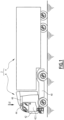
- Figure 1 represents, in side view, a vehicle which is, in the example, a truck 2.
- the vehicle may be different from a truck.
- the vehicle may be a light-duty vehicle, a utility vehicle, an autonomous vehicle, etc.
- the truck 2 includes a towing vehicle 4 and a trailer 6.
- Towing vehicle 4 has a lower frame 40, a cabin 42 with cabin doors 42.1 and a cabin roof 46.
- the truck is equipped with side cameras 44 replacing the outside mirrors of a conventional truck. In the example, the side cameras 44 are arranged above the cabin doors 42.1.
- the side cameras 44 are foldable.
- the side cameras 44 are movable between a first position (unfolded position), represented on figure 2 , wherein the side cameras 44 extend substantially in a perpendicular direction relative to the truck cabin and a second position (folded position), represented on figure 3 , wherein the side cameras 44 are folded against the cabin wall.
- the truck includes an actuator (not represented) for unfolding the side cameras 44 when the vehicle is started and for folding the cameras 44 when the vehicle is parked. Then, each camera 44 is in the first position when the vehicle is moving and in the second position when the vehicle is parked.
- Said actuator is known from prior art, that is why it is not described in detail.
- the truck 2 may be considered as being parked when at least one of the following conditions is fulfilled:
- truck 2 may be considered as being started when at least one of the following conditions is fulfilled:
- Each side camera 44 includes a fixed part 44b attached to the truck cabin and a movable part 44a that is articulated on the fixed part 44b.
- the movable part 44a includes a camera lens 44c for recording, in real time, images on one side of the truck 2 (See detection cones on figure 2 ).
- the camera lens 44c is arranged at the free end of the movable part 44a.
- At least one, preferably two screens may be arranged inside the cabin to display the images recorded by the two side cameras 44.
- the side cameras 44 have to remain clean in order to provide reliable information.
- the vehicle 2 is equipped with a washing system 3 for each camera 44.
- truck 2 is then equipped with two washing systems 3 that are preferably arranged inside the truck cabin 42, above the cabin doors 42.1.
- Each washing system 3 includes a housing 10 for receiving the camera 44, and in particular for receiving the camera lens 44c of the camera.
- the camera lens 44c is received inside the housing 10 when the camera 44 is in second position (folded position), i.e. when the vehicle is parked.
- the driver may have the possibility of cleaning the cameras 44, i.e. folding the cameras 44, for example when the vehicle is stopped at a red light.
- specific activation means may be provided inside the cabin.
- Each washing system 3 also includes a cleaning fluid storage tank 20, a nozzle 12 for spraying the cleaning fluid, inside the housing 10, onto the camera lens 44c and a pump 22 for pumping the cleaning fluid from the tank 20 to the nozzle 12.
- the housing 10 has a rectangular section and includes a bottom wall 10.1, a front wall 10.2 and two side walls.
- the two side walls are perpendicular to the cabin wall, while the front wall 10.2 is parallel to the cabin wall.
- 10.3 denotes the side wall of the housing 10 (among the two side walls) that is the closest one from the camera 44.
- the nozzle 12 is a hole arranged in one of the side walls of the housing 10, in particular in the side wall 10.3.
- This hole is oriented so as to spray cleaning liquid along a direction that is substantially perpendicular to the side wall 10.3. Accordingly, the spray of cleaning liquid is inclined or parallel to the surface of the camera lens, i.e. not perpendicular to the surface of the camera lens 44c. Thanks to this configuration, the spray of cleaning liquid removes effectively the dust gathered on the camera lens surface.
- the washing system 3 includes a passage 18 for draining used cleaning fluid back into the tank 20. Accordingly, the passage 18 extends vertically.
- the passage 18 has a first end 16 opening on the inside of the housing 10 and a second end opening on the inside of the tank 20.
- the first end 16 is a top end, while the second end is a bottom end.
- the first end 16 is formed by a hole in the bottom wall 10.1 of the housing 10.
- the tank 20 is then arranged below the housing 10, so that used cleaning fluid may be drained under gravity back into the tank 20. In other words, there is no need for an additional pump (and energy) to convey the used cleaning fluid from the housing 10 to the tank 20.
- the hole 16 is arranged in a collector 14 forming a recess in the bottom wall 10.1 of the housing 10.
- the housing 10 is directly attached to the tank 20.
- the tank 20 is not remote from the housing 10.
- this is different from the system of KR 2007 002 299 8 wherein the collector of used liquid is remote from the container located under the hood of the vehicle.
- a non-return valve (not represented) is housed in the passage 18. This non-return valve prevents the cleaning fluid stored into the tank 20 from flowing into the housing 10 through passage 18.
- Such non-return valve is known from prior art, that is why it is not described in detail.
- the front wall 10.2 of the housing 10 is a movable trap for the passage of the camera 44.
- this trap is articulated towards the inside of the housing 10.
- the movable trap is flush with the exterior of the cabin 42 when it is closed, so that the washing system 3 does not increase the wind resistance of the vehicle in driving conditions.
- the washing system further includes a filter (not represented) between the tank 20 and the pump 22.
- This filter allows filtering out dirt so as to avoid clogging the pump 22.
- This filter may be removable, so that it can be easily cleaned or replaced.
- the side cameras 44 move from their first position to their second position. Each side camera 44 pushes the movable trap 10.1 of the housing 10 so that the camera lens may enter into the housing 10. Then, cleaning liquid is sprayed onto the camera lens 44c. Used cleaning liquid flows, under gravity, through the hole 16 and the passage 18, and is recuperated into the tank 20.
- the side cameras 44 move back in their first position.
- the movable trap 10.1 moves back into a closed position under gravity.
- Figure 7 represents a washing system for a vehicle according to a second embodiment of the invention. For the purpose of conciseness, only the differences relative to the first embodiment are mentioned here-after.
- the camera lens 44c is enclosed in the housing 10' when the camera is in the second position.
- the housing 10' is shaped so as to form a closed volume V10 when the camera 44 is in second position (folded position). Thanks to this configuration, the camera lens 44c does not gather external dust when the vehicle is parked, in particular when the vehicle is parked for a long time. Accordingly, the cleaning frequency is less important.
- the housing 10' remains open in driving conditions.
- the housing 10' has a semi-circular section.
- the housing 10 is integral with the tank 20.
- the camera is a rearview camera.
- a locking mechanism can be added to prevent camera theft.
- This locking mechanism could be a pin that prevents manual unfolding.
Landscapes
- Engineering & Computer Science (AREA)
- Mechanical Engineering (AREA)
- Water Supply & Treatment (AREA)
- Multimedia (AREA)
- Signal Processing (AREA)
- Studio Devices (AREA)
Description
- The present invention concerns a vehicle comprising at least one camera and one corresponding washing system for cleaning the camera. In particular, the invention relates to a vehicle, such as a truck, comprising side cameras replacing outside mirrors and an autonomous washing system for each camera. The invention could also apply to the rearview camera of a vehicle.
- In the automotive industry, the trend is to equip the vehicles with onboard cameras for replacing the traditional outside mirrors. Indeed, a camera has significantly less windage than an outside mirror and helps then improving the aerodynamic behavior of the vehicle. Further, infrared cameras provide the driver with an enhanced vision in dark surroundings. Also, cameras are being used increasingly in the blind spot information systems, in the back-up assist systems of the vehicles and in the autonomous vehicles. However, given the importance of such functions, the cameras must provide reliable information.
- To this end, the cameras should be cleaned regularly. For example, the cameras may be cleaned manually by the driver using a dry or damp cloth. However, there is a risk that the driver forgets to clean the camera. Also, the camera lens can be difficult to reach. For example, the side cameras replacing the outside mirrors of a truck are very high relative to the ground and are not accessible without special equipment (step ladder). Therefore, there exist automatic washing systems for cleaning the camera lens on a regular basis. These systems include a cleaning fluid container, at least one nozzle for pulverizing the cleaning fluid onto the lens and a pump for pumping the cleaning fluid from the container to the nozzle.
- In the case of a truck comprising side cameras replacing outside mirrors, the cleaning fluid container is arranged on the lower frame, i.e. at the height of the wheels. Therefore, there is at least one pipe extending from the container arranged on the frame to the nozzles arranged at an upper part of the cabin where are located the side cameras. This pipe is routed inside the cabin, sometimes near electrical cables. Accordingly, any leak may have major consequences.
- In addition, the side cameras of a truck are located above the two cabin doors. Therefore, when the cameras lenses are cleaned, cleaning fluid may drop on the sides of the truck, and in particular on the driver entering the cabin and/or on a person passing by the truck. This is obviously not desirable. Also, the cleaning fluid is not collected, so that the container has to be refilled quite often.
-
WO 2009/101044 A2 discloses a vehicle according to the preamble of claim 1. -
KR 2007 0022998 - The aim of the present invention is to propose a vehicle that remedies the abovementioned drawbacks.
- To this end, the invention concerns a vehicle, comprising at least one camera and one corresponding washing system for cleaning the camera, the washing system comprising a housing for receiving the camera, a cleaning fluid storage tank, a nozzle for spraying the cleaning fluid inside the housing and a pump for pumping the cleaning fluid from the tank to the nozzle. According to the invention, the washing system further includes a passage extending from the housing to the tank, for draining, under gravity, used cleaning fluid back into the tank. Additionally, according to the invention, the housing is directly attached to the tank or integral with the tank and each camera is in a first position when the vehicle is moving and in a second position, different from the first position, when the vehicle is parked.
- Thanks to the invention, the cleaning fluid is recycled and there is no need to control the level of liquid inside the tank and to refill the tank, since the level of liquid inside the tank is always the same. Further, there is no evacuation of the cleaning fluid outside the truck, and then no risk of splashing the driver entering the cabin or a person passing by the vehicle. Advantageously, after a certain period of use, the tank is emptied and refilled with new cleaning fluid.
- According to further advantageous features of the vehicle according to the invention, taken in isolation or in combination:
- A non-return valve is housed in the passage.
- The housing includes a movable trap for the passage of the camera.
- The movable trap is flush with the exterior of the cabin when it is closed.
- The washing system further includes a filter between the tank and the pump.
- Each camera includes a camera lens that is enclosed in the housing when the camera is in the second position.
- Each camera is foldable between the first position and the second position.
- The vehicle is a truck including two side cameras replacing outside mirrors and two corresponding washing systems that are arranged inside the truck cabin, above the cabin doors.
- The invention will be better understood from reading the following description, given solely by way of two non-limiting examples and with reference to the appended drawings, which are schematic depictions, in which:
-
figure 1 is a side view of a vehicle, in particular a truck, according to a first embodiment of the invention, such vehicle including two side cameras replacing outside mirrors and two corresponding washing systems for cleaning the side cameras; -
figure 2 is a partial view of the truck in the direction of arrow II infigure 1 (top view); -
figure 3 is an illustration analog tofigure 2 , representing the side cameras in a folded position; -
figures 4 and 5 are partial side views, respectively according to arrows IV and V onfigures 2 and 3 ; -
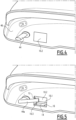
figure 6 is an inside and partial view of the truck cabin offigure 1 ; and -
figure 7 represents, in top view, a washing system of a vehicle according to a second embodiment of the invention. -
Figure 1 represents, in side view, a vehicle which is, in the example, atruck 2. However, in a non-represented alternative embodiment, the vehicle may be different from a truck. For instance, the vehicle may a light-duty vehicle, a utility vehicle, an autonomous vehicle, etc. - The
truck 2 includes atowing vehicle 4 and atrailer 6.Towing vehicle 4 has alower frame 40, acabin 42 with cabin doors 42.1 and acabin roof 46. The truck is equipped withside cameras 44 replacing the outside mirrors of a conventional truck. In the example, theside cameras 44 are arranged above the cabin doors 42.1. - As shown on
figures 2 and 3 , theside cameras 44 are foldable. In particular, theside cameras 44 are movable between a first position (unfolded position), represented onfigure 2 , wherein theside cameras 44 extend substantially in a perpendicular direction relative to the truck cabin and a second position (folded position), represented onfigure 3 , wherein theside cameras 44 are folded against the cabin wall. - Advantageously, the truck includes an actuator (not represented) for unfolding the
side cameras 44 when the vehicle is started and for folding thecameras 44 when the vehicle is parked. Then, eachcamera 44 is in the first position when the vehicle is moving and in the second position when the vehicle is parked. Said actuator is known from prior art, that is why it is not described in detail. - In the example, the
truck 2 may be considered as being parked when at least one of the following conditions is fulfilled: - the driver leaves the cabin;
- the engine is turned off;
- the parking brake is engaged.
- Conversely, the
truck 2 may be considered as being started when at least one of the following conditions is fulfilled: - the engine is turned on;
- the parking brake is released;
- the driver depresses the throttle;
- a gearbox ratio is engaged;
- the driver depresses the pedal brake.
- Each
side camera 44 includes afixed part 44b attached to the truck cabin and amovable part 44a that is articulated on thefixed part 44b. Themovable part 44a includes acamera lens 44c for recording, in real time, images on one side of the truck 2 (See detection cones onfigure 2 ). Preferably, thecamera lens 44c is arranged at the free end of themovable part 44a. - Advantageously, at least one, preferably two screens (not represented) may be arranged inside the cabin to display the images recorded by the two
side cameras 44. - The
side cameras 44 have to remain clean in order to provide reliable information. To this end, thevehicle 2 is equipped with awashing system 3 for eachcamera 44. In the example,truck 2 is then equipped with twowashing systems 3 that are preferably arranged inside thetruck cabin 42, above the cabin doors 42.1. - Each
washing system 3 includes ahousing 10 for receiving thecamera 44, and in particular for receiving thecamera lens 44c of the camera. In particular, thecamera lens 44c is received inside thehousing 10 when thecamera 44 is in second position (folded position), i.e. when the vehicle is parked. Alternatively, the driver may have the possibility of cleaning thecameras 44, i.e. folding thecameras 44, for example when the vehicle is stopped at a red light. To this end, specific activation means may be provided inside the cabin. - Each
washing system 3 also includes a cleaningfluid storage tank 20, anozzle 12 for spraying the cleaning fluid, inside thehousing 10, onto thecamera lens 44c and apump 22 for pumping the cleaning fluid from thetank 20 to thenozzle 12. - In the example, the
housing 10 has a rectangular section and includes a bottom wall 10.1, a front wall 10.2 and two side walls. The two side walls are perpendicular to the cabin wall, while the front wall 10.2 is parallel to the cabin wall. 10.3 denotes the side wall of the housing 10 (among the two side walls) that is the closest one from thecamera 44. - Advantageously, the
nozzle 12 is a hole arranged in one of the side walls of thehousing 10, in particular in the side wall 10.3. This hole is oriented so as to spray cleaning liquid along a direction that is substantially perpendicular to the side wall 10.3. Accordingly, the spray of cleaning liquid is inclined or parallel to the surface of the camera lens, i.e. not perpendicular to the surface of thecamera lens 44c. Thanks to this configuration, the spray of cleaning liquid removes effectively the dust gathered on the camera lens surface. - The
washing system 3 includes apassage 18 for draining used cleaning fluid back into thetank 20. Accordingly, thepassage 18 extends vertically. Thepassage 18 has afirst end 16 opening on the inside of thehousing 10 and a second end opening on the inside of thetank 20. Thefirst end 16 is a top end, while the second end is a bottom end. Thefirst end 16 is formed by a hole in the bottom wall 10.1 of thehousing 10. Thetank 20 is then arranged below thehousing 10, so that used cleaning fluid may be drained under gravity back into thetank 20. In other words, there is no need for an additional pump (and energy) to convey the used cleaning fluid from thehousing 10 to thetank 20. - Preferably, and as shown on
figure 5 , thehole 16 is arranged in acollector 14 forming a recess in the bottom wall 10.1 of thehousing 10. - Advantageously, the
housing 10 is directly attached to thetank 20. This means that thetank 20 is not remote from thehousing 10. In particular, this is different from the system ofKR 2007 002 299 8 - Optionally, a non-return valve (not represented) is housed in the
passage 18. This non-return valve prevents the cleaning fluid stored into thetank 20 from flowing into thehousing 10 throughpassage 18. Such non-return valve is known from prior art, that is why it is not described in detail. - In the example, the front wall 10.2 of the
housing 10 is a movable trap for the passage of thecamera 44. In the example, this trap is articulated towards the inside of thehousing 10. The movable trap is flush with the exterior of thecabin 42 when it is closed, so that thewashing system 3 does not increase the wind resistance of the vehicle in driving conditions. - Optionally, the washing system further includes a filter (not represented) between the
tank 20 and thepump 22. This filter allows filtering out dirt so as to avoid clogging thepump 22. This filter may be removable, so that it can be easily cleaned or replaced. - When the
vehicle 2 is parked, for example when the engine is turned off, theside cameras 44 move from their first position to their second position. Eachside camera 44 pushes the movable trap 10.1 of thehousing 10 so that the camera lens may enter into thehousing 10. Then, cleaning liquid is sprayed onto thecamera lens 44c. Used cleaning liquid flows, under gravity, through thehole 16 and thepassage 18, and is recuperated into thetank 20. - When the vehicle drives off, for example when the engine is started, the
side cameras 44 move back in their first position. The movable trap 10.1 moves back into a closed position under gravity. -
Figure 7 represents a washing system for a vehicle according to a second embodiment of the invention. For the purpose of conciseness, only the differences relative to the first embodiment are mentioned here-after. - In the second embodiment, the
camera lens 44c is enclosed in the housing 10' when the camera is in the second position. This means that the housing 10' is shaped so as to form a closed volume V10 when thecamera 44 is in second position (folded position). Thanks to this configuration, thecamera lens 44c does not gather external dust when the vehicle is parked, in particular when the vehicle is parked for a long time. Accordingly, the cleaning frequency is less important. - Preferably, there is no movable trap: the housing 10' remains open in driving conditions. In the example, the housing 10' has a semi-circular section.
- In a non-represented alternative embodiment, the
housing 10 is integral with thetank 20. - In another non-represented alternative embodiment, the camera is a rearview camera.
- In another non-represented alternative embodiment, a locking mechanism can be added to prevent camera theft. This locking mechanism could be a pin that prevents manual unfolding.
- The features of the two described embodiments and of non-represented alternative embodiments may be combined together in order to generate new embodiments of the invention.
Claims (8)
- Vehicle (2), comprising at least one camera (44) and one corresponding washing system (3) for cleaning the camera, the washing system comprising:- a housing (10) for receiving the camera,- a cleaning fluid storage tank (20),- a nozzle (12) for spraying the cleaning fluid inside the housing,- a pump (22) for pumping the cleaning fluid from the tank to the nozzle, wherein each camera (44) is in a first position when the vehicle is moving and in a second position, different from the first position, when the vehicle is parked, characterized in that the washing system further includes a passage (18) extending from the housing (10) to the tank (20), for draining, under gravity, used cleaning fluid back into the tank (20) and in that the housing (10) is directly attached to the tank (20) or integral with the tank.
- Vehicle according to claim 1, characterized in that a non-return valve is housed in the passage (18).
- Vehicle according to any previous claim, characterized in that the housing (10) includes a movable trap (10.2) for the passage of the camera (44).
- Vehicle according to claim 3, characterized in that the movable trap (10.2) is flush with the exterior of the cabin when it is closed.
- Vehicle according to any previous claim, characterized in that the washing system (3) further includes a filter between the tank (20) and the pump (22).
- Vehicle according to any previous claim, characterized in that each camera (44) includes a camera lens (44c) that is enclosed in the housing (10) when the camera is in the second position.
- Vehicle according to any previous claim, characterized in that each camera (44) is foldable between the first position and the second position.
- Vehicle according to any previous claim, characterized in that the vehicle is a truck including two side cameras (44) replacing outside mirrors and two corresponding washing systems (3) that are arranged inside the truck cabin (42), above the cabin doors (42.1).
Applications Claiming Priority (1)
| Application Number | Priority Date | Filing Date | Title |
|---|---|---|---|
| PCT/IB2017/000798 WO2018206997A1 (en) | 2017-05-10 | 2017-05-10 | Vehicle comprising at least one camera and one corresponding washing system for cleaning the camera |
Publications (3)
| Publication Number | Publication Date |
|---|---|
| EP3621856A1 EP3621856A1 (en) | 2020-03-18 |
| EP3621856C0 EP3621856C0 (en) | 2023-06-07 |
| EP3621856B1 true EP3621856B1 (en) | 2023-06-07 |
Family
ID=59350986
Family Applications (1)
| Application Number | Title | Priority Date | Filing Date |
|---|---|---|---|
| EP17740080.1A Active EP3621856B1 (en) | 2017-05-10 | 2017-05-10 | Vehicle comprising at least one camera and one corresponding washing system for cleaning the camera |
Country Status (4)
| Country | Link |
|---|---|
| US (1) | US11130475B2 (en) |
| EP (1) | EP3621856B1 (en) |
| CN (1) | CN110461661A (en) |
| WO (1) | WO2018206997A1 (en) |
Cited By (1)
| Publication number | Priority date | Publication date | Assignee | Title |
|---|---|---|---|---|
| DE102025108835B3 (en) * | 2025-03-10 | 2026-02-12 | Dr. Ing. H.C. F. Porsche Aktiengesellschaft | motor vehicle |
Families Citing this family (7)
| Publication number | Priority date | Publication date | Assignee | Title |
|---|---|---|---|---|
| DE102019122202B4 (en) | 2019-08-19 | 2023-06-07 | Webasto SE | Roof module with environment sensor for autonomous or semi-autonomous driving |
| DE102019216122A1 (en) * | 2019-10-21 | 2021-04-22 | Zf Friedrichshafen Ag | Method for cleaning a sensor unit and cleaning device |
| DE102020119473A1 (en) | 2020-07-23 | 2022-01-27 | Zf Cv Systems Global Gmbh | Sensor cleaning system, vehicle |
| CN111921931B (en) * | 2020-07-31 | 2021-10-29 | 广州纯元科技有限公司 | Intelligent security equipment with snow removing function |
| DE102021115335B4 (en) | 2021-06-14 | 2023-10-05 | Webasto SE | Roof module for forming a vehicle roof with a cleaning device |
| DE102021115340B4 (en) | 2021-06-14 | 2023-10-05 | Webasto SE | Roof module for forming a vehicle roof with a cleaning device |
| JP2023102607A (en) * | 2022-01-12 | 2023-07-25 | 株式会社東海理化電機製作所 | Visual recognition device for vehicle |
Citations (2)
| Publication number | Priority date | Publication date | Assignee | Title |
|---|---|---|---|---|
| DE102008008656A1 (en) * | 2008-02-11 | 2009-08-13 | Huf Hülsbeck & Fürst Gmbh & Co. Kg | Camera system for a motor vehicle with a camera unit |
| US20120117745A1 (en) * | 2009-09-29 | 2012-05-17 | Denso Corporation | On-board optical sensor cover and on-board optical sensor apparatus |
Family Cites Families (15)
| Publication number | Priority date | Publication date | Assignee | Title |
|---|---|---|---|---|
| GB2357240B (en) * | 1999-12-15 | 2003-12-17 | Gary Michael Thompson | Bin cleaning apparatus |
| AU2003290791A1 (en) * | 2002-11-14 | 2004-06-15 | Donnelly Corporation | Imaging system for vehicle |
| KR20070022998A (en) | 2005-08-23 | 2007-02-28 | 주식회사 현대오토넷 | Recycling device of vehicle washer liquid |
| WO2008012801A2 (en) * | 2006-07-24 | 2008-01-31 | Microheat Inc. | Vehicle surfaces cleaning and de-icing system and method |
| US20110292212A1 (en) * | 2010-05-27 | 2011-12-01 | Asmo Co., Ltd. | Washer nozzle for vehicle mounted camera, vehicle mounted camera, and washer device for vehicle |
| JP5803831B2 (en) * | 2012-07-23 | 2015-11-04 | 株式会社デンソー | In-vehicle optical sensor cleaning device |
| EP3105089B1 (en) * | 2014-02-14 | 2018-03-14 | Kautex Textron GmbH & Co. KG. | Air and fluid cleaning system and method for cleaning vehicle vision devices |
| US10059280B2 (en) * | 2014-06-06 | 2018-08-28 | Joseph Richard Cooper | Obstruction-removal system and method for vehicle-camera lens |
| DE102014010495B3 (en) * | 2014-07-16 | 2015-12-17 | Kautex Textron Gmbh & Co. Kg | Vehicle integrated vision and cleaning system |
| CN204035099U (en) * | 2014-08-08 | 2014-12-24 | 开封中达汽车饰件有限公司 | A kind of fascia cleaning room |
| US10442405B2 (en) * | 2014-11-10 | 2019-10-15 | Brimtech, Llc | Processing captured vehicle fluid |
| DE102015117612A1 (en) * | 2015-10-16 | 2017-04-20 | Connaught Electronics Ltd. | Camera holding device for a camera of a motor vehicle, camera arrangement and motor vehicle |
| DE102015118670A1 (en) * | 2015-10-30 | 2017-05-04 | Huf Hülsbeck & Fürst Gmbh & Co. Kg | Camera device for a motor vehicle |
| FR3051753B1 (en) | 2016-05-27 | 2018-06-15 | Valeo Systemes D'essuyage | SYSTEM FOR CLEANING AN OPTICAL SENSOR, AN ASSEMBLY COMPRISING SUCH A SYSTEM AND AN ASSOCIATED MOTOR VEHICLE |
| US20180312141A1 (en) * | 2017-04-27 | 2018-11-01 | Ford Global Technologies, Llc | Methods and apparatus for application of washer fluid to vehicle cameras |
-
2017
- 2017-05-10 WO PCT/IB2017/000798 patent/WO2018206997A1/en not_active Ceased
- 2017-05-10 US US16/490,096 patent/US11130475B2/en active Active
- 2017-05-10 CN CN201780087737.3A patent/CN110461661A/en active Pending
- 2017-05-10 EP EP17740080.1A patent/EP3621856B1/en active Active
Patent Citations (2)
| Publication number | Priority date | Publication date | Assignee | Title |
|---|---|---|---|---|
| DE102008008656A1 (en) * | 2008-02-11 | 2009-08-13 | Huf Hülsbeck & Fürst Gmbh & Co. Kg | Camera system for a motor vehicle with a camera unit |
| US20120117745A1 (en) * | 2009-09-29 | 2012-05-17 | Denso Corporation | On-board optical sensor cover and on-board optical sensor apparatus |
Cited By (1)
| Publication number | Priority date | Publication date | Assignee | Title |
|---|---|---|---|---|
| DE102025108835B3 (en) * | 2025-03-10 | 2026-02-12 | Dr. Ing. H.C. F. Porsche Aktiengesellschaft | motor vehicle |
Also Published As
| Publication number | Publication date |
|---|---|
| WO2018206997A1 (en) | 2018-11-15 |
| US11130475B2 (en) | 2021-09-28 |
| EP3621856A1 (en) | 2020-03-18 |
| EP3621856C0 (en) | 2023-06-07 |
| US20200010055A1 (en) | 2020-01-09 |
| CN110461661A (en) | 2019-11-15 |
Similar Documents
| Publication | Publication Date | Title |
|---|---|---|
| EP3621856B1 (en) | Vehicle comprising at least one camera and one corresponding washing system for cleaning the camera | |
| EP3665045B1 (en) | Vehicle camera system comprising an integrated lens cleaning mechanism, vehicle comprising such camera system and method | |
| US20210237694A1 (en) | Roof module for forming a vehicle roof | |
| KR102320163B1 (en) | Camera for vehicle and window washing system thereof | |
| CN106536296B (en) | The integrated on-vehicle vehicle visual field and cleaning systems | |
| CN114258362B (en) | Roof module with environmental sensors for autonomous or partially autonomous vehicle operation | |
| CN109835306A (en) | Vehicle Sensor Cleaning | |
| US11377073B2 (en) | System for cleaning an optical sensor, assembly comprising such a system, and associated motor vehicle | |
| NO20170980A1 (en) | Cleaning assembly for cleaning surface of vehicle-mounted camera or sensor | |
| WO2016045828A1 (en) | Device for protection of an optical sensor | |
| EP3224093A1 (en) | Integrated on-board vehicle vision and cleaning system | |
| JP2014201150A (en) | On-vehicle imaging device, dirt preventing method of optical member, and camera module | |
| FR3027006A1 (en) | DEVICE FOR PROTECTING AN OPTICAL SENSOR | |
| KR102312411B1 (en) | Apparatus Cleaning Dust of Moving Camera Lens | |
| US20060090776A1 (en) | Method for washing a vehicle | |
| CN211685004U (en) | Vehicle-mounted camera cleaning device and integrated vehicle-mounted cleaning system | |
| US20240425017A1 (en) | Sensor cleaning with improved cleaning liquid collection | |
| DE102010005311A1 (en) | Camera arrangement for monitoring area behind rear of vehicle, has immovable camera inserted in rear of vehicle, particularly in rear flap | |
| US11519145B2 (en) | Utility vehicle to remove matter from surface | |
| CN213109202U (en) | Sensor device and vehicle | |
| CN108146346A (en) | A kind of forward sight auxiliary system and its control method | |
| US9994088B2 (en) | Wiper assembly for a windshield of a vehicle | |
| CN211726709U (en) | Vehicle-mounted camera cleaning device | |
| FR3143502A1 (en) | Device for dispensing cleaning fluid for the windshield of a motor vehicle, and motor vehicle comprising such a device | |
| FR3141121A1 (en) | Device for dispensing cleaning fluid for the windshield of a motor vehicle, and motor vehicle comprising such a device |
Legal Events
| Date | Code | Title | Description |
|---|---|---|---|
| STAA | Information on the status of an ep patent application or granted ep patent |
Free format text: STATUS: UNKNOWN |
|
| STAA | Information on the status of an ep patent application or granted ep patent |
Free format text: STATUS: THE INTERNATIONAL PUBLICATION HAS BEEN MADE |
|
| PUAI | Public reference made under article 153(3) epc to a published international application that has entered the european phase |
Free format text: ORIGINAL CODE: 0009012 |
|
| STAA | Information on the status of an ep patent application or granted ep patent |
Free format text: STATUS: REQUEST FOR EXAMINATION WAS MADE |
|
| 17P | Request for examination filed |
Effective date: 20191127 |
|
| AK | Designated contracting states |
Kind code of ref document: A1 Designated state(s): AL AT BE BG CH CY CZ DE DK EE ES FI FR GB GR HR HU IE IS IT LI LT LU LV MC MK MT NL NO PL PT RO RS SE SI SK SM TR |
|
| AX | Request for extension of the european patent |
Extension state: BA ME |
|
| DAV | Request for validation of the european patent (deleted) | ||
| DAX | Request for extension of the european patent (deleted) | ||
| STAA | Information on the status of an ep patent application or granted ep patent |
Free format text: STATUS: EXAMINATION IS IN PROGRESS |
|
| 17Q | First examination report despatched |
Effective date: 20201124 |
|
| GRAP | Despatch of communication of intention to grant a patent |
Free format text: ORIGINAL CODE: EPIDOSNIGR1 |
|
| STAA | Information on the status of an ep patent application or granted ep patent |
Free format text: STATUS: GRANT OF PATENT IS INTENDED |
|
| INTG | Intention to grant announced |
Effective date: 20221207 |
|
| GRAS | Grant fee paid |
Free format text: ORIGINAL CODE: EPIDOSNIGR3 |
|
| GRAA | (expected) grant |
Free format text: ORIGINAL CODE: 0009210 |
|
| STAA | Information on the status of an ep patent application or granted ep patent |
Free format text: STATUS: THE PATENT HAS BEEN GRANTED |
|
| AK | Designated contracting states |
Kind code of ref document: B1 Designated state(s): AL AT BE BG CH CY CZ DE DK EE ES FI FR GB GR HR HU IE IS IT LI LT LU LV MC MK MT NL NO PL PT RO RS SE SI SK SM TR |
|
| REG | Reference to a national code |
Ref country code: GB Ref legal event code: FG4D |
|
| REG | Reference to a national code |
Ref country code: CH Ref legal event code: EP Ref country code: AT Ref legal event code: REF Ref document number: 1574087 Country of ref document: AT Kind code of ref document: T Effective date: 20230615 |
|
| REG | Reference to a national code |
Ref country code: DE Ref legal event code: R096 Ref document number: 602017069566 Country of ref document: DE |
|
| U01 | Request for unitary effect filed |
Effective date: 20230623 |
|
| U07 | Unitary effect registered |
Designated state(s): AT BE BG DE DK EE FI FR IT LT LU LV MT NL PT SE SI Effective date: 20230629 |
|
| REG | Reference to a national code |
Ref country code: LT Ref legal event code: MG9D |
|
| PG25 | Lapsed in a contracting state [announced via postgrant information from national office to epo] |
Ref country code: NO Free format text: LAPSE BECAUSE OF FAILURE TO SUBMIT A TRANSLATION OF THE DESCRIPTION OR TO PAY THE FEE WITHIN THE PRESCRIBED TIME-LIMIT Effective date: 20230907 Ref country code: ES Free format text: LAPSE BECAUSE OF FAILURE TO SUBMIT A TRANSLATION OF THE DESCRIPTION OR TO PAY THE FEE WITHIN THE PRESCRIBED TIME-LIMIT Effective date: 20230607 |
|
| PG25 | Lapsed in a contracting state [announced via postgrant information from national office to epo] |
Ref country code: RS Free format text: LAPSE BECAUSE OF FAILURE TO SUBMIT A TRANSLATION OF THE DESCRIPTION OR TO PAY THE FEE WITHIN THE PRESCRIBED TIME-LIMIT Effective date: 20230607 Ref country code: HR Free format text: LAPSE BECAUSE OF FAILURE TO SUBMIT A TRANSLATION OF THE DESCRIPTION OR TO PAY THE FEE WITHIN THE PRESCRIBED TIME-LIMIT Effective date: 20230607 Ref country code: GR Free format text: LAPSE BECAUSE OF FAILURE TO SUBMIT A TRANSLATION OF THE DESCRIPTION OR TO PAY THE FEE WITHIN THE PRESCRIBED TIME-LIMIT Effective date: 20230908 |
|
| PG25 | Lapsed in a contracting state [announced via postgrant information from national office to epo] |
Ref country code: SK Free format text: LAPSE BECAUSE OF FAILURE TO SUBMIT A TRANSLATION OF THE DESCRIPTION OR TO PAY THE FEE WITHIN THE PRESCRIBED TIME-LIMIT Effective date: 20230607 |
|
| PG25 | Lapsed in a contracting state [announced via postgrant information from national office to epo] |
Ref country code: IS Free format text: LAPSE BECAUSE OF FAILURE TO SUBMIT A TRANSLATION OF THE DESCRIPTION OR TO PAY THE FEE WITHIN THE PRESCRIBED TIME-LIMIT Effective date: 20231007 |
|
| PG25 | Lapsed in a contracting state [announced via postgrant information from national office to epo] |
Ref country code: SM Free format text: LAPSE BECAUSE OF FAILURE TO SUBMIT A TRANSLATION OF THE DESCRIPTION OR TO PAY THE FEE WITHIN THE PRESCRIBED TIME-LIMIT Effective date: 20230607 Ref country code: SK Free format text: LAPSE BECAUSE OF FAILURE TO SUBMIT A TRANSLATION OF THE DESCRIPTION OR TO PAY THE FEE WITHIN THE PRESCRIBED TIME-LIMIT Effective date: 20230607 Ref country code: RO Free format text: LAPSE BECAUSE OF FAILURE TO SUBMIT A TRANSLATION OF THE DESCRIPTION OR TO PAY THE FEE WITHIN THE PRESCRIBED TIME-LIMIT Effective date: 20230607 Ref country code: IS Free format text: LAPSE BECAUSE OF FAILURE TO SUBMIT A TRANSLATION OF THE DESCRIPTION OR TO PAY THE FEE WITHIN THE PRESCRIBED TIME-LIMIT Effective date: 20231007 Ref country code: CZ Free format text: LAPSE BECAUSE OF FAILURE TO SUBMIT A TRANSLATION OF THE DESCRIPTION OR TO PAY THE FEE WITHIN THE PRESCRIBED TIME-LIMIT Effective date: 20230607 |
|
| PG25 | Lapsed in a contracting state [announced via postgrant information from national office to epo] |
Ref country code: PL Free format text: LAPSE BECAUSE OF FAILURE TO SUBMIT A TRANSLATION OF THE DESCRIPTION OR TO PAY THE FEE WITHIN THE PRESCRIBED TIME-LIMIT Effective date: 20230607 |
|
| REG | Reference to a national code |
Ref country code: DE Ref legal event code: R097 Ref document number: 602017069566 Country of ref document: DE |
|
| PLBE | No opposition filed within time limit |
Free format text: ORIGINAL CODE: 0009261 |
|
| STAA | Information on the status of an ep patent application or granted ep patent |
Free format text: STATUS: NO OPPOSITION FILED WITHIN TIME LIMIT |
|
| 26N | No opposition filed |
Effective date: 20240308 |
|
| U20 | Renewal fee for the european patent with unitary effect paid |
Year of fee payment: 8 Effective date: 20240527 |
|
| REG | Reference to a national code |
Ref country code: CH Ref legal event code: PL |
|
| PG25 | Lapsed in a contracting state [announced via postgrant information from national office to epo] |
Ref country code: MC Free format text: LAPSE BECAUSE OF FAILURE TO SUBMIT A TRANSLATION OF THE DESCRIPTION OR TO PAY THE FEE WITHIN THE PRESCRIBED TIME-LIMIT Effective date: 20230607 |
|
| GBPC | Gb: european patent ceased through non-payment of renewal fee |
Effective date: 20240510 |
|
| PG25 | Lapsed in a contracting state [announced via postgrant information from national office to epo] |
Ref country code: MC Free format text: LAPSE BECAUSE OF FAILURE TO SUBMIT A TRANSLATION OF THE DESCRIPTION OR TO PAY THE FEE WITHIN THE PRESCRIBED TIME-LIMIT Effective date: 20230607 Ref country code: CH Free format text: LAPSE BECAUSE OF NON-PAYMENT OF DUE FEES Effective date: 20240531 |
|
| PG25 | Lapsed in a contracting state [announced via postgrant information from national office to epo] |
Ref country code: IE Free format text: LAPSE BECAUSE OF NON-PAYMENT OF DUE FEES Effective date: 20240510 |
|
| PG25 | Lapsed in a contracting state [announced via postgrant information from national office to epo] |
Ref country code: GB Free format text: LAPSE BECAUSE OF NON-PAYMENT OF DUE FEES Effective date: 20240510 |
|
| U20 | Renewal fee for the european patent with unitary effect paid |
Year of fee payment: 9 Effective date: 20250526 |
|
| PG25 | Lapsed in a contracting state [announced via postgrant information from national office to epo] |
Ref country code: CY Free format text: LAPSE BECAUSE OF FAILURE TO SUBMIT A TRANSLATION OF THE DESCRIPTION OR TO PAY THE FEE WITHIN THE PRESCRIBED TIME-LIMIT; INVALID AB INITIO Effective date: 20170510 |
|
| PG25 | Lapsed in a contracting state [announced via postgrant information from national office to epo] |
Ref country code: HU Free format text: LAPSE BECAUSE OF FAILURE TO SUBMIT A TRANSLATION OF THE DESCRIPTION OR TO PAY THE FEE WITHIN THE PRESCRIBED TIME-LIMIT; INVALID AB INITIO Effective date: 20170510 |