EP3621783B1 - Verfahren zur herstellung eines dreidimensionalen objektes mittels einer generativen fertigungstechnologie - Google Patents
Verfahren zur herstellung eines dreidimensionalen objektes mittels einer generativen fertigungstechnologie Download PDFInfo
- Publication number
- EP3621783B1 EP3621783B1 EP18721424.2A EP18721424A EP3621783B1 EP 3621783 B1 EP3621783 B1 EP 3621783B1 EP 18721424 A EP18721424 A EP 18721424A EP 3621783 B1 EP3621783 B1 EP 3621783B1
- Authority
- EP
- European Patent Office
- Prior art keywords
- parts
- article
- temporary connection
- edges
- mask
- Prior art date
- Legal status (The legal status is an assumption and is not a legal conclusion. Google has not performed a legal analysis and makes no representation as to the accuracy of the status listed.)
- Active
Links
Images

Classifications
-
- B—PERFORMING OPERATIONS; TRANSPORTING
- B29—WORKING OF PLASTICS; WORKING OF SUBSTANCES IN A PLASTIC STATE IN GENERAL
- B29C—SHAPING OR JOINING OF PLASTICS; SHAPING OF MATERIAL IN A PLASTIC STATE, NOT OTHERWISE PROVIDED FOR; AFTER-TREATMENT OF THE SHAPED PRODUCTS, e.g. REPAIRING
- B29C64/00—Additive manufacturing, i.e. manufacturing of three-dimensional [3D] objects by additive deposition, additive agglomeration or additive layering, e.g. by 3D printing, stereolithography or selective laser sintering
- B29C64/40—Structures for supporting 3D objects during manufacture and intended to be sacrificed after completion thereof
-
- B—PERFORMING OPERATIONS; TRANSPORTING
- B29—WORKING OF PLASTICS; WORKING OF SUBSTANCES IN A PLASTIC STATE IN GENERAL
- B29C—SHAPING OR JOINING OF PLASTICS; SHAPING OF MATERIAL IN A PLASTIC STATE, NOT OTHERWISE PROVIDED FOR; AFTER-TREATMENT OF THE SHAPED PRODUCTS, e.g. REPAIRING
- B29C64/00—Additive manufacturing, i.e. manufacturing of three-dimensional [3D] objects by additive deposition, additive agglomeration or additive layering, e.g. by 3D printing, stereolithography or selective laser sintering
- B29C64/10—Processes of additive manufacturing
-
- B—PERFORMING OPERATIONS; TRANSPORTING
- B29—WORKING OF PLASTICS; WORKING OF SUBSTANCES IN A PLASTIC STATE IN GENERAL
- B29C—SHAPING OR JOINING OF PLASTICS; SHAPING OF MATERIAL IN A PLASTIC STATE, NOT OTHERWISE PROVIDED FOR; AFTER-TREATMENT OF THE SHAPED PRODUCTS, e.g. REPAIRING
- B29C64/00—Additive manufacturing, i.e. manufacturing of three-dimensional [3D] objects by additive deposition, additive agglomeration or additive layering, e.g. by 3D printing, stereolithography or selective laser sintering
- B29C64/10—Processes of additive manufacturing
- B29C64/106—Processes of additive manufacturing using only liquids or viscous materials, e.g. depositing a continuous bead of viscous material
- B29C64/124—Processes of additive manufacturing using only liquids or viscous materials, e.g. depositing a continuous bead of viscous material using layers of liquid which are selectively solidified
-
- B—PERFORMING OPERATIONS; TRANSPORTING
- B29—WORKING OF PLASTICS; WORKING OF SUBSTANCES IN A PLASTIC STATE IN GENERAL
- B29C—SHAPING OR JOINING OF PLASTICS; SHAPING OF MATERIAL IN A PLASTIC STATE, NOT OTHERWISE PROVIDED FOR; AFTER-TREATMENT OF THE SHAPED PRODUCTS, e.g. REPAIRING
- B29C64/00—Additive manufacturing, i.e. manufacturing of three-dimensional [3D] objects by additive deposition, additive agglomeration or additive layering, e.g. by 3D printing, stereolithography or selective laser sintering
- B29C64/10—Processes of additive manufacturing
- B29C64/141—Processes of additive manufacturing using only solid materials
- B29C64/153—Processes of additive manufacturing using only solid materials using layers of powder being selectively joined, e.g. by selective laser sintering or melting
-
- B—PERFORMING OPERATIONS; TRANSPORTING
- B29—WORKING OF PLASTICS; WORKING OF SUBSTANCES IN A PLASTIC STATE IN GENERAL
- B29C—SHAPING OR JOINING OF PLASTICS; SHAPING OF MATERIAL IN A PLASTIC STATE, NOT OTHERWISE PROVIDED FOR; AFTER-TREATMENT OF THE SHAPED PRODUCTS, e.g. REPAIRING
- B29C64/00—Additive manufacturing, i.e. manufacturing of three-dimensional [3D] objects by additive deposition, additive agglomeration or additive layering, e.g. by 3D printing, stereolithography or selective laser sintering
- B29C64/10—Processes of additive manufacturing
- B29C64/188—Processes of additive manufacturing involving additional operations performed on the added layers, e.g. smoothing, grinding or thickness control
-
- B—PERFORMING OPERATIONS; TRANSPORTING
- B29—WORKING OF PLASTICS; WORKING OF SUBSTANCES IN A PLASTIC STATE IN GENERAL
- B29D—PRODUCING PARTICULAR ARTICLES FROM PLASTICS OR FROM SUBSTANCES IN A PLASTIC STATE
- B29D12/00—Producing frames
- B29D12/02—Spectacle frames
-
- B—PERFORMING OPERATIONS; TRANSPORTING
- B33—ADDITIVE MANUFACTURING TECHNOLOGY
- B33Y—ADDITIVE MANUFACTURING, i.e. MANUFACTURING OF THREE-DIMENSIONAL [3D] OBJECTS BY ADDITIVE DEPOSITION, ADDITIVE AGGLOMERATION OR ADDITIVE LAYERING, e.g. BY 3D PRINTING, STEREOLITHOGRAPHY OR SELECTIVE LASER SINTERING
- B33Y10/00—Processes of additive manufacturing
-
- B—PERFORMING OPERATIONS; TRANSPORTING
- B33—ADDITIVE MANUFACTURING TECHNOLOGY
- B33Y—ADDITIVE MANUFACTURING, i.e. MANUFACTURING OF THREE-DIMENSIONAL [3D] OBJECTS BY ADDITIVE DEPOSITION, ADDITIVE AGGLOMERATION OR ADDITIVE LAYERING, e.g. BY 3D PRINTING, STEREOLITHOGRAPHY OR SELECTIVE LASER SINTERING
- B33Y80/00—Products made by additive manufacturing
-
- G—PHYSICS
- G02—OPTICS
- G02C—SPECTACLES; SUNGLASSES OR GOGGLES INSOFAR AS THEY HAVE THE SAME FEATURES AS SPECTACLES; CONTACT LENSES
- G02C5/00—Constructions of non-optical parts
- G02C5/008—Spectacles frames characterized by their material, material structure and material properties
-
- B—PERFORMING OPERATIONS; TRANSPORTING
- B33—ADDITIVE MANUFACTURING TECHNOLOGY
- B33Y—ADDITIVE MANUFACTURING, i.e. MANUFACTURING OF THREE-DIMENSIONAL [3D] OBJECTS BY ADDITIVE DEPOSITION, ADDITIVE AGGLOMERATION OR ADDITIVE LAYERING, e.g. BY 3D PRINTING, STEREOLITHOGRAPHY OR SELECTIVE LASER SINTERING
- B33Y70/00—Materials specially adapted for additive manufacturing
-
- G—PHYSICS
- G02—OPTICS
- G02C—SPECTACLES; SUNGLASSES OR GOGGLES INSOFAR AS THEY HAVE THE SAME FEATURES AS SPECTACLES; CONTACT LENSES
- G02C1/00—Assemblies of lenses with bridges or browbars
- G02C1/06—Bridge or browbar secured to or integral with closed rigid rims for the lenses
- G02C1/08—Bridge or browbar secured to or integral with closed rigid rims for the lenses the rims being tranversely split and provided with securing means
-
- G—PHYSICS
- G02—OPTICS
- G02C—SPECTACLES; SUNGLASSES OR GOGGLES INSOFAR AS THEY HAVE THE SAME FEATURES AS SPECTACLES; CONTACT LENSES
- G02C11/00—Non-optical adjuncts; Attachment thereof
- G02C11/10—Electronic devices other than hearing aids
-
- Y—GENERAL TAGGING OF NEW TECHNOLOGICAL DEVELOPMENTS; GENERAL TAGGING OF CROSS-SECTIONAL TECHNOLOGIES SPANNING OVER SEVERAL SECTIONS OF THE IPC; TECHNICAL SUBJECTS COVERED BY FORMER USPC CROSS-REFERENCE ART COLLECTIONS [XRACs] AND DIGESTS
- Y02—TECHNOLOGIES OR APPLICATIONS FOR MITIGATION OR ADAPTATION AGAINST CLIMATE CHANGE
- Y02P—CLIMATE CHANGE MITIGATION TECHNOLOGIES IN THE PRODUCTION OR PROCESSING OF GOODS
- Y02P10/00—Technologies related to metal processing
- Y02P10/25—Process efficiency
Definitions
- the present invention relates in general to the manufacturing of three-dimensional articles by an additive manufacturing technology.
- the invention applies more particularly to the manufacturing of eyeglass pieces.
- the invention relates to a method for manufacturing a three-dimensional article, comprising:
- the invention also relates to a three-dimensional article produced by an additive manufacturing technology, comprising:
- the main method for manufacturing a plastic piece of frame is the injection molding.
- Document EP2526141 discloses an example of application of such a technology to the manufacturing of an eyeglass article.
- finishing process is the finishing by "vibratory bowl”. It consists in putting the obtained articles in a bowl with wood pieces, and in rotating the bowl so that the wood pieces polish the external surfaces of the articles.
- the object of the present invention consists in preserving the sharp edges of articles manufactured by additive technologies.
- the two parts of the article defined in introduction are produced together with a temporary connection, said temporary connection linking said two parts and said temporary connection comprising an inhomogeneity along said surfaces or said edges, and the method defined in introduction comprises, after said step of finishing, a step of unlinking said temporary connection in order to separate said two parts.
- the inhomogeneity has a pre-cut function, enabling to separate the surfaces or the edges.
- one of the two parts can be used to protect the other part during the step of finishing.
- one of the two parts can have a mask function.
- the mask is created and positioned in front of the other part during the step of manufacturing the article, so that its manufacturing and positioning require no tool and no manual operation.
- this mask does not involve any extra cost.
- the mask can present a complex shape to protect a complex edge of the other part (that could hardly be masked with an external mask).
- the two parts can protect themselves. It is thus possible to obtain two parts that have perfect shapes to mate each other (these parts being able to create for instance the hinge of a temple with a rim of an eyeglass frame).
- the present invention relates to the manufacturing of articles by an additive technology, for instance by means of a 3D printer.
- a pair of eyeglasses comprises a frame and a pair of lenses.
- this pair of eyeglasses is of the rimed type. Consequently, its frame comprises a main portion with two rims attached together by a bridge, and two temples attached to the main portion by two hinges.
- Each lens may be a lens without any correction effect (for instance a lens for sunglasses) or a corrective lens (for instance, an unifocal or bifocal or trifocal or progressive lens).
- the frame is designed in order to house electronic components (battery, printed circuit board ).
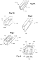
- one of the temples 110 comprises a recess 115 that have a substantially parallelepiped shape.
- the recess 115 is situated at one end of the temple 110 and it outwardly opens at the end of this temple and on a side face of this temple. This end of the temple is situated at the opposite end of the temple end which is fastened to the hinge.
- the temple 110 has a transversal section at the recess 115 which presents a dovetail shape, so that the electronic device 150 can be engaged into this recess 115 by a sliding movement, from the end of the temple toward the hinge.
- one of the faces of the recess 115 comprises a notch 115A for the snap-fastening of the electronic device 150 into the recess 115.
- Each upper corner of the main portion 210 of the frame has a particular shape, enabling the mounting of the ophthalmic lenses in the rims defined by this main portion 210 and the fastening of the hinges.
- each upper corner of the main portion 210 comprises two parts 220, 230 that face each other and that belong to a single piece (these parts are attached together by the rim).
- these two parts 220, 230 are represented at a distance from each other, which enables the mounting of the ophthalmic lens into the rim. But these two parts 220, 230 are designed to mate each other in order to block the ophthalmic lens into the rim.
- each part defines two circular holes 251, 252 that are designed to house two axes of the corresponding hinge.
- One of the two circular holes 252 is provided in a washer that extends at an extremity of the remainder of the corresponding part 220, 230 of the frame main portion.
- the hinge is not shown in the figures because it does not make the focus of the invention. We will only specify that it comprises, in addition to the axes, a main body that is designed to mesh sandwiched between the two parts 220, 230.
- the temples 110 and the main portion 210 of the frame are all manufactured thanks to an additive technology.
- Additive technology is a way to manufacture three-dimensional articles (the other methods consisting in removing material from an initial big block or in molding some material).
- the 3D printer operates thanks to a SLS technology, by laser sintering of polyamide powder PA12, in successive layers of 60 micrometers.
- each printed article 100, 200 is manufactured with two parts and with a temporary connection that links said two parts.
- This step of finishing can consist in polishing the external faces of the printed articles 100, 200.
- This finishing step can be implemented in different ways, automatically or manually, for instance by mechanical polishing, by grinding or by sand blasting.
- step of finishing is implemented by tribofinishing, thanks to a vibratory bowl.
- This well known method consists in putting the printed articles 100, 200 in a vibrator bowl and in mixing them with abrasives (for instance wood pieces).
- This step is followed by a last step of unlinking said temporary connection in order to separate said two parts.
- each article 100, 200 with two parts linked together by a temporary connection is to protect some of the sharp edges of the temples 110 and of the frame main portion 210 during the finishing step.
- the temples 110 and the main portion 210 of the frame need to present sharp edges, in particular for aesthetical and mechanical purposes. Manufacturing the articles in two parts enables one of these parts to protect the sharp edges of the other part. To this end, the first part needs to be situated in front of the sharp edges of the other part to be protected.
- one of the parts is an eyewear piece (here a temple) and the other part is a mask entirely separable from the eyewear piece.
- the said two parts belong to the same portion (here the main portion), each part having a sharp edge protected by the sharp edge of the other part.
- a third part a mask linked to the two first parts by temporary connections.
- the article 100 manufactured by the 3D printer comprises the temple 110 and a mask 160 linked together by a temporary connection 140.
- the mask 160 is situated where sharp edges of the temple 110 need to be protected.
- the need is to keep a nominal clearance between the electronic device 150 and the recess 115 (to ensure a good sliding and a good blocking of these two elements relative to each other).
- the sharp edges 111 that need to be protected are thus the external edges of the recess 115.
- the mask 160 is printed together with the temple 110, during a single operation, so that it presents protection edges 161 that face the sharp edges 111 of the recess 115 to be protected.
- the verb "face” means that the protection edges 161 of the mask 160 are situated along the sharp edges 111 to be protected, at a distance less than 1 millimeter. Moreover, the mask 160 is situated so that its external face (the one defining the protection edges 161) extends in continuation of an external face of the temple 110 (the one defining the sharp edges 111) or projects outward from this external face.
- the mask 160 and the temple 110 are printed in the same material but in a variant, different materials could be employed.
- the mask 160 has a picture-frame shape (with a lateral wall 162 and two ridges 163 that border at the rear the external face of the lateral wall 162 in order to enable the sliding of the mask 160 out of the recess 115).
- the temporary connection 140 between the mask 160 and the temple 110 comprises an inhomogeneity of presence of material.
- the mask 160 and the temple 110 are not linked together by a uniform surface or by a uniform edge. On the contrary, they are linked by a matrix of linking points or pins.
- the temporary connection 140 comprises 4 brittle pins 140A, 140B printed together with the mask 160 and the temple 110.
- Each pin 140A, 140B extends from an internal lateral face of the recess 115 toward the opposite internal lateral face, through an opening 164 provided in the lateral wall 162 of the mask 160. These pins 140A, 140B are manufactured so that they do not touch the edges of these openings 164.
- pins 140A, 140B can be broken by hand or cut with a knife after the finishing step, so that the mask 160 can be extracted from the recess 115, by a sliding movement.
- the pins 140A, 140B are breakable with a force lower than the force required to break any other part of the printed article 100.
- the mask could be attached to the frame thanks to another kind of temporary connection.
- Figure 5 represents a mask 260 that is situated in the housing 213 of the main body of the hinge, in order to protect the sharp edges 211 of this housing 213 and the washers in which the circular holes 252 are provided.
- the mask is not linked to the main portion 210 of the frame by pins.
- breakable points that extend between the mask 260 and each part 220, 230 of the main portion 210.
- These breakable points are manufactured together with the mask 260 and the main portion. They have a diameter lower than 0,5 millimeter in order to be easy to break, and a height lower than 0,1 millimeter.
- breakable points are distributed along the edges of the hinge housing 213, in none-functional and/or invisible areas. For instance, there is no breakable point on the washers to prevent any problem of mounting the axes of the hinge in the circular holes 252 or any aesthetical problem.
- the mask 260 could be linked to each part 220, 230 of the main portion 210 of the frame by a breakable line extending along the edges of the hinge housing 213.
- a breakable line could have a width lower than 0,3 millimeter in order to be easy to break, and a height lower than 0,1 millimeter.
- the mask 260 could be linked to each part 220, 230 of the main portion 210 of the frame by a breakable surface of contact.
- Each of these parts 220, 230 has a half-shell shape, with an end-edge 212 that faces the end-edge 212 of the other part (said end-edge 212 having a ridge that defines the said sharp edge 211 as shown in Figure 6 ).
- each part 220, 230 defines a surface herein called "surface of contact 212" because it is manufactured in contact with a corresponding surface of the mask 260.
- the hinge housing 213 is defined between two opposite surfaces of contact 212, and the mask 260 is manufactured between these two opposite surfaces of contact 121, stick therebetween.
- the idea is to create a weak and pre-cut surface that will be easy to break after the polishing step.
- the additive manufacturing technology comprising a powder fusion operation
- said weak surface of contact is the result of an imperfect fusion of the powder.
- said weak surface of contact would be the result of an imperfect solidification of the fluid.
- the weak surface of contact is obtained by an inhomogeneity in the fusion of powder or in the solidification of fluid.
- a first solution could consist in decreasing the power of the laser when generating these surfaces of contact.
- Another solution could consist in designing the article with the surfaces of contact of the parts 220, 230 very close to the mask 260 (but at a distance from it), in order to profit from the lack of accuracy of the 3D printer.
- the distance (between two layers of material or between two fusion of solidification points) is adjusted in order to create a link solid enough to resist during the finishing step, and weak enough to be manually broken.
- This distance is defined as the threshold of distance to get a fusion or a solidification in the process of additive manufacturing technology.
- these two parts 220, 230 belong to a single piece (the main portion 210) and they are designed to mate each other in order to block an ophthalmic lens in the corresponding rim.
- each of the two parts 220, 230 comprises a main body 225, 235 that has a half-shell shape and that forms a portion of the rim and a portion of the hinge holder.
- the main bodies 225, 235 of these two parts 220, 230 are adjacent to each other in the sense that they have adjacent edges 221, 231 that are designed to come into contact with each other and to interlock.
- these adjacent edges 221, 231 extend from the hinge housing 213 to the opening defined by the corresponding rim.
- a purpose of this matching is to hide at best the line of connection between these two parts 220, 230 on the front face of the main portion of the frame, when the lens is mounted into the rim.
- one of the two parts 220 comprises a rabbet 226 that projects from the main body 225 of this part and that covers a portion of the main body 235 of the other part 230.
- this rabbet 226 is designed to engage into a groove 236 provided in correspondence in the main body 235 of said other part 230.
- One of the adjacent edges 221 lies along the rabbet 226 and the other adjacent edge 231 lies along the groove 236.
- a purpose of the invention is to preserve the adjacent edge 221 of this rabbet 226 and the corresponding adjacent edge 231 of the groove 236 to ensure a perfect junction between these edges after the polishing step.
- the rear face 222 of the rabbet 231 and the front face 232 of the groove 236 are linked to each other by a first temporary connection 242.
- the lateral faces 223, 233 of the main bodies 225, 235 are also linked to each other by a second temporary connection 243.
- the first and second temporary connections 242, 243 form a global temporary connection 240 that links the two parts 220, 230 of the main portion 210 of the frame and that is manually breakable.
- the used temporary connection is of the type "breakable surface" , as described above.
- these two parts 220, 230 are designed to be manufactured so that:
- the global temporary connection 240 resists the efforts exerted by the abrasives. Moreover, once the finishing step has been completed, it is possible to break this global temporary connection 240 manually and easily, with a reduced force, which avoids the breaking of the remainder of the main portion. Indeed, the remainder of the main portion is much more solid that this temporary connection, that is why it can be told that the two parts 220, 230 are linked together by a "definitive connection” around the rim, and by a global “temporary connection” 240 in the corner of the main portion.
- the mask could be printed in a material less rigid that the one of the temple (for instance in an elastomeric material) so that it can be easily removed from the temple, without breaking any pin.
- provision could be made for the mask to not be discarded after the step of breaking the temporary connection.
- the mask could be employed as a cover to close the recess provided in one of the temples of the frame.
Landscapes
- Engineering & Computer Science (AREA)
- Chemical & Material Sciences (AREA)
- Materials Engineering (AREA)
- Physics & Mathematics (AREA)
- Optics & Photonics (AREA)
- Manufacturing & Machinery (AREA)
- Mechanical Engineering (AREA)
- Health & Medical Sciences (AREA)
- General Physics & Mathematics (AREA)
- Ophthalmology & Optometry (AREA)
Claims (10)
- Verfahren zum Fertigen eines dreidimensionalen Erzeugnisses (100; 200), umfassend:- einen Schritt des Herstellens des Erzeugnisses (100; 200) durch eine additive Fertigungstechnologie, wobei das Erzeugnis (100; 200) mindestens zwei Teile (110, 160; 220, 230, 260) umfasst, die Oberflächen aufweisen, die einander zumindest teilweise zugewandt sind oder Kanten (111, 161; 211, 221, 231, 261) aufweisen, die einander zumindest teilweise zugewandt sind, und- einen Schritt der Endbearbeitung des Erzeugnisses (100; 200),wobei die additive Fertigungstechnologie einen Vorgang des Schmelzens von Pulver oder des Erstarrens eines Fluids umfasst,wobei die beiden Teile (110, 160; 220, 230, 260) zusammen mit einer vorübergehenden Verbindung (140; 240) hergestellt werden, wobei die vorübergehende Verbindung (140; 240) die zwei Teile verbindet und wobei die vorübergehende Verbindung (140; 240) eine Inhomogenität entlang der Oberflächen oder der Kanten umfasst,wobei die Inhomogenität eine Inhomogenität des Schmelzens von Pulver oder des Erstarrens von Fluid entlang der Oberflächen oder der Kanten umfasst, undwobei das Verfahren nach dem Schritt der Endbearbeitung einen Schritt des Trennens der vorübergehenden Verbindung (140; 240) umfasst, um die zwei Teile (110, 160; 220, 230, 260) zu trennen.
- Verfahren nach Anspruch 1, wobei die vorübergehende Verbindung (140; 240) mit einer Kraft aufbrechbar ist, die geringer ist als die Kraft, die erforderlich ist, um jeglichen anderen Teil des Erzeugnisses (100; 200) zu zerbrechen.
- Verfahren nach einem der Ansprüche 1 und 2, wobei einer der beiden Teile eine Maske (160) ist, die vollständig von dem anderen Teil (110) trennbar ist, wobei die Maske in einer Nut angeordnet ist, die in einer Außenoberfläche des anderen Teils vertieft ist und wobei die Maske von der Außenoberfläche vorsteht.
- Verfahren nach einem der Ansprüche 1 bis 3, bei dem die beiden Teile (220, 230) auch durch eine endgültige Verbindung miteinander verbunden werden, sodass diese beiden Teile (220, 230) auch dann ein einziges Stück ausbilden, wenn die vorübergehende Verbindung (240) getrennt wird.
- Verfahren nach einem der vorhergehenden Ansprüche, wobei:- jeder Teil (220, 230) einen Hauptkörper (225, 235) umfasst, der an den Hauptkörper des anderen Teils angrenzt,- einer der zwei Teile (220) ferner einen Falz (226) umfasst, der einen Abschnitt des Hauptkörpers (235) des anderen Teils (230) bedeckt, und- die vorübergehende Verbindung (240) zwischen dem Falz (226) und dem Hauptkörper (235) des anderen Teils (230) angeordnet ist.
- Verfahren nach einem der vorhergehenden Ansprüche, wobei mindestens einer der zwei Teile (110) ein Gehäuse (115) für eine elektronische Vorrichtung (150) definiert.
- Verfahren nach einem der vorhergehenden Ansprüche, wobei mindestens einer der zwei Teile (110; 220, 230) einen Teil eines Brillengestells ausbildet.
- Verfahren nach einem der vorhergehenden Ansprüche, wobei der Schritt der Endbearbeitung ein mechanisches Polieren des Erzeugnisses (100; 200) umfasst, beispielsweise eine Tribo-Endbearbeitung des Erzeugnisses (100; 200).
- Dreidimensionales Erzeugnis (100; 200), hergestellt durch eine additive Fertigungstechnologie, die einen Vorgang des Schmelzens von Pulver oder des Erstarrens eines Fluids umfasst, umfassend:- mindestens zwei Teile (110, 160; 220, 230, 260), die Oberflächen aufweisen, die einander zumindest teilweise zugewandt sind, oder Kanten (111, 161; 221, 231, 261) aufweisen, die einander zumindest teilweise zugewandt sind, und- eine vorübergehende Verbindung (140; 240), die die zwei Teile (110, 160; 220, 230, 260) verbindet und die eine Inhomogenität entlang der Oberflächen oder der Kanten aufweist,wobei die beiden Teile (110, 160; 220, 230, 260) und die vorübergehende Verbindung (140; 240) derart gestaltet sind, dass die vorübergehende Verbindung (140; 240) während eines Schritts der Endbearbeitung des Erzeugnisses (100; 200) mindestens einen der beiden Teile oder eine der Kanten bewahrt undwobei die Inhomogenität eine Inhomogenität des Schmelzens von Pulver oder des Erstarrens von Fluid entlang der Oberflächen oder der Kanten umfasst.
- Dreidimensionales Erzeugnis (100; 200) nach Anspruch 9, wobei einer der mindestens zwei Teile (110) einen Abschnitt eines Brillenbügels mit einer Aussparung (115) ausbildet, wobei der andere der mindestens zwei Teile (160) vorübergehend in der Aussparung (115) befestigt wird.
Applications Claiming Priority (2)
| Application Number | Priority Date | Filing Date | Title |
|---|---|---|---|
| EP17170718.5A EP3401079A1 (de) | 2017-05-11 | 2017-05-11 | Verfahren zur herstellung eines dreidimensionalen objektes mittels einer generativen fertigungstechnologie |
| PCT/EP2018/062142 WO2018206724A1 (en) | 2017-05-11 | 2018-05-09 | Method for manufacturing a three-dimensional article by an additive manufacturing technology |
Publications (2)
| Publication Number | Publication Date |
|---|---|
| EP3621783A1 EP3621783A1 (de) | 2020-03-18 |
| EP3621783B1 true EP3621783B1 (de) | 2023-04-19 |
Family
ID=58709279
Family Applications (2)
| Application Number | Title | Priority Date | Filing Date |
|---|---|---|---|
| EP17170718.5A Withdrawn EP3401079A1 (de) | 2017-05-11 | 2017-05-11 | Verfahren zur herstellung eines dreidimensionalen objektes mittels einer generativen fertigungstechnologie |
| EP18721424.2A Active EP3621783B1 (de) | 2017-05-11 | 2018-05-09 | Verfahren zur herstellung eines dreidimensionalen objektes mittels einer generativen fertigungstechnologie |
Family Applications Before (1)
| Application Number | Title | Priority Date | Filing Date |
|---|---|---|---|
| EP17170718.5A Withdrawn EP3401079A1 (de) | 2017-05-11 | 2017-05-11 | Verfahren zur herstellung eines dreidimensionalen objektes mittels einer generativen fertigungstechnologie |
Country Status (4)
| Country | Link |
|---|---|
| US (1) | US11639033B2 (de) |
| EP (2) | EP3401079A1 (de) |
| CN (1) | CN110545985B (de) |
| WO (1) | WO2018206724A1 (de) |
Families Citing this family (3)
| Publication number | Priority date | Publication date | Assignee | Title |
|---|---|---|---|---|
| USD898813S1 (en) * | 2017-09-29 | 2020-10-13 | Mitsui Chemicals, Inc. | Battery for electronic eyeglasses |
| EP3797905A1 (de) | 2019-09-30 | 2021-03-31 | Siemens Aktiengesellschaft | Verfahren zur modularen generativen fertigung |
| AT525346B1 (de) * | 2022-07-07 | 2023-03-15 | Genera Printer Gmbh | Verfahren zur additiven Fertigung |
Citations (1)
| Publication number | Priority date | Publication date | Assignee | Title |
|---|---|---|---|---|
| EP2526141B1 (de) * | 2010-01-21 | 2017-07-05 | Mykita Studio GmbH | Verfahren zur oberflächenbehandlung |
Family Cites Families (5)
| Publication number | Priority date | Publication date | Assignee | Title |
|---|---|---|---|---|
| KR20170014619A (ko) * | 2015-07-30 | 2017-02-08 | 주식회사 대건테크 | 레이저 소결식 3차원 프린팅 조형물의 서포트 구조체 |
| WO2017071762A1 (en) * | 2015-10-29 | 2017-05-04 | Hewlett-Packard Development Company, L.P. | Three-dimensional part production |
| US10488676B2 (en) * | 2016-10-28 | 2019-11-26 | Chemistrie Properties, Inc. | Universal method of manufacturing magnetically attachable supplemental eyeglasses utilizing magnets embedded in an on-demand formed frame front and eyeglasses formed thereby |
| EP3551365B1 (de) * | 2016-12-06 | 2022-03-16 | Markforged, Inc. | Verfahren zur generativen fertigung mit zuführung von wärmegebogenem material |
| FR3065178B1 (fr) * | 2017-04-14 | 2022-04-29 | C Tec Constellium Tech Center | Procede de fabrication d'une piece en alliage d'aluminium |
-
2017
- 2017-05-11 EP EP17170718.5A patent/EP3401079A1/de not_active Withdrawn
-
2018
- 2018-05-09 EP EP18721424.2A patent/EP3621783B1/de active Active
- 2018-05-09 CN CN201880027355.6A patent/CN110545985B/zh active Active
- 2018-05-09 WO PCT/EP2018/062142 patent/WO2018206724A1/en not_active Ceased
- 2018-05-09 US US16/612,312 patent/US11639033B2/en active Active
Patent Citations (1)
| Publication number | Priority date | Publication date | Assignee | Title |
|---|---|---|---|---|
| EP2526141B1 (de) * | 2010-01-21 | 2017-07-05 | Mykita Studio GmbH | Verfahren zur oberflächenbehandlung |
Also Published As
| Publication number | Publication date |
|---|---|
| US20200164591A1 (en) | 2020-05-28 |
| US11639033B2 (en) | 2023-05-02 |
| EP3621783A1 (de) | 2020-03-18 |
| EP3401079A1 (de) | 2018-11-14 |
| CN110545985B (zh) | 2022-07-15 |
| CN110545985A (zh) | 2019-12-06 |
| WO2018206724A1 (en) | 2018-11-15 |
Similar Documents
| Publication | Publication Date | Title |
|---|---|---|
| US12271058B2 (en) | Method for manufacturing at least one ophthalmic lens | |
| US11639033B2 (en) | Method for manufacturing a three-dimensional article by an additive manufacturing technology | |
| US10459247B2 (en) | Method for manufacturing an ophthalmic lens comprising a marking step for producing permanent technical marks on said ophthalmic lens | |
| JP5052442B2 (ja) | リムレス眼鏡の製造方法及び該方法で使用するために適したマスク | |
| JP2017522617A (ja) | ノーズブリッジと接合された部分を有するアイウェアフレームを製造する方法 | |
| BR112015030139B1 (pt) | Processo e sistema de fabricação de uma lente oftálmica | |
| AU2016369930B2 (en) | Eyeglass temple | |
| US20170182681A1 (en) | Additive manufacturing of molds and methods of making molds and devices therefrom | |
| JP2019507901A (ja) | 剛性金属コア及びポリマー材料外部被膜を備える物体の製造方法及び得られる物体 | |
| US11370175B2 (en) | Optical element, assembly comprising such an optical element and method of manufacturing an optical element | |
| CN107962348A (zh) | 壳体加工方法、壳体和终端设备 | |
| EP3224032B1 (de) | Verfahren zur herstellung einer linse für brillen | |
| KR101284123B1 (ko) | 안경테의 외측으로 사출성형이 가능한 안경테 제조용 금형 및 그 금형방법 | |
| US20150293375A1 (en) | Method Of Producing A Spectacle Lens Having A Decorative Element | |
| US7172279B1 (en) | Safety eyeglasses with integral side shield and temple | |
| CN106030378A (zh) | 用于制造配备有插入件的眼科镜片的模具和方法 | |
| JP6856841B2 (ja) | 眼鏡レンズ | |
| EP4357115A1 (de) | Verfahren zur herstellung einer transparenten kunststofflinse mit eingebetteten dekorativen elementen | |
| US11787136B2 (en) | Method for manufacturing an ophthalmic lens to be mounted in a frame, ophthalmic lens, frame and eyeglasses equipment | |
| CN122003323A (zh) | 用于制造光学制品的方法 | |
| HK40003537A (en) | Corrective lens and shield in unitary structure and method | |
| FR2835931A1 (fr) | Procede pour fabriquer un verre de lunettes correcteur et palet correspondant | |
| HK1262727A1 (en) | Method for producing an object comprising a rigid metal core and a polymer-material external coating, and object obtained therewith |
Legal Events
| Date | Code | Title | Description |
|---|---|---|---|
| STAA | Information on the status of an ep patent application or granted ep patent |
Free format text: STATUS: UNKNOWN |
|
| STAA | Information on the status of an ep patent application or granted ep patent |
Free format text: STATUS: THE INTERNATIONAL PUBLICATION HAS BEEN MADE |
|
| PUAI | Public reference made under article 153(3) epc to a published international application that has entered the european phase |
Free format text: ORIGINAL CODE: 0009012 |
|
| STAA | Information on the status of an ep patent application or granted ep patent |
Free format text: STATUS: REQUEST FOR EXAMINATION WAS MADE |
|
| 17P | Request for examination filed |
Effective date: 20191120 |
|
| AK | Designated contracting states |
Kind code of ref document: A1 Designated state(s): AL AT BE BG CH CY CZ DE DK EE ES FI FR GB GR HR HU IE IS IT LI LT LU LV MC MK MT NL NO PL PT RO RS SE SI SK SM TR |
|
| AX | Request for extension of the european patent |
Extension state: BA ME |
|
| DAV | Request for validation of the european patent (deleted) | ||
| DAX | Request for extension of the european patent (deleted) | ||
| STAA | Information on the status of an ep patent application or granted ep patent |
Free format text: STATUS: EXAMINATION IS IN PROGRESS |
|
| 17Q | First examination report despatched |
Effective date: 20211222 |
|
| RIC1 | Information provided on ipc code assigned before grant |
Ipc: G02C 11/00 20060101ALN20221017BHEP Ipc: G02C 1/08 20060101ALN20221017BHEP Ipc: B29D 12/02 20060101ALI20221017BHEP Ipc: B33Y 80/00 20150101ALI20221017BHEP Ipc: B33Y 10/00 20150101ALI20221017BHEP Ipc: B29C 64/40 20170101ALI20221017BHEP Ipc: B29C 64/188 20170101ALI20221017BHEP Ipc: B29C 64/10 20170101AFI20221017BHEP |
|
| RIC1 | Information provided on ipc code assigned before grant |
Ipc: G02C 11/00 20060101ALN20221122BHEP Ipc: G02C 1/08 20060101ALN20221122BHEP Ipc: B29D 12/02 20060101ALI20221122BHEP Ipc: B33Y 80/00 20150101ALI20221122BHEP Ipc: B33Y 10/00 20150101ALI20221122BHEP Ipc: B29C 64/40 20170101ALI20221122BHEP Ipc: B29C 64/188 20170101ALI20221122BHEP Ipc: B29C 64/10 20170101AFI20221122BHEP |
|
| GRAP | Despatch of communication of intention to grant a patent |
Free format text: ORIGINAL CODE: EPIDOSNIGR1 |
|
| STAA | Information on the status of an ep patent application or granted ep patent |
Free format text: STATUS: GRANT OF PATENT IS INTENDED |
|
| INTG | Intention to grant announced |
Effective date: 20230102 |
|
| GRAS | Grant fee paid |
Free format text: ORIGINAL CODE: EPIDOSNIGR3 |
|
| GRAA | (expected) grant |
Free format text: ORIGINAL CODE: 0009210 |
|
| STAA | Information on the status of an ep patent application or granted ep patent |
Free format text: STATUS: THE PATENT HAS BEEN GRANTED |
|
| AK | Designated contracting states |
Kind code of ref document: B1 Designated state(s): AL AT BE BG CH CY CZ DE DK EE ES FI FR GB GR HR HU IE IS IT LI LT LU LV MC MK MT NL NO PL PT RO RS SE SI SK SM TR |
|
| REG | Reference to a national code |
Ref country code: GB Ref legal event code: FG4D |
|
| REG | Reference to a national code |
Ref country code: DE Ref legal event code: R096 Ref document number: 602018048565 Country of ref document: DE |
|
| REG | Reference to a national code |
Ref country code: CH Ref legal event code: EP |
|
| REG | Reference to a national code |
Ref country code: IE Ref legal event code: FG4D |
|
| REG | Reference to a national code |
Ref country code: AT Ref legal event code: REF Ref document number: 1560870 Country of ref document: AT Kind code of ref document: T Effective date: 20230515 |
|
| P01 | Opt-out of the competence of the unified patent court (upc) registered |
Effective date: 20230525 |
|
| REG | Reference to a national code |
Ref country code: LT Ref legal event code: MG9D |
|
| REG | Reference to a national code |
Ref country code: NL Ref legal event code: MP Effective date: 20230419 |
|
| REG | Reference to a national code |
Ref country code: AT Ref legal event code: MK05 Ref document number: 1560870 Country of ref document: AT Kind code of ref document: T Effective date: 20230419 |
|
| PG25 | Lapsed in a contracting state [announced via postgrant information from national office to epo] |
Ref country code: NL Free format text: LAPSE BECAUSE OF FAILURE TO SUBMIT A TRANSLATION OF THE DESCRIPTION OR TO PAY THE FEE WITHIN THE PRESCRIBED TIME-LIMIT Effective date: 20230419 |
|
| PG25 | Lapsed in a contracting state [announced via postgrant information from national office to epo] |
Ref country code: SE Free format text: LAPSE BECAUSE OF FAILURE TO SUBMIT A TRANSLATION OF THE DESCRIPTION OR TO PAY THE FEE WITHIN THE PRESCRIBED TIME-LIMIT Effective date: 20230419 Ref country code: PT Free format text: LAPSE BECAUSE OF FAILURE TO SUBMIT A TRANSLATION OF THE DESCRIPTION OR TO PAY THE FEE WITHIN THE PRESCRIBED TIME-LIMIT Effective date: 20230821 Ref country code: NO Free format text: LAPSE BECAUSE OF FAILURE TO SUBMIT A TRANSLATION OF THE DESCRIPTION OR TO PAY THE FEE WITHIN THE PRESCRIBED TIME-LIMIT Effective date: 20230719 Ref country code: ES Free format text: LAPSE BECAUSE OF FAILURE TO SUBMIT A TRANSLATION OF THE DESCRIPTION OR TO PAY THE FEE WITHIN THE PRESCRIBED TIME-LIMIT Effective date: 20230419 Ref country code: AT Free format text: LAPSE BECAUSE OF FAILURE TO SUBMIT A TRANSLATION OF THE DESCRIPTION OR TO PAY THE FEE WITHIN THE PRESCRIBED TIME-LIMIT Effective date: 20230419 |
|
| PG25 | Lapsed in a contracting state [announced via postgrant information from national office to epo] |
Ref country code: RS Free format text: LAPSE BECAUSE OF FAILURE TO SUBMIT A TRANSLATION OF THE DESCRIPTION OR TO PAY THE FEE WITHIN THE PRESCRIBED TIME-LIMIT Effective date: 20230419 Ref country code: PL Free format text: LAPSE BECAUSE OF FAILURE TO SUBMIT A TRANSLATION OF THE DESCRIPTION OR TO PAY THE FEE WITHIN THE PRESCRIBED TIME-LIMIT Effective date: 20230419 Ref country code: LV Free format text: LAPSE BECAUSE OF FAILURE TO SUBMIT A TRANSLATION OF THE DESCRIPTION OR TO PAY THE FEE WITHIN THE PRESCRIBED TIME-LIMIT Effective date: 20230419 Ref country code: LT Free format text: LAPSE BECAUSE OF FAILURE TO SUBMIT A TRANSLATION OF THE DESCRIPTION OR TO PAY THE FEE WITHIN THE PRESCRIBED TIME-LIMIT Effective date: 20230419 Ref country code: IS Free format text: LAPSE BECAUSE OF FAILURE TO SUBMIT A TRANSLATION OF THE DESCRIPTION OR TO PAY THE FEE WITHIN THE PRESCRIBED TIME-LIMIT Effective date: 20230819 Ref country code: HR Free format text: LAPSE BECAUSE OF FAILURE TO SUBMIT A TRANSLATION OF THE DESCRIPTION OR TO PAY THE FEE WITHIN THE PRESCRIBED TIME-LIMIT Effective date: 20230419 Ref country code: GR Free format text: LAPSE BECAUSE OF FAILURE TO SUBMIT A TRANSLATION OF THE DESCRIPTION OR TO PAY THE FEE WITHIN THE PRESCRIBED TIME-LIMIT Effective date: 20230720 Ref country code: AL Free format text: LAPSE BECAUSE OF FAILURE TO SUBMIT A TRANSLATION OF THE DESCRIPTION OR TO PAY THE FEE WITHIN THE PRESCRIBED TIME-LIMIT Effective date: 20230419 |
|
| PG25 | Lapsed in a contracting state [announced via postgrant information from national office to epo] |
Ref country code: FI Free format text: LAPSE BECAUSE OF FAILURE TO SUBMIT A TRANSLATION OF THE DESCRIPTION OR TO PAY THE FEE WITHIN THE PRESCRIBED TIME-LIMIT Effective date: 20230419 |
|
| REG | Reference to a national code |
Ref country code: CH Ref legal event code: PL |
|
| PG25 | Lapsed in a contracting state [announced via postgrant information from national office to epo] |
Ref country code: SK Free format text: LAPSE BECAUSE OF FAILURE TO SUBMIT A TRANSLATION OF THE DESCRIPTION OR TO PAY THE FEE WITHIN THE PRESCRIBED TIME-LIMIT Effective date: 20230419 |
|
| PG25 | Lapsed in a contracting state [announced via postgrant information from national office to epo] |
Ref country code: MC Free format text: LAPSE BECAUSE OF FAILURE TO SUBMIT A TRANSLATION OF THE DESCRIPTION OR TO PAY THE FEE WITHIN THE PRESCRIBED TIME-LIMIT Effective date: 20230419 |
|
| REG | Reference to a national code |
Ref country code: DE Ref legal event code: R097 Ref document number: 602018048565 Country of ref document: DE |
|
| REG | Reference to a national code |
Ref country code: BE Ref legal event code: MM Effective date: 20230531 |
|
| PG25 | Lapsed in a contracting state [announced via postgrant information from national office to epo] |
Ref country code: SM Free format text: LAPSE BECAUSE OF FAILURE TO SUBMIT A TRANSLATION OF THE DESCRIPTION OR TO PAY THE FEE WITHIN THE PRESCRIBED TIME-LIMIT Effective date: 20230419 Ref country code: SK Free format text: LAPSE BECAUSE OF FAILURE TO SUBMIT A TRANSLATION OF THE DESCRIPTION OR TO PAY THE FEE WITHIN THE PRESCRIBED TIME-LIMIT Effective date: 20230419 Ref country code: RO Free format text: LAPSE BECAUSE OF FAILURE TO SUBMIT A TRANSLATION OF THE DESCRIPTION OR TO PAY THE FEE WITHIN THE PRESCRIBED TIME-LIMIT Effective date: 20230419 Ref country code: MC Free format text: LAPSE BECAUSE OF FAILURE TO SUBMIT A TRANSLATION OF THE DESCRIPTION OR TO PAY THE FEE WITHIN THE PRESCRIBED TIME-LIMIT Effective date: 20230419 Ref country code: LU Free format text: LAPSE BECAUSE OF NON-PAYMENT OF DUE FEES Effective date: 20230509 Ref country code: LI Free format text: LAPSE BECAUSE OF NON-PAYMENT OF DUE FEES Effective date: 20230531 Ref country code: EE Free format text: LAPSE BECAUSE OF FAILURE TO SUBMIT A TRANSLATION OF THE DESCRIPTION OR TO PAY THE FEE WITHIN THE PRESCRIBED TIME-LIMIT Effective date: 20230419 Ref country code: DK Free format text: LAPSE BECAUSE OF FAILURE TO SUBMIT A TRANSLATION OF THE DESCRIPTION OR TO PAY THE FEE WITHIN THE PRESCRIBED TIME-LIMIT Effective date: 20230419 Ref country code: CZ Free format text: LAPSE BECAUSE OF FAILURE TO SUBMIT A TRANSLATION OF THE DESCRIPTION OR TO PAY THE FEE WITHIN THE PRESCRIBED TIME-LIMIT Effective date: 20230419 Ref country code: CH Free format text: LAPSE BECAUSE OF NON-PAYMENT OF DUE FEES Effective date: 20230531 |
|
| PLBE | No opposition filed within time limit |
Free format text: ORIGINAL CODE: 0009261 |
|
| STAA | Information on the status of an ep patent application or granted ep patent |
Free format text: STATUS: NO OPPOSITION FILED WITHIN TIME LIMIT |
|
| REG | Reference to a national code |
Ref country code: IE Ref legal event code: MM4A |
|
| 26N | No opposition filed |
Effective date: 20240122 |
|
| PG25 | Lapsed in a contracting state [announced via postgrant information from national office to epo] |
Ref country code: IE Free format text: LAPSE BECAUSE OF NON-PAYMENT OF DUE FEES Effective date: 20230509 |
|
| PG25 | Lapsed in a contracting state [announced via postgrant information from national office to epo] |
Ref country code: IE Free format text: LAPSE BECAUSE OF NON-PAYMENT OF DUE FEES Effective date: 20230509 |
|
| PG25 | Lapsed in a contracting state [announced via postgrant information from national office to epo] |
Ref country code: SI Free format text: LAPSE BECAUSE OF FAILURE TO SUBMIT A TRANSLATION OF THE DESCRIPTION OR TO PAY THE FEE WITHIN THE PRESCRIBED TIME-LIMIT Effective date: 20230419 |
|
| PG25 | Lapsed in a contracting state [announced via postgrant information from national office to epo] |
Ref country code: SI Free format text: LAPSE BECAUSE OF FAILURE TO SUBMIT A TRANSLATION OF THE DESCRIPTION OR TO PAY THE FEE WITHIN THE PRESCRIBED TIME-LIMIT Effective date: 20230419 Ref country code: BE Free format text: LAPSE BECAUSE OF NON-PAYMENT OF DUE FEES Effective date: 20230531 |
|
| PG25 | Lapsed in a contracting state [announced via postgrant information from national office to epo] |
Ref country code: BG Free format text: LAPSE BECAUSE OF FAILURE TO SUBMIT A TRANSLATION OF THE DESCRIPTION OR TO PAY THE FEE WITHIN THE PRESCRIBED TIME-LIMIT Effective date: 20230419 |
|
| PG25 | Lapsed in a contracting state [announced via postgrant information from national office to epo] |
Ref country code: BG Free format text: LAPSE BECAUSE OF FAILURE TO SUBMIT A TRANSLATION OF THE DESCRIPTION OR TO PAY THE FEE WITHIN THE PRESCRIBED TIME-LIMIT Effective date: 20230419 |
|
| PGFP | Annual fee paid to national office [announced via postgrant information from national office to epo] |
Ref country code: DE Payment date: 20250529 Year of fee payment: 8 |
|
| PGFP | Annual fee paid to national office [announced via postgrant information from national office to epo] |
Ref country code: GB Payment date: 20250527 Year of fee payment: 8 |
|
| PGFP | Annual fee paid to national office [announced via postgrant information from national office to epo] |
Ref country code: IT Payment date: 20250521 Year of fee payment: 8 |
|
| PGFP | Annual fee paid to national office [announced via postgrant information from national office to epo] |
Ref country code: FR Payment date: 20250526 Year of fee payment: 8 |
|
| PG25 | Lapsed in a contracting state [announced via postgrant information from national office to epo] |
Ref country code: CY Free format text: LAPSE BECAUSE OF FAILURE TO SUBMIT A TRANSLATION OF THE DESCRIPTION OR TO PAY THE FEE WITHIN THE PRESCRIBED TIME-LIMIT; INVALID AB INITIO Effective date: 20180509 |
|
| PG25 | Lapsed in a contracting state [announced via postgrant information from national office to epo] |
Ref country code: HU Free format text: LAPSE BECAUSE OF FAILURE TO SUBMIT A TRANSLATION OF THE DESCRIPTION OR TO PAY THE FEE WITHIN THE PRESCRIBED TIME-LIMIT; INVALID AB INITIO Effective date: 20180509 |
|
| PG25 | Lapsed in a contracting state [announced via postgrant information from national office to epo] |
Ref country code: TR Free format text: LAPSE BECAUSE OF FAILURE TO SUBMIT A TRANSLATION OF THE DESCRIPTION OR TO PAY THE FEE WITHIN THE PRESCRIBED TIME-LIMIT Effective date: 20230419 |