EP3621753B1 - A method for forming curved lengths of extruded profiles/sections in metal alloys - Google Patents
A method for forming curved lengths of extruded profiles/sections in metal alloys Download PDFInfo
- Publication number
- EP3621753B1 EP3621753B1 EP18725607.8A EP18725607A EP3621753B1 EP 3621753 B1 EP3621753 B1 EP 3621753B1 EP 18725607 A EP18725607 A EP 18725607A EP 3621753 B1 EP3621753 B1 EP 3621753B1
- Authority
- EP
- European Patent Office
- Prior art keywords
- extrusion
- compression element
- orifice
- bore
- extrusion chamber
- Prior art date
- Legal status (The legal status is an assumption and is not a legal conclusion. Google has not performed a legal analysis and makes no representation as to the accuracy of the status listed.)
- Active
Links
Images



Classifications
-
- B—PERFORMING OPERATIONS; TRANSPORTING
- B21—MECHANICAL METAL-WORKING WITHOUT ESSENTIALLY REMOVING MATERIAL; PUNCHING METAL
- B21C—MANUFACTURE OF METAL SHEETS, WIRE, RODS, TUBES, PROFILES OR LIKE SEMI-MANUFACTURED PRODUCTS OTHERWISE THAN BY ROLLING; AUXILIARY OPERATIONS USED IN CONNECTION WITH METAL-WORKING WITHOUT ESSENTIALLY REMOVING MATERIAL
- B21C23/00—Extruding metal; Impact extrusion
-
- B—PERFORMING OPERATIONS; TRANSPORTING
- B21—MECHANICAL METAL-WORKING WITHOUT ESSENTIALLY REMOVING MATERIAL; PUNCHING METAL
- B21C—MANUFACTURE OF METAL SHEETS, WIRE, RODS, TUBES, PROFILES OR LIKE SEMI-MANUFACTURED PRODUCTS OTHERWISE THAN BY ROLLING; AUXILIARY OPERATIONS USED IN CONNECTION WITH METAL-WORKING WITHOUT ESSENTIALLY REMOVING MATERIAL
- B21C23/00—Extruding metal; Impact extrusion
- B21C23/002—Extruding materials of special alloys so far as the composition of the alloy requires or permits special extruding methods of sequences
-
- B—PERFORMING OPERATIONS; TRANSPORTING
- B21—MECHANICAL METAL-WORKING WITHOUT ESSENTIALLY REMOVING MATERIAL; PUNCHING METAL
- B21C—MANUFACTURE OF METAL SHEETS, WIRE, RODS, TUBES, PROFILES OR LIKE SEMI-MANUFACTURED PRODUCTS OTHERWISE THAN BY ROLLING; AUXILIARY OPERATIONS USED IN CONNECTION WITH METAL-WORKING WITHOUT ESSENTIALLY REMOVING MATERIAL
- B21C23/00—Extruding metal; Impact extrusion
- B21C23/02—Making uncoated products
- B21C23/04—Making uncoated products by direct extrusion
- B21C23/08—Making wire, rods or tubes
- B21C23/12—Extruding bent tubes or rods
-
- B—PERFORMING OPERATIONS; TRANSPORTING
- B29—WORKING OF PLASTICS; WORKING OF SUBSTANCES IN A PLASTIC STATE IN GENERAL
- B29C—SHAPING OR JOINING OF PLASTICS; SHAPING OF MATERIAL IN A PLASTIC STATE, NOT OTHERWISE PROVIDED FOR; AFTER-TREATMENT OF THE SHAPED PRODUCTS, e.g. REPAIRING
- B29C48/00—Extrusion moulding, i.e. expressing the moulding material through a die or nozzle which imparts the desired form; Apparatus therefor
- B29C48/03—Extrusion moulding, i.e. expressing the moulding material through a die or nozzle which imparts the desired form; Apparatus therefor characterised by the shape of the extruded material at extrusion
- B29C48/12—Articles with an irregular circumference when viewed in cross-section, e.g. window profiles
-
- B—PERFORMING OPERATIONS; TRANSPORTING
- B29—WORKING OF PLASTICS; WORKING OF SUBSTANCES IN A PLASTIC STATE IN GENERAL
- B29C—SHAPING OR JOINING OF PLASTICS; SHAPING OF MATERIAL IN A PLASTIC STATE, NOT OTHERWISE PROVIDED FOR; AFTER-TREATMENT OF THE SHAPED PRODUCTS, e.g. REPAIRING
- B29C48/00—Extrusion moulding, i.e. expressing the moulding material through a die or nozzle which imparts the desired form; Apparatus therefor
- B29C48/03—Extrusion moulding, i.e. expressing the moulding material through a die or nozzle which imparts the desired form; Apparatus therefor characterised by the shape of the extruded material at extrusion
- B29C48/131—Curved articles
-
- B—PERFORMING OPERATIONS; TRANSPORTING
- B29—WORKING OF PLASTICS; WORKING OF SUBSTANCES IN A PLASTIC STATE IN GENERAL
- B29C—SHAPING OR JOINING OF PLASTICS; SHAPING OF MATERIAL IN A PLASTIC STATE, NOT OTHERWISE PROVIDED FOR; AFTER-TREATMENT OF THE SHAPED PRODUCTS, e.g. REPAIRING
- B29C48/00—Extrusion moulding, i.e. expressing the moulding material through a die or nozzle which imparts the desired form; Apparatus therefor
- B29C48/25—Component parts, details or accessories; Auxiliary operations
- B29C48/36—Means for plasticising or homogenising the moulding material or forcing it through the nozzle or die
- B29C48/475—Means for plasticising or homogenising the moulding material or forcing it through the nozzle or die using pistons, accumulators or press rams
- B29C48/48—Two or more rams or pistons
Definitions
- This disclosure relates to a method and equipment for forming curved metal alloy profiles and more particularly aluminium alloy profiles with predesigned curvature in one extrusion-bending process.
- Aluminium alloy profiles are extensively used as construction elements in industrial manufacturing for the production of ultra-light component structures with a high contour complexity, including seat rails, stringers, and frames in the aircraft industry as well as window frames and roof rails in the automotive industry. This is mainly because they facilitate construction of lightweight, strong, and stiff structures. Taking into account the demand for reduced aerodynamic resistance as well as improved aesthetics, the manufacture and application of highly precise curved aluminium alloy profiles with well adapted properties are quite necessary.
- the challenge to improved production is to manufacture curved profiles with precise curvature, non-distorted cross-sections and well-defined properties at increased productivity.
- US 2004/074275 describes an extru-bending machine that can bend a product by extruding two or more hot metal billets with the machine which consists of an extrusion die holder equipped with conical dies, a container holder heating a two or more-holed container with a conical plug, two or more extrusion stems, a hydraulic power system unit, a relative velocity control unit, and a support frame structure.
- the machine is characterized that, when two or more hot metal billets are welded together inside a conical die cavity and extruded to one product at the die exit, the extru-bending machine can bend the extruded part simultaneously during extruding with a gradient of extrusion velocity on the die's exit owing to the relative moving velocity of two or more extrusion stems.
- SU 837435 which forms the basis for the preamble of claims 1 and 11, describes carrying out extrusion with the simultaneous application of two forces with different speeds to a workpiece, that are directed perpendicular to a side surface of the workpiece on both sides of an extruded profile.
- US 368,314 describes a machine for making curved tubes and pipes.
- the machine comprises a combination of two parallel or substantially parallel pistons, with a receiver for holding the plastic metal or material, a die secured to the receiver, and means for simultaneously and independently actuating the parallel pistons with reference to the die.
- US 2016/114367 describes a container for use in a metal extrusion press.
- the container comprises a mantle having an elongate axial bore therein, the bore having a first transverse axis orthogonal to a second transverse axis, and a plurality of longitudinally extending heating elements accommodated by the mantle adjacent the bore.
- the heating elements are individually controllable for controlling a thermal profile within the container.
- the container also comprises a plurality of temperature sensors configured to measure the thermal profile within the container.
- the temperature sensors comprise a first temperature sensor and a second temperature sensor positioned on opposite sides of the first transverse axis, and a third temperature sensor and a fourth temperature sensor positioned on opposite sides of the second transverse axis.
- GB 1442786 describes a method for making pipe bends or generally curved pipes of thermoplastic material, including the steps of extruding from a pipe extruder head having a mandrel and a die which are arranged eccentrically in relation to each other to define a tubular orifice, a pipe having a wall thickness which varies continuously around its periphery between a maximum and a minimum at opposite locations, passing the pipe directly from the extruder head into a cooling die having the desired constant curvature of the bend, the largest radius of curvature in the cooling die being imparted to the portion of the pipe having the largest wall thickness at the die orifice, and pulling off the curved pipe emerging from the cooling die by haul-off means with hauling wheels having peripheral speeds which are proportional to the radii of curvature of the longitudinal lines on the surface of the pipe bend which the wheels engage, the eccentricity between the mandrel and the die being so adjusted that during the bending process in the curved cooling die, a cross-section having a substantially uniform wall
- a method of extruding a material comprising: providing the material into an extrusion chamber of an extrusion apparatus, wherein the extrusion chamber comprises an extrusion orifice and the extrusion apparatus comprises a first compression element and a second compression element in communication with the interior of the extrusion chamber, the first and second compression elements being independently movable relative to the extrusion chamber; moving the first and second compression elements to compress the material within the extrusion chamber and cause a velocity gradient in the extrusion material across the extrusion orifice; and extruding the material through the extrusion orifice such that the velocity gradient forms an extrudate with a curved profile; wherein moving the first compression element and the second compression element comprises moving the first compression element and the second compression element at different speeds along a common axis, wherein moving the first compression element and the second compression element at different speeds along the common axis comprises moving the first compression element and the second compression element towards each other in opposite directions along the common
- the plane of the cross-section of the extrusion orifice may be parallel to the common axis such that extruding the material through the extrusion orifice comprises extruding the material through the extrusion orifice substantially perpendicular to the common axis.
- a method of extruding a material comprising: providing the material into an extrusion chamber of an extrusion apparatus, wherein the extrusion chamber is a Y-shaped extrusion chamber comprising a first bore, a second bore and a central container, wherein the first bore and the second bore are positioned at an angle to each other and converge to meet the central container, and wherein each of the first bore, the second bore and the central container has an open end opposite to the point of convergence; wherein providing the material into the extrusion chamber comprises placing a first hot or cold billet into the open end of the first bore and placing a second hot or cold billet into the open end of the second bore; wherein the extrusion apparatus further comprises an extrusion die installed at the open end of the central container, the extrusion die comprising an extrusion orifice; and wherein the extrusion apparatus comprises a first compression element and a second compression element, wherein the first and second compression elements are in communication with the
- moving the first and second compression elements may comprise moving the first compression element along a first axis and moving the second compression element along a second axis different to the first axis.
- the first axis and the second axis may be at an angle to one another.
- the plane of the cross-section of the extrusion orifice may be perpendicular to a line that bisects the first and second axes such that extruding the material through the extrusion orifice comprises extruding the material through the extrusion orifice substantially parallel to the line.
- the method of the second aspect may comprise moving the first compression element and second compression element at different speeds.
- the first compression element and second compression element may have different cross-sectional areas perpendicular to their direction of movement.
- the material may be a metal alloy.
- the metal alloy may be aluminium alloy or magnesium alloy.
- the method may further comprise providing a guide means adjacent to the extrusion orifice to control curvature of the extruded material.
- the method may further comprise providing a mandrel in the extrusion chamber opposite to the extrusion orifice. Extruding the material through the extrusion orifice may comprise extruding the material with a hollow cross-section defined by the mandrel and orifice. The plane of the cross-section of the mandrel that defines the hollow cross-section of the extruded material may be parallel to the plane of the cross-section of the extrusion orifice.
- the method may further comprise preheating the material before providing it into the extrusion chamber.
- the method may comprise adjusting the speed of the first and second compression elements while keeping the velocity ratio constant, such that the temperature of the extruded material at the exit from the extrusion orifice is maintained at a target temperature at which solution heat treatment, SHT, takes place.
- the extruded material may be quenched after SHT using water, mist spray or air cooling.
- the method may further comprise varying the speed of movement of the first compression element and/or the second compression element to vary the velocity ratio as the material is extruded.
- an apparatus for extrusion of a material comprising: an extrusion chamber for receipt of an extrusion material, the extrusion chamber comprising an extrusion orifice; a first compression element and a second compression element, the first and second compression elements being in communication with the interior of the extrusion chamber and being independently movable relative to the extrusion chamber, wherein: the first and second compression elements are configured to be moved to compress material within the extrusion chamber and cause a velocity gradient in the extrusion material across the extrusion orifice such that the velocity gradient forms an extrudate with a curved profile when material is extruded through the extrusion orifice; and the first compression element and the second compression element are configured to be moved at different speeds along a common axis, wherein the first compression element and the second compression element are configured to be moved towards each other in opposite directions along the common axis
- the plane of the cross-section of the extrusion orifice may be parallel to the common axis.
- an apparatus for extrusion of a material comprising: an extrusion chamber for receipt of an extrusion material, wherein the extrusion chamber is a Y-shaped extrusion chamber comprising a first bore, a second bore and a central container, wherein the first bore and the second bore are positioned at an angle to each other and converge to meet the central container, and wherein each of the first bore, the second bore and the central container has an open end opposite to the point of convergence, wherein the extrusion chamber is configured for receipt of a first billet into the open end of the first bore and for receipt of a second billet into the open end of the second bore; an extrusion die installed at the open end of the central container, the extrusion die comprising an extrusion orifice; a first compression element and a second compression element, the first and second compression elements being in communication with the interior of the extrusion chamber, the first compression element being movable within the first bore relative to the extrusion
- the first compression element may be configured to be moved along a first axis and the second compression element may be configured to be moved along a second axis different to the first axis.
- the first axis and the second axis may be at an angle to one another.
- the plane of the cross-section of the extrusion orifice may be perpendicular to a line that bisects the first and second axes.
- the first compression element and second compression element may be configured to be moved simultaneously.
- the first compression element and second compression element may be configured to be moved at different speeds.
- the first compression element and second compression element may have different cross-sectional areas perpendicular to their direction of movement.
- the extrusion material may be a metal alloy.
- the metal alloy may be aluminium alloy or magnesium alloy.
- the extrusion orifice may be provided by an extrusion die that defines the geometry of the orifice.
- the apparatus may further comprise a guide means adjacent to the extrusion orifice to control curvature of the extruded material.
- the apparatus may further comprise a mandrel in the extrusion chamber opposite to the extrusion orifice.
- the extrusion material may be preheated.
- the extrusion chamber may be cylindrical.
- the cross-sectional area of the extrusion chamber may be larger than the cross-sectional area of the extrusion orifice.
- the first compression element and/or the second compression element may be configured to be moved at varying speed.
- a method of forming curved metal alloy profiles comprising:
- Figure 1a shows an extrusion apparatus known in the art.
- a cylindrical extrusion chamber 102 has two open ends 104 and 106.
- An extrusion die 108 with a designed orifice 110 is installed at the first open end 104.
- the geometry of the orifice 110 is designed to form the extruded material into a chosen shape.
- a hot or cold billet 112 is placed into the extrusion chamber 102 from the second open end 106.
- a punch 114 is positioned at the second open end 106. Its working face 116 would usually be protected by a dummy block 118.
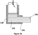
- an extrusion chamber 130 has an L-shape in transverse section, rather than being a straight cylinder. In this manner, the billet 132 is forced along a straight section 134 to form the straight extrudate 136.
- the straight section 134 is of sufficient length to ensure that the extrudate 136 is formed in a straight manner.
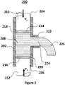
- FIG. 2 shows an extrusion apparatus 200 according to the present disclosure.
- a cylindrical extrusion chamber 202 has two open ends 204 and 206.
- a hot or cold billet 208 is placed into the extrusion chamber 202 from the first open end 204 and/or the second open end 206.
- an aluminium alloy billet may be pre-heated to 350-550°C for warm or hot extrusion or remain unheated for cold extrusion.
- a first punch 210 is positioned at the first open end 204.
- a second punch 212 is positioned at the second open end 206.
- the respective working faces 214 and 216 of the first and second punches 210 and 212 are protected by respective dummy blocks 218 and 220.
- An extrusion die 222 with a designed orifice 224 is installed in the side wall of the extrusion chamber 202.
- the first punch 210 together with dummy block 218 act as a first compression element and the second punch 212 together with dummy clock 220 act as a second compression element.
- the first and second compression elements are independently movable relative to the extrusion chamber 202. As described below, this allows the profile of an extrudate to be controlled, particularly with respect to its curvature.
- the rate of mass flow provided by each of the compression elements can be adjusted.
- the velocities of the punches 210 and 212 can be adjusted to provide a curved extrudate.
- a flow velocity gradient is produced across the die orifice 224. Therefore, the extruded profile bends towards the side of the extrusion chamber 202 which has the lower extrusion velocity.
- the velocity v 1 of the first punch 210 is larger than the velocity v 2 of the second punch 212. Therefore, the extrudate 226 bends towards the second open end 206.
- S is the cross-sectional area
- v is the velocity. Therefore, increasing the velocity v 1 and/or the area of the first dummy block 218 can lead to more material flowing into the upper side of the die exit 222 compared with the lower side.
- the curvature of the extrudate 226 can be adjusted. If the velocity ratio is defined as v 2 /v 1 , a lower velocity ratio tends to increase the material flow velocity gradient at the die exit and lead to greater curvature. When this velocity ratio is less than 1/3, bending curvature increases significantly with reducing velocity ratio. Maximum curvature results at zero velocity of the lower punch 212. The velocity ratio could be changed during extrusion. This will enable the curvature of the extrudate 226 to be changed as extrusion proceeds, which allows more complex extrusions.
- an extrusion ratio is defined as the ratio of the cross-sectional area of the billet to the cross-sectional area of the extruded profile. These areas are controlled by adjusting the cross-sectional area of the extrusion chamber 202 and the extrusion orifice 224 respectively.
- the extrusion ratio can be defined as the square of the diameter ratio of the extrusion chamber 202 to the orifice 224.
- a tubular circular extrusion (a hollow bar) it can be defined as D 1 2 /( D 2 2 - D 3 2 ), where D 1 , D 2 , D 3 are the respective diameters of the extrusion chamber 202, the orifice 224 and a mandrel fixed to the inner wall of the extrusion chamber opposite to the exit die to define the wall thickness of the tube.
- a larger extrusion ratio tends to increase the material flow velocity gradient at the die exit and lead to greater curvature.
- the curvature of the extrudate 226 is increased as the diameter of the orifice 224 is decreased. Conversely, the curvature of the extrudate 226 is reduced as the diameter orifice 224 is increased.
- the effect of changing the extrusion ratio is less than that of changing the velocity ratio, especially when velocity ratio is greater than 0.5. Below this value, the effect of extrusion ratio increases as velocity ratio v 2 /v 1 decreases.
- Figure 3a shows an alternative extrusion apparatus 300 not forming part of the claimed invention.
- the apparatus 300 is similar to the apparatus 100 of Figure 1a , except that two adjacent punches are used instead of a single punch.
- a cylindrical extrusion chamber 302 has two open ends 304 and 306.
- a hot or cold billet 308 is placed into the extrusion chamber 302 from the second open end 306.
- First and second punches 310 and 312 are positioned adjacent to one another at the second open end 306.
- the respective working faces 314 and 316 of the first and second punches 310 and 312 are protected by a respective dummy blocks 318 and 320.
- An extrusion die 322 with a designed orifice 324 is installed at the first open end 304.
- the length of the first dummy block 318 is shown as longer than that of the second dummy block 320.
- the second dummy block 320 may entirely pass the first dummy block 318.
- the billet 308 may flow out of the chamber 302 from the gap between the first dummy block 318 and the second dummy block 320.
- Figure 4 shows yet another alternative extrusion apparatus 400 according to the present disclosure.
- the apparatus comprises a Y-shaped extrusion chamber 402, having a first bore 404, a second bore 405 and a central container 406.
- the first bore 404 and the second bore 405 are positioned at an angle to each other and converge to meet the central container 406, forming the Y-shape.
- Each of the first bore 404, the second bore 405 and the central container 406 has an open end opposite to the point of convergence.
- a first hot or cold billet 407 is placed into the open end of the first bore 404.
- a second hot or cold billet 408 is placed into the open end of the second bore 405.
- a first punch 410 is positioned at the open end of the first bore 404.
- a second punch 412 is positioned at the open end of the second bore 405.
- the respective working faces 414 and 416 of the first and second punches 410 and 412 are protected by a respective dummy block 418 and 420.
- An extrusion die 422 with a designed orifice 424 is installed at the open end of the central container 406.
- the extruded profile bends towards the side of the extrusion chamber 402 which has the lower extrusion velocity.
- the velocity v 1 of the first punch 410 is larger than the velocity v 2 of the second punch 412. Therefore, the extrudate 426 bends towards the second bore 405.
- the areas of the dummy blocks 418 and 420 may be adjusted to provide this effect.
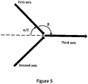
- the first and second compression elements can be positioned at an angle ⁇ , shown in Figure 5 .
- the first and second axes correspond to the first and second compression elements, with the third axis bisecting the first and second axes and corresponding to the direction of extrusion from the die orifice.
- the plane of the cross-section of the extrusion orifice is perpendicular to a line bisecting the first and second axes, with the third axis being parallel to this line.
- a shear stress can be exerted while the billet passes from the entrance to the extrusion chamber to the exit from the extrusion chamber.
- the shear stress exerted at the intersection between the first axis and the third axis (and likewise at the intersection between the second axis and the third axis) causes severe plastic deformation (SPD) of the billet at the point of intersection of the axes.
- SPD of the billet results in an extruded profile with an ultra-fine grain size, thereby improving the mechanical properties of the extruded profile.
- SPD of the billet increases as the angle ⁇ decreases (i.e. as angle ⁇ increases), thereby giving rise to improved mechanical properties arising from SPD with reduced angle ⁇ .
- the first and second axes may be orientated at an angle 0° ⁇ ⁇ ⁇ 360°.
- the extrusion apparatus schematically illustrated in Figure 4 may have any arbitrary angle between 0° and 360°.
- curved sections with undistorted cross-sections can be achieved by utilising asymmetric flow in the extrusion die. Since it is a natural bending process based on internal differential material flow rather than external bending force, defects such as distortion and thinning of the cross-section are avoided. The combination of the extrusion and bending processes into a single process, thus eschews the complication of an extra external bending apparatus.
- the compression elements may move at the same velocity, with the velocity gradient across the extrusion orifice being a function of geometric features (such as a greater surface area for one dummy block/compression element in comparison with the other).
- a combination of geometric features and the velocities of the compression elements may result in a desired velocity gradient at the extrusion orifice.
- a guide external to the die orifice 224, 324, 424 may be employed to ensure precise curve accuracy.
- Any of the above embodiments may be used for extrusion of solid bars or tubes.
- a mandrel may be fixed to the inner wall of the extrusion chamber opposite to the exit die.
- the size of the mandrel relative to the size of the die orifice will define the wall thickness of the extruded tube.
- the curvature of the tube is reduced with increase of wall thickness of the tube.
- the effect of the wall thickness on curvature is small, compared with that of the velocity ratio. Otherwise, a similar tendency in the extrusion of round bars described before also occurs in extrusion of round tubes.
- any of the above embodiments may be used to produce curved profiles in any material that can be manufactured by the conventional extrusion procedure.
- the principal application is extrusion of metal alloys. These include aluminium, magnesium, copper, steel, titanium and nickel.
- the system has been described with reference to aluminium since this is where the most commercially feasible applications are likely to be, but the implementation is not exclusively related to aluminium.
- the hot metal billet used can be virtually any metal alloy billet which is heated to the temperature generally used in the hot extrusion process.
- a True Temperature Technology (3T) facility is utilized to record exit temperature of the extruded part. By adjusting the extrusion velocities of the two punches while keeping the extrusion velocity ratio constant, exit temperature is maintained at a reasonable temperature where solution heat treatment (SHT) takes place.
- SHT solution heat treatment
- the target exit temperature for an extruded part is dependent on the metal alloy.
- temperatures within a range of 500-530°C for solution heat treatment should be realised at the die exit to achieve optimal mechanical properties.
- the extruded part can be quenched after SHT using water, mist spray or air cooling, depending on the alloy and the final mechanical property requirements.
Landscapes
- Engineering & Computer Science (AREA)
- Mechanical Engineering (AREA)
- Extrusion Of Metal (AREA)
- Extrusion Moulding Of Plastics Or The Like (AREA)
Description
- This disclosure relates to a method and equipment for forming curved metal alloy profiles and more particularly aluminium alloy profiles with predesigned curvature in one extrusion-bending process.
- Reducing the weight of metal components used in land, sea and air conveyances leads to a reduction of fuel consumption and therefore a decrease of CO2 emissions. Aluminium alloy profiles are extensively used as construction elements in industrial manufacturing for the production of ultra-light component structures with a high contour complexity, including seat rails, stringers, and frames in the aircraft industry as well as window frames and roof rails in the automotive industry. This is mainly because they facilitate construction of lightweight, strong, and stiff structures. Taking into account the demand for reduced aerodynamic resistance as well as improved aesthetics, the manufacture and application of highly precise curved aluminium alloy profiles with well adapted properties are quite necessary.
- There are several widely acknowledged methods for curving aluminium alloy profiles. Normally they start with manufacturing straight profiles by shape rolling or extrusion, followed by the subsequent secondary bending process such as stretch bending, rotary draw bending, press bending, or roll bending (three-, four-, and six-roll-bending). However, these procedures have disadvantages since: (i) more than one process is needed to achieve the profiles with desired curvature, which greatly decreases manufacturing productivity; (ii) spring-back and cross-sectional deformations usually occur due to the high external bending strain applied in the second bending process; (iii) for hollow sections various fillers and mandrels are used in the secondary bending process to avoid the potential cross-sectional deformation and buckling; (iv) due to the high forces needed for bending profiles, heavy machines are required; and (v) many hollow profiles cannot be bent if the shell is too thin or the curvature is too high.
- The challenge to improved production is to manufacture curved profiles with precise curvature, non-distorted cross-sections and well-defined properties at increased productivity.
-
US 2004/074275 describes an extru-bending machine that can bend a product by extruding two or more hot metal billets with the machine which consists of an extrusion die holder equipped with conical dies, a container holder heating a two or more-holed container with a conical plug, two or more extrusion stems, a hydraulic power system unit, a relative velocity control unit, and a support frame structure. The machine is characterized that, when two or more hot metal billets are welded together inside a conical die cavity and extruded to one product at the die exit, the extru-bending machine can bend the extruded part simultaneously during extruding with a gradient of extrusion velocity on the die's exit owing to the relative moving velocity of two or more extrusion stems. -
SU 837435 claims 1 and 11, describes carrying out extrusion with the simultaneous application of two forces with different speeds to a workpiece, that are directed perpendicular to a side surface of the workpiece on both sides of an extruded profile. -
US 368,314 describes a machine for making curved tubes and pipes. The machine comprises a combination of two parallel or substantially parallel pistons, with a receiver for holding the plastic metal or material, a die secured to the receiver, and means for simultaneously and independently actuating the parallel pistons with reference to the die. -
US 2016/114367 describes a container for use in a metal extrusion press. The container comprises a mantle having an elongate axial bore therein, the bore having a first transverse axis orthogonal to a second transverse axis, and a plurality of longitudinally extending heating elements accommodated by the mantle adjacent the bore. The heating elements are individually controllable for controlling a thermal profile within the container. The container also comprises a plurality of temperature sensors configured to measure the thermal profile within the container. The temperature sensors comprise a first temperature sensor and a second temperature sensor positioned on opposite sides of the first transverse axis, and a third temperature sensor and a fourth temperature sensor positioned on opposite sides of the second transverse axis. -
GB 1442786 - In accordance with a first aspect of the disclosure, there is provided a method of extruding a material, comprising: providing the material into an extrusion chamber of an extrusion apparatus, wherein the extrusion chamber comprises an extrusion orifice and the extrusion apparatus comprises a first compression element and a second compression element in communication with the interior of the extrusion chamber, the first and second compression elements being independently movable relative to the extrusion chamber; moving the first and second compression elements to compress the material within the extrusion chamber and cause a velocity gradient in the extrusion material across the extrusion orifice; and extruding the material through the extrusion orifice such that the velocity gradient forms an extrudate with a curved profile; wherein moving the first compression element and the second compression element comprises moving the first compression element and the second compression element at different speeds along a common axis, wherein moving the first compression element and the second compression element at different speeds along the common axis comprises moving the first compression element and the second compression element towards each other in opposite directions along the common axis.
- According to the first aspect, the plane of the cross-section of the extrusion orifice may be parallel to the common axis such that extruding the material through the extrusion orifice comprises extruding the material through the extrusion orifice substantially perpendicular to the common axis.
- In accordance with a second aspect of the present disclosure, there is provided a method of extruding a material, comprising: providing the material into an extrusion chamber of an extrusion apparatus, wherein the extrusion chamber is a Y-shaped extrusion chamber comprising a first bore, a second bore and a central container, wherein the first bore and the second bore are positioned at an angle to each other and converge to meet the central container, and wherein each of the first bore, the second bore and the central container has an open end opposite to the point of convergence; wherein providing the material into the extrusion chamber comprises placing a first hot or cold billet into the open end of the first bore and placing a second hot or cold billet into the open end of the second bore; wherein the extrusion apparatus further comprises an extrusion die installed at the open end of the central container, the extrusion die comprising an extrusion orifice; and wherein the extrusion apparatus comprises a first compression element and a second compression element, wherein the first and second compression elements are in communication with the interior of the extrusion chamber, the first compression element being movable within the first bore relative to the extrusion chamber and the second compression element being independently movable within the second bore relative to the extrusion chamber; moving the first and second compression elements to compress the material within the extrusion chamber and cause a velocity gradient in the extrusion material across the extrusion orifice; and extruding the material through the extrusion orifice such that the velocity gradient forms an extrudate with a curved profile.
- According to the second aspect, moving the first and second compression elements may comprise moving the first compression element along a first axis and moving the second compression element along a second axis different to the first axis. The first axis and the second axis may be at an angle to one another. The plane of the cross-section of the extrusion orifice may be perpendicular to a line that bisects the first and second axes such that extruding the material through the extrusion orifice comprises extruding the material through the extrusion orifice substantially parallel to the line.
- The method of the second aspect may comprise moving the first compression element and second compression element at different speeds.
- According to the first or second aspects, the first compression element and second compression element may have different cross-sectional areas perpendicular to their direction of movement. The material may be a metal alloy. The metal alloy may be aluminium alloy or magnesium alloy.
- According to the first or second aspects, the method may further comprise providing a guide means adjacent to the extrusion orifice to control curvature of the extruded material. The method may further comprise providing a mandrel in the extrusion chamber opposite to the extrusion orifice. Extruding the material through the extrusion orifice may comprise extruding the material with a hollow cross-section defined by the mandrel and orifice. The plane of the cross-section of the mandrel that defines the hollow cross-section of the extruded material may be parallel to the plane of the cross-section of the extrusion orifice.
- According to the first or second aspects, the method may further comprise preheating the material before providing it into the extrusion chamber. The method may comprise adjusting the speed of the first and second compression elements while keeping the velocity ratio constant, such that the temperature of the extruded material at the exit from the extrusion orifice is maintained at a target temperature at which solution heat treatment, SHT, takes place. The extruded material may be quenched after SHT using water, mist spray or air cooling. The method may further comprise varying the speed of movement of the first compression element and/or the second compression element to vary the velocity ratio as the material is extruded.
- In accordance with a third aspect of the present disclosure, there is provided an apparatus for extrusion of a material, the apparatus comprising: an extrusion chamber for receipt of an extrusion material, the extrusion chamber comprising an extrusion orifice; a first compression element and a second compression element, the first and second compression elements being in communication with the interior of the extrusion chamber and being independently movable relative to the extrusion chamber, wherein: the first and second compression elements are configured to be moved to compress material within the extrusion chamber and cause a velocity gradient in the extrusion material across the extrusion orifice such that the velocity gradient forms an extrudate with a curved profile when material is extruded through the extrusion orifice; and the first compression element and the second compression element are configured to be moved at different speeds along a common axis, wherein the first compression element and the second compression element are configured to be moved towards each other in opposite directions along the common axis
- According to the third aspect, the plane of the cross-section of the extrusion orifice may be parallel to the common axis.
- In accordance with a fourth aspect of the present disclosure, there is provided an apparatus for extrusion of a material, the apparatus comprising: an extrusion chamber for receipt of an extrusion material, wherein the extrusion chamber is a Y-shaped extrusion chamber comprising a first bore, a second bore and a central container, wherein the first bore and the second bore are positioned at an angle to each other and converge to meet the central container, and wherein each of the first bore, the second bore and the central container has an open end opposite to the point of convergence, wherein the extrusion chamber is configured for receipt of a first billet into the open end of the first bore and for receipt of a second billet into the open end of the second bore; an extrusion die installed at the open end of the central container, the extrusion die comprising an extrusion orifice; a first compression element and a second compression element, the first and second compression elements being in communication with the interior of the extrusion chamber, the first compression element being movable within the first bore relative to the extrusion chamber and the second compression element being independently movable within the second bore relative to the extrusion chamber, wherein the first and second compression elements are configured to be moved to compress material within the extrusion chamber and cause a velocity gradient in the extrusion material across the extrusion orifice such that the velocity gradient forms an extrudate with a curved profile when material is extruded through the extrusion orifice.
- According to the fourth aspect, the first compression element may be configured to be moved along a first axis and the second compression element may be configured to be moved along a second axis different to the first axis. The first axis and the second axis may be at an angle to one another. The plane of the cross-section of the extrusion orifice may be perpendicular to a line that bisects the first and second axes.
- According to the third or fourth aspects, the first compression element and second compression element may be configured to be moved simultaneously. The first compression element and second compression element may be configured to be moved at different speeds. The first compression element and second compression element may have different cross-sectional areas perpendicular to their direction of movement.
- The extrusion material may be a metal alloy. The metal alloy may be aluminium alloy or magnesium alloy. The extrusion orifice may be provided by an extrusion die that defines the geometry of the orifice.
- According to the third or fourth aspects, the apparatus may further comprise a guide means adjacent to the extrusion orifice to control curvature of the extruded material. The apparatus may further comprise a mandrel in the extrusion chamber opposite to the extrusion orifice.
- The extrusion material may be preheated. The extrusion chamber may be cylindrical. The cross-sectional area of the extrusion chamber may be larger than the cross-sectional area of the extrusion orifice.
- According to the third or fourth aspects, the first compression element and/or the second compression element may be configured to be moved at varying speed.
- According to the present disclosure, there is provided a method of forming curved metal alloy profiles comprising:
- (i) providing the sideways extrusion setup, forward extrusion setup or angled extrusion setup;
- (ii) pre-heating a metal alloy billet before transferring it to an extrusion container for hot extrusion; or directly transferring the unheated metal alloy billet to the extrusion container for cold extrusion;
- (iii) applying pressure to the two dummy blocks through the corresponding two punches simultaneously, the metal alloy billet is pressed against the extrusion die and squeezed through the die opening; and
- (iv) adjusting the velocities of the two punches so as to form a velocity gradient across the die orifice and produce a curved profile of the long extruded section.
- This has the following advantages:
- (i) forming curved profiles without defects such as distortion or thinning of the cross-section, spring-back, wrinkling and folding. Bending is intrinsic to the process, based on internal differential material flow, rather than external bending force;
- (ii) forming profiles with ultra-fine grain size for cold extrusion and therefore improved mechanical properties due to severe plastic deformation (SPD) caused by shear stresses in the intersecting deformation zone of the container;
- (iii) forming profiles with adjustable arbitrary curvatures in one extrusion-bending procedure, which greatly increases the manufacturing efficiency; and
- (iv) no fillers or extra heavy machines are needed for the bending process, which greatly reduces the production cost.
- Exemplary embodiments of the disclosure shall now be described with reference to the drawings in which:
-
Figure 1a is a schematic illustration of an extrusion apparatus known in the art; -
Figure 1b is a schematic illustration of another extrusion apparatus known in the art; -
Figure 2 is a schematic illustration of an extrusion apparatus according to an embodiment; -
Figure 3a is a schematic illustration of another extrusion apparatus not forming part of the invention; -
Figure 3b is a cross-section through the line m-m inFigure 3a ; -
Figure 4 is a schematic illustration of yet another extrusion apparatus according to an embodiment; -
Figure 5 is a schematic illustration of the orientation of a first, second and third axis of an extrusion apparatus according to an embodiment. - Throughout the description and the drawings, like reference numerals refer to like parts.
-
Figure 1a shows an extrusion apparatus known in the art. Acylindrical extrusion chamber 102 has twoopen ends orifice 110 is installed at the firstopen end 104. The geometry of theorifice 110 is designed to form the extruded material into a chosen shape. A hot orcold billet 112 is placed into theextrusion chamber 102 from the secondopen end 106. - A
punch 114 is positioned at the secondopen end 106. Its workingface 116 would usually be protected by adummy block 118. Thepunch 114, together withdummy block 118, acts as a compression element and moves along theextrusion chamber 102 at a velocity v1, forcing thebillet 112 through thedie orifice 110, producing astraight extrudate 120. - Another extrusion apparatus known in the art is shown in
Figure 1b . In this case, anextrusion chamber 130 has an L-shape in transverse section, rather than being a straight cylinder. In this manner, thebillet 132 is forced along astraight section 134 to form thestraight extrudate 136. Thestraight section 134 is of sufficient length to ensure that theextrudate 136 is formed in a straight manner. - Once the
straight extrudate -
Figure 2 shows anextrusion apparatus 200 according to the present disclosure. Acylindrical extrusion chamber 202 has twoopen ends cold billet 208 is placed into theextrusion chamber 202 from the firstopen end 204 and/or the secondopen end 206. For example, an aluminium alloy billet may be pre-heated to 350-550°C for warm or hot extrusion or remain unheated for cold extrusion. Afirst punch 210 is positioned at the firstopen end 204. Asecond punch 212 is positioned at the secondopen end 206. The respective working faces 214 and 216 of the first andsecond punches orifice 224 is installed in the side wall of theextrusion chamber 202. - The
first punch 210 together withdummy block 218 act as a first compression element and thesecond punch 212 together withdummy clock 220 act as a second compression element. The skilled person with recognise that these compression elements could be replaced by any other suitable compression means. The first and second compression elements are independently movable relative to theextrusion chamber 202. As described below, this allows the profile of an extrudate to be controlled, particularly with respect to its curvature. - In operation, pressure is applied to the two
dummy blocks punches first punch 210 is v1, and the velocity of thesecond punch 212 is v2. As the punches move towards each other, thebillet 208 is forced sideways out of theextrusion chamber 202 through thedie orifice 224. Its exiting direction is perpendicular to the punch motion direction. - To produce a curved extrudate, the rate of mass flow provided by each of the compression elements can be adjusted. In one embodiment, the velocities of the
punches die orifice 224. Therefore, the extruded profile bends towards the side of theextrusion chamber 202 which has the lower extrusion velocity. InFigure 2 , the velocity v1 of thefirst punch 210 is larger than the velocity v2 of thesecond punch 212. Therefore, theextrudate 226 bends towards the secondopen end 206. In another embodiment, the area of thefirst dummy block 218 is greater than that of thesecond dummy block 220. In this instance, the extruded profile will bend downwards as shown inFig. 2 even when v1=v2. - The essence is to control the volume of material flowing into the
die exit 222 per unit time, which can be expressed as Q=Sv. Here S is the cross-sectional area and v is the velocity. Therefore, increasing the velocity v1 and/or the area of thefirst dummy block 218 can lead to more material flowing into the upper side of thedie exit 222 compared with the lower side. - By creating a controlled gradient of flow velocity across the exit of an extrusion die orifice utilizing two extrusion punches, the extrusion and bending operations are performed simultaneously. This removes the need for post-processing of straight extruded pieces to provide curvature, and overcomes the issues mentioned above.
- By adjusting the ratio of the velocities of the two punches (or more generally the rate of material flow Q), the curvature of the
extrudate 226 can be adjusted. If the velocity ratio is defined as v2/v1, a lower velocity ratio tends to increase the material flow velocity gradient at the die exit and lead to greater curvature. When this velocity ratio is less than 1/3, bending curvature increases significantly with reducing velocity ratio. Maximum curvature results at zero velocity of thelower punch 212. The velocity ratio could be changed during extrusion. This will enable the curvature of theextrudate 226 to be changed as extrusion proceeds, which allows more complex extrusions. Additionally, the relative cross-sectional areas of theextrusion chamber 202 and theorifice 224 can be adjusted to change the curvature. An extrusion ratio is defined as the ratio of the cross-sectional area of the billet to the cross-sectional area of the extruded profile. These areas are controlled by adjusting the cross-sectional area of theextrusion chamber 202 and theextrusion orifice 224 respectively. For solid circular bar extrusion, the extrusion ratio can be defined as the square of the diameter ratio of theextrusion chamber 202 to theorifice 224. For a tubular circular extrusion (a hollow bar), it can be defined as D 1 2/( D 2 2-D 3 2), where D 1, D 2, D 3 are the respective diameters of theextrusion chamber 202, theorifice 224 and a mandrel fixed to the inner wall of the extrusion chamber opposite to the exit die to define the wall thickness of the tube. - A larger extrusion ratio tends to increase the material flow velocity gradient at the die exit and lead to greater curvature. For a constant diameter of the
extrusion chamber 202, the curvature of theextrudate 226 is increased as the diameter of theorifice 224 is decreased. Conversely, the curvature of theextrudate 226 is reduced as thediameter orifice 224 is increased. The effect of changing the extrusion ratio is less than that of changing the velocity ratio, especially when velocity ratio is greater than 0.5. Below this value, the effect of extrusion ratio increases as velocity ratio v2/v1 decreases. -
Figure 3a shows analternative extrusion apparatus 300 not forming part of the claimed invention. - The
apparatus 300 is similar to theapparatus 100 ofFigure 1a , except that two adjacent punches are used instead of a single punch. Acylindrical extrusion chamber 302 has twoopen ends cold billet 308 is placed into theextrusion chamber 302 from the secondopen end 306. First andsecond punches open end 306. The respective working faces 314 and 316 of the first andsecond punches orifice 324 is installed at the firstopen end 304. - The length of the
first dummy block 318 is shown as longer than that of thesecond dummy block 320. In the case that the second dummy block 320 moves faster than thefirst dummy block 318, then thesecond dummy block 320 may entirely pass thefirst dummy block 318. In this case, thebillet 308 may flow out of thechamber 302 from the gap between thefirst dummy block 318 and thesecond dummy block 320. By implementing a longer profile of the first dummy block, this situation is mitigated. - In operation, pressure is applied to the two
dummy blocks punches first punch 310 is v1, and the velocity of thesecond punch 312 is v2. As the punches move alongside each other, thebillet 308 is forced out of theextrusion chamber 302 through thedie orifice 324. - As in the above embodiment, when one punch is moved faster than the other, a flow velocity gradient is produced across the
die orifice 324. Therefore, the extruded profile bends towards the side of theextrusion chamber 302 which has the lower extrusion velocity. InFigure 3a , the velocity v1 of thefirst punch 310 is larger than the velocity v2 of thesecond punch 312. Therefore, theextrudate 326 bends towards the side of thecylindrical extrusion chamber 302 with thesecond punch 312. Additionally or alternatively, the areas of the dummy blocks 318 and 320 may be adjusted to provide this effect.Figure 3b shows the dummy blocks 318 and 320 with different cross-sectional areas perpendicular to their direction of movement. -
Figure 4 shows yet anotheralternative extrusion apparatus 400 according to the present disclosure. The apparatus comprises a Y-shapedextrusion chamber 402, having afirst bore 404, asecond bore 405 and acentral container 406. Thefirst bore 404 and thesecond bore 405 are positioned at an angle to each other and converge to meet thecentral container 406, forming the Y-shape. Each of thefirst bore 404, thesecond bore 405 and thecentral container 406 has an open end opposite to the point of convergence. - A first hot or
cold billet 407 is placed into the open end of thefirst bore 404. A second hot orcold billet 408 is placed into the open end of thesecond bore 405. Afirst punch 410 is positioned at the open end of thefirst bore 404. Asecond punch 412 is positioned at the open end of thesecond bore 405. The respective working faces 414 and 416 of the first andsecond punches orifice 424 is installed at the open end of thecentral container 406. - In operation, pressure is applied to the two
dummy blocks punches first punch 410 is v1, and the velocity of thesecond punch 412 is v2. As the punches move towards each other, thebillet 408 is forced sideways out of theextrusion chamber 402 through thedie orifice 424. - As in the above embodiments, when one punch is moved faster than the other, a flow velocity gradient is produced across the
die orifice 424. Therefore, the extruded profile bends towards the side of theextrusion chamber 402 which has the lower extrusion velocity. InFigure 4 , the velocity v1 of thefirst punch 410 is larger than the velocity v2 of thesecond punch 412. Therefore, theextrudate 426 bends towards thesecond bore 405. Additionally or alternatively, the areas of the dummy blocks 418 and 420 may be adjusted to provide this effect. - In the embodiments described above with reference to
Figures 2 to 4 , the first and second compression elements can be positioned at an angle α, shown inFigure 5 . InFigure 5 , the first and second axes correspond to the first and second compression elements, with the third axis bisecting the first and second axes and corresponding to the direction of extrusion from the die orifice. Hence, the plane of the cross-section of the extrusion orifice is perpendicular to a line bisecting the first and second axes, with the third axis being parallel to this line. - The first axis is at an angle of β = 180° - α /2 to the direction of flow of the extrudate from the extrusion apparatus (i.e. the third axis). Likewise, the second axis is at an angle of β = 180° - α /2 to the third axis.
- By having an angle of β < 180°, a shear stress can be exerted while the billet passes from the entrance to the extrusion chamber to the exit from the extrusion chamber. The shear stress exerted at the intersection between the first axis and the third axis (and likewise at the intersection between the second axis and the third axis) causes severe plastic deformation (SPD) of the billet at the point of intersection of the axes. SPD of the billet results in an extruded profile with an ultra-fine grain size, thereby improving the mechanical properties of the extruded profile. SPD of the billet increases as the angle β decreases (i.e. as angle α increases), thereby giving rise to improved mechanical properties arising from SPD with reduced angle β.
- The first and second axes may be orientated at an angle 0° ≤ α ≤ 360°. The extrusion apparatus schematically illustrated in
Figure 2 corresponds to an angle of α = 180°. The extrusion apparatus schematically illustrated inFigure 3 corresponds to an angle of α = 0°. The extrusion apparatus schematically illustrated inFigure 4 may have any arbitrary angle between 0° and 360°. - By using any of the above embodiments, curved sections with undistorted cross-sections can be achieved by utilising asymmetric flow in the extrusion die. Since it is a natural bending process based on internal differential material flow rather than external bending force, defects such as distortion and thinning of the cross-section are avoided. The combination of the extrusion and bending processes into a single process, thus eschews the complication of an extra external bending apparatus.
- This effect is achieved by variations in velocities v1 and v2 of the compression elements (formed of punches and dummy blocks). However, in some embodiments, the compression elements may move at the same velocity, with the velocity gradient across the extrusion orifice being a function of geometric features (such as a greater surface area for one dummy block/compression element in comparison with the other). In other examples, a combination of geometric features and the velocities of the compression elements may result in a desired velocity gradient at the extrusion orifice.
- In any of the above embodiments, a guide external to the
die orifice - Any of the above embodiments may be used to produce curved profiles in any material that can be manufactured by the conventional extrusion procedure. The principal application is extrusion of metal alloys. These include aluminium, magnesium, copper, steel, titanium and nickel. The system has been described with reference to aluminium since this is where the most commercially feasible applications are likely to be, but the implementation is not exclusively related to aluminium.
- Any of the above embodiments may be used for hot or cold extrusion. In the case of hot extrusion, the hot metal billet used can be virtually any metal alloy billet which is heated to the temperature generally used in the hot extrusion process. A True Temperature Technology (3T) facility is utilized to record exit temperature of the extruded part. By adjusting the extrusion velocities of the two punches while keeping the extrusion velocity ratio constant, exit temperature is maintained at a reasonable temperature where solution heat treatment (SHT) takes place. The target exit temperature for an extruded part is dependent on the metal alloy. For the 6xxx series aluminium alloys, temperatures within a range of 500-530°C for solution heat treatment should be realised at the die exit to achieve optimal mechanical properties. The extruded part can be quenched after SHT using water, mist spray or air cooling, depending on the alloy and the final mechanical property requirements.
- Although the embodiments described in
figures 2 to 5 above comprise two compression elements, it will be understood that further compression elements could be incorporated to control curvature in other planes.
Claims (17)
- A method of extruding a material, comprising:providing the material into an extrusion chamber (202) of an extrusion apparatus (200), wherein the extrusion chamber (202) comprises an extrusion orifice (224) and the extrusion apparatus (200) comprises a first compression element (210) and a second compression element (212) in communication with the interior of the extrusion chamber (202), the first (210) and second (212) compression elements being independently movable relative to the extrusion chamber (202);moving the first (210) and second (212) compression elements to compress the material within the extrusion chamber (202) and cause a velocity gradient in the extrusion material across the extrusion orifice (224); andextruding the material through the extrusion orifice (224) such that the velocity gradient forms an extrudate (226) with a curved profile;characterized in that moving the first compression element (210) and the second compression element (212) comprises moving the first compression element (210) and the second compression element (212) at different speeds along a common axis, wherein moving the first compression element (210) and the second compression element (212) at different speeds along the common axis comprises moving the first compression element (210) and the second compression element (212) towards each other in opposite directions along the common axis
- A method according to claim 1, wherein: the plane of the cross-section of the extrusion orifice (224) is parallel to the common axis such that extruding the material through the extrusion orifice (224) comprises extruding the material through the extrusion orifice (224) substantially perpendicular to the common axis.
- A method of extruding a material, comprising:providing the material into an extrusion chamber (402) of an extrusion apparatus (400),wherein the extrusion chamber is a Y-shaped extrusion chamber (402) comprising a first bore (404), a second bore (405) and a central container (406), wherein the first bore (404) and the second bore (405) are positioned at an angle to each other and converge to meet the central container (406), and wherein each of the first bore (404), the second bore (405) and the central container (406) has an open end opposite to the point of convergence;wherein providing the material into the extrusion chamber (402) comprises placing a first hot or cold billet (407) into the open end of the first bore (404) and placing a second hot or cold billet (408) into the open end of the second bore (405);wherein the extrusion apparatus (400) further comprises an extrusion die (422) installed at the open end of the central container (406), the extrusion die (422) comprising an extrusion orifice (424); andwherein the extrusion apparatus (400) comprises a first compression element (410) and a second compression element (412), wherein the first and second compression elements (410, 412) are in communication with the interior of the extrusion chamber (402), the first compression element (410) being movable within the first bore (404) relative to the extrusion chamber (402) and the second compression element (412) being independently movable within the second bore (405) relative to the extrusion chamber (402);moving the first (410) and second (412) compression elements to compress the material within the extrusion chamber (402) and cause a velocity gradient in the extrusion material across the extrusion orifice (424); andextruding the material through the extrusion orifice (424) such that the velocity gradient forms an extrudate (426) with a curved profile.
- A method according to claim 3, wherein moving the first (410) and second (412) compression elements comprises moving the first compression element (410) along a first axis and moving the second compression element (412) along a second axis different to the first axis, wherein the first axis and the second axis are at an angle to one another, wherein the plane of the cross-section of the extrusion orifice (424) is perpendicular to a line that bisects the first and second axes such that extruding the material through the extrusion orifice (424) comprises extruding the material through the extrusion orifice (424) substantially parallel to the line.
- A method according to claim 3 or claim 4, comprising moving the first compression element and second compression element at different speeds.
- A method according to any one of the preceding claims, wherein the first compression element (210, 410) and second compression element (212, 412) have different cross-sectional areas perpendicular to their direction of movement; and/or
wherein the material is a metal alloy, wherein the metal alloy is optionally aluminium alloy or magnesium alloy. - A method according to any one of the preceding claims, further comprising providing a guide means adjacent to the extrusion orifice (224, 424) to control curvature of the extruded material (226, 426).
- A method according to any one of the preceding claims, further comprising providing a mandrel in the extrusion chamber (202, 402) opposite to the extrusion orifice (224, 424), wherein extruding the material through the extrusion orifice (224, 424) optionally comprises extruding the material with a hollow cross-section defined by the mandrel and orifice (224, 424).
- A method according to any one of the preceding claims, further comprising preheating the material before providing it into the extrusion chamber (202, 402), wherein the method optionally further comprises adjusting the speed of the first (210, 410) and second (212, 412) compression elements while keeping the velocity ratio constant, such that the temperature of the extruded material (226, 426) at the exit from the extrusion orifice (224, 424) is maintained at a target temperature at which solution heat treatment, SHT, takes place, wherein the extruded material (226, 426) is optionally quenched after SHT using water, mist spray or air cooling.
- A method according to claims 1 to 8, further comprising varying the speed of movement of the first compression element (210, 410) and/or the second compression element (212, 412) to vary the velocity ratio as the material is extruded.
- An apparatus (200) for extrusion of a material, the apparatus (200) comprising:an extrusion chamber (202) for receipt of an extrusion material, the extrusion chamber (202) comprising an extrusion orifice (224);a first compression element (210) and a second compression element (212), the first (210) and second (212) compression elements being in communication with the interior of the extrusion chamber (202) and being independently movable relative to the extrusion chamber (202), wherein:the first (210) and second (212) compression elements are configured to be moved to compress material within the extrusion chamber (202) and cause a velocity gradient in the extrusion material across the extrusion orifice (224) such that the velocity gradient forms an extrudate (226) with a curved profile when material is extruded through the extrusion orifice (224); characterized in thatthe first compression element (210) and the second compression element (212) are configured to be moved at different speeds along a common axis, wherein the first compression element (210) and the second compression element (212) are configured to be moved towards each other in opposite directions along the common axis.
- An apparatus (200) according to claim 11, wherein: the plane of the cross-section of the extrusion orifice (224) is parallel to the common axis.
- An apparatus (400) for extrusion of a material, the apparatus (400) comprising:an extrusion chamber (402) for receipt of an extrusion material, wherein the extrusion chamber is a Y-shaped extrusion chamber (402) comprising a first bore (404), a second bore (405) and a central container (406), wherein the first bore (404) and the second bore (405) are positioned at an angle to each other and converge to meet the central container (406), and wherein each of the first bore (404), the second bore (405) and the central container (406) has an open end opposite to the point of convergence, wherein the extrusion chamber (402) is configured for receipt of a first billet (407) into the open end of the first bore (404) and for receipt of a second billet (408) into the open end of the second bore (405);an extrusion die (422) installed at the open end of the central container (406), the extrusion die (422) comprising an extrusion orifice (424);a first compression element (410) and a second compression element (412), the first (410) and second (412) compression elements being in communication with the interior of the extrusion chamber (402), the first compression element (410) being movable within the first bore (404) relative to the extrusion chamber (402) and the second compression element (412) being independently movable within the second bore (405) relative to the extrusion chamber (402),wherein the first (410) and second (412) compression elements are configured to be moved to compress material within the extrusion chamber (402) and cause a velocity gradient in the extrusion material across the extrusion orifice (424) such that the velocity gradient forms an extrudate (426) with a curved profile when material is extruded through the extrusion orifice (424).
- An apparatus (400) according to claim 13, wherein the first compression element (410) is configured to be moved along a first axis and the second compression element (412) is configured to be moved along a second axis different to the first axis, wherein the first axis and the second axis are at an angle to one another, and wherein the plane of the cross-section of the extrusion orifice (424) is perpendicular to a line that bisects the first and second axes.
- An apparatus according to any of claims 11 to 14, wherein the first compression element (210, 410) and second compression element (212, 412) are configured to be moved simultaneously; and, optionally:wherein the first compression element (410) and second compression element (412) are configured to be moved at different speeds; and/orwherein the first compression element (210, 410) and second compression element (212, 412) have different cross-sectional areas perpendicular to their direction of movement.
- An apparatus (200, 400) according to any one of claims 11 to 15, further comprising a guide means adjacent to the extrusion orifice (224, 424) to control curvature of the extruded material (226, 426); and/or further comprising a mandrel in the extrusion chamber (202, 402) opposite to the extrusion orifice (224, 424).
- An apparatus (200, 400) according to any one of claims 11 to 16, wherein the first compression element (210, 410) and/or the second compression element (212, 412) are configured to be moved at a varying speed.
Applications Claiming Priority (2)
| Application Number | Priority Date | Filing Date | Title |
|---|---|---|---|
| GBGB1707519.3A GB201707519D0 (en) | 2017-05-10 | 2017-05-10 | A method for forming curved lengths of extruded profiles/sections in metal alloys |
| PCT/GB2018/051260 WO2018206960A1 (en) | 2017-05-10 | 2018-05-10 | A method for forming curved lengths of extruded profiles/sections in metal alloys |
Publications (2)
| Publication Number | Publication Date |
|---|---|
| EP3621753A1 EP3621753A1 (en) | 2020-03-18 |
| EP3621753B1 true EP3621753B1 (en) | 2022-08-24 |
Family
ID=59065707
Family Applications (1)
| Application Number | Title | Priority Date | Filing Date |
|---|---|---|---|
| EP18725607.8A Active EP3621753B1 (en) | 2017-05-10 | 2018-05-10 | A method for forming curved lengths of extruded profiles/sections in metal alloys |
Country Status (7)
| Country | Link |
|---|---|
| US (1) | US20200206794A1 (en) |
| EP (1) | EP3621753B1 (en) |
| JP (1) | JP7270553B2 (en) |
| KR (1) | KR102449312B1 (en) |
| CN (2) | CN110891703B (en) |
| GB (1) | GB201707519D0 (en) |
| WO (1) | WO2018206960A1 (en) |
Families Citing this family (9)
| Publication number | Priority date | Publication date | Assignee | Title |
|---|---|---|---|---|
| GB2580955B (en) * | 2019-01-31 | 2021-03-10 | Imperial College Innovations Ltd | Apparatus and method for extruding curved profiles |
| CN109967549B (en) * | 2019-04-02 | 2020-04-14 | 山东理工大学 | Profile self-bending extrusion die |
| CN111016258B (en) * | 2019-11-18 | 2020-09-04 | 苏州鸿凌达电子科技有限公司 | Extrusion molding equipment applied to graphene fiber orientation arrangement |
| CN111589889A (en) * | 2020-06-18 | 2020-08-28 | 无锡市源昌机械制造有限公司 | Right-angle metal section bending forming extruder |
| CN111992592B (en) * | 2020-09-07 | 2024-08-09 | 凯维思(山东)智能制造科技有限公司 | Double-flow regulation and control compression forming equipment, system and method |
| CN114632831A (en) * | 2022-04-21 | 2022-06-17 | 凯维思智能装备科技(山东)有限公司 | Multi-shear deformation bending forming device and method |
| CN116020894A (en) * | 2023-03-29 | 2023-04-28 | 太原科技大学 | Die and process for equal-channel, double-rotational, variable-diameter extrusion of ring-shaped parts |
| CN118403913A (en) * | 2024-06-18 | 2024-07-30 | 南京航空航天大学 | A forming method for spatial three-axis differential extrusion |
| CN118417355B (en) * | 2024-06-19 | 2025-10-03 | 南京航空航天大学 | A differential extrusion coupled secondary correction integrated forming method for complex profile components with variable curvature |
Family Cites Families (14)
| Publication number | Priority date | Publication date | Assignee | Title |
|---|---|---|---|---|
| US368314A (en) * | 1887-08-16 | whitney | ||
| US3286502A (en) * | 1964-03-26 | 1966-11-22 | Gen Electric | Side extrusion |
| NO129892B (en) * | 1972-12-01 | 1974-06-10 | Graenges Essem Plast As | |
| DE2855449A1 (en) * | 1978-12-21 | 1980-07-03 | Vitkovice Zelezarny | Extrusion of pipe bends and elbows - by means of die with eccentric hole and eccentrically mounted mandrel |
| SU837435A1 (en) * | 1979-07-24 | 1981-06-15 | Всесоюзный Заочный Машиностроитель-Ный Институт | Bent section production method |
| DE3706193A1 (en) * | 1987-02-26 | 1988-09-08 | Langenstein & Schemann Gmbh | HYDRAULIC COLD FLOW PRESS |
| DE19716292C2 (en) * | 1997-04-18 | 2001-02-01 | Daimler Chrysler Ag | Extrusion device |
| KR100416578B1 (en) * | 2000-11-01 | 2004-02-05 | 진인태 | Bending Machine by Hot Metal Extrusion |
| JP3942873B2 (en) * | 2000-12-22 | 2007-07-11 | 株式会社小松製作所 | Extrusion processing apparatus and extrusion processing method |
| WO2005007317A1 (en) * | 2003-07-22 | 2005-01-27 | Katsuaki Nakamura | Metal molding method and machine, and metal molded body |
| JP3956919B2 (en) * | 2003-08-20 | 2007-08-08 | ヤマハ株式会社 | Peltier module manufacturing method |
| US10434553B2 (en) * | 2014-10-27 | 2019-10-08 | Exco Technologies Limited | Extrusion press container and mantle for same, and method |
| CN104550289B (en) * | 2014-12-30 | 2018-08-28 | 天津理工大学 | The method of extrusion forming curvature of space tubing of more punch-pin |
| CN104772358B (en) * | 2015-04-28 | 2017-03-29 | 哈尔滨理工大学 | Metal replaces extrusion molding apparatus and method |
-
2017
- 2017-05-10 GB GBGB1707519.3A patent/GB201707519D0/en not_active Ceased
-
2018
- 2018-05-10 WO PCT/GB2018/051260 patent/WO2018206960A1/en not_active Ceased
- 2018-05-10 KR KR1020197036499A patent/KR102449312B1/en active Active
- 2018-05-10 CN CN201880046445.XA patent/CN110891703B/en active Active
- 2018-05-10 US US16/612,232 patent/US20200206794A1/en not_active Abandoned
- 2018-05-10 CN CN202210474856.7A patent/CN114682639B/en active Active
- 2018-05-10 JP JP2019561951A patent/JP7270553B2/en active Active
- 2018-05-10 EP EP18725607.8A patent/EP3621753B1/en active Active
Also Published As
| Publication number | Publication date |
|---|---|
| CN114682639A (en) | 2022-07-01 |
| CN110891703A (en) | 2020-03-17 |
| KR20200005643A (en) | 2020-01-15 |
| WO2018206960A1 (en) | 2018-11-15 |
| US20200206794A1 (en) | 2020-07-02 |
| EP3621753A1 (en) | 2020-03-18 |
| GB201707519D0 (en) | 2017-06-21 |
| KR102449312B1 (en) | 2022-09-29 |
| JP7270553B2 (en) | 2023-05-10 |
| CN110891703B (en) | 2022-05-24 |
| JP2020519447A (en) | 2020-07-02 |
| CN114682639B (en) | 2024-08-27 |
Similar Documents
| Publication | Publication Date | Title |
|---|---|---|
| US20200206794A1 (en) | A method for forming curved lengths of extruded profiles/sections in metal alloys | |
| CN101406906A (en) | Method for preparing magnesium alloy section bar by continuous corner shearing and squeezing shaping and mold | |
| CN113976789B (en) | A hollow diameter reduction extrusion forming process for a titanium alloy thin-walled super-large cone angle special-shaped ring forging with an inner and outer flange structure | |
| CN103302125A (en) | On-line bending and forming device of three-dimensional variable-radian extrusion profile | |
| CN108097733B (en) | A extrusion-twisting compound processing die and method capable of realizing multi-directional shearing | |
| CN107234443A (en) | The three-dimensional online pane bending apparatus of variable curvature section bar that robot is actively drawn | |
| CN106670249A (en) | Extruding-expanding molding method for rim provided with flange | |
| Zhou et al. | A novel application of sideways extrusion to produce curved aluminium profiles: Feasibility study | |
| CN116393515A (en) | Continuous rolling equipment and method for thermal controllable interface of seamless metal composite pipe | |
| US20040074275A1 (en) | Hot metal extru-bending machine | |
| WO2002024366A1 (en) | Method of forming cold diametrally reducing roll for metal pipe and metal pipe formed by the method | |
| CA2952090C (en) | Method and system for producing open or closed annular structural components made of light metal and alloys thereof | |
| US20240342779A1 (en) | Apparatus and method for extruding wide profiles | |
| KR20210018335A (en) | Equipment for producing metal sheets or hollow chamber plates from extrusion profiles | |
| KR20160140785A (en) | Method and device for processing extruded profile segments composed of magnesium or magnesium alloys and a lightweight construction element produced therefrom | |
| Zhou et al. | Advances and Trends in Forming Curved Extrusion Profiles. Materials 2021, 14, 1603 | |
| CN112475298A (en) | Metal powder continuous forming device and method | |
| CN106334716B (en) | Flow controls the mould and its application method of formula one-shot forming various dimensions elbow member | |
| CN112439789A (en) | Forming method of easy-to-demould core rod and metal composite pipe | |
| Chatti et al. | Manufacturing of profiles for lightweight structures | |
| CN105344739B (en) | A kind of continuous casting forging molding technique of band extruding plastotype | |
| RU2686704C1 (en) | Method of producing long-axis articles | |
| CN119910047A (en) | A method and device for strong shear extrusion forming of annular cylindrical parts | |
| JPS62263822A (en) | Extrusion forming method for hollow or semi-hollow stock and extrusion forming metal die for extrusion forming | |
| CN118403913A (en) | A forming method for spatial three-axis differential extrusion |
Legal Events
| Date | Code | Title | Description |
|---|---|---|---|
| STAA | Information on the status of an ep patent application or granted ep patent |
Free format text: STATUS: UNKNOWN |
|
| STAA | Information on the status of an ep patent application or granted ep patent |
Free format text: STATUS: THE INTERNATIONAL PUBLICATION HAS BEEN MADE |
|
| PUAI | Public reference made under article 153(3) epc to a published international application that has entered the european phase |
Free format text: ORIGINAL CODE: 0009012 |
|
| STAA | Information on the status of an ep patent application or granted ep patent |
Free format text: STATUS: REQUEST FOR EXAMINATION WAS MADE |
|
| 17P | Request for examination filed |
Effective date: 20191204 |
|
| AK | Designated contracting states |
Kind code of ref document: A1 Designated state(s): AL AT BE BG CH CY CZ DE DK EE ES FI FR GB GR HR HU IE IS IT LI LT LU LV MC MK MT NL NO PL PT RO RS SE SI SK SM TR |
|
| AX | Request for extension of the european patent |
Extension state: BA ME |
|
| DAV | Request for validation of the european patent (deleted) | ||
| DAX | Request for extension of the european patent (deleted) | ||
| STAA | Information on the status of an ep patent application or granted ep patent |
Free format text: STATUS: EXAMINATION IS IN PROGRESS |
|
| 17Q | First examination report despatched |
Effective date: 20201216 |
|
| RAP1 | Party data changed (applicant data changed or rights of an application transferred) |
Owner name: IMPERIAL COLLEGE INNOVATIONS LIMITED |
|
| REG | Reference to a national code |
Ref country code: DE Ref legal event code: R079 Ref document number: 602018039692 Country of ref document: DE Free format text: PREVIOUS MAIN CLASS: B21C0023000000 Ipc: B29C0048130000 |
|
| GRAP | Despatch of communication of intention to grant a patent |
Free format text: ORIGINAL CODE: EPIDOSNIGR1 |
|
| STAA | Information on the status of an ep patent application or granted ep patent |
Free format text: STATUS: GRANT OF PATENT IS INTENDED |
|
| RIC1 | Information provided on ipc code assigned before grant |
Ipc: B29C 48/48 20190101ALI20220215BHEP Ipc: B29C 48/13 20190101AFI20220215BHEP |
|
| INTG | Intention to grant announced |
Effective date: 20220304 |
|
| GRAS | Grant fee paid |
Free format text: ORIGINAL CODE: EPIDOSNIGR3 |
|
| GRAA | (expected) grant |
Free format text: ORIGINAL CODE: 0009210 |
|
| STAA | Information on the status of an ep patent application or granted ep patent |
Free format text: STATUS: THE PATENT HAS BEEN GRANTED |
|
| AK | Designated contracting states |
Kind code of ref document: B1 Designated state(s): AL AT BE BG CH CY CZ DE DK EE ES FI FR GB GR HR HU IE IS IT LI LT LU LV MC MK MT NL NO PL PT RO RS SE SI SK SM TR |
|
| REG | Reference to a national code |
Ref country code: CH Ref legal event code: EP |
|
| REG | Reference to a national code |
Ref country code: IE Ref legal event code: FG4D |
|
| REG | Reference to a national code |
Ref country code: AT Ref legal event code: REF Ref document number: 1513353 Country of ref document: AT Kind code of ref document: T Effective date: 20220915 Ref country code: DE Ref legal event code: R096 Ref document number: 602018039692 Country of ref document: DE |
|
| REG | Reference to a national code |
Ref country code: LT Ref legal event code: MG9D |
|
| REG | Reference to a national code |
Ref country code: NL Ref legal event code: MP Effective date: 20220824 |
|
| PG25 | Lapsed in a contracting state [announced via postgrant information from national office to epo] |
Ref country code: SE Free format text: LAPSE BECAUSE OF FAILURE TO SUBMIT A TRANSLATION OF THE DESCRIPTION OR TO PAY THE FEE WITHIN THE PRESCRIBED TIME-LIMIT Effective date: 20220824 Ref country code: RS Free format text: LAPSE BECAUSE OF FAILURE TO SUBMIT A TRANSLATION OF THE DESCRIPTION OR TO PAY THE FEE WITHIN THE PRESCRIBED TIME-LIMIT Effective date: 20220824 Ref country code: PT Free format text: LAPSE BECAUSE OF FAILURE TO SUBMIT A TRANSLATION OF THE DESCRIPTION OR TO PAY THE FEE WITHIN THE PRESCRIBED TIME-LIMIT Effective date: 20221226 Ref country code: NO Free format text: LAPSE BECAUSE OF FAILURE TO SUBMIT A TRANSLATION OF THE DESCRIPTION OR TO PAY THE FEE WITHIN THE PRESCRIBED TIME-LIMIT Effective date: 20221124 Ref country code: NL Free format text: LAPSE BECAUSE OF FAILURE TO SUBMIT A TRANSLATION OF THE DESCRIPTION OR TO PAY THE FEE WITHIN THE PRESCRIBED TIME-LIMIT Effective date: 20220824 Ref country code: LV Free format text: LAPSE BECAUSE OF FAILURE TO SUBMIT A TRANSLATION OF THE DESCRIPTION OR TO PAY THE FEE WITHIN THE PRESCRIBED TIME-LIMIT Effective date: 20220824 Ref country code: LT Free format text: LAPSE BECAUSE OF FAILURE TO SUBMIT A TRANSLATION OF THE DESCRIPTION OR TO PAY THE FEE WITHIN THE PRESCRIBED TIME-LIMIT Effective date: 20220824 Ref country code: FI Free format text: LAPSE BECAUSE OF FAILURE TO SUBMIT A TRANSLATION OF THE DESCRIPTION OR TO PAY THE FEE WITHIN THE PRESCRIBED TIME-LIMIT Effective date: 20220824 |
|
| REG | Reference to a national code |
Ref country code: AT Ref legal event code: MK05 Ref document number: 1513353 Country of ref document: AT Kind code of ref document: T Effective date: 20220824 |
|
| PG25 | Lapsed in a contracting state [announced via postgrant information from national office to epo] |
Ref country code: PL Free format text: LAPSE BECAUSE OF FAILURE TO SUBMIT A TRANSLATION OF THE DESCRIPTION OR TO PAY THE FEE WITHIN THE PRESCRIBED TIME-LIMIT Effective date: 20220824 Ref country code: IS Free format text: LAPSE BECAUSE OF FAILURE TO SUBMIT A TRANSLATION OF THE DESCRIPTION OR TO PAY THE FEE WITHIN THE PRESCRIBED TIME-LIMIT Effective date: 20221224 Ref country code: HR Free format text: LAPSE BECAUSE OF FAILURE TO SUBMIT A TRANSLATION OF THE DESCRIPTION OR TO PAY THE FEE WITHIN THE PRESCRIBED TIME-LIMIT Effective date: 20220824 Ref country code: GR Free format text: LAPSE BECAUSE OF FAILURE TO SUBMIT A TRANSLATION OF THE DESCRIPTION OR TO PAY THE FEE WITHIN THE PRESCRIBED TIME-LIMIT Effective date: 20221125 |
|
| PG25 | Lapsed in a contracting state [announced via postgrant information from national office to epo] |
Ref country code: SM Free format text: LAPSE BECAUSE OF FAILURE TO SUBMIT A TRANSLATION OF THE DESCRIPTION OR TO PAY THE FEE WITHIN THE PRESCRIBED TIME-LIMIT Effective date: 20220824 Ref country code: RO Free format text: LAPSE BECAUSE OF FAILURE TO SUBMIT A TRANSLATION OF THE DESCRIPTION OR TO PAY THE FEE WITHIN THE PRESCRIBED TIME-LIMIT Effective date: 20220824 Ref country code: ES Free format text: LAPSE BECAUSE OF FAILURE TO SUBMIT A TRANSLATION OF THE DESCRIPTION OR TO PAY THE FEE WITHIN THE PRESCRIBED TIME-LIMIT Effective date: 20220824 Ref country code: DK Free format text: LAPSE BECAUSE OF FAILURE TO SUBMIT A TRANSLATION OF THE DESCRIPTION OR TO PAY THE FEE WITHIN THE PRESCRIBED TIME-LIMIT Effective date: 20220824 Ref country code: CZ Free format text: LAPSE BECAUSE OF FAILURE TO SUBMIT A TRANSLATION OF THE DESCRIPTION OR TO PAY THE FEE WITHIN THE PRESCRIBED TIME-LIMIT Effective date: 20220824 Ref country code: AT Free format text: LAPSE BECAUSE OF FAILURE TO SUBMIT A TRANSLATION OF THE DESCRIPTION OR TO PAY THE FEE WITHIN THE PRESCRIBED TIME-LIMIT Effective date: 20220824 |
|
| REG | Reference to a national code |
Ref country code: DE Ref legal event code: R097 Ref document number: 602018039692 Country of ref document: DE |
|
| PG25 | Lapsed in a contracting state [announced via postgrant information from national office to epo] |
Ref country code: SK Free format text: LAPSE BECAUSE OF FAILURE TO SUBMIT A TRANSLATION OF THE DESCRIPTION OR TO PAY THE FEE WITHIN THE PRESCRIBED TIME-LIMIT Effective date: 20220824 Ref country code: EE Free format text: LAPSE BECAUSE OF FAILURE TO SUBMIT A TRANSLATION OF THE DESCRIPTION OR TO PAY THE FEE WITHIN THE PRESCRIBED TIME-LIMIT Effective date: 20220824 |
|
| P01 | Opt-out of the competence of the unified patent court (upc) registered |
Effective date: 20230428 |
|
| PG25 | Lapsed in a contracting state [announced via postgrant information from national office to epo] |
Ref country code: AL Free format text: LAPSE BECAUSE OF FAILURE TO SUBMIT A TRANSLATION OF THE DESCRIPTION OR TO PAY THE FEE WITHIN THE PRESCRIBED TIME-LIMIT Effective date: 20220824 |
|
| PLBE | No opposition filed within time limit |
Free format text: ORIGINAL CODE: 0009261 |
|
| STAA | Information on the status of an ep patent application or granted ep patent |
Free format text: STATUS: NO OPPOSITION FILED WITHIN TIME LIMIT |
|
| 26N | No opposition filed |
Effective date: 20230525 |
|
| PG25 | Lapsed in a contracting state [announced via postgrant information from national office to epo] |
Ref country code: SI Free format text: LAPSE BECAUSE OF FAILURE TO SUBMIT A TRANSLATION OF THE DESCRIPTION OR TO PAY THE FEE WITHIN THE PRESCRIBED TIME-LIMIT Effective date: 20220824 |
|
| REG | Reference to a national code |
Ref country code: CH Ref legal event code: PL |
|
| PG25 | Lapsed in a contracting state [announced via postgrant information from national office to epo] |
Ref country code: MC Free format text: LAPSE BECAUSE OF FAILURE TO SUBMIT A TRANSLATION OF THE DESCRIPTION OR TO PAY THE FEE WITHIN THE PRESCRIBED TIME-LIMIT Effective date: 20220824 |
|
| REG | Reference to a national code |
Ref country code: BE Ref legal event code: MM Effective date: 20230531 |
|
| PG25 | Lapsed in a contracting state [announced via postgrant information from national office to epo] |
Ref country code: MC Free format text: LAPSE BECAUSE OF FAILURE TO SUBMIT A TRANSLATION OF THE DESCRIPTION OR TO PAY THE FEE WITHIN THE PRESCRIBED TIME-LIMIT Effective date: 20220824 Ref country code: LU Free format text: LAPSE BECAUSE OF NON-PAYMENT OF DUE FEES Effective date: 20230510 Ref country code: LI Free format text: LAPSE BECAUSE OF NON-PAYMENT OF DUE FEES Effective date: 20230531 Ref country code: CH Free format text: LAPSE BECAUSE OF NON-PAYMENT OF DUE FEES Effective date: 20230531 |
|
| REG | Reference to a national code |
Ref country code: IE Ref legal event code: MM4A |
|
| PG25 | Lapsed in a contracting state [announced via postgrant information from national office to epo] |
Ref country code: IE Free format text: LAPSE BECAUSE OF NON-PAYMENT OF DUE FEES Effective date: 20230510 |
|
| PG25 | Lapsed in a contracting state [announced via postgrant information from national office to epo] |
Ref country code: IE Free format text: LAPSE BECAUSE OF NON-PAYMENT OF DUE FEES Effective date: 20230510 |
|
| PG25 | Lapsed in a contracting state [announced via postgrant information from national office to epo] |
Ref country code: IT Free format text: LAPSE BECAUSE OF FAILURE TO SUBMIT A TRANSLATION OF THE DESCRIPTION OR TO PAY THE FEE WITHIN THE PRESCRIBED TIME-LIMIT Effective date: 20220824 Ref country code: BE Free format text: LAPSE BECAUSE OF NON-PAYMENT OF DUE FEES Effective date: 20230531 |
|
| PG25 | Lapsed in a contracting state [announced via postgrant information from national office to epo] |
Ref country code: BG Free format text: LAPSE BECAUSE OF FAILURE TO SUBMIT A TRANSLATION OF THE DESCRIPTION OR TO PAY THE FEE WITHIN THE PRESCRIBED TIME-LIMIT Effective date: 20220824 |
|
| PG25 | Lapsed in a contracting state [announced via postgrant information from national office to epo] |
Ref country code: BG Free format text: LAPSE BECAUSE OF FAILURE TO SUBMIT A TRANSLATION OF THE DESCRIPTION OR TO PAY THE FEE WITHIN THE PRESCRIBED TIME-LIMIT Effective date: 20220824 |
|
| PGFP | Annual fee paid to national office [announced via postgrant information from national office to epo] |
Ref country code: DE Payment date: 20250528 Year of fee payment: 8 |
|
| PGFP | Annual fee paid to national office [announced via postgrant information from national office to epo] |
Ref country code: GB Payment date: 20250429 Year of fee payment: 8 |
|
| PGFP | Annual fee paid to national office [announced via postgrant information from national office to epo] |
Ref country code: FR Payment date: 20250527 Year of fee payment: 8 |
|
| PG25 | Lapsed in a contracting state [announced via postgrant information from national office to epo] |
Ref country code: CY Free format text: LAPSE BECAUSE OF FAILURE TO SUBMIT A TRANSLATION OF THE DESCRIPTION OR TO PAY THE FEE WITHIN THE PRESCRIBED TIME-LIMIT; INVALID AB INITIO Effective date: 20180510 |
|
| PG25 | Lapsed in a contracting state [announced via postgrant information from national office to epo] |
Ref country code: HU Free format text: LAPSE BECAUSE OF FAILURE TO SUBMIT A TRANSLATION OF THE DESCRIPTION OR TO PAY THE FEE WITHIN THE PRESCRIBED TIME-LIMIT; INVALID AB INITIO Effective date: 20180510 |
|
| PG25 | Lapsed in a contracting state [announced via postgrant information from national office to epo] |
Ref country code: TR Free format text: LAPSE BECAUSE OF FAILURE TO SUBMIT A TRANSLATION OF THE DESCRIPTION OR TO PAY THE FEE WITHIN THE PRESCRIBED TIME-LIMIT Effective date: 20220824 |