EP3621188A1 - Système de moteur linéaire - Google Patents
Système de moteur linéaire Download PDFInfo
- Publication number
- EP3621188A1 EP3621188A1 EP18189508.7A EP18189508A EP3621188A1 EP 3621188 A1 EP3621188 A1 EP 3621188A1 EP 18189508 A EP18189508 A EP 18189508A EP 3621188 A1 EP3621188 A1 EP 3621188A1
- Authority
- EP
- European Patent Office
- Prior art keywords
- stator
- linear motor
- motor system
- rotor
- stator elements
- Prior art date
- Legal status (The legal status is an assumption and is not a legal conclusion. Google has not performed a legal analysis and makes no representation as to the accuracy of the status listed.)
- Granted
Links
- 230000004907 flux Effects 0.000 claims abstract description 43
- 230000003213 activating effect Effects 0.000 claims abstract description 8
- 230000008859 change Effects 0.000 claims description 12
- 239000004065 semiconductor Substances 0.000 description 9
- 238000004364 calculation method Methods 0.000 description 4
- 238000009413 insulation Methods 0.000 description 4
- 238000004088 simulation Methods 0.000 description 4
- 230000002457 bidirectional effect Effects 0.000 description 3
- 238000003475 lamination Methods 0.000 description 3
- 229910002601 GaN Inorganic materials 0.000 description 2
- JMASRVWKEDWRBT-UHFFFAOYSA-N Gallium nitride Chemical compound [Ga]#N JMASRVWKEDWRBT-UHFFFAOYSA-N 0.000 description 2
- 230000004913 activation Effects 0.000 description 2
- 238000000418 atomic force spectrum Methods 0.000 description 2
- 238000011109 contamination Methods 0.000 description 2
- 230000000694 effects Effects 0.000 description 2
- 239000004020 conductor Substances 0.000 description 1
- 230000008878 coupling Effects 0.000 description 1
- 238000010168 coupling process Methods 0.000 description 1
- 238000005859 coupling reaction Methods 0.000 description 1
- 230000009849 deactivation Effects 0.000 description 1
- 230000001419 dependent effect Effects 0.000 description 1
- 230000003993 interaction Effects 0.000 description 1
- 239000000463 material Substances 0.000 description 1
- 238000000034 method Methods 0.000 description 1
- 230000009467 reduction Effects 0.000 description 1
Images


Classifications
-
- H—ELECTRICITY
- H02—GENERATION; CONVERSION OR DISTRIBUTION OF ELECTRIC POWER
- H02P—CONTROL OR REGULATION OF ELECTRIC MOTORS, ELECTRIC GENERATORS OR DYNAMO-ELECTRIC CONVERTERS; CONTROLLING TRANSFORMERS, REACTORS OR CHOKE COILS
- H02P25/00—Arrangements or methods for the control of AC motors characterised by the kind of AC motor or by structural details
- H02P25/02—Arrangements or methods for the control of AC motors characterised by the kind of AC motor or by structural details characterised by the kind of motor
- H02P25/06—Linear motors
-
- H—ELECTRICITY
- H02—GENERATION; CONVERSION OR DISTRIBUTION OF ELECTRIC POWER
- H02K—DYNAMO-ELECTRIC MACHINES
- H02K41/00—Propulsion systems in which a rigid body is moved along a path due to dynamo-electric interaction between the body and a magnetic field travelling along the path
- H02K41/02—Linear motors; Sectional motors
- H02K41/03—Synchronous motors; Motors moving step by step; Reluctance motors
- H02K41/031—Synchronous motors; Motors moving step by step; Reluctance motors of the permanent magnet type
-
- H—ELECTRICITY
- H02—GENERATION; CONVERSION OR DISTRIBUTION OF ELECTRIC POWER
- H02K—DYNAMO-ELECTRIC MACHINES
- H02K1/00—Details of the magnetic circuit
- H02K1/06—Details of the magnetic circuit characterised by the shape, form or construction
- H02K1/12—Stationary parts of the magnetic circuit
- H02K1/14—Stator cores with salient poles
-
- H—ELECTRICITY
- H02—GENERATION; CONVERSION OR DISTRIBUTION OF ELECTRIC POWER
- H02K—DYNAMO-ELECTRIC MACHINES
- H02K11/00—Structural association of dynamo-electric machines with electric components or with devices for shielding, monitoring or protection
- H02K11/30—Structural association with control circuits or drive circuits
- H02K11/33—Drive circuits, e.g. power electronics
-
- H—ELECTRICITY
- H02—GENERATION; CONVERSION OR DISTRIBUTION OF ELECTRIC POWER
- H02K—DYNAMO-ELECTRIC MACHINES
- H02K33/00—Motors with reciprocating, oscillating or vibrating magnet, armature or coil system
- H02K33/18—Motors with reciprocating, oscillating or vibrating magnet, armature or coil system with coil systems moving upon intermittent or reversed energisation thereof by interaction with a fixed field system, e.g. permanent magnets
-
- H—ELECTRICITY
- H02—GENERATION; CONVERSION OR DISTRIBUTION OF ELECTRIC POWER
- H02K—DYNAMO-ELECTRIC MACHINES
- H02K2213/00—Specific aspects, not otherwise provided for and not covered by codes H02K2201/00 - H02K2211/00
- H02K2213/09—Machines characterised by the presence of elements which are subject to variation, e.g. adjustable bearings, reconfigurable windings, variable pitch ventilators
Definitions
- the present invention relates to a linear motor system with a plurality of stator elements, each comprising a magnet coil for generating a magnetic flux in the respective stator element, and with at least one rotor, which has at least one magnet element that interacts with the magnet coils of the stator elements, and that by means of activation at least one stator element is moved in one direction of movement relative to the stator elements.
- Brakes for such linear motor systems are typically based on the friction between the rotor and a guide element for the latter, for example a rail.
- the braking force is determined by the normal force at right angles to the movement of the rotor and by a material-dependent coefficient of friction.
- brake shoes are pressed against the guide element or the rail of the rotor, for example by means of one or more springs.
- the contact pressure which is exerted, for example, by springs, is typically compensated for by means of hydraulics, pneumatics or by electromagnetic means.
- the brakes can perform a holding function when the runner is already at rest. If the rotor moves, the brake shoes can also be hydraulically or pneumatically operated against the guide element or the splint are pressed to dissipate the kinetic energy of the runner.
- Brakes based on friction have the general disadvantage that they are associated with wear on the rotor and local wear on sections of the guide element or the rail. In addition, contamination of the guide element or the rail can occur due to the friction.
- An object of the invention is to provide a linear motor system with an improved braking and / or stopping functionality.
- the linear motor system comprises a plurality of stator elements which comprise magnet coils, one or more of the magnet coils generating a magnetic flux in a respective stator element.
- the linear motor system comprises at least one rotor which has at least one magnetic element which interacts with the magnetic coils of the stator elements. The rotor is moved in one direction of movement relative to the stator elements by activating at least one stator element.
- At least one selected stator element is designed to switch from a first state to a second state with respect to the magnetic flux and / or to have the second state permanently, while the remaining stator elements remain at least partially in the first state.
- the selected stator element exerts a braking and / or holding force on the rotor.
- the at least one selected stator element thus differs in the second state from at least part of the further stator elements of the linear motor system with regard to the magnetic flux. This difference can also persist if a power and voltage supply to the linear motor system is switched off or a power failure occurs. As a result, the braking and / or stopping functionality of the linear motor system also remains in such a case. If the linear motor system has several rotors, these are consequently braked or held even when the linear motor system is switched off or in the event of a power failure. This reduces the risk of unintentional collisions between several rotors in the linear motor system according to the invention. In other words, the linear motor system can have an implicit safety function with which one or more rotors can also are braked or held in the switched-off state of the linear motor system.
- the position of the at least one selected stator element along the linear motor system can be suitably determined. This makes it possible to brake and / or hold the rotor at the predetermined position of the selected stator element and thereby to define a braking zone and / or a holding zone for the rotor along its path of movement.
- the selected stator element effects the braking of the rotor and / or, as a holding catch, causes the locking at the predetermined position.
- the remaining stator elements, which remain in the first state, can in particular be "normal" stator elements, which are not provided for braking or holding the rotor.
- the linear motor system comprises a plurality of stator elements which are designed to switch between an active state and a passive state with respect to the magnetic flux in such a way that the plurality of stator elements exert a braking force on the rotor.
- the at least one selected stator element, which exerts the braking and / or holding force on the rotor, and the plurality of stator elements, which exert a braking force on the rotor, are preferably arranged adjacent.
- the plurality of stator elements, which alternate between the active and the passive state can furthermore also comprise the at least one selected stator element, which can then alternate, on the one hand, for holding / locking between the first and second state and, on the other hand, for braking between the active and passive state.
- the first state can be determined by the active one State are formed, whereas the second state can be formed by the passive state.
- the switching or changing between the first and the second state can take place mechanically and / or electrically, as will be explained in more detail later.
- the rotor can thus be braked along a predetermined distance and, for example, remain at the position of the selected stator element.
- defined braking zones and holding zones along the linear motor system can be set up by means of the plurality of stator elements and the at least one selected stator element. Consequently, if the at least one selected stator element and the plurality of stator elements which exert the braking force on the rotor are arranged adjacent to one another, a braking zone is arranged immediately adjacent to a holding zone, so that the rotor is braked in a predetermined manner and in the holding zone, e.g. by means of a latching force.
- two braking zones with a plurality of stator elements can be arranged adjacent to one another on both sides of a holding zone with at least one selected stator element. This enables a defined braking and stopping functionality of the linear motor system in a predetermined range if a bidirectional movement of the rotor is provided.
- an extended holding zone can also be provided for safety, which includes a plurality of selected stator elements for exerting a holding force.
- a similar safety function can also be set up in that a braking zone with a plurality of stator elements and a subsequent stopping zone with a selected stator element are followed by a further braking zone with a plurality of stator elements and a further stopping zone with a further selected stator element.
- three braking zones with a plurality of stator elements can be provided both in the case of a unidirectional and also in a bidirectional movement of the rotor, between each of which a holding zone with at least one selected stator element is arranged. This arrangement thus comprises two holding zones, between which one or more rotors of the linear motor system can be enclosed if necessary.
- the linear motor system preferably has a control unit which controls the change of the at least one selected control element between the first and the second state and / or the change of the plurality of stator elements between the active and the passive state.
- the functionality for changing between the respective states of the stator elements is thus shifted to the control unit in this embodiment.
- the stator elements can thus be of simple and inexpensive design, since the functionality for changing between the states is not per se implemented in them.
- the linear motor system comprises a device for short-circuiting the magnetic coils of the at least one selected stator element and / or the plurality of stator elements.
- the magnetic coil of the at least one selected stator element is to be understood as a magnetic coil that generates a magnetic flux in the respective stator element.
- the magnet coil need not directly surround the respective stator element or be in direct mechanical contact with the stator element. The change of the plurality of stator elements and / or the selected stator element from the active to the passive state thus takes place in this embodiment by short-circuiting the respective magnetic coils.
- a short circuit should preferably generally comprise the generation of a braking effect in the rotor by converting magnetic or electrical energy into heat by means of the magnet coil and / or an additional dissipation element (eg an ohmic resistance) electrically connected to the magnet coil.
- the change to the passive state can also take place by coupling the magnetic coil to the dissipation element.
- the device for short-circuiting mentioned below can accordingly also couple the dissipation element to the magnetic coil.
- the second or passive state of the selected stator element or the plurality of stator elements in this embodiment thus corresponds to a short-circuited state of the respective magnet coils.
- the second state for exerting the braking and / or holding force by means of the selected stator element and the passive state for exerting the braking force on the rotor by means of the plurality of stator elements can thus be set in a simple manner in this embodiment by short-circuiting magnetic coils.
- the short-circuit currents of the magnetic coils of the respective stator elements are used to dissipate the kinetic energy of the rotor or to convert it into thermal energy.
- the magnetic coils of the stator elements are preferably short-circuited by respective semiconductor switches.
- the magnetic coils of the stator elements can be short-circuited by means of electromechanical contacts.
- the device for short-circuiting the magnetic coils can be implemented in an economical manner.
- the device for short-circuiting the magnetic coils is preferably integrated in the control unit.
- the stator elements themselves can in turn be designed in a simple and inexpensive manner.
- the device for short-circuiting the magnetic coils is preferably arranged in the area of the stator elements. This is particularly possible if switches made of a semiconductor with a large band gap are used.
- a control unit only needs to control the device for short-circuiting the magnetic coils, and the control unit can be designed correspondingly simpler, since the short-circuiting of the magnetic coils per se is not carried out therein.
- the device for short-circuiting the magnetic coils is preferably switched on in a passive state ("normally on”).
- the device is turned off (i.e. non-conductive) in the active state in which the solenoids are not short-circuited, i.e. during normal operation of the linear motor system without braking and / or stopping functionality.
- a control signal e.g. a transistor
- the magnet coils of the stator elements are short-circuited when the device is in the passive state, i.e. if no control signal is applied to the device.
- the magnetic coils are therefore short-circuited even when the linear motor system is switched off and in the event of a power failure. If the linear motor system comprises multiple rotors, the risk of collisions between the multiple rotors can be reduced.
- At least one selected stator element which permanently has the second state, is formed in that the stator element is made smaller and / or has a different distance from other stator elements and / or that the stator element is at least essentially missing.
- the stator elements can each comprise a "tooth" made of a magnetically conductive material, the tooth preferably extending and extending towards the rotor or the guideway can also extend perpendicular to the direction of movement of the rotor.
- a reduced stator element can now be formed by a shortened tooth.
- the "normal" distance between the stator element can be increased, for example, in order to form the different distance.
- the different distance in the selected stator element can in particular be different from neighboring stator elements and / or different from the normal, i.e. usually used distance.
- the selected stator element can thus be used to implement an area along the guideway in which the energy of the magnetic (rotor) field differs from the “non-selected” or normal stator elements.
- a locking or holding force can be generated by the energy difference, this force being proportional to the energy difference.
- stator element that is permanently in the second state, it is also still possible to optionally short-circuit the magnet coil of this selected stator element. This applies in particular in the case of reduced selected stator elements or selected stator elements with different distances. As a result, the holding or braking force can be further increased. It should also be noted that selected stator elements can also be part of the plurality of stator elements at the same time. In general, a magnetic coil can be arranged around a respective tooth of the stator element.
- the distance between two stator elements, which are each arranged next to the at least one selected stator element is approximately equal to the distance in the direction of movement of the rotor two magnetic poles in the magnetic element of the rotor.
- the two stator elements on both sides of the selected stator element thus lie opposite the two magnetic poles on the rotor. Since the distance between the respective magnetic poles of the two stator elements and that of the rotor is minimized, a particularly large holding force can be achieved in this way, which is exerted on the rotor.
- control device is advantageously designed to use e.g. a forward control to compensate for the braking and / or holding force that the at least one selected stator element exerts on the rotor. If a braking and / or holding force is exerted on the rotor during normal operation of the linear motor system, the control device controls, for example, magnetic coils of adjacent stator elements of the selected stator element in such a way that their magnetic flux compensates for the missing magnetic flux of the selected stator element. This makes it possible to compensate for fluctuations in a driving force which is exerted on the rotor by the stator elements in order to move the rotor uniformly.
- the linear motor system is a linear motor system with a longitudinal magnetic flux, in which the magnetic flux of the stator elements extends essentially in the direction of movement of the rotor.
- the at least one selected stator element can be formed, as already stated above, in that one of the stator elements is at least partially removed.
- the position of the selected stator element or a holding zone for the rotor is statically fixed.
- the possibly remaining area of the stator is referred to as the selected stator element.
- An at least partial removal of a stator element can also be done by moving a stator element along the direction of movement.
- the at least one selected stator element in one embodiment of the linear motor system with longitudinal magnetic flux can be designed to switch between the first and second states by the selected stator element being at least partially removable and / or deactivatable.
- the position of the selected stator element or the holding zone connected to the stator element is predefined for the rotor.
- the holding zone can be switched off dynamically by adding or activating the selected stator element again after it has been switched on beforehand by removing and / or deactivating the selected stator element.
- the linear motor system is a linear motor system with a transverse magnetic flux, in which the magnetic flux of the stator elements extends essentially at right angles to the direction of movement of the rotor.
- the at least one selected stator element can change between the first and the second state by interrupting magnetic connections between the selected stator element and adjacent stator elements on both sides.
- the selected stator element is, for example, magnetically isolated from adjacent stator elements. To deactivate a holding zone, which is formed by the selected stator element, this magnetic insulation can, however, optionally be bridged again.
- the at least one selected stator element can be designed to alternate between the first and the second state in that permanent magnets are arranged between the selected stator element and adjacent stator elements on both sides and / or electromagnets can be activated.
- the magnetic flux in the region of the selected one can thus be caused by the permanent magnets and / or the electromagnets Change the stator element in comparison to the other stator elements. In the case of permanent magnets, this change can be canceled out by bridging the permanent magnets.
- the electromagnets allow activation and deactivation of a holding zone for the rotor, without the need for mechanical elements for bridging.
- an air gap is present between the stator elements and the magnetic element of the rotor.
- the air gap creates a small distance between the magnet and the stator elements (i.e. the linear motor thus formed), so that the magnet does not rub against the linear motor.
- the rotor can have mechanical contact with the linear motor only in the region of a rail or guideway.
- the guideway can be formed, for example, by two spaced rails, the runner being able to run on the rails by means of rollers.
- a large number of stator elements arranged one behind the other can be provided below and / or within the guideway.
- the invention also relates to a method for operating a linear motor system which has a plurality of stator elements which comprise magnet coils, one or more of the magnet coils generating a magnetic flux in a respective stator element.
- a rotor with a magnetic element is moved in one direction of movement relative to the stator elements by activating at least one stator element.
- a selected stator element changes with respect to the magnetic flux from a first state to a second state and / or remains permanently in the second state, while the remaining stator elements remain at least partially in the first state.
- the selected stator element exerts a braking and / or holding force on the rotor.
- Fig. 1 shows an exemplary linear motor system 10, which comprises a stator 11 with stator elements 13.
- the stator elements 13 each have a magnetic coil 15 and a core 17. Furthermore, the stator elements 13 are connected to one another by means of a lamination 19.
- the stator elements 13 are also called spaced Designated teeth of the linear motor system 10 (see. The representations in 3A to 4C ).
- the linear motor system 10 comprises a rotor 21, which has permanent magnets 23 as the magnetic element, each of which forms a magnetic pole of the rotor. It goes without saying that the two-pole rotor 21 shown in the figures is only used for the simplified illustration. Runners 21 with a higher number of poles are also possible. By activating the magnetic coils 15 in one or more stator elements 13, the rotor 21 is moved along the stator 11 or the stator elements 13.
- a distance ⁇ p between the central axes of the permanent magnets 23 of the permanent magnets 23 oriented perpendicular to the direction of movement of the rotor 21 is different from a distance ⁇ n between the central axes of the stator elements oriented perpendicular to the direction of movement of the rotor 21.
- ⁇ p is usually about 1.5 times as large as x n , ie 2 ⁇ p ⁇ 3 ⁇ n .
- linear motor system 10 shown is also a linear motor system with longitudinal magnetic flux. This means that the magnetic flux of the stator elements 13 extends essentially in the direction of movement of the rotor 21.
- the linear motor system 10 includes guide elements (not shown) for the rotor 21 (such as, for example, rails) in order to define a path of movement for the rotor 21.
- the stator elements 13 are arranged below the guide elements.
- FIG. 2 A section of a linear motor system 10 according to the invention is shown.
- the stator 11 of the linear motor system 10 comprises stator elements 13 which differ from the other stator elements 13 outside the section shown.
- the stator elements 13 in the section shown comprise, on the one hand, a selected stator element 25, which defines a holding zone 26 for the rotor 21, and a plurality of stator elements 27, each define a braking zone 28 on both sides of the holding zone 26.
- the plurality of stator elements 27 thus serve to brake the rotor 21, while the selected stator element 25 acts as a holding latch and is provided for latching the rotor 21.
- the linear motor system 10 comprises a control unit 29, which is coupled to the stator elements 25, 27 by means of electrical connections 31.
- devices 33 for short-circuiting the magnetic coils of the respective stator elements 25, 27 are also shown.
- the stator elements 25, 27 are converted from an active state, in which they are provided for driving the rotor 21, to a passive state, in which their magnetic coils are short-circuited and in which the stator elements 25, 27 therefore exert a braking force on the rotor 21.
- the short-circuit currents of the stator coils are used to dissipate the kinetic energy of the rotor 21 or to convert the kinetic energy into heat.
- the means 33 for short-circuiting the magnetic coils are semiconductor switches which comprise a self-conducting semiconductor with a large band gap, such as gallium nitride.
- semiconductor switches which have a short conduction time and a low impedance, the linear motor system 10 according to the invention does not require a heat sink in order to dissipate the heat which arises from the dissipation of the kinetic energy of the rotor 21.
- the devices 33 for short-circuiting the magnetic coils between the control unit 29 and the stator 11 of the linear motor system 10 are shown, since the devices 33 can be integrated into the linear motor system 10 in two different ways.
- the devices 33 for Short-circuiting the magnetic coils can be integrated in the control unit 29.
- the stator elements 27 in the braking zones 28 do not differ from the other stator elements 13 of the stator 11.
- the devices 33 in the present embodiment are designed as semiconductor switches, the devices 33 can alternatively be integrated into the stator elements 25, 27. This simplifies the control unit 29 since the functionality for short-circuiting the magnetic coils is, so to speak, outsourced into the stator 11.
- the devices 33 for short-circuiting the magnetic coils are integrated into the control of the stator elements 25, 27 such that the semiconductor switches when the control unit 29 is switched off, i.e. are also closed in the event of a power failure, so that the magnetic coils of the stator elements 25, 27 are also short-circuited when the control unit 29 is switched off or fails.
- the linear motor system 10 has an automatic safety function, since the rotor 21 is braked automatically, for example in the event of a power failure, due to the short-circuited magnetic coils of the stator elements 25, 27. If the linear motor system 10 has a plurality of rotors 21, this securing function can be used, for example, to avoid undesired collisions between a plurality of rotors 21.
- the selected stator element 25 in the holding zone 26 also differs in terms of the magnetic flux generated by it from the plurality of stator elements 27 in the braking zone 28. Due to the changed magnetic flux in the holding zone 26, the selected stator element 25 exerts a holding force the rotor 21 when the rotor 21 is in the area of the selected stator element 25 or in the holding zone 26 and has previously been braked sufficiently by means of the plurality of stator elements 27 in the braking zone 28.
- the difference between the selected stator element 25 in the holding zone 26 and the plurality of stator elements 27 in the braking zone 28 is described below using the 3A to 3C and 4A to 4C illustrated embodiments explained.
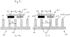
- Figure 3A shows a schematic side view of sections of the linear motor system 10 with the stator 11 and the rotor 21. On the left side, the arrangement of the stator elements 13 in normal operation or outside the braking zone 28 and the holding zone 26 is shown.
- the distance ⁇ n between the stator elements 13 or teeth of the linear motor system 10, ie the distance between their central axes perpendicular to the direction of movement of the rotor 21, is different from the distance ⁇ p between the corresponding central axes of the permanent magnets 23 of the rotor 21.
- 2 ⁇ p ⁇ 3 ⁇ n applies, as already mentioned above in connection with Fig. 1 was explained.
- the rotor 21 is moved relative to the stator elements 13 when the stator elements 13 are activated.
- the movement or the drive of the rotor 21 results from an interaction of the magnetic flux generated with the magnetic coils of the stator elements 13 with the magnetic element or the permanent magnets 23 of the rotor 21.
- the linear motor system 10 shown is a linear motor system with a longitudinal magnetic flux of the stator elements 13, which extends essentially in the direction of movement of the rotor 21.
- a holding zone can be implemented in the manner shown in the embodiment on the right side of FIG Figure 3A is shown.
- two selected stator elements 25 or teeth are shifted in comparison to the other stator elements 13 or 27 such that the distance between the selected stator elements 25 corresponds to the distance between the central axes of the permanent magnets 23 of the rotor 21.
- the selected stator elements 25 have ⁇ p ⁇ ⁇ n . If the rotor 21 has previously been braked sufficiently by the stator elements 27 in the braking zone 28 or is at a standstill, the selected stator elements 25 exert a magnetic attraction or holding force due to their increased distance, which corresponds to the distance between the permanent magnets 23 of the rotor 21 the runner 21 out.
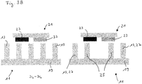
- the further embodiment of the linear motor system 10 from Figure 3C shows, on the other hand, selected stator elements 25, of which a stator element 35 or tooth can be moved such that it can be at least partially removed from the row of further stator elements 13, 25, 27.
- the removable stator element 35 can thus be switched between two states, wherein in the first state it is arranged between the further stator elements 13, 25, 27 and is therefore operated in an identical manner to how it is operated.
- the first state thus corresponds to normal operation of the linear motor system 10, in which the holding zone 26 is deactivated.
- the removable stator element 35 is no longer between the further stator elements 13, 25, 27, so that the second state of in Figure 3B shown embodiment corresponds to a missing tooth.
- the further selected stator elements 25, which are arranged on both sides of the removable stator element 35 exert a holding force on the rotor 21 in the same way as that for the embodiment of FIG Figure 3B is described.
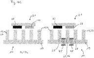
- FIGS. 4A , 4B and 4C show embodiments of the linear motor system 10 according to the invention, in which this is a linear motor system with a transverse magnetic flux of the stator elements 13, which extends essentially at right angles to the direction of movement of the rotor 21.
- one of the selected stator elements 25 is magnetically isolated from the adjacent stator elements and is therefore referred to as a magnetically isolable stator element 37.
- the magnetic insulation of the element 37 causes a gap between the stator elements 13, 25, 27, which interact with the magnetic element or the permanent magnet 23 of the rotor 21. Because of this gap, the adjacent stator elements 25 of the insulated stator element exert a holding force on the rotor 21 in a similar manner to that in the embodiment of FIG Figure 3B for a linear motor system 10 with longitudinal magnetic flux with a stator element removed.
- the lamination 19 of the stator 11 is interrupted by two non-magnetic connections 39 in order to magnetically close the stator element 37 with respect to the adjacent stator elements 25 isolate. Due to the holding force exerted on the rotor 21 by the adjacent stator elements 25, the stator elements 25, 37 form a holding zone 26 along the stator 11. This holding zone 26 can, however, be deactivated by means of a bridging device 41, which is shown on the left in FIG Figure 4A is shown. The non-magnetic connections 39 can be bridged by means of the bridging device 41, so that the stator element 37 no longer differs from the adjacent stator elements 13, 25.
- the selected stator element 25, 37 is by means of the bridging device 41 between a first state in which the magnetic insulation with respect to the adjacent stator elements 25 is removed and which in Figure 4A is shown on the left side, and switched to a second state, in which the stator element 37 is magnetically isolated from the adjacent stator elements 25, so that they exert a holding force on the rotor 21.
- FIG. 4B Another embodiment shown are the non-magnetic connections 39 of FIG Figure 4A replaced by permanent magnets 43.
- the permanent magnets 43 thus, like the non-magnetic connections 39, ensure magnetic insulation of the stator element 37 from the adjacent stator elements 25.
- the adjacent selected stator elements 25 thus in turn exert a holding force on the rotor 21 and thus define a holding zone 26 along the stator 11.
- This holding zone can be used just like in the Figure 4A illustrated embodiment can be canceled by means of a bridging device 41, as this on the left side of Figure 4B is shown.
- the non-magnetic connections 39 of Figure 4A and the permanent magnets 43 from Figure 4B replaced by electromagnets 45, which are each arranged on both sides of the stator element 37.
- the stator element 37 By activating the electromagnet 45, the stator element 37 in turn magnetically isolated from the adjacent selected stator elements 25, so that they exert a holding force on the rotor 21.
- the electromagnets 45 are deactivated, the stator element 37 does not differ from the further stator elements 13, 25, 27, as is shown on the left-hand side of FIG Figure 4C is shown.
- a bridging device 41 between the stator elements 25 is therefore not required. Instead, the selected stator elements 25, 37 are switched between activating and deactivating the electromagnets 45 between the first state without holding force and the second state with holding force for the rotor 21.
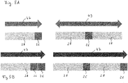
- additional security functions are implemented by setting up an additional, redundant holding zone 26 (cf. the left side of FIG Figure 5B ) or that a double sequence of braking zone 28 and stopping zone 26 is provided, that is to say a further braking zone 28 which follows a stopping zone 26 and a further stopping zone 26 which adjoins the further braking zone 28 (cf. the right-hand side of Figure 5B ).
- a braking zone 28 is provided between two holding zones 26, and a respective further braking zone 28 is located outside of these holding zones 26.
- the rotor 21 can be enclosed between the two holding zones 26.
- the redundant holding and braking zones 26, 28 shown can be achieved by the elements for controlling the stator elements 13, such as the devices 33 (cf. Fig. 2 ) for short-circuiting the magnetic coils are devices which are switched on in a passive state, ie are conductive. This means that these devices are non-conductive when activated and are therefore also activated when currents and / or voltages are switched off, for example in the event of a power failure.
- the curve 54 represents the length of a braking zone required to brake a rotor with a mass of 3 kg for speeds greater than 1 m / s, which are plotted on the x-axis.
- the required length in meters is plotted on the y-axis.
- the simulation calculations show that a relatively short braking zone with a length of less than 0.35 m is required for the indicated speeds of up to 4 m / s and the braking force for braking and holding the exemplary rotor 21 with a selected stator element 25 Mass of 3 kg is sufficient.
Landscapes
- Engineering & Computer Science (AREA)
- Power Engineering (AREA)
- Physics & Mathematics (AREA)
- Chemical & Material Sciences (AREA)
- Combustion & Propulsion (AREA)
- Electromagnetism (AREA)
- Microelectronics & Electronic Packaging (AREA)
- Linear Motors (AREA)
Priority Applications (2)
| Application Number | Priority Date | Filing Date | Title |
|---|---|---|---|
| EP18189508.7A EP3621188B1 (fr) | 2018-08-17 | 2018-08-17 | Système de moteur linéaire |
| US16/536,980 US11527982B2 (en) | 2018-08-17 | 2019-08-09 | Linear motor system |
Applications Claiming Priority (1)
| Application Number | Priority Date | Filing Date | Title |
|---|---|---|---|
| EP18189508.7A EP3621188B1 (fr) | 2018-08-17 | 2018-08-17 | Système de moteur linéaire |
Publications (2)
| Publication Number | Publication Date |
|---|---|
| EP3621188A1 true EP3621188A1 (fr) | 2020-03-11 |
| EP3621188B1 EP3621188B1 (fr) | 2022-10-05 |
Family
ID=63294156
Family Applications (1)
| Application Number | Title | Priority Date | Filing Date |
|---|---|---|---|
| EP18189508.7A Active EP3621188B1 (fr) | 2018-08-17 | 2018-08-17 | Système de moteur linéaire |
Country Status (2)
| Country | Link |
|---|---|
| US (1) | US11527982B2 (fr) |
| EP (1) | EP3621188B1 (fr) |
Families Citing this family (1)
| Publication number | Priority date | Publication date | Assignee | Title |
|---|---|---|---|---|
| US11912516B1 (en) * | 2022-08-30 | 2024-02-27 | Amazon Technologies, Inc. | Passive braking systems for container shuttles |
Citations (4)
| Publication number | Priority date | Publication date | Assignee | Title |
|---|---|---|---|---|
| US3771033A (en) * | 1970-07-07 | 1973-11-06 | Japan National Railway | Apparatus for propelling a movable body in a suspended state at a very high speed |
| EP0052346A2 (fr) * | 1980-11-11 | 1982-05-26 | Magnetbahn GmbH | Entraînement électrique ou générateur |
| EP2156979A1 (fr) * | 2008-08-19 | 2010-02-24 | Maurer Söhne GmbH & Co. KG | Entraînement linéaire, commerce de transport et procédé de fonctionnement d'un entraînement linéaire |
| WO2016202798A1 (fr) * | 2015-06-16 | 2016-12-22 | Indrivetec Ag | Système d'entraînement à moteur linéaire |
Family Cites Families (5)
| Publication number | Priority date | Publication date | Assignee | Title |
|---|---|---|---|---|
| JP3711111B2 (ja) * | 2003-01-23 | 2005-10-26 | 三菱電機株式会社 | リニアモータ |
| JP4145181B2 (ja) * | 2003-03-28 | 2008-09-03 | オリンパス株式会社 | 静電アクチュエータおよび変位方法 |
| US7385678B2 (en) * | 2004-10-05 | 2008-06-10 | Asml Netherlands B.V. | Positioning device and lithographic apparatus |
| JP5511713B2 (ja) * | 2011-02-28 | 2014-06-04 | 三菱電機株式会社 | リニアモータ |
| EP3487049B1 (fr) | 2017-11-17 | 2024-01-17 | Schneider Electric Industries SAS | Moteur linéaire á flux transversal |
-
2018
- 2018-08-17 EP EP18189508.7A patent/EP3621188B1/fr active Active
-
2019
- 2019-08-09 US US16/536,980 patent/US11527982B2/en active Active
Patent Citations (4)
| Publication number | Priority date | Publication date | Assignee | Title |
|---|---|---|---|---|
| US3771033A (en) * | 1970-07-07 | 1973-11-06 | Japan National Railway | Apparatus for propelling a movable body in a suspended state at a very high speed |
| EP0052346A2 (fr) * | 1980-11-11 | 1982-05-26 | Magnetbahn GmbH | Entraînement électrique ou générateur |
| EP2156979A1 (fr) * | 2008-08-19 | 2010-02-24 | Maurer Söhne GmbH & Co. KG | Entraînement linéaire, commerce de transport et procédé de fonctionnement d'un entraînement linéaire |
| WO2016202798A1 (fr) * | 2015-06-16 | 2016-12-22 | Indrivetec Ag | Système d'entraînement à moteur linéaire |
Also Published As
| Publication number | Publication date |
|---|---|
| EP3621188B1 (fr) | 2022-10-05 |
| US11527982B2 (en) | 2022-12-13 |
| US20200059187A1 (en) | 2020-02-20 |
Similar Documents
| Publication | Publication Date | Title |
|---|---|---|
| EP3625080B1 (fr) | Aiguille magnétique destinée à un système de transport | |
| EP1188222A1 (fr) | Organe d'entrainement lineaire magnetique | |
| EP1864370A1 (fr) | Moteur lineaire et procede pour faire fonctionner un moteur lineaire | |
| DE102006009311B4 (de) | Bremsvorrichtung für Linearmotor und Verfahren zur Positionierung eines beweglichen Abschnitts des Linearmotors | |
| WO2007003601A1 (fr) | Moteur lineaire synchrone | |
| EP3625079B1 (fr) | Aiguillage magnétique pour un système de transport | |
| EP3196902B1 (fr) | Circuit de reduction d'une part du flux continu dans le noyau magnetique doux d'un transformateur | |
| EP3621188B1 (fr) | Système de moteur linéaire | |
| EP3831639A1 (fr) | Fonction de sécurité pour un système de transport | |
| DE102006058725A1 (de) | Schaltungsanordnung zur gemeinsamen Pulsweitenmodulation von Ventilen mit Löschung | |
| DE102005039263B4 (de) | Steuervorrichtung und Verfahren zum Ansteuern eines Aktuators für eine Getriebeschaltstelle | |
| DE19522582A1 (de) | Schaltungsanordnung zum Betrieb eines Elektromagneten | |
| EP1404011A1 (fr) | Entraînement linéaire | |
| DE102011011857A1 (de) | Haltebremse | |
| EP1402546B1 (fr) | Entrainement lineaire electrodynamique | |
| EP0019890B1 (fr) | Circuit d'excitation d'électro-aimants dans des appareils d'enregistrement utilisés dans la technique du téléscripteur | |
| DE2504407C2 (de) | Zerhacker-Regler | |
| EP0340686A1 (fr) | Appareil d'attaque pour un électromoteur | |
| EP0243620B1 (fr) | Dispositif de commande pour le blocage d'un différentiel avec un élément de manoeuvre | |
| DE3524713A1 (de) | Bewegungsanordnung | |
| DE2138611A1 (de) | Bewegungssteuereinrichtung | |
| DE102018216223B3 (de) | Aktor und Verfahren zur Betätigung eines Hochspannungsschalters | |
| EP3347988B1 (fr) | Dispositif de commutation et procédé de commutation de consommateurs | |
| DE102020127822A1 (de) | Lineares Transportsystem und bewegliche Einheit eines linearen Transportsystems | |
| DE2329374A1 (de) | Steuerschaltung zur schnellerregung elektromagnetischer systeme, insbesondere eines schrittmotors |
Legal Events
| Date | Code | Title | Description |
|---|---|---|---|
| STAA | Information on the status of an ep patent application or granted ep patent |
Free format text: STATUS: EXAMINATION IS IN PROGRESS |
|
| PUAI | Public reference made under article 153(3) epc to a published international application that has entered the european phase |
Free format text: ORIGINAL CODE: 0009012 |
|
| 17P | Request for examination filed |
Effective date: 20190415 |
|
| AK | Designated contracting states |
Kind code of ref document: A1 Designated state(s): AL AT BE BG CH CY CZ DE DK EE ES FI FR GB GR HR HU IE IS IT LI LT LU LV MC MK MT NL NO PL PT RO RS SE SI SK SM TR |
|
| AX | Request for extension of the european patent |
Extension state: BA ME |
|
| STAA | Information on the status of an ep patent application or granted ep patent |
Free format text: STATUS: EXAMINATION IS IN PROGRESS |
|
| STAA | Information on the status of an ep patent application or granted ep patent |
Free format text: STATUS: EXAMINATION IS IN PROGRESS |
|
| GRAP | Despatch of communication of intention to grant a patent |
Free format text: ORIGINAL CODE: EPIDOSNIGR1 |
|
| STAA | Information on the status of an ep patent application or granted ep patent |
Free format text: STATUS: GRANT OF PATENT IS INTENDED |
|
| INTG | Intention to grant announced |
Effective date: 20220323 |
|
| GRAS | Grant fee paid |
Free format text: ORIGINAL CODE: EPIDOSNIGR3 |
|
| GRAA | (expected) grant |
Free format text: ORIGINAL CODE: 0009210 |
|
| STAA | Information on the status of an ep patent application or granted ep patent |
Free format text: STATUS: THE PATENT HAS BEEN GRANTED |
|
| AK | Designated contracting states |
Kind code of ref document: B1 Designated state(s): AL AT BE BG CH CY CZ DE DK EE ES FI FR GB GR HR HU IE IS IT LI LT LU LV MC MK MT NL NO PL PT RO RS SE SI SK SM TR |
|
| REG | Reference to a national code |
Ref country code: GB Ref legal event code: FG4D Free format text: NOT ENGLISH |
|
| REG | Reference to a national code |
Ref country code: CH Ref legal event code: EP |
|
| REG | Reference to a national code |
Ref country code: AT Ref legal event code: REF Ref document number: 1523380 Country of ref document: AT Kind code of ref document: T Effective date: 20221015 |
|
| REG | Reference to a national code |
Ref country code: IE Ref legal event code: FG4D Free format text: LANGUAGE OF EP DOCUMENT: GERMAN |
|
| REG | Reference to a national code |
Ref country code: DE Ref legal event code: R096 Ref document number: 502018010759 Country of ref document: DE |
|
| REG | Reference to a national code |
Ref country code: LT Ref legal event code: MG9D |
|
| REG | Reference to a national code |
Ref country code: NL Ref legal event code: MP Effective date: 20221005 |
|
| PG25 | Lapsed in a contracting state [announced via postgrant information from national office to epo] |
Ref country code: NL Free format text: LAPSE BECAUSE OF FAILURE TO SUBMIT A TRANSLATION OF THE DESCRIPTION OR TO PAY THE FEE WITHIN THE PRESCRIBED TIME-LIMIT Effective date: 20221005 |
|
| PG25 | Lapsed in a contracting state [announced via postgrant information from national office to epo] |
Ref country code: SE Free format text: LAPSE BECAUSE OF FAILURE TO SUBMIT A TRANSLATION OF THE DESCRIPTION OR TO PAY THE FEE WITHIN THE PRESCRIBED TIME-LIMIT Effective date: 20221005 Ref country code: PT Free format text: LAPSE BECAUSE OF FAILURE TO SUBMIT A TRANSLATION OF THE DESCRIPTION OR TO PAY THE FEE WITHIN THE PRESCRIBED TIME-LIMIT Effective date: 20230206 Ref country code: NO Free format text: LAPSE BECAUSE OF FAILURE TO SUBMIT A TRANSLATION OF THE DESCRIPTION OR TO PAY THE FEE WITHIN THE PRESCRIBED TIME-LIMIT Effective date: 20230105 Ref country code: LT Free format text: LAPSE BECAUSE OF FAILURE TO SUBMIT A TRANSLATION OF THE DESCRIPTION OR TO PAY THE FEE WITHIN THE PRESCRIBED TIME-LIMIT Effective date: 20221005 Ref country code: FI Free format text: LAPSE BECAUSE OF FAILURE TO SUBMIT A TRANSLATION OF THE DESCRIPTION OR TO PAY THE FEE WITHIN THE PRESCRIBED TIME-LIMIT Effective date: 20221005 Ref country code: ES Free format text: LAPSE BECAUSE OF FAILURE TO SUBMIT A TRANSLATION OF THE DESCRIPTION OR TO PAY THE FEE WITHIN THE PRESCRIBED TIME-LIMIT Effective date: 20221005 |
|
| PG25 | Lapsed in a contracting state [announced via postgrant information from national office to epo] |
Ref country code: RS Free format text: LAPSE BECAUSE OF FAILURE TO SUBMIT A TRANSLATION OF THE DESCRIPTION OR TO PAY THE FEE WITHIN THE PRESCRIBED TIME-LIMIT Effective date: 20221005 Ref country code: PL Free format text: LAPSE BECAUSE OF FAILURE TO SUBMIT A TRANSLATION OF THE DESCRIPTION OR TO PAY THE FEE WITHIN THE PRESCRIBED TIME-LIMIT Effective date: 20221005 Ref country code: LV Free format text: LAPSE BECAUSE OF FAILURE TO SUBMIT A TRANSLATION OF THE DESCRIPTION OR TO PAY THE FEE WITHIN THE PRESCRIBED TIME-LIMIT Effective date: 20221005 Ref country code: IS Free format text: LAPSE BECAUSE OF FAILURE TO SUBMIT A TRANSLATION OF THE DESCRIPTION OR TO PAY THE FEE WITHIN THE PRESCRIBED TIME-LIMIT Effective date: 20230205 Ref country code: HR Free format text: LAPSE BECAUSE OF FAILURE TO SUBMIT A TRANSLATION OF THE DESCRIPTION OR TO PAY THE FEE WITHIN THE PRESCRIBED TIME-LIMIT Effective date: 20221005 Ref country code: GR Free format text: LAPSE BECAUSE OF FAILURE TO SUBMIT A TRANSLATION OF THE DESCRIPTION OR TO PAY THE FEE WITHIN THE PRESCRIBED TIME-LIMIT Effective date: 20230106 |
|
| REG | Reference to a national code |
Ref country code: DE Ref legal event code: R097 Ref document number: 502018010759 Country of ref document: DE |
|
| PG25 | Lapsed in a contracting state [announced via postgrant information from national office to epo] |
Ref country code: SM Free format text: LAPSE BECAUSE OF FAILURE TO SUBMIT A TRANSLATION OF THE DESCRIPTION OR TO PAY THE FEE WITHIN THE PRESCRIBED TIME-LIMIT Effective date: 20221005 Ref country code: RO Free format text: LAPSE BECAUSE OF FAILURE TO SUBMIT A TRANSLATION OF THE DESCRIPTION OR TO PAY THE FEE WITHIN THE PRESCRIBED TIME-LIMIT Effective date: 20221005 Ref country code: EE Free format text: LAPSE BECAUSE OF FAILURE TO SUBMIT A TRANSLATION OF THE DESCRIPTION OR TO PAY THE FEE WITHIN THE PRESCRIBED TIME-LIMIT Effective date: 20221005 Ref country code: DK Free format text: LAPSE BECAUSE OF FAILURE TO SUBMIT A TRANSLATION OF THE DESCRIPTION OR TO PAY THE FEE WITHIN THE PRESCRIBED TIME-LIMIT Effective date: 20221005 Ref country code: CZ Free format text: LAPSE BECAUSE OF FAILURE TO SUBMIT A TRANSLATION OF THE DESCRIPTION OR TO PAY THE FEE WITHIN THE PRESCRIBED TIME-LIMIT Effective date: 20221005 |
|
| PLBE | No opposition filed within time limit |
Free format text: ORIGINAL CODE: 0009261 |
|
| STAA | Information on the status of an ep patent application or granted ep patent |
Free format text: STATUS: NO OPPOSITION FILED WITHIN TIME LIMIT |
|
| PG25 | Lapsed in a contracting state [announced via postgrant information from national office to epo] |
Ref country code: SK Free format text: LAPSE BECAUSE OF FAILURE TO SUBMIT A TRANSLATION OF THE DESCRIPTION OR TO PAY THE FEE WITHIN THE PRESCRIBED TIME-LIMIT Effective date: 20221005 Ref country code: AL Free format text: LAPSE BECAUSE OF FAILURE TO SUBMIT A TRANSLATION OF THE DESCRIPTION OR TO PAY THE FEE WITHIN THE PRESCRIBED TIME-LIMIT Effective date: 20221005 |
|
| 26N | No opposition filed |
Effective date: 20230706 |
|
| PG25 | Lapsed in a contracting state [announced via postgrant information from national office to epo] |
Ref country code: SI Free format text: LAPSE BECAUSE OF FAILURE TO SUBMIT A TRANSLATION OF THE DESCRIPTION OR TO PAY THE FEE WITHIN THE PRESCRIBED TIME-LIMIT Effective date: 20221005 |
|
| PGFP | Annual fee paid to national office [announced via postgrant information from national office to epo] |
Ref country code: FR Payment date: 20230828 Year of fee payment: 6 |
|
| PGFP | Annual fee paid to national office [announced via postgrant information from national office to epo] |
Ref country code: DE Payment date: 20231027 Year of fee payment: 6 |
|
| PG25 | Lapsed in a contracting state [announced via postgrant information from national office to epo] |
Ref country code: MC Free format text: LAPSE BECAUSE OF FAILURE TO SUBMIT A TRANSLATION OF THE DESCRIPTION OR TO PAY THE FEE WITHIN THE PRESCRIBED TIME-LIMIT Effective date: 20221005 |
|
| REG | Reference to a national code |
Ref country code: CH Ref legal event code: PL |
|
| PG25 | Lapsed in a contracting state [announced via postgrant information from national office to epo] |
Ref country code: MC Free format text: LAPSE BECAUSE OF FAILURE TO SUBMIT A TRANSLATION OF THE DESCRIPTION OR TO PAY THE FEE WITHIN THE PRESCRIBED TIME-LIMIT Effective date: 20221005 |
|
| PG25 | Lapsed in a contracting state [announced via postgrant information from national office to epo] |
Ref country code: LU Free format text: LAPSE BECAUSE OF NON-PAYMENT OF DUE FEES Effective date: 20230817 |
|
| GBPC | Gb: european patent ceased through non-payment of renewal fee |
Effective date: 20230817 |
|
| PG25 | Lapsed in a contracting state [announced via postgrant information from national office to epo] |
Ref country code: LU Free format text: LAPSE BECAUSE OF NON-PAYMENT OF DUE FEES Effective date: 20230817 Ref country code: CH Free format text: LAPSE BECAUSE OF NON-PAYMENT OF DUE FEES Effective date: 20230831 |
|
| REG | Reference to a national code |
Ref country code: BE Ref legal event code: MM Effective date: 20230831 |
|
| REG | Reference to a national code |
Ref country code: IE Ref legal event code: MM4A |