EP3620832A1 - Projection type image display device - Google Patents
Projection type image display device Download PDFInfo
- Publication number
- EP3620832A1 EP3620832A1 EP19194131.9A EP19194131A EP3620832A1 EP 3620832 A1 EP3620832 A1 EP 3620832A1 EP 19194131 A EP19194131 A EP 19194131A EP 3620832 A1 EP3620832 A1 EP 3620832A1
- Authority
- EP
- European Patent Office
- Prior art keywords
- polarized light
- lens
- light
- incident
- fly
- Prior art date
- Legal status (The legal status is an assumption and is not a legal conclusion. Google has not performed a legal analysis and makes no representation as to the accuracy of the status listed.)
- Granted
Links
Images



Classifications
-
- G—PHYSICS
- G03—PHOTOGRAPHY; CINEMATOGRAPHY; ANALOGOUS TECHNIQUES USING WAVES OTHER THAN OPTICAL WAVES; ELECTROGRAPHY; HOLOGRAPHY
- G03B—APPARATUS OR ARRANGEMENTS FOR TAKING PHOTOGRAPHS OR FOR PROJECTING OR VIEWING THEM; APPARATUS OR ARRANGEMENTS EMPLOYING ANALOGOUS TECHNIQUES USING WAVES OTHER THAN OPTICAL WAVES; ACCESSORIES THEREFOR
- G03B21/00—Projectors or projection-type viewers; Accessories therefor
- G03B21/14—Details
- G03B21/142—Adjusting of projection optics
-
- G—PHYSICS
- G02—OPTICS
- G02B—OPTICAL ELEMENTS, SYSTEMS OR APPARATUS
- G02B3/00—Simple or compound lenses
- G02B3/0006—Arrays
- G02B3/0037—Arrays characterized by the distribution or form of lenses
- G02B3/0043—Inhomogeneous or irregular arrays, e.g. varying shape, size, height
-
- G—PHYSICS
- G03—PHOTOGRAPHY; CINEMATOGRAPHY; ANALOGOUS TECHNIQUES USING WAVES OTHER THAN OPTICAL WAVES; ELECTROGRAPHY; HOLOGRAPHY
- G03B—APPARATUS OR ARRANGEMENTS FOR TAKING PHOTOGRAPHS OR FOR PROJECTING OR VIEWING THEM; APPARATUS OR ARRANGEMENTS EMPLOYING ANALOGOUS TECHNIQUES USING WAVES OTHER THAN OPTICAL WAVES; ACCESSORIES THEREFOR
- G03B21/00—Projectors or projection-type viewers; Accessories therefor
- G03B21/14—Details
- G03B21/20—Lamp housings
- G03B21/2073—Polarisers in the lamp house
-
- G—PHYSICS
- G02—OPTICS
- G02B—OPTICAL ELEMENTS, SYSTEMS OR APPARATUS
- G02B27/00—Optical systems or apparatus not provided for by any of the groups G02B1/00 - G02B26/00, G02B30/00
- G02B27/09—Beam shaping, e.g. changing the cross-sectional area, not otherwise provided for
- G02B27/0905—Dividing and/or superposing multiple light beams
-
- G—PHYSICS
- G02—OPTICS
- G02B—OPTICAL ELEMENTS, SYSTEMS OR APPARATUS
- G02B27/00—Optical systems or apparatus not provided for by any of the groups G02B1/00 - G02B26/00, G02B30/00
- G02B27/09—Beam shaping, e.g. changing the cross-sectional area, not otherwise provided for
- G02B27/0938—Using specific optical elements
- G02B27/095—Refractive optical elements
- G02B27/0955—Lenses
- G02B27/0961—Lens arrays
-
- G—PHYSICS
- G02—OPTICS
- G02B—OPTICAL ELEMENTS, SYSTEMS OR APPARATUS
- G02B27/00—Optical systems or apparatus not provided for by any of the groups G02B1/00 - G02B26/00, G02B30/00
- G02B27/28—Optical systems or apparatus not provided for by any of the groups G02B1/00 - G02B26/00, G02B30/00 for polarising
- G02B27/283—Optical systems or apparatus not provided for by any of the groups G02B1/00 - G02B26/00, G02B30/00 for polarising used for beam splitting or combining
- G02B27/285—Optical systems or apparatus not provided for by any of the groups G02B1/00 - G02B26/00, G02B30/00 for polarising used for beam splitting or combining comprising arrays of elements, e.g. microprisms
-
- G—PHYSICS
- G02—OPTICS
- G02B—OPTICAL ELEMENTS, SYSTEMS OR APPARATUS
- G02B3/00—Simple or compound lenses
- G02B3/0006—Arrays
- G02B3/0037—Arrays characterized by the distribution or form of lenses
- G02B3/0056—Arrays characterized by the distribution or form of lenses arranged along two different directions in a plane, e.g. honeycomb arrangement of lenses
-
- G—PHYSICS
- G02—OPTICS
- G02B—OPTICAL ELEMENTS, SYSTEMS OR APPARATUS
- G02B3/00—Simple or compound lenses
- G02B3/0006—Arrays
- G02B3/0037—Arrays characterized by the distribution or form of lenses
- G02B3/0062—Stacked lens arrays, i.e. refractive surfaces arranged in at least two planes, without structurally separate optical elements in-between
-
- G—PHYSICS
- G03—PHOTOGRAPHY; CINEMATOGRAPHY; ANALOGOUS TECHNIQUES USING WAVES OTHER THAN OPTICAL WAVES; ELECTROGRAPHY; HOLOGRAPHY
- G03B—APPARATUS OR ARRANGEMENTS FOR TAKING PHOTOGRAPHS OR FOR PROJECTING OR VIEWING THEM; APPARATUS OR ARRANGEMENTS EMPLOYING ANALOGOUS TECHNIQUES USING WAVES OTHER THAN OPTICAL WAVES; ACCESSORIES THEREFOR
- G03B21/00—Projectors or projection-type viewers; Accessories therefor
- G03B21/14—Details
- G03B21/20—Lamp housings
- G03B21/2066—Reflectors in illumination beam
-
- G—PHYSICS
- G03—PHOTOGRAPHY; CINEMATOGRAPHY; ANALOGOUS TECHNIQUES USING WAVES OTHER THAN OPTICAL WAVES; ELECTROGRAPHY; HOLOGRAPHY
- G03B—APPARATUS OR ARRANGEMENTS FOR TAKING PHOTOGRAPHS OR FOR PROJECTING OR VIEWING THEM; APPARATUS OR ARRANGEMENTS EMPLOYING ANALOGOUS TECHNIQUES USING WAVES OTHER THAN OPTICAL WAVES; ACCESSORIES THEREFOR
- G03B21/00—Projectors or projection-type viewers; Accessories therefor
- G03B21/14—Details
- G03B21/20—Lamp housings
- G03B21/208—Homogenising, shaping of the illumination light
-
- H—ELECTRICITY
- H04—ELECTRIC COMMUNICATION TECHNIQUE
- H04N—PICTORIAL COMMUNICATION, e.g. TELEVISION
- H04N13/00—Stereoscopic video systems; Multi-view video systems; Details thereof
- H04N13/30—Image reproducers
- H04N13/302—Image reproducers for viewing without the aid of special glasses, i.e. using autostereoscopic displays
- H04N13/307—Image reproducers for viewing without the aid of special glasses, i.e. using autostereoscopic displays using fly-eye lenses, e.g. arrangements of circular lenses
-
- H—ELECTRICITY
- H04—ELECTRIC COMMUNICATION TECHNIQUE
- H04N—PICTORIAL COMMUNICATION, e.g. TELEVISION
- H04N9/00—Details of colour television systems
- H04N9/12—Picture reproducers
- H04N9/31—Projection devices for colour picture display, e.g. using electronic spatial light modulators [ESLM]
-
- H—ELECTRICITY
- H04—ELECTRIC COMMUNICATION TECHNIQUE
- H04N—PICTORIAL COMMUNICATION, e.g. TELEVISION
- H04N9/00—Details of colour television systems
- H04N9/12—Picture reproducers
- H04N9/31—Projection devices for colour picture display, e.g. using electronic spatial light modulators [ESLM]
- H04N9/3102—Projection devices for colour picture display, e.g. using electronic spatial light modulators [ESLM] using two-dimensional electronic spatial light modulators
- H04N9/3105—Projection devices for colour picture display, e.g. using electronic spatial light modulators [ESLM] using two-dimensional electronic spatial light modulators for displaying all colours simultaneously, e.g. by using two or more electronic spatial light modulators
-
- H—ELECTRICITY
- H04—ELECTRIC COMMUNICATION TECHNIQUE
- H04N—PICTORIAL COMMUNICATION, e.g. TELEVISION
- H04N9/00—Details of colour television systems
- H04N9/12—Picture reproducers
- H04N9/31—Projection devices for colour picture display, e.g. using electronic spatial light modulators [ESLM]
- H04N9/3141—Constructional details thereof
- H04N9/315—Modulator illumination systems
- H04N9/3167—Modulator illumination systems for polarizing the light beam
Definitions
- the present disclosure relates to a projection type image display device including a pair of fly-eye lenses.
- a projection type image display device may include a pair of fly-eye lenses in an illumination optical system.
- Each fly-eye lens includes a plurality of rectangular lens cells.
- each lens cell provided in the fly-eye lens is often eccentric.
- a degree of eccentricity of each lens cell of a fly-eye lens varies depending on the position of the lens cell provided in the fly-eye lens, such that there exists a step difference at the boundary between two lens cells adjacent to each other (refer to Japanese Unexamined Patent Application Publication No. 2002-23108 or Japanese Unexamined Patent Application Publication No. 2007-78731 ).
- a shape error which is different from the design shape called "sagging" or "chipping" occurs at the end portion of each lens cell. This kind of shape error adversely affects the quality of an image to be projected.
- the fly-eye lens so as to eliminate the step difference at the boundary between the lens cells.
- a size of an illumination range by each lens cell is changed, and thus the brightness of light emitted from each lens cell and superimposed on each other becomes uneven in a plane.
- An object of one or more embodiments is to provide a projection type image display device capable of avoiding an adverse effect on the image quality caused by a step difference existing at a boundary between the lens cells adjacent to each other while minimizing a change in a size of an illumination range by each lens cell of a fly-eye lens.
- An aspect of one more embodiments provides a projection type image display device, including: a first fly-eye lens configured to include a plurality of first lens cells arranged in a first direction and a second direction orthogonal to the first direction, and to divide an incident luminous flux into partial luminous fluxes for the respective first lens cells; a second fly-eye lens configured to include a plurality of second lens cells arranged in the first direction and the second direction, and to individually condense the respective partial luminous fluxes emitted from the respective first lens cells by the respective second lens cells; and a polarized light conversion element configured to emit a first polarized light used as illumination light, and to convert a second polarized light not used as the illumination light into the first polarized light to emit the converted first polarized light, out of the first polarized light and the second polarized light included in the light incident from the second fly-eye lens.
- a reflection surface including a predetermined angle with respect to an incident surface of the light incident from the second fly-eye lens and reflecting the incident light and a polarized light separation surface including the predetermined angle, reflecting the first polarized light included in the incident light, and transmitting the second polarized light are alternately formed in the first direction at an interval of 1/2 of a size of the second lens cell in the first direction.
- a region sandwiched between the reflection surface and the polarized light separation surface on a light emission surface of the polarized light conversion element is alternately formed with a polarized light conversion region to which a 1/2 wavelength plate is stuck and a non-polarized light conversion region to which the 1/2 wavelength plate is not stuck in the first direction.
- the 1/2 wavelength plate is opposite to the plurality of the second lens cells arranged in the second direction, the plurality of the second lens cells are respectively eccentric in the first and second directions.
- End portions of two second lens cells at a first boundary between the two second lens cells adjacent to each other in the first direction are deviated in the thickness direction of the second fly-eye lens, such that a step difference exists at the first boundary.
- End portions of two second lens cells at a second boundary between the two second lens cells adjacent to each other in the second direction coincide with each other in the thickness direction of the second fly-eye lens, such that a step difference does not exist at the second boundary.
- Central light transmitted through a central portion of the second lens cell in the first direction is incident on the polarized light separation surface, and the polarized light separation surface reflects the first polarized light included in the central light and transmits the second polarized light.
- the reflection surface on which the first polarized light reflected by the polarized light separation surface is incident reflects the first polarized light and causes the polarized light conversion element to emit the reflected first polarized light
- the 1/2 wavelength plate on which the second polarized light transmitted through the polarized light separation surface is incident converts the second polarized light into the first polarized light and causes the polarized light conversion element to emit the converted first polarized light
- Peripheral light transmitted through a peripheral portion near the first boundary between the second lens cells is incident on the reflection surface and the reflection surface reflects the peripheral light, and the polarized light separation surface on which the peripheral light reflected by the reflection surface is incident reflects the first polarized light included in the peripheral light and transmits the second polarized light.
- the 1/2 wavelength plate on which the first polarized light reflected by the polarized light separation surface is incident converts the first polarized light into the second polarized light and causes the polarized light conversion element to emit the converted second polarized light
- the other reflection surface on which the second polarized light transmitted through the polarized light separation surface is incident reflects the second polarized light and causes the polarized light conversion element to emit the reflected second polarized light.
- a projection type image display device according to one or more embodiments will be described with reference to the accompanying drawings.
- a light source 1 emits white light.
- the light source 1 is an ultra-high-pressure mercury lamp.
- the white light is an indefinite polarized light including P-polarized light and S-polarized light.
- a type of the light source 1 is not limited, and a light emitting diode (LED) or a laser diode may be used as the light source 1.
- the light source 1 may emit light of a color other than white.
- the white light is irradiated on a first fly-eye lens 2.
- the first fly-eye lens 2 has a structure in which a plurality of rectangular lens cells are arranged in a matrix shape in a first direction and in a second direction orthogonal to the first direction in a plane.
- the first and second directions respectively correspond to a horizontal direction (X direction) and a vertical direction (Y direction) of an image to be projected by the projection type image display device 100.
- the first fly-eye lens 2 divides the luminous flux of the irradiated white light into partial luminous fluxes for each lens cell.
- each partial luminous flux emitted from the first fly-eye lens 2 is irradiated on a second fly-eye lens 3.
- the second fly-eye lens 3 has a structure in which a plurality of rectangular lens cells are arranged in a matrix shape in the X direction and Y direction in a plane.
- Each lens cell of the second fly-eye lens 3 corresponds to each lens cell of the first fly-eye lens 2 by one to one.
- Each lens cell of the second fly-eye lens 3 individually condenses each partial luminous flux emitted from each lens cell of the first fly-eye lens 2.
- Each lens cell is eccentric such that the partial luminous fluxes emitted from the respective lens cells of the second fly-eye lens 3 are condensed and the respective partial luminous fluxes are superimposed on each other.
- a degree of eccentricity of each lens cell of the second fly-eye lens 3 varies depending on a position of the lens cell.
- the second fly-eye lens 3 is configured in such a manner that, in the X direction and the Y direction, a step difference exists at a boundary between the lens cells adjacent to each other in one direction and a step difference does not exist at a boundary between the lens cells adjacent to each other in the other direction.
- the number of lens cells of the first fly-eye lens 2 and the second fly-eye lens 3 is reduced to simplify the drawing.
- the number and shape of the lens cells of the first fly-eye lens 2 and the second fly-eye lens 3 will be described in detail later.
- the partial luminous flux emitted from each lens cell of the second fly-eye lens 3 is irradiated on a polarized light conversion element 4.
- the polarized light conversion element 4 converts the second polarized light that is the other of the P-polarized light and S-polarized light and is not used as illumination light into the first polarized light.
- the first polarized light is the S-polarized light and the second polarized light is the P-polarized light.
- the polarized light conversion element 4 mainly emits the S-polarized light by converting the P-polarized light into the S-polarized light, but may emit the P-polarized light by converting the S-polarized light into the P-polarized light.
- the S-polarized light as polarized light at the time of being irradiated on the second fly-eye lens 3 is used as the illumination light, but the P-polarized light may be configured to be used as the illumination light.
- the light mainly formed of the S-polarized light emitted from the polarized light conversion element 4 is incident on a cross dichroic mirror 6, in a state where the light is condensed by a condensing action performed by the second fly-eye lens 3 and the respective partial luminous fluxes are superimposed on each other. If each lens cell of the second fly-eye lens 3 is not eccentric and each lens cell does not perform the condensing action, a condenser lens 5 as indicated by a two-dash chain line is required in a rear stage of the polarized light conversion element 4.
- the condenser lens 5 can be configured to be omitted by causing each lens cell of the second fly-eye lens 3 to be eccentric.
- the cross dichroic mirror 6 separates the incident light into red light (hereinafter referred to as R light), green light (hereinafter referred to as G light), and blue light (hereinafter referred to as B light).
- R light red light
- G light green light
- B light blue light
- the R light and the G light are reflected by a reflection mirror 7 such that a traveling direction of the R light and the G light is bent by 90 degrees, after which the R light and the G light is directed to a dichroic mirror 9.
- the B light is reflected by a reflection mirror 8 such that a traveling direction of the B light is bent by 90 degrees, after which the B light is directed to a field lens 16.
- the R light out of the R light and the G light is transmitted through the dichroic mirror 9 and is directed to a field lens 10.
- the G light is reflected by the dichroic mirror 9 such that the traveling direction of the G light is bent by 90 degrees, after which the G light is directed to a field lens 13.
- the field lenses 10, 13, and 16 are lenses for aligning the traveling direction of light at the peripheral portion of the field of view.
- the R light transmitted through the field lens 10 is transmitted through a polarizing plate 11 and is incident on a red image display element 12.
- the polarizing plate 11, and polarizing plates 14 and 17 which will be described later are wire grid polarizing plates.
- the red image display element 12, and a green image display element 15 and a blue image display element 18 which will be described later are reflection type liquid crystal display elements.
- the reflection type liquid crystal display element is a spatial light modulation element referred to as LCOS (Liquid Crystal On Silicon).
- the red image display element 12 modulates and reflects the R light according to a red component of an image to be projected.
- the red image display element 12 modulates the R light, thereby converting the S-polarized light into the P-polarized light. Accordingly, the modulated light of the R light reflected by the red image display element 12 is reflected by the polarizing plate 11 such that the traveling direction of the modulated light of the R light is bent by 90 degrees, after which the modulated light thereof is directed to a polarizing plate 19 stuck to a color combining prism 22.
- the G light is transmitted through the field lens 13 and the polarizing plate 14, and then is incident on the green image display element 15.
- the green image display element 15 modulates and reflects the G light according to a green component of the image to be projected.
- the green image display element 15 modulates the G light, thereby converting the S-polarized light into the P-polarized light. Accordingly, the modulated light of the G light reflected by the green image display element 15 is reflected by the polarizing plate 14 such that the traveling direction of the modulated light of the G light is bent by 90 degrees, after which the modulated light thereof is directed to a polarizing plate 20 stuck to the color combining prism 22.
- the B light is transmitted through the field lens 16 and the polarizing plate 17, and then is incident on the blue image display element 18.
- the blue image display element 18 modulates and reflects the B light according to a blue component of the image to be projected.
- the blue image display element 18 modulates the B light, thereby converting the S-polarized light into the P-polarized light. Accordingly, the modulated light of the B light reflected by the blue image display element 18 is reflected by the polarizing plate 17 such that the traveling direction of the modulated light of the B light is bent by 90 degrees, after which the modulated light thereof is directed to a polarizing plate 21 stuck to the color combining prism 22.
- the polarizing plates 19, 20, and 21 are wire grid polarizing plates.
- the polarizing plates 19, 20, and 21 remove the unnecessary S-polarized light included in the respective incident R light, G light, and B light. Therefore, only the necessary P-polarized light is incident on the color combining prism 22.
- the color combining prism 22 performs the color combination of the R light, the G light, and the B light, and then emits the combined light toward a projection lens 23.
- the projection lens 23 enlarges and projects the combined light on an unillustrated screen. As described above, the projection type image display device 100 displays the image on the screen.
- FIG. 2 illustrates a state in which the first fly-eye lens 2, the second fly-eye lens 3, and the polarized light conversion element 4 are viewed from the side.
- light emitted from each lens cell of the second fly-eye lens 3 and superimposed on each other is configured to be rotated by 90 degrees and to be projected on the screen. Accordingly, a height direction of when the first fly-eye lens 2, the second fly-eye lens 3, and the polarized light conversion element 4 are viewed from the side is the X direction.
- 8 pieces of lens cells 201 are arranged in the X direction in the first fly-eye lens 2.
- the lens cell 201 is a convex lens and is not eccentric.
- the 8 pieces of lens cells 201 have the same height.
- 8 pieces of lens cells 301 are arranged in the X direction so as to correspond to the respective lens cells 201.
- the lens cell 301 is a convex lens and is eccentric in the X direction.
- the lens cell 301 positioned above the center in the X direction indicated by a one-dash chain line is eccentric downward, and the lens cell 301 positioned below the center is eccentric upward. That is, the lens cell 301 positioned thereabove and the lens cell 301 positioned therebelow are mutually eccentric to the center side in the X direction. A degree of eccentricity of the lens cell 301 becomes large as the lens cell 301 goes from the center toward an upper end portion or a lower end portion. 8 pieces of lens cells 301 have the same height.
- each lens cell 301 of the plurality of lens cells 301 arranged in the X direction is defined as 301a and the upper end portion thereof is defined as 301b.
- the end portion 301a and the end portion 301b of two lens cells 301 adjacent to each other in the X direction do not coincide with each other and are deviated in the thickness direction of the second fly-eye lens 3. That is, a step difference exists at a boundary between two lens cells 301 adjacent to each other. Note that there is no step difference at a boundary between two lens cells 301 sandwiching the center in the X direction indicated by the one-dash chain line.
- FIG. 3 illustrates a state in which the first fly-eye lens 2, the second fly-eye lens 3, and the polarized light conversion element 4 are viewed from the top.
- a width direction of when the first fly-eye lens 2, the second fly-eye lens 3, and the polarized light conversion element 4 are viewed from the top is the Y direction.
- 14 pieces of lens cells 201 are arranged in the Y direction of the first fly-eye lens 2.
- 14 pieces of lens cells 301 are arranged in the Y direction so as to correspond to the respective lens cells 201.
- the lens cell 301 is eccentric in the Y direction.
- the lens cell 301 positioned on one side (upper portion of FIG. 3 ) with respect to the center in the Y direction indicated by a one-dash chain line is eccentric to the other side (lower portion of FIG. 3 ), and the lens cell 301 positioned on the other side (lower portion of FIG. 3 ) with respect to the center is eccentric to one side (upper portion of FIG. 3 ). That is, the lens cell 301 positioned on one side and the lens cell 301 positioned on the other side are mutually eccentric to the center side in the Y direction. A degree of eccentricity of the lens cell 301 becomes large as the lens cell 301 goes from the center to the end portion in the Y direction. Heights of the 14 pieces of lens cells 301 increase in order from the end portion in the Y direction to the center.
- the lower end portion of FIG. 3 of the surface of each lens cell 301 of the plurality of lens cells 301 arranged in the Y direction is defined as 301c and the upper end portion thereof is defined as 301d.
- the end portion 301c and the end portion 301d of two lens cells 301 adjacent to each other in the Y direction coincide with each other and are not deviated in the thickness direction of the second fly-eye lens 3. That is, in the Y direction, there is no step difference at a boundary between two lens cells 301 adjacent to each other.
- a reflection surface 41 indicated by a solid line and a polarized light separation surface 42 indicated by a broken line are alternately formed in the X direction on the inside of the polarized light conversion element 4.
- the reflection surface 41 and the polarized light separation surface 42 are formed so as to have a predetermined angle with respect to an incident surface of light of the polarized light conversion element 4.
- the predetermined angle is desirably 45 degrees.
- the reflection surface 41 reflects the incident light
- the polarized light separation surface 42 transmits the P-polarized light and reflects the S-polarized light.
- Regions sandwiched between the reflection surface 41 and the polarized light separation surface 42 are defined as regions 43 and 44.
- the distance between the region 43 and the region 44 in the X direction is the same.
- the size of each lens cell 301 in the X direction is the same as the distance in the X direction obtained by combining the regions 43 and 44.
- a 1/2 wavelength plate 45 is stuck to a portion of each region 44 on a light emission surface of the polarized light conversion element 4.
- the distance in the X direction of the 1/2 wavelength plate 45 is 1/2 of the size of the lens cell 301 in the X direction.
- the 1/2 wavelength plate 45 is stuck to the portion of each region 44 on the light emission surface of the polarized light conversion element 4, and the region 44 is referred to as the polarized light conversion region 44.
- the 1/2 wavelength plate 45 is not stuck to a portion of each region 43 on the light emission surface of the polarized light conversion element 4, and the region 43 is referred to as the non-polarized light conversion region 43.
- the non-polarized light conversion region 43 and the polarized light conversion region 44 are alternately formed in the X direction at an interval of 1/2 of the size of the lens cell 301 in the X direction in the polarized light conversion element 4.
- FIG. 4 illustrates a state in which the second fly-eye lens 3 and the polarized light conversion element 4 are viewed from the side of the second fly-eye lens 3.
- the positions of the non-polarized light conversion region 43 of the polarized light conversion element 4 and the polarized light conversion region 44 thereof in FIG. 4 indicate the positions on the light emission surface of the polarized light conversion element 4.
- the 1/2 wavelength plate 45 is opposite to the plurality of lens cells 301 arranged in the Y direction.
- the end portions 301a and 301b forming the boundary between two lens cells 301 adjacent to each other in the X direction have the step difference, and a state of the step difference is indicated by a thick solid line.
- the step difference of the boundary indicated by the thick solid line is opposite to the non-polarized light conversion region 43 to which the 1/2 wavelength plate 45 is not stuck.
- the end portions 301c and 301d forming the boundary between two lens cells 301 adjacent to each other in the Y direction do not have the step difference, and intersect the 1/2 wavelength plate 45.
- partial luminous flux including the P-polarized light and the S-polarized light emitted from each lens cell 201 of the first fly-eye lens 2 is incident on each lens cell 301 of the second fly-eye lens 3.
- central light L1 transmitted through a central portion of the lens cell 301 in the X direction and peripheral light L2 transmitted through a peripheral portion near the boundary are separately considered.
- the P-polarized light out of the P-polarized light and the S-polarized light included in the central light L1 is transmitted through the polarized light separation surface 42 and is incident on the 1/2 wavelength plate 45. Since the 1/2 wavelength plate 45 converts the P-polarized light into the S-polarized light, the S-polarized light is emitted from the polarized light conversion region 44.
- the S-polarized light out of the P-polarized light and the S-polarized light included in the central light L1 is reflected by the polarized light separation surface 42 such that the traveling direction of the S-polarized light is bent by 90 degrees, after which the S-polarized light is further reflected by the reflection surface 41 and the traveling direction thereof is bent by 90 degrees, such that the S-polarized light is emitted from the non-polarized light conversion region 43.
- the P-polarized light and the S-polarized light included in the peripheral light L2 are reflected by the reflection surface 41 such that the traveling directions of the P-polarized light and the S-polarized light are bent by 90 degrees, after which the P-polarized light and the S-polarized light are incident on the polarized light separation surface 42.
- the P-polarized light out of the P-polarized light and the S-polarized light which are incident on the polarized light separation surface 42 is transmitted through the polarized light separation surface 42 and then is incident on the other reflection surface 41.
- the other reflection surface 41 is the next reflection surface 41 on which the P-polarized light transmitted through the polarized light separation surface 42 is incident.
- the P-polarized light incident on the reflection surface 41 is reflected by the reflection surface 41 and the traveling direction thereof is bent by 90 degree, such that the P-polarized light is emitted from the non-polarized light conversion region 43.
- the S-polarized light out of the P-polarized light and the S-polarized light incident on the polarized light separation surface 42 is reflected by the polarized light separation surface 42 such that the traveling direction of the S-polarized light is bent by 90 degrees, after which the S-polarized light is incident on the 1/2 wavelength plate 45. Since the 1/2 wavelength plate 45 converts the S-polarized light into the P-polarized light, the P-polarized light is emitted from the polarized light conversion region 44.
- the step difference exists at the boundary (first boundary) between two lens cells 301 adjacent to each other in the X direction, whereas the step difference does not exist at the boundary (second boundary) between two lens cells 301 adjacent to each other in the Y direction. Since only the boundary between the lens cells 301 adjacent to each other in the Y direction does not have the step difference, a change in the size of the illumination range by each lens cell 301 can be minimized.
- the size of the illumination range by each lens cell 301 is almost the same as the size of the illumination range in a shape having the step differences at the boundaries in the X direction and the Y direction, and the brightness of the light emitted from the respective lens cells 301 and superimposed on each other is unlikely to become uneven in the plane.
- the polarized light conversion element 4 emits the P-polarized light based upon the peripheral light L2 transmitted through the peripheral portion near the boundary of the lens cell 301 in the X direction.
- the P-polarized light is not used as the illumination light, even though there is a shape error of "sagging" or “chipping" at the end portion of the lens cell 301, the quality of the image to be projected on the screen is not adversely affected.
- the peripheral light transmitted through the peripheral portion near the boundary of the lens cell 301 in the Y direction also does not adversely affect the quality of the image to be projected on the screen.
- the plurality of lens cells 301 are eccentric in both the X direction and Y direction such that the respective partial luminous fluxes emitted from the respective lens cells 301 are superimposed on each other. Therefore, the projection type image display device 100 does not require the condenser lens 5 for superimposing the respective partial luminous fluxes on the rear stage of the polarized light conversion element 4.
- the number of components can be reduced by a configuration in which the condenser lens 5 is omitted, and the brightness is not reduced by allowing the light to be transmitted through the condenser lens 5.
- the projection type image display device it is possible not only to minimize the change in the size of the illumination range by each lens cell of the fly-eye lens, but also to avoid the adverse effect on the image quality caused by the step difference existing at the boundary between the lens cells adjacent to each other.
- the present invention is not limited to one or more embodiments described above, and various modifications can be made within a range not departing from the scope of the present invention.
- the projection type image display device of the present disclosure may be configured to include a pair of fly-eye lenses and a polarized light conversion element, and the configuration of the rear stage of the polarized light conversion element is not particularly limited.
Landscapes
- Physics & Mathematics (AREA)
- General Physics & Mathematics (AREA)
- Engineering & Computer Science (AREA)
- Multimedia (AREA)
- Signal Processing (AREA)
- Optics & Photonics (AREA)
- Projection Apparatus (AREA)
- Liquid Crystal (AREA)
- Non-Portable Lighting Devices Or Systems Thereof (AREA)
- Transforming Electric Information Into Light Information (AREA)
Abstract
Description
- The present disclosure relates to a projection type image display device including a pair of fly-eye lenses.
- A projection type image display device may include a pair of fly-eye lenses in an illumination optical system. Each fly-eye lens includes a plurality of rectangular lens cells. In order to improve the performance of the illumination optical system, each lens cell provided in the fly-eye lens is often eccentric.
- A degree of eccentricity of each lens cell of a fly-eye lens varies depending on the position of the lens cell provided in the fly-eye lens, such that there exists a step difference at the boundary between two lens cells adjacent to each other (refer to Japanese Unexamined Patent Application Publication No.
2002-23108 2007-78731 - Therefore, it is conceivable to design and manufacture the fly-eye lens so as to eliminate the step difference at the boundary between the lens cells. However, when the shape of the fly-eye lens is corrected to eliminate the step difference at the boundary therebetween, a size of an illumination range by each lens cell is changed, and thus the brightness of light emitted from each lens cell and superimposed on each other becomes uneven in a plane.
- An object of one or more embodiments is to provide a projection type image display device capable of avoiding an adverse effect on the image quality caused by a step difference existing at a boundary between the lens cells adjacent to each other while minimizing a change in a size of an illumination range by each lens cell of a fly-eye lens.
- An aspect of one more embodiments provides a projection type image display device, including: a first fly-eye lens configured to include a plurality of first lens cells arranged in a first direction and a second direction orthogonal to the first direction, and to divide an incident luminous flux into partial luminous fluxes for the respective first lens cells; a second fly-eye lens configured to include a plurality of second lens cells arranged in the first direction and the second direction, and to individually condense the respective partial luminous fluxes emitted from the respective first lens cells by the respective second lens cells; and a polarized light conversion element configured to emit a first polarized light used as illumination light, and to convert a second polarized light not used as the illumination light into the first polarized light to emit the converted first polarized light, out of the first polarized light and the second polarized light included in the light incident from the second fly-eye lens.
- In the polarized light conversion element, a reflection surface including a predetermined angle with respect to an incident surface of the light incident from the second fly-eye lens and reflecting the incident light and a polarized light separation surface including the predetermined angle, reflecting the first polarized light included in the incident light, and transmitting the second polarized light are alternately formed in the first direction at an interval of 1/2 of a size of the second lens cell in the first direction.
- A region sandwiched between the reflection surface and the polarized light separation surface on a light emission surface of the polarized light conversion element is alternately formed with a polarized light conversion region to which a 1/2 wavelength plate is stuck and a non-polarized light conversion region to which the 1/2 wavelength plate is not stuck in the first direction.
- The 1/2 wavelength plate is opposite to the plurality of the second lens cells arranged in the second direction, the plurality of the second lens cells are respectively eccentric in the first and second directions.
- End portions of two second lens cells at a first boundary between the two second lens cells adjacent to each other in the first direction are deviated in the thickness direction of the second fly-eye lens, such that a step difference exists at the first boundary.
- End portions of two second lens cells at a second boundary between the two second lens cells adjacent to each other in the second direction coincide with each other in the thickness direction of the second fly-eye lens, such that a step difference does not exist at the second boundary.
- Central light transmitted through a central portion of the second lens cell in the first direction is incident on the polarized light separation surface, and the polarized light separation surface reflects the first polarized light included in the central light and transmits the second polarized light.
- The reflection surface on which the first polarized light reflected by the polarized light separation surface is incident reflects the first polarized light and causes the polarized light conversion element to emit the reflected first polarized light, and the 1/2 wavelength plate on which the second polarized light transmitted through the polarized light separation surface is incident converts the second polarized light into the first polarized light and causes the polarized light conversion element to emit the converted first polarized light.
- Peripheral light transmitted through a peripheral portion near the first boundary between the second lens cells is incident on the reflection surface and the reflection surface reflects the peripheral light, and the polarized light separation surface on which the peripheral light reflected by the reflection surface is incident reflects the first polarized light included in the peripheral light and transmits the second polarized light.
- The 1/2 wavelength plate on which the first polarized light reflected by the polarized light separation surface is incident converts the first polarized light into the second polarized light and causes the polarized light conversion element to emit the converted second polarized light, and the other reflection surface on which the second polarized light transmitted through the polarized light separation surface is incident reflects the second polarized light and causes the polarized light conversion element to emit the reflected second polarized light.
-
-
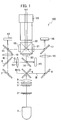
FIG. 1 is a view illustrating an overall configuration example of a projection type image display device according to one or more embodiments. -
FIG. 2 is a side view of a first fly-eye lens, a second fly-eye lens, and a polarized light conversion element when viewed from the side. -
FIG. 3 is a top view of the first fly-eye lens 2, the second fly-eye lens, and the polarized light conversion element when viewed from the top. -
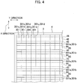
FIG. 4 is a plan view illustrating a state where the second fly-eye lens and the polarized light conversion element are viewed from the side of the second fly-eye lens. -
FIG. 5 is a view illustrating the action of the polarized light conversion element. - Hereinafter, a projection type image display device according to one or more embodiments will be described with reference to the accompanying drawings. First, an overall configuration and operation of a projection type
image display device 100 which is a configuration example of the projection type image display device according to one or more embodiments will be described with reference toFIG. 1 . - In
FIG. 1 , a light source 1 emits white light. As an example, the light source 1 is an ultra-high-pressure mercury lamp. The white light is an indefinite polarized light including P-polarized light and S-polarized light. A type of the light source 1 is not limited, and a light emitting diode (LED) or a laser diode may be used as the light source 1. Depending on the type of the light source 1, the light source 1 may emit light of a color other than white. - The white light is irradiated on a first fly-
eye lens 2. The first fly-eye lens 2 has a structure in which a plurality of rectangular lens cells are arranged in a matrix shape in a first direction and in a second direction orthogonal to the first direction in a plane. The first and second directions respectively correspond to a horizontal direction (X direction) and a vertical direction (Y direction) of an image to be projected by the projection typeimage display device 100. The first fly-eye lens 2 divides the luminous flux of the irradiated white light into partial luminous fluxes for each lens cell. - Each partial luminous flux emitted from the first fly-
eye lens 2 is irradiated on a second fly-eye lens 3. In the same manner as that of the first fly-eye lens 2, the second fly-eye lens 3 has a structure in which a plurality of rectangular lens cells are arranged in a matrix shape in the X direction and Y direction in a plane. Each lens cell of the second fly-eye lens 3 corresponds to each lens cell of the first fly-eye lens 2 by one to one. Each lens cell of the second fly-eye lens 3 individually condenses each partial luminous flux emitted from each lens cell of the first fly-eye lens 2. - Each lens cell is eccentric such that the partial luminous fluxes emitted from the respective lens cells of the second fly-
eye lens 3 are condensed and the respective partial luminous fluxes are superimposed on each other. A degree of eccentricity of each lens cell of the second fly-eye lens 3 varies depending on a position of the lens cell. The second fly-eye lens 3 is configured in such a manner that, in the X direction and the Y direction, a step difference exists at a boundary between the lens cells adjacent to each other in one direction and a step difference does not exist at a boundary between the lens cells adjacent to each other in the other direction. - In
FIG. 1 , the number of lens cells of the first fly-eye lens 2 and the second fly-eye lens 3 is reduced to simplify the drawing. The number and shape of the lens cells of the first fly-eye lens 2 and the second fly-eye lens 3 will be described in detail later. - The partial luminous flux emitted from each lens cell of the second fly-
eye lens 3 is irradiated on a polarizedlight conversion element 4. In order to use the first polarized light that is one of the P-polarized light and S-polarized light included in each partial luminous flux as illumination light, the polarizedlight conversion element 4 converts the second polarized light that is the other of the P-polarized light and S-polarized light and is not used as illumination light into the first polarized light. For example, in one or more embodiments, the first polarized light is the S-polarized light and the second polarized light is the P-polarized light. - The polarized
light conversion element 4 mainly emits the S-polarized light by converting the P-polarized light into the S-polarized light, but may emit the P-polarized light by converting the S-polarized light into the P-polarized light. - A specific configuration and action of the polarized
light conversion element 4 will be described later. In one or more embodiments, the S-polarized light as polarized light at the time of being irradiated on the second fly-eye lens 3 is used as the illumination light, but the P-polarized light may be configured to be used as the illumination light. - The light mainly formed of the S-polarized light emitted from the polarized
light conversion element 4 is incident on a cross dichroic mirror 6, in a state where the light is condensed by a condensing action performed by the second fly-eye lens 3 and the respective partial luminous fluxes are superimposed on each other. If each lens cell of the second fly-eye lens 3 is not eccentric and each lens cell does not perform the condensing action, acondenser lens 5 as indicated by a two-dash chain line is required in a rear stage of the polarizedlight conversion element 4. Thecondenser lens 5 can be configured to be omitted by causing each lens cell of the second fly-eye lens 3 to be eccentric. - The cross dichroic mirror 6 separates the incident light into red light (hereinafter referred to as R light), green light (hereinafter referred to as G light), and blue light (hereinafter referred to as B light). The R light and the G light are reflected by a reflection mirror 7 such that a traveling direction of the R light and the G light is bent by 90 degrees, after which the R light and the G light is directed to a
dichroic mirror 9. The B light is reflected by a reflection mirror 8 such that a traveling direction of the B light is bent by 90 degrees, after which the B light is directed to afield lens 16. - The R light out of the R light and the G light is transmitted through the
dichroic mirror 9 and is directed to afield lens 10. The G light is reflected by thedichroic mirror 9 such that the traveling direction of the G light is bent by 90 degrees, after which the G light is directed to afield lens 13. Thefield lenses - The R light transmitted through the
field lens 10 is transmitted through a polarizingplate 11 and is incident on a redimage display element 12. As an example, thepolarizing plate 11, andpolarizing plates image display element 12, and a greenimage display element 15 and a blueimage display element 18 which will be described later are reflection type liquid crystal display elements. Typically, the reflection type liquid crystal display element is a spatial light modulation element referred to as LCOS (Liquid Crystal On Silicon). - The red
image display element 12 modulates and reflects the R light according to a red component of an image to be projected. The redimage display element 12 modulates the R light, thereby converting the S-polarized light into the P-polarized light. Accordingly, the modulated light of the R light reflected by the redimage display element 12 is reflected by thepolarizing plate 11 such that the traveling direction of the modulated light of the R light is bent by 90 degrees, after which the modulated light thereof is directed to apolarizing plate 19 stuck to acolor combining prism 22. - The G light is transmitted through the
field lens 13 and thepolarizing plate 14, and then is incident on the greenimage display element 15. The greenimage display element 15 modulates and reflects the G light according to a green component of the image to be projected. The greenimage display element 15 modulates the G light, thereby converting the S-polarized light into the P-polarized light. Accordingly, the modulated light of the G light reflected by the greenimage display element 15 is reflected by thepolarizing plate 14 such that the traveling direction of the modulated light of the G light is bent by 90 degrees, after which the modulated light thereof is directed to apolarizing plate 20 stuck to thecolor combining prism 22. - The B light is transmitted through the
field lens 16 and thepolarizing plate 17, and then is incident on the blueimage display element 18. The blueimage display element 18 modulates and reflects the B light according to a blue component of the image to be projected. The blueimage display element 18 modulates the B light, thereby converting the S-polarized light into the P-polarized light. Accordingly, the modulated light of the B light reflected by the blueimage display element 18 is reflected by thepolarizing plate 17 such that the traveling direction of the modulated light of the B light is bent by 90 degrees, after which the modulated light thereof is directed to apolarizing plate 21 stuck to thecolor combining prism 22. As an example, thepolarizing plates - The
polarizing plates color combining prism 22. Thecolor combining prism 22 performs the color combination of the R light, the G light, and the B light, and then emits the combined light toward aprojection lens 23. Theprojection lens 23 enlarges and projects the combined light on an unillustrated screen. As described above, the projection typeimage display device 100 displays the image on the screen. - Structures of the first fly-
eye lens 2, the second fly-eye lens 3, the polarizedlight conversion element 4, and the relationship between the second fly-eye lens 3 and the polarizedlight conversion element 4 will be described with reference toFIGS. 2 and3 .FIG. 2 illustrates a state in which the first fly-eye lens 2, the second fly-eye lens 3, and the polarizedlight conversion element 4 are viewed from the side. In one or more embodiments, light emitted from each lens cell of the second fly-eye lens 3 and superimposed on each other is configured to be rotated by 90 degrees and to be projected on the screen. Accordingly, a height direction of when the first fly-eye lens 2, the second fly-eye lens 3, and the polarizedlight conversion element 4 are viewed from the side is the X direction. - As illustrated in
FIG. 2 , for example, 8 pieces of lens cells 201 (first lens cells) are arranged in the X direction in the first fly-eye lens 2. Thelens cell 201 is a convex lens and is not eccentric. The 8 pieces oflens cells 201 have the same height. In the second fly-eye lens 3, 8 pieces of lens cells 301 (second lens cells) are arranged in the X direction so as to correspond to therespective lens cells 201. Thelens cell 301 is a convex lens and is eccentric in the X direction. - More specifically, the
lens cell 301 positioned above the center in the X direction indicated by a one-dash chain line is eccentric downward, and thelens cell 301 positioned below the center is eccentric upward. That is, thelens cell 301 positioned thereabove and thelens cell 301 positioned therebelow are mutually eccentric to the center side in the X direction. A degree of eccentricity of thelens cell 301 becomes large as thelens cell 301 goes from the center toward an upper end portion or a lower end portion. 8 pieces oflens cells 301 have the same height. - The lower end portion of the surface of each
lens cell 301 of the plurality oflens cells 301 arranged in the X direction is defined as 301a and the upper end portion thereof is defined as 301b. Theend portion 301a and theend portion 301b of twolens cells 301 adjacent to each other in the X direction do not coincide with each other and are deviated in the thickness direction of the second fly-eye lens 3. That is, a step difference exists at a boundary between twolens cells 301 adjacent to each other. Note that there is no step difference at a boundary between twolens cells 301 sandwiching the center in the X direction indicated by the one-dash chain line. -
FIG. 3 illustrates a state in which the first fly-eye lens 2, the second fly-eye lens 3, and the polarizedlight conversion element 4 are viewed from the top. A width direction of when the first fly-eye lens 2, the second fly-eye lens 3, and the polarizedlight conversion element 4 are viewed from the top is the Y direction. - As illustrated in
FIG. 3 , for example, 14 pieces oflens cells 201 are arranged in the Y direction of the first fly-eye lens 2. In the second fly-eye lens lens cells 301 are arranged in the Y direction so as to correspond to therespective lens cells 201. Thelens cell 301 is eccentric in the Y direction. - More specifically, the
lens cell 301 positioned on one side (upper portion ofFIG. 3 ) with respect to the center in the Y direction indicated by a one-dash chain line is eccentric to the other side (lower portion ofFIG. 3 ), and thelens cell 301 positioned on the other side (lower portion ofFIG. 3 ) with respect to the center is eccentric to one side (upper portion ofFIG. 3 ). That is, thelens cell 301 positioned on one side and thelens cell 301 positioned on the other side are mutually eccentric to the center side in the Y direction. A degree of eccentricity of thelens cell 301 becomes large as thelens cell 301 goes from the center to the end portion in the Y direction. Heights of the 14 pieces oflens cells 301 increase in order from the end portion in the Y direction to the center. - The lower end portion of
FIG. 3 of the surface of eachlens cell 301 of the plurality oflens cells 301 arranged in the Y direction is defined as 301c and the upper end portion thereof is defined as 301d. Theend portion 301c and theend portion 301d of twolens cells 301 adjacent to each other in the Y direction coincide with each other and are not deviated in the thickness direction of the second fly-eye lens 3. That is, in the Y direction, there is no step difference at a boundary between twolens cells 301 adjacent to each other. - Returning to
FIG. 2 , areflection surface 41 indicated by a solid line and a polarizedlight separation surface 42 indicated by a broken line are alternately formed in the X direction on the inside of the polarizedlight conversion element 4. Thereflection surface 41 and the polarizedlight separation surface 42 are formed so as to have a predetermined angle with respect to an incident surface of light of the polarizedlight conversion element 4. The predetermined angle is desirably 45 degrees. In one or more embodiments, thereflection surface 41 reflects the incident light, and the polarizedlight separation surface 42 transmits the P-polarized light and reflects the S-polarized light. - Regions sandwiched between the
reflection surface 41 and the polarizedlight separation surface 42 are defined asregions region 43 and theregion 44 in the X direction is the same. The size of eachlens cell 301 in the X direction is the same as the distance in the X direction obtained by combining theregions wavelength plate 45 is stuck to a portion of eachregion 44 on a light emission surface of the polarizedlight conversion element 4. The distance in the X direction of the 1/2wavelength plate 45 is 1/2 of the size of thelens cell 301 in the X direction. - The 1/2
wavelength plate 45 is stuck to the portion of eachregion 44 on the light emission surface of the polarizedlight conversion element 4, and theregion 44 is referred to as the polarizedlight conversion region 44. The 1/2wavelength plate 45 is not stuck to a portion of eachregion 43 on the light emission surface of the polarizedlight conversion element 4, and theregion 43 is referred to as the non-polarizedlight conversion region 43. The non-polarizedlight conversion region 43 and the polarizedlight conversion region 44 are alternately formed in the X direction at an interval of 1/2 of the size of thelens cell 301 in the X direction in the polarizedlight conversion element 4. -
FIG. 4 illustrates a state in which the second fly-eye lens 3 and the polarizedlight conversion element 4 are viewed from the side of the second fly-eye lens 3. The positions of the non-polarizedlight conversion region 43 of the polarizedlight conversion element 4 and the polarizedlight conversion region 44 thereof inFIG. 4 indicate the positions on the light emission surface of the polarizedlight conversion element 4. The 1/2wavelength plate 45 is opposite to the plurality oflens cells 301 arranged in the Y direction. - In
FIG. 4 , theend portions lens cells 301 adjacent to each other in the X direction have the step difference, and a state of the step difference is indicated by a thick solid line. The step difference of the boundary indicated by the thick solid line is opposite to the non-polarizedlight conversion region 43 to which the 1/2wavelength plate 45 is not stuck. On the other hand, theend portions lens cells 301 adjacent to each other in the Y direction do not have the step difference, and intersect the 1/2wavelength plate 45. - An action of the polarized
light conversion element 4 will be described with reference toFIG. 5 . InFIG. 5 , partial luminous flux including the P-polarized light and the S-polarized light emitted from eachlens cell 201 of the first fly-eye lens 2 is incident on eachlens cell 301 of the second fly-eye lens 3. Among the light incident on thelens cells 301, central light L1 transmitted through a central portion of thelens cell 301 in the X direction and peripheral light L2 transmitted through a peripheral portion near the boundary are separately considered. - Which range of the
lens cell 301 in the X direction is defined as the central portion and which range is defined as the peripheral portion can be a design matter. - As illustrated in
FIG. 5 , the P-polarized light out of the P-polarized light and the S-polarized light included in the central light L1 is transmitted through the polarizedlight separation surface 42 and is incident on the 1/2wavelength plate 45. Since the 1/2wavelength plate 45 converts the P-polarized light into the S-polarized light, the S-polarized light is emitted from the polarizedlight conversion region 44. The S-polarized light out of the P-polarized light and the S-polarized light included in the central light L1 is reflected by the polarizedlight separation surface 42 such that the traveling direction of the S-polarized light is bent by 90 degrees, after which the S-polarized light is further reflected by thereflection surface 41 and the traveling direction thereof is bent by 90 degrees, such that the S-polarized light is emitted from the non-polarizedlight conversion region 43. - The P-polarized light and the S-polarized light included in the peripheral light L2 are reflected by the
reflection surface 41 such that the traveling directions of the P-polarized light and the S-polarized light are bent by 90 degrees, after which the P-polarized light and the S-polarized light are incident on the polarizedlight separation surface 42. The P-polarized light out of the P-polarized light and the S-polarized light which are incident on the polarizedlight separation surface 42 is transmitted through the polarizedlight separation surface 42 and then is incident on theother reflection surface 41. The other reflection surface 41 is thenext reflection surface 41 on which the P-polarized light transmitted through the polarizedlight separation surface 42 is incident. The P-polarized light incident on thereflection surface 41 is reflected by thereflection surface 41 and the traveling direction thereof is bent by 90 degree, such that the P-polarized light is emitted from the non-polarizedlight conversion region 43. - The S-polarized light out of the P-polarized light and the S-polarized light incident on the polarized
light separation surface 42 is reflected by the polarizedlight separation surface 42 such that the traveling direction of the S-polarized light is bent by 90 degrees, after which the S-polarized light is incident on the 1/2wavelength plate 45. Since the 1/2wavelength plate 45 converts the S-polarized light into the P-polarized light, the P-polarized light is emitted from the polarizedlight conversion region 44. - As described above, in the second fly-
eye lens 3, the step difference exists at the boundary (first boundary) between twolens cells 301 adjacent to each other in the X direction, whereas the step difference does not exist at the boundary (second boundary) between twolens cells 301 adjacent to each other in the Y direction. Since only the boundary between thelens cells 301 adjacent to each other in the Y direction does not have the step difference, a change in the size of the illumination range by eachlens cell 301 can be minimized. - Therefore, the size of the illumination range by each
lens cell 301 is almost the same as the size of the illumination range in a shape having the step differences at the boundaries in the X direction and the Y direction, and the brightness of the light emitted from therespective lens cells 301 and superimposed on each other is unlikely to become uneven in the plane. - As described in
FIG. 5 , the polarizedlight conversion element 4 emits the P-polarized light based upon the peripheral light L2 transmitted through the peripheral portion near the boundary of thelens cell 301 in the X direction. However, the P-polarized light is not used as the illumination light, even though there is a shape error of "sagging" or "chipping" at the end portion of thelens cell 301, the quality of the image to be projected on the screen is not adversely affected. - As illustrated in
FIG. 4 , even though the boundary of thelens cell 301 in the Y direction is opposite to intersect the 1/2wavelength plate 45, there is no step difference at the boundary of thelens cell 301 adjacent in the Y direction. Therefore, the peripheral light transmitted through the peripheral portion near the boundary of thelens cell 301 in the Y direction also does not adversely affect the quality of the image to be projected on the screen. - In one or more embodiments, the plurality of
lens cells 301 are eccentric in both the X direction and Y direction such that the respective partial luminous fluxes emitted from therespective lens cells 301 are superimposed on each other. Therefore, the projection typeimage display device 100 does not require thecondenser lens 5 for superimposing the respective partial luminous fluxes on the rear stage of the polarizedlight conversion element 4. The number of components can be reduced by a configuration in which thecondenser lens 5 is omitted, and the brightness is not reduced by allowing the light to be transmitted through thecondenser lens 5. - As described above, in accordance with the projection type image display device according to one or more embodiments, it is possible not only to minimize the change in the size of the illumination range by each lens cell of the fly-eye lens, but also to avoid the adverse effect on the image quality caused by the step difference existing at the boundary between the lens cells adjacent to each other.
- The present invention is not limited to one or more embodiments described above, and various modifications can be made within a range not departing from the scope of the present invention. The projection type image display device of the present disclosure may be configured to include a pair of fly-eye lenses and a polarized light conversion element, and the configuration of the rear stage of the polarized light conversion element is not particularly limited.
Claims (2)
- A projection type image display device, comprising:a first fly-eye lens (2) configured to include a plurality of first lens cells (201) arranged in a first direction and a second direction orthogonal to the first direction, and to divide an incident luminous flux into partial luminous fluxes for the respective first lens cells (201) ;a second fly-eye lens (3) configured to include a plurality of second lens cells (301) arranged in the first direction and the second direction, and to individually condense the respective partial luminous fluxes emitted from the respective first lens cells (201) by the respective second lens cells (301); anda polarized light conversion element (4) configured to emit a first polarized light used as illumination light, and to convert a second polarized light not used as the illumination light into the first polarized light to emit the converted first polarized light, out of the first polarized light and the second polarized light included in the light incident from the second fly-eye lens (3), whereinin the polarized light conversion element (4), a reflection surface (41) including a predetermined angle with respect to an incident surface of the light incident from the second fly-eye lens (3) and reflecting the incident light and a polarized light separation surface (42) including the predetermined angle, reflecting the first polarized light included in the incident light, and transmitting the second polarized light are alternately formed in the first direction at an interval of 1/2 of a size of the second lens cell (301) in the first direction,a region sandwiched between the reflection surface (41) and the polarized light separation surface (42) on a light emission surface of the polarized light conversion element (4) is alternately formed with a polarized light conversion region to which a 1/2 wavelength plate (45) is stuck and a non-polarized light conversion region to which the 1/2 wavelength plate (45) is not stuck in the first direction,the 1/2 wavelength plate (45) is opposite to the plurality of the second lens cells (301) arranged in the second direction,the plurality of the second lens cells are respectively eccentric in the first and second directions,end portions of two second lens cells (301) at a first boundary between the two second lens cells (301) adjacent to each other in the first direction are deviated in the thickness direction of the second fly-eye lens (3), such that a step difference exists at the first boundary,end portions of two second lens cells (301) at a second boundary between the two second lens cells (301) adjacent to each other in the second direction coincide with each other in the thickness direction of the second fly-eye lens (3), such that a step difference does not exist at the second boundary,central light transmitted through a central portion of the second lens cell in the first direction is incident on the polarized light separation surface (42), and the polarized light separation surface (42) reflects the first polarized light included in the central light and transmits the second polarized light,the reflection surface (41) on which the first polarized light reflected by the polarized light separation surface (42) is incident reflects the first polarized light and causes the polarized light conversion element (4) to emit the reflected first polarized light, and the 1/2 wavelength plate (45) on which the second polarized light transmitted through the polarized light separation surface (42) is incident converts the second polarized light into the first polarized light and causes the polarized light conversion element (4) to emit the converted first polarized light,peripheral light transmitted through a peripheral portion near the first boundary between the second lens cells (301) is incident on the reflection surface (41) and the reflection surface (41) reflects the peripheral light, and the polarized light separation surface (42) on which the peripheral light reflected by the reflection surface (41) is incident reflects the first polarized light included in the peripheral light and transmits the second polarized light, andthe 1/2 wavelength plate (45) on which the first polarized light reflected by the polarized light separation surface (42) is incident converts the first polarized light into the second polarized light and causes the polarized light conversion element (4) to emit the converted second polarized light, and the other reflection surface (41) on which the second polarized light transmitted through the polarized light separation surface (42) is incident reflects the second polarized light and causes the polarized light conversion element (4) to emit the reflected second polarized light.
- The projection type image display device according to claim 1, wherein
the plurality of the second lens cells (301) are respectively eccentric in the first and second directions such that the respective partial luminous fluxes emitted from the respective second lens cells (301) are superimposed on each other.
Applications Claiming Priority (1)
| Application Number | Priority Date | Filing Date | Title |
|---|---|---|---|
| JP2018160324A JP7052644B2 (en) | 2018-08-29 | 2018-08-29 | Projection type image display device |
Publications (2)
| Publication Number | Publication Date |
|---|---|
| EP3620832A1 true EP3620832A1 (en) | 2020-03-11 |
| EP3620832B1 EP3620832B1 (en) | 2021-04-07 |
Family
ID=67777223
Family Applications (1)
| Application Number | Title | Priority Date | Filing Date |
|---|---|---|---|
| EP19194131.9A Active EP3620832B1 (en) | 2018-08-29 | 2019-08-28 | Projection type image display device |
Country Status (4)
| Country | Link |
|---|---|
| US (1) | US11079667B2 (en) |
| EP (1) | EP3620832B1 (en) |
| JP (1) | JP7052644B2 (en) |
| CN (1) | CN110873997B (en) |
Citations (11)
| Publication number | Priority date | Publication date | Assignee | Title |
|---|---|---|---|---|
| EP1031870A2 (en) * | 1999-02-23 | 2000-08-30 | Seiko Epson Corporation | Illumination system and projector |
| US6204972B1 (en) * | 1997-03-28 | 2001-03-20 | Seiko Epson Corporation | Illumination optical system and projection-type display apparatus |
| US6257726B1 (en) * | 1997-02-13 | 2001-07-10 | Canon Kabushiki Kaisha | Illuminating apparatus and projecting apparatus |
| US6273569B1 (en) * | 1998-12-25 | 2001-08-14 | Seiko Epson Corporation | Illuminating optical system and projector |
| JP2002023108A (en) | 2000-07-06 | 2002-01-23 | Seiko Epson Corp | Illumination optical system and projector having the same |
| US6527393B1 (en) * | 1999-07-28 | 2003-03-04 | Seiko Epson Corporation | Illumination optical system and projector using same |
| US6542298B1 (en) * | 1999-06-21 | 2003-04-01 | Seiko Epson Corporation | Method for manufacturing a polarization beam splitter |
| US6552760B1 (en) * | 1999-02-18 | 2003-04-22 | Fujitsu Limited | Luminaire with improved light utilization efficiency |
| US20030197937A1 (en) * | 2002-03-28 | 2003-10-23 | Seiko Epson Corporation | Polarization converter, an illumination optical device having the polarization converter and projector |
| JP2003337378A (en) * | 2002-03-15 | 2003-11-28 | Seiko Epson Corp | Integrator illumination optical system and projector having the same |
| JP2007078731A (en) | 2005-09-09 | 2007-03-29 | Sanyo Electric Co Ltd | Projector device |
Family Cites Families (13)
| Publication number | Priority date | Publication date | Assignee | Title |
|---|---|---|---|---|
| TW561296B (en) * | 1996-10-30 | 2003-11-11 | Seiko Epson Corp | Projection display and its illuminating optical system |
| JP3666339B2 (en) | 2000-01-28 | 2005-06-29 | セイコーエプソン株式会社 | projector |
| JP2002023105A (en) * | 2000-07-04 | 2002-01-23 | Seiko Epson Corp | Illumination optical system and projector using the same |
| US7222967B2 (en) * | 2001-08-10 | 2007-05-29 | Canon Kabushiki Kaisha | Image display optical system and projection type image display apparatus |
| JP4539319B2 (en) * | 2004-12-15 | 2010-09-08 | 株式会社日立製作所 | Projection display |
| JP4652112B2 (en) * | 2005-04-26 | 2011-03-16 | 富士フイルム株式会社 | Projection display |
| JP2007025308A (en) * | 2005-07-19 | 2007-02-01 | Hitachi Ltd | Projection-type image display device and color separation unit |
| JP5361145B2 (en) * | 2006-06-08 | 2013-12-04 | キヤノン株式会社 | Illumination optical system, image projection optical system, and image projection apparatus |
| US20110051093A1 (en) | 2009-08-26 | 2011-03-03 | Butterfly Technology (Shenzhen) Limited | Polarization conversion apparatus and projection system using same |
| JP5625932B2 (en) * | 2010-02-19 | 2014-11-19 | 株式会社Jvcケンウッド | Projection display |
| JP6202529B2 (en) * | 2011-07-05 | 2017-09-27 | 国立大学法人東京農工大学 | 3D display device |
| JP2013044800A (en) * | 2011-08-22 | 2013-03-04 | Sony Corp | Illumination device and display device |
| JP2016075778A (en) * | 2014-10-06 | 2016-05-12 | セイコーエプソン株式会社 | Light source device and projector |
-
2018
- 2018-08-29 JP JP2018160324A patent/JP7052644B2/en active Active
-
2019
- 2019-07-10 CN CN201910619204.6A patent/CN110873997B/en active Active
- 2019-07-15 US US16/511,302 patent/US11079667B2/en active Active
- 2019-08-28 EP EP19194131.9A patent/EP3620832B1/en active Active
Patent Citations (11)
| Publication number | Priority date | Publication date | Assignee | Title |
|---|---|---|---|---|
| US6257726B1 (en) * | 1997-02-13 | 2001-07-10 | Canon Kabushiki Kaisha | Illuminating apparatus and projecting apparatus |
| US6204972B1 (en) * | 1997-03-28 | 2001-03-20 | Seiko Epson Corporation | Illumination optical system and projection-type display apparatus |
| US6273569B1 (en) * | 1998-12-25 | 2001-08-14 | Seiko Epson Corporation | Illuminating optical system and projector |
| US6552760B1 (en) * | 1999-02-18 | 2003-04-22 | Fujitsu Limited | Luminaire with improved light utilization efficiency |
| EP1031870A2 (en) * | 1999-02-23 | 2000-08-30 | Seiko Epson Corporation | Illumination system and projector |
| US6542298B1 (en) * | 1999-06-21 | 2003-04-01 | Seiko Epson Corporation | Method for manufacturing a polarization beam splitter |
| US6527393B1 (en) * | 1999-07-28 | 2003-03-04 | Seiko Epson Corporation | Illumination optical system and projector using same |
| JP2002023108A (en) | 2000-07-06 | 2002-01-23 | Seiko Epson Corp | Illumination optical system and projector having the same |
| JP2003337378A (en) * | 2002-03-15 | 2003-11-28 | Seiko Epson Corp | Integrator illumination optical system and projector having the same |
| US20030197937A1 (en) * | 2002-03-28 | 2003-10-23 | Seiko Epson Corporation | Polarization converter, an illumination optical device having the polarization converter and projector |
| JP2007078731A (en) | 2005-09-09 | 2007-03-29 | Sanyo Electric Co Ltd | Projector device |
Also Published As
| Publication number | Publication date |
|---|---|
| JP7052644B2 (en) | 2022-04-12 |
| US11079667B2 (en) | 2021-08-03 |
| CN110873997B (en) | 2022-04-05 |
| US20200073222A1 (en) | 2020-03-05 |
| CN110873997A (en) | 2020-03-10 |
| EP3620832B1 (en) | 2021-04-07 |
| JP2020034678A (en) | 2020-03-05 |
Similar Documents
| Publication | Publication Date | Title |
|---|---|---|
| CN111752081B (en) | Light source device, projector and light source module | |
| JP5605866B2 (en) | Illumination optical system and projection display device including the same | |
| CN109725482B (en) | X-shaped adjustment module and light combining device and projector using the X-shaped adjustment module | |
| US6273569B1 (en) | Illuminating optical system and projector | |
| CN1204419C (en) | Integrated lamp optical system and projector with the system | |
| JPWO2011045857A1 (en) | Illumination device and projection display device using the same | |
| JP6078976B2 (en) | projector | |
| JP6278489B2 (en) | Projection display | |
| JP4475289B2 (en) | projector | |
| CN112987470A (en) | Light source device and projector | |
| JP2009063892A (en) | Projector, optical element, and light modulation device | |
| EP3620832B1 (en) | Projection type image display device | |
| JP5707984B2 (en) | projector | |
| JPWO2010086984A1 (en) | Projection display | |
| JP5311519B2 (en) | Illumination device and projection display device using the same | |
| JP4893780B2 (en) | LIGHTING DEVICE AND PROJECTOR HAVING THE SAME | |
| JP6436514B2 (en) | Projection display | |
| JP6532344B2 (en) | Illumination optical system and projection type display apparatus using the same | |
| JP2013007835A (en) | Projection type video display apparatus | |
| JP4798255B2 (en) | projector | |
| JP4487484B2 (en) | LIGHTING DEVICE AND PROJECTOR HAVING THE SAME | |
| JP5924244B2 (en) | Liquid crystal display device and projection display device | |
| JP4066992B2 (en) | Illumination optical system and projection display device | |
| JP6225555B2 (en) | projector | |
| JP2020204630A (en) | Projection type display device |
Legal Events
| Date | Code | Title | Description |
|---|---|---|---|
| PUAI | Public reference made under article 153(3) epc to a published international application that has entered the european phase |
Free format text: ORIGINAL CODE: 0009012 |
|
| STAA | Information on the status of an ep patent application or granted ep patent |
Free format text: STATUS: THE APPLICATION HAS BEEN PUBLISHED |
|
| AK | Designated contracting states |
Kind code of ref document: A1 Designated state(s): AL AT BE BG CH CY CZ DE DK EE ES FI FR GB GR HR HU IE IS IT LI LT LU LV MC MK MT NL NO PL PT RO RS SE SI SK SM TR |
|
| AX | Request for extension of the european patent |
Extension state: BA ME |
|
| STAA | Information on the status of an ep patent application or granted ep patent |
Free format text: STATUS: REQUEST FOR EXAMINATION WAS MADE |
|
| 17P | Request for examination filed |
Effective date: 20200911 |
|
| RBV | Designated contracting states (corrected) |
Designated state(s): AL AT BE BG CH CY CZ DE DK EE ES FI FR GB GR HR HU IE IS IT LI LT LU LV MC MK MT NL NO PL PT RO RS SE SI SK SM TR |
|
| RIC1 | Information provided on ipc code assigned before grant |
Ipc: G03B 21/20 20060101ALI20201030BHEP Ipc: H04N 13/307 20180101ALI20201030BHEP Ipc: G02B 3/00 20060101AFI20201030BHEP Ipc: H04N 9/31 20060101ALI20201030BHEP Ipc: G03F 7/20 20060101ALI20201030BHEP Ipc: G02B 27/09 20060101ALI20201030BHEP Ipc: G02B 27/28 20060101ALI20201030BHEP |
|
| GRAP | Despatch of communication of intention to grant a patent |
Free format text: ORIGINAL CODE: EPIDOSNIGR1 |
|
| STAA | Information on the status of an ep patent application or granted ep patent |
Free format text: STATUS: GRANT OF PATENT IS INTENDED |
|
| INTG | Intention to grant announced |
Effective date: 20201211 |
|
| GRAS | Grant fee paid |
Free format text: ORIGINAL CODE: EPIDOSNIGR3 |
|
| GRAA | (expected) grant |
Free format text: ORIGINAL CODE: 0009210 |
|
| STAA | Information on the status of an ep patent application or granted ep patent |
Free format text: STATUS: THE PATENT HAS BEEN GRANTED |
|
| AK | Designated contracting states |
Kind code of ref document: B1 Designated state(s): AL AT BE BG CH CY CZ DE DK EE ES FI FR GB GR HR HU IE IS IT LI LT LU LV MC MK MT NL NO PL PT RO RS SE SI SK SM TR |
|
| REG | Reference to a national code |
Ref country code: GB Ref legal event code: FG4D |
|
| REG | Reference to a national code |
Ref country code: AT Ref legal event code: REF Ref document number: 1380422 Country of ref document: AT Kind code of ref document: T Effective date: 20210415 Ref country code: CH Ref legal event code: EP |
|
| REG | Reference to a national code |
Ref country code: DE Ref legal event code: R096 Ref document number: 602019003753 Country of ref document: DE |
|
| REG | Reference to a national code |
Ref country code: IE Ref legal event code: FG4D |
|
| REG | Reference to a national code |
Ref country code: LT Ref legal event code: MG9D |
|
| REG | Reference to a national code |
Ref country code: NL Ref legal event code: MP Effective date: 20210407 Ref country code: AT Ref legal event code: MK05 Ref document number: 1380422 Country of ref document: AT Kind code of ref document: T Effective date: 20210407 |
|
| PG25 | Lapsed in a contracting state [announced via postgrant information from national office to epo] |
Ref country code: FI Free format text: LAPSE BECAUSE OF FAILURE TO SUBMIT A TRANSLATION OF THE DESCRIPTION OR TO PAY THE FEE WITHIN THE PRESCRIBED TIME-LIMIT Effective date: 20210407 Ref country code: HR Free format text: LAPSE BECAUSE OF FAILURE TO SUBMIT A TRANSLATION OF THE DESCRIPTION OR TO PAY THE FEE WITHIN THE PRESCRIBED TIME-LIMIT Effective date: 20210407 Ref country code: LT Free format text: LAPSE BECAUSE OF FAILURE TO SUBMIT A TRANSLATION OF THE DESCRIPTION OR TO PAY THE FEE WITHIN THE PRESCRIBED TIME-LIMIT Effective date: 20210407 Ref country code: NL Free format text: LAPSE BECAUSE OF FAILURE TO SUBMIT A TRANSLATION OF THE DESCRIPTION OR TO PAY THE FEE WITHIN THE PRESCRIBED TIME-LIMIT Effective date: 20210407 Ref country code: AT Free format text: LAPSE BECAUSE OF FAILURE TO SUBMIT A TRANSLATION OF THE DESCRIPTION OR TO PAY THE FEE WITHIN THE PRESCRIBED TIME-LIMIT Effective date: 20210407 Ref country code: BG Free format text: LAPSE BECAUSE OF FAILURE TO SUBMIT A TRANSLATION OF THE DESCRIPTION OR TO PAY THE FEE WITHIN THE PRESCRIBED TIME-LIMIT Effective date: 20210707 |
|
| PG25 | Lapsed in a contracting state [announced via postgrant information from national office to epo] |
Ref country code: PL Free format text: LAPSE BECAUSE OF FAILURE TO SUBMIT A TRANSLATION OF THE DESCRIPTION OR TO PAY THE FEE WITHIN THE PRESCRIBED TIME-LIMIT Effective date: 20210407 Ref country code: NO Free format text: LAPSE BECAUSE OF FAILURE TO SUBMIT A TRANSLATION OF THE DESCRIPTION OR TO PAY THE FEE WITHIN THE PRESCRIBED TIME-LIMIT Effective date: 20210707 Ref country code: LV Free format text: LAPSE BECAUSE OF FAILURE TO SUBMIT A TRANSLATION OF THE DESCRIPTION OR TO PAY THE FEE WITHIN THE PRESCRIBED TIME-LIMIT Effective date: 20210407 Ref country code: PT Free format text: LAPSE BECAUSE OF FAILURE TO SUBMIT A TRANSLATION OF THE DESCRIPTION OR TO PAY THE FEE WITHIN THE PRESCRIBED TIME-LIMIT Effective date: 20210809 Ref country code: RS Free format text: LAPSE BECAUSE OF FAILURE TO SUBMIT A TRANSLATION OF THE DESCRIPTION OR TO PAY THE FEE WITHIN THE PRESCRIBED TIME-LIMIT Effective date: 20210407 Ref country code: SE Free format text: LAPSE BECAUSE OF FAILURE TO SUBMIT A TRANSLATION OF THE DESCRIPTION OR TO PAY THE FEE WITHIN THE PRESCRIBED TIME-LIMIT Effective date: 20210407 Ref country code: IS Free format text: LAPSE BECAUSE OF FAILURE TO SUBMIT A TRANSLATION OF THE DESCRIPTION OR TO PAY THE FEE WITHIN THE PRESCRIBED TIME-LIMIT Effective date: 20210807 Ref country code: GR Free format text: LAPSE BECAUSE OF FAILURE TO SUBMIT A TRANSLATION OF THE DESCRIPTION OR TO PAY THE FEE WITHIN THE PRESCRIBED TIME-LIMIT Effective date: 20210708 |
|
| REG | Reference to a national code |
Ref country code: DE Ref legal event code: R097 Ref document number: 602019003753 Country of ref document: DE |
|
| PG25 | Lapsed in a contracting state [announced via postgrant information from national office to epo] |
Ref country code: EE Free format text: LAPSE BECAUSE OF FAILURE TO SUBMIT A TRANSLATION OF THE DESCRIPTION OR TO PAY THE FEE WITHIN THE PRESCRIBED TIME-LIMIT Effective date: 20210407 Ref country code: ES Free format text: LAPSE BECAUSE OF FAILURE TO SUBMIT A TRANSLATION OF THE DESCRIPTION OR TO PAY THE FEE WITHIN THE PRESCRIBED TIME-LIMIT Effective date: 20210407 Ref country code: SK Free format text: LAPSE BECAUSE OF FAILURE TO SUBMIT A TRANSLATION OF THE DESCRIPTION OR TO PAY THE FEE WITHIN THE PRESCRIBED TIME-LIMIT Effective date: 20210407 Ref country code: SM Free format text: LAPSE BECAUSE OF FAILURE TO SUBMIT A TRANSLATION OF THE DESCRIPTION OR TO PAY THE FEE WITHIN THE PRESCRIBED TIME-LIMIT Effective date: 20210407 Ref country code: RO Free format text: LAPSE BECAUSE OF FAILURE TO SUBMIT A TRANSLATION OF THE DESCRIPTION OR TO PAY THE FEE WITHIN THE PRESCRIBED TIME-LIMIT Effective date: 20210407 Ref country code: DK Free format text: LAPSE BECAUSE OF FAILURE TO SUBMIT A TRANSLATION OF THE DESCRIPTION OR TO PAY THE FEE WITHIN THE PRESCRIBED TIME-LIMIT Effective date: 20210407 Ref country code: CZ Free format text: LAPSE BECAUSE OF FAILURE TO SUBMIT A TRANSLATION OF THE DESCRIPTION OR TO PAY THE FEE WITHIN THE PRESCRIBED TIME-LIMIT Effective date: 20210407 |
|
| PLBE | No opposition filed within time limit |
Free format text: ORIGINAL CODE: 0009261 |
|
| STAA | Information on the status of an ep patent application or granted ep patent |
Free format text: STATUS: NO OPPOSITION FILED WITHIN TIME LIMIT |
|
| 26N | No opposition filed |
Effective date: 20220110 |
|
| PG25 | Lapsed in a contracting state [announced via postgrant information from national office to epo] |
Ref country code: MC Free format text: LAPSE BECAUSE OF FAILURE TO SUBMIT A TRANSLATION OF THE DESCRIPTION OR TO PAY THE FEE WITHIN THE PRESCRIBED TIME-LIMIT Effective date: 20210407 |
|
| REG | Reference to a national code |
Ref country code: BE Ref legal event code: MM Effective date: 20210831 |
|
| PG25 | Lapsed in a contracting state [announced via postgrant information from national office to epo] |
Ref country code: IS Free format text: LAPSE BECAUSE OF FAILURE TO SUBMIT A TRANSLATION OF THE DESCRIPTION OR TO PAY THE FEE WITHIN THE PRESCRIBED TIME-LIMIT Effective date: 20210807 Ref country code: LU Free format text: LAPSE BECAUSE OF NON-PAYMENT OF DUE FEES Effective date: 20210828 Ref country code: AL Free format text: LAPSE BECAUSE OF FAILURE TO SUBMIT A TRANSLATION OF THE DESCRIPTION OR TO PAY THE FEE WITHIN THE PRESCRIBED TIME-LIMIT Effective date: 20210407 |
|
| PG25 | Lapsed in a contracting state [announced via postgrant information from national office to epo] |
Ref country code: IT Free format text: LAPSE BECAUSE OF FAILURE TO SUBMIT A TRANSLATION OF THE DESCRIPTION OR TO PAY THE FEE WITHIN THE PRESCRIBED TIME-LIMIT Effective date: 20210407 Ref country code: IE Free format text: LAPSE BECAUSE OF NON-PAYMENT OF DUE FEES Effective date: 20210828 Ref country code: FR Free format text: LAPSE BECAUSE OF NON-PAYMENT OF DUE FEES Effective date: 20210831 Ref country code: BE Free format text: LAPSE BECAUSE OF NON-PAYMENT OF DUE FEES Effective date: 20210831 |
|
| REG | Reference to a national code |
Ref country code: CH Ref legal event code: PL |
|
| PG25 | Lapsed in a contracting state [announced via postgrant information from national office to epo] |
Ref country code: LI Free format text: LAPSE BECAUSE OF NON-PAYMENT OF DUE FEES Effective date: 20220831 Ref country code: CH Free format text: LAPSE BECAUSE OF NON-PAYMENT OF DUE FEES Effective date: 20220831 |
|
| PG25 | Lapsed in a contracting state [announced via postgrant information from national office to epo] |
Ref country code: CY Free format text: LAPSE BECAUSE OF FAILURE TO SUBMIT A TRANSLATION OF THE DESCRIPTION OR TO PAY THE FEE WITHIN THE PRESCRIBED TIME-LIMIT Effective date: 20210407 |
|
| PG25 | Lapsed in a contracting state [announced via postgrant information from national office to epo] |
Ref country code: HU Free format text: LAPSE BECAUSE OF FAILURE TO SUBMIT A TRANSLATION OF THE DESCRIPTION OR TO PAY THE FEE WITHIN THE PRESCRIBED TIME-LIMIT; INVALID AB INITIO Effective date: 20190828 |
|
| PG25 | Lapsed in a contracting state [announced via postgrant information from national office to epo] |
Ref country code: MK Free format text: LAPSE BECAUSE OF FAILURE TO SUBMIT A TRANSLATION OF THE DESCRIPTION OR TO PAY THE FEE WITHIN THE PRESCRIBED TIME-LIMIT Effective date: 20210407 |
|
| PG25 | Lapsed in a contracting state [announced via postgrant information from national office to epo] |
Ref country code: TR Free format text: LAPSE BECAUSE OF FAILURE TO SUBMIT A TRANSLATION OF THE DESCRIPTION OR TO PAY THE FEE WITHIN THE PRESCRIBED TIME-LIMIT Effective date: 20210407 |
|
| PG25 | Lapsed in a contracting state [announced via postgrant information from national office to epo] |
Ref country code: MT Free format text: LAPSE BECAUSE OF FAILURE TO SUBMIT A TRANSLATION OF THE DESCRIPTION OR TO PAY THE FEE WITHIN THE PRESCRIBED TIME-LIMIT Effective date: 20210407 |
|
| PGFP | Annual fee paid to national office [announced via postgrant information from national office to epo] |
Ref country code: DE Payment date: 20250702 Year of fee payment: 7 |
|
| PGFP | Annual fee paid to national office [announced via postgrant information from national office to epo] |
Ref country code: GB Payment date: 20250703 Year of fee payment: 7 |