JP2009063892A - Projector, optical element, and optical modulating device - Google Patents
Projector, optical element, and optical modulating device Download PDFInfo
- Publication number
- JP2009063892A JP2009063892A JP2007232829A JP2007232829A JP2009063892A JP 2009063892 A JP2009063892 A JP 2009063892A JP 2007232829 A JP2007232829 A JP 2007232829A JP 2007232829 A JP2007232829 A JP 2007232829A JP 2009063892 A JP2009063892 A JP 2009063892A
- Authority
- JP
- Japan
- Prior art keywords
- light
- sub
- cylindrical lens
- lens
- pixels
- Prior art date
- Legal status (The legal status is an assumption and is not a legal conclusion. Google has not performed a legal analysis and makes no representation as to the accuracy of the status listed.)
- Pending
Links
Images


Abstract
Description
本発明は、プロジェクタ、光学素子及び光変調装置に関する。 The present invention relates to a projector, an optical element, and a light modulation device.
3板式のプロジェクタは白色光を分離し、得られた赤、緑、青の3原色の色光をそれぞれ伝播する光学系(色分離系)と、その色光の強度を変調し画像を形成する液晶パネルをそれぞれ独立に設けており、各色の画像を光学的に重畳(色合成系)してフルカラー表示を行うものである。この3板式のプロジェクタの構成では、白色光源から射出された光を有効に利用でき、色の純度も高いという利点がある。しかし、前述のように色分離系と色合成系が必要なため、光学系の部品点数が多くなってしまい、低コスト化の点で単板式に比べ不利になる。 The three-plate projector separates white light, and the resulting optical system (color separation system) that propagates the three primary colors of red, green, and blue, and a liquid crystal panel that modulates the intensity of the colored light and forms an image Are provided independently, and full-color display is performed by optically superimposing (color combining system) images of the respective colors. The configuration of this three-plate projector has the advantage that the light emitted from the white light source can be used effectively and the color purity is high. However, since the color separation system and the color synthesis system are necessary as described above, the number of parts of the optical system increases, which is disadvantageous compared to the single plate type in terms of cost reduction.
これに対して単板式のプロジェクタは液晶パネルを1枚のみ用いる構成であり、カラーフィルタのR,G,Bの配列によりデルタ配列、ストライプ配列等に分類される。初期の単板式ではカラーフィルターにより色分離を行っていたが、カラーフィルターによる光の吸収、反射により光の利用効率が3板式の1/3程度に低下し、実用上問題があった。 On the other hand, a single-plate projector has a configuration using only one liquid crystal panel, and is classified into a delta arrangement, a stripe arrangement, and the like according to the arrangement of R, G, and B color filters. In the early single plate type, color separation was performed by a color filter, but the light utilization and light reflection by the color filter lowered the light use efficiency to about 1/3 of the three plate type, and there was a problem in practical use.
この問題を解決するために、カラーフィルターを用いずに、白色光源から射出された光を3枚のダイクロイックミラーを用いて色分離する単板式プロジェクタが提案されている(例えば、特許文献1参照。)。
特許文献1に記載の単板式プロジェクタは、白色光を射出する光源と、光源から射出された光の形状を変換する形状変換光学系と、形状変換光学系から射出された光を分離する3枚のダイクロイックミラーと、液晶パネルとを備えている。
この形状変換光学系は、入射した光を水平方向(色分離方向)に収束させる凸シリンドリカルレンズと、入射した光を平行化する凹シリンドリカルレンズとにより構成されている。これにより、形状変換光学系に入射した光は、水平方向にのみ圧縮された平行光に変換される。平行光に変換された光は、角度差をつけて配置された3枚のダイクロイックミラーにより、R(赤色)光、G(緑色)光、B(青色)光に色分離される。色分離された各色光は、異なる角度でマイクロレンズアレイに入射し、液晶パネルの各サブ画素に集光され、変調される。
この種の液晶パネルでは各画素を照明する光の明るさを上げるために、水平方向(色分離方向)の照明のFno.(Fナンバー)を大きくし、垂直方向(色分離方向と直交する方向)の照明Fno.を小さくしている。ここで、Fno.はレンズの焦点距離をレンズの有効口径によって割ることにより得られる値であり、Fno.が小さいほどレンズによって照明される光は明るくなる。
The single-plate projector described in Patent Document 1 includes a light source that emits white light, a shape conversion optical system that converts the shape of light emitted from the light source, and three sheets that separate light emitted from the shape conversion optical system. Dichroic mirror and a liquid crystal panel.
This shape conversion optical system includes a convex cylindrical lens that converges incident light in the horizontal direction (color separation direction) and a concave cylindrical lens that collimates incident light. Thereby, the light incident on the shape converting optical system is converted into parallel light compressed only in the horizontal direction. The light converted into parallel light is color-separated into R (red) light, G (green) light, and B (blue) light by three dichroic mirrors arranged with an angle difference. The color-separated color lights enter the microlens array at different angles, and are condensed and modulated on the sub-pixels of the liquid crystal panel.
In this type of liquid crystal panel, in order to increase the brightness of the light that illuminates each pixel, the Fno. (F number) is increased, and illumination Fno. In the vertical direction (direction orthogonal to the color separation direction). Is made smaller. Here, Fno. Is a value obtained by dividing the focal length of the lens by the effective aperture of the lens. The smaller the is, the brighter the light illuminated by the lens.
しかしながら、上記特許文献1に記載の単板式プロジェクタでは、マイクロレンズアレイは色分離方向の照明Fno.に対応した焦点距離を有しているため、垂直方向のFno.を明るくすると、対応する画素への入射角度が大きくなってしまう。これにより、マイクロレンズアレイにより集光された照明光は画素から外れてしまい、照明効率が低下する。 However, in the single-plate projector described in Patent Document 1, the microlens array has an illumination Fno. In the vertical direction, Fno. If the brightness is increased, the incident angle to the corresponding pixel increases. Thereby, the illumination light condensed by the microlens array deviates from the pixel, and the illumination efficiency is lowered.
本発明は、上記の課題を解決するためになされたものであって、照明効率を向上させることが可能なプロジェクタ、光学素子及び光変調装置を提供することを目的とする。 SUMMARY An advantage of some aspects of the invention is that it provides a projector, an optical element, and a light modulation device capable of improving illumination efficiency.
上記目的を達成するために、本発明は、以下の手段を提供する。
本発明のプロジェクタは、複数種の色光を含む光を射出する光源と、該光源から射出された光を異なる色光ごとに射出方向が異なるように分離する色分離手段と、複数種の色光に対応した複数のサブ画素で構成された1つの画素がアレイ状に配列され、入射した色光ごとに独立して変調可能な光変調手段と、前記色分離手段と前記光変調手段との間の光路上に配置され、入射した光を色光ごとに複数種の前記サブ画素が配列された第一の方向に集光して異なる色光に対応した前記サブ画素に入射させる第1シリンドリカルレンズと、入射した光を前記第一の方向に略直交する第二の方向に集光して前記サブ画素に入射させる第2シリンドリカルレンズとがそれぞれアレイ状に配列されてなるマイクロレンズアレイと、前記光変調手段により変調された光を投射する投射手段とを備え、前記第1シリンドリカルレンズの第一の方向の径は、前記画素の前記第一の方向のピッチと略等しく、前記第2シリンドリカルレンズの第二の方向の径は、前記サブ画素の前記第二の方向のピッチと略等しいことを特徴とする。
In order to achieve the above object, the present invention provides the following means.
The projector according to the present invention supports a light source that emits light including a plurality of types of color light, a color separation unit that separates the light emitted from the light source so that the emission directions are different for different color lights, and a plurality of types of color light. One pixel composed of a plurality of sub-pixels is arranged in an array and can be modulated independently for each incident color light, and on the optical path between the color separation means and the light modulation means A first cylindrical lens that collects incident light in a first direction in which a plurality of types of sub-pixels are arranged for each color light and enters the sub-pixels corresponding to different color lights, and incident light Microlens array in which second cylindrical lenses that are focused in a second direction substantially orthogonal to the first direction and incident on the sub-pixels are arranged in an array, respectively, and modified by the light modulation means. Projecting means for projecting the emitted light, and the diameter of the first cylindrical lens in the first direction is substantially equal to the pitch of the pixels in the first direction, and the second direction of the second cylindrical lens. The diameter of is substantially equal to the pitch of the sub-pixels in the second direction.
本発明に係るプロジェクタでは、光源から射出された光は、色分離手段により色光ごとに分離されてマイクロレンズアレイに入射する。マイクロレンズアレイに入射した各色光は、光変調手段の複数種の色光に対応したサブ画素に集光された後、光変調手段により変調されて、投射手段によって投射される。
ここで、本発明のマイクロレンズアレイの第1シリンドリカルレンズにより、入射した光を光変調手段の第一の方向に集光させ異なる色光に対応した各サブ画素に入射させる。このとき、第1シリンドリカルレンズの第一の方向の径は、画素の第一の方向のピッチと略等しいため、第1シリンドリカルレンズにより、複数種の色光を対向するサブ画素に分離させて効率良く集光させる。また、第2シリンドリカルレンズにより、入射した光を光変調手段の第二の方向に集光させ各サブ画素に入射させる。このとき、第2シリンドリカルレンズの第二の方向の径は、サブ画素の第二の方向のピッチと略等しいため、第2シリンドリカルレンズにより、複数種の色光を集光し、対向するサブ画素に効率良く入射させる。
In the projector according to the present invention, the light emitted from the light source is separated for each color light by the color separation means and enters the microlens array. Each color light incident on the microlens array is condensed on sub-pixels corresponding to a plurality of types of color light of the light modulation means, then modulated by the light modulation means, and projected by the projection means.
Here, with the first cylindrical lens of the microlens array of the present invention, the incident light is condensed in the first direction of the light modulation means and is incident on each subpixel corresponding to different color light. At this time, since the diameter of the first cylindrical lens in the first direction is substantially equal to the pitch in the first direction of the pixels, the first cylindrical lens efficiently separates a plurality of types of color light into opposing sub-pixels. Collect light. Further, the incident light is condensed in the second direction of the light modulation means by the second cylindrical lens and is incident on each sub-pixel. At this time, since the diameter of the second cylindrical lens in the second direction is substantially equal to the pitch of the sub-pixel in the second direction, a plurality of types of color light are condensed by the second cylindrical lens and applied to the opposing sub-pixels. Make it incident efficiently.
したがって、光変調手段のサブ画素の配列方向の第一の方向と第二の方向とに集光する第1,第2シリンドリカルレンズを別々に設けているため、それぞれの方向の焦点距離を別々に設計することができる。すなわち、例えば、第一の方向の照明Fno.を暗くしても、第二の方向において光がサブ画素から外れないように、第2シリンドリカルレンズを第1シリンドリカルレンズに比べて焦点距離を短く設計することできる。これにより、光変調手段の各サブ画素に入射する光の照明効率の低下を抑えることが可能となる。
さらには、色分離手段により色分離された光を第1,第2シリンドリカルレンズにより光変調手段の各サブ画素に集光させているため、例えば、レンチキュラレンズに比べて焦点距離の短いレンズを作製し易くなる。したがって、本発明では、光変調手段のサブ画素のピッチが狭いときに、短い焦点距離を有する所望のレンズを形成することができるため、微細なサブ画素を有する光変調手段に対応可能となる。すなわち、サブ画素のピッチに対応して第2シリンドリカルレンズの焦点距離を短くすることができるため、装置全体の小型化を図ることも可能となる。
なお、サブ画素とは、1画素を構成する最小単位であって、隣接配置された複数のサブ画素で1画素が構成されている。
Therefore, since the first and second cylindrical lenses for condensing in the first direction and the second direction in the arrangement direction of the sub-pixels of the light modulation means are provided separately, the focal lengths in the respective directions are separately set. Can be designed. That is, for example, the illumination Fno. The second cylindrical lens can be designed to have a shorter focal length than the first cylindrical lens so that the light does not deviate from the sub-pixels in the second direction even when dark. Accordingly, it is possible to suppress a decrease in illumination efficiency of light incident on each subpixel of the light modulation unit.
Furthermore, since the light color-separated by the color separation means is condensed on each sub-pixel of the light modulation means by the first and second cylindrical lenses, for example, a lens having a shorter focal length than a lenticular lens is manufactured. It becomes easy to do. Therefore, in the present invention, when the pitch of the sub-pixels of the light modulation unit is narrow, a desired lens having a short focal length can be formed, so that it is possible to deal with the light modulation unit having fine sub-pixels. That is, since the focal length of the second cylindrical lens can be shortened corresponding to the pitch of the sub-pixels, the entire apparatus can be reduced in size.
Note that a sub-pixel is a minimum unit that constitutes one pixel, and one pixel is constituted by a plurality of adjacently arranged sub-pixels.
また、本発明のプロジェクタは、前記第一の方向と前記第二の方向との曲率が異なり、前記光源から射出された光を反射させる反射部と、前記光源と前記色分離手段との間の光路上に配置され、前記第一の方向と前記第二の方向との曲率が異なるレンズ面を有し、前記反射部において反射した光を集光する集光手段とを備えることが好ましい。 In the projector according to the aspect of the invention, the first direction and the second direction may have different curvatures, and a reflection unit that reflects light emitted from the light source may be provided between the light source and the color separation unit. It is preferable to include a condensing unit that is disposed on the optical path, has a lens surface having different curvatures in the first direction and the second direction, and condenses the light reflected by the reflection unit.
本発明に係るプロジェクタでは、光源から射出された光は、反射部により反射される。このとき、反射部の第一の方向と第二の方向との曲率が異なるため、例えば、第一の方向の光束を細くし、第二の方向の光束を太くすることができる。そして、反射部により反射された光は、第一の方向と第二の方向との曲率が異なるレンズ面を有する集光手段により集光されて略平行光となる。集光手段から射出された光は、第1シリンドリカルレンズにより第一の方向に集光され、第2シリンドリカルレンズにより第二の方向に集光され、光変調装置の各サブ画素に入射する。
このように、第一の方向の光束が細く、第二の方向の光束が太い光を光変調装置に入射することができるため、第一の方向の照明のFno.を暗くし、第二の方向の照明のFno.を明るくするレンズの設計が容易になる。
In the projector according to the present invention, the light emitted from the light source is reflected by the reflecting portion. At this time, since the curvatures of the first direction and the second direction of the reflecting portion are different, for example, the light beam in the first direction can be thinned and the light beam in the second direction can be thickened. And the light reflected by the reflection part is condensed by the condensing means which has a lens surface from which the curvature of a 1st direction and a 2nd direction differs, and becomes a substantially parallel light. The light emitted from the condensing means is condensed in the first direction by the first cylindrical lens, condensed in the second direction by the second cylindrical lens, and enters each subpixel of the light modulation device.
In this way, since the light beam in the first direction is thin and the light beam in the second direction is thick, it is possible to enter the light modulation device. In the second direction of illumination Fno. This makes it easier to design a lens that brightens the screen.
また、本発明のプロジェクタは、前記光源側から第1シリンドリカルレンズ、第2シリンドリカルレンズの順に配置されていることが好ましい。 In the projector according to the aspect of the invention, it is preferable that the first cylindrical lens and the second cylindrical lens are arranged in this order from the light source side.
本発明に係るプロジェクタでは、色分離方向である第一の方向の照明Fno.を暗くし、第二の方向の照明Fno.を明るくするため、第一の方向に光を集光させる第1シリンドリカルレンズの焦点距離を長くし、第二の方向に光を集光させる第2シリンドリカルレンズの焦点距離を短くする。これにより、焦点距離が長い第1シリンドリカルレンズを光源側に配置し、焦点距離が短い第2シリンドリカルレンズを光変調手段側に配置することにより、光源から射出された光を第1,第2シリンドリカルレンズにより効率良く集光させることができる。 In the projector according to the present invention, the illumination Fno. In the second direction of illumination Fno. In order to brighten the light, the focal length of the first cylindrical lens that condenses the light in the first direction is lengthened, and the focal length of the second cylindrical lens that condenses the light in the second direction is shortened. Accordingly, the first cylindrical lens having a long focal length is arranged on the light source side, and the second cylindrical lens having a short focal length is arranged on the light modulation means side, whereby the light emitted from the light source is changed to the first and second cylindrical lenses. Light can be efficiently collected by the lens.
また、本発明のプロジェクタは、前記第1シリンドリカルレンズから射出された光の主光軸を前記光変調手段の入射端面に対して略垂直とする第1フィールドレンズと、前記第2シリンドリカルレンズから射出された光の主光軸を前記光変調手段の入射端面に対して略垂直とする第2フィールドレンズとを備え、前記第1フィールドレンズ及び前記第2フィールドレンズはシリンドリカルレンズであることが好ましい。 In the projector according to the aspect of the invention, the first field lens that makes the main optical axis of the light emitted from the first cylindrical lens substantially perpendicular to the incident end surface of the light modulation unit, and the second cylindrical lens. It is preferable that the second field lens has a main optical axis of the light that is substantially perpendicular to the incident end face of the light modulation unit, and the first field lens and the second field lens are cylindrical lenses.
本発明に係るプロジェクタでは、マイクロレンズアレイから射出された光の主光軸が光変調手段の入射端面に略垂直となるように第一の方向に集光させる第1フィールドレンズと、マイクロレンズアレイから射出された光の主光軸が光変調手段の入射端面に略垂直となるよう第二の方向に集光させる第2フィールドレンズとを備えている。すなわち、第1フィールドレンズ及び第2フィールドレンズにより、光変調手段に入射する光の入射角度が大きくなる。したがって、光変調手段の各サブ画素を明るい照明光で照射することが可能となる。 In the projector according to the present invention, the first field lens that collects light in the first direction so that the main optical axis of the light emitted from the microlens array is substantially perpendicular to the incident end surface of the light modulation unit, and the microlens array And a second field lens that condenses light in the second direction so that the main optical axis of the light emitted from the light modulator is substantially perpendicular to the incident end face of the light modulation means. That is, the incident angle of the light incident on the light modulation means is increased by the first field lens and the second field lens. Therefore, it becomes possible to irradiate each sub pixel of the light modulation means with bright illumination light.
さらに、第1フィールドレンズ及び第2フィールドレンズはシリンドリカルレンズであるため、例えば、レンチキュラレンズに比べて焦点距離を短くすることができる。したがって、光変調手段のサブ画素のピッチが狭いときに、短い焦点距離を有する所望のレンズとして形成することができるため、微細なサブ画素を有する光変調手段に対応可能となる。このように、サブ画素のピッチに対応して第2フィールドレンズの焦点距離を短くすることができるため、第1,第2フィールドレンズを用いても装置全体の小型化を図ることが可能となる。 Furthermore, since the first field lens and the second field lens are cylindrical lenses, the focal length can be shortened as compared with, for example, a lenticular lens. Therefore, when the pitch of the sub-pixels of the light modulation unit is narrow, it can be formed as a desired lens having a short focal length, so that it is possible to deal with the light modulation unit having fine sub-pixels. As described above, since the focal length of the second field lens can be shortened corresponding to the pitch of the sub-pixels, it is possible to reduce the size of the entire apparatus even if the first and second field lenses are used. .
また、本発明のプロジェクタは、前記光源側から前記第1フィールドレンズ、前記第2フィールドレンズの順に配置されていることが好ましい。 In the projector according to the aspect of the invention, it is preferable that the first field lens and the second field lens are arranged in this order from the light source side.
本発明に係るプロジェクタでは、第一の方向の照明Fno.を暗くし、第二の方向の照明Fno.を明るくするため、第一の方向に光を集光させる第1フィールドレンズの焦点距離を長くし、第二の方向に光を集光させる第2フィールドレンズの焦点距離を短くする。これにより、焦点距離が長い第1フィールドレンズを光源側に配置し、焦点距離が短い第2フィールドレンズを光変調手段側に配置することにより、光源から射出された光を第1,第2フィールドレンズにより光変調手段に効率良く集光させることができる。 In the projector according to the present invention, the illumination Fno. In the second direction of illumination Fno. Is made longer, the focal length of the first field lens for condensing light in the first direction is lengthened, and the focal length of the second field lens for condensing light in the second direction is shortened. Accordingly, the first field lens having a long focal length is arranged on the light source side, and the second field lens having a short focal length is arranged on the light modulation means side, whereby the light emitted from the light source is changed to the first and second fields. The lens can efficiently focus the light on the light modulation means.
本発明の光学素子は、複数のサブ画素で構成された1つの画素がアレイ状に配列された光変調手段の各サブ画素に光を入射させる光学素子であって、入射した光を色光ごとに複数種の前記サブ画素が配列された第一の方向に集光して異なる色光に対応した前記サブ画素に入射させる第1シリンドリカルレンズと、入射した光を前記第一の方向に略直交する第二の方向に集光して前記サブ画素に入射させる第2シリンドリカルレンズとがそれぞれアレイ状に配列されてなるマイクロレンズアレイと、前記第1シリンドリカルレンズから射出された光の主光軸を前記光変調手段の入射端面に対して略垂直とする第1フィールドレンズと、前記第2シリンドリカルレンズから射出された光の主光軸を前記光変調手段の入射端面に対して略垂直とする第2フィールドレンズとを備え、前記第1シリンドリカルレンズの第一の方向の径は、前記画素の前記第一の方向のピッチと略等しく、前記第2シリンドリカルレンズの第二の方向の径は、前記サブ画素の前記第二の方向のピッチと略等しいことを特徴とする。 The optical element of the present invention is an optical element that makes light incident on each sub-pixel of the light modulation unit in which one pixel composed of a plurality of sub-pixels is arranged in an array, and the incident light is separated for each color light. A first cylindrical lens that condenses light in the first direction in which the plurality of types of sub-pixels are arranged and enters the sub-pixels corresponding to different color lights; and a first cylindrical lens that is substantially orthogonal to the first direction. A microlens array in which second cylindrical lenses that converge in two directions and enter the sub-pixels are arranged in an array, and a main optical axis of light emitted from the first cylindrical lens is the light The first field lens that is substantially perpendicular to the incident end face of the modulating means and the main optical axis of the light emitted from the second cylindrical lens are substantially perpendicular to the incident end face of the light modulating means. The first cylindrical lens has a first direction diameter substantially equal to a pitch of the pixel in the first direction, and the second cylindrical lens has a second direction diameter in the second direction. The pitch is substantially equal to the pitch of the sub-pixels in the second direction.
本発明に係る光学素子では、上述したように、光変調手段のサブ画素の配列方向の第一の方向と第二の方向とに集光する第1,第2シリンドリカルレンズを別々に設けているため、それぞれの方向の焦点距離を別々に設計することができる。これにより、光変調手段の各サブ画素に入射する光の照明効率の低下を抑えることが可能な光学素子を提供することができる。
また、第1,第2シリンドリカルレンズにより光変調手段の各サブ画素に光を集光させているため、例えば、レンチキュラレンズに比べて焦点距離を短くすることができる。これにより、光変調手段の各サブ画素への明るい照明が可能となる。
さらに、第1フィールドレンズ及び第2フィールドレンズを備えることにより、光変調手段に入射する光の入射角度が大きくなる。したがって、光変調手段の各サブ画素を明るい照明光で照射することが可能となる。
In the optical element according to the present invention, as described above, the first and second cylindrical lenses for condensing light in the first direction and the second direction in the arrangement direction of the sub-pixels of the light modulation unit are separately provided. Therefore, the focal length in each direction can be designed separately. Accordingly, it is possible to provide an optical element capable of suppressing a decrease in illumination efficiency of light incident on each sub-pixel of the light modulation unit.
Further, since the light is condensed on each sub-pixel of the light modulation means by the first and second cylindrical lenses, for example, the focal length can be shortened as compared with the lenticular lens. Thereby, bright illumination to each sub-pixel of a light modulation means is attained.
Furthermore, by providing the first field lens and the second field lens, the incident angle of the light incident on the light modulation means is increased. Therefore, it becomes possible to irradiate each sub pixel of the light modulation means with bright illumination light.
本発明の光変調装置は、複数のサブ画素で構成された1つの画素がアレイ状に配列され、入射した色光ごとに独立して変調可能な光変調手段と、上記の光学素子とを備えることを特徴とする。 The light modulation device according to the present invention includes a light modulation unit that includes a plurality of sub-pixels arranged in an array and can independently modulate each incident color light, and the optical element described above. It is characterized by.
本発明に係る光変調装置では、上述したように、光変調手段のサブ画素の配列方向の第一の方向と第二の方向とに集光する第1,第2シリンドリカルレンズを別々に設けているため、それぞれの方向の焦点距離を別々に設計することができる。これにより、光変調手段の各サブ画素に入射する光の照明効率の低下を抑えることが可能となる。
また、第1,第2シリンドリカルレンズにより光変調手段の各サブ画素に集光させているため、例えば、レンチキュラレンズに比べて焦点距離を短くすることができる。したがって、上述したように、サブ画素のピッチに対応して第2シリンドリカルレンズ,第2フィールドレンズの焦点距離を短くすることができるため、光変調装置全体の小型化を図ることも可能となる。
In the light modulation device according to the present invention, as described above, the first and second cylindrical lenses for condensing light in the first direction and the second direction of the arrangement direction of the sub-pixels of the light modulation unit are separately provided. Therefore, the focal length in each direction can be designed separately. Accordingly, it is possible to suppress a decrease in illumination efficiency of light incident on each subpixel of the light modulation unit.
In addition, since the first and second cylindrical lenses are focused on each sub-pixel of the light modulation unit, for example, the focal length can be shortened as compared with a lenticular lens. Therefore, as described above, the focal lengths of the second cylindrical lens and the second field lens can be shortened corresponding to the pitch of the sub-pixels, so that the entire light modulation device can be reduced in size.
以下、図面を参照して、本発明に係るプロジェクタ、光学素子及び光変調装置の実施形態について説明する。なお、以下の図面においては、各部材を認識可能な大きさとするために、各部材の縮尺を適宜変更している。 Hereinafter, embodiments of a projector, an optical element, and a light modulation device according to the present invention will be described with reference to the drawings. In the following drawings, the scale of each member is appropriately changed in order to make each member a recognizable size.
[第1実施形態]
本実施形態のプロジェクタは、R(赤),G(緑),B(青)の異なる色光に対して1つの透過型液晶ライトバルブを備えた単板式の投射型カラー液晶プロジェクタであり、画像をスクリーンに投射させるものである。
また、本実施形態では、R,G,Bに対応した透過型液晶パネルの画素を照明する空間分離方式で、明るさを上げるために第一の方向の照明Fno.を暗くし、第二の方向の照明Fno.を明るくする構成となっている。
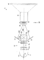
本実施形態に係るプロジェクタ1は、図1に示すように、光源部10と、ダイクロイックプリズム(色分離手段)20と、マイクロレンズアレイ(光学素子)25と、液晶ライトバルブ(光変調装置)30と、投射レンズ(投射手段)35とを備えている。
[First Embodiment]
The projector according to the present embodiment is a single-plate projection type color liquid crystal projector having one transmission type liquid crystal light valve for different color lights of R (red), G (green), and B (blue). It is projected onto the screen.
In the present embodiment, in the spatial separation method of illuminating the pixels of the transmissive liquid crystal panel corresponding to R, G, and B, the illumination Fno. In the second direction of illumination Fno. It becomes the composition which brightens.
As shown in FIG. 1, the projector 1 according to the present embodiment includes a
光源部10は、光源11と、シリンドリカルレンズ12と、第1,第2フライアレイレンズ13a,13bと、偏光変換素子14と、重畳レンズ15とを備えている。また、光源11は、赤色光(以下、「R光」という。)と緑色光(以下、「G光」という。)と青色光(以下、「B光」という。)とを含む白色光を射出するものである。
第1,第2フライアレイレンズ13a,13bは、高圧水銀ランプ11aから射出された光の照度分布を均一化するレンズである。
偏光変換素子14は、均一化された不定偏光状態の光を特定の偏光方向の光に変換する素子である。
The
The first and second
The
光源11は、光を射出する高圧水銀ランプ11aと、高圧水銀ランプ11aから射出された光を反射させるリフレクタ(反射部)11bとを備えている。リフレクタ11bは、縦方向(第一の方向、液晶ライトバルブ30の垂直方向:図1に示すX方向)と、横方向(第二の方向、液晶ライトバルブ30の水平方向:図1に示すY方向)との形状(曲率)が異なるアナモルフィックリフレクタである。
本実施形態のリフレクタ11bは、縦方向と横方向との曲率が異なり、リフレクタ11bから射出される光束の縦方向が細くなり、横方向が太くなるように形成されている。
シリンドリカルレンズ(集光手段)12は、縦方向と横方向との曲率が異なる凹状のレンズであり、縦方向の面における焦点距離が長く、横方向の面における焦点距離が短い。これにより、シリンドリカルレンズ12は、リフレクタ11bから射出された縦方向の光束が細く、横方向の光束が太い光を平行光として射出する。
The
The
The cylindrical lens (condensing means) 12 is a concave lens having different curvatures in the vertical direction and the horizontal direction, and has a long focal length on the vertical surface and a short focal length on the horizontal surface. As a result, the
ダイクロイックプリズム20は、重畳レンズ15により重畳された光をR光,G光,B光に分離するプリズムである。具体的には、ダイクロイックプリズム20は、互いに略直交するように配置された2つのダイクロイック膜20a,20bを有している。第1ダイクロイック膜20aは、R光を反射し、G光およびB光を透過させる特性を有している。一方、第2ダイクロイック膜20bは、B光を反射し、R光およびG光を透過させる特性を有している。これにより、ダイクロイックプリズム20の第1ダイクロイック膜20aにおいて反射し、光軸Oに対して90度曲げられたR光は、反射ミラー21により光軸Oに向かって反射される。また、ダイクロイックプリズム20の第2ダイクロイック膜20bにおいて反射し、光軸Oに対して90度曲げられたB光は、反射ミラー22により光軸Oに向かって反射される。すなわち、反射ミラー21において反射したR光及び反射ミラー22において反射したB光は液晶ライトバルブ30に向かって反射される。
The
次に、マイクロレンズアレイ25について、図2を参照して説明する。なお、図2はマイクロレンズアレイ25の一部を取り出して示した斜視図である。
マイクロレンズアレイ25は、図2に示すように、縦方向に複数アレイ状に配列されるとともに、入射した光を縦方向に集光させる第1シリンドリカルレンズ27と、横方向に複数アレイ状に配列されるとともに、入射した光を横方向に集光させる第2シリンドリカルレンズ28とを備えている。また、第1シリンドリカルレンズ27の縦方向の径がL1であり、第2シリンドリカルレンズ28の横方向の径がL2である。
また、第1シリンドリカルレンズ27と第2シリンドリカルレンズ28との間は、例えば、樹脂からなる接着部材26aが設けられている。そして、この接着部材26aにより、第1シリンドリカルレンズ27と第2シリンドリカルレンズ28との固定が行われる。また、第2シリンドリカルレンズ28の液晶ライトバルブ30側の面にも、例えば、樹脂からなる接着部材26bが設けられており、この接着部材26bにより、マイクロレンズアレイ25の射出端面25bを平坦面にしている。
この接着部材26a,26bの屈折率は、第1,第2シリンドリカルレンズ27,28を構成する材料の屈折率との差が大きい方が好ましい。
Next, the
As shown in FIG. 2, the
Further, an
It is preferable that the refractive index of the
次に、液晶ライトバルブ30の構成と、マイクロレンズアレイ25と液晶ライトバルブ30との位置関係について図3を参照して説明する。
なお、図3では、実際にはダイクロイックプリズム20から射出され広がった光をマイクロレンズアレイ25により集光させているが、図が煩雑になるのを避けるために、マイクロレンズアレイ25の中心を通過する光の主光軸のみを示す。さらに、図3では、実際には液晶ライトバルブ30はマトリクス状に複数のサブ画素31が配列されているが、X方向に1列のみ示す。
Next, the configuration of the liquid crystal
In FIG. 3, the light emitted from the
液晶ライトバルブ30は、高温ポリシリコンTFTを用いた透過型の液晶パネルである。また、液晶ライトバルブ30は、互いに異なる波長選択性を有し、ダイクロイックプリズム20において色分離されたR光,G光,B光を独立して変調可能な複数種類のサブ画素31をアレイ状に有している。具体的には、液晶ライトバルブ30は、R光が入射する赤色光用の複数のサブ画素30Rと、G光が入射する緑色光用の複数のサブ画素30Gと、B光が入射する青色光用の複数のサブ画素30Bとを有している。なお、サブ画素31とは、1画素を構成する最小単位であって、隣接配置された複数のサブ画素31(本実施形態では3つのサブ画素31)で1画素32が構成されている。
また、ブラックマトリックス(BM)30bのそれぞれの開口部30cが各サブ画素31の光透過領域となる。
The liquid crystal
Further, each opening 30 c of the black matrix (BM) 30 b becomes a light transmission region of each sub-pixel 31.
また、第1シリンドリカルレンズ27の縦方向の径L1が、液晶ライトバルブ30の縦方向の3サブ画素30R,30G,30B分(1画素32)のピッチP1と略同じである。また、第2シリンドリカルレンズ28の横方向の径L2が、液晶ライトバルブ30の横方向の1サブ画素30R,30G,30BのピッチP2と略同じである。
すなわち、図3に示すように、1つの第1シリンドリカルレンズ27に、液晶ライトバルブ30の縦方向の3つのサブ画素31が対応し、1つの第2シリンドリカルレンズ28に、液晶ライトバルブ30の横方向の1つのサブ画素31が対応している。
The vertical diameter L1 of the first
That is, as shown in FIG. 3, one
また、マイクロレンズアレイ25は、ダイクロイックプリズム20を透過したG光の光路上に配置されているため、図3に示すように、R光,B光は、G光に対しては対称にマイクロレンズアレイ25の入射端面25aに対して角度θをなして入射する。
これらにより、マイクロレンズアレイ25に入射したR光,G光は、第1シリンドリカルレンズ27により縦方向に射出方向が異なるように色分離され、各サブ画素30R,30G,30Bの開口部30cから入射する。
また、第1シリンドリカルレンズ27から射出され第2シリンドリカルレンズ28に入射したR光,G光,B光は、第2シリンドリカルレンズ28により横方向に集光され、各サブ画素30R,30G,30Bに効率良く入射する。
Further, since the
Accordingly, the R light and G light incident on the
In addition, the R light, G light, and B light emitted from the first
また、図1に示すように、ダイクロイックプリズム20とマイクロレンズアレイ25との間の光路上には、コンデンサーレンズ29が配置されている。このコンデンサーレンズ29により、テレセントリックな照明光となる。
また、投射レンズ35により、液晶ライトバルブ30において変調された光をスクリーン40に向かって拡大投射する。
As shown in FIG. 1, a condenser lens 29 is disposed on the optical path between the
The
本実施形態に係るプロジェクタ1では、縦方向に集光する第1シリンドリカルレンズ27と、横方向に集光する第2シリンドリカルレンズ28とを備えているため、縦方向と横方向との焦点距離を別々に設計することができる。すなわち、縦方向の照明Fno.を暗くしても、横方向の光がサブ画素31から外れないように、第2シリンドリカルレンズ28を第1シリンドリカルレンズ27に比べて焦点距離を短く設計することできる。これにより、開口部30c間のブラックマトリックス30b等によるケラレを押さえることが可能となるため、液晶ライトバルブ30の各サブ画素31に入射する光の照明効率の低下を抑えることが可能となる。
Since the projector 1 according to the present embodiment includes the first
さらには、ダイクロイックプリズム20により色分離された光を第1,第2シリンドリカルレンズ27,28により液晶ライトバルブ30の各サブ画素31に集光させているため、例えば、レンチキュラレンズに比べて焦点距離の短いレンズを作製し易い。したがって、液晶ライトバルブ30のサブ画素31のピッチP1が狭いときに、短い焦点距離を有する所望のレンズとして形成することができるため、微細なサブ画素31を有する液晶ライトバルブ30に対応可能となる。すなわち、サブ画素31のピッチP1に対応して第2シリンドリカルレンズ28の焦点距離を短くすることができるため、装置全体の小型化を図ることも可能となる。
Furthermore, since the light color-separated by the
また、縦方向の照明Fno.を暗くし、横方向の照明Fno.を明るくするため、縦方向に光を集光させる第1シリンドリカルレンズ27の焦点距離を長くし、横方向に光を集光させる第2シリンドリカルレンズ28の焦点距離を短くする。これにより、焦点距離が長い第1シリンドリカルレンズ27を光源11側に配置し、焦点距離が短い第2シリンドリカルレンズ28を液晶ライトバルブ30側に配置することにより、光源11から射出された光を第1,第2シリンドリカルレンズ27,28により効率良く集光させることができる。
Further, the vertical illumination Fno. Is darkened and the lateral illumination Fno. In order to brighten the light, the focal length of the first
また、液晶ライトバルブ30に入射するR光,G光,B光はテレセントリックな照明光となっているため、光変調手段として、特に、液晶ライトバルブ30を用いた場合に、液晶ライトバルブ30の入射端面30aに対して垂直に光を入射させることができる。これにより、液晶ライトバルブ30を通過する光のコントラストを向上させることができる。
Further, since the R light, G light, and B light incident on the liquid crystal
なお、第1シリンドリカルレンズ27と第2シリンドリカルレンズ28との間に、接着部材26a,26bを設けずに空気層であっても良い。
また、光源11のリフレクタ11bにより、縦方向の光束を細くし、横方向の光束を太くしたが、光源11から射出される光の形状はこれに限るものではない。
また、第1シリンドリカルレンズ27,第2シリンドリカルレンズ28の順に光源11側から配置したがこれに限るものではなく、第2シリンドリカルレンズ28,第1シリンドリカルレンズ27の順であっても良い。
さらに、図3では、マイクロレンズアレイ25と液晶ライトバルブ30とを間隔をあけて図示したが、極力近くに配置することが好ましく、接触していても良い。
また、光源11から射出された光をR光,G光,B光の3色に分けたが、これに限るものではなく、4色以上に分けても良い。この場合、第1シリンドリカルレンズ27の縦方向の径が、縦方向の1画素32のピッチと略等しくなるように形成すれば良い。
Note that an air layer may be provided without providing the
Further, although the light beam in the vertical direction is thinned and the light beam in the horizontal direction is thickened by the
Further, although the first
Further, in FIG. 3, the
Further, although the light emitted from the
[第1実施形態の変形例]
本変形例は、マイクロレンズアレイ25と液晶ライトバルブ30との間の光路上に、第1フィールドレンズ51及び第2フィールドレンズ52を有する光学素子50を備えている。このような変形例について、図4を参照して説明する。
なお、本実施形態においても、R,G,Bに対応して液晶ライトバルブ30のサブ画素30R,30G,30Bを照明する空間分離方式で、明るさを上げるために縦方向の照明Fno.を暗くし、横方向の照明Fno.を明るくする構成となっている。
また、図4では、実際にはダイクロイックプリズム20から射出され広がった光を光学素子50により集光させているが、図が煩雑になるのを避けるために、光学素子50の中心を通過する光の主光軸のみを示す。さらに、液晶ライトバルブ30はマトリクス状にサブ画素31が配列されているが、X方向に1列のみ示す。
[Modification of First Embodiment]
This modification includes an
In the present embodiment, the vertical illumination Fno. Is used to increase the brightness in the space separation system that illuminates the sub-pixels 30R, 30G, and 30B of the liquid crystal
In FIG. 4, the light emitted from the
第1フィールドレンズ51は、図4に示すように、第1シリンドリカルレンズ27と同様に、縦方向(X方向)に複数配列されており、第1シリンドリカルレンズ27から射出された光の主光軸を液晶ライトバルブ30の入射端面30aの縦方向に略垂直に入射させる。
また、第2フィールドレンズ52は、第2シリンドリカルレンズ28と同様に、横方向(Y方向)に複数配列されており、第2シリンドリカルレンズ28から射出された光の主光軸を液晶ライトバルブ30の入射端面30aの横方向に略垂直に入射させる。また、第1,第2フィールドレンズ51,52はシリンドリカルレンズである。
さらに、第1フィールドレンズ51が第2シリンドリカルレンズ28側に設けられており、第2フィールドレンズ52が液晶ライトバルブ30側に設けられている。
As shown in FIG. 4, the
Similarly to the second
Further, the
また、第2シリンドリカルレンズ28と第1フィールドレンズ51との間は、例えば、樹脂からなる接着部材56aが設けられており、この接着部材56aにより、第2シリンドリカルレンズ28と第1フィールドレンズ51との固定が行われる。また、第1フィールドレンズ51と第2フィールドレンズ52との間にも、例えば、樹脂からなる接着部材56bが設けられており、この接着部材56bにより、第1フィールドレンズ51と第2フィールドレンズ52との固定が行われる。さらに、第2フィールドレンズ52の液晶ライトバルブ30側の面にも、例えば、樹脂からなる接着部材56cが設けられており、この接着部材56cにより、光学素子50の射出端面50bを平坦面にしている。
この接着部材56a,56b,56cの屈折率は、第2シリンドリカルレンズ28,第1,第2フィールドレンズ51,52を構成する材料の屈折率との差が大きい方が好ましい。
Further, an
It is preferable that the refractive indexes of the
本変形例では、第1フィールドレンズ51及び第2フィールドレンズ52により、液晶ライトバルブ30に入射する光の入射角度が大きくなる。したがって、液晶ライトバルブ30の各サブ画素31を明るい照明光で照射することが可能となる。
また、第1フィールドレンズ51及び第2フィールドレンズ52により、液晶ライトバルブ30に垂直に光を入射させることで、液晶ライトバルブ30を通過する光のコントラストを向上させることができるため、鮮明な画像をスクリーン40に投射することが可能となる。
In this modification, the
In addition, since the
また、縦方向の照明Fno.を暗くし、横方向の照明Fno.を明るくするため、縦方向に光を集光させる第1フィールドレンズ51の焦点距離を長くし、横方向に光を集光させる第2フィールドレンズ52の焦点距離を短くする。これにより、焦点距離が長い第1フィールドレンズ51を光源11側の第2シリンドリカルレンズ28側に配置し、焦点距離が短い第2フィールドレンズ52を液晶ライトバルブ30側に配置することにより、光源11から射出された光を第1,第2フィールドレンズ51,52により液晶ライトバルブ30に効率良く集光させることができる。
なお、本変形例において、縦方向と横方向とで別々の第1フィールドレンズ51及び第2フィールドレンズ52を設けたが、縦方向及び横方向にフィールドレンズ機能を有するレンズを1つ設けた構成であっても良い。
Further, the vertical illumination Fno. Is darkened and the lateral illumination Fno. Is made longer, the focal length of the
In this modification, the
なお、本発明の技術範囲は上記実施形態に限定されるものではなく、本発明の趣旨を逸脱しない範囲において種々の変更を加えることが可能である。
例えば、色分離方法として、ダイクロイックプリズムを用いたが、3つのダイクロイックミラーの角度を変えて設けることにより、入射した光を分離しても良い。
The technical scope of the present invention is not limited to the above embodiment, and various modifications can be made without departing from the spirit of the present invention.
For example, although a dichroic prism is used as a color separation method, incident light may be separated by changing the angles of three dichroic mirrors.
L1,L2…径、P1,P2…ピッチ、1…プロジェクタ、11…光源、11b…リフレクタ(反射部)、12…シリンドリカルレンズ、20…ダイクロイックプリズム(色分離部)、25…マイクロレンズアレイ、27…第1シリンドリカルレンズ、28…第2シリンドリカルレンズ、30…液晶ライトバルブ(光変調手段)、30a…入射端面、35…投射レンズ(投射手段)、50…光学素子、51…第1フィールドレンズ、52…第2フィールドレンズ、 L1, L2 ... Diameter, P1, P2 ... Pitch, 1 ... Projector, 11 ... Light source, 11b ... Reflector (reflecting part), 12 ... Cylindrical lens, 20 ... Dichroic prism (color separation part), 25 ... Micro lens array, 27 DESCRIPTION OF SYMBOLS 1st cylindrical lens, 28 ... 2nd cylindrical lens, 30 ... Liquid crystal light valve (light modulation means), 30a ... Incident end face, 35 ... Projection lens (projection means), 50 ... Optical element, 51 ... 1st field lens, 52. Second field lens,
Claims (7)
該光源から射出された光を異なる色光ごとに射出方向が異なるように分離する色分離手段と、
複数種の色光に対応した複数のサブ画素で構成された1つの画素がアレイ状に配列され、入射した色光ごとに独立して変調可能な光変調手段と、
前記色分離手段と前記光変調手段との間の光路上に配置され、入射した光を色光ごとに複数種の前記サブ画素が配列された第一の方向に集光して異なる色光に対応した前記サブ画素に入射させる第1シリンドリカルレンズと、入射した光を前記第一の方向に略直交する第二の方向に集光して前記サブ画素に入射させる第2シリンドリカルレンズとがそれぞれアレイ状に配列されてなるマイクロレンズアレイと、
前記光変調手段により変調された光を投射する投射手段とを備え、
前記第1シリンドリカルレンズの第一の方向の径は、前記画素の前記第一の方向のピッチと略等しく、
前記第2シリンドリカルレンズの第二の方向の径は、前記サブ画素の前記第二の方向のピッチと略等しいことを特徴とするプロジェクタ。 A light source that emits light including multiple types of color light;
Color separation means for separating the light emitted from the light source so that the emission direction differs for each different color light;
A light modulation means in which one pixel composed of a plurality of sub-pixels corresponding to a plurality of types of color light is arranged in an array and can be modulated independently for each incident color light;
It is arranged on the optical path between the color separation unit and the light modulation unit, and incident light is condensed in a first direction in which a plurality of types of the sub-pixels are arranged for each color light to correspond to different color lights. A first cylindrical lens that is incident on the sub-pixel and a second cylindrical lens that collects incident light in a second direction substantially orthogonal to the first direction and is incident on the sub-pixel are arrayed, respectively. An array of microlens arrays;
Projecting means for projecting light modulated by the light modulating means,
The diameter of the first cylindrical lens in the first direction is substantially equal to the pitch of the pixels in the first direction;
The diameter of the second cylindrical lens in the second direction is approximately equal to the pitch of the sub-pixels in the second direction.
前記光源と前記色分離手段との間の光路上に配置され、前記第一の方向と前記第二の方向との曲率が異なるレンズ面を有し、前記反射部において反射した光を集光する集光手段とを備えることを特徴とする請求項1に記載のプロジェクタ。 The first direction and the second direction have different curvatures, and a reflection unit that reflects the light emitted from the light source;
A lens surface disposed on an optical path between the light source and the color separation unit, having a different curvature in the first direction and the second direction, collects the light reflected by the reflection unit. The projector according to claim 1, further comprising a light collecting unit.
前記第2シリンドリカルレンズから射出された光の主光軸を前記光変調手段の入射端面に対して略垂直とする第2フィールドレンズとを備え、
前記第1フィールドレンズ及び前記第2フィールドレンズはシリンドリカルレンズであることを特徴とする請求項1から請求項3のいずれか1項に記載のプロジェクタ。 A first field lens that makes a main optical axis of light emitted from the first cylindrical lens substantially perpendicular to an incident end face of the light modulation unit;
A second field lens that makes the main optical axis of the light emitted from the second cylindrical lens substantially perpendicular to the incident end face of the light modulator;
The projector according to any one of claims 1 to 3, wherein the first field lens and the second field lens are cylindrical lenses.
入射した光を色光ごとに複数種の前記サブ画素が配列された第一の方向に集光して異なる色光に対応した前記サブ画素に入射させる第1シリンドリカルレンズと、入射した光を前記第一の方向に略直交する第二の方向に集光して前記サブ画素に入射させる第2シリンドリカルレンズとがそれぞれアレイ状に配列されてなるマイクロレンズアレイと、
前記第1シリンドリカルレンズから射出された光の主光軸を前記光変調手段の入射端面に対して略垂直とする第1フィールドレンズと、
前記第2シリンドリカルレンズから射出された光の主光軸を前記光変調手段の入射端面に対して略垂直とする第2フィールドレンズとを備え、
前記第1シリンドリカルレンズの第一の方向の径は、前記画素の前記第一の方向のピッチと略等しく、
前記第2シリンドリカルレンズの第二の方向の径は、前記サブ画素の前記第二の方向のピッチと略等しいことを特徴とする光学素子。 An optical element that causes light to be incident on each sub-pixel of the light modulation unit in which one pixel composed of a plurality of sub-pixels is arranged in an array,
A first cylindrical lens that condenses incident light in a first direction in which a plurality of types of sub-pixels are arranged for each color light and enters the sub-pixels corresponding to different color lights; and A microlens array in which second cylindrical lenses that are condensed in a second direction substantially orthogonal to the direction of the light and incident on the sub-pixels are arranged in an array,
A first field lens that makes a main optical axis of light emitted from the first cylindrical lens substantially perpendicular to an incident end face of the light modulation unit;
A second field lens that makes the main optical axis of the light emitted from the second cylindrical lens substantially perpendicular to the incident end face of the light modulator;
The diameter of the first cylindrical lens in the first direction is substantially equal to the pitch of the pixels in the first direction;
The diameter of the second cylindrical lens in the second direction is substantially equal to the pitch of the sub-pixels in the second direction.
請求項6に記載の光学素子とを備えることを特徴とする光変調装置。 A light modulation means in which one pixel composed of a plurality of sub-pixels is arranged in an array and can be modulated independently for each incident color light;
An optical modulation device comprising the optical element according to claim 6.
Priority Applications (1)
| Application Number | Priority Date | Filing Date | Title |
|---|---|---|---|
| JP2007232829A JP2009063892A (en) | 2007-09-07 | 2007-09-07 | Projector, optical element, and optical modulating device |
Applications Claiming Priority (1)
| Application Number | Priority Date | Filing Date | Title |
|---|---|---|---|
| JP2007232829A JP2009063892A (en) | 2007-09-07 | 2007-09-07 | Projector, optical element, and optical modulating device |
Publications (1)
| Publication Number | Publication Date |
|---|---|
| JP2009063892A true JP2009063892A (en) | 2009-03-26 |
Family
ID=40558506
Family Applications (1)
| Application Number | Title | Priority Date | Filing Date |
|---|---|---|---|
| JP2007232829A Pending JP2009063892A (en) | 2007-09-07 | 2007-09-07 | Projector, optical element, and optical modulating device |
Country Status (1)
| Country | Link |
|---|---|
| JP (1) | JP2009063892A (en) |
Cited By (6)
| Publication number | Priority date | Publication date | Assignee | Title |
|---|---|---|---|---|
| US8714747B2 (en) | 2011-07-27 | 2014-05-06 | Seiko Epson Corporation | Projector having a first light separation optical system and a second light separation optical system |
| JP2018132772A (en) * | 2016-02-23 | 2018-08-23 | 株式会社デンソー | Head-up display device |
| CN110998416A (en) * | 2017-08-09 | 2020-04-10 | 株式会社电装 | Stereoscopic display device |
| US10928718B2 (en) | 2019-02-05 | 2021-02-23 | Seiko Epson Corporation | Projector |
| US11412193B2 (en) | 2019-02-01 | 2022-08-09 | Seiko Epson Corporation | Projector |
| JP7463925B2 (en) | 2020-09-16 | 2024-04-09 | セイコーエプソン株式会社 | Light source device and projector |
-
2007
- 2007-09-07 JP JP2007232829A patent/JP2009063892A/en active Pending
Cited By (6)
| Publication number | Priority date | Publication date | Assignee | Title |
|---|---|---|---|---|
| US8714747B2 (en) | 2011-07-27 | 2014-05-06 | Seiko Epson Corporation | Projector having a first light separation optical system and a second light separation optical system |
| JP2018132772A (en) * | 2016-02-23 | 2018-08-23 | 株式会社デンソー | Head-up display device |
| CN110998416A (en) * | 2017-08-09 | 2020-04-10 | 株式会社电装 | Stereoscopic display device |
| US11412193B2 (en) | 2019-02-01 | 2022-08-09 | Seiko Epson Corporation | Projector |
| US10928718B2 (en) | 2019-02-05 | 2021-02-23 | Seiko Epson Corporation | Projector |
| JP7463925B2 (en) | 2020-09-16 | 2024-04-09 | セイコーエプソン株式会社 | Light source device and projector |
Similar Documents
| Publication | Publication Date | Title |
|---|---|---|
| US20060082692A1 (en) | Image display device and projector | |
| JP3953979B2 (en) | Illumination optical system using dichroic mirror wheel and image display apparatus having the same | |
| JP5494678B2 (en) | Illumination optical system and projector apparatus | |
| JP2000098296A (en) | Projection type color picture display device | |
| US6680762B2 (en) | Projection liquid crystal display apparatus wherein overall focal point of the lens is shifted to increase effective aperture ratio | |
| JP3473075B2 (en) | Lighting device and projection display device | |
| JP5807430B2 (en) | projector | |
| JP2009063892A (en) | Projector, optical element, and optical modulating device | |
| JP2011022311A (en) | Liquid crystal panel and projection type display device using the same | |
| JP2000241768A (en) | Illumination optical device | |
| US7401930B2 (en) | Projection system | |
| US8398244B2 (en) | Projector | |
| JP4200772B2 (en) | Lighting device and projector | |
| US10481473B2 (en) | Image projection apparatus | |
| JP5707984B2 (en) | projector | |
| JP2008165136A (en) | Projector | |
| JPWO2005019929A1 (en) | projector | |
| JP2007328218A (en) | Display device | |
| JP2000305171A (en) | Illumination device and projection type display device | |
| JP2009063893A (en) | Projector, optical element, and optical modulating device | |
| JP4893780B2 (en) | LIGHTING DEVICE AND PROJECTOR HAVING THE SAME | |
| JP3610804B2 (en) | Illumination device and projection display device | |
| JP3528850B2 (en) | Projection display device | |
| JP4971774B2 (en) | Illumination device and projection display device | |
| JP4696503B2 (en) | Image display device |