EP3620297A1 - Panneau insonorisant avec une ame alveolaire et un systeme de degivrage - Google Patents
Panneau insonorisant avec une ame alveolaire et un systeme de degivrage Download PDFInfo
- Publication number
- EP3620297A1 EP3620297A1 EP19185659.0A EP19185659A EP3620297A1 EP 3620297 A1 EP3620297 A1 EP 3620297A1 EP 19185659 A EP19185659 A EP 19185659A EP 3620297 A1 EP3620297 A1 EP 3620297A1
- Authority
- EP
- European Patent Office
- Prior art keywords
- sole
- bars
- panel
- soundproofing panel
- fixed
- Prior art date
- Legal status (The legal status is an assumption and is not a legal conclusion. Google has not performed a legal analysis and makes no representation as to the accuracy of the status listed.)
- Granted
Links
Images

Classifications
-
- B—PERFORMING OPERATIONS; TRANSPORTING
- B32—LAYERED PRODUCTS
- B32B—LAYERED PRODUCTS, i.e. PRODUCTS BUILT-UP OF STRATA OF FLAT OR NON-FLAT, e.g. CELLULAR OR HONEYCOMB, FORM
- B32B1/00—Layered products having a non-planar shape
-
- B—PERFORMING OPERATIONS; TRANSPORTING
- B64—AIRCRAFT; AVIATION; COSMONAUTICS
- B64C—AEROPLANES; HELICOPTERS
- B64C1/00—Fuselages; Constructional features common to fuselages, wings, stabilising surfaces or the like
- B64C1/40—Sound or heat insulation, e.g. using insulation blankets
-
- B—PERFORMING OPERATIONS; TRANSPORTING
- B32—LAYERED PRODUCTS
- B32B—LAYERED PRODUCTS, i.e. PRODUCTS BUILT-UP OF STRATA OF FLAT OR NON-FLAT, e.g. CELLULAR OR HONEYCOMB, FORM
- B32B3/00—Layered products comprising a layer with external or internal discontinuities or unevennesses, or a layer of non-planar shape; Layered products comprising a layer having particular features of form
- B32B3/02—Layered products comprising a layer with external or internal discontinuities or unevennesses, or a layer of non-planar shape; Layered products comprising a layer having particular features of form characterised by features of form at particular places, e.g. in edge regions
- B32B3/08—Layered products comprising a layer with external or internal discontinuities or unevennesses, or a layer of non-planar shape; Layered products comprising a layer having particular features of form characterised by features of form at particular places, e.g. in edge regions characterised by added members at particular parts
-
- B—PERFORMING OPERATIONS; TRANSPORTING
- B32—LAYERED PRODUCTS
- B32B—LAYERED PRODUCTS, i.e. PRODUCTS BUILT-UP OF STRATA OF FLAT OR NON-FLAT, e.g. CELLULAR OR HONEYCOMB, FORM
- B32B3/00—Layered products comprising a layer with external or internal discontinuities or unevennesses, or a layer of non-planar shape; Layered products comprising a layer having particular features of form
- B32B3/10—Layered products comprising a layer with external or internal discontinuities or unevennesses, or a layer of non-planar shape; Layered products comprising a layer having particular features of form characterised by a discontinuous layer, i.e. formed of separate pieces of material
- B32B3/12—Layered products comprising a layer with external or internal discontinuities or unevennesses, or a layer of non-planar shape; Layered products comprising a layer having particular features of form characterised by a discontinuous layer, i.e. formed of separate pieces of material characterised by a layer of regularly- arranged cells, e.g. a honeycomb structure
-
- B—PERFORMING OPERATIONS; TRANSPORTING
- B32—LAYERED PRODUCTS
- B32B—LAYERED PRODUCTS, i.e. PRODUCTS BUILT-UP OF STRATA OF FLAT OR NON-FLAT, e.g. CELLULAR OR HONEYCOMB, FORM
- B32B3/00—Layered products comprising a layer with external or internal discontinuities or unevennesses, or a layer of non-planar shape; Layered products comprising a layer having particular features of form
- B32B3/26—Layered products comprising a layer with external or internal discontinuities or unevennesses, or a layer of non-planar shape; Layered products comprising a layer having particular features of form characterised by a particular shape of the outline of the cross-section of a continuous layer; characterised by a layer with cavities or internal voids ; characterised by an apertured layer
- B32B3/266—Layered products comprising a layer with external or internal discontinuities or unevennesses, or a layer of non-planar shape; Layered products comprising a layer having particular features of form characterised by a particular shape of the outline of the cross-section of a continuous layer; characterised by a layer with cavities or internal voids ; characterised by an apertured layer characterised by an apertured layer, the apertures going through the whole thickness of the layer, e.g. expanded metal, perforated layer, slit layer regular cells B32B3/12
-
- B—PERFORMING OPERATIONS; TRANSPORTING
- B32—LAYERED PRODUCTS
- B32B—LAYERED PRODUCTS, i.e. PRODUCTS BUILT-UP OF STRATA OF FLAT OR NON-FLAT, e.g. CELLULAR OR HONEYCOMB, FORM
- B32B3/00—Layered products comprising a layer with external or internal discontinuities or unevennesses, or a layer of non-planar shape; Layered products comprising a layer having particular features of form
- B32B3/26—Layered products comprising a layer with external or internal discontinuities or unevennesses, or a layer of non-planar shape; Layered products comprising a layer having particular features of form characterised by a particular shape of the outline of the cross-section of a continuous layer; characterised by a layer with cavities or internal voids ; characterised by an apertured layer
- B32B3/30—Layered products comprising a layer with external or internal discontinuities or unevennesses, or a layer of non-planar shape; Layered products comprising a layer having particular features of form characterised by a particular shape of the outline of the cross-section of a continuous layer; characterised by a layer with cavities or internal voids ; characterised by an apertured layer characterised by a layer formed with recesses or projections, e.g. hollows, grooves, protuberances, ribs
-
- B—PERFORMING OPERATIONS; TRANSPORTING
- B32—LAYERED PRODUCTS
- B32B—LAYERED PRODUCTS, i.e. PRODUCTS BUILT-UP OF STRATA OF FLAT OR NON-FLAT, e.g. CELLULAR OR HONEYCOMB, FORM
- B32B5/00—Layered products characterised by the non- homogeneity or physical structure, i.e. comprising a fibrous, filamentary, particulate or foam layer; Layered products characterised by having a layer differing constitutionally or physically in different parts
- B32B5/02—Layered products characterised by the non- homogeneity or physical structure, i.e. comprising a fibrous, filamentary, particulate or foam layer; Layered products characterised by having a layer differing constitutionally or physically in different parts characterised by structural features of a fibrous or filamentary layer
-
- B—PERFORMING OPERATIONS; TRANSPORTING
- B32—LAYERED PRODUCTS
- B32B—LAYERED PRODUCTS, i.e. PRODUCTS BUILT-UP OF STRATA OF FLAT OR NON-FLAT, e.g. CELLULAR OR HONEYCOMB, FORM
- B32B5/00—Layered products characterised by the non- homogeneity or physical structure, i.e. comprising a fibrous, filamentary, particulate or foam layer; Layered products characterised by having a layer differing constitutionally or physically in different parts
- B32B5/02—Layered products characterised by the non- homogeneity or physical structure, i.e. comprising a fibrous, filamentary, particulate or foam layer; Layered products characterised by having a layer differing constitutionally or physically in different parts characterised by structural features of a fibrous or filamentary layer
- B32B5/028—Net structure, e.g. spaced apart filaments bonded at the crossing points
-
- B—PERFORMING OPERATIONS; TRANSPORTING
- B64—AIRCRAFT; AVIATION; COSMONAUTICS
- B64D—EQUIPMENT FOR FITTING IN OR TO AIRCRAFT; FLIGHT SUITS; PARACHUTES; ARRANGEMENT OR MOUNTING OF POWER PLANTS OR PROPULSION TRANSMISSIONS IN AIRCRAFT
- B64D15/00—De-icing or preventing icing on exterior surfaces of aircraft
- B64D15/12—De-icing or preventing icing on exterior surfaces of aircraft by electric heating
-
- B—PERFORMING OPERATIONS; TRANSPORTING
- B64—AIRCRAFT; AVIATION; COSMONAUTICS
- B64D—EQUIPMENT FOR FITTING IN OR TO AIRCRAFT; FLIGHT SUITS; PARACHUTES; ARRANGEMENT OR MOUNTING OF POWER PLANTS OR PROPULSION TRANSMISSIONS IN AIRCRAFT
- B64D29/00—Power-plant nacelles, fairings or cowlings
-
- B—PERFORMING OPERATIONS; TRANSPORTING
- B64—AIRCRAFT; AVIATION; COSMONAUTICS
- B64D—EQUIPMENT FOR FITTING IN OR TO AIRCRAFT; FLIGHT SUITS; PARACHUTES; ARRANGEMENT OR MOUNTING OF POWER PLANTS OR PROPULSION TRANSMISSIONS IN AIRCRAFT
- B64D33/00—Arrangement in aircraft of power plant parts or auxiliaries not otherwise provided for
-
- B—PERFORMING OPERATIONS; TRANSPORTING
- B64—AIRCRAFT; AVIATION; COSMONAUTICS
- B64D—EQUIPMENT FOR FITTING IN OR TO AIRCRAFT; FLIGHT SUITS; PARACHUTES; ARRANGEMENT OR MOUNTING OF POWER PLANTS OR PROPULSION TRANSMISSIONS IN AIRCRAFT
- B64D33/00—Arrangement in aircraft of power plant parts or auxiliaries not otherwise provided for
- B64D33/02—Arrangement in aircraft of power plant parts or auxiliaries not otherwise provided for of combustion air intakes
-
- F—MECHANICAL ENGINEERING; LIGHTING; HEATING; WEAPONS; BLASTING
- F02—COMBUSTION ENGINES; HOT-GAS OR COMBUSTION-PRODUCT ENGINE PLANTS
- F02C—GAS-TURBINE PLANTS; AIR INTAKES FOR JET-PROPULSION PLANTS; CONTROLLING FUEL SUPPLY IN AIR-BREATHING JET-PROPULSION PLANTS
- F02C7/00—Features, components parts, details or accessories, not provided for in, or of interest apart form groups F02C1/00 - F02C6/00; Air intakes for jet-propulsion plants
- F02C7/04—Air intakes for gas-turbine plants or jet-propulsion plants
- F02C7/047—Heating to prevent icing
-
- G—PHYSICS
- G10—MUSICAL INSTRUMENTS; ACOUSTICS
- G10K—SOUND-PRODUCING DEVICES; METHODS OR DEVICES FOR PROTECTING AGAINST, OR FOR DAMPING, NOISE OR OTHER ACOUSTIC WAVES IN GENERAL; ACOUSTICS NOT OTHERWISE PROVIDED FOR
- G10K11/00—Methods or devices for transmitting, conducting or directing sound in general; Methods or devices for protecting against, or for damping, noise or other acoustic waves in general
- G10K11/16—Methods or devices for protecting against, or for damping, noise or other acoustic waves in general
- G10K11/162—Selection of materials
- G10K11/168—Plural layers of different materials, e.g. sandwiches
-
- B—PERFORMING OPERATIONS; TRANSPORTING
- B32—LAYERED PRODUCTS
- B32B—LAYERED PRODUCTS, i.e. PRODUCTS BUILT-UP OF STRATA OF FLAT OR NON-FLAT, e.g. CELLULAR OR HONEYCOMB, FORM
- B32B2250/00—Layers arrangement
- B32B2250/04—4 layers
-
- B—PERFORMING OPERATIONS; TRANSPORTING
- B32—LAYERED PRODUCTS
- B32B—LAYERED PRODUCTS, i.e. PRODUCTS BUILT-UP OF STRATA OF FLAT OR NON-FLAT, e.g. CELLULAR OR HONEYCOMB, FORM
- B32B2250/00—Layers arrangement
- B32B2250/05—5 or more layers
-
- B—PERFORMING OPERATIONS; TRANSPORTING
- B32—LAYERED PRODUCTS
- B32B—LAYERED PRODUCTS, i.e. PRODUCTS BUILT-UP OF STRATA OF FLAT OR NON-FLAT, e.g. CELLULAR OR HONEYCOMB, FORM
- B32B2307/00—Properties of the layers or laminate
- B32B2307/10—Properties of the layers or laminate having particular acoustical properties
- B32B2307/102—Insulating
-
- B—PERFORMING OPERATIONS; TRANSPORTING
- B32—LAYERED PRODUCTS
- B32B—LAYERED PRODUCTS, i.e. PRODUCTS BUILT-UP OF STRATA OF FLAT OR NON-FLAT, e.g. CELLULAR OR HONEYCOMB, FORM
- B32B2307/00—Properties of the layers or laminate
- B32B2307/20—Properties of the layers or laminate having particular electrical or magnetic properties, e.g. piezoelectric
- B32B2307/202—Conductive
-
- B—PERFORMING OPERATIONS; TRANSPORTING
- B32—LAYERED PRODUCTS
- B32B—LAYERED PRODUCTS, i.e. PRODUCTS BUILT-UP OF STRATA OF FLAT OR NON-FLAT, e.g. CELLULAR OR HONEYCOMB, FORM
- B32B2307/00—Properties of the layers or laminate
- B32B2307/20—Properties of the layers or laminate having particular electrical or magnetic properties, e.g. piezoelectric
- B32B2307/206—Insulating
-
- B—PERFORMING OPERATIONS; TRANSPORTING
- B32—LAYERED PRODUCTS
- B32B—LAYERED PRODUCTS, i.e. PRODUCTS BUILT-UP OF STRATA OF FLAT OR NON-FLAT, e.g. CELLULAR OR HONEYCOMB, FORM
- B32B2307/00—Properties of the layers or laminate
- B32B2307/30—Properties of the layers or laminate having particular thermal properties
- B32B2307/302—Conductive
-
- B—PERFORMING OPERATIONS; TRANSPORTING
- B32—LAYERED PRODUCTS
- B32B—LAYERED PRODUCTS, i.e. PRODUCTS BUILT-UP OF STRATA OF FLAT OR NON-FLAT, e.g. CELLULAR OR HONEYCOMB, FORM
- B32B2307/00—Properties of the layers or laminate
- B32B2307/70—Other properties
- B32B2307/732—Dimensional properties
-
- B—PERFORMING OPERATIONS; TRANSPORTING
- B32—LAYERED PRODUCTS
- B32B—LAYERED PRODUCTS, i.e. PRODUCTS BUILT-UP OF STRATA OF FLAT OR NON-FLAT, e.g. CELLULAR OR HONEYCOMB, FORM
- B32B2603/00—Vanes, blades, propellers, rotors with blades
-
- B—PERFORMING OPERATIONS; TRANSPORTING
- B32—LAYERED PRODUCTS
- B32B—LAYERED PRODUCTS, i.e. PRODUCTS BUILT-UP OF STRATA OF FLAT OR NON-FLAT, e.g. CELLULAR OR HONEYCOMB, FORM
- B32B2605/00—Vehicles
- B32B2605/18—Aircraft
-
- B—PERFORMING OPERATIONS; TRANSPORTING
- B64—AIRCRAFT; AVIATION; COSMONAUTICS
- B64D—EQUIPMENT FOR FITTING IN OR TO AIRCRAFT; FLIGHT SUITS; PARACHUTES; ARRANGEMENT OR MOUNTING OF POWER PLANTS OR PROPULSION TRANSMISSIONS IN AIRCRAFT
- B64D33/00—Arrangement in aircraft of power plant parts or auxiliaries not otherwise provided for
- B64D33/02—Arrangement in aircraft of power plant parts or auxiliaries not otherwise provided for of combustion air intakes
- B64D2033/0206—Arrangement in aircraft of power plant parts or auxiliaries not otherwise provided for of combustion air intakes comprising noise reduction means, e.g. acoustic liners
-
- B—PERFORMING OPERATIONS; TRANSPORTING
- B64—AIRCRAFT; AVIATION; COSMONAUTICS
- B64D—EQUIPMENT FOR FITTING IN OR TO AIRCRAFT; FLIGHT SUITS; PARACHUTES; ARRANGEMENT OR MOUNTING OF POWER PLANTS OR PROPULSION TRANSMISSIONS IN AIRCRAFT
- B64D33/00—Arrangement in aircraft of power plant parts or auxiliaries not otherwise provided for
- B64D33/02—Arrangement in aircraft of power plant parts or auxiliaries not otherwise provided for of combustion air intakes
- B64D2033/0233—Arrangement in aircraft of power plant parts or auxiliaries not otherwise provided for of combustion air intakes comprising de-icing means
-
- B—PERFORMING OPERATIONS; TRANSPORTING
- B64—AIRCRAFT; AVIATION; COSMONAUTICS
- B64D—EQUIPMENT FOR FITTING IN OR TO AIRCRAFT; FLIGHT SUITS; PARACHUTES; ARRANGEMENT OR MOUNTING OF POWER PLANTS OR PROPULSION TRANSMISSIONS IN AIRCRAFT
- B64D33/00—Arrangement in aircraft of power plant parts or auxiliaries not otherwise provided for
- B64D33/02—Arrangement in aircraft of power plant parts or auxiliaries not otherwise provided for of combustion air intakes
- B64D2033/0266—Arrangement in aircraft of power plant parts or auxiliaries not otherwise provided for of combustion air intakes specially adapted for particular type of power plants
- B64D2033/0286—Arrangement in aircraft of power plant parts or auxiliaries not otherwise provided for of combustion air intakes specially adapted for particular type of power plants for turbofan engines
-
- Y—GENERAL TAGGING OF NEW TECHNOLOGICAL DEVELOPMENTS; GENERAL TAGGING OF CROSS-SECTIONAL TECHNOLOGIES SPANNING OVER SEVERAL SECTIONS OF THE IPC; TECHNICAL SUBJECTS COVERED BY FORMER USPC CROSS-REFERENCE ART COLLECTIONS [XRACs] AND DIGESTS
- Y02—TECHNOLOGIES OR APPLICATIONS FOR MITIGATION OR ADAPTATION AGAINST CLIMATE CHANGE
- Y02T—CLIMATE CHANGE MITIGATION TECHNOLOGIES RELATED TO TRANSPORTATION
- Y02T50/00—Aeronautics or air transport
- Y02T50/60—Efficient propulsion technologies, e.g. for aircraft
Definitions
- the present invention relates to a soundproofing panel with a cellular core and a defrosting system, an air intake structure of an aircraft nacelle comprising such a soundproofing panel, a nacelle comprising such an air intake structure. and an aircraft comprising at least one such nacelle.
- Soundproofing panels are used in many technical fields, notably in the aeronautical field.
- An aircraft turbine engine comprises a nacelle in which the engine is housed.
- the nacelle which takes an annular shape has an air intake structure at the front.
- the air intake structure generally comprises an interior face and an exterior face in contact with the outside air, while the interior face delimits a vein which constitutes the fan channel.
- the function of the air intake structure is in particular to ensure the aerodynamic flow of air, on the one hand, towards the fan channel and, on the other hand, towards the outside of the nacelle.
- the air intake structure conventionally comprises an air intake lip, a front reinforcement frame and an acoustic panel.
- the air intake lip has the shape of a U open in rear section, it forms the outer envelope of the front part of the air intake structure and it ensures the sharing of air between the part which enters the blower channel and the part which flows around the nacelle.
- the front reinforcement frame also has the shape of a U open towards the rear in section and is placed inside and behind the air intake lip.
- the front reinforcement frame ensures the mechanical strength of the front part of the nacelle and helps to preserve its shape and sizing.
- the acoustic panel forms the interior envelope of the nacelle, behind the air intake lip, on the side of the blower channel.
- the acoustic panel therefore forms part of the interior face.
- the acoustic panel has a structure capable of attenuating the noises produced by the engine and in particular by the fan.
- This acoustic panel is of the sandwich composite type, and it incorporates a cellular core between an interior wall and an exterior wall.
- the inner wall defines the blower channel and extends the air intake lip, while the outer wall is inside the air intake structure but oriented towards the outside of the nacelle.
- the volume between the air intake lip and the front reinforcement frame allows the circulation of a hot air flow which defrosts the air intake lip.
- An object of the present invention is to provide a soundproofing panel which provides better attenuation of noise and defrosting.
- Such a soundproofing panel thus makes it possible to obtain a defrosted surface and better attenuation of noise.
- the bars are integral with each other.
- the first direction and the second direction are perpendicular.
- the total thickness of the sole at the ribs is at least 4 mm.
- each strip comprises an electrically resistive element which heats up when a current passes through it and an electrical insulator in which the resistive element is embedded.
- each bar is traversed by a tube in which a heated heat transfer fluid circulates.
- the inner skin is made of a thermal conductive material.
- the invention also proposes an air intake structure for a nacelle of an aircraft, said air intake structure defining a vein and comprising a lip having a U-shaped section oriented towards the rear and a first panel. soundproofing according to one of the preceding variants fixed to the rear of the lip and delimiting the vein.
- the air intake structure comprises a second soundproofing panel fixed to the rear of the first soundproofing panel and comprising a honeycomb core fixed between an inner skin pierced with holes and oriented towards the vein and an outer panel oriented towards the opposite.
- the invention also provides a nacelle comprising at the front, an air intake structure according to one of the preceding variants.
- the invention also provides an aircraft comprising at least one nacelle according to the previous variant.
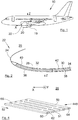
- the Fig. 1 shows an aircraft 10 which comprises at least one turbine engine 20.
- the direction X corresponds to the longitudinal direction of the turbine engine 20, this direction being parallel to the longitudinal axis X of the turbine engine 20.
- the direction Y corresponds to the oriented direction transversely with respect to the turbine engine 20, and the direction Z corresponds to the vertical direction or height, these three directions X, Y, Z being orthogonal to one another.
- the turbine engine 20 conventionally comprises a nacelle 19 which comprises at the front an air intake structure 22 comprising a lip which delimits the interior and the exterior of the nacelle 19.
- the lip is extended inward by a inner wall which extends around a vein which channels the air towards a motorization which comprises inter alia a blower.
- the Fig. 2 shows an air intake structure 22 which comprises a lip 24 which has a U-shaped section oriented towards the rear and which generally takes an annular shape.
- the air intake structure 22 defines a channel 26 which channels the air towards the motorization and in particular towards the blower.
- the lip 24 delimits the exterior 25 and the interior 26 of the nacelle 19.
- the interior 26 corresponds to the vein 26.
- the air intake structure 22 comprises around the vein 26 a first soundproofing panel 28 and a second soundproofing panel 30 which delimit the vein 26.
- the first soundproofing panel 28 is fixed at the rear of the lip 24 to the second sound absorbing panel 30.
- the second sound absorbing panel 30 is fixed at the rear of the first sound absorbing panel 28.
- the reinforcing frame has been eliminated and the air intake structure 22 of the invention is reinforced by the presence of the first soundproofing panel 28 which also has structural capacities.
- the second soundproofing panel 30 comprises a cellular core 34 which is fixed between an inner skin 38 oriented towards the vein 26 and an outer panel 42 oriented opposite.
- the inner skin 38 is pierced with holes allowing the sound waves to propagate in the core 34 to be attenuated there.
- the second soundproofing panel 30 is provided to attenuate the high frequencies which extend between 1000 and 4000 Hz.
- the inner skin 38 of the second soundproofing panel 30 has a thickness of the order of 0.9 to 2 mm and the holes 46 therefore also have a depth of at least 0.9 to 2 mm.
- the Fig. 3 shows an exploded view of the first soundproofing panel 28.
- the first soundproofing panel 28 has an inner skin 36 oriented towards the vein 26 and traversed with holes allowing the sound waves to propagate through the inner skin 36.
- the inner skin 36 is intended to be oriented towards a vein 26 in which a fluid flows.
- the inner skin 36 may for example be of the porous element type such as a porous fabric or a mesh.
- the first soundproofing panel 28 also includes a heating mattress 48 which consists of bars 50 which are fixed to the inner skin 36 on the side opposite to the vein 26. All the bars 50 are oriented in a first direction 52. Two neighboring bars 50 are distant from each other in order to leave a slot 51 between them. The holes in the inner skin 36 open into these slots 51 which allow the sound waves to progress.
- a heating mattress 48 which consists of bars 50 which are fixed to the inner skin 36 on the side opposite to the vein 26. All the bars 50 are oriented in a first direction 52. Two neighboring bars 50 are distant from each other in order to leave a slot 51 between them. The holes in the inner skin 36 open into these slots 51 which allow the sound waves to progress.
- the heating mattress 48 defrosts the face of the inner skin 36 which is in the vein 26.
- the first soundproofing panel 28 also includes a sole 53 which is fixed to the bars 50 on the side opposite to the inner skin 36.
- the sole 53 has, on the side of the bars 50, grooves 54 which extend in a second direction 56 different from the first direction 52 and more particularly perpendicular to the first direction 52.
- the sole 53 thus has between two successive grooves 54, a rib 58 parallel to the second direction 56. The sole 53 thus rests on the bars 50 by the ribs 58.
- the sole 53 is also crossed with holes which allow the progression of the sound waves.
- the total thickness of the sole 53 at the ribs 58 is of the order of 0.9 mm to 5 mm and the depths of the holes which pass through the ribs 58 are therefore also equal to 0.9 to 5 mm.
- the thickness of the sole 53 at the grooves 54 is for example of the order of 0.3 to 0.9 mm and the holes which pass through it therefore also have a depth of 0.3 to 0.9 mm.
- the total thickness of the sole 53 at the ribs 58 is at least 4 mm.
- the first soundproofing panel 28 also includes a cellular core 32 which is fixed to the sole 53 on the side opposite the bars 50.
- the first soundproofing panel 28 also includes an outer panel 40 which is fixed to the cellular core 32 on the side opposite to the sole 53.
- Such a structure allows better attenuation of noise because the sound waves will propagate through the inner skin 36, the slots 51, the grooves 54, the sole 53 and finally the cellular core 32.
- the succession of holes of small diameters and larger spaces creates variations which slow down the sound waves and therefore attenuate the noise.
- the sole 53 at the ribs 58 makes it possible to attenuate the low frequencies which extend between 300 and 600 Hz.
- the volumes of the alveoli of the alveolar core 32 into which open out the holes of the sole 53 and the depths of these holes make it possible to select the frequency to be attenuated. For example, for a hole depth of 4 mm and a cell height of 40 mm, the frequencies around 500 Hz are attenuated.
- the attenuation of sound waves is therefore extended compared to the prior art and the range of attenuated frequencies is also extended by the use of soundproofing panels based on two different technologies.
- the face of the inner skin 36 of the first soundproofing panel 28 which is oriented towards the vein 26 is flush with the face of the inner skin 38 of the second soundproofing panel 30 which is oriented towards the vein 26 in order to produce an aerodynamic surface.
- the inner skin 38 of the second soundproofing panel 30 also preferably includes a heat source which is embedded in the mass of said inner skin 38.
- Each bar 50 comprises for example an electrically resistive element 60 which heats up when a current flows through it and an electrical insulator 62 in which the resistive element 60 is embedded.
- Each bar 50 can be traversed by a tube 64 in which a heated heat transfer fluid circulates, for example hot air.
- the inner skin 36 is made of a thermal conductive material.
- thermal insulation on certain sides of the bars 50 in order to limit the propagation of heat in certain directions. It is also possible to have thermal conductors on certain sides of the bars 50 in order to promote the propagation of heat in certain directions.
- the Fig. 4 shows a heating mattress 448 according to a particular embodiment, in which, in order to facilitate the handling of the heating mattress 448, the bars 50 are secured to each other for example by bridges 66 which pass through the slots 61. The heating mattress 448 then becomes an openwork plate.
Landscapes
- Engineering & Computer Science (AREA)
- Aviation & Aerospace Engineering (AREA)
- Chemical & Material Sciences (AREA)
- Combustion & Propulsion (AREA)
- Mechanical Engineering (AREA)
- General Engineering & Computer Science (AREA)
- Physics & Mathematics (AREA)
- Acoustics & Sound (AREA)
- Multimedia (AREA)
- Soundproofing, Sound Blocking, And Sound Damping (AREA)
- Vehicle Interior And Exterior Ornaments, Soundproofing, And Insulation (AREA)
- Building Environments (AREA)
Abstract
Description
- La présente invention concerne un panneau insonorisant avec une âme alvéolaire et un système de dégivrage, une structure d'entrée d'air d'une nacelle d'aéronef comportant un tel panneau insonorisant, une nacelle comportant une telle structure d'entrée d'air et un aéronef comportant au moins une telle nacelle.
- Les panneaux insonorisants sont employés dans de nombreux domaines techniques, notamment dans le domaine aéronautique.
- Un turbomoteur d'aéronef comprend une nacelle dans laquelle est logée la motorisation. La nacelle qui prend une forme annulaire présente à l'avant une structure d'entrée d'air.
- La structure d'entrée d'air comprend globalement une face intérieure et une face extérieure en contact avec l'air extérieur, tandis que la face intérieure délimite une veine qui constitue le canal de soufflante. La structure d'entrée d'air a notamment pour fonction d'assurer l'écoulement aérodynamique de l'air, d'une part, vers le canal de soufflante et, d'autre part, vers l'extérieur de la nacelle.
- La structure d'entrée d'air comprend classiquement une lèvre d'entrée d'air, un cadre de renfort avant et un panneau acoustique.
- La lèvre d'entrée d'air présente en section la forme d'un U ouvert vers l'arrière, elle forme l'enveloppe extérieure de la partie avant de la structure d'entrée d'air et elle assure le partage de l'air entre la partie qui pénètre dans le canal de soufflante et la partie qui s'écoule autour de la nacelle.
- Le cadre de renfort avant présente également en section la forme d'un U ouvert vers l'arrière et il est placé à l'intérieur et à l'arrière de la lèvre d'entrée d'air. Le cadre de renfort avant assure la tenue mécanique de la partie avant de la nacelle et aide à en préserver la forme et le dimensionnement.
- Le panneau acoustique forme l'enveloppe intérieure de la nacelle, en arrière de la lèvre d'entrée d'air, du côté du canal de soufflante. Le panneau acoustique constitue donc une partie de la face intérieure.
- Le panneau acoustique présente une structure propre à atténuer les bruits produits par le moteur et notamment par la soufflante. Ce panneau acoustique est de type composite sandwich, et il intègre une âme alvéolaire entre une paroi intérieure et une paroi extérieure. La paroi intérieure délimite le canal de soufflante et prolonge la lèvre d'entrée d'air, tandis que la paroi extérieure est à l'intérieur de la structure d'entrée d'air mais orientée vers l'extérieur de la nacelle.
- Le volume entre la lèvre d'entrée d'air et le cadre de renfort avant permet la circulation d'un flux d'air chaud qui assure le dégivrage de la lèvre d'entrée d'air.
- Bien qu'une telle structure d'entrée d'air donne entière satisfaction lors de son utilisation, il est souhaitable de trouver une structure qui permette d'augmenter la plage des fréquences atténuées, et d'augmenter la surface dégivrée et insonorisante.
- Un objet de la présente invention est de proposer un panneau insonorisant qui assure une meilleure atténuation des bruits et un dégivrage.
- A cet effet, est proposé un panneau insonorisant comportant :
- une peau intérieure traversée de trous et destinée à être orientée vers une veine dans laquelle s'écoule un fluide,
- un matelas chauffant constitué de barrettes qui sont fixées à la peau intérieure du côté opposé à la veine et qui sont orientées selon une première direction, où deux barrettes voisines sont distantes l'une de l'autre afin de laisser une fente entre elles,
- une semelle fixée aux barrettes du côté opposé à la peau intérieure, où la semelle comporte, du côté des barrettes, des rainures qui s'étendent selon une deuxième direction différente de la première direction et où la semelle présente entre deux rainures successives, une nervure,
- une âme alvéolaire fixée à la semelle du côté opposé aux barrettes, et
- un panneau extérieur fixé à l'âme alvéolaire du côté opposé à la semelle.
- Un tel panneau insonorisant permet ainsi d'obtenir une surface dégivrée et une meilleure atténuation des bruits.
- Avantageusement, les barrettes sont solidaires les unes des autres.
- Avantageusement, la première direction et la deuxième direction sont perpendiculaires.
- Avantageusement, l'épaisseur totale de la semelle au niveau des nervures est au moins de 4 mm.
- Avantageusement, chaque barrette comporte un élément électriquement résistif qui chauffe lorsqu'un courant le traverse et un isolant électrique dans lequel est noyé l'élément résistif
- Avantageusement, chaque barrette est traversée par un tube dans lequel circule un fluide caloporteur chauffé.
- Avantageusement, la peau intérieure est réalisée en un matériau conducteur thermique.
- L'invention propose également une structure d'entrée d'air pour une nacelle d'un aéronef, ladite structure d'entrée d'air délimitant une veine et comportant une lèvre présentant une section en U orientée vers l'arrière et un premier panneau insonorisant selon l'une des variantes précédentes fixé à l'arrière de la lèvre et délimitant la veine.
- Avantageusement, la structure d'entrée d'air comporte un deuxième panneau insonorisant fixé à l'arrière du premier panneau insonorisant et comportant une âme alvéolaire fixée entre une peau intérieure percée de trous et orientée vers la veine et un panneau extérieur orienté à l'opposé.
- L'invention propose également une nacelle comportant à l'avant, une structure d'entrée d'air selon l'une des variantes précédentes.
- L'invention propose également un aéronef comportant au moins une nacelle selon la variante précédente.
- Les caractéristiques de l'invention mentionnées ci-dessus, ainsi que d'autres, apparaîtront plus clairement à la lecture de la description suivante d'un exemple de réalisation, ladite description étant faite en relation avec les dessins joints, parmi lesquels :
- la
Fig. 1 montre une vue de côté d'un aéronef selon l'invention, - la
Fig. 2 est une vue en coupe et de côté d'une structure d'entrée d'air selon l'invention, - la
Fig. 3 est une vue éclatée en perspective d'un panneau insonorisant selon l'invention, et - la
Fig. 4 est une vue en perspective d'un matelas chauffant selon une variante de réalisation. - Dans la description qui suit, les termes relatifs à une position sont pris en référence à un aéronef en position d'avancement, c'est-à-dire comme il est représenté sur la
Fig. 1 . - La
Fig. 1 montre un aéronef 10 qui comporte au moins un turbomoteur 20. - Dans toute la description qui va suivre, par convention, la direction X correspond à la direction longitudinale du turbomoteur 20, cette direction étant parallèle à l'axe longitudinal X du turbomoteur 20. D'autre part, la direction Y correspond à la direction orientée transversalement par rapport au turbomoteur 20, et la direction Z correspond à la direction verticale ou hauteur, ces trois directions X, Y, Z étant orthogonales entre elles.
- Le turbomoteur 20 comporte classiquement une nacelle 19 qui comporte à l'avant une structure d'entrée d'air 22 comportant une lèvre qui délimite l'intérieur et l'extérieur de la nacelle 19. La lèvre se prolonge vers l'intérieur par une paroi intérieure qui s'étend autour d'une veine qui canalise l'air vers une motorisation qui comporte entre autres une soufflante.
- La
Fig. 2 montre une structure d'entrée d'air 22 qui comporte une lèvre 24 qui présente une section en U orientée vers l'arrière et qui prend globalement une forme annulaire. La structure d'entrée d'air 22 délimite une veine 26 qui canalise l'air vers la motorisation et en particulier vers la soufflante. - La lèvre 24 délimite l'extérieur 25 et l'intérieur 26 de la nacelle 19. L'intérieur 26 correspond à la veine 26.
- Dans le mode de réalisation de l'invention présenté ici, la structure d'entrée d'air 22 comporte autour de la veine 26 un premier panneau insonorisant 28 et un deuxième panneau insonorisant 30 qui délimitent la veine 26. Le premier panneau insonorisant 28 est fixé à l'arrière de la lèvre 24 jusqu'au deuxième panneau insonorisant 30. Le deuxième panneau insonorisant 30 est fixé à l'arrière du premier panneau insonorisant 28.
- Dans le cas de l'invention, le cadre de renfort a été supprimé et la structure d'entrée d'air 22 de l'invention est renforcée par la présence du premier panneau insonorisant 28 qui possède également des capacités structurelles.
- Le deuxième panneau insonorisant 30 comporte une âme alvéolaire 34 qui est fixée entre une peau intérieure 38 orientée vers la veine 26 et un panneau extérieur 42 orienté à l'opposé. La peau intérieure 38 est percée de trous permettant aux ondes sonores de se propager dans l'âme 34 pour y être atténuées.
- Le deuxième panneau insonorisant 30 est prévu pour atténuer les hautes fréquences qui s'étendent entre 1000 et 4000 Hz. A cette fin, la peau intérieure 38 du deuxième panneau insonorisant 30 présente une épaisseur de l'ordre de 0,9 à 2 mm et les trous 46 ont donc également une profondeur d'au moins 0,9 à 2 mm.
- La
Fig. 3 montre une vue éclatée du premier panneau insonorisant 28. - Le premier panneau insonorisant 28 comporte une peau intérieure 36 orientée vers la veine 26 et traversé de trous permettant aux ondes sonores de se propager à travers la peau intérieure 36. D'une manière générale, la peau intérieure 36 est destinée à être orientée vers une veine 26 dans laquelle s'écoule un fluide. La peau intérieure 36 peut être par exemple du type élément poreux comme un tissu poreux ou un treillis.
- Le premier panneau insonorisant 28 comporte également un matelas chauffant 48 qui est constitué de barrettes 50 qui sont fixées à la peau intérieure 36 du côté opposé à la veine 26. Toutes les barrettes 50 sont orientées selon une première direction 52. Deux barrettes 50 voisines sont distantes l'une de l'autre afin de laisser une fente 51 entre elles. Les trous de la peau intérieure 36 débouchent dans ces fentes 51 qui permettent la progression des ondes sonores.
- Le matelas chauffant 48 permet de dégivrer la face de la peau intérieure 36 qui est dans la veine 26.
- Le premier panneau insonorisant 28 comporte également une semelle 53 qui est fixée aux barrettes 50 du côté opposé à la peau intérieure 36. La semelle 53 comporte, du côté des barrettes 50, des rainures 54 qui s'étendent selon une deuxième direction 56 différente de la première direction 52 et plus particulièrement perpendiculaire à la première direction 52. La semelle 53 présente ainsi entre deux rainures 54 successives, une nervure 58 parallèle à la deuxième direction 56. La semelle 53 repose ainsi sur les barrettes 50 par les nervures 58.
- La semelle 53 est également traversée de trous qui permettent la progression des ondes sonores.
- L'épaisseur totale de la semelle 53 au niveau des nervures 58 est de l'ordre de 0,9 mm à 5 mm et les profondeurs des trous qui traversent les nervures 58 sont donc également égales à 0,9 à 5 mm. L'épaisseur de la semelle 53 au niveau des rainures 54 est par exemple de l'ordre de 0,3 à 0,9 mm et les trous qui la traversent ont donc également une profondeur de 0,3 à 0,9 mm. Selon un mode de réalisation particulier, l'épaisseur totale de la semelle 53 au niveau des nervures 58 est au moins de 4 mm.
- Le premier panneau insonorisant 28 comporte également une âme alvéolaire 32 qui est fixée à la semelle 53 du côté opposé aux barrettes 50.
- Le premier panneau insonorisant 28 comporte également un panneau extérieur 40 qui est fixé à l'âme alvéolaire 32 du côté opposé à la semelle 53.
- Une telle structure permet une meilleure atténuation des bruits car les ondes sonores vont se propager à travers la peau intérieure 36, les fentes 51, les rainures 54, la semelle 53 et enfin l'âme alvéolaire 32. La succession de trous de petits diamètres et d'espaces plus grands (les fentes 51 et les rainures 54) crée des variations qui ralentissent les ondes sonores et donc atténuent le bruit.
- En outre, la présence des fentes 51 et des rainures 54 permet de conserver les trous libres même après l'assemblage et ainsi augmenter le pourcentage de surface ouverte.
- Quand l'épaisseur est d'au moins 4 mm, la semelle 53 au niveau des nervures 58 permet d'atténuer les basses fréquences qui s'étendent entre 300 et 600 Hz. Les volumes des alvéoles de l'âme alvéolaire 32 dans lesquels débouchent les trous de la semelle 53 et les profondeurs de ces trous permettent de sélectionner la fréquence à atténuer. Par exemple, pour une profondeur de trou de 4 mm et une hauteur d'alvéole de 40 mm, les fréquences autour de 500 Hz sont atténuées.
- L'atténuation des ondes sonores est donc étendue par rapport à l'état de la technique et la plage de fréquences atténuées est également étendue par l'utilisation de panneaux insonorisants basés sur deux technologies différentes.
- La face de la peau intérieure 36 du premier panneau insonorisant 28 qui est orientée vers la veine 26 affleure la face de la peau intérieure 38 du deuxième panneau insonorisant 30 qui est orientée vers la veine 26 afin de réaliser une surface aérodynamique.
- La peau intérieure 38 du deuxième panneau insonorisant 30 comporte également de préférence une source de chaleur qui est noyée dans la masse de ladite peau intérieure 38.
- Chaque barrette 50 comporte par exemple un élément électriquement résistif 60 qui chauffe lorsqu'un courant le traverse et un isolant électrique 62 dans lequel est noyé l'élément résistif 60.
- Chaque barrette 50 peut être traversée par un tube 64 dans lequel circule un fluide caloporteur chauffé comme par exemple de l'air chaud.
- Afin de faciliter la propagation de la chaleur, la peau intérieure 36 est réalisée en un matériau conducteur thermique.
- Il est possible de disposer un isolant thermique sur certains côtés des barrettes 50 afin de limiter la propagation de chaleur dans certaines directions. Il est également possible de disposer des conducteurs thermiques sur certains côtés des barrettes 50 afin de favoriser la propagation de chaleur dans certaines directions.
- La
Fig. 4 montre un matelas chauffant 448 selon un mode de réalisation particulier, dans lequel, afin de faciliter la manipulation du matelas chauffant 448, les barrettes 50 sont solidaires les unes des autres par exemple par des ponts 66 qui traversent les fentes 61. Le matelas chauffant 448 devient alors une plaque ajourée.
Claims (11)
- Panneau insonorisant (28) comportant :- une peau intérieure (36) traversée de trous et destinée à être orientée vers une veine (26) dans laquelle s'écoule un fluide,- un matelas chauffant (48, 448) constitué de barrettes (50) qui sont fixées à la peau intérieure (36) du côté opposé à la veine (26) et qui sont orientées selon une première direction (52), où deux barrettes (50) voisines sont distantes l'une de l'autre afin de laisser une fente (51) entre elles,- une semelle (53) fixée aux barrettes (50) du côté opposé à la peau intérieure (36), où la semelle (53) comporte, du côté des barrettes (50), des rainures (54) qui s'étendent selon une deuxième direction (56) différente de la première direction (52) et où la semelle (53) présente entre deux rainures (54) successives, une nervure (58),- une âme alvéolaire (32) fixée à la semelle (53) du côté opposé aux barrettes (50), et- un panneau extérieur (40) fixé à l'âme alvéolaire (32) du côté opposé à la semelle (53).
- Panneau insonorisant (28) selon la revendication 1, caractérisé en ce que les barrettes (50) sont solidaires les unes des autres.
- Panneau insonorisant (28) selon l'une des revendications 1 ou 2, caractérisé en ce que la première direction (52) et la deuxième direction (56) sont perpendiculaires.
- Panneau insonorisant (28) selon l'une des revendications 1 à 3, caractérisé en ce que l'épaisseur totale de la semelle (53) au niveau des nervures (58) est au moins de 4 mm.
- Panneau insonorisant (28) selon l'une des revendications 1 à 4, caractérisé en ce que chaque barrette (50) comporte un élément électriquement résistif (60) qui chauffe lorsqu'un courant le traverse et un isolant électrique (62) dans lequel est noyé l'élément résistif (60).
- Panneau insonorisant (28) selon l'une des revendications 1 à 4, caractérisé en ce que chaque barrette (50) est traversée par un tube (64) dans lequel circule un fluide caloporteur chauffé.
- Panneau insonorisant (28) selon l'une des revendications précédentes, caractérisé en ce que la peau intérieure (36) est réalisée en un matériau conducteur thermique.
- Structure d'entrée d'air (22) pour une nacelle (19) d'un aéronef (10), ladite structure d'entrée d'air (22) délimitant une veine (26) et comportant une lèvre (24) présentant une section en U orientée vers l'arrière et un premier panneau insonorisant (28) selon l'une des revendications précédentes fixé à l'arrière de la lèvre (24) et délimitant la veine (26).
- Structure d'entrée d'air (22) selon la revendication précédente, caractérisée en ce qu'elle comporte un deuxième panneau insonorisant (30) fixé à l'arrière du premier panneau insonorisant (28) et comportant une âme alvéolaire (34) fixée entre une peau intérieure (38) percée de trous et orientée vers la veine (26) et un panneau extérieur (42) orienté à l'opposé.
- Nacelle (19) comportant à l'avant, une structure d'entrée d'air (22) selon l'une des revendications précédentes.
- Aéronef (10) comportant au moins une nacelle selon la revendication précédente.
Applications Claiming Priority (1)
| Application Number | Priority Date | Filing Date | Title |
|---|---|---|---|
| FR1857971A FR3085303B1 (fr) | 2018-09-05 | 2018-09-05 | Panneau insonorisant avec une ame alveolaire et un systeme de degivrage |
Publications (2)
| Publication Number | Publication Date |
|---|---|
| EP3620297A1 true EP3620297A1 (fr) | 2020-03-11 |
| EP3620297B1 EP3620297B1 (fr) | 2022-02-16 |
Family
ID=65201290
Family Applications (1)
| Application Number | Title | Priority Date | Filing Date |
|---|---|---|---|
| EP19185659.0A Active EP3620297B1 (fr) | 2018-09-05 | 2019-07-11 | Panneau insonorisant avec une ame alveolaire et un systeme de degivrage |
Country Status (4)
| Country | Link |
|---|---|
| US (1) | US11685507B2 (fr) |
| EP (1) | EP3620297B1 (fr) |
| CN (1) | CN110877745A (fr) |
| FR (1) | FR3085303B1 (fr) |
Families Citing this family (4)
| Publication number | Priority date | Publication date | Assignee | Title |
|---|---|---|---|---|
| FR3085303B1 (fr) * | 2018-09-05 | 2020-11-20 | Airbus Operations Sas | Panneau insonorisant avec une ame alveolaire et un systeme de degivrage |
| FR3100916A1 (fr) * | 2019-09-12 | 2021-03-19 | Airbus Operations (S.A.S.) | Panneau acoustique d'entrée d'air de nacelle d'aéronef à peau résistive crénelée, et ensemble propulsif et aéronef équipés de tels panneaux acoustiques |
| EP4138525A1 (fr) * | 2021-08-17 | 2023-02-22 | Airbus S.A.S. | Procédé de fabrication d'un panneau à électronique intégrée |
| FR3150503A1 (fr) * | 2023-06-28 | 2025-01-03 | Airbus Operations (S.A.S.) | Panneau d’atténuation acoustique comprenant un système de traitement du givre par induction, entrée d’air d’une nacelle d’aéronef et aéronef comportant un tel panneau |
Citations (3)
| Publication number | Priority date | Publication date | Assignee | Title |
|---|---|---|---|---|
| FR2898868A1 (fr) * | 2006-03-24 | 2007-09-28 | Aircelle Sa | Structure pour levre d'entree d'air de nacelle a degivrage electrique |
| FR2928625A1 (fr) * | 2008-03-14 | 2009-09-18 | Aircelle Sa | Dispositif de degivrage electrique |
| FR2934566A1 (fr) * | 2008-08-04 | 2010-02-05 | Aircelle Sa | Procede de fabrication d'un ensemble de degivrage sur un panneau d'une nacelle. |
Family Cites Families (36)
| Publication number | Priority date | Publication date | Assignee | Title |
|---|---|---|---|---|
| US3821999A (en) * | 1972-09-05 | 1974-07-02 | Mc Donnell Douglas Corp | Acoustic liner |
| US4291079A (en) * | 1979-12-12 | 1981-09-22 | Rohr Industries, Inc. | Method of manufacturing a honeycomb noise attenuation structure and the structure resulting therefrom |
| US4475624A (en) * | 1981-07-27 | 1984-10-09 | Ltv Aerospace And Defense Company | Honeycomb structure |
| FR2528384A1 (fr) * | 1982-06-09 | 1983-12-16 | Snecma | Dispositif pour detecter et empecher la formation de glace sur des surfaces profilees |
| AU581684B2 (en) * | 1984-10-08 | 1989-03-02 | Short Brothers Plc | Duct for hot air |
| US4743740A (en) * | 1985-10-07 | 1988-05-10 | Rohr Industries, Inc. | Buried element deicer |
| US4749150A (en) * | 1985-12-24 | 1988-06-07 | Rohr Industries, Inc. | Turbofan duct with noise suppression and boundary layer control |
| US4688757A (en) * | 1986-08-11 | 1987-08-25 | Dresser Industries, Inc. | Soft seat Y pattern globe valve |
| US5041323A (en) * | 1989-10-26 | 1991-08-20 | Rohr Industries, Inc. | Honeycomb noise attenuation structure |
| JP2919987B2 (ja) * | 1991-03-05 | 1999-07-19 | 日本碍子株式会社 | 抵抗調節型ヒーター |
| US5194719A (en) * | 1992-04-13 | 1993-03-16 | Corning Incorporated | Strengthening and mounting slotted metal honeycomb structures |
| US5393586A (en) * | 1992-10-27 | 1995-02-28 | Corning Incorporated | Localized electrical heating of honeycomb structures |
| JP3506747B2 (ja) * | 1992-12-15 | 2004-03-15 | 日本碍子株式会社 | ハニカムヒーター |
| US6688558B2 (en) * | 1999-11-23 | 2004-02-10 | The Boeing Company | Method and apparatus for aircraft inlet ice protection |
| US6371411B1 (en) * | 1999-11-23 | 2002-04-16 | The Boeing Company | Method and apparatus for aircraft inlet ice protection |
| FR2820715B1 (fr) * | 2001-02-15 | 2003-05-30 | Eads Airbus Sa | Procede de degivrage d'un capot d'entree d'air de moteur a reaction et dispositif pour sa mise en oeuvre |
| US7588212B2 (en) * | 2003-07-08 | 2009-09-15 | Rohr Inc. | Method and apparatus for noise abatement and ice protection of an aircraft engine nacelle inlet lip |
| CA2456563C (fr) * | 2004-01-30 | 2011-12-20 | Pratt & Whitney Canada Corp. | Dispositif et methode d'antigivrage pour pointe avant de moteur d'avion |
| FR2908737B1 (fr) * | 2006-11-16 | 2009-12-04 | Airbus France | Revetement acoustique pour aeronef incorporant un systeme de traitement du givre par effet joule. |
| FR2924409B1 (fr) * | 2007-12-03 | 2010-05-14 | Airbus France | Nacelle d'aeronef comprenant des moyens d'evacuations d'air chaud |
| BRPI0916330A2 (pt) * | 2008-07-30 | 2018-06-12 | Aircelle Sa | painel de atenuação acústica para uma nacela de motor de avião, estrutura de entrada de ar, estrutura fixa interna |
| US9004407B2 (en) * | 2008-12-24 | 2015-04-14 | Middle River Aircraft Systems | Anti-icing system and method for preventing ice accumulation |
| US9029683B2 (en) * | 2009-10-16 | 2015-05-12 | Soleeva Solar, Inc. | Self-contained, multi-fluid energy conversion and management system for converting solar energy to electric and thermal energy |
| US20110277749A1 (en) * | 2010-05-17 | 2011-11-17 | Miner Ward E | Solar Heater |
| US9604438B2 (en) * | 2014-04-30 | 2017-03-28 | The Boeing Company | Methods and apparatus for noise attenuation in an engine nacelle |
| US9693166B2 (en) * | 2014-06-24 | 2017-06-27 | The Boeing Company | Automated production of acoustic structures |
| US9931825B2 (en) * | 2014-07-09 | 2018-04-03 | The Boeing Company | Septumization of cellular cores |
| EP2977601B1 (fr) * | 2014-07-21 | 2024-07-10 | RTX Corporation | Panneau insonorisant d'atténuation de bruit |
| US10221764B2 (en) * | 2014-08-19 | 2019-03-05 | Pratt & Whitney Canada Corp. | Variable geometry inlet system |
| US10486821B2 (en) * | 2015-07-07 | 2019-11-26 | The Boeing Company | Jet engine anti-icing and noise-attenuating air inlets |
| US9761216B2 (en) * | 2016-02-10 | 2017-09-12 | Rohr, Inc. | Acoustic panel with angled corrugated core structures |
| US10800134B2 (en) * | 2016-06-14 | 2020-10-13 | Raytheon Technologies Corporation | Structural panel with woven element core |
| US10066630B2 (en) * | 2016-06-15 | 2018-09-04 | General Electric Company | Method and system for metallic low pressure fan case heating |
| US10458275B2 (en) * | 2017-01-06 | 2019-10-29 | Rohr, Inc. | Nacelle inner lip skin with heat transfer augmentation features |
| US11125157B2 (en) * | 2017-09-22 | 2021-09-21 | The Boeing Company | Advanced inlet design |
| FR3085303B1 (fr) * | 2018-09-05 | 2020-11-20 | Airbus Operations Sas | Panneau insonorisant avec une ame alveolaire et un systeme de degivrage |
-
2018
- 2018-09-05 FR FR1857971A patent/FR3085303B1/fr not_active Expired - Fee Related
-
2019
- 2019-07-11 EP EP19185659.0A patent/EP3620297B1/fr active Active
- 2019-08-29 US US16/555,144 patent/US11685507B2/en active Active
- 2019-09-04 CN CN201910832198.2A patent/CN110877745A/zh active Pending
Patent Citations (3)
| Publication number | Priority date | Publication date | Assignee | Title |
|---|---|---|---|---|
| FR2898868A1 (fr) * | 2006-03-24 | 2007-09-28 | Aircelle Sa | Structure pour levre d'entree d'air de nacelle a degivrage electrique |
| FR2928625A1 (fr) * | 2008-03-14 | 2009-09-18 | Aircelle Sa | Dispositif de degivrage electrique |
| FR2934566A1 (fr) * | 2008-08-04 | 2010-02-05 | Aircelle Sa | Procede de fabrication d'un ensemble de degivrage sur un panneau d'une nacelle. |
Also Published As
| Publication number | Publication date |
|---|---|
| US11685507B2 (en) | 2023-06-27 |
| US20200070949A1 (en) | 2020-03-05 |
| EP3620297B1 (fr) | 2022-02-16 |
| FR3085303A1 (fr) | 2020-03-06 |
| CN110877745A (zh) | 2020-03-13 |
| FR3085303B1 (fr) | 2020-11-20 |
Similar Documents
| Publication | Publication Date | Title |
|---|---|---|
| EP3620297B1 (fr) | Panneau insonorisant avec une ame alveolaire et un systeme de degivrage | |
| EP3850616B1 (fr) | Panneau de traitement acoustique pour turboréacteur | |
| EP3620631B1 (fr) | Structure d'entrée d'air d'une nacelle d'aéronef | |
| FR3039517A1 (fr) | Structure d’attenuation acoustique a multiples degres d’attenuation pour ensemble propulsif d’aeronef | |
| EP3237741B1 (fr) | Panneau d'atténuation acoustique pour nacelle de turboréacteur | |
| EP2763892B1 (fr) | Procédé de fabrication d'un panneau d'absorption acoustique | |
| EP1232945A1 (fr) | Procédé de dégivrage d'un capot d'entrée d'air de moteur à réaction et dispositif pour sa mise en oeuvre | |
| FR2787513A1 (fr) | Dispositif d'echappement multicanal de turbomachine traite acoustiquement | |
| EP2140445A2 (fr) | Procédé de fabrication d'un panneau d'absorption acoustique notamment pour nacelle de moteur d'aéronef | |
| CA2645240C (fr) | Tuyere de soufflante a section reglable | |
| WO2016102691A2 (fr) | Paroi acoustique à échangeur thermique intégré | |
| CA2718318A1 (fr) | Levre d'une entree d'air d'une nacelle de turboreacteur | |
| FR3117658A1 (fr) | Panneau de traitement acoustique à encombrement réduit pour turboréacteur | |
| EP3534360A1 (fr) | Revêtement insonorisant comportant une structure alvéolaire à cellules courbes formées de part et d'autre d'une même paroi intérieure | |
| EP4052250B1 (fr) | Panneau d'atténuation acoustique et ses procédés de fabrication | |
| FR3054607A1 (fr) | Panneau d’attenuation acoustique pour ensemble propulsif d’aeronef et ensemble propulsif comportant un tel panneau | |
| EP3792469B1 (fr) | Entrée d'air, nacelle, ensemble propulsif et aéronef à lèvre rainurée | |
| FR3093025A1 (fr) | Système alvéolaire dilatable pour panneau sandwich | |
| EP3552951A1 (fr) | Panneau d'atténuation acoustique pour aéronef présentant des propriétés d'absorption acoustique combinées | |
| EP4355988A1 (fr) | Panneau de traitement acoustique renforcé pour un ensemble propulsif d'aeronef | |
| FR3143169A1 (fr) | Ame alveolaire optimisee et panneau d’attenuation acoustique la comprenant pour une turbomachine d’aeronef | |
| WO2009133009A1 (fr) | Panneau acoustique perfectionné | |
| EP3628842A1 (fr) | Ensemble comportant deux panneaux acoustiques juxtaposés dans lequel les panneaux comportent une face résistive qui s étend jusqu à une paroi d extrémité | |
| CA2750130C (fr) | Conduit d'echappement insonorise pour turbomoteur | |
| FR2941675A1 (fr) | Nacelle d'aeronef comprenant un systeme de traitement acoustique optimise. |
Legal Events
| Date | Code | Title | Description |
|---|---|---|---|
| PUAI | Public reference made under article 153(3) epc to a published international application that has entered the european phase |
Free format text: ORIGINAL CODE: 0009012 |
|
| STAA | Information on the status of an ep patent application or granted ep patent |
Free format text: STATUS: REQUEST FOR EXAMINATION WAS MADE |
|
| STAA | Information on the status of an ep patent application or granted ep patent |
Free format text: STATUS: EXAMINATION IS IN PROGRESS |
|
| 17P | Request for examination filed |
Effective date: 20190711 |
|
| AK | Designated contracting states |
Kind code of ref document: A1 Designated state(s): AL AT BE BG CH CY CZ DE DK EE ES FI FR GB GR HR HU IE IS IT LI LT LU LV MC MK MT NL NO PL PT RO RS SE SI SK SM TR |
|
| AX | Request for extension of the european patent |
Extension state: BA ME |
|
| 17Q | First examination report despatched |
Effective date: 20200224 |
|
| RBV | Designated contracting states (corrected) |
Designated state(s): AL AT BE BG CH CY CZ DE DK EE ES FI FR GB GR HR HU IE IS IT LI LT LU LV MC MK MT NL NO PL PT RO RS SE SI SK SM TR |
|
| GRAP | Despatch of communication of intention to grant a patent |
Free format text: ORIGINAL CODE: EPIDOSNIGR1 |
|
| STAA | Information on the status of an ep patent application or granted ep patent |
Free format text: STATUS: GRANT OF PATENT IS INTENDED |
|
| INTG | Intention to grant announced |
Effective date: 20211126 |
|
| GRAS | Grant fee paid |
Free format text: ORIGINAL CODE: EPIDOSNIGR3 |
|
| GRAA | (expected) grant |
Free format text: ORIGINAL CODE: 0009210 |
|
| STAA | Information on the status of an ep patent application or granted ep patent |
Free format text: STATUS: THE PATENT HAS BEEN GRANTED |
|
| AK | Designated contracting states |
Kind code of ref document: B1 Designated state(s): AL AT BE BG CH CY CZ DE DK EE ES FI FR GB GR HR HU IE IS IT LI LT LU LV MC MK MT NL NO PL PT RO RS SE SI SK SM TR |
|
| REG | Reference to a national code |
Ref country code: GB Ref legal event code: FG4D Free format text: NOT ENGLISH |
|
| REG | Reference to a national code |
Ref country code: CH Ref legal event code: EP |
|
| REG | Reference to a national code |
Ref country code: DE Ref legal event code: R096 Ref document number: 602019011612 Country of ref document: DE |
|
| REG | Reference to a national code |
Ref country code: AT Ref legal event code: REF Ref document number: 1468645 Country of ref document: AT Kind code of ref document: T Effective date: 20220315 |
|
| REG | Reference to a national code |
Ref country code: IE Ref legal event code: FG4D Free format text: LANGUAGE OF EP DOCUMENT: FRENCH |
|
| REG | Reference to a national code |
Ref country code: LT Ref legal event code: MG9D |
|
| REG | Reference to a national code |
Ref country code: NL Ref legal event code: MP Effective date: 20220216 |
|
| REG | Reference to a national code |
Ref country code: AT Ref legal event code: MK05 Ref document number: 1468645 Country of ref document: AT Kind code of ref document: T Effective date: 20220216 |
|
| PG25 | Lapsed in a contracting state [announced via postgrant information from national office to epo] |
Ref country code: SE Free format text: LAPSE BECAUSE OF FAILURE TO SUBMIT A TRANSLATION OF THE DESCRIPTION OR TO PAY THE FEE WITHIN THE PRESCRIBED TIME-LIMIT Effective date: 20220216 Ref country code: RS Free format text: LAPSE BECAUSE OF FAILURE TO SUBMIT A TRANSLATION OF THE DESCRIPTION OR TO PAY THE FEE WITHIN THE PRESCRIBED TIME-LIMIT Effective date: 20220216 Ref country code: PT Free format text: LAPSE BECAUSE OF FAILURE TO SUBMIT A TRANSLATION OF THE DESCRIPTION OR TO PAY THE FEE WITHIN THE PRESCRIBED TIME-LIMIT Effective date: 20220616 Ref country code: NO Free format text: LAPSE BECAUSE OF FAILURE TO SUBMIT A TRANSLATION OF THE DESCRIPTION OR TO PAY THE FEE WITHIN THE PRESCRIBED TIME-LIMIT Effective date: 20220516 Ref country code: NL Free format text: LAPSE BECAUSE OF FAILURE TO SUBMIT A TRANSLATION OF THE DESCRIPTION OR TO PAY THE FEE WITHIN THE PRESCRIBED TIME-LIMIT Effective date: 20220216 Ref country code: LT Free format text: LAPSE BECAUSE OF FAILURE TO SUBMIT A TRANSLATION OF THE DESCRIPTION OR TO PAY THE FEE WITHIN THE PRESCRIBED TIME-LIMIT Effective date: 20220216 Ref country code: HR Free format text: LAPSE BECAUSE OF FAILURE TO SUBMIT A TRANSLATION OF THE DESCRIPTION OR TO PAY THE FEE WITHIN THE PRESCRIBED TIME-LIMIT Effective date: 20220216 Ref country code: ES Free format text: LAPSE BECAUSE OF FAILURE TO SUBMIT A TRANSLATION OF THE DESCRIPTION OR TO PAY THE FEE WITHIN THE PRESCRIBED TIME-LIMIT Effective date: 20220216 Ref country code: BG Free format text: LAPSE BECAUSE OF FAILURE TO SUBMIT A TRANSLATION OF THE DESCRIPTION OR TO PAY THE FEE WITHIN THE PRESCRIBED TIME-LIMIT Effective date: 20220516 |
|
| PG25 | Lapsed in a contracting state [announced via postgrant information from national office to epo] |
Ref country code: PL Free format text: LAPSE BECAUSE OF FAILURE TO SUBMIT A TRANSLATION OF THE DESCRIPTION OR TO PAY THE FEE WITHIN THE PRESCRIBED TIME-LIMIT Effective date: 20220216 Ref country code: LV Free format text: LAPSE BECAUSE OF FAILURE TO SUBMIT A TRANSLATION OF THE DESCRIPTION OR TO PAY THE FEE WITHIN THE PRESCRIBED TIME-LIMIT Effective date: 20220216 Ref country code: GR Free format text: LAPSE BECAUSE OF FAILURE TO SUBMIT A TRANSLATION OF THE DESCRIPTION OR TO PAY THE FEE WITHIN THE PRESCRIBED TIME-LIMIT Effective date: 20220517 Ref country code: FI Free format text: LAPSE BECAUSE OF FAILURE TO SUBMIT A TRANSLATION OF THE DESCRIPTION OR TO PAY THE FEE WITHIN THE PRESCRIBED TIME-LIMIT Effective date: 20220216 Ref country code: AT Free format text: LAPSE BECAUSE OF FAILURE TO SUBMIT A TRANSLATION OF THE DESCRIPTION OR TO PAY THE FEE WITHIN THE PRESCRIBED TIME-LIMIT Effective date: 20220216 |
|
| PG25 | Lapsed in a contracting state [announced via postgrant information from national office to epo] |
Ref country code: IS Free format text: LAPSE BECAUSE OF FAILURE TO SUBMIT A TRANSLATION OF THE DESCRIPTION OR TO PAY THE FEE WITHIN THE PRESCRIBED TIME-LIMIT Effective date: 20220617 |
|
| PG25 | Lapsed in a contracting state [announced via postgrant information from national office to epo] |
Ref country code: SM Free format text: LAPSE BECAUSE OF FAILURE TO SUBMIT A TRANSLATION OF THE DESCRIPTION OR TO PAY THE FEE WITHIN THE PRESCRIBED TIME-LIMIT Effective date: 20220216 Ref country code: SK Free format text: LAPSE BECAUSE OF FAILURE TO SUBMIT A TRANSLATION OF THE DESCRIPTION OR TO PAY THE FEE WITHIN THE PRESCRIBED TIME-LIMIT Effective date: 20220216 Ref country code: RO Free format text: LAPSE BECAUSE OF FAILURE TO SUBMIT A TRANSLATION OF THE DESCRIPTION OR TO PAY THE FEE WITHIN THE PRESCRIBED TIME-LIMIT Effective date: 20220216 Ref country code: EE Free format text: LAPSE BECAUSE OF FAILURE TO SUBMIT A TRANSLATION OF THE DESCRIPTION OR TO PAY THE FEE WITHIN THE PRESCRIBED TIME-LIMIT Effective date: 20220216 Ref country code: DK Free format text: LAPSE BECAUSE OF FAILURE TO SUBMIT A TRANSLATION OF THE DESCRIPTION OR TO PAY THE FEE WITHIN THE PRESCRIBED TIME-LIMIT Effective date: 20220216 Ref country code: CZ Free format text: LAPSE BECAUSE OF FAILURE TO SUBMIT A TRANSLATION OF THE DESCRIPTION OR TO PAY THE FEE WITHIN THE PRESCRIBED TIME-LIMIT Effective date: 20220216 |
|
| REG | Reference to a national code |
Ref country code: DE Ref legal event code: R097 Ref document number: 602019011612 Country of ref document: DE |
|
| PG25 | Lapsed in a contracting state [announced via postgrant information from national office to epo] |
Ref country code: AL Free format text: LAPSE BECAUSE OF FAILURE TO SUBMIT A TRANSLATION OF THE DESCRIPTION OR TO PAY THE FEE WITHIN THE PRESCRIBED TIME-LIMIT Effective date: 20220216 |
|
| PLBE | No opposition filed within time limit |
Free format text: ORIGINAL CODE: 0009261 |
|
| STAA | Information on the status of an ep patent application or granted ep patent |
Free format text: STATUS: NO OPPOSITION FILED WITHIN TIME LIMIT |
|
| 26N | No opposition filed |
Effective date: 20221117 |
|
| PG25 | Lapsed in a contracting state [announced via postgrant information from national office to epo] |
Ref country code: SI Free format text: LAPSE BECAUSE OF FAILURE TO SUBMIT A TRANSLATION OF THE DESCRIPTION OR TO PAY THE FEE WITHIN THE PRESCRIBED TIME-LIMIT Effective date: 20220216 Ref country code: MC Free format text: LAPSE BECAUSE OF FAILURE TO SUBMIT A TRANSLATION OF THE DESCRIPTION OR TO PAY THE FEE WITHIN THE PRESCRIBED TIME-LIMIT Effective date: 20220216 |
|
| REG | Reference to a national code |
Ref country code: CH Ref legal event code: PL |
|
| REG | Reference to a national code |
Ref country code: BE Ref legal event code: MM Effective date: 20220731 |
|
| PG25 | Lapsed in a contracting state [announced via postgrant information from national office to epo] |
Ref country code: LU Free format text: LAPSE BECAUSE OF NON-PAYMENT OF DUE FEES Effective date: 20220711 Ref country code: LI Free format text: LAPSE BECAUSE OF NON-PAYMENT OF DUE FEES Effective date: 20220731 Ref country code: CH Free format text: LAPSE BECAUSE OF NON-PAYMENT OF DUE FEES Effective date: 20220731 |
|
| PG25 | Lapsed in a contracting state [announced via postgrant information from national office to epo] |
Ref country code: BE Free format text: LAPSE BECAUSE OF NON-PAYMENT OF DUE FEES Effective date: 20220731 |
|
| PG25 | Lapsed in a contracting state [announced via postgrant information from national office to epo] |
Ref country code: IT Free format text: LAPSE BECAUSE OF FAILURE TO SUBMIT A TRANSLATION OF THE DESCRIPTION OR TO PAY THE FEE WITHIN THE PRESCRIBED TIME-LIMIT Effective date: 20220216 Ref country code: IE Free format text: LAPSE BECAUSE OF NON-PAYMENT OF DUE FEES Effective date: 20220711 |
|
| PG25 | Lapsed in a contracting state [announced via postgrant information from national office to epo] |
Ref country code: HU Free format text: LAPSE BECAUSE OF FAILURE TO SUBMIT A TRANSLATION OF THE DESCRIPTION OR TO PAY THE FEE WITHIN THE PRESCRIBED TIME-LIMIT; INVALID AB INITIO Effective date: 20190711 |
|
| PG25 | Lapsed in a contracting state [announced via postgrant information from national office to epo] |
Ref country code: MK Free format text: LAPSE BECAUSE OF FAILURE TO SUBMIT A TRANSLATION OF THE DESCRIPTION OR TO PAY THE FEE WITHIN THE PRESCRIBED TIME-LIMIT Effective date: 20220216 Ref country code: CY Free format text: LAPSE BECAUSE OF FAILURE TO SUBMIT A TRANSLATION OF THE DESCRIPTION OR TO PAY THE FEE WITHIN THE PRESCRIBED TIME-LIMIT Effective date: 20220216 |
|
| PG25 | Lapsed in a contracting state [announced via postgrant information from national office to epo] |
Ref country code: TR Free format text: LAPSE BECAUSE OF FAILURE TO SUBMIT A TRANSLATION OF THE DESCRIPTION OR TO PAY THE FEE WITHIN THE PRESCRIBED TIME-LIMIT Effective date: 20220216 |
|
| PG25 | Lapsed in a contracting state [announced via postgrant information from national office to epo] |
Ref country code: MT Free format text: LAPSE BECAUSE OF FAILURE TO SUBMIT A TRANSLATION OF THE DESCRIPTION OR TO PAY THE FEE WITHIN THE PRESCRIBED TIME-LIMIT Effective date: 20220216 |
|
| PGFP | Annual fee paid to national office [announced via postgrant information from national office to epo] |
Ref country code: DE Payment date: 20250722 Year of fee payment: 7 |
|
| PGFP | Annual fee paid to national office [announced via postgrant information from national office to epo] |
Ref country code: GB Payment date: 20250722 Year of fee payment: 7 |
|
| PGFP | Annual fee paid to national office [announced via postgrant information from national office to epo] |
Ref country code: FR Payment date: 20250725 Year of fee payment: 7 |