EP3620197A1 - Tubular body - Google Patents
Tubular body Download PDFInfo
- Publication number
- EP3620197A1 EP3620197A1 EP19188785.0A EP19188785A EP3620197A1 EP 3620197 A1 EP3620197 A1 EP 3620197A1 EP 19188785 A EP19188785 A EP 19188785A EP 3620197 A1 EP3620197 A1 EP 3620197A1
- Authority
- EP
- European Patent Office
- Prior art keywords
- wires
- wire
- tubular body
- cross
- recess
- Prior art date
- Legal status (The legal status is an assumption and is not a legal conclusion. Google has not performed a legal analysis and makes no representation as to the accuracy of the status listed.)
- Withdrawn
Links
Images







Classifications
-
- A—HUMAN NECESSITIES
- A61—MEDICAL OR VETERINARY SCIENCE; HYGIENE
- A61M—DEVICES FOR INTRODUCING MEDIA INTO, OR ONTO, THE BODY; DEVICES FOR TRANSDUCING BODY MEDIA OR FOR TAKING MEDIA FROM THE BODY; DEVICES FOR PRODUCING OR ENDING SLEEP OR STUPOR
- A61M25/00—Catheters; Hollow probes
- A61M25/0009—Making of catheters or other medical or surgical tubes
- A61M25/0012—Making of catheters or other medical or surgical tubes with embedded structures, e.g. coils, braids, meshes, strands or radiopaque coils
-
- A—HUMAN NECESSITIES
- A61—MEDICAL OR VETERINARY SCIENCE; HYGIENE
- A61M—DEVICES FOR INTRODUCING MEDIA INTO, OR ONTO, THE BODY; DEVICES FOR TRANSDUCING BODY MEDIA OR FOR TAKING MEDIA FROM THE BODY; DEVICES FOR PRODUCING OR ENDING SLEEP OR STUPOR
- A61M25/00—Catheters; Hollow probes
- A61M25/01—Introducing, guiding, advancing, emplacing or holding catheters
- A61M25/09—Guide wires
-
- A—HUMAN NECESSITIES
- A61—MEDICAL OR VETERINARY SCIENCE; HYGIENE
- A61M—DEVICES FOR INTRODUCING MEDIA INTO, OR ONTO, THE BODY; DEVICES FOR TRANSDUCING BODY MEDIA OR FOR TAKING MEDIA FROM THE BODY; DEVICES FOR PRODUCING OR ENDING SLEEP OR STUPOR
- A61M25/00—Catheters; Hollow probes
- A61M25/0021—Catheters; Hollow probes characterised by the form of the tubing
- A61M25/0023—Catheters; Hollow probes characterised by the form of the tubing by the form of the lumen, e.g. cross-section, variable diameter
-
- A—HUMAN NECESSITIES
- A61—MEDICAL OR VETERINARY SCIENCE; HYGIENE
- A61L—METHODS OR APPARATUS FOR STERILISING MATERIALS OR OBJECTS IN GENERAL; DISINFECTION, STERILISATION OR DEODORISATION OF AIR; CHEMICAL ASPECTS OF BANDAGES, DRESSINGS, ABSORBENT PADS OR SURGICAL ARTICLES; MATERIALS FOR BANDAGES, DRESSINGS, ABSORBENT PADS OR SURGICAL ARTICLES
- A61L29/00—Materials for catheters, medical tubing, cannulae, or endoscopes or for coating catheters
- A61L29/02—Inorganic materials
-
- A—HUMAN NECESSITIES
- A61—MEDICAL OR VETERINARY SCIENCE; HYGIENE
- A61M—DEVICES FOR INTRODUCING MEDIA INTO, OR ONTO, THE BODY; DEVICES FOR TRANSDUCING BODY MEDIA OR FOR TAKING MEDIA FROM THE BODY; DEVICES FOR PRODUCING OR ENDING SLEEP OR STUPOR
- A61M25/00—Catheters; Hollow probes
- A61M25/0043—Catheters; Hollow probes characterised by structural features
- A61M25/0045—Catheters; Hollow probes characterised by structural features multi-layered, e.g. coated
-
- A—HUMAN NECESSITIES
- A61—MEDICAL OR VETERINARY SCIENCE; HYGIENE
- A61M—DEVICES FOR INTRODUCING MEDIA INTO, OR ONTO, THE BODY; DEVICES FOR TRANSDUCING BODY MEDIA OR FOR TAKING MEDIA FROM THE BODY; DEVICES FOR PRODUCING OR ENDING SLEEP OR STUPOR
- A61M25/00—Catheters; Hollow probes
- A61M25/0043—Catheters; Hollow probes characterised by structural features
- A61M25/005—Catheters; Hollow probes characterised by structural features with embedded materials for reinforcement, e.g. wires, coils, braids
-
- A—HUMAN NECESSITIES
- A61—MEDICAL OR VETERINARY SCIENCE; HYGIENE
- A61M—DEVICES FOR INTRODUCING MEDIA INTO, OR ONTO, THE BODY; DEVICES FOR TRANSDUCING BODY MEDIA OR FOR TAKING MEDIA FROM THE BODY; DEVICES FOR PRODUCING OR ENDING SLEEP OR STUPOR
- A61M25/00—Catheters; Hollow probes
- A61M25/0043—Catheters; Hollow probes characterised by structural features
- A61M25/0054—Catheters; Hollow probes characterised by structural features with regions for increasing flexibility
-
- D—TEXTILES; PAPER
- D07—ROPES; CABLES OTHER THAN ELECTRIC
- D07B—ROPES OR CABLES IN GENERAL
- D07B1/00—Constructional features of ropes or cables
- D07B1/12—Ropes or cables with a hollow core
-
- A—HUMAN NECESSITIES
- A61—MEDICAL OR VETERINARY SCIENCE; HYGIENE
- A61M—DEVICES FOR INTRODUCING MEDIA INTO, OR ONTO, THE BODY; DEVICES FOR TRANSDUCING BODY MEDIA OR FOR TAKING MEDIA FROM THE BODY; DEVICES FOR PRODUCING OR ENDING SLEEP OR STUPOR
- A61M25/00—Catheters; Hollow probes
- A61M25/0043—Catheters; Hollow probes characterised by structural features
- A61M2025/0059—Catheters; Hollow probes characterised by structural features having means for preventing the catheter, sheath or lumens from collapsing due to outer forces, e.g. compressing forces, or caused by twisting or kinking
-
- A—HUMAN NECESSITIES
- A61—MEDICAL OR VETERINARY SCIENCE; HYGIENE
- A61M—DEVICES FOR INTRODUCING MEDIA INTO, OR ONTO, THE BODY; DEVICES FOR TRANSDUCING BODY MEDIA OR FOR TAKING MEDIA FROM THE BODY; DEVICES FOR PRODUCING OR ENDING SLEEP OR STUPOR
- A61M25/00—Catheters; Hollow probes
- A61M25/01—Introducing, guiding, advancing, emplacing or holding catheters
- A61M25/09—Guide wires
- A61M2025/09058—Basic structures of guide wires
- A61M2025/09066—Basic structures of guide wires having a coil without a core possibly combined with a sheath
-
- A—HUMAN NECESSITIES
- A61—MEDICAL OR VETERINARY SCIENCE; HYGIENE
- A61M—DEVICES FOR INTRODUCING MEDIA INTO, OR ONTO, THE BODY; DEVICES FOR TRANSDUCING BODY MEDIA OR FOR TAKING MEDIA FROM THE BODY; DEVICES FOR PRODUCING OR ENDING SLEEP OR STUPOR
- A61M25/00—Catheters; Hollow probes
- A61M25/01—Introducing, guiding, advancing, emplacing or holding catheters
- A61M25/09—Guide wires
- A61M2025/09133—Guide wires having specific material compositions or coatings; Materials with specific mechanical behaviours, e.g. stiffness, strength to transmit torque
-
- A—HUMAN NECESSITIES
- A61—MEDICAL OR VETERINARY SCIENCE; HYGIENE
- A61M—DEVICES FOR INTRODUCING MEDIA INTO, OR ONTO, THE BODY; DEVICES FOR TRANSDUCING BODY MEDIA OR FOR TAKING MEDIA FROM THE BODY; DEVICES FOR PRODUCING OR ENDING SLEEP OR STUPOR
- A61M25/00—Catheters; Hollow probes
- A61M25/01—Introducing, guiding, advancing, emplacing or holding catheters
- A61M25/09—Guide wires
- A61M2025/09191—Guide wires made of twisted wires
-
- D—TEXTILES; PAPER
- D07—ROPES; CABLES OTHER THAN ELECTRIC
- D07B—ROPES OR CABLES IN GENERAL
- D07B2201/00—Ropes or cables
- D07B2201/20—Rope or cable components
- D07B2201/2001—Wires or filaments
- D07B2201/2002—Wires or filaments characterised by their cross-sectional shape
-
- D—TEXTILES; PAPER
- D07—ROPES; CABLES OTHER THAN ELECTRIC
- D07B—ROPES OR CABLES IN GENERAL
- D07B2201/00—Ropes or cables
- D07B2201/20—Rope or cable components
- D07B2201/2001—Wires or filaments
- D07B2201/2009—Wires or filaments characterised by the materials used
-
- D—TEXTILES; PAPER
- D07—ROPES; CABLES OTHER THAN ELECTRIC
- D07B—ROPES OR CABLES IN GENERAL
- D07B2205/00—Rope or cable materials
- D07B2205/30—Inorganic materials
- D07B2205/3021—Metals
-
- F—MECHANICAL ENGINEERING; LIGHTING; HEATING; WEAPONS; BLASTING
- F16—ENGINEERING ELEMENTS AND UNITS; GENERAL MEASURES FOR PRODUCING AND MAINTAINING EFFECTIVE FUNCTIONING OF MACHINES OR INSTALLATIONS; THERMAL INSULATION IN GENERAL
- F16L—PIPES; JOINTS OR FITTINGS FOR PIPES; SUPPORTS FOR PIPES, CABLES OR PROTECTIVE TUBING; MEANS FOR THERMAL INSULATION IN GENERAL
- F16L11/00—Hoses, i.e. flexible pipes
- F16L11/14—Hoses, i.e. flexible pipes made of rigid material, e.g. metal or hard plastics
- F16L11/16—Hoses, i.e. flexible pipes made of rigid material, e.g. metal or hard plastics wound from profiled strips or bands
Definitions
- Patent Document 1 discloses a medical tube including a coil layer in which a flat wire (its cross section is rectangular) is densely wound is arranged on an inner layer of the medical tube, and an outer layer of polyamide elastomer is arranged on an outside of the coil layer (see FIG. 1 etc.). Patent Document 1 also discloses that it is possible to achieve all of flexibility, good kink resistance, and good tensile strength according to this medical tube (see paragraph [0006] etc.).
- a method for manufacturing a tubular body in accordance with the present invention may comprise the following steps:
- FIG. 4 is a perspective view of the tubular body of the second embodiment
- FIG. 5 is a cross-sectional view of the tubular body of the second embodiment
- FIG. 6 is a partially enlarged view of FIG.5 .
- the second wire 15b has an Ogidai shape (arch shape) having a convex outer arc 15bp and a convex inner arc 15bq in the cross-sectional view. Further, the other second wires (15c, 15d, 15e, 15f, 15g, 15h) also have an Ogidai shape (arch shape) having a convex outer arc and a convex inner arc in the cross-sectional view as will be easily understood.
- the tubular body 10 of the present embodiment differs from the tubular body 1 of the first embodiment in that the radially outer ends and radially inner ends of two second wires adjacent to both sides of a first wire are separated from each other.
- an outer end 17a1 of the second wire 15a adjacent to one side of the first wire 13a, and an outer end 17a2 of the second wire 15b adjacent to the other side of the first wire 13a are spaced apart from each other, further, an inner end 19a1 of the second wire 15a adjacent to one side of the first wire 13a, and an inner end 19a2 of the second wire 15b adjacent to the other side of the first wire 13a are also spaced apart from each other as shown in FIGS. 4 to 6 .
- a cross-sectional shape of each of eight first wires remains circular, while a cross-sectional shape of each of the eight second wires (15a ⁇ 15h) having a larger diameter than each of the first wires(13a ⁇ 13h) is deformed into a convex Ogidai shape (arch shape) in a cross-sectional view, having recesses in the contact portions adjacent to a first wire adjacent to both sides as shown in FIG. 9 .
- a stranded wire 12 is completed where the radially outer ends and radially inner ends of two second wires adjacent to both sides of a first wire (13a ⁇ 13h) contact each other at a point on the outside and inside of the stranded wire in a cross-sectional view. Then, the tubular body 1 as shown in FIGS. 1 to 3 is completed by pulling out the core wire 2 from the stranded wire 12, after removing the stranded wire 12 from the swaging machine 4.
- each first wire (13a ⁇ 13h) has a substantially circular cross section
- each second wire (15a ⁇ 15h) has a recess (15ar, 15as, 15br, 15bs, 15cr ⁇ 15hs) in a contact portion (side surface) opposite to a corresponding one of the first wires adjacent to it, and has an Ogidai shape (arch shape) having convex outer arcs (15ap, 15bp, ⁇ , 15hp (not shown)) and inner arcs (15aq, 15bq, ⁇ 15hq (not shown)) in a cross-sectional view, it is possible to prevent a deviation between the first wires and the second wires and improve a torque transmissibility and pushing force to the other end portion of the tubular body 10 when the
- tubular body 10 since the inner surface of the tubular body 10 is flat in a cross-sectional view, insertability of other medical devices into an inside of the tubular body 10 may be improved.
- FIG. 10 is a cross-sectional view of the tubular body of the third embodiment
- FIG. 11 is a partially enlarged view of FIG. 10 .
- the second wire 25b has a recess 25br in the contact portion (side surface) opposite to the first wire 23a, and a recess 25bs in the contact portion (side surface) opposite to the first wire 23b. Further, each of the other second wires (25c, 25d, 25e, 25f, 25g, 25h) also has recesses 25cr, 25cs (not shown), ⁇ , 25hr (not shown), 25hs as will be easily understood.
- Each second wire (25a ⁇ 25h) of the present embodiment has a convex Ogidai shape, i.e. annular segment shape or annular sector shape, (arch shape) in a cross-sectional view.
- the second wire 25a has an Ogidai shape (arch shape) having a convex outer arc 25ap and a convex inner arc 25aq in the cross-sectional view shown in FIG. 11 .
- the tubular body 20 of the present embodiment is similar to the tubular body 10 of the second embodiment in that the radially outer ends and radially inner ends of two second wires adjacent to both sides of a first wire are separated from each other.
- an outer end 27a1 of the second wire 25a adjacent to one side of the first wire 23a, and an outer end 27a2 of the second wire 25b adjacent to the other side of the first wire 23a are spaced apart from each other, further, an inner end 29a1 of the second wire 25a adjacent to one side of the first wire 23a, and an inner end 29a2 of the second wire 25b adjacent to the other side of the first wire 23a are also spaced apart from each other as shown in FIGS. 10 and 11 .
- the materials of the first wires (23a ⁇ 23h) and second wires (25a ⁇ 25h) may be stainless steel, platinum alloys, Ni-Ti-based alloys, cobalt based alloys, and the like, but are not particularly limited to those materials. Any material having a biocompatibility may be used, although stainless steel is used in the present embodiment.
- the first wires (23a ⁇ 23h) and second wires (25a ⁇ 25h) may be formed of a same material as in the present embodiment, however they may also be formed of different materials. However, when the tubular body 20 is produced by the method using a swaging machine as described above, it is preferred that a material of the second wires (25a ⁇ 25h) is softer than a material of the first wires (23a ⁇ 23h).
- the manufacturing method of the tubular body 20 is identical to the manufacturing method of the tubular body 10 of the second embodiment.
- a stranded wire configured by twisting nine third wires each having a circular cross-section is used.
- each of first wires (23a ⁇ 23h) and eight second wires (25a ⁇ 25h) in a hollow shape wherein each of first wires (23a ⁇ 23h) has a substantially circular cross section, each of second wires (25a ⁇ 25h) has a recess (25ar, 25as, 25br, 25bs, 25cr ⁇ 25hs) in a contact portion (side surface) opposite to a corresponding one of the first wires adjacent to it, and has an Ogidai shape (arch shape) having convex outer arcs (25ap, 25bp, ⁇ , 25hp (not shown)) and inner arcs (25aq, 25bq, ⁇ 25hq (not shown)) in a cross-sectional view, and further each of second wires (25a ⁇ 25h) is configured by twisting nine third wires (such as 25a1 ⁇ 25a
- tubular body 20 since the inner surface of the tubular body 20 is flat in a cross-sectional view, insertability of other medical devices into an inside of the tubular body 20 may be improved. And when the user bends the tubular body 20, a subtle movement of the third wires may improve flexibility and durability of the tubular body.
- the number of the first wires and second wires is eight, but is not limited to eight.
- Two or more first wires and two or more second wires may be used in the tubular body. That is, the tubular body may comprise a plurality of first wires and a plurality of second wires.
- the second wire is configured by twisting nine third wires, it is not limited to nine. Three or more third wires may be used in the tubular body.
- Figure 12 is a cross-sectional view of the tubular body of the fourth embodiment
- FIG. 13 is a partially enlarged view of FIG. 12 .
- the other first wires 33c ⁇ 33h are each configured from seven fourth wires (33c1 ⁇ 33c7, 33d1 ⁇ 33d7, 33e1 ⁇ 33e7, 33f1 ⁇ 33f7, 33g1 ⁇ 33g7, 33h1 ⁇ 33h7 (not one part shown)).
- a second wire (35a ⁇ 35h) of the present embodiment has a convex Ogidai shape, i.e. annular segment shape or annular sector shape, (arch shape) in a cross-sectional view.
- the second wire 35a has an Ogidai shape (arch shape) having a convex outer arc 35ap and a convex inner arc 35aq in the cross-sectional view shown in FIG. 13 .
- the second wire 35b has an Ogidai shape (arch shape) having a convex outer arc 35bp and a convex inner arc 35bq in the cross-sectional view. Further, the other second wires (35c, 35d, 35e, 35f, 35g, 35h) also have an Ogidai shape (arch shape) having a convex outer arc and a convex inner arc in a cross-sectional view as will be easily understood.
- the tubular body 30 of the present embodiment is similar to the tubular body 10 of the second embodiment in that the radially inner ends and radially outer ends of two second wires adjacent to both sides of a first wire are separated from each other.
- an outer end 37a1 of the second wire 35a adjacent to one side of the first wire 33a, and an outer end 37a2 of the second wire 35b adjacent to the other side of the first wire 33a are spaced apart from each other, further, an inner end 39a1 of the second wire 35a adjacent to one side of the first wire 33a, and an inner end 39a2 of the second wire 35b adjacent to the other side of the first wire 33a are also spaced apart from each as shown in FIGS. 12 and 13 .
- an outer end 37b1 and an outer end 37b2, an outer end 37cl and an outer end 37c2, ⁇ , an outer end 37g1 and an outer end 37g2, an outer end 37h1 and an outer end 37h2 are also spaced apart from each other, and an inner end 39bl and an inner end 39b2, an inner end 39c1 and an inner end 39c2, ⁇ , an inner end 39g1 and an inner end 39g2, an inner end 39h1 and the inner end 39h2 are also spaced apart from each other.
- two helical patterns per one first wire are formed on the outer surface and inner surface of the tubular body 30 as shown in FIG. 4 .
- a total of 16 helical patterns are formed on the outer surface of the tubular body 30, and a total of 16 helical patterns are formed on the inner surface of the tubular body 30.
- the materials of the first wires (33a ⁇ 33h) and second wires (35a ⁇ 35h) may be stainless steel, platinum alloys, Ni-Ti-based alloys, cobalt based alloys, or the like, but are not particularly limited to those materials. Any material having a biocompatibility may be used, although stainless steel is used in the present embodiment.
- the first wires (33a ⁇ 33h) and second wires (35a ⁇ 35h) may be formed of a same material as in the present embodiment, but they may also be formed of different materials. However, when the tubular body 30 is produced by a method using the swaging machine described before, it is preferred that a material of the second wires (35a ⁇ 35h) is softer than a material of the first wires (33a ⁇ 33h).
- the tubular body 30 of this embodiment is produced by preparing a stranded wire configured by winding eight first stranded wires (33a ⁇ 33h) which are each configured from seven fourth wires of circular cross-section, and eight second wires (35a ⁇ 35h) of circular cross-section, wherein a diameter of a second wire is larger than a diameter of a first wire (33a ⁇ 33h), in a spiral manner around the circumference of a core wire 2.
- each of first wires (33a ⁇ 33h) and eight second wires (35a ⁇ 35h) is configured by twisting eight first wires (33a ⁇ 33h) and eight second wires (35a ⁇ 35h) into a hollow shape, wherein each of first wires (33a ⁇ 33h) has a substantially circular cross section, each of second wires (35a ⁇ 35h) has a recess (35ar, 35as, 35br, 35bs, 35cr ⁇ 35hs) in a contact portion (side surface) opposite to a corresponding one of the first wires adjacent to it, and has an Ogidai shape (arch shape) having convex outer arcs (35ap, 35bp, ⁇ , 35hp (not shown)) and inner arcs (35aq, 35bq, ⁇ 35hq (not shown)) in a cross-sectional view, and further each of the first wires (33a ⁇ 33h) is configured by twisting seven fourth wires
- tubular body 30 since the inner surface of the tubular body 30 is flat in a cross-sectional view, insertability of other medical devices into an inside of the tubular body 30 may be improved. And when the user bends the tubular body 30, a subtle movement of the fourth wires may improve flexibility and durability of the tubular body.
- the number of the first wires and second wires is eight, but is not limited to eight.
- Two or more first wires and two or more second wires may be used in the tubular body. That is, the tubular body may comprise a plurality of first wires and a plurality of second wires.
- a first wire is configured by twisting seven fourth wires, it is not limited to seven. Three or more fourth wires may be used in the tubular body.
- FIG. 14 is a cross-sectional view of the tubular body of the fifth embodiment
- FIG. 15 is a partially enlarged view of FIG. 14 .
- a tubular body 40 is an elongated tubular body configured from eight first wires (43a, 43b, 43c, 43d, 43e, 43f, 43g, 43h) and eight second wires (45a, 45b, 45c, 45d, 45e, 45f, 45g, 45h) which are spirally twisted into a hollow tubular configuration so that the first wires and second wires are alternately arranged with each other and each of the second wires is placed between two adjacent first wires.
- first wires 43a, 43b, 43c, 43d, 43e, 43f, 43g, 43h
- second wires 45a, 45b, 45c, 45d, 45e, 45f, 45g, 45h
- the first wire 43a is configured from seven fourth wires (43a1, 43a2, 43a3, 43a4, 43a5, 43a6, 43a7)
- the second wire 45a is configured from nine third wires (45a1, 45a2, 45a3, 45a4, 45a5, 45a6, 45a7,45a8,45a9) as shown in FIG. 15 .
- tubular body 40 includes a substantially circular outer peripheral surface and a substantially circular inner peripheral surface in a cross-sectional view, and the tubular body 40 forms a hollow portion 46 in an inside of the inner peripheral surface thereof.
- each of the second wires (45a ⁇ 45h) of the present embodiment has a recess in a contact portion (side surface) opposite to a corresponding one of the first wires adjacent to both sides of the second wire.
- the second wire 45a has a recess 45ar in a contact portion (side surface) opposite to the first wire 43h, and a recess 45as in a contact portion (side surface) opposite to the first wire 43a as shown in FIG. 15 .
- the second wire 45b has a recess 45br in a contact portion (side surface) opposite to the first wire 43a, and a recess 45bs in a contact portion (side surface) opposite to the first wire 43b. Further, the other second wires (45c, 45d, 45e, 45f, 45g, 45h) also have recesses 45cr, ⁇ , 45hs as will be easily understood.
- Each second wire (45a ⁇ 45h) of the present embodiment has a convex Ogidai shape, i.e. annular segment shape or annular sector shape, (arch shape) in a cross-sectional view.
- the second wire 45a has an Ogidai shape (arch shape) having a convex outer arc 45ap and a convex inner arc 45aq in the cross-sectional view shown in FIG. 15 .
- the second wire 45b has an Ogidai shape (arch shape) having a convex outer arc 45bp and a convex inner arc 45bq in the cross-sectional view. Further, the other second wires (45c, 45d, 45e, 45f, 45g, 45h) also have an Ogidai shape (arch shape) having a convex outer arc and a convex inner arc in the cross-sectional view as will be easily understood.
- the tubular body 40 of the present embodiment is similar to the tubular body 10 of the second embodiment in that the radially outer ends and radially inner ends of two second wires adjacent to both sides of a first wire are separated from each other.
- an outer end 47a1 of the second wire 45a adjacent to one side of the first wire 43a, and an outer end 47a2 of the second wire 45b adjacent to the other side of the first wire 43a are spaced apart from each other, further, an inner end 49a1 of the second wire 45a adjacent to one side of the first wire 43a, and an inner end 49a2 of the second wire 45b adjacent to the other side of the first wire 43a are also spaced apart from each other as shown in FIGS. 14 and 15 .
- an outer end 47b1 and an outer end 47b2, an outer end 47c1 and an outer end 47c2, ⁇ , an outer end 47g1 and an outer end 47g2, an outer end 47h1 and an outer end 47h2 are also spaced apart from each other, an inner end 49b1 and an inner end 49b2, an inner end 49c1 and an inner end 49c2, ⁇ , an inner end 49g1 and an inner end 49g2, an inner end 49h1 and the inner end 49h2 are also spaced apart from each other.
- two helical patterns per one first wire are formed on the outer surface and the inner surface of the tubular body 40 as shown in FIG. 4 .
- a total of 16 helical patterns are formed on the outer surface of the tubular body 40, and a total of 16 helical patterns are formed on the inner surface of the tubular body 40.
- the materials of the first wires (43a ⁇ 43h) and second wire (45a ⁇ 45h) may be stainless steel, platinum alloys, Ni-Ti-based alloys, cobalt based alloys, or the like, but are not particularly limited to those materials. Any material having a biocompatibility may be used, although stainless steel is used in the present embodiment.
- the first wires (43a ⁇ 43h) and second wires (45a ⁇ 45h) may be formed of a same material as in the present embodiment, however they may also be formed of different materials. However, when the tubular body 40 is produced by a method using the swaging machine described before, it is preferred that a material of the second wires (45a ⁇ 45h) is softer than a material of the first wires (43a ⁇ 43h).
- the tubular body 40 of this embodiment is produced by preparing a stranded wire configured by winding eight first stranded wires (43a ⁇ 43h) which are each configured from seven fourth wires of circular cross-section, and eight second wires (45a ⁇ 45h) of circular cross-section, wherein the diameter of a second wire is larger than a diameter of the first wire (43a ⁇ 43h), in a spiral manner around the circumference of a core wire 2.
- first wires (43a ⁇ 43h) and eight second wires (45a ⁇ 45h) in a hollow shape wherein each of first wires (43a ⁇ 43h) has a substantially circular cross section, each of second wires (45a ⁇ 45h) has a recess (45ar, 45as, 45br, 45bs, 45cr ⁇ 45hs) in a contact portion (side surface) opposite to a corresponding one of the first wires adjacent to it, and has an Ogidai shape (arch shape) having convex outer arcs (45ap, 45bp, ⁇ , 45hp (not shown)) and inner arcs (45aq, 45bq, ⁇ 45hq (not shown)) in the transverse plane radiation direction, and further each of first wires (43a ⁇ 43h) is configured by twisting seven fourth wires (such as 43a1 ⁇ 43a7)
- the inner surface of the tubular body 40 is flat in a cross-sectional view, insertability of other medical devices into an inside of the tubular body 40 may be improved. And when the user bends the tubular body 40, a subtle movement of the third wires and a subtle movement of the fourth wires may improve flexibility and durability of the tubular body.
- a first wire is configured by twisting seven fourth wires, it is not limited to seven. Three or more fourth wires may be used in the tubular body.
- a second wire is configured by twisting nine third wires, it is not limited to nine. Three or more third wires may be used in the tubular body.
Landscapes
- Health & Medical Sciences (AREA)
- Life Sciences & Earth Sciences (AREA)
- Animal Behavior & Ethology (AREA)
- Veterinary Medicine (AREA)
- Public Health (AREA)
- General Health & Medical Sciences (AREA)
- Engineering & Computer Science (AREA)
- Heart & Thoracic Surgery (AREA)
- Hematology (AREA)
- Biomedical Technology (AREA)
- Anesthesiology (AREA)
- Pulmonology (AREA)
- Biophysics (AREA)
- Chemical & Material Sciences (AREA)
- Inorganic Chemistry (AREA)
- Epidemiology (AREA)
- Media Introduction/Drainage Providing Device (AREA)
Abstract
Description
- The present invention relates to a tubular body that is configured by twisting a plurality of wires.
- Conventionally, in a catheter percutaneously inserted into a blood vessel, from the viewpoint of the performance of pushability for transmitting pushing force of an operator to a distal end portion of the catheter, torque transmissibility for transmitting a rotative force (torque) to the distal end portion of the catheter when the operator rotates a proximal end portion of the catheter, kink resistance not causing bend at the bent portion or the curved portion of the blood vessel, and insertability of another medical devices into the catheter lumen and so on, various medical tube suitable for catheters have been developed.
- For example,
Patent Document 1 discloses a medical tube including a coil layer in which a flat wire (its cross section is rectangular) is densely wound is arranged on an inner layer of the medical tube, and an outer layer of polyamide elastomer is arranged on an outside of the coil layer (seeFIG. 1 etc.).Patent Document 1 also discloses that it is possible to achieve all of flexibility, good kink resistance, and good tensile strength according to this medical tube (see paragraph [0006] etc.). - [Patent Document 1]
JP 2010-136895 A - However, with the coil used in the medical tube disclosed in
Patent Document 1, since the wire wound is flat wire (its cross section is rectangular), when one end portion of the medical tube is operated, there was a problem that a portion of the wire deviates in cross section radially inwards or outwards of the coil from adjacent wire portions. - Therefore, in the medical tube disclosed in
Patent Document 1, in order to prevent the deviation of the wire windings, the outer tube made of polyamide elastomer is coated on the outside of the coil (see paragraph [0042] etc.). - Incidentally, when the user manipulates one end portion of the medical tube, a problem that a portion of the wire deviates in cross section radially inwards or outwards of the coil against the wire portions adjacent to both sides, has occurred even if the wire forming the coil is a round wire (circular cross section), i.e., not only in the case of a flat wire (rectangular cross section).
- Incidentally, when the wire constituting the coil is a round wire (circular cross section) compared with the case when the wire constituting the coil is a flat wire, because the inner surface of the coil is more uneven, a problem that the insertion resistance of a medical device inserted into an inside of the coil is even worse has occurred.
- The present invention has been made in response to the above problems the aforementioned prior art has. When the user manipulates one end portion of the coil (hereinafter, referred to as "tubular body"), the present invention may prevent a misalignment between the wires, may improve the torque transmissibility and pushing force to the other end portion of the tubular body, and may improve insertability of the medical device into the inside of the tubular body, and further may improve flexibility and improve durability.
- The problems described above are solved by a tubular body according to
claim 1.Claims 2 to 7 relate to preferred embodiments of a tubular body in accordance with the present invention. Further, claim 8 relates to a method for manufacturing a tubular in accordance with the present invention. - A tubular body in accordance with the present invention comprises a plurality of first wires and a plurality of second wires, wherein the first wires and the second wires are twisted into a tubular configuration so that the first wires and second wires are alternately arranged with each other and each of the second wires is placed between two adjacent first wires, and wherein at least one of the first wires has a substantially circular, i.e. round, cross section perpendicular to a longitudinal direction of the tubular body, and at least one of the second wires has a cross section perpendicular to the longitudinal direction with a recess in a side surface opposite to the first wire, and the cross section of the second wire is annular sector shaped and projects radially outwardly.
- Preferably, each of the first wires may have a round cross section perpendicular to the longitudinal direction, each of the second wires may have a cross section perpendicular to the longitudinal direction with the recess in one side surface opposite to the first wire and another recess in the other side surface opposite to the other first wire, and the cross section of each of the second wires may be annular sector shaped and project radially outwardly.
- In a preferred embodiment, a radially outer end of the recess of the second wire may contact with a radially outer end of the recess of the adjacent second wire, and a radially inner end of the recess of the second wire may contact with a radially inner end of the recess of the adjacent second wire.
- In another preferred embodiment, a radially outer end of the recess of the second wire may be spaced apart from a radially outer end of the recess of the adjacent second wire, and a radially inner end of the recess of the second wire is spaced apart from a radially inner end of the recess of the adjacent second wire.
- Further, each of the plurality of second wires may be a multi-strand wire configured from a plurality of third wires twisted with each other.
- Further, each of the plurality of first wires may be a multi-strand wire configured from a plurality of fourth wires twisted with each other.
- Furthermore, each of the plurality of the second wires may be formed by deforming a wire of larger outer diameter than an outer diameter of the first wire.
- Furthermore, each of the second wires may be made of a material that is softer than a material of the first wires.
- A method for manufacturing a tubular body in accordance with the present invention may comprise the following steps:
- twisting a plurality of first wires having a round cross section perpendicular to a longitudinal direction of the tubular body, and a plurality of second wires having a round cross section perpendicular to the longitudinal direction around a core wire so that the first wires and second wires are alternately arranged with each other and each of the second wires is placed between two of the first wires, wherein a diameter of the round cross section of the second wire is greater than a diameter of the round cross section of the first wires;
- pressing the second wires from radially outside so that the round cross section of each of the second wires is deformed into an annular sector shape projecting radially outwardly and having a recess in a side surface opposite to the first wire; and
- pulling the core wire from the tubular body.
- With a tubular body in accordance with the present invention, when the user manipulates one end portion of the tubular body, it is possible to prevent deviation between the first wires and second wires, to improve torque transmissibility and pushing force to the other end portion of the tubular body. Further, it is possible to improve insertability of a medical device into the inside of the tubular body.
- Further, where each of the plurality of second wires is configured from a plurality of third wires twisted with each other, when the tubular body is curved, by subtle movement of the third wires, flexibility and durability may be improved.
- Further, where each of the plurality of first wires is configured from a plurality of fourth wires twisted with each other, when the tubular body is curved, by subtle movement of the fourth wires, flexibility and durability may also be further improved.
- Further, where each of the plurality of the second wires is formed by deforming a wire of larger outer diameter than an outer diameter of the first wire, the second wire is sufficiently filled between the first wires, it is possible to prevent a deviation between the first wires and second wires and to improve torque transmission and pushing force to the other end portion of the tubular body when the user manipulates one end portion of the tubular body.
-
-
FIG. 1 is a perspective view of the tubular body of the first embodiment of the present invention. -
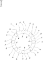
FIG. 2 is a cross-sectional view of the tubular body of the first embodiment. -
FIG. 3 is a partially enlarged view ofFIG. 2 . -
FIG. 4 is a perspective view of the tubular body of the second embodiment. -
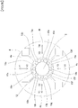
FIG. 5 is a cross-sectional view of the tubular body of the second embodiment. -
FIG. 6 is a partially enlarged view ofFIG. 5 . -
FIG. 7 is a cross-sectional view showing an initial state of setting a stranded wire to a swaging machine in producing a tubular body of the second embodiment. -
FIG. 8 is a cross-sectional view showing an intermediate state in producing the tubular body of the second embodiment. -
FIG. 9 is a cross-sectional view showing a final state in producing the tubular body of the second embodiment. -
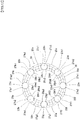
FIG. 10 is a cross-sectional view of the tubular body of the third embodiment. -
FIG. 11 is a partially enlarged view ofFIG. 10 . -
FIG. 12 is a cross-sectional view of the tubular body of the fourth embodiment. -
FIG. 13 is a partially enlarged view ofFIG. 12 . -
FIG. 14 is a cross-sectional view of the tubular body of the fifth embodiment. -
FIG. 15 is a partially enlarged view ofFIG 14 . - Hereinafter, embodiments of the present invention will be described with reference to the drawings.
- Firstly, a first embodiment of the present invention will be described.
Figure 1 is a perspective view of the tubular body of the first embodiment of the present invention,FIG. 2 is a cross-sectional view of the tubular body of the first embodiment,FIG. 3 is a partially enlarged view ofFIG. 2 . - As shown in
FIG. 1 , atubular body 1 is an elongated tubular body configured from eight first wires (3a, 3b, 3c, 3d, 3e, 3f, 3g, 3h) and eight second wires (5a, 5b, 5c, 5d, 5e, 5f, 5g, 5h) which are spirally twisted into a hollow tubular configuration so that the first wires and second wires are alternately arranged with each other and each of the first wires is placed between two adjacent second wires. - Further, the
tubular body 1 includes a substantially circular outer peripheral surface and a substantially circular inner peripheral surface in a cross-sectional view, and thetubular body 1 forms ahollow portion 6 in an inside of the inner peripheral surface thereof. - A first wire of the present embodiment (3a ∼ 3h) is substantially circular, i.e. round, in a cross-sectional view. Here, the reason why the first wires (3a ∼ 3h) are described as substantially circular and not exactly circular in a cross-sectional view depends on considering a case where the first wire is slightly deformed by the manufacturing method of the tubular body described below. However, the first wires (3a ∼ 3h) are substantively good to be circular, i.e. round, in a cross-sectional view.
- On the other hand, each of the second wires (5a ∼ 5h) of the present embodiment has a recess in a contact portion (side surface) opposite to a corresponding one of the first wires adjacent to both sides of the second wire. For example, the
second wire 5a has a recess 5ar in the contact portion (side surface) opposite to thefirst wire 3h, and a recess 5as in the contact portion (side surface) opposite to thefirst wire 3a as shown inFIG. 3 . - The
second wire 5b has a recess 5br in the contact portion (side surface) opposite to thefirst wire 3a, and a recess 5bs in the contact portion (side surface) opposite to thefirst wire 3b. Further, other second wires (5c, 5d, 5e, 5f, 5g, 5h) also have recesses 5cr, 5cs (not shown), ·····, 5hr (not shown), 5hs as will be easily understood. - The second wire (5a ∼ 5h) of the present embodiment has a convex Ogidai shape, i.e. annular segment shape or annular sector shape, (arch shape) in a cross-sectional view. For example, the
second wire 5a has an Ogidai shape (arch shape) having a convex outer arc 5ap and a convex inner arc 5aq in the cross-sectional view shown inFIG. 3 . - The
second wire 5b has an Ogidai shape (arch shape) having a convex outer arc 5bp and a convex inner arc 5bq in the cross-sectional view. Further, the other second wires (5c, 5d, 5e, 5f, 5g, 5h) also have an Ogidai shape (arch shape) having a convex outer arc and a convex inner arc in the cross-sectional view was will be easily understood. - Incidentally, in the
tubular body 1 of the present embodiment, the radially outer ends and radially inner ends of two second wires adjacent to both sides of a first wire are in contact with each other at a point of the outside and inside. For example, concerning the twosecond wires first wire 3a, the two ends of the outer side are in contact with apoint 7a, while the two ends of the inner side are also in contact with apoint 9a as shown inFIGS. 1 to 3 . - Thus, a helical pattern through
point 7a is formed on the outer surface of thetubular body 1, and a helical pattern throughpoint 9a is formed on the inner surface of thetubular body 1. - Similarly, as the radially outer ends and radially inner ends of any two second wires adjacent to each other at both sides of a corresponding one of the first wires (3b, 3c, 3d, 3e, 3f, 3g, 3h) are in contact with a point of the outer side and a point of the inner side, seven helical patterns by
point tubular body 1, and seven helical patterns bypoint tubular body 1. - Materials of the first wires (3a ∼ 3h) and second wires (5a ∼ 5h) may be stainless steel, platinum alloys, Ni-Ti-based alloys, cobalt based alloys, or the like, but are not particularly limited to those materials. Any material having a biocompatibility may be used, although stainless steel is used in the present embodiment.
- The first wires (3a ∼ 3h) and a second wires (5a ∼ 5h) may be formed of a same material as in the present embodiment, however they may also be formed of different materials. However, when the
tubular body 1 is produced by a method using a swaging machine to be described later, it is preferred that a material of the second wires (5a ∼ 5h) is softer than a material of the first wires (3a ∼ 3h). - According to the
tubular body 1 of the present embodiment, as thetubular body 1 is configured by twisting eight first wires (3a ∼ 3h) and eight second wires (5a ∼ 5h) in a hollow shape, wherein each of the first wires (3a ∼ 3h) has a substantially circular, i.e. round, cross section, and each of the second wires (5a ∼ 5h) has a recess (5ar, 5as, 5br, 5bs, 5cr ··· 5hs) in the contact portion (side surface) opposite to a corresponding one of the first wires adjacent to it, and has an Ogidai shape, i.e. annular segment shape or annular sector shape, (arch shape) having a convex outer arc (5ap, 5bp, ···, 5hp (not shown)) and a convex inner arc (5aq, 5bq, ··· 5hq (not shown)) in a cross-sectional view, it is possible to prevent a deviation between the first wires and second wires and improve a torque transmissibility and pushing force to the other end portion of thetubular body 1 when the user manipulates one end portion of thetubular body 1. Further, since the inner surface of thetubular body 1 is flat in a cross-sectional view, insertability of other medical devices into an inside of thetubular body 1 may be improved. - In the present embodiment, the number of the first wires and second wires is eight, but is not limited to eight. Two or more first wires and two or more second wires may be used in the tubular body. That is, the tubular body may comprise a plurality of first wires and a plurality of second wires.
- Next, a second embodiment of the present invention will be described.
-
Figure 4 is a perspective view of the tubular body of the second embodiment,FIG. 5 is a cross-sectional view of the tubular body of the second embodiment,FIG. 6 is a partially enlarged view ofFIG.5 . - As shown in
FIG. 4 , atubular body 10 is an elongated tubular body configured from eight first wires (13a, 13b, 13c, 13d, 13e, 13f, 13g, 13h) and eight second wires (15a, 15b, 15c, 15d, 15e, 15f, 15g, 15h) which are spirally twisted into a hollow tubular configuration so that the first wires and second wires are alternately arranged with each other and each of the first wires is placed between two adjacent second wires. - Further, the
tubular body 10 includes a substantially circular outer peripheral surface and a substantially circular inner peripheral surface in a cross-sectional view, and thetubular body 10 forms ahollow portion 16 in an inside of the inner peripheral surface thereof. - Each of the first wires (13a ∼ 13h) of the present embodiment is substantially circular, i.e. round, in a cross-sectional view. Here, the reason why the first wires (13a ∼ 13h) are described as substantially circular and not exactly circular in a cross-sectional view depends on considering a case where the first wire is slightly deformed by the manufacturing method of the tubular body described below. However, the first wires (13a ∼ 13h) are substantively good to be circular, i.e. round, in a cross-sectional view.
- On the other hand, each of the second wires (15a ∼ 15h) of the present embodiment has a recess in a contact portion (side surface) opposite to a corresponding one of the first wires adjacent to both sides of the second wire. For example, the
second wire 15a has a recess 15ar in the contact portion (side surface) opposite to thefirst wire 13h, and a recess 15as in the contact portion (side surface) opposite to thefirst wire 13a as shown inFIG. 6 . - The
second wire 15b has a recess 15br in the contact portion (side surface) opposite to thefirst wire 13a, and a recess 15bs in the contact portion (side surface) opposite to thefirst wire 13b. Further, other second wires (15c, 15d, 15e, 15f, 15g, 15h) also have recesses 15cr, 15cs (not shown), ·····, 15hr (not shown), recess 15hs as will be easily understood. - The second wire (15a ∼ 15h) of the present embodiment has a convex Ogidai shape, i.e. annular segment shape or annular sector shape, (arch shape) in a cross-sectional view. For example, the
second wire 15a has an Ogidai shape (arch shape) having a convex outer arc 15ap and a convex inner arc 15aq in the cross-sectional view as shown inFIG. 6 . - The
second wire 15b has an Ogidai shape (arch shape) having a convex outer arc 15bp and a convex inner arc 15bq in the cross-sectional view. Further, the other second wires (15c, 15d, 15e, 15f, 15g, 15h) also have an Ogidai shape (arch shape) having a convex outer arc and a convex inner arc in the cross-sectional view as will be easily understood. - Incidentally, the
tubular body 10 of the present embodiment differs from thetubular body 1 of the first embodiment in that the radially outer ends and radially inner ends of two second wires adjacent to both sides of a first wire are separated from each other. For example, an outer end 17a1 of thesecond wire 15a adjacent to one side of thefirst wire 13a, and an outer end 17a2 of thesecond wire 15b adjacent to the other side of thefirst wire 13a are spaced apart from each other, further, an inner end 19a1 of thesecond wire 15a adjacent to one side of thefirst wire 13a, and an inner end 19a2 of thesecond wire 15b adjacent to the other side of thefirst wire 13a are also spaced apart from each other as shown inFIGS. 4 to 6 . - Similarly, in the other
first wires 13b ∼ 13h, an outer end 17b1 and an outer end 17b2, an outer end 17c1 and an outer end 17c2, ···, an outer end 17g1 and an outer end 17g2, an outer end 17h1 and an outer end 17h2 are also spaced apart from each other, and an inner end 19b1 and an inner end 19b2, an inner end 19c1 and an inner end 19c2, ···, an inner end 19g1 and an inner end 19g2, an inner end 19h1 and the inner end 19h2 are also spaced apart. - Accordingly, two helical patterns per one first wire are formed on the outer surface and the inner surface of the
tubular body 10 as shown inFIG. 4 . In the present embodiment, a total of 16 helical patterns are formed on the outer surface of the tubular body10, and a total of 16 helical patterns are formed on the inner surface of thetubular body 10. - Similar to the first wires (3a ∼ 3h) and second wires (5a ∼ 5h) of the first embodiment, materials of the first wires (13a ∼ 13h) and second wires (15a ∼ 15h) may be stainless steel, platinum alloys, Ni-Ti-based alloys, cobalt based alloys, or the like, but are not particularly limited to those materials. Any material having biocompatibility may be used, although stainless steel is used in the present embodiment.
- The first wires (13a ∼ 13h) and second wires (15a ∼ 15h) may be formed of a same material as in the present embodiment, however they may also be formed of different materials. However, when
tubular body 10 is produced by a method using a swaging machine to be described later, it is preferred that a material of the second wires (15a ∼ 15h) is softer than a material of the first wires (13a ∼ 13h). - Here, a method for manufacturing the
tubular body 10 will be described. -
FIG. 7 is a cross-sectional view showing an initial state of setting a stranded wire to a swaging machine in producing the tubular body of the second embodiment,FIG. 8 is a cross-sectional view showing an intermediate state in producing the tubular body of the second embodiment, andFIG. 9 is a cross-sectional view showing a final state in producing the tubular body of the second embodiment. - Incidentally, a swaging machine used to produce the
tubular body 10 may be any swaging machine among two-split die, three-split die, four-splits die and six-slits die. In the present embodiment, a manufacturing method will be described using the swaging machine with a four-split die. - To produce the
tubular body 10, firstly, a manufacturer prepares a strandedwire 12 configured by winding eight first wires (13a ∼ 13h) of circular cross-section and eight second wires (15a ∼ 15h) of circular cross-section, wherein a diameter of each second wire is larger than a diameter of each first wire, in a spiral manner around a circumference of acore wire 2. - Then, as shown in
FIG. 7 , the manufacturer sets the strandedwire 12 to aswaging machine 4 and deforms the strandedwire 12 by operating theswaging machine 4. Specifically, the manufacturer deforms the strandedwire 12 by vibrating afirst die 4a in a direction toward Y1 and Y2, asecond die 4b in a direction toward X3 and X4, athird die 4c in direction toward Y3 and Y4, and afourth die 4d in a direction toward X1 and X2 respectively while rotating afirst die 4a, asecond die 4b, athird die 4c and afourth die 4d of swagingmachine 4 around the strandedwire 12. - When the manufacturer continues to operate the
swaging machine 4 for a predetermined time in this way, a cross-sectional shape of each of eight first wires (13a ∼ 13h) remains circular, while a cross-sectional shape of each of eight second wires (15a ∼ 15h) is deformed into an Ogidai shape (arch shape) having a larger diameter than each of the first wires (13a ∼ 13h) as shown inFIG. 8 . - Further when the manufacturer continues to operate the
swaging machine 4 for a predetermined time in this way, a cross-sectional shape of each of eight first wires (13a ∼ 13h) remains circular, while a cross-sectional shape of each of the eight second wires (15a ∼ 15h) having a larger diameter than each of the first wires(13a ∼ 13h) is deformed into a convex Ogidai shape (arch shape) in a cross-sectional view, having recesses in the contact portions adjacent to a first wire adjacent to both sides as shown inFIG. 9 . - Then, the
tubular body 10 is completed by pulling out thecore wire 2 from the strandedwire 12, after removing the strandedwire 12 from theswaging machine 4. - On the other hand, without removing the stranded
wire 12 from theswaging machine 4, when the manufacturer continues to operate theswaging machine 4 for a further predetermined time, a strandedwire 12 is completed where the radially outer ends and radially inner ends of two second wires adjacent to both sides of a first wire (13a ∼ 13h) contact each other at a point on the outside and inside of the stranded wire in a cross-sectional view. Then, thetubular body 1 as shown inFIGS. 1 to 3 is completed by pulling out thecore wire 2 from the strandedwire 12, after removing the strandedwire 12 from theswaging machine 4. - According to the
tubular body 10 of the present embodiment, as thetubular body 10 is configured by twisting eight first wires (13a ∼ 13h) and eight second wires (15a ∼ 15h) in a hollow shape, wherein each first wire (13a ∼ 13h) has a substantially circular cross section, and each second wire (15a ∼ 15h) has a recess (15ar, 15as, 15br, 15bs, 15cr ··· 15hs) in a contact portion (side surface) opposite to a corresponding one of the first wires adjacent to it, and has an Ogidai shape (arch shape) having convex outer arcs (15ap, 15bp, ···, 15hp (not shown)) and inner arcs (15aq, 15bq, ··· 15hq (not shown)) in a cross-sectional view, it is possible to prevent a deviation between the first wires and the second wires and improve a torque transmissibility and pushing force to the other end portion of thetubular body 10 when the user manipulates one end portion of thetubular body 10. - Further, since the inner surface of the
tubular body 10 is flat in a cross-sectional view, insertability of other medical devices into an inside of thetubular body 10 may be improved. - Furthermore, the
tubular body 10 of the present embodiment differs from thetubular body 1 of the first embodiment in that the radially outer ends and radially inner of two second wires adjacent to both sides of a first wire are separated from each other, so that thetubular body 10 may have a somewhat flexible structure compared to thetubular body 1 of the first embodiment. - In the present embodiment, the number of the first wires and second wires is eight, but is not limited to eight. Two or more first wires and two or more second wires may be used in the tubular body. That is, the tubular body may comprise a plurality of first wires and a plurality of second wires.
- Next, a description of a third embodiment of the present invention will be described.
-
Figure 10 is a cross-sectional view of the tubular body of the third embodiment,FIG. 11 is a partially enlarged view ofFIG. 10 . - As shown in
FIG. 10 , atubular body 20 is an elongated tubular body configured from eight first wires (23a, 23b, 23c, 23d, 23e, 23f, 23g, 23h) and eight second wires (25a, 25b, 25c, 25d, 25e, 25f, 25g, 25h) which are spirally twisted into a hollow configuration so that the first wires and second wires are alternately arranged with each other and each of the first wires is placed between two adjacent second wires. - The
tubular body 20 of the present embodiment differs from thetubular body 10 of the second embodiment in that each of the eight second wires (25a ∼ 25h) is a multi-stranded wire configured from nine third wires twisted with each other. Specifically, thesecond wire 25a is configured from nine third wires (25a1, 25a2, 25a3, 25a4, 25a5, 25a6, 25a7, 25a8, 25a9), and thesecond wire 25b is configured from nine third wires (2Sb1, 25b2, 25b3, 25b4, 25b5, 25b6, 25b7, 25b8, 25b9) as shown inFIG. 11 . - Similarly, each of the other
second wires 25c ∼ 25h is configured from nine third wires (2Sc1 ∼ 25c9, 25d1 ∼ 25d9, 25e1 ∼ 25e9, 25f1 ∼ 25f9, 25g1 ∼ 25g9, 25h1 ∼ 25h9 twisted with each other (not one part shown)). - Further, the
tubular body 20 includes a substantially circular outer peripheral surface and a substantially circular inner peripheral surface in a cross-sectional view, and thetubular body 20 forms ahollow portion 26 in an inside of the inner peripheral surface thereof. - Each of the first wires (23a ∼ 23h) of the present embodiment is substantially circular, i.e. round, in a cross-sectional view. Here, the reason why the first wires (23a ∼ 23h) are described as substantially circular and not exactly circular in a cross-sectional view depends on considering a case where the first wire is slightly deformed by the manufacturing method of the tubular body described above. However, the first wires (23a ∼ 23h) are substantively good to be circular, i.e. round, in a cross-sectional view.
- On the other hand, each of the second wires (25a ∼ 25h) of the present embodiment has a recess in a contact portion (side surface) opposite to a corresponding one of the first wires adjacent to both sides of the second wire. For example, the
second wire 25a has a recess 25ar in the contact portion (side surface) opposite to thefirst wire 23h, and a recess 25as in the contact portion (side surface) opposite to thefirst wire 23a as shown inFIG. 11 . - The
second wire 25b has a recess 25br in the contact portion (side surface) opposite to thefirst wire 23a, and a recess 25bs in the contact portion (side surface) opposite to thefirst wire 23b. Further, each of the other second wires (25c, 25d, 25e, 25f, 25g, 25h) also has recesses 25cr, 25cs (not shown), ·····, 25hr (not shown), 25hs as will be easily understood. - Each second wire (25a ∼ 25h) of the present embodiment has a convex Ogidai shape, i.e. annular segment shape or annular sector shape, (arch shape) in a cross-sectional view. For example, the
second wire 25a has an Ogidai shape (arch shape) having a convex outer arc 25ap and a convex inner arc 25aq in the cross-sectional view shown inFIG. 11 . - The
second wire 25b has an Ogidai shape (arch shape) having a convex outer arc 25bp and a convex inner arc 25bq in the cross-sectional view. Further, the other second wires (25c, 25d, 25e, 25f, 25g, 25h) also have an Ogidai shape (arch shape) having a convex outer arc and a convex inner arc in the cross-sectional view as will be easily understood. - Incidentally, the
tubular body 20 of the present embodiment is similar to thetubular body 10 of the second embodiment in that the radially outer ends and radially inner ends of two second wires adjacent to both sides of a first wire are separated from each other. For example, an outer end 27a1 of thesecond wire 25a adjacent to one side of thefirst wire 23a, and an outer end 27a2 of thesecond wire 25b adjacent to the other side of thefirst wire 23a are spaced apart from each other, further, an inner end 29a1 of thesecond wire 25a adjacent to one side of thefirst wire 23a, and an inner end 29a2 of thesecond wire 25b adjacent to the other side of thefirst wire 23a are also spaced apart from each other as shown inFIGS. 10 and11 . - Similarly, in the other
first wire 23b ∼ 23h, an outer end 27b1 and an outer end 27b2, an outer end 27c1 and an outer end 27c2, ···, an outer end 27g1 and an outer end 27g2, an outer end 27h1 and an outer end 27h2 are spaced apart from each other, an inner end 29b1 and an inner end 29b2, an inner end 29c1 and an inner end 29c2, ···, an inner end 29g1 and an inner end 29g2, an inner end 29h1 and the inner end 29h2 are also spaced apart from each other. - Accordingly, two helical patterns per one first wire are formed on the outer surface and inner surface of the
tubular body 20 as shown inFIG. 4 . In the present embodiment, a total of 16 helical patterns are formed on the outer surface of thetubular body 20, and a total of 16 helical patterns are formed on the inner surface of thetubular body 20. - Similar to the first wires and second wires of the first embodiment and second embodiment, the materials of the first wires (23a ∼ 23h) and second wires (25a ∼ 25h) may be stainless steel, platinum alloys, Ni-Ti-based alloys, cobalt based alloys, and the like, but are not particularly limited to those materials. Any material having a biocompatibility may be used, although stainless steel is used in the present embodiment.
- The first wires (23a ∼ 23h) and second wires (25a ∼ 25h) may be formed of a same material as in the present embodiment, however they may also be formed of different materials. However, when the
tubular body 20 is produced by the method using a swaging machine as described above, it is preferred that a material of the second wires (25a ∼ 25h) is softer than a material of the first wires (23a ∼ 23h). - Note that the manufacturing method of the
tubular body 20 is identical to the manufacturing method of thetubular body 10 of the second embodiment. However, instead of the second wires (15a ∼ 15h) inFIG. 7 , a stranded wire configured by twisting nine third wires each having a circular cross-section is used. - That is, the
tubular body 20 of this embodiment is produced by preparing a stranded wire configured by winding eight first wires (23a ∼ 23h) of circular cross-section and eight second wires (25a ∼ 25h) of substantially circular cross-section, wherein a diameter of a second wire is larger than a diameter of a first wire (23a ∼ 23h), in a spiral manner around the circumference of acore wire 2. - Then, when the manufacturer continues to operate the
swaging machine 4 for a predetermined time, a cross-sectional shape of each of eight first wires (23a ∼ 23h) remains circular, while a cross-sectional shape of each of eight second wires (25a ∼ 25h) having a larger diameter than each of the first wires (23a ∼ 23h) has recesses in the contact portions adjacent to a first wire adjacent to both sides and is deformed into an Ogidai shape (arch shape) as shown inFIG. 10 . Thereafter, similarly to the manufacturing method of thetubular body 10 of the second embodiment, by extracting thecore wire 2 from the stranded wire, thetubular body 20 is completed. - According to the
tubular body 20 of the present embodiment, as thetubular body 20 is configured by twisting eight first wires (23a ∼ 23h) and eight second wires (25a ∼ 25h) in a hollow shape, wherein each of first wires (23a ∼ 23h) has a substantially circular cross section, each of second wires (25a ∼ 25h) has a recess (25ar, 25as, 25br, 25bs, 25cr ··· 25hs) in a contact portion (side surface) opposite to a corresponding one of the first wires adjacent to it, and has an Ogidai shape (arch shape) having convex outer arcs (25ap, 25bp, ···, 25hp (not shown)) and inner arcs (25aq, 25bq, ··· 25hq (not shown)) in a cross-sectional view, and further each of second wires (25a ∼ 25h) is configured by twisting nine third wires (such as 25a1 ∼ 25a9) with each other, it is possible to prevent a deviation between the first wires and the second wires and improve a torque transmissibility and pushing force to the other end portion of thetubular body 20 when the user manipulates one end portion of thetubular body 20. - Further, since the inner surface of the
tubular body 20 is flat in a cross-sectional view, insertability of other medical devices into an inside of thetubular body 20 may be improved. And when the user bends thetubular body 20, a subtle movement of the third wires may improve flexibility and durability of the tubular body. - In the present embodiment, the number of the first wires and second wires is eight, but is not limited to eight. Two or more first wires and two or more second wires may be used in the tubular body. That is, the tubular body may comprise a plurality of first wires and a plurality of second wires.
- In the present embodiment, although the second wire is configured by twisting nine third wires, it is not limited to nine. Three or more third wires may be used in the tubular body.
- Next, a description of a fourth embodiment of the present invention will be described.
-
Figure 12 is a cross-sectional view of the tubular body of the fourth embodiment,FIG. 13 is a partially enlarged view ofFIG. 12 . - As shown in
FIG. 12 , atubular body 30 is an elongated tubular body configured from eight first wires (33a, 33b, 33c, 33d, 33e, 33f, 33g, 33h) and eight second wires (35a, 35b, 35c, 35d, 35e, 35f, 35g, 35h) which are spirally twisted into a hollow tubular configuration so that the first wires and second wires are alternately arranged with each other and each of the first wires is placed between two adjacent second wires. - The
tubular body 30 of the present embodiment differs from thetubular body 10 of the second embodiment in that each of the first wires (33a ∼ 33h) is configured from seven fourth wires twisted with each other. Specifically, thefirst wire 33a is configured from seven fourth wires (33a1, 33a2, 33a3, 33a4, 33a5, 33a6, 33a7), thefirst wire 3b is configured from seven fourth wires (33b1, 33b2, 33b3, 33b4, 333b5, 33b6, 33b7) as shown inFIG. 13 . - Similarly, the other
first wires 33c ∼ 33h are each configured from seven fourth wires (33c1 ∼ 33c7, 33d1 ∼ 33d7, 33e1 ∼ 33e7, 33f1 ∼ 33f7, 33g1 ∼ 33g7, 33h1 ∼ 33h7 (not one part shown)). - Further, the
tubular body 30 includes a substantially circular outer peripheral surface and a substantially circular inner peripheral surface in a cross-sectional view, and thetubular body 30 forms ahollow portion 36 in an inside of the inner peripheral surface thereof. - Further, each of the second wires (35a ∼ 35h) of the present embodiment has a recess in a contact portion (side surface) opposite to a corresponding one of the first wires adjacent to both sides of the second wire. For example, the
second wire 35a has a recess 35ar in a contact portion (side surface) opposite to thefirst wire 33h, and a recess 35as in a contact portion (side surface) opposite to thefirst wire 33a as shown inFIG. 13 . - The
second wire 35b has a recess 35br in a contact portion (side surface) adjacent to thefirst wire 33a, and a recess 35bs in a contact portion (side surface) opposite to thefirst wire 33b. Further, the other second wires (35c, 35d, 35e, 35f, 35g, 35h) also have recesses 35cr, 35cs (not shown), ·····, 35hr (not shown), 35hs as will be easily understood. - A second wire (35a ∼ 35h) of the present embodiment has a convex Ogidai shape, i.e. annular segment shape or annular sector shape, (arch shape) in a cross-sectional view. For example, the
second wire 35a has an Ogidai shape (arch shape) having a convex outer arc 35ap and a convex inner arc 35aq in the cross-sectional view shown inFIG. 13 . - The
second wire 35b has an Ogidai shape (arch shape) having a convex outer arc 35bp and a convex inner arc 35bq in the cross-sectional view. Further, the other second wires (35c, 35d, 35e, 35f, 35g, 35h) also have an Ogidai shape (arch shape) having a convex outer arc and a convex inner arc in a cross-sectional view as will be easily understood. - Incidentally, the
tubular body 30 of the present embodiment is similar to thetubular body 10 of the second embodiment in that the radially inner ends and radially outer ends of two second wires adjacent to both sides of a first wire are separated from each other. For example, an outer end 37a1 of thesecond wire 35a adjacent to one side of thefirst wire 33a, and an outer end 37a2 of thesecond wire 35b adjacent to the other side of thefirst wire 33a are spaced apart from each other, further, an inner end 39a1 of thesecond wire 35a adjacent to one side of thefirst wire 33a, and an inner end 39a2 of thesecond wire 35b adjacent to the other side of thefirst wire 33a are also spaced apart from each as shown inFIGS. 12 and13 . - Similarly, in the other
first wires 33b ∼ 33h, an outer end 37b1 and an outer end 37b2, an outer end 37cl and an outer end 37c2, ···, an outer end 37g1 and an outer end 37g2, an outer end 37h1 and an outer end 37h2 are also spaced apart from each other, and an inner end 39bl and an inner end 39b2, an inner end 39c1 and an inner end 39c2, ···, an inner end 39g1 and an inner end 39g2, an inner end 39h1 and the inner end 39h2 are also spaced apart from each other. - Accordingly, two helical patterns per one first wire are formed on the outer surface and inner surface of the
tubular body 30 as shown inFIG. 4 . In the present embodiment, a total of 16 helical patterns are formed on the outer surface of thetubular body 30, and a total of 16 helical patterns are formed on the inner surface of thetubular body 30. - Similar to the first wires and second wires of the first embodiment to third embodiment, the materials of the first wires (33a ∼ 33h) and second wires (35a ∼ 35h) may be stainless steel, platinum alloys, Ni-Ti-based alloys, cobalt based alloys, or the like, but are not particularly limited to those materials. Any material having a biocompatibility may be used, although stainless steel is used in the present embodiment.
- The first wires (33a ∼ 33h) and second wires (35a ∼ 35h) may be formed of a same material as in the present embodiment, but they may also be formed of different materials. However, when the
tubular body 30 is produced by a method using the swaging machine described before, it is preferred that a material of the second wires (35a ∼ 35h) is softer than a material of the first wires (33a ∼ 33h). - Note that the manufacturing method of the
tubular body 30 is identical to the manufacturing method of thetubular body 10 of the second embodiment. However, instead of the first wire (13a ∼ 13h) shown inFIG. 7 , a stranded wire configured by twisting seven fourth wires each having a circular cross-section is used. - That is, the
tubular body 30 of this embodiment is produced by preparing a stranded wire configured by winding eight first stranded wires (33a ∼ 33h) which are each configured from seven fourth wires of circular cross-section, and eight second wires (35a ∼ 35h) of circular cross-section, wherein a diameter of a second wire is larger than a diameter of a first wire (33a ∼ 33h), in a spiral manner around the circumference of acore wire 2. - Then, when the manufacturer continues to operate the
swaging machine 4 for a predetermined time, a cross-sectional shape of each of eight first wires (33a ∼ 33h) remains circular, while a cross-sectional shape of each of eight second wires (35a ∼ 35h) having a larger diameter than each of the first wires (33a ∼ 33h) has recesses in the contact portions adjacent to a first wire adjacent to both sides, and is deformed into an Ogidai shape (arch shape) as shown inFIG. 12 . Thereafter, similarly to the manufacturing method of thetubular body 10 of the second embodiment, by extracting thecore wire 2 from the stranded wire thetubular body 30 is completed. - According to the
tubular body 30 of the present embodiment, as thetubular body 30 is configured by twisting eight first wires (33a ∼ 33h) and eight second wires (35a ∼ 35h) into a hollow shape, wherein each of first wires (33a ∼ 33h) has a substantially circular cross section, each of second wires (35a ∼ 35h) has a recess (35ar, 35as, 35br, 35bs, 35cr ··· 35hs) in a contact portion (side surface) opposite to a corresponding one of the first wires adjacent to it, and has an Ogidai shape (arch shape) having convex outer arcs (35ap, 35bp, ···, 35hp (not shown)) and inner arcs (35aq, 35bq, ··· 35hq (not shown)) in a cross-sectional view, and further each of the first wires (33a ∼ 33h) is configured by twisting seven fourth wires (such as 33a1 ∼ 33a7), it is possible to prevent a deviation between the first wires and the second wires and improve a torque transmissibility and pushing force to the other end portion of thetubular body 30 when the user manipulates one end portion of thetubular body 30. - Further, since the inner surface of the
tubular body 30 is flat in a cross-sectional view, insertability of other medical devices into an inside of thetubular body 30 may be improved. And when the user bends thetubular body 30, a subtle movement of the fourth wires may improve flexibility and durability of the tubular body. - In the present embodiment, the number of the first wires and second wires is eight, but is not limited to eight. Two or more first wires and two or more second wires may be used in the tubular body. That is, the tubular body may comprise a plurality of first wires and a plurality of second wires.
- In the present embodiment, although a first wire is configured by twisting seven fourth wires, it is not limited to seven. Three or more fourth wires may be used in the tubular body.
- Next, a description of a fifth embodiment of the present invention will be described.
-
Figure 14 is a cross-sectional view of the tubular body of the fifth embodiment,FIG. 15 is a partially enlarged view ofFIG. 14 . - As shown in
FIG. 14 , atubular body 40 is an elongated tubular body configured from eight first wires (43a, 43b, 43c, 43d, 43e, 43f, 43g, 43h) and eight second wires (45a, 45b, 45c, 45d, 45e, 45f, 45g, 45h) which are spirally twisted into a hollow tubular configuration so that the first wires and second wires are alternately arranged with each other and each of the second wires is placed between two adjacent first wires. - The
tubular body 40 of the present embodiment differs from thetubular body 10 of the second embodiment in that each of the first wires (43a ∼ 43h) is configured from seven fourth wires twisted with each other, and each of the second wires (45a ∼ 45h) is configured from twisting nine third wires with each other. - Specifically, the
first wire 43a is configured from seven fourth wires (43a1, 43a2, 43a3, 43a4, 43a5, 43a6, 43a7), and thesecond wire 45a is configured from nine third wires (45a1, 45a2, 45a3, 45a4, 45a5, 45a6, 45a7,45a8,45a9) as shown inFIG. 15 . - Similarly, the other
first wires 43b ∼ 43h are each configured from seven fourth wires (43b1 ∼ 43b7,43c1 ∼ 43c7, 43d1 ∼ 43d7, 43e1 ∼ 43e7, 43f1 ∼ 43f7, 43g1 ∼ 43g7, 43h1 ∼ 43h7 (not one part shown)), while the othersecond wires 45b ∼ 45h are each configured from nine third wires (45b1∼ 45b9,45c1 ∼ 45c9, 45d1 ∼ 45d9, 45e1 ∼ 45e9, 45f1 ∼ 45f9, 45g1 ∼ 45g9, 45h1 ∼ 45h9 (not one part shown)). - Further, the
tubular body 40 includes a substantially circular outer peripheral surface and a substantially circular inner peripheral surface in a cross-sectional view, and thetubular body 40 forms ahollow portion 46 in an inside of the inner peripheral surface thereof. - Further, each of the second wires (45a ∼ 45h) of the present embodiment has a recess in a contact portion (side surface) opposite to a corresponding one of the first wires adjacent to both sides of the second wire. For example, the
second wire 45a has a recess 45ar in a contact portion (side surface) opposite to thefirst wire 43h, and a recess 45as in a contact portion (side surface) opposite to thefirst wire 43a as shown inFIG. 15 . - The
second wire 45b has a recess 45br in a contact portion (side surface) opposite to thefirst wire 43a, and a recess 45bs in a contact portion (side surface) opposite to thefirst wire 43b. Further, the other second wires (45c, 45d, 45e, 45f, 45g, 45h) also have recesses 45cr, ·····, 45hs as will be easily understood. - Each second wire (45a ∼ 45h) of the present embodiment has a convex Ogidai shape, i.e. annular segment shape or annular sector shape, (arch shape) in a cross-sectional view. For example, the
second wire 45a has an Ogidai shape (arch shape) having a convex outer arc 45ap and a convex inner arc 45aq in the cross-sectional view shown inFIG. 15 . - The
second wire 45b has an Ogidai shape (arch shape) having a convex outer arc 45bp and a convex inner arc 45bq in the cross-sectional view. Further, the other second wires (45c, 45d, 45e, 45f, 45g, 45h) also have an Ogidai shape (arch shape) having a convex outer arc and a convex inner arc in the cross-sectional view as will be easily understood. - Incidentally, the
tubular body 40 of the present embodiment is similar to thetubular body 10 of the second embodiment in that the radially outer ends and radially inner ends of two second wires adjacent to both sides of a first wire are separated from each other. For example, an outer end 47a1 of thesecond wire 45a adjacent to one side of thefirst wire 43a, and an outer end 47a2 of thesecond wire 45b adjacent to the other side of thefirst wire 43a are spaced apart from each other, further, an inner end 49a1 of thesecond wire 45a adjacent to one side of thefirst wire 43a, and an inner end 49a2 of thesecond wire 45b adjacent to the other side of thefirst wire 43a are also spaced apart from each other as shown inFIGS. 14 and15 . - Similarly, in the other
first wires 43b ∼ 43h, an outer end 47b1 and an outer end 47b2, an outer end 47c1 and an outer end 47c2, ···, an outer end 47g1 and an outer end 47g2, an outer end 47h1 and an outer end 47h2 are also spaced apart from each other, an inner end 49b1 and an inner end 49b2, an inner end 49c1 and an inner end 49c2, ···, an inner end 49g1 and an inner end 49g2, an inner end 49h1 and the inner end 49h2 are also spaced apart from each other. - Accordingly, two helical patterns per one first wire are formed on the outer surface and the inner surface of the
tubular body 40 as shown inFIG. 4 . In the present embodiment, a total of 16 helical patterns are formed on the outer surface of thetubular body 40, and a total of 16 helical patterns are formed on the inner surface of thetubular body 40. - Similar to the first wires and second wires of the first embodiment to fourth embodiment, the materials of the first wires (43a ∼ 43h) and second wire (45a ∼ 45h) may be stainless steel, platinum alloys, Ni-Ti-based alloys, cobalt based alloys, or the like, but are not particularly limited to those materials. Any material having a biocompatibility may be used, although stainless steel is used in the present embodiment.
- The first wires (43a ∼ 43h) and second wires (45a ∼ 45h) may be formed of a same material as in the present embodiment, however they may also be formed of different materials. However, when the
tubular body 40 is produced by a method using the swaging machine described before, it is preferred that a material of the second wires (45a ∼ 45h) is softer than a material of the first wires (43a ∼ 43h). - Note that the manufacturing method of the
tubular body 40 is identical to the manufacturing method of thetubular body 10 of the second embodiment. However, instead of the first wires (13a ∼ 13h) inFIG. 7 , a stranded wire configured by twisting seven fourth wires each having a circular cross-section is used. And instead of each of the second wires (15a ∼ 15h) inFIG. 7 , a stranded wire configured by twisting nine third wires each having a circular cross-section is used. - That is, the
tubular body 40 of this embodiment is produced by preparing a stranded wire configured by winding eight first stranded wires (43a ∼ 43h) which are each configured from seven fourth wires of circular cross-section, and eight second wires (45a ∼ 45h) of circular cross-section, wherein the diameter of a second wire is larger than a diameter of the first wire (43a ∼ 43h), in a spiral manner around the circumference of acore wire 2. - Then, when the manufacturer continues to operate the
swaging machine 4 for a predetermined time, a cross-sectional shape of each of the eight first wires (43a ∼ 43h) remains circular, while a cross-sectional shape of each of the eight second wires (45a ∼ 45h) having larger diameter than the the first wires (43a ∼ 43h) has recesses in the contact portions adjacent to the first wires adjacent to both sides, is deformed into Ogidai shape (arch shape) as shown inFIG. 14 . Thereafter, similarly to the manufacturing method of thetubular body 10 of the second embodiment, by extracting thecore wire 2 from the stranded wire, thetubular body 40 is completed. - According to the
tubular body 40 of the present embodiment, as thetubular body 40 is configured by twisting eight first wires (43a ∼ 43h) and eight second wires (45a ∼ 45h) in a hollow shape, wherein each of first wires (43a ∼ 43h) has a substantially circular cross section, each of second wires (45a ∼ 45h) has a recess (45ar, 45as, 45br, 45bs, 45cr ··· 45hs) in a contact portion (side surface) opposite to a corresponding one of the first wires adjacent to it, and has an Ogidai shape (arch shape) having convex outer arcs (45ap, 45bp, ···, 45hp (not shown)) and inner arcs (45aq, 45bq, ··· 45hq (not shown)) in the transverse plane radiation direction, and further each of first wires (43a ∼ 43h) is configured by twisting seven fourth wires (such as 43a1 ∼ 43a7), it is possible to prevent a deviation between the first wires and second wires and improve a torque transmissibility and pushing force to the other end portion of thetubular body 40 when the user manipulates one end portion of thetubular body 40. - Further, since the inner surface of the
tubular body 40 is flat in a cross-sectional view, insertability of other medical devices into an inside of thetubular body 40 may be improved. And when the user bends thetubular body 40, a subtle movement of the third wires and a subtle movement of the fourth wires may improve flexibility and durability of the tubular body. - In the present embodiment, the number of the first wires and second wires is eight each, but is not limited to eight. Two or more first wires and two or more second wires may be used in the tubular body. That is, the tubular body may comprise a plurality of first wires and a plurality of second wires.
- In the present embodiment, although a first wire is configured by twisting seven fourth wires, it is not limited to seven. Three or more fourth wires may be used in the tubular body.
- In the present embodiment, although a second wire is configured by twisting nine third wires, it is not limited to nine. Three or more third wires may be used in the tubular body.
-
- 1,10, 20, 30, 40 ··· tubular body
- 2 ··· core wire
-
3a ∼ - 4 ··· swaging machine
-
5a ∼ - 6,16,26,36,46 ··· hollow portion
-
7a ∼ 7h, 17a ∼ 17h, 27a ∼ 27h, 37a ∼ 37h, 47a ∼ 47h ··· outer ends -
9a ∼ 9h, 19a ∼ 19h, 29a ∼ 29h, 39a ∼ 39h, 49a ∼ 49h ··· inner ends
Claims (8)
- A tubular body (1) comprising:a plurality of first wires (3a, 3b, 3c, 3d, 3e, 3f, 3g, 3h), anda plurality of second wires (5a, 5b, 5c, 5d, 5e, 5f, 5g, 5h), whereinthe first wires (3a, 3b, 3c, 3d, 3e, 3f, 3g, 3h) and the second wires (5a) are twisted into a tubular configuration so that the first wires (3a, 3b, 3c, 3d, 3e, 3f, 3g, 3h) and the second wires (5a, 5b, 5c, 5d, 5e, 5f, 5g, 5h) are alternately arranged with each other and each of the second wires (5a, 5b, 5c, 5d, 5e, 5f, 5g, 5h) is placed between two adjacent first wires (3a, 3b, 3c, 3d, 3e, 3f, 3g, 3h), and whereinat least one of the first wires (3a) has a round cross section perpendicular to a longitudinal direction of the tubular body, characterized in thatat least one of the second wires (5a) has a cross section perpendicular to the longitudinal direction with a recess (5as) in a side surface opposite to the first wire (3a), and the cross section of the second wire (5a) is annular sector shaped and projects radially outwardly.
- The tubular body (20) according to claim 1, wherein
each of the first wires (3a, 3b, 3c, 3d, 3e, 3f, 3g, 3h) has a round cross section perpendicular to the longitudinal direction, and
each of the second wires (5a) has a cross section perpendicular to the longitudinal direction with a recess (5as) in one side surface opposite to the first wire (3a) and another recess (5ar) in the other side surface opposite to the other first wire (3h), and the cross section of each of the second wires (5a) is annular sector shaped and projects radially outwardly. - The tubular body (20) according to claim 1 or 2, wherein
each of the second wires (25a, 25b, 25c, 25d, 25e, 25f, 25g, 25h) is a multi-strand wire configured from a plurality of third wires (25a1, 25a2, 25a3, 25a4, 25a5, 25a6, 25a7, 25a8, 25a9) twisted with each other. - The tubular body (30) according to any one of claims 1 to 3, wherein
each of the first wires (33a, 33b, 33c, 33d, 33e, 33f, 33g, 33h) is a multi-strand wire configured from a plurality of fourth wires (33a1, 33a2, 33a3, 33a4, 33a5, 33a6, 33a7, 33a8, 33a7) twisted with each other. - The tubular body (1) according to any one of claims 1 to 4, wherein
each of the second wires (5a, 15a, 25a, 35a, 45a) is made of a material that is softer than a material of the first wires (3a, 13a, 23a, 33a, 43a). - The tubular body (1) according to claim 2, wherein
a radially outer end of the recess (5as) of the second wire (5a) contacts with a radially outer end of the recess (5br) of the adjacent second wire (5b), and
a radially inner end of the recess (5as) of the second wire (5a) contacts with a radially inner end of the recess (5br) of the adjacent second wire (5b). - The tubular body (10) according to claim 2, wherein
a radially outer end (17a1) of the recess (15as) of the second wire (15a) is spaced apart from a radially outer end (17a2) of the recess (15br) of the adjacent second wire (15b), and
a radially inner end (19a1) of the recess (15as) of the second wire (15a) is spaced apart from a radially inner end (19a2) of the recess (15br) of the adjacent second wire (15b). - A method for manufacturing a tubular body (10) according to any one of claims 1 to 7, the method comprising:twisting a plurality of first wires (13a, 13b, 13c, 13d, 13e, 13f, 13g, 13h) having a round cross section perpendicular to a longitudinal direction of the tubular body, and a plurality of second wires (15a, 15b, 15c, 15d, 15e, 15f, 15g, 15h) having a round cross section perpendicular to the longitudinal direction around a core wire (2) so that the first wires (13a, 13b, 13c, 13d, 13e, 13f, 13g, 13h) and the second wires (15a, 15b, 15c, 15d, 15e, 15f, 15g, 15h) are alternately arranged with each other and each of the second wires (15a, 15b, 15c, 15d, 15e, 15f, 15g, 15h) is placed between two of the first wires (13a, 13b, 13c, 13d, 13e, 13f, 13g, 13h), wherein a diameter of the round cross section of the second wires (15a, 15b, 15c, 15d, 15e, 15f, 15g, 15h) is greater than a diameter of the round cross section of the first wires (13a, 13b, 13c, 13d, 13e, 13f, 13g, 13h);pressing the second wires (15a) from radially outside so that the round cross section of each of the second wires (15a) is deformed into an annular sector shape projecting radially outwardly and having a recess (15as) in a side surface opposite to the first wire (13a); andpulling the core wire (2) from the tubular body (10).
Applications Claiming Priority (1)
| Application Number | Priority Date | Filing Date | Title |
|---|---|---|---|
| JP2018165635A JP7089994B2 (en) | 2018-09-05 | 2018-09-05 | Tubular body |
Publications (1)
| Publication Number | Publication Date |
|---|---|
| EP3620197A1 true EP3620197A1 (en) | 2020-03-11 |
Family
ID=67514304
Family Applications (1)
| Application Number | Title | Priority Date | Filing Date |
|---|---|---|---|
| EP19188785.0A Withdrawn EP3620197A1 (en) | 2018-09-05 | 2019-07-29 | Tubular body |
Country Status (5)
| Country | Link |
|---|---|
| US (1) | US10912929B2 (en) |
| EP (1) | EP3620197A1 (en) |
| JP (1) | JP7089994B2 (en) |
| KR (1) | KR20200027873A (en) |
| CN (1) | CN110876830B (en) |
Citations (8)
| Publication number | Priority date | Publication date | Assignee | Title |
|---|---|---|---|---|
| JPS5759519A (en) * | 1980-09-30 | 1982-04-09 | Olympus Optical Co | Quide tube for operating and drafting treating tool |
| US6258195B1 (en) * | 1999-03-19 | 2001-07-10 | Scimed Life Systems, Inc. | Multi-cord fusing manufacturing process for catheter members |
| JP2010136895A (en) | 2008-12-11 | 2010-06-24 | Kaneka Corp | Medical tube |
| EP2586483A1 (en) * | 2011-10-31 | 2013-05-01 | Asahi Intecc Co., Ltd. | Guidewire |
| EP2982405A1 (en) * | 2013-04-01 | 2016-02-10 | Terumo Kabushiki Kaisha | Coil, guide wire, and coil manufacturing method |
| US20170156745A1 (en) * | 2015-07-01 | 2017-06-08 | Olympus Corporation | Endoscope treatment tool |
| US20180071495A1 (en) * | 2016-09-14 | 2018-03-15 | Asahi Intecc Co., Ltd. | Connection structure and guide wire having the connection structure |
| JP2018108119A (en) * | 2016-12-28 | 2018-07-12 | テルモ株式会社 | Guide wire and medical coil |
Family Cites Families (23)
| Publication number | Priority date | Publication date | Assignee | Title |
|---|---|---|---|---|
| US338913A (en) * | 1886-03-30 | batchelor | ||
| US424044A (en) * | 1890-03-25 | Thomas e | ||
| US969660A (en) * | 1909-06-10 | 1910-09-06 | Franz Schmidt | Flexible shaft. |
| US1164521A (en) * | 1914-05-18 | 1915-12-14 | Otto P Houben | Protective covering or armor. |
| US2087876A (en) * | 1933-10-19 | 1937-07-20 | American Steel & Wire Co | Annular strand |
| DE671776C (en) * | 1935-11-28 | 1939-02-15 | Heinrich Oechslin | Wire rope or stranded wire with an outer layer of profile wires |
| US3445586A (en) * | 1966-12-30 | 1969-05-20 | Aluminium Lab Ltd | Loose-core conductor having improved self-damping combined with improved internal wear resistance |
| CA1005366A (en) * | 1972-12-08 | 1977-02-15 | Institut Francais Du Petrole | Flexible proofed conduit |
| US5169729A (en) * | 1987-04-28 | 1992-12-08 | Pirelli Coordinamento Pneumatici S.P.A. | Beads of pneumatic tires for vehicle wheels |
| US6137060A (en) * | 1997-05-02 | 2000-10-24 | General Science And Technology Corp | Multifilament drawn radiopaque highly elastic cables and methods of making the same |
| EP1195174B1 (en) * | 2000-10-03 | 2005-01-26 | William Cook Europe ApS | A guide wire |
| US6881194B2 (en) * | 2001-03-21 | 2005-04-19 | Asahi Intec Co., Ltd. | Wire-stranded medical hollow tube, and a medical guide wire |
| US20050154400A1 (en) | 2003-12-18 | 2005-07-14 | Asahi Intecc Co., Ltd | Medical treating tool |
| JP2005230132A (en) | 2004-02-18 | 2005-09-02 | Asahi Intecc Co Ltd | Medical treatment tool |
| JP4810388B2 (en) | 2006-10-03 | 2011-11-09 | 三洲電線株式会社 | Twisted wire conductor and manufacturing method thereof |
| JP5410275B2 (en) * | 2007-05-21 | 2014-02-05 | 株式会社ブリヂストン | Pneumatic tire |
| EP2183426A1 (en) * | 2007-09-06 | 2010-05-12 | NV Bekaert SA | Steel rope safety system with compacted ropes |
| JP5110716B2 (en) * | 2011-02-25 | 2012-12-26 | 朝日インテック株式会社 | catheter |
| ITPD20130081A1 (en) * | 2013-03-29 | 2014-09-30 | Gioachino Coppi | CATHETER WITH CONTROLLED DEFORMATION |
| JP2015159865A (en) * | 2014-02-26 | 2015-09-07 | 朝日インテック株式会社 | Guide wire |
| JP6344762B2 (en) * | 2014-05-21 | 2018-06-20 | 朝日インテック株式会社 | catheter |
| JP6624600B2 (en) * | 2015-03-23 | 2019-12-25 | 朝日インテック株式会社 | catheter |
| CN206688006U (en) * | 2016-12-26 | 2017-12-01 | 上海英诺伟医疗器械有限公司 | A kind of non-vascular cavity seal wire |
-
2018
- 2018-09-05 JP JP2018165635A patent/JP7089994B2/en active Active
-
2019
- 2019-02-14 KR KR1020190017258A patent/KR20200027873A/en not_active Withdrawn
- 2019-04-03 US US16/374,747 patent/US10912929B2/en not_active Expired - Fee Related
- 2019-05-15 CN CN201910402738.3A patent/CN110876830B/en active Active
- 2019-07-29 EP EP19188785.0A patent/EP3620197A1/en not_active Withdrawn
Patent Citations (8)
| Publication number | Priority date | Publication date | Assignee | Title |
|---|---|---|---|---|
| JPS5759519A (en) * | 1980-09-30 | 1982-04-09 | Olympus Optical Co | Quide tube for operating and drafting treating tool |
| US6258195B1 (en) * | 1999-03-19 | 2001-07-10 | Scimed Life Systems, Inc. | Multi-cord fusing manufacturing process for catheter members |
| JP2010136895A (en) | 2008-12-11 | 2010-06-24 | Kaneka Corp | Medical tube |
| EP2586483A1 (en) * | 2011-10-31 | 2013-05-01 | Asahi Intecc Co., Ltd. | Guidewire |
| EP2982405A1 (en) * | 2013-04-01 | 2016-02-10 | Terumo Kabushiki Kaisha | Coil, guide wire, and coil manufacturing method |
| US20170156745A1 (en) * | 2015-07-01 | 2017-06-08 | Olympus Corporation | Endoscope treatment tool |
| US20180071495A1 (en) * | 2016-09-14 | 2018-03-15 | Asahi Intecc Co., Ltd. | Connection structure and guide wire having the connection structure |
| JP2018108119A (en) * | 2016-12-28 | 2018-07-12 | テルモ株式会社 | Guide wire and medical coil |
Also Published As
| Publication number | Publication date |
|---|---|
| US10912929B2 (en) | 2021-02-09 |
| KR20200027873A (en) | 2020-03-13 |
| CN110876830A (en) | 2020-03-13 |
| JP2020036772A (en) | 2020-03-12 |
| CN110876830B (en) | 2023-05-30 |
| US20200069918A1 (en) | 2020-03-05 |
| JP7089994B2 (en) | 2022-06-23 |
Similar Documents
| Publication | Publication Date | Title |
|---|---|---|
| JP7304424B2 (en) | catheter | |
| US9192493B2 (en) | Medical stent having a marker coil | |
| CN109843224B (en) | Rotationally twistable intravascular device with actuatable working end | |
| EP2564756B1 (en) | Endoscope | |
| JP5954747B2 (en) | catheter | |
| CN111228637B (en) | Catheter tube | |
| EP3245984B1 (en) | Stent and stent graft | |
| US10603471B2 (en) | Medical guide wire | |
| EP2921195A1 (en) | Guide wire | |
| US6818076B1 (en) | Multi-strand coil spring | |
| CN111672010A (en) | microcatheter | |
| US20090204118A1 (en) | Surgical cable with malleable leader segment | |
| US5947979A (en) | Wire loop type instrument for endoscope and method of producing the same | |
| CN107735526B (en) | operating rope | |
| JP7050175B2 (en) | Medical equipment | |
| CN110876830B (en) | Tubular body | |
| JP6515012B2 (en) | Guide wire | |
| EP4659715A1 (en) | Production method for string-equipped stent, string-equipped stent, and stent delivery device | |
| CN117339081B (en) | A multidirectional adjustable bendable microcatheter and its manufacturing method | |
| JP3215809B2 (en) | Wire loop type treatment instrument for endoscope | |
| CN113057774B (en) | Visualization structure, implantation instrument and blood vessel support | |
| CN113116610B (en) | Developing structure and blood vessel support | |
| CN121512630A (en) | Thrombus-capturing stent and its manufacturing method | |
| JPH0975299A (en) | Reticulated tube for flexible tube of endoscope | |
| CN119867831A (en) | Adjustable curved sheath pipe |
Legal Events
| Date | Code | Title | Description |
|---|---|---|---|
| PUAI | Public reference made under article 153(3) epc to a published international application that has entered the european phase |
Free format text: ORIGINAL CODE: 0009012 |
|
| STAA | Information on the status of an ep patent application or granted ep patent |
Free format text: STATUS: THE APPLICATION HAS BEEN PUBLISHED |
|
| AK | Designated contracting states |
Kind code of ref document: A1 Designated state(s): AL AT BE BG CH CY CZ DE DK EE ES FI FR GB GR HR HU IE IS IT LI LT LU LV MC MK MT NL NO PL PT RO RS SE SI SK SM TR |
|
| AX | Request for extension of the european patent |
Extension state: BA ME |
|
| STAA | Information on the status of an ep patent application or granted ep patent |
Free format text: STATUS: REQUEST FOR EXAMINATION WAS MADE |
|
| 17P | Request for examination filed |
Effective date: 20200805 |
|
| RBV | Designated contracting states (corrected) |
Designated state(s): AL AT BE BG CH CY CZ DE DK EE ES FI FR GB GR HR HU IE IS IT LI LT LU LV MC MK MT NL NO PL PT RO RS SE SI SK SM TR |
|
| STAA | Information on the status of an ep patent application or granted ep patent |
Free format text: STATUS: EXAMINATION IS IN PROGRESS |
|
| 17Q | First examination report despatched |
Effective date: 20231025 |
|
| STAA | Information on the status of an ep patent application or granted ep patent |
Free format text: STATUS: THE APPLICATION HAS BEEN WITHDRAWN |
|
| 18W | Application withdrawn |
Effective date: 20240208 |