EP3620091B1 - Scharniervorrichtung für toilette - Google Patents
Scharniervorrichtung für toilette Download PDFInfo
- Publication number
- EP3620091B1 EP3620091B1 EP19195596.2A EP19195596A EP3620091B1 EP 3620091 B1 EP3620091 B1 EP 3620091B1 EP 19195596 A EP19195596 A EP 19195596A EP 3620091 B1 EP3620091 B1 EP 3620091B1
- Authority
- EP
- European Patent Office
- Prior art keywords
- damper
- toilet
- catch
- ring
- ear
- Prior art date
- Legal status (The legal status is an assumption and is not a legal conclusion. Google has not performed a legal analysis and makes no representation as to the accuracy of the status listed.)
- Active
Links
Images




Classifications
-
- A—HUMAN NECESSITIES
- A47—FURNITURE; DOMESTIC ARTICLES OR APPLIANCES; COFFEE MILLS; SPICE MILLS; SUCTION CLEANERS IN GENERAL
- A47K—SANITARY EQUIPMENT; ACCESSORIES THEREFOR, e.g. TOILET ACCESSORIES
- A47K13/00—Seats or covers for all kinds of closets
- A47K13/04—Buffers for seats
-
- A—HUMAN NECESSITIES
- A47—FURNITURE; DOMESTIC ARTICLES OR APPLIANCES; COFFEE MILLS; SPICE MILLS; SUCTION CLEANERS IN GENERAL
- A47K—SANITARY EQUIPMENT; ACCESSORIES THEREFOR, e.g. TOILET ACCESSORIES
- A47K13/00—Seats or covers for all kinds of closets
- A47K13/10—Devices for raising and lowering ; Collapsible or rotating seats or covers
-
- A—HUMAN NECESSITIES
- A47—FURNITURE; DOMESTIC ARTICLES OR APPLIANCES; COFFEE MILLS; SPICE MILLS; SUCTION CLEANERS IN GENERAL
- A47K—SANITARY EQUIPMENT; ACCESSORIES THEREFOR, e.g. TOILET ACCESSORIES
- A47K13/00—Seats or covers for all kinds of closets
- A47K13/12—Hinges
-
- E—FIXED CONSTRUCTIONS
- E03—WATER SUPPLY; SEWERAGE
- E03D—WATER-CLOSETS OR URINALS WITH FLUSHING DEVICES; FLUSHING VALVES THEREFOR
- E03D5/00—Special constructions of flushing devices, e.g. closed flushing system
- E03D5/02—Special constructions of flushing devices, e.g. closed flushing system operated mechanically or hydraulically (or pneumatically) also details such as push buttons, levers and pull-card therefor
- E03D5/04—Special constructions of flushing devices, e.g. closed flushing system operated mechanically or hydraulically (or pneumatically) also details such as push buttons, levers and pull-card therefor directly by the seat or cover combined with devices for opening and closing shutters in the bowl outlet and/or with devices for raising and lowering seat or cover; Raising or lowering seat and/or cover by flushing or by the flushing mechanism
Definitions
- the present invention relates to a toilet hinge arrangement comprising a toilet cover assembly for fastening to a toilet bowl.
- a further aspect is that in many cases it is desirable to be able to easily remove the toilet cover assembly and for this reason a number of systems exist where the hinge mechanism may easily be manipulated in order to release the hinge mechanism from the toilet bowl in order to remove the toilet cover assembly.
- toilet cover assemblies tend to be very closely assembled in the hinge arrangements in order to provide a stable and controlled movement of the seat/cover relative to the toilet bowl in order to give the user a feeling of quality.
- the invention addresses this by providing a toilet hinge arrangement according to claim 1.
- the adaptor ring will centrally have an opening adapted to accommodate the shaft of the damper in such a manner that the rotational forces from the cover/seat will be transferred to the damper shaft if the adaptor ring is engaging the engagement surfaces on the seat/cover as explained above.
- the damper may be suitable for use with a number of various seats or covers and at the same time the apertures and cavities provided in the ear lugs of the seat/cover may be formed substantially freely in that the catch ring and/or adaptor ring shall be shaped such that they will work as interface between the damper shaft and the interior surfaces and engagement surfaces of the ear lugs.
- the catch cavities have a substantially partly spiral surface initiating at the inner surface of the through-going aperture with increased distance to the rotation axis said substantially spiral surface terminating in a further engagement side arranged radially relative to the rotation axis, such that as the catch ring is inserted into the through-going aperture the spring action catches will expand into the catch cavities and the terminal ends of the spring catches will engage the engagement side.
- At least two catch cavities are provided, and where the substantially partly spiral surfaces are arranged with opposite orientation.
- the feature of having the spiral surfaces in opposite directions/orientation is advantageous in that the spring action catches when engaging the engagement sides of the cavities will engage and thereby block rotation in both directions of the ear lug relative to the catch ring.
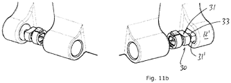
- the adaptor ring has two parallel engagement surfaces arranged symmetrically around the axis of rotation, and where two corresponding engagement surfaces are provided on the inner side of the cavity of the outermost ear lug.
- the engagement means for engaging fastening means on the toilet bowl, provided in the opposite end of the damper comprises a radial bore adapted in use to receive a mounting pin mounted on the toilet bowl, where said pin adjacent a distal end is provided with at least one circumferential groove, and where the damper in the end opposite from the end from where the damper shaft extends is provided with a slit perpendicular to the axis of the bore, such that when the pin is inserted in the bore, the circumferential groove will be positioned superposed the slit, such that a lock tab may be inserted in the slit, and engaging at least a part of said circumferential groove, thereby retaining the pin relative to the damper.
- damper shaft and the catch ring and/or adaptor ring are removably fitted on the damper shaft by a snap feature.
- This snap feature may for example be in the shape of grooves or indentations provided in the shaft of the damper and corresponding protrusions or ridges provided in the catch ring and/or adaptor ring.
- the catch ring, and the adapter ring and the resilient member are one integrated unit.
- the catch ring comprises a body section and a separate resilient member, where the separate resilient member is fitted in tracks in the body section, such that a part of the separate resilient member extends past the periphery of the body section, in use extending into catch cavities in an ear lug.
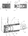
- figure 1 is illustrated the rear side of a part of a seat 10 and a cover 12 where the rear part of the seat and cover respectively is provided with ear lugs 11, 13.
- the ear lugs 11, 13 are provided with a cavity 14, 15.
- the cavity is suitable to accommodate a damper assembly 20 as will be explained with reference to figures 3a-3b .
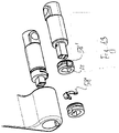
- the damper assembly 20 is illustrated in an assembled situation in figure 3a and in an exploded view as illustrated in figure 3b .
- the damper assembly comprises five main parts.
- the damper 22 is provided with a damper shaft 24 which extends from one end of the damper 22.
- the damper shaft 24 may rotate around a central axis 100 illustrated by a dashed line.
- a toilet cover assembly will be provided with two hinge arrangements and as such the central axis 100 will pass through the rotation axis of both hinges in order to create a coordinated pivotable movement of the toilet cover assembly, i.e. the toilet seat and the toilet seat cover.
- damper 22 In the opposite end of the damper shaft 24 the damper 22 is provided with engagement means 26 such that the damper may be fastened to a corresponding fastening means extending from the toilet bowl.
- This fastening concept will be explained with reference to figure 4, 5 and 6 .
- a catch ring 28 and an adaptor ring 30 On the damper shaft 24 is arranged a catch ring 28 and an adaptor ring 30.
- the seat may now only be rotated by also rotating the damper shaft 24 such that the dampening action provided by the damper 22 is transferred to the seat.
- the adaptor ring 30 which is also mounted on the damper shaft 24 is not provided with engagement rings such that the cover may pivot freely relative to the adaptor ring.
- ridges 36, 38 may be provided in the catch ring and the adaptor ring respectively, and corresponding grooves 40, 42 are provided in the damper shaft 24.
- the engagement means 26 are as will be explained with reference to figures 4, 5 and 6 suitable to engage and lock onto a hinge pin 50.
- the hinge pin 50 has a diameter such that it may be inserted into the aperture 26' provided in the damper 22.
- the hinge pin 50 has a number of grooves 51, 52, 53 which serve various purposes.
- the lowermost groove 53 accommodates a stabilizing O-ring such that as the hinge pin 50 is inserted in the aperture 26', the stabilizing O-ring 53' having an outer diameter slightly larger than the diameter of the hinge pin will engage the walls of the aperture 26' thereby creating a stable fit between the hinge pin and the damper 22.
- a friction spring which as the hinge pin 50 is inserted in the aperture 26' will be slightly compressed thereby offering a slight resistance, but once the hinge pin is completely inserted into the damper aperture 26' the friction spring will help to retain the hinge pin in a stabilized manner relative to the aperture 26'.
- the groove 51 is a locking groove such that when the hinge pin 50 is completely inserted into the aperture 26' as illustrated in figure 5 a lock tab 56 may be inserted radially relative to the hinge pin in a direction corresponding to the central axis 100 such that the lock tab 56 will engage the locking groove thereby fixing the damper relative to the hinge pin 50.
- the damper 22 is mounted to the hinge pin 50 in a firm and stable manner.
- the hinge pin 50 is fully inserted into the aperture 26' and the stabilizing O-ring 53' engages the sides of the aperture and the friction spring accommodated in the groove 52 furthermore stabilizes and assists in holding the hinge pin relative to the aperture 26'.
- the lock tab 56 is fully inserted and engaging the locking groove 51 such that the damper 22 is held by the hinge pin 50.
- the hinge pin is by its own means mounted to the toilet bowl and in this manner the toilet cover assembly is fixed in a releasable manner due to the releasable action of the lock tab to the toilet bowl.
- FIGS 2a and 2b is illustrated how the catch ring 28 co-operates with an ear lug 11, 13.
- the ear lug 11 one or more, in this embodiment two catch cavities 34 are provided.
- Each catch cavity has a spirally curved surface 41 connecting with an engagement side 43.
- the resilient spring action catches 32 provided on the catch ring will when assembled as illustrated in fig 2b expand into the catch cavities 34, thereby coupling the ear lugs 11, 13 to the catch ring 28.
- the resilient member 35 may be seen centrally in the assembly.
- figure 9 is illustrated a cross section of part of a left-hand and a right-hand damper assembly where the damper shaft 24 is provided with both a catch ring 28 and an adaptor ring 30.
- FIG 10 an isometric schematic illustration of the left-hand side damper assembly illustrated in figure 9 is illustrated in a situation where it is ready to be mounted on the ear lugs 11, 13 of same side of the cover and the seat respectively.
- the through-going aperture 14 provided in the ear lug 11 is provided with catch cavities 34.
- the catch ring 28 will therefore when inserted in the through-going aperture 14 be expanded such that the spring action catches 32 will expand into the catch cavities 34 thereby locking the ear lug 11 relative to the catch ring 28 whereby any rotation of the ear lug 11 due to the engagement of the catch ring 28 by means of the spring action catch's 32 engagement with the catch cavities 34 transfer any rotational force to the damper 22.
- the ear lug 13 is provided with a cavity which in a cross-section has a circular cross-section such that the engagement surfaces 31 of the adapter ring 30 are not locked relative to the ear lug 13 such that the ear lug 13 may rotate freely with respect to the adaptor ring 30. Therefore, in this embodiment the left-hand side as illustrated in figure 10 will transfer rotational forces from the seat's ear lug 11 to the damper 22 whereby the left-hand side cover ear lug 13 is not influenced by the damper and therefore may move freely with respect to the damper mounted in the left-hand side of the toilet seat arrangement as illustrated in figure 9 .
- the adaptor ring 30 will fit inside a cavity having parallel sides 31', 33' such that the engagement surfaces 31, 33 will engage and be held by corresponding surfaces 31', 33' provided inside the cavity provided in the ear lug 13'.
- the catch ring 28 is comprises a body section 28' provided with a track or groove 55 in a peripheral side face.
- a separate resilient member 58 fits inside the track/groove 55, such that in use the resilient member 58 being provided with a bend 57, where said bend 57 engages one or more catch cavities provided in the ear lug 11, 13.
- fig. 13 a similar embodiment is depicted where the separate resilient member 58' is a clip-structure, but has the same function as described above with respect to fig. 12a, fig. 12b and fig. 12c .
Landscapes
- Health & Medical Sciences (AREA)
- Public Health (AREA)
- Engineering & Computer Science (AREA)
- Mechanical Engineering (AREA)
- Aviation & Aerospace Engineering (AREA)
- Life Sciences & Earth Sciences (AREA)
- Hydrology & Water Resources (AREA)
- Water Supply & Treatment (AREA)
- Toilet Supplies (AREA)
Claims (7)
- Toilettenscharnieranordnung, umfassend eine Toilettendeckelbaugruppe, die einen Toilettensitz (10) und einen Toilettensitzdeckel (12) Deckel zum Befestigen an einer Toilettenschüssel enthält, wobei mittels der Toilettenscharnieranordnung, der Toilettensitz (10) und der Toilettensitzdeckel (12) um eine Mittelachse schwenken können, wobei die Toilettenscharnieranordnung umfasst:einen Drehdämpfer, wobei der Dämpfer (22) eine Schwenkachse parallel zur Mittelachse (100) aufweist, wobei der Dämpfer (22) ein Gehäuse aufweist, das den Dämpfungsmechanismus umschließt, sodass sich ein Dämpferschaft (24) außerhalb des Gehäuses in einem Ende erstreckt, und Eingriffsmittel (26) zum Eingriff mit Befestigungsmitteln an der Toilettenschüssel am gegenüberliegenden Ende des Dämpfers (22) vorgesehen sind;einen Klinkenring (28), der ausgelegt ist, um an dem Teil des Dämpferschafts (24) montiert und dadurch gehalten zu werden, der sich von dem Dämpfergehäuse erstreckt, wobei der Klinkenring (28) einen zentralen Körper aufweist, wobei sich eine oder mehrere Federklinken (32) elastisch von dem zentralen Körper erstrecken, wobei die Federklinken (32) in Richtung des zentralen Körpers gedrückt werden können, sodass die eine oder mehreren Federklinken (32) innerhalb eines Außenumfangs des zentralen Körpers liegen;einen Adapterring (30), der ausgelegt ist, um an dem Teil des Dämpferschafts (24) montiert und von diesem gehalten zu werden, der sich von dem Dämpfergehäuse erstreckt und an dem Klinkenring (28) anliegt, und wobei gegenüber der Seite, die an dem Klinkenring (28) anliegt, ein elastisches Element bereitgestellt ist, wobei das elastische Element von dem Adapterring (30) weg in einer Richtung parallel zur Mittelachse vorgespannt ist, und wobei der Adapterring (30) mit mindestens einer Eingriffsfläche (31) versehen ist;und wobei der Toilettensitz (10) und der Toilettensitzdeckel (12) jeweils mit zwei Ösenlaschen (11, 13) versehen sind, wobei jeweils eine an jede Seite des Toilettensitzes (10) beziehungsweise des Toilettensitzdeckels (12) angrenzt, wobei die Ösenlaschen des Toilettensitzes entweder innerhalb oder außerhalb der Ösenlaschen des Toilettensitzdeckels angeordnet sind, wobei die innersten Ösenlaschen mit durchgehenden Öffnungen (14) versehen sind und die äußersten Ösenlaschen mit Hohlräumen (15) versehen sind, wobei die Hohlräume (15) eine Bodenwand aufweisen, wobei die durchgehenden Öffnungen und die Hohlräume koaxial mit dem Dämpfer (22), dem Klinkenring (28) und dem Adapterring (30) angeordnet sind und einen Teil davon bedecken, und wobei das Ende des Dämpfers mit den Eingriffsmitteln nicht von den Ösenlaschen (11, 13) bedeckt ist; wobei auf einer Seite der Toilettendeckelbaugruppe eine oder mehrere der Federklinken (32) in eine oder mehrere Klinkenhohlräume (34) eingesetzt werden, die auf der Innenseite der durchgehenden Öffnung vorgesehen sind, die in den innersten Ösenlaschen vorgesehen ist, wodurch die Ösenlasche (11, 13) lösbar am Schaft (24) des Dämpfers befestigt wird, und auf der gegenüberliegenden Seite die Eingriffsfläche des Adapterrings (30) mit einer Innenseite des Hohlraums der äußersten Ösenlasche in Eingriff steht; und das elastische Element an dem Adapterring in elastischem Eingriff mit der Bodenwand von mindestens einer der äußersten Ösenlaschen steht.
- Toilettenscharnieranordnung nach Anspruch 1, wobei die Klinkenhohlräume (34) eine im Wesentlichen teilweise spiralförmige Oberfläche (41) aufweisen, die an der Innenfläche der durchgehenden Öffnung mit vergrößertem Abstand zur Drehachse beginnt, wobei die im Wesentlichen spiralförmige Oberfläche (41) in einer radial zur Rotationsachse angeordneten weiteren Eingriffsseite (43) endet, so dass, wenn der Klinkenring (28) in die Durchgangsöffnung eingesetzt wird, die Federklinken (32) sich in die Klinkenhohlräume (34) spreizen und die abschließenden Enden der Federklinken in die Eingriffsseite (43) eingreifen.
- Toilettenscharnieranordnung nach Anspruch 2, wobei mindestens zwei Klinkenhohlräume (34) bereitgestellt sind und wobei die im Wesentlichen teilweise spiralförmigen Oberflächen (41) mit entgegengesetzter Orientierung angeordnet sind.
- Toilettenscharnieranordnung nach Anspruch 1, wobei der Adapterring (30) zwei symmetrisch um die Drehachse angeordnete parallele Eingriffsflächen (31, 33) aufweist und wobei zwei entsprechende Eingriffsflächen (31', 33') an der Innenseite des Hohlraums der äußersten Ösenlasche bereitgestellt sind.
- Toilettenscharnieranordnung nach Anspruch 1, wobei die am gegenüberliegenden Ende des Dämpfers bereitgestellte Eingriffseinrichtung (26) zum Eingreifen mit einer Befestigungseinrichtung an der Toilettenschüssel eine radiale Bohrung (26') umfasst, die im Gebrauch dazu ausgelegt ist, einen Montagestift (50) aufzunehmen, der an der Toilettenschüssel montiert ist, wobei der Stift (50) benachbart zu einem distalen Ende mit mindestens einer Umfangsnut (51, 52, 53) versehen ist, und wobei der Dämpfer an dem Ende gegenüber dem Ende, von dem sich der Dämpferschaft erstreckt, mit einem Schlitz senkrecht zur Achse der radialen Bohrung versehen ist, so dass, wenn der Stift in die radiale Bohrung (26') eingeführt wird, die Umfangsnut so positioniert wird, dass sie den Schlitz überlagert, so dass ein Verriegelungsvorsprung (56) in den Schlitz eingeführt werden kann und mit mindestens einem Teil der Umfangsnut in Eingriff stehen kann, wodurch der Stift relativ zum Dämpfer gehalten wird.
- Toilettenscharnieranordnung nach Anspruch 1, wobei der Dämpferschaft (24) und der Klinkenring (28) und/oder Adapterring (30) durch ein Schnappmerkmal entfernbar auf dem Dämpferschaft (24) angebracht sind.
- Toilettenscharnieranordnung nach einem der Ansprüche 1 bis 6, wobei der Klinkenring (28) einen Körperabschnitt (28') und ein separates elastisches Element (56, 56') umfasst, wobei das separate elastische Element in Bahnen in dem Körperabschnitt angebracht ist, so dass sich ein Teil des separaten elastischen Elements über den Umfang des Körperabschnitts hinaus erstreckt und sich im Gebrauch in Klinkenhohlräume in einer Ösenlasche (11, 13) erstreckt.
Applications Claiming Priority (1)
| Application Number | Priority Date | Filing Date | Title |
|---|---|---|---|
| DKPA201870573A DK180056B1 (en) | 2018-09-05 | 2018-09-05 | Toilet hinge arrangement |
Publications (2)
| Publication Number | Publication Date |
|---|---|
| EP3620091A1 EP3620091A1 (de) | 2020-03-11 |
| EP3620091B1 true EP3620091B1 (de) | 2022-11-02 |
Family
ID=67874330
Family Applications (1)
| Application Number | Title | Priority Date | Filing Date |
|---|---|---|---|
| EP19195596.2A Active EP3620091B1 (de) | 2018-09-05 | 2019-09-05 | Scharniervorrichtung für toilette |
Country Status (3)
| Country | Link |
|---|---|
| EP (1) | EP3620091B1 (de) |
| CN (1) | CN211883584U (de) |
| DK (1) | DK180056B1 (de) |
Families Citing this family (2)
| Publication number | Priority date | Publication date | Assignee | Title |
|---|---|---|---|---|
| CN121730649A (zh) * | 2021-11-30 | 2026-03-27 | 佛山市法恩洁具有限公司 | 一种马桶盖专用铰链结构及马桶 |
| CN117398012B (zh) * | 2023-11-13 | 2025-10-17 | 厦门倍杰特科技有限公司 | 一种马桶盖板的连接组件 |
Family Cites Families (2)
| Publication number | Priority date | Publication date | Assignee | Title |
|---|---|---|---|---|
| CN102764095B (zh) * | 2012-06-21 | 2014-10-08 | 彭东 | 一种马桶盖板与座体的连接锁固装置 |
| DK179102B1 (en) * | 2016-05-04 | 2017-10-30 | Pressalit As | Hinge arrangement for toilet seat and/or cover |
-
2018
- 2018-09-05 DK DKPA201870573A patent/DK180056B1/en active IP Right Grant
-
2019
- 2019-09-05 CN CN201921471064.4U patent/CN211883584U/zh active Active
- 2019-09-05 EP EP19195596.2A patent/EP3620091B1/de active Active
Also Published As
| Publication number | Publication date |
|---|---|
| EP3620091A1 (de) | 2020-03-11 |
| CN211883584U (zh) | 2020-11-10 |
| DK201870573A1 (en) | 2020-02-14 |
| DK180056B1 (en) | 2020-02-14 |
Similar Documents
| Publication | Publication Date | Title |
|---|---|---|
| JP4729277B2 (ja) | ツール装置の保護フード構造 | |
| CN110435505B (zh) | 用于车辆的座椅倾斜器 | |
| EP3620091A1 (de) | Scharniervorrichtung für toilette | |
| JP5579685B2 (ja) | 車両用ミラー装置 | |
| CA2454639C (en) | Reinforced apparatus for a lever handle of a door lock | |
| JP2012102870A (ja) | 制御ケーブルの鞘を取付けブラケットに固定するためのクイックフィット固定装置 | |
| JP5538944B2 (ja) | 可変ダイヤル錠 | |
| US6735825B1 (en) | Secured pen and holder | |
| EP3314350B1 (de) | Montageanordnung für ein steuerpedal eines kraftfahrzeugs | |
| JPWO2018061580A1 (ja) | ロック機構を備えた着脱装置、およびそれを用いたヒンジ装置 | |
| US20200270899A1 (en) | Lock | |
| JP2022077212A (ja) | 遠心ブレーキ | |
| JP2018194092A (ja) | 双方向トルクリミッタ | |
| EP3241473B1 (de) | Scharnieranordnung für toilettensitz und/oder abdeckung | |
| EP2661205B1 (de) | Gelenkvorrichtung an einer toilette | |
| JPH0626694Y2 (ja) | 家具用つまみ | |
| CN223063262U (zh) | 淋浴控制盒 | |
| US11523719B2 (en) | Device for mounting a toilet seat assembly to and from a toilet bowl | |
| JP6999278B2 (ja) | ハンドル及びハンドルを備えた水栓 | |
| CN120323863A (zh) | 用于坐便器配件的装配装置 | |
| CN118815980B (zh) | 淋浴控制盒 | |
| CN223248084U (zh) | 智能马桶盖板的快拆结构 | |
| JP2012106590A (ja) | 車両用フードクッション装置 | |
| WO2021109082A1 (en) | Improved hinge for a toilet lid/seat | |
| JPWO2019198640A1 (ja) | ヒンジ装置 |
Legal Events
| Date | Code | Title | Description |
|---|---|---|---|
| PUAI | Public reference made under article 153(3) epc to a published international application that has entered the european phase |
Free format text: ORIGINAL CODE: 0009012 |
|
| STAA | Information on the status of an ep patent application or granted ep patent |
Free format text: STATUS: THE APPLICATION HAS BEEN PUBLISHED |
|
| AK | Designated contracting states |
Kind code of ref document: A1 Designated state(s): AL AT BE BG CH CY CZ DE DK EE ES FI FR GB GR HR HU IE IS IT LI LT LU LV MC MK MT NL NO PL PT RO RS SE SI SK SM TR |
|
| AX | Request for extension of the european patent |
Extension state: BA ME |
|
| STAA | Information on the status of an ep patent application or granted ep patent |
Free format text: STATUS: REQUEST FOR EXAMINATION WAS MADE |
|
| 17P | Request for examination filed |
Effective date: 20200910 |
|
| RBV | Designated contracting states (corrected) |
Designated state(s): AL AT BE BG CH CY CZ DE DK EE ES FI FR GB GR HR HU IE IS IT LI LT LU LV MC MK MT NL NO PL PT RO RS SE SI SK SM TR |
|
| GRAP | Despatch of communication of intention to grant a patent |
Free format text: ORIGINAL CODE: EPIDOSNIGR1 |
|
| STAA | Information on the status of an ep patent application or granted ep patent |
Free format text: STATUS: GRANT OF PATENT IS INTENDED |
|
| INTG | Intention to grant announced |
Effective date: 20220627 |
|
| GRAS | Grant fee paid |
Free format text: ORIGINAL CODE: EPIDOSNIGR3 |
|
| GRAA | (expected) grant |
Free format text: ORIGINAL CODE: 0009210 |
|
| STAA | Information on the status of an ep patent application or granted ep patent |
Free format text: STATUS: THE PATENT HAS BEEN GRANTED |
|
| AK | Designated contracting states |
Kind code of ref document: B1 Designated state(s): AL AT BE BG CH CY CZ DE DK EE ES FI FR GB GR HR HU IE IS IT LI LT LU LV MC MK MT NL NO PL PT RO RS SE SI SK SM TR |
|
| REG | Reference to a national code |
Ref country code: GB Ref legal event code: FG4D |
|
| REG | Reference to a national code |
Ref country code: CH Ref legal event code: EP Ref country code: AT Ref legal event code: REF Ref document number: 1528130 Country of ref document: AT Kind code of ref document: T Effective date: 20221115 |
|
| REG | Reference to a national code |
Ref country code: DE Ref legal event code: R096 Ref document number: 602019021351 Country of ref document: DE |
|
| REG | Reference to a national code |
Ref country code: IE Ref legal event code: FG4D |
|
| REG | Reference to a national code |
Ref country code: DK Ref legal event code: T3 Effective date: 20221220 |
|
| REG | Reference to a national code |
Ref country code: SE Ref legal event code: TRGR |
|
| REG | Reference to a national code |
Ref country code: NO Ref legal event code: T2 Effective date: 20221102 |
|
| REG | Reference to a national code |
Ref country code: NL Ref legal event code: FP |
|
| REG | Reference to a national code |
Ref country code: LT Ref legal event code: MG9D |
|
| PG25 | Lapsed in a contracting state [announced via postgrant information from national office to epo] |
Ref country code: PT Free format text: LAPSE BECAUSE OF FAILURE TO SUBMIT A TRANSLATION OF THE DESCRIPTION OR TO PAY THE FEE WITHIN THE PRESCRIBED TIME-LIMIT Effective date: 20230302 Ref country code: LT Free format text: LAPSE BECAUSE OF FAILURE TO SUBMIT A TRANSLATION OF THE DESCRIPTION OR TO PAY THE FEE WITHIN THE PRESCRIBED TIME-LIMIT Effective date: 20221102 Ref country code: FI Free format text: LAPSE BECAUSE OF FAILURE TO SUBMIT A TRANSLATION OF THE DESCRIPTION OR TO PAY THE FEE WITHIN THE PRESCRIBED TIME-LIMIT Effective date: 20221102 Ref country code: ES Free format text: LAPSE BECAUSE OF FAILURE TO SUBMIT A TRANSLATION OF THE DESCRIPTION OR TO PAY THE FEE WITHIN THE PRESCRIBED TIME-LIMIT Effective date: 20221102 |
|
| PG25 | Lapsed in a contracting state [announced via postgrant information from national office to epo] |
Ref country code: RS Free format text: LAPSE BECAUSE OF FAILURE TO SUBMIT A TRANSLATION OF THE DESCRIPTION OR TO PAY THE FEE WITHIN THE PRESCRIBED TIME-LIMIT Effective date: 20221102 Ref country code: PL Free format text: LAPSE BECAUSE OF FAILURE TO SUBMIT A TRANSLATION OF THE DESCRIPTION OR TO PAY THE FEE WITHIN THE PRESCRIBED TIME-LIMIT Effective date: 20221102 Ref country code: LV Free format text: LAPSE BECAUSE OF FAILURE TO SUBMIT A TRANSLATION OF THE DESCRIPTION OR TO PAY THE FEE WITHIN THE PRESCRIBED TIME-LIMIT Effective date: 20221102 Ref country code: IS Free format text: LAPSE BECAUSE OF FAILURE TO SUBMIT A TRANSLATION OF THE DESCRIPTION OR TO PAY THE FEE WITHIN THE PRESCRIBED TIME-LIMIT Effective date: 20230302 Ref country code: HR Free format text: LAPSE BECAUSE OF FAILURE TO SUBMIT A TRANSLATION OF THE DESCRIPTION OR TO PAY THE FEE WITHIN THE PRESCRIBED TIME-LIMIT Effective date: 20221102 Ref country code: GR Free format text: LAPSE BECAUSE OF FAILURE TO SUBMIT A TRANSLATION OF THE DESCRIPTION OR TO PAY THE FEE WITHIN THE PRESCRIBED TIME-LIMIT Effective date: 20230203 |
|
| P01 | Opt-out of the competence of the unified patent court (upc) registered |
Effective date: 20230511 |
|
| PG25 | Lapsed in a contracting state [announced via postgrant information from national office to epo] |
Ref country code: SM Free format text: LAPSE BECAUSE OF FAILURE TO SUBMIT A TRANSLATION OF THE DESCRIPTION OR TO PAY THE FEE WITHIN THE PRESCRIBED TIME-LIMIT Effective date: 20221102 Ref country code: RO Free format text: LAPSE BECAUSE OF FAILURE TO SUBMIT A TRANSLATION OF THE DESCRIPTION OR TO PAY THE FEE WITHIN THE PRESCRIBED TIME-LIMIT Effective date: 20221102 Ref country code: EE Free format text: LAPSE BECAUSE OF FAILURE TO SUBMIT A TRANSLATION OF THE DESCRIPTION OR TO PAY THE FEE WITHIN THE PRESCRIBED TIME-LIMIT Effective date: 20221102 Ref country code: CZ Free format text: LAPSE BECAUSE OF FAILURE TO SUBMIT A TRANSLATION OF THE DESCRIPTION OR TO PAY THE FEE WITHIN THE PRESCRIBED TIME-LIMIT Effective date: 20221102 |
|
| REG | Reference to a national code |
Ref country code: DE Ref legal event code: R097 Ref document number: 602019021351 Country of ref document: DE |
|
| PG25 | Lapsed in a contracting state [announced via postgrant information from national office to epo] |
Ref country code: SK Free format text: LAPSE BECAUSE OF FAILURE TO SUBMIT A TRANSLATION OF THE DESCRIPTION OR TO PAY THE FEE WITHIN THE PRESCRIBED TIME-LIMIT Effective date: 20221102 Ref country code: AL Free format text: LAPSE BECAUSE OF FAILURE TO SUBMIT A TRANSLATION OF THE DESCRIPTION OR TO PAY THE FEE WITHIN THE PRESCRIBED TIME-LIMIT Effective date: 20221102 |
|
| PLBE | No opposition filed within time limit |
Free format text: ORIGINAL CODE: 0009261 |
|
| STAA | Information on the status of an ep patent application or granted ep patent |
Free format text: STATUS: NO OPPOSITION FILED WITHIN TIME LIMIT |
|
| 26N | No opposition filed |
Effective date: 20230803 |
|
| PG25 | Lapsed in a contracting state [announced via postgrant information from national office to epo] |
Ref country code: SI Free format text: LAPSE BECAUSE OF FAILURE TO SUBMIT A TRANSLATION OF THE DESCRIPTION OR TO PAY THE FEE WITHIN THE PRESCRIBED TIME-LIMIT Effective date: 20221102 |
|
| PGFP | Annual fee paid to national office [announced via postgrant information from national office to epo] |
Ref country code: GB Payment date: 20231107 Year of fee payment: 5 |
|
| REG | Reference to a national code |
Ref country code: AT Ref legal event code: UEP Ref document number: 1528130 Country of ref document: AT Kind code of ref document: T Effective date: 20221102 |
|
| REG | Reference to a national code |
Ref country code: CH Ref legal event code: PL |
|
| PG25 | Lapsed in a contracting state [announced via postgrant information from national office to epo] |
Ref country code: LU Free format text: LAPSE BECAUSE OF NON-PAYMENT OF DUE FEES Effective date: 20230905 |
|
| PG25 | Lapsed in a contracting state [announced via postgrant information from national office to epo] |
Ref country code: LU Free format text: LAPSE BECAUSE OF NON-PAYMENT OF DUE FEES Effective date: 20230905 Ref country code: IT Free format text: LAPSE BECAUSE OF FAILURE TO SUBMIT A TRANSLATION OF THE DESCRIPTION OR TO PAY THE FEE WITHIN THE PRESCRIBED TIME-LIMIT Effective date: 20221102 Ref country code: MC Free format text: LAPSE BECAUSE OF FAILURE TO SUBMIT A TRANSLATION OF THE DESCRIPTION OR TO PAY THE FEE WITHIN THE PRESCRIBED TIME-LIMIT Effective date: 20221102 |
|
| REG | Reference to a national code |
Ref country code: IE Ref legal event code: MM4A |
|
| PG25 | Lapsed in a contracting state [announced via postgrant information from national office to epo] |
Ref country code: IE Free format text: LAPSE BECAUSE OF NON-PAYMENT OF DUE FEES Effective date: 20230905 |
|
| PG25 | Lapsed in a contracting state [announced via postgrant information from national office to epo] |
Ref country code: CH Free format text: LAPSE BECAUSE OF NON-PAYMENT OF DUE FEES Effective date: 20230930 |
|
| PG25 | Lapsed in a contracting state [announced via postgrant information from national office to epo] |
Ref country code: IE Free format text: LAPSE BECAUSE OF NON-PAYMENT OF DUE FEES Effective date: 20230905 Ref country code: CH Free format text: LAPSE BECAUSE OF NON-PAYMENT OF DUE FEES Effective date: 20230930 |
|
| PG25 | Lapsed in a contracting state [announced via postgrant information from national office to epo] |
Ref country code: BG Free format text: LAPSE BECAUSE OF FAILURE TO SUBMIT A TRANSLATION OF THE DESCRIPTION OR TO PAY THE FEE WITHIN THE PRESCRIBED TIME-LIMIT Effective date: 20221102 |
|
| PG25 | Lapsed in a contracting state [announced via postgrant information from national office to epo] |
Ref country code: BG Free format text: LAPSE BECAUSE OF FAILURE TO SUBMIT A TRANSLATION OF THE DESCRIPTION OR TO PAY THE FEE WITHIN THE PRESCRIBED TIME-LIMIT Effective date: 20221102 |
|
| GBPC | Gb: european patent ceased through non-payment of renewal fee |
Effective date: 20240905 |
|
| PG25 | Lapsed in a contracting state [announced via postgrant information from national office to epo] |
Ref country code: GB Free format text: LAPSE BECAUSE OF NON-PAYMENT OF DUE FEES Effective date: 20240905 |
|
| PG25 | Lapsed in a contracting state [announced via postgrant information from national office to epo] |
Ref country code: CY Free format text: LAPSE BECAUSE OF FAILURE TO SUBMIT A TRANSLATION OF THE DESCRIPTION OR TO PAY THE FEE WITHIN THE PRESCRIBED TIME-LIMIT; INVALID AB INITIO Effective date: 20190905 |
|
| PG25 | Lapsed in a contracting state [announced via postgrant information from national office to epo] |
Ref country code: HU Free format text: LAPSE BECAUSE OF FAILURE TO SUBMIT A TRANSLATION OF THE DESCRIPTION OR TO PAY THE FEE WITHIN THE PRESCRIBED TIME-LIMIT; INVALID AB INITIO Effective date: 20190905 |
|
| PGFP | Annual fee paid to national office [announced via postgrant information from national office to epo] |
Ref country code: DK Payment date: 20250925 Year of fee payment: 7 Ref country code: DE Payment date: 20250929 Year of fee payment: 7 |
|
| PGFP | Annual fee paid to national office [announced via postgrant information from national office to epo] |
Ref country code: NO Payment date: 20250929 Year of fee payment: 7 |
|
| PGFP | Annual fee paid to national office [announced via postgrant information from national office to epo] |
Ref country code: NL Payment date: 20250926 Year of fee payment: 7 |
|
| PGFP | Annual fee paid to national office [announced via postgrant information from national office to epo] |
Ref country code: BE Payment date: 20250929 Year of fee payment: 7 |
|
| PGFP | Annual fee paid to national office [announced via postgrant information from national office to epo] |
Ref country code: FR Payment date: 20250925 Year of fee payment: 7 Ref country code: AT Payment date: 20250929 Year of fee payment: 7 |
|
| PGFP | Annual fee paid to national office [announced via postgrant information from national office to epo] |
Ref country code: SE Payment date: 20250927 Year of fee payment: 7 |
|
| PG25 | Lapsed in a contracting state [announced via postgrant information from national office to epo] |
Ref country code: TR Free format text: LAPSE BECAUSE OF FAILURE TO SUBMIT A TRANSLATION OF THE DESCRIPTION OR TO PAY THE FEE WITHIN THE PRESCRIBED TIME-LIMIT Effective date: 20221102 |