EP3619955B1 - Access control mechanism - Google Patents
Access control mechanism Download PDFInfo
- Publication number
- EP3619955B1 EP3619955B1 EP18794459.0A EP18794459A EP3619955B1 EP 3619955 B1 EP3619955 B1 EP 3619955B1 EP 18794459 A EP18794459 A EP 18794459A EP 3619955 B1 EP3619955 B1 EP 3619955B1
- Authority
- EP
- European Patent Office
- Prior art keywords
- access
- network
- aspects
- categories
- subset
- Prior art date
- Legal status (The legal status is an assumption and is not a legal conclusion. Google has not performed a legal analysis and makes no representation as to the accuracy of the status listed.)
- Active
Links
- 230000007246 mechanism Effects 0.000 title description 11
- 238000004891 communication Methods 0.000 claims description 116
- 238000000034 method Methods 0.000 claims description 70
- 230000006870 function Effects 0.000 claims description 60
- 238000013507 mapping Methods 0.000 claims description 38
- 230000015654 memory Effects 0.000 claims description 35
- 230000005540 biological transmission Effects 0.000 claims description 31
- 230000011664 signaling Effects 0.000 claims description 30
- 238000012545 processing Methods 0.000 claims description 25
- 238000003860 storage Methods 0.000 claims description 20
- 230000000737 periodic effect Effects 0.000 claims description 4
- 238000007726 management method Methods 0.000 description 33
- 239000000306 component Substances 0.000 description 31
- 238000001228 spectrum Methods 0.000 description 24
- 238000005516 engineering process Methods 0.000 description 15
- 238000012546 transfer Methods 0.000 description 15
- 230000001413 cellular effect Effects 0.000 description 11
- 230000000704 physical effect Effects 0.000 description 8
- 238000010586 diagram Methods 0.000 description 7
- 238000013459 approach Methods 0.000 description 6
- 238000006243 chemical reaction Methods 0.000 description 6
- 238000001514 detection method Methods 0.000 description 6
- 230000007774 longterm Effects 0.000 description 6
- 238000005259 measurement Methods 0.000 description 6
- 230000002776 aggregation Effects 0.000 description 5
- 238000004220 aggregation Methods 0.000 description 5
- 230000003993 interaction Effects 0.000 description 5
- 230000009977 dual effect Effects 0.000 description 4
- 230000007935 neutral effect Effects 0.000 description 4
- 230000002093 peripheral effect Effects 0.000 description 4
- 230000008569 process Effects 0.000 description 4
- 238000013468 resource allocation Methods 0.000 description 4
- 230000003068 static effect Effects 0.000 description 4
- 238000013475 authorization Methods 0.000 description 3
- 230000006835 compression Effects 0.000 description 3
- 238000007906 compression Methods 0.000 description 3
- 238000012937 correction Methods 0.000 description 3
- 230000000977 initiatory effect Effects 0.000 description 3
- 238000012423 maintenance Methods 0.000 description 3
- 238000010295 mobile communication Methods 0.000 description 3
- 230000004044 response Effects 0.000 description 3
- 238000012795 verification Methods 0.000 description 3
- 230000006978 adaptation Effects 0.000 description 2
- 230000009286 beneficial effect Effects 0.000 description 2
- 230000010267 cellular communication Effects 0.000 description 2
- 239000000470 constituent Substances 0.000 description 2
- 230000008878 coupling Effects 0.000 description 2
- 238000010168 coupling process Methods 0.000 description 2
- 238000005859 coupling reaction Methods 0.000 description 2
- 230000006837 decompression Effects 0.000 description 2
- 238000013461 design Methods 0.000 description 2
- 230000000694 effects Effects 0.000 description 2
- 230000005291 magnetic effect Effects 0.000 description 2
- 230000007704 transition Effects 0.000 description 2
- 238000012384 transportation and delivery Methods 0.000 description 2
- 230000001960 triggered effect Effects 0.000 description 2
- IRLPACMLTUPBCL-KQYNXXCUSA-N 5'-adenylyl sulfate Chemical compound C1=NC=2C(N)=NC=NC=2N1[C@@H]1O[C@H](COP(O)(=O)OS(O)(=O)=O)[C@@H](O)[C@H]1O IRLPACMLTUPBCL-KQYNXXCUSA-N 0.000 description 1
- 101150119040 Nsmf gene Proteins 0.000 description 1
- 101150071746 Pbsn gene Proteins 0.000 description 1
- 108010007100 Pulmonary Surfactant-Associated Protein A Proteins 0.000 description 1
- 102100027773 Pulmonary surfactant-associated protein A2 Human genes 0.000 description 1
- 230000009471 action Effects 0.000 description 1
- 230000003044 adaptive effect Effects 0.000 description 1
- 230000003321 amplification Effects 0.000 description 1
- 238000004873 anchoring Methods 0.000 description 1
- 230000008901 benefit Effects 0.000 description 1
- 230000003139 buffering effect Effects 0.000 description 1
- 238000004364 calculation method Methods 0.000 description 1
- 239000000969 carrier Substances 0.000 description 1
- 239000003795 chemical substances by application Substances 0.000 description 1
- 239000004020 conductor Substances 0.000 description 1
- 238000013480 data collection Methods 0.000 description 1
- 238000013523 data management Methods 0.000 description 1
- 230000001419 dependent effect Effects 0.000 description 1
- 238000011161 development Methods 0.000 description 1
- 230000018109 developmental process Effects 0.000 description 1
- 238000005315 distribution function Methods 0.000 description 1
- 230000005670 electromagnetic radiation Effects 0.000 description 1
- 238000001914 filtration Methods 0.000 description 1
- 239000000796 flavoring agent Substances 0.000 description 1
- 235000019634 flavors Nutrition 0.000 description 1
- 238000005755 formation reaction Methods 0.000 description 1
- 230000007274 generation of a signal involved in cell-cell signaling Effects 0.000 description 1
- 230000036541 health Effects 0.000 description 1
- 230000017525 heat dissipation Effects 0.000 description 1
- 230000001976 improved effect Effects 0.000 description 1
- 238000007689 inspection Methods 0.000 description 1
- 239000012212 insulator Substances 0.000 description 1
- 230000005055 memory storage Effects 0.000 description 1
- 230000000116 mitigating effect Effects 0.000 description 1
- 239000000203 mixture Substances 0.000 description 1
- 230000004048 modification Effects 0.000 description 1
- 238000012986 modification Methods 0.000 description 1
- 230000006855 networking Effects 0.000 description 1
- 238000003199 nucleic acid amplification method Methods 0.000 description 1
- 230000003287 optical effect Effects 0.000 description 1
- 238000005457 optimization Methods 0.000 description 1
- 230000008520 organization Effects 0.000 description 1
- 239000002245 particle Substances 0.000 description 1
- 230000035515 penetration Effects 0.000 description 1
- 230000010363 phase shift Effects 0.000 description 1
- 238000012913 prioritisation Methods 0.000 description 1
- 230000035755 proliferation Effects 0.000 description 1
- 238000011084 recovery Methods 0.000 description 1
- 230000009467 reduction Effects 0.000 description 1
- 229920006395 saturated elastomer Polymers 0.000 description 1
- 230000011218 segmentation Effects 0.000 description 1
- 239000004065 semiconductor Substances 0.000 description 1
- 239000007787 solid Substances 0.000 description 1
- 230000002311 subsequent effect Effects 0.000 description 1
- 238000001356 surgical procedure Methods 0.000 description 1
- 230000002194 synthesizing effect Effects 0.000 description 1
- 230000005641 tunneling Effects 0.000 description 1
- 239000013598 vector Substances 0.000 description 1
Images


Classifications
-
- H—ELECTRICITY
- H04—ELECTRIC COMMUNICATION TECHNIQUE
- H04W—WIRELESS COMMUNICATION NETWORKS
- H04W48/00—Access restriction; Network selection; Access point selection
- H04W48/02—Access restriction performed under specific conditions
-
- H—ELECTRICITY
- H04—ELECTRIC COMMUNICATION TECHNIQUE
- H04W—WIRELESS COMMUNICATION NETWORKS
- H04W48/00—Access restriction; Network selection; Access point selection
- H04W48/08—Access restriction or access information delivery, e.g. discovery data delivery
-
- H—ELECTRICITY
- H04—ELECTRIC COMMUNICATION TECHNIQUE
- H04W—WIRELESS COMMUNICATION NETWORKS
- H04W60/00—Affiliation to network, e.g. registration; Terminating affiliation with the network, e.g. de-registration
-
- H—ELECTRICITY
- H04—ELECTRIC COMMUNICATION TECHNIQUE
- H04W—WIRELESS COMMUNICATION NETWORKS
- H04W74/00—Wireless channel access
- H04W74/08—Non-scheduled access, e.g. ALOHA
-
- H—ELECTRICITY
- H04—ELECTRIC COMMUNICATION TECHNIQUE
- H04W—WIRELESS COMMUNICATION NETWORKS
- H04W76/00—Connection management
- H04W76/10—Connection setup
-
- H—ELECTRICITY
- H04—ELECTRIC COMMUNICATION TECHNIQUE
- H04W—WIRELESS COMMUNICATION NETWORKS
- H04W76/00—Connection management
- H04W76/20—Manipulation of established connections
- H04W76/27—Transitions between radio resource control [RRC] states
-
- H—ELECTRICITY
- H04—ELECTRIC COMMUNICATION TECHNIQUE
- H04W—WIRELESS COMMUNICATION NETWORKS
- H04W8/00—Network data management
- H04W8/02—Processing of mobility data, e.g. registration information at HLR [Home Location Register] or VLR [Visitor Location Register]; Transfer of mobility data, e.g. between HLR, VLR or external networks
-
- H—ELECTRICITY
- H04—ELECTRIC COMMUNICATION TECHNIQUE
- H04W—WIRELESS COMMUNICATION NETWORKS
- H04W48/00—Access restriction; Network selection; Access point selection
- H04W48/08—Access restriction or access information delivery, e.g. discovery data delivery
- H04W48/14—Access restriction or access information delivery, e.g. discovery data delivery using user query or user detection
-
- H—ELECTRICITY
- H04—ELECTRIC COMMUNICATION TECHNIQUE
- H04W—WIRELESS COMMUNICATION NETWORKS
- H04W84/00—Network topologies
- H04W84/02—Hierarchically pre-organised networks, e.g. paging networks, cellular networks, WLAN [Wireless Local Area Network] or WLL [Wireless Local Loop]
- H04W84/04—Large scale networks; Deep hierarchical networks
- H04W84/042—Public Land Mobile systems, e.g. cellular systems
Definitions
- aspects pertain to wireless communications. Some aspects relate to wireless networks including 3GPP (Third Generation Partnership Project) networks, 3GPP LTE (Long Term Evolution) networks, 3GPP LTE-A (LTE Advanced) networks, and fifth-generation (5G) networks including 5G new radio (NR) (or 5G-NR) networks and 5G-LTE networks. Other aspects are directed access control mechanisms in wireless networks.
- 3GPP Third Generation Partnership Project
- 3GPP LTE Long Term Evolution
- 3GPP LTE-A Long Term Evolution Advanced
- 5G networks including 5G new radio (NR) (or 5G-NR) networks and 5G-LTE networks.
- 5G networks including 5G new radio (NR) (or 5G-NR) networks and 5G-LTE networks.
- 5G networks including 5G new radio (NR) (or 5G-NR) networks and 5G-LTE networks.
- NR new radio
- Mobile communications have evolved significantly from early voice systems to today's highly sophisticated integrated communication platform. With the increase in different types of devices communicating with various network devices, usage of 3GPP LTE systems has increased. The penetration of mobile devices (user equipment or UEs) in modern society has continued to drive demand for a wide variety of networked devices in a number of disparate environments.
- LTE and LTE-Advanced are standards for wireless communications of high-speed data for user equipment (UE) such as mobile telephones.
- UE user equipment
- carrier aggregation is a technology according to which multiple carrier signals operating on different frequencies may be used to carry communications for a single UE, thus increasing the bandwidth available to a single device.
- carrier aggregation may be used where one or more component carriers operate on unlicensed frequencies.
- LAA Licensed-Assisted Access
- CA flexible carrier aggregation
- Rel-13 LAA system focuses on the design of downlink operation on unlicensed spectrum via CA
- Rel-14 enhanced LAA (eLAA) system focuses on the design of uplink operation on unlicensed spectrum via CA.
- 5G Fifth generation
- Next generation 5G networks are expected to increase throughput, coverage, and robustness and reduce latency and operational and capital expenditures.
- mmWave millimeter wave
- LTE operation in the unlicensed spectrum includes (and is not limited to) the LTE operation in the unlicensed spectrum via dual connectivity (DC), or DC-based LAA, and the standalone LTE system in the unlicensed spectrum, according to which LTE-based technology solely operates in unlicensed spectrum without requiring an "anchor" in the licensed spectrum, called MulteFire.
- MulteFire combines the performance benefits of LTE technology with the simplicity of Wi-Fi-like deployments.
- Further enhanced operation of LTE systems in the licensed as well as unlicensed spectrum is expected in future releases and 5G systems. Such enhanced operations can include techniques to address traffic overload, access control functionalities, and unified access barring mechanisms.
- WO2016006948A1 discloses a method and apparatus for performing application specific access control in a wireless communication system.
- a user equipment (UE) receives access control related system information from a network, identifies initiation of a specific application, and determines whether or not access attempt for the specific application is allowed, based on the received access control related system information. Accordingly, the UE may determine whether or not to skip access control barring (ACB) check for the specific application, or whether or not to skip random access backoff for the specific application.
- a B access control barring
- WO2017017890A1 discloses in one implementation, that a NAS layer of a radio terminal obtains, from an AS layer of the radio terminal, either or both of: information regarding one or more access barring categories broadcasted by a serving network; and the number of the one or more access barring categories. If barring information corresponding to a first access barring category to which an application that triggers a session establishment belongs is not broadcasted by an eNB, the NAS layer replaces the first access barring category with a particular access barring category among the one or more access barring categories broadcasted by the serving network.
- radio links described herein may operate according to any one or more of the following exemplary radio communication technologies and/or standards including but not limited to: a Global System for Mobile Communications (GSM) radio communication technology, a General Packet Radio Service (GPRS) radio communication technology, an Enhanced Data Rates for GSM Evolution (EDGE) radio communication technology, and/or a Third Generation Partnership Project (3GPP) radio communication technology, for example Universal Mobile Telecommunications System (UMTS), Freedom of Multimedia Access (FOMA), 3GPP Long Term Evolution (LTE), 3GPP Long Term Evolution Advanced (LTE Advanced), Code division multiple access 2000 (CDMA2000), Cellular Digital Packet Data (CDPD), Mobitex, Third Generation (3G), Circuit Switched Data(CSD), High-Speed Circuit-Switched Data (HSCSD), Universal Mobile Telecommunications System (Third Generation) (UMTS(3G)), Wideband Code Division Multiple Access (Universal Mobile Telecommunications System) (W-CDMA (UMTS)), High Speed Packet Access (HSPA), High-
- 3GPP Rel. 9 (3rd Generation Partnership Project Release 9), 3GPP Rel. 10 (3rd Generation Partnership Project Release 10), 3GPP Rel. 11 (3rd Generation Partnership Project Release 11), 3GPP Rel. 12 (3rd Generation Partnership Project Release 12), 3GPP Rel. 13 (3rd Generation Partnership Project Release 13), 3GPP Rel. 14 (3rd Generation Partnership Project Release 14), 3GPP Rel. 15 (3rd Generation Partnership Project Release 15), 3GPP Rel. 16 (3rd Generation Partnership Project Release 16), 3GPP Rel. 17 (3rd Generation Partnership Project Release 17), 3GPP Rel.
- aspects described herein can be used in the context of any spectrum management scheme including for example, dedicated licensed spectrum, unlicensed spectrum, (licensed) shared spectrum (such as Licensed Shared Access (LSA) in 2.3-2.4 GHz, 3.4-3.6 GHz, 3.6-3.8 GHz and further frequencies and Spectrum Access System (SAS) in 3.55-3.7 GHz and further frequencies).
- LSA Licensed Shared Access
- SAS Spectrum Access System
- Applicable exemplary spectrum bands include IMT (International Mobile Telecommunications) spectrum (including 450 - 470 MHz, 790 - 960 MHz, 1710 - 2025 MHz, 2110 - 2200 MHz, 2300 - 2400 MHz, 2500 - 2690 MHz, 698-790 MHz, 610 -790 MHz, 3400 - 3600 MHz, to name a few), IMT-advanced spectrum, IMT-2020 spectrum (expected to include 3600-3800 MHz, 3.5 GHz bands, 700 MHz bands, bands within the 24.25-86 GHz range, for example), spectrum made available under the Federal Communications Commission's "Spectrum Frontier" 5G initiative (including 27.5 - 28.35 GHz, 29.1 - 29.25 GHz, 31 - 31.3 GHz, 37 - 38.6 GHz, 38.6 - 40 GHz, 42 - 42.5 GHz, 57 - 64 GHz, 71 - 76 GHz, 81 -
- the scheme can be used on a secondary basis on bands such as the TV White Space bands (typically below 790 MHz)wherein particular the 400 MHz and 700 MHz bands can be employed.
- TV White Space bands typically below 790 MHz
- PM SE Program Making and Special Events
- medical, health, surgery, automotive, low-latency, drones, and the like are examples of vertical markets.
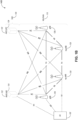
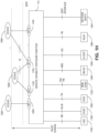
- FIG. 1A illustrates an architecture of a network in accordance with some aspects.
- the network 140A is shown to include a user equipment (UE) 101 and a UE 102.
- the UEs 101 and 102 are illustrated as smartphones (e.g., handheld touchscreen mobile computing devices connectable to one or more cellular networks), but may also comprise any mobile or non-mobile computing device, such as Personal Data Assistants (PDAs), pagers, laptop computers, desktop computers, wireless handsets, drones, or any other computing device including a wired and/or wireless communications interface.
- PDAs Personal Data Assistants
- pagers pagers
- laptop computers desktop computers
- wireless handsets wireless handsets
- drones or any other computing device including a wired and/or wireless communications interface.
- any of the UEs 101 and 102 can comprise an Internet-of-Things (IoT) UE or a Cellular IoT (CIoT) UE, which can comprise a network access layer designed for low-p ower loT applications utilizing short-lived UE connections.
- IoT Internet-of-Things
- CIoT Cellular IoT
- any of the UEs 101 and 102 can include a narrowband (NB) IoT UE (e.g., such as an enhanced NB-IoT (eNB-IoT) UE and Further Enhanced (FeNB-IoT) UE).
- NB narrowband
- eNB-IoT enhanced NB-IoT
- FeNB-IoT Further Enhanced
- An IoT UE can utilize technologies such as machine-to-machine (M2M) or machine-type communications (MTC) for exchanging data with an MTC server or device via a public land mobile network (PLMN), Proximity -Based Service (ProSe) or device-to-device (D2D) communication, sensor networks, or IoT networks.
- M2M machine-to-machine
- MTC machine-type communications
- PLMN public land mobile network
- D2D device-to-device
- the M 2M or MTC exchange of data may be a machine-initiated exchange of data.
- An IoT network includes interconnecting IoT UEs, which may include uniquely identifiable embedded computing devices (within the Internet infrastructure), with short-lived connections.
- the IoT UEs may execute background applications (e.g., keep-alive messages, status updates, etc.) to facilitate the connections of the IoT network.
- NB-IoT devices can be configured to operate in a single physical resource block (PRB) and may be instructed to retune two different PRBs within the system bandwidth.
- an eNB-IoT UE can be configured to acquire sy stem information in one PRB, and then it can retune to a different PRB to receive or transmit data.
- any of the UEs 101 and 102 can include enhanced MTC (eM T C) UEs or further enhanced MTC (FeMTC) UEs.
- eM T C enhanced MTC
- FeMTC enhanced MTC
- the UEs 101 and 102 may be configured to connect, e.g., communicatively couple, with a radio access network (RAN) 110.
- the RAN 110 may be, for example, an Evolved Universal Mobile Telecommunications System (UMTS) Terrestrial Radio Access Network (E-UTRAN), a NextGen RAN (NG RAN), or some other typeofRAN.
- UMTS Evolved Universal Mobile Telecommunications System
- E-UTRAN Evolved Universal Mobile Telecommunications System
- NG RAN NextGen RAN
- the UEs 101 and 102 utilize connections 103 and 104, respectively, each of which comprises a physical communications interface or layer (discussed in further detail below); in this example, the connections 103 and 104 are illustrated as an air interface to enable communicative coupling and can be consistent with cellular communications protocols, such as a Global System for Mobile Communications (GSM) protocol, a code-division multiple access (CDMA) network protocol, a Push-to-Talk (PTT) protocol, a PTT over Cellular (POC) protocol, a Universal Mobile Telecommunications System (UMTS) protocol, a 3GPP Long Term Evolution (LTE) protocol, a fifth generation (5G) protocol, a New Radio (NR) protocol, and the like.
- GSM Global System for Mobile Communications
- CDMA code-division multiple access
- PTT Push-to-Talk
- POC PTT over Cellular
- UMTS Universal Mobile Telecommunications System
- LTE Long Term Evolution
- 5G fifth generation
- NR New Radio
- the network 140A can include a core network (CN) 120.
- CN core network
- Various aspects ofNG RAN and NG Core are discussed herein in reference to, e.g., FIG. 1B , FIG. 1C , FIG. 1D , FIG. 1E , FIG. 1F , and FIG. 1G .
- the UEs 101 and 102 may further directly exchange communication data via a ProSe interface 105.
- the ProSe interface 105 may alternatively be referred to as a sidelink interface comprising one or more logical channels, including but not limited to a Physical Sidelink Control Channel (PSCCH), a Physical Sidelink Shared Channel (PSSCH), a Physical Sidelink Discovery Channel (PSDCH), and a Physical Sidelink Broadcast Channel (PSBCH).
- PSCCH Physical Sidelink Control Channel
- PSSCH Physical Sidelink Shared Channel
- PSDCH Physical Sidelink Discovery Channel
- PSBCH Physical Sidelink Broadcast Channel
- the UE 102 is shown to be configured to access an access point (AP) 106 via connection 107.
- the connection 107 can comprise a local wireless connection, such as, for example, a connection consistent with any IEEE 802.11 protocol, according to which the AP 106 can comprise a wireless fidelity (WiFi ® ) router.
- WiFi ® wireless fidelity
- the AP 106 is shown to be connected to the Internet without connecting to the core network of the wireless system (described in further detail below).
- the RAN 110 can include one or more access nodes that enable the connections 103 and 104.
- These access nodes can be referred to as base stations (BSs), NodeBs, evolved NodeBs (eNBs), Next Generation NodeBs (gNBs), RAN nodes, and the like, and can comprise ground stations (e.g., terrestrial access points) or satellite stations providing coverage within a geographic area (e.g., a cell).
- the communication nodes 111 and 112 can be transmission/reception points (TRPs). In instances when the communication nodes 111 and 112 are NodeBs (e.g., eNBs or gNBs), one or more TRPs can function within the communication cell of the NodeBs.
- the RAN 110 may include one or more RAN nodes for providing macrocells, e.g, macro RAN node 111, and one or more RAN nodes for providing femtocells or picocells (e.g., cells having smaller coverage areas, smaller user capacity, or higher bandwidth compared to macrocells), e.g., low power (LP) RAN node 112.
- macro RAN node 111 e.g., macro RAN node 111
- femtocells or picocells e.g., cells having smaller coverage areas, smaller user capacity, or higher bandwidth compared to macrocells
- LP low power
- any of the RAN nodes 111 and 112 can terminate the air interface protocol and can be the first point of contact for the UEs 101 and 102.
- any of the RAN nodes 111 and 112 can fulfill various logical functions for the RAN 110 including, but not limited to, radio network controller (RNC) functions such as radio bearer management, uplink and downlink dynamic radio resource management and data packet scheduling and mobility management.
- RNC radio network controller
- any of the nodes 111 and/or 112 can be a new generation node-B (gNB), an evolved node-B (eNB), or another type of RAN node.
- gNB new generation node-B
- eNB evolved node-B
- the UEs 101 and 102 can be configured to communicate using Orthogonal Frequency-Division Multiplexing (OFDM) communication signals with each other or with any of the RAN nodes 111 and 112 over a multicarrier communication channel in accordance various communication techniques, such as, but not limited to, an Orthogonal Frequency-Division Multiple Access (OFDMA) communication technique (e.g., for downlink communications) or a Single Carrier Frequency Division Multiple Access (SC-FDMA) communication technique (e.g., for uplink and ProSe for sidelink communications), although such aspects are not required.
- OFDM signals can comprise a plurality of orthogonal subcarriers.
- a downlink resource grid can be used for downlink transmissions from any of the RAN nodes 111 and 112 to the UEs 101 and 102, while uplink transmissions can utilize similar techniques.
- the grid can be a time-frequency grid, called a resource grid or time-frequency resource grid, which is the physical resource in the downlink in each slot.
- a time-frequency plane representation may be used for OFDM systems, which makes it applicable for radio resource allocation.
- Each column and each row of the resource grid may correspond to one OFDM symbol and one OFDM subcarrier, respectively.
- the duration of the resource grid in the time domain may correspond to one slot in a radio frame.
- the smallest time-frequency unit in a resource grid may be denoted as a resource element.
- Each resource grid may comprise a number of resource blocks, which describe mapping of certain physical channels to resource elements.
- Each resource block may comprise a collection of resource elements; in the frequency domain, this may, in some aspects, represent the smallest quantity of resources that currently can be allocated. There may be several different physical downlink channels that are conveyed using such resource blocks.
- the physical downlink shared channel may carry user data and higher-layer signaling to the UEs 101 and 102.
- the physical downlink control channel (PDCCH) may carry information about the transport format and resource allocations related to the PDSCH channel, among other things. It may also inform the UEs101 and 102 about the transport format, resource allocation, and H-ARQ (Hybrid Automatic Repeat Request) information related to the uplink shared channel.
- downlink scheduling (assigning control and shared channel resource blocks to the UE 102 within a cell) may be performed at any of the RAN nodes 111 and 112 based on channel quality information fed back from any of the UEs 101 and 102.
- the downlink resource assignment information may be sent on the PDCCH used for (e.g., assigned to) each of the UEs 101 and 102.
- the PDCCH may use control channel elements (CCEs) to convey the control information.
- CCEs control channel elements
- the PDCCH complex-valued symbols may first be organized into quadruplets, which may then be permuted using a sub-block interleaver for rate matching
- Each PDCCH may be transmitted using one or more of these CCEs, where each CCE may correspond to nine sets of four physical resource elements known as resource element groups (REGs).
- RAGs resource element groups
- QPSK Quadrature Phase Shift Keying
- the PDCCH can be transmitted using one or more CCEs, depending on the size of the downlink control information (DCI) and the channel condition.
- DCI downlink control information
- There can be four or more different PDCCH formats defined in LTE with different numbers of CCEs (e.g., aggregation level, L 1, 2, 4, or 8).
- Some aspects may use concepts for resource allocation for control channel information that are an extension of the above-described concepts.
- some aspects may utilize an enhanced physical downlink control channel (EPDCCH) that uses PDSCH resources for control information transmission.
- the EPDCCH may be transmitted using one or more enhanced control channel elements (ECCEs). Similar to above, each ECCE may correspond to nine sets of four physical resource elements known as an enhanced resource element groups (EREGs). An ECCE may have other numbers of EREGs according to some arrangements.
- EPCCH enhanced physical downlink control channel
- ECCEs enhanced control channel elements
- each ECCE may correspond to nine sets of four physical resource elements known as an enhanced resource element groups (EREGs).
- EREGs enhanced resource element groups
- An ECCE may have other numbers of EREGs according to some arrangements.
- the RAN 110 is shown to be communicatively coupled to a core network (CN) 120 via an S1 interface 113.
- theCN 120 may be an evolved packet core (EPC) network, a NextGen Packet Core (NPC) network, or some other type of CN (e.g., as illustrated in reference to FIGS. 1B-1I ).
- EPC evolved packet core
- NPC NextGen Packet Core
- the S1 interface 113 is split into two parts: the S1-U interface 114, which carries traffic data between the RAN nodes 111 and 112 and the serving gateway (S-GW) 122, and the S1-mobility management entity (MME) interface 115, which is a signaling interface between the RAN nodes 111 and 112 and MMEs 121.
- S-GW serving gateway
- MME S1-mobility management entity
- the CN 120 comprises the MMEs 121, the S-GW 122, the Packet Data Network (PDN) Gateway (P-GW) 123, and a home subscriber server (HSS) 124.
- the MMEs 121 may be similar in function to the control plane of legacy Serving General Packet Radio Service (GPRS) Support Nodes (SGSN).
- the MMEs 121 may manage mobility aspects in access such as gateway selection and tracking area list management.
- the HSS 124 may comprise a database for network users, including subscription-related information to support the network entities' handling of communication sessions.
- the CN 120 may comprise one or several HSSs 124, depending on the number of mobile subscribers, on the capacity of the equipment, on the organization of the network, etc.
- the HSS 124 can provide support for routing/roaming, authentication, authorization, naming/addressing resolution, location dependencies, etc.
- the S-GW 122 may terminate the S1 interface 113 towards the RAN 110, and routes data packets between the RAN 110 and the CN 120.
- the S-GW 122 may be a local mobility anchor point for inter-RAN node handovers and also may provide an anchor for inter-3GPP mobility. Other responsibilities of the S-GW 122 may include lawful intercept, charging and some policy enforcement.
- the P-GW 123 may terminate a SGi interface toward a PDN.
- the P-GW 123 may route data packets between the EPC network 120 and external networks such as a network including the application server 184 (alternatively referred to as application function (AF)) via an Internet Protocol (IP) interface 125.
- TheP-GW 123 can also communicate data to other external networks 131A, which can include the Internet, IP multimedia subsystem (IPS) network, and other networks.
- the application server 184 may be an element offering applications that use IP bearer resources with the core network (e.g., UMTS Packet Services (PS) domain, LTE PS data services, etc.).
- PS UMTS Packet Services
- the P-GW 123 is shown to be communicatively coup led to an application server 184 via an IP interface 125.
- the application server 184 can also be configured to support one or more communication services (e.g., Voice-over-Internet Protocol (VoIP) sessions, PTT sessions, group communication sessions, social networking services, etc.) for theUEs 101 and 102 via the CN 120.
- VoIP Voice-over-Internet Protocol
- the P-GW 123 may further be a node for policy enforcement and charging data collection.
- Policy and Charging Rules Function (PCRF) 126 is the policy and charging control element of the CN 120.
- PCRF Policy and Charging Rules Function
- HPLMN Home Public Land Mobile Network
- IP-CAN Internet Protocol Connectivity Access Network
- H-PCRF Home PCRF
- V-PCRF Visited PCRF
- the PCRF 126 may be communicatively coupled to the application server 184 via the P-GW 123.
- the application server 184 may signal the PCRF 126 to indicate a new service flow and select the appropriate Quality of Service (QoS) and charging parameters.
- the PCRF 126 may provision this rule into a Policy and Charging Enforcement Function (PCEF) (not shown) with the appropriate traffic flow template (TFT) and QoS class of identifier (QCI), which commences the QoS and charging as specified by the application server 184.
- PCEF Policy and Charging Enforcement Function
- TFT traffic flow template
- QCI QoS class of identifier
- any of the nodes 111 or 112 can be configured to communicate to the UEs 101, 102 (e.g., dynamically) an antenna panel selection and a receive (Rx) beam selection that can be used by the UE for data reception on a physical downlink shared channel (PDSCH) as well as for channel state information reference signal (CSI-RS) measurements and channel state information (CSI) calculation.
- PDSCH physical downlink shared channel
- CSI-RS channel state information reference signal
- CSI channel state information
- any of the nodes 111 or 112 can be configured to communicate to the UEs 101, 102 (e.g., dynamically) an antenna panel selection and a transmit (Tx) beam selection that can be used by the UE for data transmission on a physical uplink shared channel (PUSCH) as well as for sounding reference signal (SRS) transmission.
- Tx transmit
- PUSCH physical uplink shared channel
- SRS sounding reference signal
- the communication network 140A can be an IoT network.
- One of the current enablers of IoT is the narrowband-IoT (NB-IoT).
- NB-IoT has objectives such as coverage extension, UE complexity reduction, long battery lifetime, and backward compatibility with the LTE network.
- NB-IoT aims to offer deployment flexibility allowing an operator to introduce NB-IoT using a small portion of its existing available spectrum, and operate in one of the following three modalities: (a) standalone deployment (the network operates in re-farmed GSM spectrum); (b) in-band deployment (the network operates within the LTE channel); and (c) guard-band deployment (the network operates in the guard band of legacy LTE channels).
- NB-IoT further enhanced NB-IoT
- support forNB-IoT in small cells can be provided (e.g, in microcell, picocell or femtocell deployments).
- NB-IoT sy stems face for small cell support is the UL/DL link imbalance, where for small cells the base stations have lower power available compared to macro-cells, and, consequently, the DL coverage can be affected and/or reduced.
- some NB-IoT UEs can be configured to transmit at maximum power if repetitions are used for UL transmission. This may result in large inter-cell interference in dense small cell deployments.
- Techniques disclosed herein can be used in connection with FeNB-IoT communications and, more specifically, mitigating the inter-cell interference effect for NPRACH and NPUSCH in small cell environments as well as improving downlink coverage when transmission power of a small cell base station is smaller than base station transmission p ower in a microcell.
- FIG. 1B is a simplified diagram of a next generation (NG) system architecture 140B in accordance with some aspects.
- the NG system architecture 140B includes RAN 110 and a 5G network core (5GC) 120.
- the NG-RAN 110 can include a plurality of nodes, such as gNBs 128 and NG-eNBs 130.
- the gNBs 128 and the NG-eNBs 130 can be communicatively coupled to the UE 102 via, e.g., an N1 interface.
- the core network 120 can include an access and mobility management function (AMF) 132 and/or a user plane function (UPF) 134.
- the AMF 132 and the UPF 134 can be communicatively coupled to thegNBs 128 and the NG-eNBs 130 via NG interfaces. More specifically, in some aspects, the gNBs 128 and theNG-eNBs 130 can be connected to the AMF 132 by NG-C interfaces, and to the UPF 134 by NG-U interfaces.
- the gNBs 128 and the NG-eNBs 130 can be coupled to each other via Xn interfaces.
- a gNB 128 can include a node providing new radio (NR) user plane and control plane protocol termination towards the UE, and is connected via the NG interface to the 5GC 120.
- an NG-eNB 130 can include anode providing evolved universal terrestrial radio access (E-UTRA) user plane and control plane protocol terminations towards the UE, and is connected via the NG interface to the 5GC 120.
- E-UTRA evolved universal terrestrial radio access
- each of the gNBs 128 and the NG-eNBs 130 can be implemented as a base station, a mobile edge server, a small cell, a home eNB, and so forth.
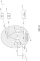
- FIG. 1C illustrates an example MulteFire Neutral Host Network (NHN) 5G architecture 140C in accordance with some aspects.
- the MulteFire 5G architecture 140C can include the UE 102, NG-RAN 110, and core network 120.
- the NG-RAN 110 can be a MulteFireNG-RAN (MF NG-RAN), and the core network 120 can be a MulteFire5G neutral host network (NHN).
- MF NG-RAN MulteFireNG-RAN
- NHS MulteFire5G neutral host network
- the MF NHN 120 can include a neutral host AMF (NH AMF) 132, a NH SMF 136, a NH UPF 134, and a local AAA proxy 151C.
- the AAA proxy 151C can provide connection to a 3GPP AAA server 155C and a participating service provider AAA (PSP AAA) server 153C.
- the NH-UPF 134 can provide a connection to a data network 157C.
- the MF NG-RAN 120 can provide similar functionalities as an NG-RAN op erating under a 3GPP specification.
- the NH-AM F 132 can be configured to provide similar functionality as a AMF in a 3GPP 5G core network (e.g., as described in reference to FIG. 1D ).
- the NH-SMF 136 can be configured to provide similar functionality as a SMF in a 3GPP 5G core network (e.g., as described in reference to FIG. 1D ).
- TheNH-UPF 134 can be configured to provide similar functionality as a UPF in a 3GPP 5Gcore network (e.g., as described in reference to FIG. 1D ).
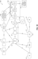
- FIG. 1D illustrates a functional split between NG-RAN and the 5G Core (5GC) in accordance with some aspects.
- 5GC 5G Core
- FIG. 1D there is illustrated a more detailed diagram of the functionalities that can be performed by the gNBs 128 and the NG-eNBs 130 within the NG-RAN 110, as well as the AMF 132, the UPF 134, and the SMF 136 within the 5GC 120.
- the 5GC 120 can provide access to the Internet 138 to one or more devices via the NG-RAN 110.
- the gNBs 128 and the NG-eNBs 130 can be configured to host the following functions: functions for Radio Resource Management (e.g., inter-cell radio resource management 129A, radio bearer control 129B, connection mobility control 129C, radio admission control 129D, dynamic allocation of resources to UEs in both uplink and downlink (scheduling) 129F); IP header compression, encryption and integrity protection of data; selection of an AMF at UE attachment when no routing to an AMF can be determined from the information provided by theUE; routing of User Plane data towards UPF(s); routing of Control Plane information towards AMF; connection setup and release; scheduling and transmission of paging messages (originated from the AMF); scheduling and transmission of sy stem broadcast information (originated from the AMF or Operation and Maintenance); measurement and measurement reporting configuration for mobility and scheduling 129E; transport level packet marking in the uplink; session management; support of network slicing; QoS flow management and mappingto data radio bearers; support of UEs in
- the AMF 132 can be configured to host the following functions, for example: NAS signaling termination; NAS signaling security 133A; access stratum (AS) security control; inter core network (CN) node signaling for mobility between 3GPP access networks; idle state/ mode mobility handling 133B, including mobile device, such as a UE reachability (e.g., control and execution of paging retransmission); registration area management; sup port of intra-sy stem and inter-sy stem mobility; access authentication; access authorization including check of roaming rights; mobility management control (subscription and policies); support of network slicing; and/or SMF selection, among other functions.
- NAS signaling termination NAS signaling security 133A
- AS access stratum
- CN inter core network
- the UPF 134 can be configured to host the following functions, for example: mobility anchoring 135A (e.g., anchor point for Intra-/Inter-RAT mobility); packet data unit (PDU) handling 135B (e.g., external PDU session point of interconnect to data network); packet routing and forwarding; packet inspection and user plane part of policy rule enforcement; traffic usage reporting uplink classifier to support routingtraffic flows to a data network; branching point to support multi-homed PDU session; QoS handling for user plane, e.g., packet filtering, gating UL/DL rate enforcement; uplink traffic verification (SDF to QoS flow mapping); and/or downlink packet buffering and downlink data notification triggering, among other functions.
- mobility anchoring 135A e.g., anchor point for Intra-/Inter-RAT mobility
- PDU packet data unit
- packet routing and forwarding e.g., packet inspection and user plane part of policy rule enforcement
- traffic usage reporting uplink classifier to support routingtraffic flows to a
- the Session Management function (SMF) 136 can be configured to host the following functions, for example: session management; UE IP address allocation and management 137A; selection and control of user plane function (UPF); PDU session control 137B, including configuring traffic steering at UPF 134 to route traffic to proper destination; control part of policy enforcement and QoS; and/or downlink data notification, among other functions.
- SMF Session Management function
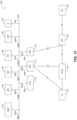
- FIG. 1E and FIG. 1F illustrate a non-roaming 5G system architecture in accordance with some aspects.
- a 5G system architecture 140E in a reference point representation. More specifically, UE 102 can be in communication with RAN 110 as well as one or more other 5G core (5GC) network entities.
- 5GC 5G core
- the 5G system architecture 140E includes a plurality of network functions (NFs), such as access and mobility management function (AMF) 132, session management function (SMF) 136, policy control function (PCF) 148, application function (AF) 150, user plane function (UPF) 134, network slice selection function (NSSF) 142, authentication server function (AUSF) 144, and unified data management (UDM)/home subscriber server (HSS) 146.
- the UPF 134 can provide a connection to a data network (DN) 152, which can include, for example, operator services, Internet access, or third-party services.
- DN data network
- the AMF can be used to manage access control and mobility, and can also include network slice selection functionality.
- the SMF can be configured to set up and manage various sessions according to a network policy.
- the UPF can be deployed in one or more configurations according to a desired service type.
- the PCF can be configured to provide a policy framework using network slicing, mobility management, and roaming (similar to PCRF in a 4G communication system).
- the UDM can be configured to store subscriber profiles and data (similar to an HSS in a 4G communication sy stem).
- the 5G sy stem architecture 140E includes an IP multimedia subsy stem (IMS) 168E as well as a plurality of IP multimedia core network subsystem entities, such as call session control functions (CSCFs). More specifically, the IMS 168E includes a CSCF, which can act as a proxy CSCF (P-CSCF) 162E, a serving CSCF (S-CSCF) 164E, an emergency CSCF (E-CSCF) (not illustrated in FIG. 1E ), and/or interrogating CSCF (I-CSCF) 166E.
- P-CSCF 162E can be configured to be the first contact point for the UE 102 within the IM subsystem (IMS) 168E.
- the S-CSCF 164E can be configured to handle the session states in the network, and the E-CSCF can be configured to handle certain aspects of emergency sessions such as routing an emergency request to the correct emergency center or PSAP.
- the I-CSCF 166E can be configured to function as the contact point within an operator's network for all IMS connections destined to a subscriber of that network op erator, or a roaming subscriber currently located within that network operator's service area.
- the I-CSCF 166E can be connected to another IP multimedia network 170E, e.g. an IMS operated by a different network operator.
- the LDM/HSS 146 can be coupled to an application server 160E, which can include a telephony application server (TAS) or another application server (AS).
- the AS 160E can be coupled to the IM S 168E via the S-CSCF 164E and/or theI-CSCF 166E.
- the 5G sy stem architecture 140E can use a unified access barring mechanism using one or more of the techniques described herein, which access barring mechanism can be applicable for all RRC states of the UE 102, such as RRC IDLE, RRC_CONNECTED, and RRC INACTIVE states.
- the 5G sy stem architecture 140E can be configured to use 5G access control mechanism techniques described herein, based on access categories that can be categorized by a minimum default set of access categories, which are common across all networks.
- This functionality can allow the public land mobile network PLMN, such as a visited PLMN (VPLMN) to protect the network against different types of registration attempts, enable acceptable service for the roaming subscriber and enable the VPLMN to control access attempts aiming at receiving certain basic services. It also provides more options and flexibility to individual operators by providing a set of access categories, which can be configured and used in operator specific ways.
- PLMN public land mobile network
- VPN visited PLMN
- System architecture 140F can be substantially similar to (or the same as) system architecture 140E.
- system architecture 140F can also include a network exposure function (NEF) 154 and a network repository function (NRF) 156.
- NEF network exposure function
- NRF network repository function
- 5G system architectures can be service-based and interaction between network functions can be represented by corresponding point-to-p oint reference points Ni (as illustrated in FIG. 1E ) or as service-based interfaces (as illustrated in FIG. 1F ).
- FIG. 1E illustrates the following reference points: N1 (between the UE 102 and the AMF 132), N2 (between the RAN 110 and the AMF 132), N3 (between the RAN 110 and the UPF 134), N4 (between the SMF 136 and theUPF 134), N5 (between the PCF 148 and the AF 150), N6 (between the UPF 134 and the DN 152), N7 (between the SMF 136 and the PCF 148), N8 (between theUDM 146 and theAMF 132), N9 (between two UPFs 134), N10 (between the UDM 146 and the SMF 136), N11 (between theAMF 132 and the SMF 136), N12 (between the AliSF 144 and the AM F 132), N13 (between the AUSF 144 and the UDM 146), N14 (between two AMFs 132), N15 (between the PCF 148 and theAMF
- service-based representations can be used to represent network functions within the control plane that enable other authorized network functions to access their services.
- 5G system architecture 140F can include the following service-based interfaces: Namf 158H (a service-based interface exhibited by the AMF 132), Nsmf 158I (a service-based interface exhibited by the SMF 136), Nnef 158B (a service-based interface exhibited by the NEF 154), Npcf 158D (a service-based interface exhibited by the PCF 148), a Nudm 158E (a service-based interface exhibited by the UDM 146), Naf 158F (a service-based interface exhibited by the AF 150), Nnrf 158C (a service-based interface exhibited by the NRF 156), Nnssf 158A (a service-based interface exhibited by the NSSF 142), Nausf 158G (a service-based interface exhibited by the AUSF 144
- FIG. 1G illustrates an example CIoT network architecture in accordance with some aspects.
- the CIoT architecture 140G can include the UE 102 and the RAN 110 coupled to a plurality of core network entities.
- the UE 102 can be machine-type communication (MTC)UE.
- MTC machine-type communication
- the CIoT network architecture 140G can further include a mobile services switching center (MSC) 160, MME 121, a serving GPRS support note(SGSN) 162, a S-GW 122, an IP-Short-Message-Gateway (IP-SM-GW) 164, a Short Message Service Service Center (SMS-SC)/gateway mobile service center (GM SC)/Interworking MSC (IWM SC) 166, MTC interworking function (MTC-IWF) 170, a Service Capability Exposure Function (SCEF) 172, a gateway GPRS support node (GGSN)/Packet-GW (P-GW) 174, a charging data function (CDF)/charging gateway function (CGF) 176, a home subscriber server (HSS)/a home location register (HLR) 177, short message entities (SME) 168, MTC authorization, authentication, and accounting (MTC AAA) server 178, a service capability server (SCS) 180, and application servers (AS)
- the SCEF 172 can be configured to securely expose services and capabilities provided by various 3GPP network interfaces.
- the SCEF 172 can also provide means for the discovery of the exposed services and capabilities, as well as access to network capabilities through various network application programming interfaces (e.g., API interfaces to the SCS 180).
- FIG. 1G further illustrates various reference points between different servers, functions, or communication nodes of the CIoT network architecture 140G.
- Some example reference points related toMTC-IWF 170 and SCEF 172 include the following: Tsms (a reference point used by an entity outside the 3GPP network to communicate with UEs used for MTC via SMS), Tsp (a reference point used by a SCS to communicate with theMTC-IWF related control plane signaling), T4 (a reference point used between MTC-IWF 170 and the SMS-SC 166 in the HPLMN), T6a (a reference point used between SCEF 172 and serving MVIE 121), T6b (a reference point used between SCEF 172 and serving SGSN 162), T8 (a reference point used between the SCEF 172 and the SCS/AS 180/182), S6m (a reference point used by MTC-IWF 170 to interrogate HSS/HLR 177), S6n (a reference point used by MTC-AAA server
- the CIoT UE 102 can be configured to communicate with one or more entities within the CIoT architecture 140G via the RAN 110 according to a Non-Access Stratum (NAS) protocol, and using one or more reference points, such as a narrowband air interface, for example, based on one or more communication technologies, such as Orthogonal Frequency-Division Multiplexing (OFDM) technology.
- NAS Non-Access Stratum
- OFDM Orthogonal Frequency-Division Multiplexing
- the term "CIoT UE” refers to a UE capable of CIoT optimizations, as part of a CIoT communications architecture.
- the NAS protocol can support a set of NAS messages for communication between the CIoT UE 102 and an Evolved Packet System (EPS) Mobile Management Entity (MME) 121 and SGSN 162.
- EPS Evolved Packet System
- MME Mobile Management Entity
- the CIoT network architecture 140F can include a packet data network, an operator network, or a cloud service network, having for example, among other things, a Service Capability Server (SCS) 180, an Application Server (AS) 182, or one or more other external servers or network components.
- SCS Service Capability Server
- AS Application Server
- the RAN 110 can be coupled to the HSS/HLR servers 177 and the AAA servers 178 using one or more reference points including for example, an air interface based on an S6a reference point, and configured to authenticate/authorize CIoT UE 102 to access the CloT network.
- the RAN 110 can be coupled to the CIoT network architecture 140G using one or more other reference points including for example, an air interface corresponding to an SGi/Gi interface for 3GPP accesses.
- the RAN 110 can be coupled to the SCEF 172 using for example, an air interface based on a T6a/T6b reference point, for service capability exposure.
- the SCEF 172 may act as an API GW towards a third-party application server such as AS 182.
- the SCEF 172 can be coupled to the HSS/HLR 177 and MTC AAA 178 servers using an S6t reference point, and can further expose an Application Programming Interface to network capabilities.
- one or more of the CloT devices disclosed herein can include one or more other non-CIoT devices, or non-CIoT devices acting as CIoT devices, or having functions of a CIoT device.
- the CIoT UE 102 can include a smart phone, a tablet computer, or one or more other electronic device acting as a CIoT device for a specific function, while having other additional functionality.
- the RAN 110 can include a CloT enhanced Node B (CIoT eNB) 111 communicatively coupled to the CloT Access Network Gateway (CIoT GW) 195.
- the RAN 110 can include multiple base stations (e.g., CIoT eNBs) connected to the CIoT GW 195, which can include MSC 160, MME 121, SGSN 162, and/or S-GW 122.
- the internal architecture of RAN 110 and CloT GW 195 may be left to the implementation and need not be standardized.
- circuitry may refer to, be part of, or include an Application Specific Integrated Circuit (ASIC) or other special purpose circuit, an electronic circuit, a processor (shared, dedicated, or group), or memory (shared, dedicated, or group) executing one or more software or firmware programs, a combinational logic circuit, or other suitable hardware components that provide the described functionality.
- ASIC Application Specific Integrated Circuit
- the circuitry may be implemented in, or functions associated with the circuitry may be implemented by, one or more software or firmware modules.
- circuitry may include logic, at least partially operable in hardware.
- circuitry as well as modules disclosed herein may be implemented in combinations of hardware, software and/or firmware.
- functionality associated with a circuitry can be distributed across more than one piece of hardware or software/firmware module.
- modules may include logic, at least partially operable in hardware. Aspects described herein may be implemented into a sy stem using any suitably configured hardware or software.
- FIG. 1H illustrates an example Service Capability Exposure Function (SCEF) in accordance with some aspects.
- SCEF Service Capability Exposure Function
- the SCEF 172 can be configured to expose services and capabilities provided by 3GPP network interfaces to external third party service provider servers hosting various applications.
- a 3GPP network such as the CIoT architecture 140G, can expose the following services and capabilities: a home subscriber server (HSS) 116H, a policy and charging rules function (PCRF) 118H, a packet flow description function (PFDF) 120H, a MME/SGSN 122H, a broadcast multicast service center (BM-SC) 124H, a serving call server control function (S-CSCF) 126H, a RAN congestion awareness function (RCAF) 128H, and one or more other network entities 130H.
- the above-mentioned services and capabilities of a 3GPP network can communicate with the SCEF 172 via one or more interfaces as illustrated in FIG. 1H .
- the SCEF 172 can be configured to expose the 3GPP network services and capabilities to one or more applications running on one or more service capability server (SCS)/application server (AS), such as SCS/AS 102H, 104H, ..., 106H.
- SCS service capability server
- AS application server
- Each of the SCS/AG 102H-106H can communicate with the SCEF 172 via application programming interfaces (APIs) 108H, 110H, 112H, ..., 114H, as seen in FIG. 1H .
- APIs application programming interfaces
- FIG. 1I illustrates an example roaming architecture for SCEF in accordance with some aspects.
- the SCEF 172 can be located in HPLMN 110I and can be configured to expose 3GPP network services and capabilities, such as 102I, ..., 104I.
- 3GPP network services and capabilities such as 106I, ..., 108I, can be located within VPLMN 112I.
- the 3GPP network services and capabilities within the VPLMN 112I can be exposed to the SCEF 172 via an interworking SCEF (IWK-SCEF) 197 within the VPLMN 1121.
- IWK-SCEF interworking SCEF
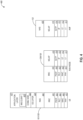
- FIG. 2 illustrates example components of a device 200 in accordance with some aspects.
- the device 200 may include application circuitry 202, baseband circuitry 204, Radio Frequency (RF) circuitry 206, front-end module (FEM) circuitry 208, one or more antennas 210, and power management circuitry (PMC) 212 coupled together at least as shown.
- the components of the illustrated device 200 may be included in a UE or a RAN node.
- the device 200 may include fewer elements (e.g., a RAN node may not utilize application circuitry 202, and instead include a processor/controller to process IP data received from an EPC).
- the device 200 may include additional elements such as, for example, memory/storage, display, camera, sensor, and/or input/output (I/O) interface elements.
- the components described below may be included in more than one device (e.g., said circuitries may be separately included in more than one device for Cloud-RAN (C-RAN) implementations).
- C-RAN Cloud-RAN
- the application circuitry 202 may include one or more application processors.
- the application circuitry 202 may include circuitry such as, but not limited to, one or more single-core or multi-core processors.
- the processor(s) may include any combination of general-purpose processors, special-purpose processors, and dedicated processors (e.g., graphics processors, application processors, etc.).
- Theprocessors may be coupled with, and/or may include, memory/storage and may be configured to execute instructions stored in the memory/storage to enable various applications or operating sy stems to run on the device 200.
- processors of application circuitry 202 may process IP data packets received from an EPC.
- the baseband circuitry 204 may include circuitry such as, but not limited to, one or more single-core or multi-core processors.
- the baseband circuitry 204 may include one or more baseband processors or control logic to process baseband signals received from a receive signal path of the RF circuitry 206 and to generate baseband signals for a transmit signal path of the RF circuitry 206.
- Baseband processing circuity 204 may interface with the application circuitry 202 for generation and processing of the baseband signals and for controlling operations of the RF circuitry 206.
- the baseband circuitry 204 may include a third generation (3G) baseband processor 204A, a fourth generation (4G) baseband processor204B, a fifth generation (5G) baseband processor 204C, or other baseband processor(s) 204D for other existing generations, generations in development or to be developed in the future (e.g., second generation (2G), sixth generation (6G), etc.).
- the baseband circuitry 204 e.g., one or more of baseband processors 204A-D
- baseband processors 204A-D may be included in modules stored in the memory 204G and executed via a Central Processing Unit (CPU) 204E.
- the radio control functions may include, but are not limited to, signal modulation/demodulation, encoding/decoding, radio frequency shifting, etc.
- modulation/demodulation circuitry of the baseband circuitry 204 may include Fast-Fourier Transform (FFT), precoding or constellation mapping/de-mapping functionality.
- encoding/decoding circuitry of the baseband circuitry 204 may include convolution, tail-biting convolution, turbo, Viterbi, or Low-Density Parity Check (LDPC) encoder/decoder functionality. Aspects of modulation/demodulation and encoder/decoder functionality are not limited to these examples and may include other suitable functionality in other aspects.
- FFT Fast-Fourier Transform
- encoding/decoding circuitry of the baseband circuitry 204 may include convolution, tail-biting convolution, turbo, Vit
- the baseband circuitry 204 may include one or more audio digital signal processor(s) (DSP) 204F.
- the audio DSP(s) 204F may be include elements for compression/decompression and echo cancellation and may include other suitable processing elements in other aspects.
- Components of the baseband circuitry 204 may be suitably combined in a single chip, a single chip set, or disposed on a same circuit board in some aspects.
- some or all of the constituent components of the baseband circuitry 204 and the application circuitry 202 may be implemented together such as, for example, on a system on a chip (SOC).
- SOC system on a chip
- the baseband circuitry 204 may provide for communication compatible with one or more radio technologies.
- the baseband circuitry 204 may support communication with an evolved universal terrestrial radio access network (EUTRAN) or other wireless metropolitan area networks (WM AN), a wireless local area network (WLAN), and/or a wireless personal area network (WPAN).
- EUTRAN evolved universal terrestrial radio access network
- WM AN wireless metropolitan area networks
- WLAN wireless local area network
- WPAN wireless personal area network
- Baseband circuitry 204 configured to support radio communications of more than one wireless protocol may be referred to as multi-mode baseband circuitry, in some aspects.
- RF circuitry 206 may enable communication with wireless networks using modulated electromagnetic radiation through a non-solid medium.
- the RF circuitry 206 may include switches, filters, amplifiers, etc. to facilitate the communication with the wireless network.
- RF circuitry 206 may include a receive signal path which may include circuitry to down-convert RF signals received from the FEM circuitry 208 and provide baseband signals to the baseband circuitry 204.
- RF circuitry 206 may also include a transmit signal path which may include circuitry to up-convert baseband signals provided by the baseband circuitry 204 and provide RF output signals to the FEM circuitry 208 for transmission.
- the receive signal path of the RF circuitry 206 may include a mixer 206A, an amplifier 206B, and a filter 206C.
- the transmit signal path of the RF circuitry 206 may include a filter 206C and a mixer 206A.
- RF circuitry 206 may also include a synthesizer206D for synthesizing a frequency for use by the mixer 206A of the receive signal path and the transmit signal path.
- the mixer 206A of the receive signal path may be configured to down-convert RF signals received from the FEM circuitry 208 based on the synthesized frequency provided by synthesizer 206D.
- the amplifier 206B may be configured to amplify the down-converted signals and the filter 206C may be a low-pass filter (LPF) or band-pass filter (BPF) configured to remove unwanted signals from the down-converted signals to generate output baseband signals.
- Output baseband signals may be provided to the baseband circuitry 204 for further processing.
- the output baseband signals may optionally be zero-frequency baseband signals.
- mixer 206A of the receive signal path may comprise passive mixers.
- the mixer 206A of the transmit signal path may be configured to up-convert input baseband signals based on the synthesized frequency provided by the synthesizer 206D to generate RF output signals for the FEM circuitry 208.
- the baseband signals may be provided by the baseband circuitry 204 and may be filtered by filter 206C.
- the mixer 206A of the receive signal path and the mixer 206A of the transmit signal path may include two or more mixers and may be arranged for quadrature down conversion and up conversion, respectively.
- the mixer 206A of the receive signal path and the mixer 206A of the transmit signal path may include two or more mixers and may be arranged for image rejection (e.g., Hartley image rejection).
- the mixer 206A of the receive signal path and the mixer 206A may be arranged for direct down conversion and direct up conversion, respectively.
- the mixer 206A of the receive signal path and the mixer 206A of the transmit signal path may be configured for sup er-heterody ne operation.
- the output baseband signals and the input baseband signals may optionally be analog baseband signals.
- the output baseband signals and the input baseband signals may be digital baseband signals.
- the RF circuitry 206 may include analog-to-digital converter (ADC) and digital-to-analog converter (DAC) circuitry and the baseband circuitry 204 may include a digital baseband interface to communicate with the RF circuitry 206.
- ADC analog-to-digital converter
- DAC digital-to-analog converter
- a separate radio IC circuitry may optionally be provided for processing signals for each spectrum.
- the synthesizer 206D may optionally be a fractional-N synthesizer or a fractional N/N+1 synthesizer, although other types of frequency synthesizers may be suitable.
- the synthesizer206D may be a delta-sigma synthesizer, a frequency multiplier, or a synthesizer comprising a phase-locked loop with a frequency divider.
- the synthesizer 206D may be configured to synthesize an output frequency for use by the mixer 206A of the RF circuitry 206 based on a frequency input and a divider control input. In some aspects, the synthesizer 206D may be a fractional N/N+1 synthesizer.
- frequency input may be provided by a voltage controlled oscillator (VCO), although that is not a requirement.
- VCO voltage controlled oscillator
- Divider control input may be provided, for example, by either the baseband circuitry 204 or the applications circuitry 202 depending on the desired output frequency.
- a divider control input (e.g., N) may be determined from a look-up table based on a channel indicated by the applications circuitry 202.
- Synthesizer circuitry 206D of the RF circuitry 206 may include a divider, a delay-locked loop (DLL), a multiplexer and a phase accumulator.
- the divider may be a dual modulus divider (DMD) and the phase accumulator may be a digital phase accumulator (DPA).
- the DMD may be configured to divide the input signal by either N or N+1 (e.g., based on a carry out) to provide a fractional division ratio.
- the DLL may include a set of cascaded, tunable, delay elements, a phase detector, a charge pump and a D-type flip-flop.
- the delay elements may be configured to break a VCO period up into Nd equal packets of phase, where Nd is the number of delay elements in the delay line.
- Nd is the number of delay elements in the delay line.
- synthesizer circuitry 206D may be configured to generate a carrier frequency as the output frequency, while in other aspects, the output frequency may be a multiple of the carrier frequency (e.g., twice the carrier frequency, or four times the carrier frequency) and may be used in conjunction with quadrature generator and divider circuitry to generate multiple signals at the carrier frequency with multiple different phases with respect to each other. In some asp ects, the output frequency may be a LO frequency (fLO). In some aspects, the RF circuitry 206 may include an IQ/polar converter.
- FEM circuitry 208 may include a receive signal path which may include circuitry configured to operate on RF signals received from one or more antennas 210, and/or to amplify the received signals and provide the amplified versions of the received signals to the RF circuitry 206 for further processing.
- FEM circuitry 208 may also include a transmit signal path which may include circuitry configured to amplify signals for transmission provided by the RF circuitry 206 for transmission by one or more of the one or more antennas 210.
- the amplification through the transmit signal paths or the receive signal paths may be done in part or solely in the RF circuitry 206, in part or solely in the FEM circuitry 208, or in both the RF circuitry 206 and the FEM circuitry 208.
- the FEM circuitry 208 may include a TX/RX switch to switch between transmit mode and receive mode operation.
- the FEM circuitry 208 may include a receive signal path and a transmit signal path.
- the receive signal path of the FEM circuitry 208 may include an LNA to amplify received RF signals and provide the amplified received RF signals as an output (e.g., to the RF circuitry 206).
- the transmit signal path of the FEM circuitry 208 may include a power amplifier (PA) to amplify input RF signals (e.g., provided by RF circuitry 206), and one or more filters to generate RF signals for subsequent transmission (e.g., by one or more of the one or more antennas 210).
- PA power amplifier
- the PM C 212 may manage power provided to the baseband circuitry 204.
- the PMC 212 may control power-source selection, voltage scaling, battery charging, and/or DC-to-DC conversion.
- the PMC 212 may, in some aspects, be included when the device 200 is capable of being powered by a battery, for example, when the device is included in a UE.
- the PMC 212 may increase the power conversion efficiency while providing beneficial implementation size and heat dissipation characteristics.
- FIG. 2 shows the PMC 212 coupled with the baseband circuitry 204.
- the PMC 212 may be additionally or alternatively coupled with, and perform similar power er management op erations for, other components such as, but not limited to, application circuitry 202, RF circuitry 206, or FEM circuitry 208.
- the PMC 212 may control, or otherwise be part of, various power saving mechanisms of the device 200. For example, if the device 200 is in an RRC_Connected state, in which it is still connected to the RAN node as it expects to receive traffic shortly, then it may enter a state known as Discontinuous Reception Mode (DRX) after a period of inactivity. During this state, the device 200 may p ower down for brief intervals of time and thus save power.
- DRX Discontinuous Reception Mode
- the device 200 may transition off to an RRC_Idle state, in which it disconnects from the network and does not perform operations such as channel quality feedback, handover, etc.
- the device 200 goes into a very low power state and it performs paging during which it periodically wakes up to listen to the network and then powers down again.
- the device 200 may transition back to RRC_Connected state to receive data.
- An additional power saving mode may allow a device to be unavailable to the network for periods longer than a paging interval (ranging from seconds to a few hours). During this time, the device 200 in some aspects may be unreachable to the network and may power down. Any data sent during this time incurs a delay, which may be large, and it is assumed the delay is acceptable.
- Processors of the application circuitry 202 and processors of the baseband circuitry 204 may be used to execute elements of one or more instances of a protocol stack.
- processors of the baseband circuitry 204 may be used execute Layer 3, Layer 2, or Layer 1 functionality, while processors of the application circuitry 202 may utilize data (e.g., packet data) received from these layers and further execute Layer 4 functionality (e.g., transmission communication protocol (TCP) and user datagram protocol (UDP) layers).
- Layer 3 may comprise a radio resource control (RRC) layer, described in further detail below.
- RRC radio resource control
- Layer 2 may comprise a medium access control (MAC) layer, a radio link control (RLC) layer, and a packet data convergence protocol (PDCP) layer, described in further detail below.
- Layer 1 may comprise a phy sical (PHY) layer of a UE/RAN node, described in further detail below.
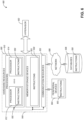
- FIG. 3 illustrates example interfaces of baseband circuitry 204, in accordance with some aspects.
- the baseband circuitry 204 of FIG. 2 may comprise processors 204A-204E and a memory 204G utilized by said processors.
- Each of the processors 204A-204E may include a memory interface, 304A-304E, respectively, to send/receive data to/from the memory 204G.
- the baseband circuitry 204 may further include one or more interfaces to communicatively couple to other circuitries/devices, such as a memory interface 312 (e.g., an interface to send/receive data to/from memory external to the baseband circuitry 204), an application circuitry interface 314 (e.g., an interface to send/receive data to/from the application circuitry 202 of FIG. 2 ), an RF circuitry interface 316 (e.g, an interface to send/receive data to/from RF circuitry 206 of FIG.
- a memory interface 312 e.g., an interface to send/receive data to/from memory external to the baseband circuitry 204
- an application circuitry interface 314 e.g., an interface to send/receive data to/from the application circuitry 202 of FIG. 2
- an RF circuitry interface 316 e.g, an interface to send/receive data to/from RF circuitry 206 of FIG.
- a wireless hardware connectivity interface 318 e.g, an interface to send/receive data to/from Near Field Communication (NFC) components, Bluetooth ® components (e.g, Bluetooth ® Low Energy), Wi-Fi ® components, and other communication components
- a power management interface 320 e.g., an interface to send/receive power or control signals to/from the PMC212.
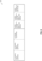
- FIG. 4 is an illustration of a control plane protocol stack in accordance with some aspects.
- a control plane 400 is shown as a communications protocol stack between the UE 102, the RAN node 128 (or alternatively, the RAN node 130), and the AMF 132.
- the PHY layer 401 may in some aspects transmit or receive information used by the MAC layer 402 over one or more air interfaces.
- the PHY layer 401 may further perform link adaptation or adaptive modulation and coding (AMC), power control, cell search (e.g., for initial synchronization and handover purposes), and other measurements used by higher layers, such as the RRC layer 405.
- AMC link adaptation or adaptive modulation and coding
- the PHY layer 401 may in some aspects still further perform error detection on the transport channels, forward error correction (FEC) coding/decoding of the transport channels, modulation/demodulation of physical channels, interleaving rate matching mapping onto physical channels, and Multiple Inp ut Multiple Output (MIMO) antenna processing
- FEC forward error correction
- MIMO Multiple Inp ut Multiple Output
- the MAC layer 402 may in some aspects perform mapping between logical channels and transport channels, multiplexing of MAC service data units (SDUs) from one or more logical channels onto transport blocks (TB) to be delivered to PHY via transport channels, de-multiplexing MAC SDUs to one or more logical channels from transport blocks (TB) delivered from the PHY via transport channels, multiplexing MAC SDUs onto TBs, scheduling information reporting error correction through hybrid automatic repeat request (HARQ), and logical channel prioritization.
- SDUs MAC service data units
- TB transport blocks
- HARQ hybrid automatic repeat request
- the RLC layer 403 may in some aspects operate in a plurality of modes of operation, including Transparent Mode (TM), Unacknowledged Mode (UM), and Acknowledged Mode(AM).
- TheRLC layer 403 may execute transfer of up per lay er protocol data units (PDUs), error correction through automatic repeat request (ARQ) for AM data transfers, and segmentation and reassembly of RLC SDUs for UM and AM data transfers.
- PDUs protocol data units
- ARQ automatic repeat request
- the RLC layer 403 may also maintain sequence numbers independent of the ones in PDCP for UM and AM data transfers.
- the RLC layer 403 may also in some aspects execute re-segmentation of RLC data PDUs for AM data transfers, detect duplicate data for AM data transfers, discard RLC SDUs for UM and AM data transfers, detect protocol errors for AM data transfers, and perform RLC re-establishment.
- the PDCP layer 404 may in some aspects execute header compression and decompression of IP data, maintain PDCP Sequence Numbers (SNs), perform in-sequence delivery of upper layer PDUs at re-establishment of lower layers, perform reordering and eliminate duplicates of lower layer SDUs, execute PDCP PDU routing for the case of split bearers, execute retransmission of lower layer SDUs, cipher and decipher control plane and user plane data, perform integrity protection and integrity verification of control plane and user plane data, control timer-based discard of data, and perform security operations (e.g., ciphering deciphering integrity protection, integrity verification, etc.).
- SNs PDCP Sequence Numbers
- cipher and decipher control plane and user plane data perform integrity protection and integrity verification of control plane and user plane data
- control timer-based discard of data e.g., ciphering deciphering integrity protection, integrity verification, etc.
- primary services and functions of the RRC layer 405 may include broadcast of system information (e.g., included in Master Information Blocks (MIBs) or Sy stem Information Blocks (SIBs) related to the non-access stratum (NAS)); broadcast of system information related to the access stratum (AS); paging initiated by 5GC 120 or NG-RAIV 110, establishment, maintenance, and release of an RRC connection between the UE and NG-RAN (e.g., RRC connection paging, RRC connection establishment, RRC connection addition, RRC connection modification, and RRC connection release, also for carrier aggregation and Dual Connectivity in NR or between E-UTRA and NR); establishment, configuration, maintenance, and release of Signalling Radio Bearers (SRBs) and Data Radio Bearers (DRBs); security functions including key management, mobility functions including handover and context transfer, UE cell selection and reselection and control of cell selection and reselection, and inter-radio access technology (RAT) mobility; and measurement configuration for UE measurement reporting
- Said MIBs and SIBs may comprise one or more information elements (IEs), which may each comprise individual data fields or data structures.
- the RRC layer 405 may also, in some aspects, execute QoS management functions, detection of and recovery from radio link failure, and NAS message transfer between theNAS 406 in the UE and the NAS 406 in the AMF 132.
- the following NAS messages can be communicated during the corresponding NAS procedure, as illustrated in Table 1 below: Table 1 5G NAS Message 5G NAS Procedure 4G NAS Message name 4G NAS Procedure Registration Request Initial registration procedure Attach Request Attach procedure Registration Request Mobility registration up date procedure Tracking Area Update (TAU) Request Tracking area up dating procedure Registration Request Periodic registration update procedure TAU Request Periodic tracking area Deregistration Request Deregistration procedure Detach Request Detach procedure Service Request Service request procedure Service Request or Extended Service Request Service request procedure PDU Session Establishment Request PDU session establishment procedure PDN Connectivity Request PDN connectivity procedure
- the UE 101 and the RAN node 128/130 may utilize an NG radio interface (e.g, an LTE-Uu interface or an NR radio interface) to exchange control plane data via a protocol stack comprising thePHY layer 401, the MAC layer 402, the RLC layer 403, the PDCP layer 404, and the RRC layer 405.
- an NG radio interface e.g, an LTE-Uu interface or an NR radio interface
- the non-access stratum (NAS) protocols 406 form the highest stratum of the control plane between the UE 101 and the AMF 132 as illustrated in FIG. 4 .
- the NAS protocols 406 support the mobility of the UE 101 and the session management procedures to establish and maintain IP connectivity between the UE 101 and the UPF 134.
- the UE protocol stack can include one or more upper layers, above the NAS layer 406.
- the upper layers can include an operating sy stem lay er 424, a connection manager 420, and application layer 422.
- the application layer 422 can include one or more clients which can be used to perform various application functionalities, including providing an interface for and communicating with one or more outside networks.
- the application layer 422 can include an IP multimedia subsystem (IMS) client 426.
- IMS IP multimedia subsystem
- the NG Application Protocol (NG-AP) layer 415 may support the functions of the N2 and N3 interface and comprise Elementary Procedures (EPs).
- An EP is a unit of interaction between the RAN node 128/130 and the 5GC 120.
- the NG-AP layer415 services may comprise two groups: UE-associated services and non UE-associated services. These services perform functions including but not limited to: UE context management, PDU session management and management of corresp ending NG-RAN resources (e.g. Data Radio Bearers [DRBs]), UE capability indication, mobility, NAS signaling transport, and configuration transfer (e.g. for the transfer of SON information).
- DRBs Data Radio Bearers
- the Stream Control Transmission Protocol (SCTP) layer (which may alternatively be referred to as the SCTP/IP layer) 414 may ensure reliable delivery of signaling messages between the RAN node 128/130 and the AMF 132 based, in part, on the IP protocol, supported by the IP layer 413.
- the L2 layer 412 and the L1 layer 411 may refer to communication links (e.g., wired or wireless) used by the RAN node 128/130 and the AMF 132 to exchange information.
- the RAN node 128/130 and the AMF 132 may utilize an N2 interface to exchange control plane data via a protocol stack comprising the L1 layer 411, the L2 layer 412, the IP layer 413, the SCTP layer 414, and the S1-AP layer 415.
- FIG. 5 is an illustration of a user plane protocol stack in accordance with some aspects.
- a user plane 500 is shown as a communications protocol stack between the UE 102, the RAN node 128 (or alternatively, the RAN node 130), and theUPF 134.
- the user plane 500 may utilize at least some of the same protocol layers as the control plane 400.
- the UE 102 and the RAN node 128 may utilize an NR radio interface to exchange user plane data via a protocol stack comprising the PHY layer 401, the MAC layer 402, the RLC layer 403, the PDCP layer 404, and the Service Data Adaptation Protocol (SDAP) layer 416.
- SDAP Service Data Adaptation Protocol
- the SDAP layer 416 may, in some aspects, execute a mapping between a Quality of Service (QoS) flow and a data radio bearer (DRB) and a marking of both DL and UL packets with a QoS flow ID (QFI).
- QoS Quality of Service
- DRB data radio bearer
- QFI QoS flow ID
- an IP protocol stack 513 can be located above the SDAP 416.
- a user datagram protocol (UDP)/ transmission control protocol (TCP) stack 520 can be located above the IP stack 513.
- a session initiation protocol (SIP) stack 522 can be located above the UDP/TCP stack 520, and can be used by the UE 102 and the UPF 134.
- the General Packet Radio Service (GPRS) Tunneling Protocol for the user plane (GTP-U) layer 504 may be used for carrying user data within the 5G core network 120 and between the radio access network 110 and the 5G core network 120.
- the user data transported can be packets in IPv4, IPv6, or PPP formats, for example.
- the UDP and IP security (UDP/IP) layer 503 may provide checksums for data integrity, port numbers for addressing different functions at the source and destination, and encryption and authentication on the selected data flows.
- the RAN node 128/130 and the UPF 134 may utilize an N3 interface to exchange user plane data via a protocol stack comprising the L1 layer 411, the L2 layer 412, the UDP/IP layer 503, and the GTP-U layer 504.
- NAS protocols support the mobility of the UE 101 and the session management procedures to establish and maintain IP connectivity between the UE 101 and the UPF 134.
- FIG. 6 is a block diagram illustrating components, according to some example aspects, able to read instructions from a machine-readable or computer-readable medium (e.g, a non-transitory machine-readable storage medium) and perform any one or more of the methodologies discussed herein.
- FIG. 6 shows a diagrammatic representation of hardware resources 600 including one or more processors (or processor cores) 610, one or more memory/storage devices 620, and one or more communication resources 630, each of which may be communicatively coupled via a bus 640.
- node virtualization e.g., NFV
- a hypervisor 602 may be executed to provide an execution environment for one or more network slices and/or sub-slices to utilize the hardware resources 600
- the processors 610 may include, for example, a processor 612 and a processor 614.
- CPU central processing unit
- RISC reduced instruction set computing
- CISC complex instruction set computing
- GPU graphics processing unit
- DSP digital signal processor
- ASIC application specific integrated circuit
- RFIC radio-frequency integrated circuit
- the memory/storage devices 620 may include main memory, disk storage, or any suitable combination thereof.
- the memory storage devices 620 may include, but are not limited to, any type of volatile or non-volatile memory such as dynamic random access memory (DRAM), static random-access memory (SRAM), erasable programmable read-only memory (EPROM), electrically erasable programmable read-only memory (EEPROM), Flash memory, solid-state storage, etc.
- DRAM dynamic random access memory
- SRAM static random-access memory
- EPROM erasable programmable read-only memory
- EEPROM electrically erasable programmable read-only memory
- Flash memory solid-state storage, etc.
- the communication resources 630 may include interconnection or network interface components or other suitable devices to communicate with one or more peripheral devices 604 or one or more databases 606 via a network 608.
- the communication resources 630 may include wired communication components (e.g., for coupling via a Universal Serial Bus (USB)), cellular communication components, NFC components, Bluetooth ® components (e.g., Bluetooth ® Low Energy), Wi-Fi ® components, and other communication components.
- wired communication components e.g., for coupling via a Universal Serial Bus (USB)
- cellular communication components e.g., for coupling via a Universal Serial Bus (USB)
- NFC components e.g., NFC components
- Bluetooth ® components e.g., Bluetooth ® Low Energy
- Wi-Fi ® components e.g., Wi-Fi ® components
- Instructions 650 may comprise software, a program, an application, an applet, an app, or other executable code for causing at least any of the processors 610 to perform any one or more of the methodologies discussed herein.
- the instructions 650 may reside, completely or partially, within at least one of the processors 610 (e.g., within the processor's cache memory), the memory /storage devices 620, or any suitable combination thereof.
- any portion of the instructions 650 may be transferred to the hardware resources 600 from any combination of the peripheral devices 604 or the databases 606. Accordingly, the memory of processors 610, the memory/storage devices 620, the peripheral devices 604, and the databases 606 are examples of computer-readable and machine-readable media.
- FIG. 7 is an illustration of a default set of access categories in accordance with some aspects.
- 5G access control (AC) mechanisms used within a 5G communication sy stem can take into account at least the following access related information: access class, relationship between the UE and the PLMN the UE is accessing, whether the UE is delay tolerant, and the type of access attempt. Due to the support of different network slices in a 5G communication system, access control can also be based on the network slice that the UE is trying to access.
- 5G AC techniques disclosed herein can be based on the usage of different access categories for purposes of accessing -related information.
- one or more of the following approaches can be used to define the access categories: (a) all access categories are defined in a wireless specification; (b) all access categories are configurable (e.g. via Open Mobile Alliance (OMA) orNAS signaling); and (c) a mixture of approaches (a) and (b).
- OMA Open Mobile Alliance
- NAS signaling e.g. via Open Mobile Alliance (OMA) orNAS signaling
- approach (c) can be used so that some access categories can be predefined and some access categories can be configurable by the mobile operator.
- a 5G wireless architecture could use a standardized (or default) set of access categories, which can be referred to as a "default set of access categories".
- the minimum default set of access categories (and corresponding AC policy rules, describing the mapping of access attempts to these categories), can be common across multiple wireless networks and can be defined within an applicable wireless specification (e.g., one or more 3GPP specifications).
- the default set of access categories can include the following access categories which can be used for prioritizing resources and alleviating congestion in a (V)PLMN: Mobile Originating (MO) signaling (1 category), emergency (1 category), special access classes AC11-15 (5 categories), low priority for machine-typ e communications (MTC) (i.e., Extended Access Barring (EAB) - 3 categories, such as EABa, EABb, and EABc, with each category corresponding to a specific relationship between theUE and the visited PLMN).
- MO Mobile Originating
- EAB Extended Access Barring
- a set of access categories can be provided (e.g., using L3 signalling messages) by the serving PLMN to the UE at initial registration or registration up dates.
- This set of access categories can be used to cover well-known services like IMS voice, IMS video, and SMS.
- This set of access categories can be referred to as the "set of well-known access categories" or the "signaled set" of (well-known) access categories.
- the set of well-known access categories can include MO data (1 category), IM S voice/video (i.e., Service Specific Access Control (SSAC) - 2 categories), and SMS (1 category).
- SSAC Service Specific Access Control
- an additional access category 0 (“null”) can be defined for UE internal processing of paging responses (i.e., this access category can be applicable whenever the UE responds to a paging).
- the network would not broadcast any barring parameters for access category 0, as it is assumed that replying to a paging is always allowed.
- the NAS layer needs to access the network in order to respond to a paging it would indicate access category 0 to the RRC layer, which indicates a request to skip any access barring checks).
- a configurable set of access categories can be provided e.g. through Open Mobile Alliance (OMA) or NAS signaling for use within a PLMN in an op erator-sp ecific way.
- OMA Open Mobile Alliance
- the network operator can define or configure corresponding policy rules associated with the configurable set of access categories.
- the configurable set of access categories can be applied to inbound roamers under the control of a VPLMN (e.g, through peer-to-peer signaling broadcasts or otherwise).
- access categories can be used to enable access control for higher layers that are not part of 3CrPP.
- the Rel-14 LTE functionality of access control for unattended data traffic (UDT), which is controlled at higher layers that are not part of 3GPP, can be implemented to enhance the 5G access control.
- Table 700 illustrating several access categories (e.g, access categories 1 through 8 and A1-A3)that can be used for the default set of access categories.
- Table 700 further includes a UE characteristic or type of access attempt as well as requirements to be met for each of the indicated access categories.
- the default set of access categories can be associated with a UE with access class 11-15 or the following types of access attempt: emergency session, responseto paging, MO signaling MO data, and extended access barring (EAB) for MTC communications.
- EAB extended access barring
- An example communication scenario associated with EAB is as follows.
- UEs registered to that PLMN A can attempt to register to other PLMNs that are available.
- Devices used for MTC are often using a subscription from abroad so that they can register with any PLMN in the visited country.
- the networks can use EAB.
- the UE configured for EAB was registered to PLMN A, so it may have some access control configuration information applicable for PLMN A (received from PLMN A or from its HPLMN), but typically the UE has not been registered to the new selected PLMN B before, and it can only rely on the default set of access categories. If the default set of access categories does not include a category for EAB, then the new inbound roaming UE will use the access category for NIO signalling Thus the UE will get 'better' access conditions than, e.g, a UE configured for EAB which is already registered to PLMN B and has received access control configuration information for PLMN B including the access categories for EAB. Alternatively, if PLMNB activates access control for the access category M O signalling then this will have a negative impact on all UEs in the PLMN.
- UEs configured for EAB communication and the associated access categories can be included in the default set of access categories so that EAB will be considered at initial registration attempts even when the "signaled set” and the "configurable set” of access categories are not available or not y et known by the UE (e.g., at the time the visited network was selected).
- the signaled set of well-known categories can be used by the serving PLMN to better fit access categorization to access attempts. While such functionality can be achieved through the configurable set (i.e., OMAM O), the well-known set allows flexible and efficient way for the serving networkto pick and categorize the access categories to fit certain deployed (basic) services, such as MMTEL video, MMTEL voice, SMS. Using the signaled set of well-known access categories, network operators can also address scenarios where the serving PLMN cannot yet run (or choose not yet to run) OMADM to configure the MO. Moreover, this would lessen the "size" of and the standardization work required for the configurable set of access categories (set 3).
- the signaled information can include the following: (a) what are the well-known services; (b) access categorization of access attempts for the well-known services which are subject to access control; and (c) the respective access categories for the well-known services.
- FIG. 8 is a representation of well-known services that are subject to access control and the access categories associated to such services in accordance with some aspects.
- the well-known services that a network operator wants access control to be applied are MMTEL voice, MMTEL video, and SM S, that serving PLMN can be configured to signal to the UE, some representation of table 800 in FIG. 8 with the above identified information to define the signaled set of well-known access categories.
- the information illustrated in table 800 is exemplary and is a logical representation. Additional configuration information can be signaled by the network operator in a single information element or a series of information elements, or portion of some information can be broadcasted (to multiple UEs) while other portions can be signaled (to one or more specific UEs).
- the UE RRC layer (e.g., 403) can be configured toreceive the following types of information from the UE NAS layer (e.g., 406): the establishment cause, which map s to the information that is shared with the gNB via RRC (for instance msg.3), and other information associated with the access attempt, which could be the access category (instead of the call type).
- the establishment cause which map s to the information that is shared with the gNB via RRC (for instance msg.3)
- other information associated with the access attempt which could be the access category (instead of the call type).
- the establishment cause which map s to the information that is shared with the gNB via RRC (for instance msg.3)
- other information associated with the access attempt which could be the access category (instead of the call type).
- the establishment cause which map s to the information that is shared with the gNB via RRC (for instance msg.3)
- other information associated with the access attempt which could be the access category
- a unified access barring mechanism based on one or more of the techniques described herein can be used in 5G system. More specifically, unified access barring can based on the following techniques described herein: (1) detection of the access category, (2) rules for access categorization, and (3) access barring check for a given access category.
- a new access attempt can be triggered in the following ways:
- a unique (single) layer can be used to handle the mapping to an the access category.
- the unique layer that can handle the mapping can be the NAS layer 406. In this way, the need to define solutions like ACB-skip in LTE can be avoided, which was used due to the independent, duplicate barring being applied by the NAS and the IM Slayer for services like IMS voice.
- the NAS layer can be configured to decide on the associated access category(s) (i.e., theNAS layer would be responsible for performing the mapping between a new access attempt and the access categories, as well as perform all the related interactions with the RRC layer) For IMS voice/video calls, this would be different from LTE, as the IM S client would not be communicating directly with RRC (as with SSAC) but with NAS instead.
- the example communication exchanges illustrated in FIG. 9A and FIG. 9B can be used between the UE NAS layer 406 and the IM S client 426.
- FIG. 9A and FIG. 9B illustrate example communication between a NAS layer 902 and an IMS client 904 for access category detection in accordance with some aspects.
- the NAS layer 902 and the IMS client 904 can be the same as the NAS layer 406 and the IMS client 426, respectively.
- the IM S client 904 indicates to the NAS layer 902 that it wants to send signaling for a new IMS service, e.g. an IM S voice call.
- the NAS layer 902 can notify the IMS client 904 that access is not allowed due to, e.g., congestion, and later, when congestion is alleviated, NAS layer 902 can notify the IMS client 904 again.
- the IMS client 904 may refrain from sending further indications 905 for the same typ e of IM S service, until it receives the notification from theNAS layer that congestion is alleviated.
- the IM S client 904 can be configured to deliver one or more service requests for the IM S service via the user plane when a notification of no congestion is received from the NAS layer 902 at step 906.
- the IMS client 904 can communicate the service requests via session initiation protocol (SIP) signaling via the user plane (e.g., SIP 522).
- SIP session initiation protocol
- the NAS layer 902 can, at 906, explicitly inform the IMS client 904 when barring is alleviated, or, as illustrated in FIG. 9B , the NAS layer 902 can share barring timer (e.g., Tbarring) information with the IMS client 904 at the time that the NAS layer informs the IM S client of the barring condition. In some aspects the IMS client 904 may refrain from sending further indications 905 for the same type of IMS service, until the timer Tbarring expires. At 912, the IMS client 904 can communicate one or more service requests for the IM S service via the user plane when a notification of no congestion is received from the NAS layer 902 at step 910.
- barring timer e.g., Tbarring
- FIG. 10A and FIG. 10B illustrate example communication between a NAS layer 1002 and an RRC layer 1004 for access barring handling in accordance with some aspects.
- the NAS layer 1002 and the RRC layer 1004 can be the same as the NAS layer 406 and the RRC layer 405, respectively.
- FIG. 10A illustrates a NAS layer 1002 configured to map an access attempt into an access category, and an RRC layer 1004, which is configured to handle access barring (including the barring check and barring time) for a given access category.
- the NAS layer 1002 can communicate a request for RRC connection establishment as well as the access category mapped to an access attempt.
- TheRRC layer 1004 can then handle access barring and establishment of the RRC connection.
- FIG. 10B illustrates a communication environment where the NAS layer 1002 is configured to map any access attempts into an access category as well as to handle access barring. More specifically, at 1008, the RRC layer 1004 can send access control information (e.g., as received via a system information block), and can also communicate updates to the NAS layer 1002 at any subsequent time that the access control information changes. The NAS layer 1002 then handles the access attempt mappingto obtain an access category (or categories) as well as it handles access barring associated with the determined access category (or categories).
- access control information e.g., as received via a system information block
- the communication sequence in FIG. 10A can be used.
- the barring timer can be handled by the RRC layer or by theNAS layer.
- the barring time that is triggered by the receipt of an RRC reject message may be handled by RRC (as the NAS layer would not be impacted), unless extended wait time were used similarly to LTE, or it may be handled by the NAS layer.
- the rules defining the mapping of access attempts to access categories can be specified by one or more wireless specifications, where different or same requirements as in LTE can be defined.
- the mapping rules may be defined via a set of rules to be applied in a certain order of precedence or via other the mapping principles (e.g., mapping rules can be specified so that the conditions are disjoint), amongst other options.
- the UE NAS layer can be responsible for checking and applying the policy rules, defining the mapping of access attempts to access categories, and conveying the applicable access category(s) to the access stratum (AS).
- the mapping rules can be formulated in such a way that when applied by theNAS layer, the result is one (or potentially more than one) access category which is indicated to AS for a specific network access attempt.
- the NAS layer would not indicate a new access request for the same access category "x" to the RRC layer, but could indicate to the RRC layer a sub-sequent request for a different access category "y", if the latter is not barred.
- the other category can be of a higher priority - (predefined order of priority or mapped out in the policy rules).
- theNASlayer can be configured to provide only one access category to the RRC layer (and it is up to the NAS layer to determine the access category based on the mapping rules).
- the NAS layer can be configured to indicate to the RRC layer a subsequent request for a different access category, if based on the rules the new access attempt is mapped to this different access category.
- the UE NAS layer may need to take into consideration more than one access category for a given access request:
- mapping rules for access categorization and the procedure howto apply theserules may be configured to support this possible outcome.
- the mapping rules can be checked one-by-one in a certain order of sequence (e.g., defined by a 'precedence level'), until the UE finds the first matching rule, which then defines the (single) applicable access category. This approach, however, maybe insufficient for use cases i) and ii) above.
- a first possible enhancement is to allow that:
- the rules could then be defined in the following way:
- the following additional rule can be inserted at the beginning for paging response:
- the UE can be configured to start with checking rule 1.
- a UE which is not a member of a special access class and initiates an emergency call would detect a match for rule 2.
- the NAS layer would map the access attempt to access category 6 and stop. Therefore, the NAS layer would indicate access category 6 (only) to the RRC layer.
- a UE which is a member of AC 11, 12 and 15 and initiates an emergency call would detect a first match for rule 3.
- the NAS layer would map the access attempt to access category 6 and continue with checking further rules, using the "OR option".
- the UE would then detect that there is a match for rule 4 (as special access class 11 is used), map the access (additionally) to access category 1, and continue with checking further rules.
- the UE would also detect further matches for rules 5 and 8, and map the access (additionally) to access categories 2 and 5, and finally stop after processing rule 9 with a set of access categories including 1, 2, 5 and 6. Therefore, the NAS layer would indicate access categories 1, 2, 5, and 6 to the RRC layer.
- mapping for access for emergency calls and/or with special access classes 11-15 can be configured with a more limited set of eight rules (instead of 63 rules).
- rules for EAB categories a), b), and c) could be specified as follows:
- a UE performing a low priority access with EAB category a) for MO signaling would not detect any match for rules 1 or 9, as it does not initiate an emergency call and does not resp ond to paging. Furthermore, UEs using AC 11-15 do not perform low priority access. The UE would detect a first match for rule 10, so it would map the access attempt to access category A1, and continue with checking further rules, using the "AND option". Next, the UE would detect that there is a match for rule 16, map the access attempt (additionally) to access category 7 and stop. Therefore, the NAS layer can indicate access categories A1 and 7 to the RRC layer. In this regard, a set of 17 (instead of 84) rules would be sufficient to cover the default minimum set of access categories.
- a request for an RRC connection can be mapped to more than one access category.
- a user's access attempt can be barred when it should not (e.g, in the case of a UE that has more than one special AC) or that user's access attempt might be allowed through when more detailed matching of the UE's other characteristics would have result in an access attempt being barred (e.g., when not all of the UE's EAB categories have been checked).
- FIG. 11A , FIG. 11B , and FIG. 11C illustrate table 1100 with example rules and conditions for default and well-known set of access categories in accordance with some aspects.
- table 1100 includes the two proposed sets of access categories illustrated in FIG. 7 and FIG. 8 , together with formulated rules and conditions that need to be applied to derive the access categories to be used for access control when upper layers request access to resources.
- the information of FIG. 7 and FIG. 8 is captured in columns 2, 3 and 4 of table 1100.
- step s can be created to define an order of the processing rules with some precedence in order to perform the checking for these possible multiple access categories. Further explanation is provided in columns 1 and 5 of table 1100.
- the NAS layer can be configured to stop further rule checking to determine other matching access categories. In some aspects, this may be indicated by including a "NOTE 1" or the words “IF MATCHING, STOP " in column 5 of table 1100. With one or more of the "matched" access categories found, the NAS layer can interface with the RRC layer. Access control is passed if it is determined that access is allowed for any of the "matched” access categories. In some aspects, this may be indicated by including a "NOTE 1" in column 5 of table 1100.
- the network will broadcast (e.g., in SIB14) a single bitmap for AC 0 to 9 together with an indication whether this bitmap is applicable for EAB category 'a', 'b' or 'c'.
- TheUE can then determine whether it belongs to the respective category and if yes, whether its own AC is affected by the barring.
- the categories can be defined so that each member of'c' is also a member of 'b', and each member of 'b' is also a member of 'a', i.e., a) ⁇ b) ⁇ c).
- the information to be broadcasted by the network could be defined in different ways.
- the network could broadcast parameters for all 3 categories, and if EAB is applicable only to 'b' and 'c', but not to 'a' (i.e. not to DEs which are in their HPLMN or EHPLMN), then the network could set the barring parameters for 'b' and 'c' to the same values, and the barring parameters for 'a' to values which guarantee a'pass'.
- a UE configured for EAB could be configured to determine the 'highest' category of which it is a member (where 'a' ⁇ 'b' ⁇ 'c'), and map this highest category (e.g.
- the network could broadcast parameters for only one category, e.g. 'b', and it could broadcast additional information, e.g., as for the case in connection with an LTE network above, an indication whether the parameters are applicable for EAB category 'a', 'b' or 'c'.
- the access control check may require the exchange of additional information between the NAS layer and AS.
- the NAS layer can be configured to stop further rule checking to determine other matching access categories. With one or more of the "matched" access categories found, the NAS layer can interface with the RRC layer. Access control can be considered passed if it is determined that access is allowed for all of the "matched" access categories. In some aspects, this may be indicated by including a "NOTE3" in column 5 of table 1100.
- FIG. 12 illustrates generally a flowchart of example functionalities of a method 1200, which can be performed in a 5G wireless architecture (e.g., by a UE) in connection with access control, in accordance with claimed invention.
- sy stem information including access barring parameters for a plurality of access categories for accessing a cell of a next generation Node-B (gNB) can be decoded.
- the plurality of access categories can include a first subset of default access categories and includes a second subset of operator-defined access categories.
- a network access attempt is detected by a control plane layer of the UE that is higher in the protocol stack than a Radio Resource Control (RRC) layer.
- RRC Radio Resource Control
- the network access attempt can be detected by a NAS layer 406.
- the network access attempt is mapped to at least one access category of the plurality of access categories based on a plurality of mapping rules.
- the mapping is e performed by the NAS layer 406 of the control plane.
- an access barring check procedure is performed for the map p ed at least one access category based on the access barring parameters.
- a configuration message is encoded for transmission to a Mobility Management Entity (M ME) associated with the gNB, to perform a network access procedure corresponding to the network access attempt.
- M ME Mobility Management Entity
- FIG. 13 illustrates a block diagram of a communication device such as an evolved Node-B (eNB), a new generation Node-B (gNB), an access point (AP), a wireless station (STA), a mobile station (M S), or a user equipment (UE), in accordance with some aspects.
- the communication device 1300 may operate as a standalone device or may be connected (e.g., networked) to other communication devices.
- Circuitry is a collection of circuits implemented in tangible entities of the device 1300 that include hardware (e.g., simple circuits, gates, logic, etc.). Circuitry membership may be flexible over time. Circuitries include members that may, alone or in combination, perform specified operations when operating. In an example, hardware of the circuitry may be immutably designed to carry out a specific operation (e.g., hardwired). In an example, the hardware of the circuitry may include variably connected physical components (e.g., execution units, transistors, simple circuits, etc.) including a machine-readable medium physically modified (e.g., magnetically, electrically, moveable placement of invariant massed particles, etc.) to encode instructions of the specific operation.
- hardware e.g., processing circuitry
- Circuitry is a collection of circuits implemented in tangible entities of the device 1300 that include hardware (e.g., simple circuits, gates, logic, etc.). Circuitry membership may be flexible over time. Circuitries include members that may, alone or in combination, perform specified operations when
- the underlying electrical properties of a hardware constituent are changed, for example, from an insulator to a conductor or vice versa.
- the instructions enable embedded hardware (e.g., the execution units or a loading mechanism) to create members of the circuitry in hardware via the variable connections to carry out portions of the specific operation when in operation.
- the machine-readable medium elements are part of the circuitry or are communicatively coupled to the other components of the circuitry when the device is operating.
- any of the physical components may be used in more than one member of more than one circuitry.
- execution units may be used in a first circuit of a first circuitry at one point in time and reused by a second circuit in the first circuitry, or by a third circuit in a second circuitry at a different time. Additional examples of these components with respect to the device 1300 follow.
- the device 1300 may operate as a standalone device or may be connected (e.g., networked) to other devices.
- the communication device 1300 may operate in the capacity of a server communication device, a client communication device, or both in server-client network environments.
- the communication device 1300 may act as a peer communication device in peer-to-p eer (P2P) (or other distributed) network environment.
- P2P peer-to-p eer
- the communication device 1300 may be a UE, eNB, PC, a tablet PC, a STB, a PDA, a mobile telephone, a smart phone, a web appliance, a network router, switch or bridge, or any communication device capable of executing instructions (sequential or otherwise) that specify actions to be taken by that communication device.
- the term "communication device” shall also be taken to include any collection of communication devices that individually or jointly execute a set (or multiple sets) of instructions to perform any one or more of the methodologies discussed herein, such as cloud computing software as a service (SaaS), and other computer cluster configurations.
- SaaS cloud computing software as a service
- Examples, as described herein, may include, or may operate on, logic or a number of comp onents, modules, or mechanisms.
- Modules are tangible entities (e.g., hardware) capable of performing specified operations and may be configured or arranged in a certain manner.
- circuits may be arranged (e.g., internally or with respect to external entities such as other circuits) in a specified manner as a module.
- the whole or part of one or more computer systems e.g., a standalone, client or server computer system
- one or more hardware processors may be configured by firmware or software (e.g., instructions, an application portion, or an application) as a module that operates to perform specified operations.
- the software may reside on a communication device-readable medium.
- the software when executed by the underlying hardware of the module, causes the hardware to perform the specified operations.
- module is understood to encompass a tangible entity, be that an entity that is p hy sically constructed, specifically configured (e.g., hardwired), or temporarily (e.g., transitorily) configured (e.g., programmed) to operate in a sp ecified manner or to perform part or all of any operation described herein.
- each of the modules need not be instantiated at any one moment in time.
- the modules comprise a general-purpose hardware processor configured using software
- the general-purpose hardware processor may be configured as respective different modules at different times.
- Software may accordingly configure a hardware processor, for example, to constitute a particular module at one instance of time and to constitute a different module at a different instance of time.
- Communication device e.g., UE 1300 may include a hardware processor 1302 (e.g., a central processing unit (CPU), a graphics processing unit (GPU), a hardware processor core, or any combination thereof), a main memory 1304, a static memory 1306, and mass storage 1307 (e.g., hard drive, tape drive, flash storage, or other block or storage devices), some or all of which may communicate with each other via an interlink (e.g., bus) 1308.
- a hardware processor 1302 e.g., a central processing unit (CPU), a graphics processing unit (GPU), a hardware processor core, or any combination thereof
- main memory 1304 e.g., main memory 1304, a static memory 1306, and mass storage 1307 (e.g., hard drive, tape drive, flash storage, or other block or storage devices), some or all of which may communicate with each other via an interlink (e.g., bus) 1308.
- mass storage 1307 e.g., hard drive, tape drive, flash storage,
- the communication device 1300 may further include a display device 1310, an alphanumeric input device 1312 (e.g., a keyboard), and a user interface (UI) navigation device 1314 (e.g., a mouse).
- UI user interface
- the display device 1310, input device 1312 and UI navigation device 1314 may be a touch screen display.
- the communication device 1300 may additionally include a signal generation device 1318 (e.g., a speaker), a network interface device 1320, and one or more sensors 1321, such as a global positioning system (GPS) sensor, compass, accelerometer, or other sensor.
- GPS global positioning system
- the communication device 1300 may include an output controller 1328, such as a serial (e.g., universal serial bus (USB), parallel, or other wired or wireless (e.g., infrared (IR), near field communication (NFC), etc.) connection to communicate or control one or more peripheral devices (e.g., a printer, card reader, etc.).
- a serial e.g., universal serial bus (USB), parallel, or other wired or wireless (e.g., infrared (IR), near field communication (NFC), etc.) connection to communicate or control one or more peripheral devices (e.g., a printer, card reader, etc.).
- USB universal serial bus
- IR infrared
- NFC near field communication
- the storage device 1307 may include a communication device-readable medium 1322, on which is stored one or more sets of data structures or instructions 1324 (e.g., software) embodying or utilized by any one or more of the techniques or functions described herein.
- registers of the processor 1302, the main memory 1304, the static memory 1306, and/or the mass storage 1307 may be, or include (completely or at least partially), the device-readable medium 1322, on which is stored the one or more sets of data structures or instructions 1324, embodying or utilized by any one or more of the techniques or functions described herein.
- one or any combination of the hardware processor 1302, the main memory 1304, the static memory 1306, or the mass storage 1316 may constitute the device-readable medium 1322.
- the term “device-readable medium” is interchangeable with “computer-readable medium” or “machine-readable medium”. While the communication device-readable medium 1322 is illustrated as a single medium, the term “communication device-readable medium” may include a single medium or multiple media (e.g., a centralized or distributed database, and/or associated caches and servers) configured to store the one or more instructions 1324.
- the term "communication device-readable medium” may include any medium that is capable of storing, encoding or carrying instructions (e.g., instructions 1324) for execution by the communication device 1300 and that cause the communication device 1300 to perform any one or more of the techniques of the present disclosure, or that is capable of storing encoding or carrying data structures used by or associated with such instructions.
- Nonlimiting communication device-readable medium examples may include solid-state memories, and optical and magnetic media.
- communication device-readable media may include: non-volatile memory, such as semiconductor memory devices (e.g., Electrically Programmable Read-Only Memory (EPROM), Electrically Erasable Programmable Read-Only Memory (EEPROM)) and flash memory devices; magnetic disks, such as internal hard disks and removable disks; magneto-optical disks; Random Access Memory (RAM); and CD-ROM and DVD-ROM disks.
- non-volatile memory such as semiconductor memory devices (e.g., Electrically Programmable Read-Only Memory (EPROM), Electrically Erasable Programmable Read-Only Memory (EEPROM)) and flash memory devices
- magnetic disks such as internal hard disks and removable disks
- magneto-optical disks Random Access Memory (RAM); and CD-ROM and DVD-ROM disks.
- communication device-readable media may include non-transitory communication device-readable media.
- communication device-readable media may include communication device-readable media that is not a transitory prop acting signal.
- the instructions 1324 may further be transmitted or received over a communications network 1326 using a transmission medium via the network interface device 1320 utilizing any one of a number of transfer protocols (e.g., frame relay, internet protocol (IP), transmission control protocol (TCP), user datagram protocol (UDP), hypertext transfer protocol (HTTP), etc.).
- transfer protocols e.g., frame relay, internet protocol (IP), transmission control protocol (TCP), user datagram protocol (UDP), hypertext transfer protocol (HTTP), etc.
- Example communication networks may include a local area network (LAN), a wide area network(WAN), a packet data network (e.g., the Internet), mobile telephone networks (e.g., cellular networks), Plain Old Telephone (POTS) networks, and wireless data networks (e.g., Institute of Electrical and Electronics Engineers (IEEE) 802.11 family of standards known as Wi-Fi ® , IEEE 802.16 family of standards known as WiMax ® ), IEEE 802.15.4 family of standards, a Long Term Evolution(LTE) family of standards, a Universal Mobile Telecommunications Sy stem (UM T S) family of standards, p eer-to-p eer (P2P) networks, among others.
- LAN local area network
- WAN wide area network
- packet data network e.g., the Internet
- mobile telephone networks e.g., cellular networks
- wireless data networks e.g., Institute of Electrical and Electronics Engineers (IEEE) 802.11 family of standards known as Wi-
- the network interface device 1320 may include one or more physical jacks (e.g., Ethernet, coaxial, or phonejacks) or one or more antennas to connect to the communications network 1326.
- the network interface device 1320 may include a plurality of antennas to wirelessly communicate using at least one of single-input multiple-output (SIMO), MIMO, or multiple-input single-output (MISO) techniques.
- SIMO single-input multiple-output
- MIMO multiple-input single-output
- MISO multiple-input single-output
- the network interface device 1320 may wirelessly communicate using Multiple User M IM O techniques.
- transmission medium shall be taken to include any intangible medium that is capable of storing encoding or carrying instructions for execution by the communication device 1300, and includes digital or analog communications signals or other intangible medium to facilitate communication of such software.
- a transmission medium in the context of this disclosure is a device-readable medium.
Landscapes
- Engineering & Computer Science (AREA)
- Computer Networks & Wireless Communication (AREA)
- Signal Processing (AREA)
- Computer Security & Cryptography (AREA)
- Databases & Information Systems (AREA)
- Mobile Radio Communication Systems (AREA)
Priority Applications (1)
| Application Number | Priority Date | Filing Date | Title |
|---|---|---|---|
| EP22199855.2A EP4138461A1 (en) | 2017-05-05 | 2018-05-03 | Access control mechanism |
Applications Claiming Priority (3)
| Application Number | Priority Date | Filing Date | Title |
|---|---|---|---|
| US201762502393P | 2017-05-05 | 2017-05-05 | |
| US201762542701P | 2017-08-08 | 2017-08-08 | |
| PCT/US2018/030840 WO2018204609A1 (en) | 2017-05-05 | 2018-05-03 | Access control mechanism |
Related Child Applications (2)
| Application Number | Title | Priority Date | Filing Date |
|---|---|---|---|
| EP22199855.2A Division EP4138461A1 (en) | 2017-05-05 | 2018-05-03 | Access control mechanism |
| EP22199855.2A Division-Into EP4138461A1 (en) | 2017-05-05 | 2018-05-03 | Access control mechanism |
Publications (4)
| Publication Number | Publication Date |
|---|---|
| EP3619955A1 EP3619955A1 (en) | 2020-03-11 |
| EP3619955A4 EP3619955A4 (en) | 2020-12-02 |
| EP3619955C0 EP3619955C0 (en) | 2024-01-24 |
| EP3619955B1 true EP3619955B1 (en) | 2024-01-24 |
Family
ID=64016685
Family Applications (2)
| Application Number | Title | Priority Date | Filing Date |
|---|---|---|---|
| EP18794459.0A Active EP3619955B1 (en) | 2017-05-05 | 2018-05-03 | Access control mechanism |
| EP22199855.2A Pending EP4138461A1 (en) | 2017-05-05 | 2018-05-03 | Access control mechanism |
Family Applications After (1)
| Application Number | Title | Priority Date | Filing Date |
|---|---|---|---|
| EP22199855.2A Pending EP4138461A1 (en) | 2017-05-05 | 2018-05-03 | Access control mechanism |
Country Status (4)
| Country | Link |
|---|---|
| US (1) | US11160006B2 (zh) |
| EP (2) | EP3619955B1 (zh) |
| CN (2) | CN115720358A (zh) |
| WO (1) | WO2018204609A1 (zh) |
Families Citing this family (25)
| Publication number | Priority date | Publication date | Assignee | Title |
|---|---|---|---|---|
| CN108377527B (zh) * | 2016-11-02 | 2021-02-26 | 华为技术有限公司 | 一种适应灵活部署场景的网络架构 |
| CN114125964B (zh) * | 2017-01-06 | 2024-04-05 | 北京三星通信技术研究有限公司 | 用于无线网络系统之间的数据传送控制的方法及设备 |
| JP6381058B1 (ja) * | 2017-06-09 | 2018-08-29 | Necプラットフォームズ株式会社 | Ponシステム及び通信制御方法 |
| EP4075871A1 (en) * | 2017-06-19 | 2022-10-19 | IDAC Holdings, Inc. | User plane relocation |
| KR102327904B1 (ko) | 2017-08-09 | 2021-11-19 | 지티이 코포레이션 | 사용자 평면을 분리하기 위한 서비스 품질 구현들 |
| CN109413639A (zh) * | 2017-08-15 | 2019-03-01 | 维沃移动通信有限公司 | 一种终端可达性管理方法、核心网及接入网 |
| CN111052818B (zh) * | 2017-09-05 | 2021-10-22 | 华为技术有限公司 | 网络实体、用户设备和网络切片的控制和使用方法 |
| WO2019149185A1 (en) * | 2018-01-31 | 2019-08-08 | Telefonaktiebolaget Lm Ericsson (Publ) | Methods and devices for status exposure in wireless communication networks |
| US11382012B2 (en) * | 2018-05-10 | 2022-07-05 | Lg Electronics Inc. | Method and apparatus for deprioritizing access on unlicensed band based on UE preference in wireless communication system |
| CN110621080A (zh) * | 2018-06-19 | 2019-12-27 | 夏普株式会社 | 接入控制方法及用户设备 |
| WO2020036882A1 (en) * | 2018-08-13 | 2020-02-20 | Intel Corporation | Local area network (lan) service in fifth generation (5g) systems |
| WO2020106204A1 (en) * | 2018-11-19 | 2020-05-28 | Telefonaktiebolaget Lm Ericsson (Publ) | Radio network node, network node and methods for setting up a secure connection to the user equipment (ue) |
| CN114557044B (zh) * | 2019-08-07 | 2023-11-17 | Lg电子株式会社 | Ims信令 |
| US11140117B1 (en) * | 2020-03-20 | 2021-10-05 | Sprint Communication Company L.P. | Wireless messaging with high-priority quality-of-service |
| US20230199618A1 (en) * | 2020-04-14 | 2023-06-22 | Telefonaktiebolaget Lm Ericsson (Publ) | Network Node, User Equipment and Methods in a Radio Communications Network |
| US20210392653A1 (en) * | 2020-04-30 | 2021-12-16 | Qualcomm Incorporated | Unmanned aerial vehicle category reporting |
| CN111970703A (zh) * | 2020-06-24 | 2020-11-20 | 重庆邮电大学 | NB-IoT中的一种上行通信资源优化的方法 |
| WO2022021155A1 (en) * | 2020-07-29 | 2022-02-03 | Lenovo (Beijing) Limited | Method and apparatus for managing access control information |
| US20220141754A1 (en) * | 2020-11-05 | 2022-05-05 | Apple Inc. | Unified access control improvements |
| US11874817B2 (en) | 2021-03-31 | 2024-01-16 | Bank Of America Corporation | Optimizing distributed and parallelized batch data processing |
| US11474881B1 (en) | 2021-03-31 | 2022-10-18 | Bank Of America Corporation | Optimizing distributed and parallelized batch data processing |
| US11792690B2 (en) * | 2021-08-26 | 2023-10-17 | Apple Inc. | Enhanced packet filtering |
| US20230102956A1 (en) * | 2021-09-24 | 2023-03-30 | Apple Inc. | Unified Access Control for a Cellular Network |
| WO2023085519A1 (ko) * | 2021-11-11 | 2023-05-19 | 엘지전자 주식회사 | 무선 통신 시스템에서 단말 동작 방법 및 장치 |
| WO2024003830A1 (en) * | 2022-06-29 | 2024-01-04 | Jio Platforms Limited | System and method for enhanced change handling of a public land mobile network |
Family Cites Families (19)
| Publication number | Priority date | Publication date | Assignee | Title |
|---|---|---|---|---|
| CN106055930A (zh) * | 2010-11-05 | 2016-10-26 | 交互数字专利控股公司 | 设备检验和遇险指示 |
| CN102612112B (zh) * | 2011-01-21 | 2018-01-30 | 中兴通讯股份有限公司 | 一种终端接入方法及装置 |
| JP4965718B1 (ja) * | 2011-02-21 | 2012-07-04 | 株式会社エヌ・ティ・ティ・ドコモ | 移動機におけるネットワークアクセス規制方法及び移動機並びに移動機に用いられるプロセッサ |
| CN102892177B (zh) * | 2011-07-20 | 2018-01-02 | 中兴通讯股份有限公司 | 一种终端接入控制处理方法及装置 |
| CN102300285B (zh) * | 2011-09-29 | 2014-02-12 | 电信科学技术研究院 | 接入控制方法和设备 |
| KR102096258B1 (ko) * | 2012-03-21 | 2020-05-27 | 삼성전자 주식회사 | 그래뉼러 네트워크 액세스 제어 및 그 방법 |
| KR20150020284A (ko) * | 2012-06-18 | 2015-02-25 | 엘지전자 주식회사 | 무선랜에서 초기 액세스 방법 및 장치 |
| US9392531B2 (en) * | 2014-01-30 | 2016-07-12 | Intel IP Corporation | Application specific congestion control in a wireless network |
| US9775011B2 (en) * | 2014-01-31 | 2017-09-26 | Intel Corporation | Implementations of application specific access class barring skip functionality in a wireless network |
| CN105659691A (zh) * | 2014-03-19 | 2016-06-08 | Lg电子株式会社 | 用于服务请求过程的执行方法和用户设备 |
| WO2016006948A1 (en) * | 2014-07-09 | 2016-01-14 | Lg Electronics Inc. | Method and apparatus for performing application specific access control in wireless communication system |
| MX369907B (es) | 2014-07-11 | 2019-11-26 | Lg Electronics Inc | Metodo y aparato para realizar control de acceso para comparticion de red en sistema de comunicacion inalambrica. |
| WO2016076606A1 (ko) * | 2014-11-10 | 2016-05-19 | 엘지전자 주식회사 | Acdc에 의한 네트워크 액세스 차단 방법 및 사용자 장치 |
| US9641993B2 (en) * | 2015-06-30 | 2017-05-02 | Verizon Patent And Licensing Inc. | Access class barring and redirecting of emergency calls |
| JP6822402B2 (ja) * | 2015-07-28 | 2021-01-27 | 日本電気株式会社 | 無線端末及びその方法 |
| US20180199261A1 (en) * | 2015-09-10 | 2018-07-12 | Lg Electronics Inc. | Method and apparatus for performing access barring check for high priority access in wireless communication system |
| US11044776B2 (en) * | 2016-03-27 | 2021-06-22 | Lg Electronics Inc. | Method for attempting network access from NB-IoT RAT |
| WO2018194270A1 (ko) * | 2017-04-18 | 2018-10-25 | 엘지전자 주식회사 | 액세스 금지 체크를 수행하는 방법 및 장치 |
| MX2019012560A (es) * | 2017-05-05 | 2020-01-20 | Ericsson Telefon Ab L M | Categoria de acceso y causa de establecimiento. |
-
2018
- 2018-05-03 WO PCT/US2018/030840 patent/WO2018204609A1/en active Application Filing
- 2018-05-03 CN CN202211528113.XA patent/CN115720358A/zh active Pending
- 2018-05-03 US US16/499,067 patent/US11160006B2/en active Active
- 2018-05-03 EP EP18794459.0A patent/EP3619955B1/en active Active
- 2018-05-03 CN CN201880027853.0A patent/CN110574431B/zh active Active
- 2018-05-03 EP EP22199855.2A patent/EP4138461A1/en active Pending
Also Published As
| Publication number | Publication date |
|---|---|
| EP3619955C0 (en) | 2024-01-24 |
| WO2018204609A1 (en) | 2018-11-08 |
| CN110574431A (zh) | 2019-12-13 |
| CN110574431B (zh) | 2022-11-25 |
| US11160006B2 (en) | 2021-10-26 |
| EP4138461A1 (en) | 2023-02-22 |
| US20210092668A1 (en) | 2021-03-25 |
| EP3619955A1 (en) | 2020-03-11 |
| CN115720358A (zh) | 2023-02-28 |
| EP3619955A4 (en) | 2020-12-02 |
Similar Documents
| Publication | Publication Date | Title |
|---|---|---|
| EP3619955B1 (en) | Access control mechanism | |
| EP3462804B1 (en) | Signaling radio bearer type 3 (srb3) and secondary cell group (scg) failure handling | |
| EP3625984B1 (en) | Per ue network controlled small gap (ncsg) signalling | |
| US10925116B2 (en) | Beam indication for semi-persistent and grant-free transmissions | |
| US11026233B2 (en) | Emission and panel aware beam selection | |
| US10986539B2 (en) | Solution for vehicle-to-everything (V2X) communication authorization in 5G system | |
| EP3679681B1 (en) | Phase tracking reference signal (pt-rs) configuration | |
| US10716096B2 (en) | Enabling network slicing in a 5G network with CP/UP separation | |
| US11399413B2 (en) | Physical random access channel (PRACH) format configuration | |
| US11304157B2 (en) | Collision handling of synchronization signal (SS) blocks | |
| EP3616448B1 (en) | Multefire architecture for cellular internet-of-things (ciot) | |
| US20210153027A1 (en) | Multefire Architecture Supporting Access Classes and Barring |
Legal Events
| Date | Code | Title | Description |
|---|---|---|---|
| STAA | Information on the status of an ep patent application or granted ep patent |
Free format text: STATUS: THE INTERNATIONAL PUBLICATION HAS BEEN MADE |
|
| PUAI | Public reference made under article 153(3) epc to a published international application that has entered the european phase |
Free format text: ORIGINAL CODE: 0009012 |
|
| STAA | Information on the status of an ep patent application or granted ep patent |
Free format text: STATUS: REQUEST FOR EXAMINATION WAS MADE |
|
| 17P | Request for examination filed |
Effective date: 20191105 |
|
| AK | Designated contracting states |
Kind code of ref document: A1 Designated state(s): AL AT BE BG CH CY CZ DE DK EE ES FI FR GB GR HR HU IE IS IT LI LT LU LV MC MK MT NL NO PL PT RO RS SE SI SK SM TR |
|
| AX | Request for extension of the european patent |
Extension state: BA ME |
|
| DAV | Request for validation of the european patent (deleted) | ||
| DAX | Request for extension of the european patent (deleted) | ||
| RIN1 | Information on inventor provided before grant (corrected) |
Inventor name: BURBIDGE, RICHARD, C. Inventor name: PINHEIRO, ANA, LUCIA Inventor name: STOJANOVSKI, ALEXANDRE, SASO Inventor name: ZAUS, ROBERT Inventor name: PALAT, SUDEEP, K. Inventor name: MARTINEZ TARRADELL, MARTA Inventor name: CHIN, CHEN-HO |
|
| A4 | Supplementary search report drawn up and despatched |
Effective date: 20201030 |
|
| RIC1 | Information provided on ipc code assigned before grant |
Ipc: H04W 48/02 20090101AFI20201026BHEP Ipc: H04W 48/14 20090101ALN20201026BHEP |
|
| RAP1 | Party data changed (applicant data changed or rights of an application transferred) |
Owner name: APPLE INC. |
|
| STAA | Information on the status of an ep patent application or granted ep patent |
Free format text: STATUS: EXAMINATION IS IN PROGRESS |
|
| 17Q | First examination report despatched |
Effective date: 20220513 |
|
| RIC1 | Information provided on ipc code assigned before grant |
Ipc: H04W 48/14 20090101ALN20230116BHEP Ipc: H04W 48/02 20090101AFI20230116BHEP |
|
| RIC1 | Information provided on ipc code assigned before grant |
Ipc: H04W 48/14 20090101ALN20230125BHEP Ipc: H04W 48/02 20090101AFI20230125BHEP |
|
| GRAP | Despatch of communication of intention to grant a patent |
Free format text: ORIGINAL CODE: EPIDOSNIGR1 |
|
| STAA | Information on the status of an ep patent application or granted ep patent |
Free format text: STATUS: GRANT OF PATENT IS INTENDED |
|
| RIC1 | Information provided on ipc code assigned before grant |
Ipc: H04W 48/14 20090101ALN20230220BHEP Ipc: H04W 48/02 20090101AFI20230220BHEP |
|
| INTG | Intention to grant announced |
Effective date: 20230316 |
|
| GRAJ | Information related to disapproval of communication of intention to grant by the applicant or resumption of examination proceedings by the epo deleted |
Free format text: ORIGINAL CODE: EPIDOSDIGR1 |
|
| STAA | Information on the status of an ep patent application or granted ep patent |
Free format text: STATUS: EXAMINATION IS IN PROGRESS |
|
| INTC | Intention to grant announced (deleted) | ||
| GRAP | Despatch of communication of intention to grant a patent |
Free format text: ORIGINAL CODE: EPIDOSNIGR1 |
|
| STAA | Information on the status of an ep patent application or granted ep patent |
Free format text: STATUS: GRANT OF PATENT IS INTENDED |
|
| RIC1 | Information provided on ipc code assigned before grant |
Ipc: H04W 48/14 20090101ALN20230731BHEP Ipc: H04W 48/02 20090101AFI20230731BHEP |
|
| RIC1 | Information provided on ipc code assigned before grant |
Ipc: H04W 48/14 20090101ALN20230811BHEP Ipc: H04W 48/02 20090101AFI20230811BHEP |
|
| INTG | Intention to grant announced |
Effective date: 20230905 |
|
| GRAS | Grant fee paid |
Free format text: ORIGINAL CODE: EPIDOSNIGR3 |
|
| GRAA | (expected) grant |
Free format text: ORIGINAL CODE: 0009210 |
|
| STAA | Information on the status of an ep patent application or granted ep patent |
Free format text: STATUS: THE PATENT HAS BEEN GRANTED |
|
| AK | Designated contracting states |
Kind code of ref document: B1 Designated state(s): AL AT BE BG CH CY CZ DE DK EE ES FI FR GB GR HR HU IE IS IT LI LT LU LV MC MK MT NL NO PL PT RO RS SE SI SK SM TR |
|
| REG | Reference to a national code |
Ref country code: GB Ref legal event code: FG4D |
|
| REG | Reference to a national code |
Ref country code: CH Ref legal event code: EP |
|
| REG | Reference to a national code |
Ref country code: DE Ref legal event code: R096 Ref document number: 602018064533 Country of ref document: DE |
|
| REG | Reference to a national code |
Ref country code: IE Ref legal event code: FG4D |
|
| U01 | Request for unitary effect filed |
Effective date: 20240206 |
|
| U07 | Unitary effect registered |
Designated state(s): AT BE BG DE DK EE FI FR IT LT LU LV MT NL PT SE SI Effective date: 20240214 |