EP3618939B1 - An oil housing, filter element, and valving assembly for providing pre-charged oil volume changes - Google Patents
An oil housing, filter element, and valving assembly for providing pre-charged oil volume changes Download PDFInfo
- Publication number
- EP3618939B1 EP3618939B1 EP18723442.2A EP18723442A EP3618939B1 EP 3618939 B1 EP3618939 B1 EP 3618939B1 EP 18723442 A EP18723442 A EP 18723442A EP 3618939 B1 EP3618939 B1 EP 3618939B1
- Authority
- EP
- European Patent Office
- Prior art keywords
- housing
- valve
- seal member
- contaminated
- clean
- Prior art date
- Legal status (The legal status is an assumption and is not a legal conclusion. Google has not performed a legal analysis and makes no representation as to the accuracy of the status listed.)
- Active
Links
Images




Classifications
-
- F—MECHANICAL ENGINEERING; LIGHTING; HEATING; WEAPONS; BLASTING
- F01—MACHINES OR ENGINES IN GENERAL; ENGINE PLANTS IN GENERAL; STEAM ENGINES
- F01M—LUBRICATING OF MACHINES OR ENGINES IN GENERAL; LUBRICATING INTERNAL COMBUSTION ENGINES; CRANKCASE VENTILATING
- F01M1/00—Pressure lubrication
- F01M1/10—Lubricating systems characterised by the provision therein of lubricant venting or purifying means, e.g. of filters
-
- F—MECHANICAL ENGINEERING; LIGHTING; HEATING; WEAPONS; BLASTING
- F01—MACHINES OR ENGINES IN GENERAL; ENGINE PLANTS IN GENERAL; STEAM ENGINES
- F01M—LUBRICATING OF MACHINES OR ENGINES IN GENERAL; LUBRICATING INTERNAL COMBUSTION ENGINES; CRANKCASE VENTILATING
- F01M11/00—Component parts, details or accessories, not provided for in, or of interest apart from, groups F01M1/00 - F01M9/00
- F01M11/03—Mounting or connecting of lubricant purifying means relative to the machine or engine; Details of lubricant purifying means
-
- B—PERFORMING OPERATIONS; TRANSPORTING
- B01—PHYSICAL OR CHEMICAL PROCESSES OR APPARATUS IN GENERAL
- B01D—SEPARATION
- B01D27/00—Cartridge filters of the throw-away type
- B01D27/08—Construction of the casing
-
- B—PERFORMING OPERATIONS; TRANSPORTING
- B01—PHYSICAL OR CHEMICAL PROCESSES OR APPARATUS IN GENERAL
- B01D—SEPARATION
- B01D29/00—Filters with filtering elements stationary during filtration, e.g. pressure or suction filters, not covered by groups B01D24/00 - B01D27/00; Filtering elements therefor
- B01D29/11—Filters with filtering elements stationary during filtration, e.g. pressure or suction filters, not covered by groups B01D24/00 - B01D27/00; Filtering elements therefor with bag, cage, hose, tube, sleeve or like filtering elements
- B01D29/13—Supported filter elements
- B01D29/15—Supported filter elements arranged for inward flow filtration
-
- B—PERFORMING OPERATIONS; TRANSPORTING
- B01—PHYSICAL OR CHEMICAL PROCESSES OR APPARATUS IN GENERAL
- B01D—SEPARATION
- B01D35/00—Filtering devices having features not specifically covered by groups B01D24/00 - B01D33/00, or for applications not specifically covered by groups B01D24/00 - B01D33/00; Auxiliary devices for filtration; Filter housing constructions
- B01D35/14—Safety devices specially adapted for filtration; Devices for indicating clogging
- B01D35/147—Bypass or safety valves
-
- B—PERFORMING OPERATIONS; TRANSPORTING
- B01—PHYSICAL OR CHEMICAL PROCESSES OR APPARATUS IN GENERAL
- B01D—SEPARATION
- B01D35/00—Filtering devices having features not specifically covered by groups B01D24/00 - B01D33/00, or for applications not specifically covered by groups B01D24/00 - B01D33/00; Auxiliary devices for filtration; Filter housing constructions
- B01D35/14—Safety devices specially adapted for filtration; Devices for indicating clogging
- B01D35/153—Anti-leakage or anti-return valves
-
- B—PERFORMING OPERATIONS; TRANSPORTING
- B01—PHYSICAL OR CHEMICAL PROCESSES OR APPARATUS IN GENERAL
- B01D—SEPARATION
- B01D35/00—Filtering devices having features not specifically covered by groups B01D24/00 - B01D33/00, or for applications not specifically covered by groups B01D24/00 - B01D33/00; Auxiliary devices for filtration; Filter housing constructions
- B01D35/30—Filter housing constructions
-
- B—PERFORMING OPERATIONS; TRANSPORTING
- B01—PHYSICAL OR CHEMICAL PROCESSES OR APPARATUS IN GENERAL
- B01D—SEPARATION
- B01D35/00—Filtering devices having features not specifically covered by groups B01D24/00 - B01D33/00, or for applications not specifically covered by groups B01D24/00 - B01D33/00; Auxiliary devices for filtration; Filter housing constructions
- B01D35/30—Filter housing constructions
- B01D35/306—Filter mounting adapter
-
- F—MECHANICAL ENGINEERING; LIGHTING; HEATING; WEAPONS; BLASTING
- F16—ENGINEERING ELEMENTS AND UNITS; GENERAL MEASURES FOR PRODUCING AND MAINTAINING EFFECTIVE FUNCTIONING OF MACHINES OR INSTALLATIONS; THERMAL INSULATION IN GENERAL
- F16N—LUBRICATING
- F16N39/00—Arrangements for conditioning of lubricants in the lubricating system
- F16N39/06—Arrangements for conditioning of lubricants in the lubricating system by filtration
-
- B—PERFORMING OPERATIONS; TRANSPORTING
- B01—PHYSICAL OR CHEMICAL PROCESSES OR APPARATUS IN GENERAL
- B01D—SEPARATION
- B01D2201/00—Details relating to filtering apparatus
- B01D2201/16—Valves
- B01D2201/167—Single-way valves
-
- B—PERFORMING OPERATIONS; TRANSPORTING
- B01—PHYSICAL OR CHEMICAL PROCESSES OR APPARATUS IN GENERAL
- B01D—SEPARATION
- B01D2201/00—Details relating to filtering apparatus
- B01D2201/29—Filter cartridge constructions
-
- B—PERFORMING OPERATIONS; TRANSPORTING
- B01—PHYSICAL OR CHEMICAL PROCESSES OR APPARATUS IN GENERAL
- B01D—SEPARATION
- B01D2201/00—Details relating to filtering apparatus
- B01D2201/40—Special measures for connecting different parts of the filter
- B01D2201/4023—Means for connecting filter housings to supports
-
- F—MECHANICAL ENGINEERING; LIGHTING; HEATING; WEAPONS; BLASTING
- F01—MACHINES OR ENGINES IN GENERAL; ENGINE PLANTS IN GENERAL; STEAM ENGINES
- F01M—LUBRICATING OF MACHINES OR ENGINES IN GENERAL; LUBRICATING INTERNAL COMBUSTION ENGINES; CRANKCASE VENTILATING
- F01M1/00—Pressure lubrication
- F01M1/10—Lubricating systems characterised by the provision therein of lubricant venting or purifying means, e.g. of filters
- F01M2001/1007—Lubricating systems characterised by the provision therein of lubricant venting or purifying means, e.g. of filters characterised by the purification means combined with other functions
-
- F—MECHANICAL ENGINEERING; LIGHTING; HEATING; WEAPONS; BLASTING
- F01—MACHINES OR ENGINES IN GENERAL; ENGINE PLANTS IN GENERAL; STEAM ENGINES
- F01M—LUBRICATING OF MACHINES OR ENGINES IN GENERAL; LUBRICATING INTERNAL COMBUSTION ENGINES; CRANKCASE VENTILATING
- F01M1/00—Pressure lubrication
- F01M1/10—Lubricating systems characterised by the provision therein of lubricant venting or purifying means, e.g. of filters
- F01M2001/105—Lubricating systems characterised by the provision therein of lubricant venting or purifying means, e.g. of filters characterised by the layout of the purification arrangements
- F01M2001/1085—Lubricating systems characterised by the provision therein of lubricant venting or purifying means, e.g. of filters characterised by the layout of the purification arrangements comprising non-return valves
-
- F—MECHANICAL ENGINEERING; LIGHTING; HEATING; WEAPONS; BLASTING
- F01—MACHINES OR ENGINES IN GENERAL; ENGINE PLANTS IN GENERAL; STEAM ENGINES
- F01M—LUBRICATING OF MACHINES OR ENGINES IN GENERAL; LUBRICATING INTERNAL COMBUSTION ENGINES; CRANKCASE VENTILATING
- F01M11/00—Component parts, details or accessories, not provided for in, or of interest apart from, groups F01M1/00 - F01M9/00
- F01M11/03—Mounting or connecting of lubricant purifying means relative to the machine or engine; Details of lubricant purifying means
- F01M2011/031—Mounting or connecting of lubricant purifying means relative to the machine or engine; Details of lubricant purifying means characterised by mounting means
-
- F—MECHANICAL ENGINEERING; LIGHTING; HEATING; WEAPONS; BLASTING
- F16—ENGINEERING ELEMENTS AND UNITS; GENERAL MEASURES FOR PRODUCING AND MAINTAINING EFFECTIVE FUNCTIONING OF MACHINES OR INSTALLATIONS; THERMAL INSULATION IN GENERAL
- F16N—LUBRICATING
- F16N39/00—Arrangements for conditioning of lubricants in the lubricating system
- F16N39/06—Arrangements for conditioning of lubricants in the lubricating system by filtration
- F16N2039/065—Arrangements for conditioning of lubricants in the lubricating system by filtration inlet foot filter
Definitions
- the present disclosure generally relates to the field of oil filtration and methods of changing oil and replacing filter elements thereof.
- the detachment of a used filter element can contain used oil which can then drip, drain, or otherwise spill out of the filter element upon separation from the mount or housing and thus result in further required cleaning of the equipment itself or the floor or ground underneath the equipment.
- the drain and refill process of the used oil can also be messy and time consuming, as well as difficult to dispose of when finished.
- an element assembly having a filter element for filtering oil for lubricating an internal combustion engine is known;
- the oil inlet side of the filter housing can be made to flow from an oil inlet side of the filter housing to the element assembly side in accordance with an increase in the pressure of the sewage oil delivered from the internal combustion engine side.
- An inlet side anti-drain valve is moved in conjunction with a loosening operation of the cap coupled with the filter housing, and is capable of freely returning the waste oil on the element assembly side to the oil inlet side of the filter housing.
- Contemplated herein is a system and method for providing a filter or housing having a quantity of clean oil sealingly contained therein to an engine or piece of machinery in a manner such that the a quantity of contaminated or used oil is removed from the system when the existing filter assembly or housing is removed from a mount interface, wherein the contaminated oil is retained in a sealed manner within the existing or used filter assembly and a new filter assembly, having a quantity of clean oil contained therein, is provided to the mount interface so as to facilitate a drip free and simultaneous filter and oil change.
- an oil filtration system having a mount interface having a contaminated conduit and a clean conduit wherein the mount interface is configured to couple to an element housing.
- the element housing can include an inlet, which could be an annular inlet or otherwise, being provided about an end portion of the element housing as well as a clean outlet being provided about a central axis of the end portion of the housing.
- the housing can be sealed around a perimeter edge by utilizing a perimeter seal which extends circumferentially around the housing and abuts against the mount interface.
- a first inner seal member can be provided which is configured to seal and separate a clean fluid exiting the clean outlet into the clean conduit from a contaminated fluid entering the inlet from the contaminated conduit when in an installed state about the mount interface.
- a second inner seal member being configured to seal the clean outlet to a perimeter portion of the clean conduit the mount interface;
- the housing can then be provided with a clean valve being positioned about the clean outlet, the clean valve being configured to bias in a closed position in an uninstalled state and being configured to remain open in an installed state.
- valve and the seals can be configured such that, wherein, upon removal, the valve is configured to be closed prior to the release of either the first inner seal member or the second inner seal member; and wherein the first inner seal member is configured to release a respective seal after the release of a second respective seal of the second inner seal member.
- an actuation member can be provided which extends from the clean conduit and as such is able to extend into the clean outlet and actuate the valve.
- a secondary contaminated side valve can be provided, wherein the contaminated side valve can be configured to bias in a closed position, the contaminated side valve being configured to open in response to a positive pressure provided in the contaminated conduit in the installed state.
- the secondary contaminated side valve can be provided with a spring to bias the secondary contaminated side valve in a closed position.
- the mount interface can include a first annular protrusion; and a second annular protrusion.
- the first annular protrusion can thus form the clean conduit therein, i.e. between the first and second annular protrusions, and wherein the first inner seal member is configured to abut against an inner surface thereof along a first axial distance between the installed state and a disengaged state.
- the second inner seal member can then be configured to abut against an interior portion of the second annular protrusion forming a clean pathway along the axial portion, wherein the second inner seal is engaged along a second axial distance between the installed state and a second disengaged state.
- the first axial distance can be configured to be longer than the second axial distance such that the second inner seal is disengaged allowing for oil to drain into the clean conduit into space created by the axial translation of the filter housing, thus causing a funnel effect which then reduces or eliminates any oil drips into the surrounding area or environment.
- the element housing can be provided with a sealed internal volume between the clean valve and the contaminated side valve in the uninstalled state, and wherein the system is provided with an initial volume of clean oil prior to installation.
- Also contemplated herein is a method of installing a filter assembly, the method including the steps of: providing a mount interface on a piece of equipment, the mount interface having a contaminated conduit and a clean conduit; providing a filter and mount interface as described above and the additional steps of: positioning the clean outlet of the filter assembly about the clean conduit of the mount interface; rotating the filter assembly causing an axial translation of the filter assembly into the mount interface such that the first inner seal member and the second inner seal member are engaged with the mount interface.
- Additional steps can include: operating the piece of equipment so as to generate a positive pressure within the contaminated conduit and thus cause the contaminated side valve to open and permit flow therethrough; removing the filter assembly by rotating the filter assembly in an opposing direction, thus causing an opposing axial translation, wherein the opposing axial translation allows the first inner seal member and the second inner seal member to release and wherein the opposing axial translation also allows the clean valve to close.
- Appendix A includes the documents contained in United States Provisional Application No. 62/492,273, which was filed on April 30th, 2017 .
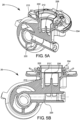
- contemplated herein is a system 10 having filter assembly 30 or 50 being shown in FIGs. 1-4 , and 6-7 along with an associated method of use.
- the systems and methods contemplated herein allow for providing a filter assembly 30 having a quantity of clean oil contained therein which allows for a quantity of contaminated or used oil to be removed from the system when the existing filter assembly is removed from a mount interface 20, wherein the contaminated oil is retained in a sealed manner within the filter assembly 30 and a new filter assembly 30, having a quantity of clean oil contained therein, is provided to the mount interface 20 so as to facilitate a drip free and simultaneous filter and partial replacement of total system oil volume.
- FIGs. 1-4 illustrate exterior views of the system 10 wherein the filter assembly 30 is attached to the mount interface 20.
- the mount interface can be provided in a plurality of orientations, and can take numerous forms.
- the mount interface shown herein is for illustrative purposes only. In some embodiments, and as discussed in more detail below, the mount interface 20 can be oriented with a horizontal contact plane, such that the filter assembly 30 attaches to a top surface.
- the filter assembly 30 can attach to the mount interface 20 using various methods, such as threaded interfaces, clamps, or locks, but as illustrated is shown as a twist lock which engages and locks over the course of an approximately 90-degree rotation.
- the filter assembly 30 can also thread onto particular components of the mount interface 20 similar to standard pre-existing oil filters presently available wherein a clean outlet can include a female threaded inner surface which mates onto a corresponding male threaded conduit which then receives filtered oil into the machinery or lubrication system.
- the mount interface 20 can include a contaminated conduit 210 and a clean conduit 220 wherein the mount interface 20 is configured to couple to an element housing 304 of the filter assembly 30.
- the filter assembly 30 can include an annular inlet 310 being provided about an end portion of the element housing as well as a clean outlet 320 being provided about a central axis of the end portion of the housing 304. It should be noted that annular inlet 310 could be arranged in a non-annular manner in other configurations and be within the scope of the invention.
- a contaminated fluid such as dirty oil
- a contaminated fluid can flow into the element housing 304 from the annular inlet 310, where it passes through contaminated side valve 450 continuing up through the interior of the element housing 304 whereupon it passes through the filter media 350 and into a central clean channel 360 formed in conduit 362 and finally through the clean valve 400 and into the clean conduit 220.
- the contaminated side valve 450 deflects upwards as pressure from the system drives contaminated oil through the housing when operational, this motion is illustrated by arrow 456, but is biased in a closed state by spring 454.
- the housing 30 can be sealed around a perimeter edge by utilizing a perimeter seal 330 which extends circumferentially around the housing and abuts against the mount interface 20.
- the perimeter of the housing can also be provided with a lock interface 334 such as angled flanges, configured to interface with one or more lock protrusions or ramps 336 provided on the mount interface 20.
- a first inner seal member 390 can be provided which is configured to seal an exterior annular portion of the inlet 212 from the perimeter seal.
- a second inner seal member 394 being configured to seal the clean outlet to a perimeter portion of the clean conduit the mount interface and which is configured to seal and separate a clean or filtered fluid exiting the clean outlet 320 into the clean conduit 220 from a contaminated fluid entering the annular inlet 310 from the contaminated conduit 210 when in an installed state about the mount interface 20;
- valve 400 and the first and second inner seals 390 and 394 respectively can be configured such that, wherein, upon removal, the valve 400 is configured to be closed prior to the release of either the first inner seal member or the second inner seal member, and wherein the first inner seal member 390 is configured to release a respective seal after the release of a second respective seal of the second inner seal member 394.
- an actuation member 226 can be provided which extends from the clean conduit 220 and is configured to extend into the clean outlet and actuate the valve 400 into an open position upon installation.
- the actuation member 226 is a protrusion that can be configured to extend into the valve body and displace an inner moveable valve body 418.
- various alternative means for automatically opening the valve upon installation and subsequent sealing upon removal may also be contemplated herein. Examples of such might include alignment of channels, using a lip or ridge portion of the inlet to press against a corresponding ledge or circumference of the valve, etc.
- a secondary contaminated side valve 450 can be provided, wherein the contaminated side valve 450 can be configured to bias in a closed position, the contaminated side valve 450 being configured to open in response to a positive pressure provided in the contaminated conduit in the installed state.
- the secondary contaminated side valve 450 can be provided with a spring 454 being configured to bias the secondary contaminated side valve 450 in a closed position such that contaminated oil does not leak back into the system or out of the filter housing when not in operation or upon removal. It will be appreciated that this valve movement can be achieved through elastic deformation, or translation of the valve components.
- the mount interface 20 can include a first annular protrusion 212; and a second annular protrusion 222.
- the first annular protrusion 212 can thus define an outer annular sidewall such that the clean conduit 220 is formed therein, i.e. between the first and second annular protrusions respectively.
- first inner seal member 390 can be configured to abut against an inner surface of the first annular protrusion 212 along a first axial distance 214 being defined as a distance between the position of the first inner seal member 390 in the installed position and the upper edge of the first annular protrusion 212 or in other words, the distance that must be traveled between an installed state and a disengaged state. Accordingly, the second inner seal member 394 can then be configured to abut against an interior portion of the second annular protrusion 222 forming a clean pathway along the central axis, wherein the second inner seal 222 is engaged along a second axial distance 224 between the installed state and a second disengaged state.
- the first axial distance 214 can be configured to be longer than the second axial distance 224 such that the second inner seal 394 is disengaged prior to the first inner seal allowing for oil contained between the contaminated side valve 450 and the inlet 210 in an intermediate state to drain into the clean conduit 220 and into space created by the axial translation of the filter housing 304 away from the clean conduit 220, thus causing a funnel effect which then reduces or eliminates any oil drips into the surrounding area or environment as all oil will drain back into the system.
- the relative heights of the second annular protrusion and the first annular protrusion can also be switched so as to cause the contaminated side to open before the clean side such that filtered oil drains into the contaminated side and is contained therein upon removal.
- the element housing can be provided with a sealed internal volume between the clean valve and the contaminated side valve in the uninstalled state, and wherein the system is provided with an initial volume of clean oil prior to installation and also is capable of transporting a portion of contaminated oil away upon removal.
- the clean valve 400 can be positioned about the clean outlet 320, the clean valve 400 can then be configured to bias in a closed position in an uninstalled state, and conversely be configured to remain open in an installed state.
- This biasing can be achieved by providing a spring 404 to the valve 400 so as to push the valve in a downward or closed position, the valve 400 being configured to translate as evidenced by arrows 406 in FIG. 4B , the downward most position being closed, and the upward position being open.
- the clean valve 400 can include an outer valve housing 414 and an inner moveable valve body 418 wherein the inner moveable valve body 418 can move axially upwardly in response to the actuation member 226.
- the inner moveable valve body 418 is pressed by the spring 404 down into a sealing grommet 410, but as it is installed, the actuation member 226 pushes the inner moveable valve body 418 within the outer valve housing 414 compressing the spring 404 and allowing fluid communication therethrough.
- the grommet 410 can be provided as an elastic or malleable material which is configured to deform and form an oil-tight seal in response to the compression force provided by the spring 404.
- the mount interface 20 can include a first annular protrusion 212; and a second annular protrusion 222.
- the first annular protrusion 212 can thus define an outer annular sidewall such that the clean conduit 220 is formed therein, i.e. between the first and second annular protrusions respectively.
- the clean conduit 362 can include a splined or fluted lower portion 368 which extends downward into the valve body 414, so as to provide a surface against which the spring 404 can press.
- the splined or fluted lower portion 368 can include a notch or seat 372 which can receive the opposing end of the spring 404 in a defined position. This splined or fluted lower portion 368 can also be configured to ensure or aide in proper alignment of the conduit 372 with the valve 400 upon assembly.
- the element housing can be provided with a sealed internal volume between the clean valve and the contaminated side valve in the uninstalled state, and wherein the system is provided with an initial volume of clean oil prior to installation and also is capable of transporting a portion of contaminated oil away upon removal.
- Also contemplated herein is a method of installing a filter assembly, the method including the steps of: providing a mount interface on a piece of equipment, the mount interface having a contaminated conduit and a clean conduit; providing a filter and mount interface as described above and the additional steps of: positioning the clean outlet of the filter assembly about the clean conduit of the mount interface; rotating the filter assembly causing an axial translation of the filter assembly into the mount interface such that the first inner seal member and the second inner seal member are engaged with the mount interface.
- the clean channel can be formed using a plurality of components so as to provide various advantages with regard to assembly and fabrication.
- the filter assembly 50 can include a similar valve 400A, a clean channel 560 which can be formed utilizing various separate, rather than unitary, parts, which can include an intermediate channel conduit 564 which can be affixed or bonded to the central clean conduit 562, and an upper seal 566 can be provided which will then sealingly engage the clean valve 400A and the intermediate channel conduit 564.
- One such advantage of having an intermediate channel conduit is a majority of the components can remain the same, while changing the length of the intermediate channel conduit and/or central clean conduit length, an increase or decrease in the total volume of oil disposed within the filter assembly can be modified.
- Additional steps can include: operating the piece of equipment so as to generate a positive pressure within the contaminated conduit and thus cause the contaminated side valve to open and permit flow therethrough; removing the filter assembly by rotating the filter assembly in an opposing direction, thus causing an opposing axial translation, wherein the opposing axial translation allows the first inner seal member and the second inner seal member to release and wherein the opposing axial translation also allows the clean valve to close.
- the filter assembly can further include various filter media 350 which can be configured to remove particulates or contaminates from the fluid stream.
- filter media 350 can be omitted altogether, wherein the housing functions as a partial oil change volume, wherein filtration can be performed at a different point in the system.
- the height of the filter housing can be varied as well as the relative diameter so as to accommodate various filtration applications as well as increase or decrease the relative volume.
- the filter housing and filter therein can be provided with no oil initially wherein a clean volume of oil can be added from an alternative fill port, wherein the removal of the filter at a service interval only functions to remove a portion of contaminated or used oil.
Landscapes
- Engineering & Computer Science (AREA)
- Chemical & Material Sciences (AREA)
- Chemical Kinetics & Catalysis (AREA)
- General Engineering & Computer Science (AREA)
- Mechanical Engineering (AREA)
- Lubrication Details And Ventilation Of Internal Combustion Engines (AREA)
- Filtration Of Liquid (AREA)
Applications Claiming Priority (2)
| Application Number | Priority Date | Filing Date | Title |
|---|---|---|---|
| US201762492273P | 2017-04-30 | 2017-04-30 | |
| PCT/EP2018/060974 WO2018202599A1 (en) | 2017-04-30 | 2018-04-27 | An oil housing, filter element, and valving assembly for providing pre-charged oil volume changes |
Publications (2)
| Publication Number | Publication Date |
|---|---|
| EP3618939A1 EP3618939A1 (en) | 2020-03-11 |
| EP3618939B1 true EP3618939B1 (en) | 2023-04-19 |
Family
ID=62143128
Family Applications (1)
| Application Number | Title | Priority Date | Filing Date |
|---|---|---|---|
| EP18723442.2A Active EP3618939B1 (en) | 2017-04-30 | 2018-04-27 | An oil housing, filter element, and valving assembly for providing pre-charged oil volume changes |
Country Status (5)
| Country | Link |
|---|---|
| US (1) | US20200191028A1 (pl) |
| EP (1) | EP3618939B1 (pl) |
| CN (1) | CN110582337B (pl) |
| PL (1) | PL3618939T3 (pl) |
| WO (1) | WO2018202599A1 (pl) |
Family Cites Families (15)
| Publication number | Priority date | Publication date | Assignee | Title |
|---|---|---|---|---|
| DE3048219A1 (de) * | 1980-12-20 | 1982-07-15 | Klöckner-Humboldt-Deutz AG, 5000 Köln | Filteraggregat fuer brennstoff oder schmieroel |
| DE19511450A1 (de) * | 1995-03-29 | 1996-10-02 | Argo Gmbh Fuer Fluidtechnik | Nebenstromfilteraggregat |
| US5569373A (en) * | 1995-06-28 | 1996-10-29 | Smith; Gerald F. | Reusable fluid filter and adapter |
| JP3653802B2 (ja) * | 1995-06-28 | 2005-06-02 | 株式会社デンソー | 内燃機関用オイルフィルタ |
| JP4117864B2 (ja) * | 1999-04-06 | 2008-07-16 | 東洋▲ろ▼機製造株式会社 | オイルフィルタの出口切換弁機構 |
| US6540914B1 (en) * | 2000-04-24 | 2003-04-01 | Vortex International, Llc | Cleanable filter with spinning screen |
| US6790356B2 (en) * | 2002-03-15 | 2004-09-14 | Arvin Technologies, Inc. | Oil filter assembly |
| JP4190383B2 (ja) * | 2003-10-01 | 2008-12-03 | トヨタ紡織株式会社 | 流体フィルタ及びそのドレン機構、流体フィルタに使用されるドレン用冶具並びに流体フィルタのドレン方法 |
| DE102004058885B4 (de) * | 2004-12-06 | 2016-12-22 | Mann + Hummel Gmbh | Füssigkeitsfilter |
| DE202007002162U1 (de) * | 2006-07-21 | 2007-12-13 | Joma-Polytec Kunststofftechnik Gmbh | Ölfilteranordnung |
| CN101505850B (zh) * | 2006-08-25 | 2013-11-20 | 曼·胡默尔有限公司 | 特别是用于汽车的液体过滤器 |
| DE202007017964U1 (de) * | 2007-12-20 | 2009-04-30 | Mann+Hummel Gmbh | Ölfilter eines Verbrennungsmotors und Filterpatrone für den Ölfilter |
| DE102011009926A1 (de) * | 2011-01-31 | 2012-08-02 | Mann + Hummel Gmbh | Filtersystem für Motoröl einer Brennkraftmaschine und Wechselfilter eines Filtersystems |
| CN106457094B (zh) * | 2014-02-27 | 2021-09-28 | Ufi过滤股份公司 | 具有固定至滤芯的水分传感器的滤筒和过滤器组件 |
| CN203990014U (zh) * | 2014-06-13 | 2014-12-10 | 上海欧菲滤清器有限公司 | 液体过滤器 |
-
2018
- 2018-04-27 PL PL18723442.2T patent/PL3618939T3/pl unknown
- 2018-04-27 CN CN201880028686.1A patent/CN110582337B/zh active Active
- 2018-04-27 EP EP18723442.2A patent/EP3618939B1/en active Active
- 2018-04-27 WO PCT/EP2018/060974 patent/WO2018202599A1/en not_active Ceased
-
2019
- 2019-10-29 US US16/667,456 patent/US20200191028A1/en not_active Abandoned
Also Published As
| Publication number | Publication date |
|---|---|
| EP3618939A1 (en) | 2020-03-11 |
| CN110582337B (zh) | 2022-03-08 |
| PL3618939T3 (pl) | 2023-08-07 |
| WO2018202599A1 (en) | 2018-11-08 |
| CN110582337A (zh) | 2019-12-17 |
| US20200191028A1 (en) | 2020-06-18 |
Similar Documents
| Publication | Publication Date | Title |
|---|---|---|
| CN201361481Y (zh) | 具有与过滤器元件协作的排放装置的筒罐式过滤器系统 | |
| JP5984817B2 (ja) | 濾過要素と協働する排水部を備えるキャニスタの濾過システム | |
| US20250196040A1 (en) | Radial seal for spin-on filter | |
| AU2009260995B2 (en) | Filter assembly | |
| US20140027366A1 (en) | Top load filter with exterior drain actuation | |
| RU2743081C2 (ru) | Запорный механизм для очистки фильтрующего элемента | |
| DE102016000157B4 (de) | Filtersystem, Verschlusselement und Filterelement | |
| CN106132504A (zh) | 卡扣到位的天然气过滤器 | |
| CN109789349B (zh) | 液体过滤器组件 | |
| US20160332095A1 (en) | Filtration System with Anti Drain Valve and Drain X-Seal | |
| US20170043285A1 (en) | Oil-filter assembly | |
| DE102010005334B4 (de) | Flüssigkeitsfilter | |
| US20200191028A1 (en) | Oil housing, filter element, and valving assembly for providing pre-charged oil volume changes | |
| EP1470847A1 (en) | Filter with check valve and assembling method thereof | |
| CN111818982B (zh) | 用于将密封构件固定在过滤器组件上的系统和方法 | |
| HK1187566B (en) | Canister filter system with drain that cooperates with filter element |
Legal Events
| Date | Code | Title | Description |
|---|---|---|---|
| STAA | Information on the status of an ep patent application or granted ep patent |
Free format text: STATUS: UNKNOWN |
|
| STAA | Information on the status of an ep patent application or granted ep patent |
Free format text: STATUS: THE INTERNATIONAL PUBLICATION HAS BEEN MADE |
|
| PUAI | Public reference made under article 153(3) epc to a published international application that has entered the european phase |
Free format text: ORIGINAL CODE: 0009012 |
|
| STAA | Information on the status of an ep patent application or granted ep patent |
Free format text: STATUS: REQUEST FOR EXAMINATION WAS MADE |
|
| 17P | Request for examination filed |
Effective date: 20191009 |
|
| AK | Designated contracting states |
Kind code of ref document: A1 Designated state(s): AL AT BE BG CH CY CZ DE DK EE ES FI FR GB GR HR HU IE IS IT LI LT LU LV MC MK MT NL NO PL PT RO RS SE SI SK SM TR |
|
| RAP3 | Party data changed (applicant data changed or rights of an application transferred) |
Owner name: MANN+HUMMEL GMBH |
|
| STAA | Information on the status of an ep patent application or granted ep patent |
Free format text: STATUS: EXAMINATION IS IN PROGRESS |
|
| 17Q | First examination report despatched |
Effective date: 20220517 |
|
| GRAP | Despatch of communication of intention to grant a patent |
Free format text: ORIGINAL CODE: EPIDOSNIGR1 |
|
| STAA | Information on the status of an ep patent application or granted ep patent |
Free format text: STATUS: GRANT OF PATENT IS INTENDED |
|
| INTG | Intention to grant announced |
Effective date: 20230104 |
|
| RIN1 | Information on inventor provided before grant (corrected) |
Inventor name: BABB, KEVIN BRIAN Inventor name: EDWARDS, PATRICK Inventor name: MARTIN, MICHAEL A. Inventor name: AHUJA, RAJAN |
|
| GRAS | Grant fee paid |
Free format text: ORIGINAL CODE: EPIDOSNIGR3 |
|
| GRAA | (expected) grant |
Free format text: ORIGINAL CODE: 0009210 |
|
| STAA | Information on the status of an ep patent application or granted ep patent |
Free format text: STATUS: THE PATENT HAS BEEN GRANTED |
|
| AK | Designated contracting states |
Kind code of ref document: B1 Designated state(s): AL AT BE BG CH CY CZ DE DK EE ES FI FR GB GR HR HU IE IS IT LI LT LU LV MC MK MT NL NO PL PT RO RS SE SI SK SM TR |
|
| REG | Reference to a national code |
Ref country code: GB Ref legal event code: FG4D |
|
| RIN1 | Information on inventor provided before grant (corrected) |
Inventor name: BABB, KEVIN BRIAN Inventor name: EDWARDS, PATRICK Inventor name: MARTIN, MICHAEL A. Inventor name: AHUJA, RAJAN |
|
| REG | Reference to a national code |
Ref country code: CH Ref legal event code: EP |
|
| REG | Reference to a national code |
Ref country code: DE Ref legal event code: R096 Ref document number: 602018048568 Country of ref document: DE |
|
| REG | Reference to a national code |
Ref country code: IE Ref legal event code: FG4D |
|
| REG | Reference to a national code |
Ref country code: AT Ref legal event code: REF Ref document number: 1560783 Country of ref document: AT Kind code of ref document: T Effective date: 20230515 |
|
| P01 | Opt-out of the competence of the unified patent court (upc) registered |
Effective date: 20230627 |
|
| REG | Reference to a national code |
Ref country code: LT Ref legal event code: MG9D |
|
| REG | Reference to a national code |
Ref country code: NL Ref legal event code: MP Effective date: 20230419 |
|
| PG25 | Lapsed in a contracting state [announced via postgrant information from national office to epo] |
Ref country code: NL Free format text: LAPSE BECAUSE OF FAILURE TO SUBMIT A TRANSLATION OF THE DESCRIPTION OR TO PAY THE FEE WITHIN THE PRESCRIBED TIME-LIMIT Effective date: 20230419 |
|
| PG25 | Lapsed in a contracting state [announced via postgrant information from national office to epo] |
Ref country code: SE Free format text: LAPSE BECAUSE OF FAILURE TO SUBMIT A TRANSLATION OF THE DESCRIPTION OR TO PAY THE FEE WITHIN THE PRESCRIBED TIME-LIMIT Effective date: 20230419 Ref country code: PT Free format text: LAPSE BECAUSE OF FAILURE TO SUBMIT A TRANSLATION OF THE DESCRIPTION OR TO PAY THE FEE WITHIN THE PRESCRIBED TIME-LIMIT Effective date: 20230821 Ref country code: NO Free format text: LAPSE BECAUSE OF FAILURE TO SUBMIT A TRANSLATION OF THE DESCRIPTION OR TO PAY THE FEE WITHIN THE PRESCRIBED TIME-LIMIT Effective date: 20230719 Ref country code: ES Free format text: LAPSE BECAUSE OF FAILURE TO SUBMIT A TRANSLATION OF THE DESCRIPTION OR TO PAY THE FEE WITHIN THE PRESCRIBED TIME-LIMIT Effective date: 20230419 |
|
| PG25 | Lapsed in a contracting state [announced via postgrant information from national office to epo] |
Ref country code: RS Free format text: LAPSE BECAUSE OF FAILURE TO SUBMIT A TRANSLATION OF THE DESCRIPTION OR TO PAY THE FEE WITHIN THE PRESCRIBED TIME-LIMIT Effective date: 20230419 Ref country code: LV Free format text: LAPSE BECAUSE OF FAILURE TO SUBMIT A TRANSLATION OF THE DESCRIPTION OR TO PAY THE FEE WITHIN THE PRESCRIBED TIME-LIMIT Effective date: 20230419 Ref country code: LT Free format text: LAPSE BECAUSE OF FAILURE TO SUBMIT A TRANSLATION OF THE DESCRIPTION OR TO PAY THE FEE WITHIN THE PRESCRIBED TIME-LIMIT Effective date: 20230419 Ref country code: IS Free format text: LAPSE BECAUSE OF FAILURE TO SUBMIT A TRANSLATION OF THE DESCRIPTION OR TO PAY THE FEE WITHIN THE PRESCRIBED TIME-LIMIT Effective date: 20230819 Ref country code: HR Free format text: LAPSE BECAUSE OF FAILURE TO SUBMIT A TRANSLATION OF THE DESCRIPTION OR TO PAY THE FEE WITHIN THE PRESCRIBED TIME-LIMIT Effective date: 20230419 Ref country code: GR Free format text: LAPSE BECAUSE OF FAILURE TO SUBMIT A TRANSLATION OF THE DESCRIPTION OR TO PAY THE FEE WITHIN THE PRESCRIBED TIME-LIMIT Effective date: 20230720 Ref country code: AL Free format text: LAPSE BECAUSE OF FAILURE TO SUBMIT A TRANSLATION OF THE DESCRIPTION OR TO PAY THE FEE WITHIN THE PRESCRIBED TIME-LIMIT Effective date: 20230419 |
|
| REG | Reference to a national code |
Ref country code: CH Ref legal event code: PL |
|
| PG25 | Lapsed in a contracting state [announced via postgrant information from national office to epo] |
Ref country code: LU Free format text: LAPSE BECAUSE OF NON-PAYMENT OF DUE FEES Effective date: 20230427 Ref country code: FI Free format text: LAPSE BECAUSE OF FAILURE TO SUBMIT A TRANSLATION OF THE DESCRIPTION OR TO PAY THE FEE WITHIN THE PRESCRIBED TIME-LIMIT Effective date: 20230419 |
|
| REG | Reference to a national code |
Ref country code: BE Ref legal event code: MM Effective date: 20230430 |
|
| PG25 | Lapsed in a contracting state [announced via postgrant information from national office to epo] |
Ref country code: SK Free format text: LAPSE BECAUSE OF FAILURE TO SUBMIT A TRANSLATION OF THE DESCRIPTION OR TO PAY THE FEE WITHIN THE PRESCRIBED TIME-LIMIT Effective date: 20230419 |
|
| PG25 | Lapsed in a contracting state [announced via postgrant information from national office to epo] |
Ref country code: MC Free format text: LAPSE BECAUSE OF FAILURE TO SUBMIT A TRANSLATION OF THE DESCRIPTION OR TO PAY THE FEE WITHIN THE PRESCRIBED TIME-LIMIT Effective date: 20230419 |
|
| REG | Reference to a national code |
Ref country code: DE Ref legal event code: R097 Ref document number: 602018048568 Country of ref document: DE |
|
| PG25 | Lapsed in a contracting state [announced via postgrant information from national office to epo] |
Ref country code: SM Free format text: LAPSE BECAUSE OF FAILURE TO SUBMIT A TRANSLATION OF THE DESCRIPTION OR TO PAY THE FEE WITHIN THE PRESCRIBED TIME-LIMIT Effective date: 20230419 Ref country code: SK Free format text: LAPSE BECAUSE OF FAILURE TO SUBMIT A TRANSLATION OF THE DESCRIPTION OR TO PAY THE FEE WITHIN THE PRESCRIBED TIME-LIMIT Effective date: 20230419 Ref country code: RO Free format text: LAPSE BECAUSE OF FAILURE TO SUBMIT A TRANSLATION OF THE DESCRIPTION OR TO PAY THE FEE WITHIN THE PRESCRIBED TIME-LIMIT Effective date: 20230419 Ref country code: MC Free format text: LAPSE BECAUSE OF FAILURE TO SUBMIT A TRANSLATION OF THE DESCRIPTION OR TO PAY THE FEE WITHIN THE PRESCRIBED TIME-LIMIT Effective date: 20230419 Ref country code: LI Free format text: LAPSE BECAUSE OF NON-PAYMENT OF DUE FEES Effective date: 20230430 Ref country code: EE Free format text: LAPSE BECAUSE OF FAILURE TO SUBMIT A TRANSLATION OF THE DESCRIPTION OR TO PAY THE FEE WITHIN THE PRESCRIBED TIME-LIMIT Effective date: 20230419 Ref country code: DK Free format text: LAPSE BECAUSE OF FAILURE TO SUBMIT A TRANSLATION OF THE DESCRIPTION OR TO PAY THE FEE WITHIN THE PRESCRIBED TIME-LIMIT Effective date: 20230419 Ref country code: CZ Free format text: LAPSE BECAUSE OF FAILURE TO SUBMIT A TRANSLATION OF THE DESCRIPTION OR TO PAY THE FEE WITHIN THE PRESCRIBED TIME-LIMIT Effective date: 20230419 Ref country code: CH Free format text: LAPSE BECAUSE OF NON-PAYMENT OF DUE FEES Effective date: 20230430 |
|
| REG | Reference to a national code |
Ref country code: IE Ref legal event code: MM4A |
|
| PLBE | No opposition filed within time limit |
Free format text: ORIGINAL CODE: 0009261 |
|
| STAA | Information on the status of an ep patent application or granted ep patent |
Free format text: STATUS: NO OPPOSITION FILED WITHIN TIME LIMIT |
|
| PG25 | Lapsed in a contracting state [announced via postgrant information from national office to epo] |
Ref country code: BE Free format text: LAPSE BECAUSE OF NON-PAYMENT OF DUE FEES Effective date: 20230430 |
|
| 26N | No opposition filed |
Effective date: 20240122 |
|
| PG25 | Lapsed in a contracting state [announced via postgrant information from national office to epo] |
Ref country code: IE Free format text: LAPSE BECAUSE OF NON-PAYMENT OF DUE FEES Effective date: 20230427 |
|
| PG25 | Lapsed in a contracting state [announced via postgrant information from national office to epo] |
Ref country code: IE Free format text: LAPSE BECAUSE OF NON-PAYMENT OF DUE FEES Effective date: 20230427 |
|
| PG25 | Lapsed in a contracting state [announced via postgrant information from national office to epo] |
Ref country code: SI Free format text: LAPSE BECAUSE OF FAILURE TO SUBMIT A TRANSLATION OF THE DESCRIPTION OR TO PAY THE FEE WITHIN THE PRESCRIBED TIME-LIMIT Effective date: 20230419 |
|
| PG25 | Lapsed in a contracting state [announced via postgrant information from national office to epo] |
Ref country code: SI Free format text: LAPSE BECAUSE OF FAILURE TO SUBMIT A TRANSLATION OF THE DESCRIPTION OR TO PAY THE FEE WITHIN THE PRESCRIBED TIME-LIMIT Effective date: 20230419 Ref country code: IT Free format text: LAPSE BECAUSE OF FAILURE TO SUBMIT A TRANSLATION OF THE DESCRIPTION OR TO PAY THE FEE WITHIN THE PRESCRIBED TIME-LIMIT Effective date: 20230419 Ref country code: FR Free format text: LAPSE BECAUSE OF NON-PAYMENT OF DUE FEES Effective date: 20230619 |
|
| PGFP | Annual fee paid to national office [announced via postgrant information from national office to epo] |
Ref country code: DE Payment date: 20250422 Year of fee payment: 8 Ref country code: PL Payment date: 20250417 Year of fee payment: 8 |
|
| PGFP | Annual fee paid to national office [announced via postgrant information from national office to epo] |
Ref country code: GB Payment date: 20250423 Year of fee payment: 8 |
|
| PGFP | Annual fee paid to national office [announced via postgrant information from national office to epo] |
Ref country code: BG Payment date: 20250424 Year of fee payment: 8 |
|
| PGFP | Annual fee paid to national office [announced via postgrant information from national office to epo] |
Ref country code: AT Payment date: 20250423 Year of fee payment: 8 |
|
| PG25 | Lapsed in a contracting state [announced via postgrant information from national office to epo] |
Ref country code: CY Free format text: LAPSE BECAUSE OF FAILURE TO SUBMIT A TRANSLATION OF THE DESCRIPTION OR TO PAY THE FEE WITHIN THE PRESCRIBED TIME-LIMIT; INVALID AB INITIO Effective date: 20180427 |
|
| PG25 | Lapsed in a contracting state [announced via postgrant information from national office to epo] |
Ref country code: HU Free format text: LAPSE BECAUSE OF FAILURE TO SUBMIT A TRANSLATION OF THE DESCRIPTION OR TO PAY THE FEE WITHIN THE PRESCRIBED TIME-LIMIT; INVALID AB INITIO Effective date: 20180427 |
|
| REG | Reference to a national code |
Ref country code: AT Ref legal event code: UEP Ref document number: 1560783 Country of ref document: AT Kind code of ref document: T Effective date: 20230419 |
|
| PG25 | Lapsed in a contracting state [announced via postgrant information from national office to epo] |
Ref country code: TR Free format text: LAPSE BECAUSE OF FAILURE TO SUBMIT A TRANSLATION OF THE DESCRIPTION OR TO PAY THE FEE WITHIN THE PRESCRIBED TIME-LIMIT Effective date: 20230419 |