EP3618292A1 - System and method for establishing an intervehicle communication - Google Patents
System and method for establishing an intervehicle communication Download PDFInfo
- Publication number
- EP3618292A1 EP3618292A1 EP18192102.4A EP18192102A EP3618292A1 EP 3618292 A1 EP3618292 A1 EP 3618292A1 EP 18192102 A EP18192102 A EP 18192102A EP 3618292 A1 EP3618292 A1 EP 3618292A1
- Authority
- EP
- European Patent Office
- Prior art keywords
- message
- communication
- lines
- over
- establishing
- Prior art date
- Legal status (The legal status is an assumption and is not a legal conclusion. Google has not performed a legal analysis and makes no representation as to the accuracy of the status listed.)
- Granted
Links
Images
Classifications
-
- H—ELECTRICITY
- H04—ELECTRIC COMMUNICATION TECHNIQUE
- H04B—TRANSMISSION
- H04B3/00—Line transmission systems
- H04B3/54—Systems for transmission via power distribution lines
- H04B3/548—Systems for transmission via power distribution lines the power on the line being DC
-
- H—ELECTRICITY
- H04—ELECTRIC COMMUNICATION TECHNIQUE
- H04B—TRANSMISSION
- H04B1/00—Details of transmission systems, not covered by a single one of groups H04B3/00 - H04B13/00; Details of transmission systems not characterised by the medium used for transmission
- H04B1/74—Details of transmission systems, not covered by a single one of groups H04B3/00 - H04B13/00; Details of transmission systems not characterised by the medium used for transmission for increasing reliability, e.g. using redundant or spare channels or apparatus
-
- H—ELECTRICITY
- H04—ELECTRIC COMMUNICATION TECHNIQUE
- H04W—WIRELESS COMMUNICATION NETWORKS
- H04W76/00—Connection management
- H04W76/10—Connection setup
-
- B—PERFORMING OPERATIONS; TRANSPORTING
- B61—RAILWAYS
- B61L—GUIDING RAILWAY TRAFFIC; ENSURING THE SAFETY OF RAILWAY TRAFFIC
- B61L27/00—Central railway traffic control systems; Trackside control; Communication systems specially adapted therefor
Definitions
- the present invention relates to a system and method for establishing an intervehicle communication for at least a first and a second commercial vehicle.
- E.g. weather and military radars can temporarily block wireless communication channels in the 5GHz UNII bands, misbehaving high power device in close proximity can radiate disturbing signals or intentional harmful radiation can cause temporary outage in the targeted frequencies.
- This invention deals with redundant communication solution which makes it possible to maintain communication even if some of the communication links are temporarily down.
- AU 2012 101 599 A4 discloses a wireless trailer brake control system for communicating braking information between a tow vehicle and a trailer using wireless communication, wherein the trailer control module is communicatively coupled to the trailer brake system of the trailer.
- the trailer control module is communicatively coupled to the trailer brake system of the trailer.
- US 2017/0217372 A1 relates to a vision system where a camera is placed onto the trailer, the camera picture is transmitted wirelessly to the towing vehicle and the camera picture is presented on a screen in the towing vehicle.
- This prior art relates to camera picture transmission solely and does not take reliability and redundancy into account.
- a system for establishing an intervehicle communication comprising several wireless and/or wired and/or physical communication lines, further comprising at least one message sending module and at least one message receiving module, wherein the message sending module is configured and arranged to send the at least one message over one or more lines and wherein the message receiving module is configured to receive the message over one or more lines.
- the invention is based on the basic idea that an intervehicle communication system is provided between vehicles in combination, in the field of commercial vehicles, e.g. such a combination can be a truck-trailer or a trailer-trailer in case of a road train scenario.
- the architecture shall contain multiple communication lines or links.
- the data or messages can be transferred over more than one communication links.
- the transmission of a message over the links can be simultaneously or can work in a warm backup manner. If one link fails, e.g. the quality of service drops below certain level, the backup immediately takes over the communication.
- Any of the redundant physical communication links can be wired or wireless. With such a redundancy provided, the reliability and availability of the intervehicle communication against unintentional or intentional disturbances can be significantly increased.
- the system can further comprise at least one message transmission quality monitoring module, which is configured and arranged to monitor and/or assess the transmission quality of a message sent from the message sending module to the message receiving module.
- at least one message transmission quality monitoring module which is configured and arranged to monitor and/or assess the transmission quality of a message sent from the message sending module to the message receiving module.
- the message transmission quality monitoring module is configured and arranged to trigger an additional transmission of the message over one or more lines when a quality drop of transmission is detected.
- At least two communication lines are non-overlapping wireless channels.
- disturbances or noise within one channel is not effecting the other wireless channel. Consequently, a higher level of transmission security is reached.
- the wireless channels may not be closer to each other than 50 MHz. If so, the channels have sufficient distance in frequencies between each other. Thus, the overall system may be more reliable and stayable as it is less vulnerable against disturbances.
- the communication over at least one of the wireless lines is in conformity with at least one of the standards WiFi, Bluetooth, WAVE, ETSI ITS-G5, IEEE 802.15.4, C-V2X or the like.
- the present invention relates to a method for establishing an intervehicle communication. Accordingly, the method for establishing an intervehicle communication comprising at least the following steps:
- the message may be sent over at least two communication lines simultaneously.
- the message may be sent over at least two communication lines, wherein the second line is used in case that the first line is temporarily not in operation and/or the transmission quality is lowered and/or the transmission of the first line is corrupted.
- the method may be performed by using the system according to the system as described above.
- the present invention relates to a message sending module for a system for establishing an intervehicle communication.
- the message sending module comprises the features of the message sending module as described in this disclosure.
- the message sending module may be a transceiver.
- the message sending module comprises a redundant sending capability, i.e. at least two sending elements being capable to transmit data and/or information, especially over the communication line to a message receiving module.
- the message sending module can be capable to send or transmit messages over the two wireless channels. It may also comprise the capability for sending of messages over at least one wireless and at least one wired and/or physical line.
- the present invention relates to a message receiving module for a system for establishing an intervehicle communication.
- the message receiving module comprises the features of the message receiving module as described in this disclosure.
- the message receiving module may be a transceiver.
- the message receiving module comprises a redundant receiving capability, i.e. at least two receiving elements being capable to receive data and/or information, especially over the communication line to a message sending module.
- the message receiving module can be capable to receive messages over the two wireless channels. It may also comprise the capability for receiving of messages over at least one wireless and at least one wired and/or physical line.
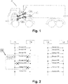
- Fig. 1 shows a schematical drawing commercial vehicle with the vehicle combination comprising a truck 5 and a trailer 7 equipped with a system 10 for establishing an intervehicle communication for at least a first and a second commercial vehicle, here between the truck 5 and the trailer 7.
- the tethered vehicles are the truck 5 and the trailer 7.
- the tethered vehicles are a first trailer and a second trailer, e.g. in the scenario of a road train.
- the tethered vehicles could be the truck, the first trailer and the second trailer.
- Both vehicles have at least one communication ECU 13, 14.
- the ECU 13 is the ECU of the trailer 7 and the ECU 14 is the ECU of the truck 5.
- Both ECU 13, 14 are equipped with two or more communication links 11, 12.
- the communication links 11, 12 may be wired or may be wireless. In the shown embodiment, the communication links 11, 12 are wireless.
- the communication links 11, 12 are WiFi-connections.
- the ECU 13 of the trailer has two respective transceivers 11 B and 12B and the ECU 14 of the truck 5 has corresponding transceivers 11A and 12A.
- the transceivers 11A, 11B and 12A, 12B form the message sending modules and message receiving modules of the system.
- transceivers 11A, 11B and 12A, 12B are capable to send and receive, they form a module with integrated message sending and message receiving capability. Thus, they are at the same time a message sending module and a message receiving module and they are configured and arranged to send messages over one or more communication links/lines 11, 12 and they are configured to receive messages over one or more communication links/lines 11, 12.
- the two or more WiFi channels/WiFi connections 11, 12 are far enough from each other in terms of frequency.
- the communication over at least one of the wireless lines can in conformity with at least one of the standards Bluetooth, WAVE, ETSI ITS-G5, IEEE 802.15.4, C-V2X or the like.
- a possible combination could be the use of Bluetooth additionally to the WiFi standard. So, one communication link could be a WiFi-link and another communication link could be a Bluetooth link.
- first standard for a first link and a second standard for the second link, wherein the second standard is different from the standard used for the first link.
- They may be arranged and configured as non-overlapping wireless channels 11, 12.
- the wireless channels 11, 12 can be chosen such that they are no closer to each other than 50 MHz.
- one of the connections 11, 12 may be a WiFi link in the 5GHz range and the other connection may be a Bluetooth link in the 2.4GHz range.
- the system 10 further comprises at least one message transmission quality monitoring module 15.
- the message transmission quality monitoring module 15 is configured and arranged to monitor and/or assess the transmission quality of a message sent from the message sending module 11A, 11B, 12A, 12B to the message receiving module 11A, 11B, 12A, 12B.
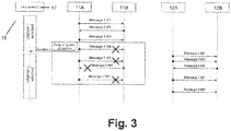
- the data in form of messages M1, M2, M3, M4, M5, M6, M7 or M8 travel simultaneously over the communication link 11 from transceiver 11A to transceiver 11B and vice versa.
- the same messages M1, M2, M3, M4, M5, M6, M7 or M8 travel simultaneously over the other communication link 12 from transceiver 12A to transceiver 12B and vice versa.
- Such a drop of quality of service is detected by the message transmission quality monitoring module 15.
- This module is measuring continuously the quality of service of the data or message transmission in the communication links 11, 12.
- the second channel or communication link 12 remains active and undisturbed and thus allows continuous communication.
- communications links 11 and 12 are provided.
- the non-active link is the communication link 12 between the transceivers 12A and 12B.
- the communication link 12 between the transceivers 12A and 12B stays in a warm back-up state, ready for taking over communication when it is needed. This is e.g. the case, when there is a drop of quality of service between communication link 11 between the transceivers 11A and 11B.
- the drop of service as shown in Fig. 3 affects the transmittal of messages M4 to M7.
- a link selector logic 17 is needed to be implemented on both vehicles, here the truck 5 and the trailer 7.
- the link selector logic 17 can be part of the message transmission quality monitoring module 15.
- the link selector logic 15 needs to be capable of determining when the quality of service of the active communication link drops below a threshold level.
- the message transmission quality monitoring module 15 is configured and arranged to trigger an additional transmission of the message over one or more lines, i.e. the communication links 11, 12 when a quality drop of transmission is detected.
Landscapes
- Engineering & Computer Science (AREA)
- Computer Networks & Wireless Communication (AREA)
- Signal Processing (AREA)
- Power Engineering (AREA)
- Mobile Radio Communication Systems (AREA)
Abstract
Description
- The present invention relates to a system and method for establishing an intervehicle communication for at least a first and a second commercial vehicle.
- Between the truck, trailer and multiple trailers wired communication interfaces (e.g. defined by the ISO 11992 standards) are widely used in the field of commercial vehicles. Especially with the rise of autonomous vehicles the need emerges to more reliably transmit significantly more amount of data. To support these signals new communication solutions emerge, some using wireless communication interfaces.
- An issue with the current communication solutions is that they all rely on a single physical link. If that link gets corrupted, all layers of the communication above get corrupted as well. When it comes to wireless solutions this issue is elevated, since even sources out of the vehicle can have harmful effects to the communication.
- E.g. weather and military radars can temporarily block wireless communication channels in the 5GHz UNII bands, misbehaving high power device in close proximity can radiate disturbing signals or intentional harmful radiation can cause temporary outage in the targeted frequencies.
- This invention deals with redundant communication solution which makes it possible to maintain communication even if some of the communication links are temporarily down.
-
DE 10 2015 212 951 A1 discloses an in-vehicle communication system having two parallel communication paths of sending the messages via either the first or the second communication path. This patent describes an intra-vehicle communication. -
AU 2012 101 599 A4 -
US 2017/0217372 A1 relates to a vision system where a camera is placed onto the trailer, the camera picture is transmitted wirelessly to the towing vehicle and the camera picture is presented on a screen in the towing vehicle. This prior art relates to camera picture transmission solely and does not take reliability and redundancy into account. - It is the object of the present invention to provide the system and a method for establishing an intervehicle communication for at least a first and a second commercial vehicle, in particular in that the reliability and redundancy of signal and information transmission in the intervehicle communication is enhanced and more reliability and redundancy is provided.
- This object is solved by a system for establishing an intervehicle communication with the features of
claim 1. Accordingly, a system for establishing an intervehicle communication for at least a first and a second commercial vehicle is provided, comprising several wireless and/or wired and/or physical communication lines, further comprising at least one message sending module and at least one message receiving module, wherein the message sending module is configured and arranged to send the at least one message over one or more lines and wherein the message receiving module is configured to receive the message over one or more lines. - The invention is based on the basic idea that an intervehicle communication system is provided between vehicles in combination, in the field of commercial vehicles, e.g. such a combination can be a truck-trailer or a trailer-trailer in case of a road train scenario. The architecture shall contain multiple communication lines or links. The data or messages can be transferred over more than one communication links. The transmission of a message over the links can be simultaneously or can work in a warm backup manner. If one link fails, e.g. the quality of service drops below certain level, the backup immediately takes over the communication. Any of the redundant physical communication links can be wired or wireless. With such a redundancy provided, the reliability and availability of the intervehicle communication against unintentional or intentional disturbances can be significantly increased.
- The system can further comprise at least one message transmission quality monitoring module, which is configured and arranged to monitor and/or assess the transmission quality of a message sent from the message sending module to the message receiving module. By monitoring the transmission quality it is possible for the system to find out, whether the message transmission quality is sufficient for stable and reliable communication. If it is found that the quality is below a threshold value, then specific counter measures may be triggered by such an event.
- In particular, the message transmission quality monitoring module is configured and arranged to trigger an additional transmission of the message over one or more lines when a quality drop of transmission is detected. By this, it can be ensured that the necessary data transmission or communication is done, even in case that there is a quality drop in the transmission and that there are disturbances in signal transmission.
- Furthermore, it is possible that at least two communication lines are non-overlapping wireless channels. By such a choice of wireless channels disturbances or noise within one channel is not effecting the other wireless channel. Consequently, a higher level of transmission security is reached.
- The wireless channels may not be closer to each other than 50 MHz. If so, the channels have sufficient distance in frequencies between each other. Thus, the overall system may be more reliable and stayable as it is less vulnerable against disturbances.
- Furthermore, it is possible that the communication over at least one of the wireless lines is in conformity with at least one of the standards WiFi, Bluetooth, WAVE, ETSI ITS-G5, IEEE 802.15.4, C-V2X or the like. By using one of these standards a simplified implementation of such communication lines is possible. In particular, no own standard must be established. Also standard elements may be used and compatibility with other networks is possible.
- Additionally, the present invention relates to a method for establishing an intervehicle communication. Accordingly, the method for establishing an intervehicle communication comprising at least the following steps:
- Providing several wireless and/or wired and/or physical communication lines;
- send the at least one message over one or more lines; and
- receive the message over one or more lines.
- The message may be sent over at least two communication lines simultaneously.
- Also, the message may be sent over at least two communication lines, wherein the second line is used in case that the first line is temporarily not in operation and/or the transmission quality is lowered and/or the transmission of the first line is corrupted.
- Also, the method may be performed by using the system according to the system as described above.
- Furthermore, the present invention relates to a message sending module for a system for establishing an intervehicle communication. The message sending module comprises the features of the message sending module as described in this disclosure. In particular, the message sending module may be a transceiver. Also, it is possible that the message sending module comprises a redundant sending capability, i.e. at least two sending elements being capable to transmit data and/or information, especially over the communication line to a message receiving module. For example, the message sending module can be capable to send or transmit messages over the two wireless channels. It may also comprise the capability for sending of messages over at least one wireless and at least one wired and/or physical line.
- Additionally, the present invention relates to a message receiving module for a system for establishing an intervehicle communication. The message receiving module comprises the features of the message receiving module as described in this disclosure. In particular, the message receiving module may be a transceiver. Also, it is possible that the message receiving module comprises a redundant receiving capability, i.e. at least two receiving elements being capable to receive data and/or information, especially over the communication line to a message sending module. For example, the message receiving module can be capable to receive messages over the two wireless channels. It may also comprise the capability for receiving of messages over at least one wireless and at least one wired and/or physical line.
- Further details and advantages shall now be described in connection with the figures.
- It is shown in
- Fig. 1
- a schematical drawing of a commercial vehicle with the vehicle combination comprising a truck and a trailer in a block diagram of the intervehicle communication equipped with a system for establishing an intervehicle communication for at least a first and a second commercial vehicle according to an embodiment of the present invention;
- Fig. 2
- a time diagram of simultaneous messaging; and
- Fig. 3
- a time diagram of redundant communication in warm backup messaging
-
Fig. 1 shows a schematical drawing commercial vehicle with the vehicle combination comprising atruck 5 and atrailer 7 equipped with asystem 10 for establishing an intervehicle communication for at least a first and a second commercial vehicle, here between thetruck 5 and thetrailer 7. - In this embodiment the tethered vehicles are the
truck 5 and thetrailer 7. - Generally speaking, it would be also possible that the tethered vehicles are a first trailer and a second trailer, e.g. in the scenario of a road train. In such a scenario, the tethered vehicles could be the truck, the first trailer and the second trailer.
- Both vehicles have at least one
communication ECU - The
ECU 13 is the ECU of thetrailer 7 and theECU 14 is the ECU of thetruck 5. - Both
ECU more communication links - The communication links 11, 12 may be wired or may be wireless. In the shown embodiment, the communication links 11, 12 are wireless.
- Also a physical communication link of any suitable kind could be used.
- Here, the communication links 11, 12 are WiFi-connections.
- The
ECU 13 of the trailer has tworespective transceivers ECU 14 of thetruck 5 has correspondingtransceivers - The
transceivers - As the
transceivers lines lines - The two or more WiFi channels/
WiFi connections - As an alternative to WiFi, the communication over at least one of the wireless lines can in conformity with at least one of the standards Bluetooth, WAVE, ETSI ITS-G5, IEEE 802.15.4, C-V2X or the like.
- A possible combination could be the use of Bluetooth additionally to the WiFi standard. So, one communication link could be a WiFi-link and another communication link could be a Bluetooth link.
- Generally, it could be possible to use a first standard for a first link and a second standard for the second link, wherein the second standard is different from the standard used for the first link.
- They may be arranged and configured as
non-overlapping wireless channels - Thus, it is unlikely that the same source of disturbance harms both of them.
- For example, the
wireless channels - Alternatively, one of the
connections - The
system 10 further comprises at least one message transmissionquality monitoring module 15. - The message transmission
quality monitoring module 15 is configured and arranged to monitor and/or assess the transmission quality of a message sent from themessage sending module message receiving module - In one embodiment as shown in
Fig. 2 the data in form of messages M1, M2, M3, M4, M5, M6, M7 or M8 travel simultaneously over thecommunication link 11 fromtransceiver 11A totransceiver 11B and vice versa. - At the same time, the same messages M1, M2, M3, M4, M5, M6, M7 or M8 travel simultaneously over the other communication link 12 from
transceiver 12A totransceiver 12B and vice versa. - If one of the communication links gets corrupted, as it is the case for the sent messages M4 to M7 in the
communication link 11, even if that corruption is only temporary (here shown in case of a drop of quality of service of a certain, short amount of time) theother communication link 12 is still functional and therefore capable of transmitting data. - Such a drop of quality of service is detected by the message transmission
quality monitoring module 15. - This module is measuring continuously the quality of service of the data or message transmission in the communication links 11, 12.
- Consequently, the messages M4 to M7 will be sent and received correctly and even in such a case the intervehicle communication remains still active and can operate.
- Here, the second channel or
communication link 12 remains active and undisturbed and thus allows continuous communication. - In another embodiment as shown in
Fig. 3 , not all the communication links are continuously active. - In this embodiment, all structural and functional features of the
system 3 as shown inFig. 1 are present and realized. - Only the following differences are present and will be described below:
Here communications links 11 and 12 are provided. - The non-active link is the
communication link 12 between thetransceivers - The
communication link 12 between thetransceivers communication link 11 between thetransceivers - The drop of service as shown in
Fig. 3 affects the transmittal of messages M4 to M7. - To accomplish this, a
link selector logic 17 is needed to be implemented on both vehicles, here thetruck 5 and thetrailer 7. - The
link selector logic 17 can be part of the message transmissionquality monitoring module 15. - The
link selector logic 15 needs to be capable of determining when the quality of service of the active communication link drops below a threshold level. An advantage of such a solution is the more efficient use of spectrum in case of wireless links. - So, the message transmission
quality monitoring module 15 is configured and arranged to trigger an additional transmission of the message over one or more lines, i.e. the communication links 11, 12 when a quality drop of transmission is detected. -
- 5
- Truck
- 7
- Trailer
- 10
- System for establishing an intervehicle communication
- 11
- Communication line, communication link
- 12
- Communication line, communication link
- 11A
- Transceiver
- 11B
- Transceiver
- 12A
- Transceiver
- 12B
- Transceiver
- 13
- Electronic control unit (ECU)
- 14
- Electronic control unit (ECU)
- 15
- Message transmission quality monitoring module
- 17
- Link selector logic
- M1
-
Message 1 - M2
-
Message 2 - M3
-
Message 3 - M4
-
Message 4 - M5
-
Message 5 - M6
-
Message 6 - M7
-
Message 7 - M8
-
Message 8
Claims (12)
- A system (10) for establishing an intervehicle communication for at least a first and a second commercial vehicle (5, 7), comprising several wireless and/or wired and/or physical communication lines (11, 12), further comprising at least one message sending module (11A, 11B, 12A, 12B) and at least one message receiving module (11A, 11B, 12A, 12B), wherein the message sending module (11A, 11B, 12A, 12B) is configured and arranged to send the at least one message over one or more lines and wherein the message receiving module (11A, 11B, 12A, 12B) is configured to receive the message over one or more lines (11, 12).
- The system (10) according to claim 1,
characterized in that
the system (10) further comprises at least one message transmission quality monitoring module (15), which is configured and arranged to monitor and/or assess the transmission quality of a message sent from the message sending module (11A, 11B, 12A, 12B) to the message receiving module (11A, 11B, 12A, 12B). - The system (10) according to claim 2,
characterized in that
the message transmission quality monitoring module (15) is configured and arranged to trigger an additional transmission of the message over one or more lines (11, 12) when a quality drop of transmission is detected. - The system (10) according to one of the preceding claims,
characterized in that
at least two of communication lines (11, 12) are non-overlapping wireless channels. - The system (10) according to claim 4,
characterized in that
the wireless channels (11, 12) are no closer to each other than 50 MHz. - The system (10) according to one of the preceding claims,
characterized in that
the communication over at least one of the wireless lines is in conformity with at least one of the standards WiFi, Bluetooth, WAVE, ETSI ITS-G5, IEEE 802.15.4, C-V2X or the like. - A method for establishing an intervehicle communication for at least a first and a second commercial vehicle (5, 7), comprising at least the following steps:- Providing several wireless and/or wired communication lines (11, 12);- send the at least one message over one or more lines (11, 12); and- receive the message over one or more lines (11, 12).
- The method according to claim 7,
characterized in that
the message is sent over at least two communication lines (11, 12) simultaneously. - The method according to claim 7,
characterized in that
the message is sent over at least two communication lines (11, 12), wherein the second line (12) is use in case that the first line (11) is temporarily not in operation and/or the transmission quality is lowered and/or the transmission of the first line (11) is corrupted. - The method according to one of claims 7 to 9,
characterized in that
the method is performed by using the system (10) according to one of claims 1 to 6. - A message sending module (11A, 11B, 12A, 12B) for a system (10) for establishing an intervehicle communication according to one of claims 1 to 6, comprising the features of the message sending module (11A, 11B, 12A, 12B).
- A message receiving module (11A, 11B, 12A, 12B) for a system (10) for establishing an intervehicle communication according to one of claims 1 to 6, comprising the features of the message receiving module (11A, 11B, 12A, 12B).
Priority Applications (6)
| Application Number | Priority Date | Filing Date | Title |
|---|---|---|---|
| PL18192102.4T PL3618292T3 (en) | 2018-08-31 | 2018-08-31 | System and method for establishing an intervehicle communication |
| EP18192102.4A EP3618292B1 (en) | 2018-08-31 | 2018-08-31 | System and method for establishing an intervehicle communication |
| PCT/EP2019/070429 WO2020043412A1 (en) | 2018-08-31 | 2019-07-30 | System and method for establishing and intervehicle communication |
| JP2021510778A JP7317948B2 (en) | 2018-08-31 | 2019-07-30 | Systems and methods for establishing inter-vehicle communication |
| US17/272,453 US11894871B2 (en) | 2018-08-31 | 2019-07-30 | System and method for establishing an intervehicle communication |
| CN201980056492.7A CN112640319A (en) | 2018-08-31 | 2019-07-30 | System and method for establishing inter-vehicle communication |
Applications Claiming Priority (1)
| Application Number | Priority Date | Filing Date | Title |
|---|---|---|---|
| EP18192102.4A EP3618292B1 (en) | 2018-08-31 | 2018-08-31 | System and method for establishing an intervehicle communication |
Publications (2)
| Publication Number | Publication Date |
|---|---|
| EP3618292A1 true EP3618292A1 (en) | 2020-03-04 |
| EP3618292B1 EP3618292B1 (en) | 2023-12-06 |
Family
ID=63490248
Family Applications (1)
| Application Number | Title | Priority Date | Filing Date |
|---|---|---|---|
| EP18192102.4A Active EP3618292B1 (en) | 2018-08-31 | 2018-08-31 | System and method for establishing an intervehicle communication |
Country Status (6)
| Country | Link |
|---|---|
| US (1) | US11894871B2 (en) |
| EP (1) | EP3618292B1 (en) |
| JP (1) | JP7317948B2 (en) |
| CN (1) | CN112640319A (en) |
| PL (1) | PL3618292T3 (en) |
| WO (1) | WO2020043412A1 (en) |
Families Citing this family (2)
| Publication number | Priority date | Publication date | Assignee | Title |
|---|---|---|---|---|
| EP3618386B1 (en) | 2018-08-31 | 2023-07-12 | KNORR-BREMSE Systeme für Nutzfahrzeuge GmbH | A system and method for establishing an intervehicle communication for at least a first and second commercial vehicle |
| CN114679698A (en) * | 2022-01-18 | 2022-06-28 | 天津卡尔狗科技有限公司 | Redundant communication method and device for intelligent networked formation system |
Citations (7)
| Publication number | Priority date | Publication date | Assignee | Title |
|---|---|---|---|---|
| EP2216913A1 (en) * | 2005-10-13 | 2010-08-11 | Abbott Medical Optics Inc. | Reliable communications for wireless devices |
| AU2012101599A4 (en) | 2012-10-25 | 2012-11-29 | Trailequip Limited | Improved Trailer Brake Control System |
| US20140112666A1 (en) * | 2012-10-23 | 2014-04-24 | Neng-chen Yeh | Multi-channel and feedback-controlled light apparatus |
| US20160023587A1 (en) * | 2014-07-24 | 2016-01-28 | R.A. Phillips Industries, Inc. | Wireless link and a vehicle electrical system using the same |
| DE102015212951A1 (en) | 2015-07-10 | 2017-01-12 | Bayerische Motoren Werke Aktiengesellschaft | Communication system for aggregates and control units of a vehicle and vehicle comprising the communication system |
| US20170217372A1 (en) | 2016-02-02 | 2017-08-03 | Magna Electronics Inc. | Wireless camera system for vehicle and trailer |
| US20180205650A1 (en) * | 2008-08-04 | 2018-07-19 | General Electric Company | Data communication system and method |
Family Cites Families (7)
| Publication number | Priority date | Publication date | Assignee | Title |
|---|---|---|---|---|
| JP2004088237A (en) | 2002-08-23 | 2004-03-18 | Matsushita Electric Ind Co Ltd | Channel change apparatus and method |
| JP4479247B2 (en) * | 2004-01-19 | 2010-06-09 | 日産自動車株式会社 | Vehicle communication device |
| CN101369932A (en) | 2008-09-26 | 2009-02-18 | 广州市聚晖电子科技有限公司 | Data collection apparatus adopting double standby links and use method thereof |
| CN106487826A (en) | 2015-08-25 | 2017-03-08 | 中兴通讯股份有限公司 | The changing method of network small computer system interface session link and device |
| JP2018056764A (en) | 2016-09-28 | 2018-04-05 | トヨタ自動車株式会社 | Wireless communication apparatus and wireless communication method |
| CN106452932A (en) | 2016-12-27 | 2017-02-22 | 郑州云海信息技术有限公司 | Communication monitoring method, apparatus and system with redundancy function |
| US11994396B2 (en) * | 2019-05-29 | 2024-05-28 | Here Global B.V. | Method and apparatus for providing drop-off locations for passengers of a vehicle to reach different destinations via a multimodal route |
-
2018
- 2018-08-31 PL PL18192102.4T patent/PL3618292T3/en unknown
- 2018-08-31 EP EP18192102.4A patent/EP3618292B1/en active Active
-
2019
- 2019-07-30 JP JP2021510778A patent/JP7317948B2/en active Active
- 2019-07-30 WO PCT/EP2019/070429 patent/WO2020043412A1/en not_active Ceased
- 2019-07-30 US US17/272,453 patent/US11894871B2/en active Active
- 2019-07-30 CN CN201980056492.7A patent/CN112640319A/en active Pending
Patent Citations (7)
| Publication number | Priority date | Publication date | Assignee | Title |
|---|---|---|---|---|
| EP2216913A1 (en) * | 2005-10-13 | 2010-08-11 | Abbott Medical Optics Inc. | Reliable communications for wireless devices |
| US20180205650A1 (en) * | 2008-08-04 | 2018-07-19 | General Electric Company | Data communication system and method |
| US20140112666A1 (en) * | 2012-10-23 | 2014-04-24 | Neng-chen Yeh | Multi-channel and feedback-controlled light apparatus |
| AU2012101599A4 (en) | 2012-10-25 | 2012-11-29 | Trailequip Limited | Improved Trailer Brake Control System |
| US20160023587A1 (en) * | 2014-07-24 | 2016-01-28 | R.A. Phillips Industries, Inc. | Wireless link and a vehicle electrical system using the same |
| DE102015212951A1 (en) | 2015-07-10 | 2017-01-12 | Bayerische Motoren Werke Aktiengesellschaft | Communication system for aggregates and control units of a vehicle and vehicle comprising the communication system |
| US20170217372A1 (en) | 2016-02-02 | 2017-08-03 | Magna Electronics Inc. | Wireless camera system for vehicle and trailer |
Also Published As
| Publication number | Publication date |
|---|---|
| PL3618292T3 (en) | 2024-04-22 |
| EP3618292B1 (en) | 2023-12-06 |
| WO2020043412A1 (en) | 2020-03-05 |
| US11894871B2 (en) | 2024-02-06 |
| JP7317948B2 (en) | 2023-07-31 |
| CN112640319A (en) | 2021-04-09 |
| JP2021535674A (en) | 2021-12-16 |
| US20210320688A1 (en) | 2021-10-14 |
Similar Documents
| Publication | Publication Date | Title |
|---|---|---|
| US20070236079A1 (en) | System and method for enhanced end-of-train performance using locomotive consist communications | |
| US11683072B2 (en) | Partitioned wireless communication system with redundant data links and power lines | |
| US11336322B2 (en) | High frequency communication apparatus for vehicle | |
| US10374653B2 (en) | V2X antenna systems | |
| US11894871B2 (en) | System and method for establishing an intervehicle communication | |
| US7893821B2 (en) | Tire pressure monitoring system | |
| US11943686B2 (en) | Information transmission system for a commercial vehicle and a commercial vehicle and commercial vehicle combination | |
| US20220322057A1 (en) | Wireless communication apparatus and vehicle | |
| US11139900B2 (en) | Vehicle-to-X communication system | |
| US20200366384A1 (en) | Monitoring a vehicle-to-everything communication system | |
| EP3844986A1 (en) | V2x commmunication unit and transmitting vehicle comprising such a v2x communication unit | |
| DE102008057862A1 (en) | Emergency call system for use in motor vehicle, has emergency output formed from emergency- or theft information, where emergency output is transmitted by transmission path that differs from another transmission path | |
| US20190104488A1 (en) | Transmit signal synchronization in two channels dedicated short range communications system | |
| KR102559532B1 (en) | Wireless repeater for in-vehicle wireless transmission and wireless data transmission method using the same | |
| RU2329177C1 (en) | Passenger train safety control and communication system | |
| KR102153662B1 (en) | Apparatus and method of the voice communication path for Unmanned Aerial Vehicle based on Datalink | |
| US11881885B2 (en) | Antenna device for transmitting high-frequency signals from or to a motor vehicle, and motor vehicle comprising an antenna device | |
| US20260019786A1 (en) | Method for Establishing a Wireless Communication Connection Between a Mobile Device and a Motor Vehicle | |
| EP3982570B1 (en) | Partitioned wireless communication system with redundant data links and power lines | |
| KR101899894B1 (en) | Packet data for a vehicle radio transmitting and receiving system control method and a recording medium | |
| KR101874497B1 (en) | System for broadcasting in subway and apparatus for broadcasting in passenger car used in it and apparatus for broadcasting wireless used in it | |
| CN202111706U (en) | A satellite antenna system |
Legal Events
| Date | Code | Title | Description |
|---|---|---|---|
| PUAI | Public reference made under article 153(3) epc to a published international application that has entered the european phase |
Free format text: ORIGINAL CODE: 0009012 |
|
| STAA | Information on the status of an ep patent application or granted ep patent |
Free format text: STATUS: THE APPLICATION HAS BEEN PUBLISHED |
|
| AK | Designated contracting states |
Kind code of ref document: A1 Designated state(s): AL AT BE BG CH CY CZ DE DK EE ES FI FR GB GR HR HU IE IS IT LI LT LU LV MC MK MT NL NO PL PT RO RS SE SI SK SM TR |
|
| AX | Request for extension of the european patent |
Extension state: BA ME |
|
| STAA | Information on the status of an ep patent application or granted ep patent |
Free format text: STATUS: REQUEST FOR EXAMINATION WAS MADE |
|
| 17P | Request for examination filed |
Effective date: 20200824 |
|
| RBV | Designated contracting states (corrected) |
Designated state(s): AL AT BE BG CH CY CZ DE DK EE ES FI FR GB GR HR HU IE IS IT LI LT LU LV MC MK MT NL NO PL PT RO RS SE SI SK SM TR |
|
| STAA | Information on the status of an ep patent application or granted ep patent |
Free format text: STATUS: EXAMINATION IS IN PROGRESS |
|
| 17Q | First examination report despatched |
Effective date: 20210518 |
|
| GRAP | Despatch of communication of intention to grant a patent |
Free format text: ORIGINAL CODE: EPIDOSNIGR1 |
|
| STAA | Information on the status of an ep patent application or granted ep patent |
Free format text: STATUS: GRANT OF PATENT IS INTENDED |
|
| INTG | Intention to grant announced |
Effective date: 20230705 |
|
| GRAS | Grant fee paid |
Free format text: ORIGINAL CODE: EPIDOSNIGR3 |
|
| GRAA | (expected) grant |
Free format text: ORIGINAL CODE: 0009210 |
|
| STAA | Information on the status of an ep patent application or granted ep patent |
Free format text: STATUS: THE PATENT HAS BEEN GRANTED |
|
| AK | Designated contracting states |
Kind code of ref document: B1 Designated state(s): AL AT BE BG CH CY CZ DE DK EE ES FI FR GB GR HR HU IE IS IT LI LT LU LV MC MK MT NL NO PL PT RO RS SE SI SK SM TR |
|
| REG | Reference to a national code |
Ref country code: GB Ref legal event code: FG4D |
|
| REG | Reference to a national code |
Ref country code: CH Ref legal event code: EP |
|
| REG | Reference to a national code |
Ref country code: DE Ref legal event code: R096 Ref document number: 602018062119 Country of ref document: DE |
|
| REG | Reference to a national code |
Ref country code: IE Ref legal event code: FG4D |
|
| REG | Reference to a national code |
Ref country code: SE Ref legal event code: TRGR |
|
| P01 | Opt-out of the competence of the unified patent court (upc) registered |
Effective date: 20240116 |
|
| REG | Reference to a national code |
Ref country code: LT Ref legal event code: MG9D |
|
| PG25 | Lapsed in a contracting state [announced via postgrant information from national office to epo] |
Ref country code: GR Free format text: LAPSE BECAUSE OF FAILURE TO SUBMIT A TRANSLATION OF THE DESCRIPTION OR TO PAY THE FEE WITHIN THE PRESCRIBED TIME-LIMIT Effective date: 20240307 |
|
| REG | Reference to a national code |
Ref country code: NL Ref legal event code: MP Effective date: 20231206 |
|
| PG25 | Lapsed in a contracting state [announced via postgrant information from national office to epo] |
Ref country code: LT Free format text: LAPSE BECAUSE OF FAILURE TO SUBMIT A TRANSLATION OF THE DESCRIPTION OR TO PAY THE FEE WITHIN THE PRESCRIBED TIME-LIMIT Effective date: 20231206 |
|
| PG25 | Lapsed in a contracting state [announced via postgrant information from national office to epo] |
Ref country code: ES Free format text: LAPSE BECAUSE OF FAILURE TO SUBMIT A TRANSLATION OF THE DESCRIPTION OR TO PAY THE FEE WITHIN THE PRESCRIBED TIME-LIMIT Effective date: 20231206 |
|
| PG25 | Lapsed in a contracting state [announced via postgrant information from national office to epo] |
Ref country code: LT Free format text: LAPSE BECAUSE OF FAILURE TO SUBMIT A TRANSLATION OF THE DESCRIPTION OR TO PAY THE FEE WITHIN THE PRESCRIBED TIME-LIMIT Effective date: 20231206 Ref country code: GR Free format text: LAPSE BECAUSE OF FAILURE TO SUBMIT A TRANSLATION OF THE DESCRIPTION OR TO PAY THE FEE WITHIN THE PRESCRIBED TIME-LIMIT Effective date: 20240307 Ref country code: ES Free format text: LAPSE BECAUSE OF FAILURE TO SUBMIT A TRANSLATION OF THE DESCRIPTION OR TO PAY THE FEE WITHIN THE PRESCRIBED TIME-LIMIT Effective date: 20231206 Ref country code: BG Free format text: LAPSE BECAUSE OF FAILURE TO SUBMIT A TRANSLATION OF THE DESCRIPTION OR TO PAY THE FEE WITHIN THE PRESCRIBED TIME-LIMIT Effective date: 20240306 |
|
| REG | Reference to a national code |
Ref country code: AT Ref legal event code: MK05 Ref document number: 1639367 Country of ref document: AT Kind code of ref document: T Effective date: 20231206 |
|
| PG25 | Lapsed in a contracting state [announced via postgrant information from national office to epo] |
Ref country code: NL Free format text: LAPSE BECAUSE OF FAILURE TO SUBMIT A TRANSLATION OF THE DESCRIPTION OR TO PAY THE FEE WITHIN THE PRESCRIBED TIME-LIMIT Effective date: 20231206 |
|
| PG25 | Lapsed in a contracting state [announced via postgrant information from national office to epo] |
Ref country code: RS Free format text: LAPSE BECAUSE OF FAILURE TO SUBMIT A TRANSLATION OF THE DESCRIPTION OR TO PAY THE FEE WITHIN THE PRESCRIBED TIME-LIMIT Effective date: 20231206 Ref country code: NO Free format text: LAPSE BECAUSE OF FAILURE TO SUBMIT A TRANSLATION OF THE DESCRIPTION OR TO PAY THE FEE WITHIN THE PRESCRIBED TIME-LIMIT Effective date: 20240306 Ref country code: NL Free format text: LAPSE BECAUSE OF FAILURE TO SUBMIT A TRANSLATION OF THE DESCRIPTION OR TO PAY THE FEE WITHIN THE PRESCRIBED TIME-LIMIT Effective date: 20231206 Ref country code: LV Free format text: LAPSE BECAUSE OF FAILURE TO SUBMIT A TRANSLATION OF THE DESCRIPTION OR TO PAY THE FEE WITHIN THE PRESCRIBED TIME-LIMIT Effective date: 20231206 Ref country code: HR Free format text: LAPSE BECAUSE OF FAILURE TO SUBMIT A TRANSLATION OF THE DESCRIPTION OR TO PAY THE FEE WITHIN THE PRESCRIBED TIME-LIMIT Effective date: 20231206 |
|
| PG25 | Lapsed in a contracting state [announced via postgrant information from national office to epo] |
Ref country code: IS Free format text: LAPSE BECAUSE OF FAILURE TO SUBMIT A TRANSLATION OF THE DESCRIPTION OR TO PAY THE FEE WITHIN THE PRESCRIBED TIME-LIMIT Effective date: 20240406 |
|
| PG25 | Lapsed in a contracting state [announced via postgrant information from national office to epo] |
Ref country code: AT Free format text: LAPSE BECAUSE OF FAILURE TO SUBMIT A TRANSLATION OF THE DESCRIPTION OR TO PAY THE FEE WITHIN THE PRESCRIBED TIME-LIMIT Effective date: 20231206 Ref country code: CZ Free format text: LAPSE BECAUSE OF FAILURE TO SUBMIT A TRANSLATION OF THE DESCRIPTION OR TO PAY THE FEE WITHIN THE PRESCRIBED TIME-LIMIT Effective date: 20231206 |
|
| PG25 | Lapsed in a contracting state [announced via postgrant information from national office to epo] |
Ref country code: SK Free format text: LAPSE BECAUSE OF FAILURE TO SUBMIT A TRANSLATION OF THE DESCRIPTION OR TO PAY THE FEE WITHIN THE PRESCRIBED TIME-LIMIT Effective date: 20231206 |
|
| PG25 | Lapsed in a contracting state [announced via postgrant information from national office to epo] |
Ref country code: SM Free format text: LAPSE BECAUSE OF FAILURE TO SUBMIT A TRANSLATION OF THE DESCRIPTION OR TO PAY THE FEE WITHIN THE PRESCRIBED TIME-LIMIT Effective date: 20231206 Ref country code: SK Free format text: LAPSE BECAUSE OF FAILURE TO SUBMIT A TRANSLATION OF THE DESCRIPTION OR TO PAY THE FEE WITHIN THE PRESCRIBED TIME-LIMIT Effective date: 20231206 Ref country code: RO Free format text: LAPSE BECAUSE OF FAILURE TO SUBMIT A TRANSLATION OF THE DESCRIPTION OR TO PAY THE FEE WITHIN THE PRESCRIBED TIME-LIMIT Effective date: 20231206 Ref country code: IT Free format text: LAPSE BECAUSE OF FAILURE TO SUBMIT A TRANSLATION OF THE DESCRIPTION OR TO PAY THE FEE WITHIN THE PRESCRIBED TIME-LIMIT Effective date: 20231206 Ref country code: IS Free format text: LAPSE BECAUSE OF FAILURE TO SUBMIT A TRANSLATION OF THE DESCRIPTION OR TO PAY THE FEE WITHIN THE PRESCRIBED TIME-LIMIT Effective date: 20240406 Ref country code: EE Free format text: LAPSE BECAUSE OF FAILURE TO SUBMIT A TRANSLATION OF THE DESCRIPTION OR TO PAY THE FEE WITHIN THE PRESCRIBED TIME-LIMIT Effective date: 20231206 Ref country code: CZ Free format text: LAPSE BECAUSE OF FAILURE TO SUBMIT A TRANSLATION OF THE DESCRIPTION OR TO PAY THE FEE WITHIN THE PRESCRIBED TIME-LIMIT Effective date: 20231206 Ref country code: AT Free format text: LAPSE BECAUSE OF FAILURE TO SUBMIT A TRANSLATION OF THE DESCRIPTION OR TO PAY THE FEE WITHIN THE PRESCRIBED TIME-LIMIT Effective date: 20231206 |
|
| PG25 | Lapsed in a contracting state [announced via postgrant information from national office to epo] |
Ref country code: PT Free format text: LAPSE BECAUSE OF FAILURE TO SUBMIT A TRANSLATION OF THE DESCRIPTION OR TO PAY THE FEE WITHIN THE PRESCRIBED TIME-LIMIT Effective date: 20240408 |
|
| PG25 | Lapsed in a contracting state [announced via postgrant information from national office to epo] |
Ref country code: PT Free format text: LAPSE BECAUSE OF FAILURE TO SUBMIT A TRANSLATION OF THE DESCRIPTION OR TO PAY THE FEE WITHIN THE PRESCRIBED TIME-LIMIT Effective date: 20240408 |
|
| REG | Reference to a national code |
Ref country code: DE Ref legal event code: R097 Ref document number: 602018062119 Country of ref document: DE |
|
| PG25 | Lapsed in a contracting state [announced via postgrant information from national office to epo] |
Ref country code: DK Free format text: LAPSE BECAUSE OF FAILURE TO SUBMIT A TRANSLATION OF THE DESCRIPTION OR TO PAY THE FEE WITHIN THE PRESCRIBED TIME-LIMIT Effective date: 20231206 |
|
| PLBE | No opposition filed within time limit |
Free format text: ORIGINAL CODE: 0009261 |
|
| STAA | Information on the status of an ep patent application or granted ep patent |
Free format text: STATUS: NO OPPOSITION FILED WITHIN TIME LIMIT |
|
| PG25 | Lapsed in a contracting state [announced via postgrant information from national office to epo] |
Ref country code: SI Free format text: LAPSE BECAUSE OF FAILURE TO SUBMIT A TRANSLATION OF THE DESCRIPTION OR TO PAY THE FEE WITHIN THE PRESCRIBED TIME-LIMIT Effective date: 20231206 |
|
| PG25 | Lapsed in a contracting state [announced via postgrant information from national office to epo] |
Ref country code: SI Free format text: LAPSE BECAUSE OF FAILURE TO SUBMIT A TRANSLATION OF THE DESCRIPTION OR TO PAY THE FEE WITHIN THE PRESCRIBED TIME-LIMIT Effective date: 20231206 Ref country code: DK Free format text: LAPSE BECAUSE OF FAILURE TO SUBMIT A TRANSLATION OF THE DESCRIPTION OR TO PAY THE FEE WITHIN THE PRESCRIBED TIME-LIMIT Effective date: 20231206 |
|
| 26N | No opposition filed |
Effective date: 20240909 |
|
| REG | Reference to a national code |
Ref country code: CH Ref legal event code: PL |
|
| PG25 | Lapsed in a contracting state [announced via postgrant information from national office to epo] |
Ref country code: LU Free format text: LAPSE BECAUSE OF NON-PAYMENT OF DUE FEES Effective date: 20240831 |
|
| PG25 | Lapsed in a contracting state [announced via postgrant information from national office to epo] |
Ref country code: MC Free format text: LAPSE BECAUSE OF FAILURE TO SUBMIT A TRANSLATION OF THE DESCRIPTION OR TO PAY THE FEE WITHIN THE PRESCRIBED TIME-LIMIT Effective date: 20231206 Ref country code: CH Free format text: LAPSE BECAUSE OF NON-PAYMENT OF DUE FEES Effective date: 20240831 |
|
| REG | Reference to a national code |
Ref country code: BE Ref legal event code: MM Effective date: 20240831 |
|
| PG25 | Lapsed in a contracting state [announced via postgrant information from national office to epo] |
Ref country code: BE Free format text: LAPSE BECAUSE OF NON-PAYMENT OF DUE FEES Effective date: 20240831 |
|
| PG25 | Lapsed in a contracting state [announced via postgrant information from national office to epo] |
Ref country code: IE Free format text: LAPSE BECAUSE OF NON-PAYMENT OF DUE FEES Effective date: 20240831 |
|
| PG25 | Lapsed in a contracting state [announced via postgrant information from national office to epo] |
Ref country code: FI Free format text: LAPSE BECAUSE OF FAILURE TO SUBMIT A TRANSLATION OF THE DESCRIPTION OR TO PAY THE FEE WITHIN THE PRESCRIBED TIME-LIMIT Effective date: 20231207 |
|
| PGFP | Annual fee paid to national office [announced via postgrant information from national office to epo] |
Ref country code: DE Payment date: 20250827 Year of fee payment: 8 |
|
| PGFP | Annual fee paid to national office [announced via postgrant information from national office to epo] |
Ref country code: PL Payment date: 20250813 Year of fee payment: 8 |
|
| PGFP | Annual fee paid to national office [announced via postgrant information from national office to epo] |
Ref country code: GB Payment date: 20250826 Year of fee payment: 8 |
|
| PGFP | Annual fee paid to national office [announced via postgrant information from national office to epo] |
Ref country code: FR Payment date: 20250819 Year of fee payment: 8 |
|
| PGFP | Annual fee paid to national office [announced via postgrant information from national office to epo] |
Ref country code: SE Payment date: 20250825 Year of fee payment: 8 |
|
| PG25 | Lapsed in a contracting state [announced via postgrant information from national office to epo] |
Ref country code: CY Free format text: LAPSE BECAUSE OF FAILURE TO SUBMIT A TRANSLATION OF THE DESCRIPTION OR TO PAY THE FEE WITHIN THE PRESCRIBED TIME-LIMIT; INVALID AB INITIO Effective date: 20180831 |
|
| PG25 | Lapsed in a contracting state [announced via postgrant information from national office to epo] |
Ref country code: HU Free format text: LAPSE BECAUSE OF FAILURE TO SUBMIT A TRANSLATION OF THE DESCRIPTION OR TO PAY THE FEE WITHIN THE PRESCRIBED TIME-LIMIT; INVALID AB INITIO Effective date: 20180831 |