EP3618264A1 - Dynamic brake circuit assembly for a wind turbine - Google Patents
Dynamic brake circuit assembly for a wind turbine Download PDFInfo
- Publication number
- EP3618264A1 EP3618264A1 EP19193887.7A EP19193887A EP3618264A1 EP 3618264 A1 EP3618264 A1 EP 3618264A1 EP 19193887 A EP19193887 A EP 19193887A EP 3618264 A1 EP3618264 A1 EP 3618264A1
- Authority
- EP
- European Patent Office
- Prior art keywords
- power converter
- dynamic brake
- assembly
- switching devices
- brake assembly
- Prior art date
- Legal status (The legal status is an assumption and is not a legal conclusion. Google has not performed a legal analysis and makes no representation as to the accuracy of the status listed.)
- Granted
Links
Images




Classifications
-
- H—ELECTRICITY
- H02—GENERATION; CONVERSION OR DISTRIBUTION OF ELECTRIC POWER
- H02P—CONTROL OR REGULATION OF ELECTRIC MOTORS, ELECTRIC GENERATORS OR DYNAMO-ELECTRIC CONVERTERS; CONTROLLING TRANSFORMERS, REACTORS OR CHOKE COILS
- H02P9/00—Arrangements for controlling electric generators for the purpose of obtaining a desired output
- H02P9/08—Control of generator circuit during starting or stopping of driving means, e.g. for initiating excitation
-
- F—MECHANICAL ENGINEERING; LIGHTING; HEATING; WEAPONS; BLASTING
- F03—MACHINES OR ENGINES FOR LIQUIDS; WIND, SPRING, OR WEIGHT MOTORS; PRODUCING MECHANICAL POWER OR A REACTIVE PROPULSIVE THRUST, NOT OTHERWISE PROVIDED FOR
- F03D—WIND MOTORS
- F03D1/00—Wind motors with rotation axis substantially parallel to the air flow entering the rotor
-
- F—MECHANICAL ENGINEERING; LIGHTING; HEATING; WEAPONS; BLASTING
- F03—MACHINES OR ENGINES FOR LIQUIDS; WIND, SPRING, OR WEIGHT MOTORS; PRODUCING MECHANICAL POWER OR A REACTIVE PROPULSIVE THRUST, NOT OTHERWISE PROVIDED FOR
- F03D—WIND MOTORS
- F03D17/00—Monitoring or testing of wind motors, e.g. diagnostics
-
- F—MECHANICAL ENGINEERING; LIGHTING; HEATING; WEAPONS; BLASTING
- F03—MACHINES OR ENGINES FOR LIQUIDS; WIND, SPRING, OR WEIGHT MOTORS; PRODUCING MECHANICAL POWER OR A REACTIVE PROPULSIVE THRUST, NOT OTHERWISE PROVIDED FOR
- F03D—WIND MOTORS
- F03D7/00—Controlling wind motors
- F03D7/02—Controlling wind motors the wind motors having rotation axis substantially parallel to the air flow entering the rotor
- F03D7/0244—Controlling wind motors the wind motors having rotation axis substantially parallel to the air flow entering the rotor for braking
-
- F—MECHANICAL ENGINEERING; LIGHTING; HEATING; WEAPONS; BLASTING
- F03—MACHINES OR ENGINES FOR LIQUIDS; WIND, SPRING, OR WEIGHT MOTORS; PRODUCING MECHANICAL POWER OR A REACTIVE PROPULSIVE THRUST, NOT OTHERWISE PROVIDED FOR
- F03D—WIND MOTORS
- F03D9/00—Adaptations of wind motors for special use; Combinations of wind motors with apparatus driven thereby; Wind motors specially adapted for installation in particular locations
- F03D9/20—Wind motors characterised by the driven apparatus
- F03D9/25—Wind motors characterised by the driven apparatus the apparatus being an electrical generator
- F03D9/255—Wind motors characterised by the driven apparatus the apparatus being an electrical generator connected to electrical distribution networks; Arrangements therefor
-
- H—ELECTRICITY
- H02—GENERATION; CONVERSION OR DISTRIBUTION OF ELECTRIC POWER
- H02M—APPARATUS FOR CONVERSION BETWEEN AC AND AC, BETWEEN AC AND DC, OR BETWEEN DC AND DC, AND FOR USE WITH MAINS OR SIMILAR POWER SUPPLY SYSTEMS; CONVERSION OF DC OR AC INPUT POWER INTO SURGE OUTPUT POWER; CONTROL OR REGULATION THEREOF
- H02M1/00—Details of apparatus for conversion
- H02M1/36—Means for starting or stopping converters
-
- H—ELECTRICITY
- H02—GENERATION; CONVERSION OR DISTRIBUTION OF ELECTRIC POWER
- H02M—APPARATUS FOR CONVERSION BETWEEN AC AND AC, BETWEEN AC AND DC, OR BETWEEN DC AND DC, AND FOR USE WITH MAINS OR SIMILAR POWER SUPPLY SYSTEMS; CONVERSION OF DC OR AC INPUT POWER INTO SURGE OUTPUT POWER; CONTROL OR REGULATION THEREOF
- H02M3/00—Conversion of DC power input into DC power output
- H02M3/02—Conversion of DC power input into DC power output without intermediate conversion into AC
- H02M3/04—Conversion of DC power input into DC power output without intermediate conversion into AC by static converters
- H02M3/10—Conversion of DC power input into DC power output without intermediate conversion into AC by static converters using discharge tubes with control electrode or semiconductor devices with control electrode
- H02M3/145—Conversion of DC power input into DC power output without intermediate conversion into AC by static converters using discharge tubes with control electrode or semiconductor devices with control electrode using devices of a triode or transistor type requiring continuous application of a control signal
- H02M3/155—Conversion of DC power input into DC power output without intermediate conversion into AC by static converters using discharge tubes with control electrode or semiconductor devices with control electrode using devices of a triode or transistor type requiring continuous application of a control signal using semiconductor devices only
-
- H—ELECTRICITY
- H02—GENERATION; CONVERSION OR DISTRIBUTION OF ELECTRIC POWER
- H02M—APPARATUS FOR CONVERSION BETWEEN AC AND AC, BETWEEN AC AND DC, OR BETWEEN DC AND DC, AND FOR USE WITH MAINS OR SIMILAR POWER SUPPLY SYSTEMS; CONVERSION OF DC OR AC INPUT POWER INTO SURGE OUTPUT POWER; CONTROL OR REGULATION THEREOF
- H02M5/00—Conversion of AC power input into AC power output, e.g. for change of voltage, for change of frequency, for change of number of phases
- H02M5/40—Conversion of AC power input into AC power output, e.g. for change of voltage, for change of frequency, for change of number of phases with intermediate conversion into DC
- H02M5/42—Conversion of AC power input into AC power output, e.g. for change of voltage, for change of frequency, for change of number of phases with intermediate conversion into DC by static converters
-
- H—ELECTRICITY
- H02—GENERATION; CONVERSION OR DISTRIBUTION OF ELECTRIC POWER
- H02M—APPARATUS FOR CONVERSION BETWEEN AC AND AC, BETWEEN AC AND DC, OR BETWEEN DC AND DC, AND FOR USE WITH MAINS OR SIMILAR POWER SUPPLY SYSTEMS; CONVERSION OF DC OR AC INPUT POWER INTO SURGE OUTPUT POWER; CONTROL OR REGULATION THEREOF
- H02M5/00—Conversion of AC power input into AC power output, e.g. for change of voltage, for change of frequency, for change of number of phases
- H02M5/40—Conversion of AC power input into AC power output, e.g. for change of voltage, for change of frequency, for change of number of phases with intermediate conversion into DC
- H02M5/42—Conversion of AC power input into AC power output, e.g. for change of voltage, for change of frequency, for change of number of phases with intermediate conversion into DC by static converters
- H02M5/44—Conversion of AC power input into AC power output, e.g. for change of voltage, for change of frequency, for change of number of phases with intermediate conversion into DC by static converters using discharge tubes or semiconductor devices to convert the intermediate DC into AC
- H02M5/453—Conversion of AC power input into AC power output, e.g. for change of voltage, for change of frequency, for change of number of phases with intermediate conversion into DC by static converters using discharge tubes or semiconductor devices to convert the intermediate DC into AC using devices of a triode or transistor type requiring continuous application of a control signal
- H02M5/458—Conversion of AC power input into AC power output, e.g. for change of voltage, for change of frequency, for change of number of phases with intermediate conversion into DC by static converters using discharge tubes or semiconductor devices to convert the intermediate DC into AC using devices of a triode or transistor type requiring continuous application of a control signal using semiconductor devices only
- H02M5/4585—Conversion of AC power input into AC power output, e.g. for change of voltage, for change of frequency, for change of number of phases with intermediate conversion into DC by static converters using discharge tubes or semiconductor devices to convert the intermediate DC into AC using devices of a triode or transistor type requiring continuous application of a control signal using semiconductor devices only having a rectifier with controlled elements
-
- H—ELECTRICITY
- H02—GENERATION; CONVERSION OR DISTRIBUTION OF ELECTRIC POWER
- H02P—CONTROL OR REGULATION OF ELECTRIC MOTORS, ELECTRIC GENERATORS OR DYNAMO-ELECTRIC CONVERTERS; CONTROLLING TRANSFORMERS, REACTORS OR CHOKE COILS
- H02P29/00—Arrangements for regulating or controlling electric motors, appropriate for both AC and DC motors
- H02P29/02—Providing protection against overload without automatic interruption of supply
- H02P29/024—Detecting a fault condition, e.g. short circuit, locked rotor, open circuit or loss of load
- H02P29/0241—Detecting a fault condition, e.g. short circuit, locked rotor, open circuit or loss of load the fault being an overvoltage
-
- H—ELECTRICITY
- H02—GENERATION; CONVERSION OR DISTRIBUTION OF ELECTRIC POWER
- H02P—CONTROL OR REGULATION OF ELECTRIC MOTORS, ELECTRIC GENERATORS OR DYNAMO-ELECTRIC CONVERTERS; CONTROLLING TRANSFORMERS, REACTORS OR CHOKE COILS
- H02P9/00—Arrangements for controlling electric generators for the purpose of obtaining a desired output
- H02P9/007—Control circuits for doubly fed generators
-
- H—ELECTRICITY
- H02—GENERATION; CONVERSION OR DISTRIBUTION OF ELECTRIC POWER
- H02P—CONTROL OR REGULATION OF ELECTRIC MOTORS, ELECTRIC GENERATORS OR DYNAMO-ELECTRIC CONVERTERS; CONTROLLING TRANSFORMERS, REACTORS OR CHOKE COILS
- H02P9/00—Arrangements for controlling electric generators for the purpose of obtaining a desired output
- H02P9/10—Control effected upon generator excitation circuit to reduce harmful effects of overloads or transients, e.g. sudden application of load, sudden removal of load, sudden change of load
- H02P9/105—Control effected upon generator excitation circuit to reduce harmful effects of overloads or transients, e.g. sudden application of load, sudden removal of load, sudden change of load for increasing the stability
-
- H—ELECTRICITY
- H02—GENERATION; CONVERSION OR DISTRIBUTION OF ELECTRIC POWER
- H02P—CONTROL OR REGULATION OF ELECTRIC MOTORS, ELECTRIC GENERATORS OR DYNAMO-ELECTRIC CONVERTERS; CONTROLLING TRANSFORMERS, REACTORS OR CHOKE COILS
- H02P9/00—Arrangements for controlling electric generators for the purpose of obtaining a desired output
- H02P9/14—Arrangements for controlling electric generators for the purpose of obtaining a desired output by variation of field
- H02P9/26—Arrangements for controlling electric generators for the purpose of obtaining a desired output by variation of field using discharge tubes or semiconductor devices
- H02P9/30—Arrangements for controlling electric generators for the purpose of obtaining a desired output by variation of field using discharge tubes or semiconductor devices using semiconductor devices
- H02P9/305—Arrangements for controlling electric generators for the purpose of obtaining a desired output by variation of field using discharge tubes or semiconductor devices using semiconductor devices controlling voltage
-
- F—MECHANICAL ENGINEERING; LIGHTING; HEATING; WEAPONS; BLASTING
- F05—INDEXING SCHEMES RELATING TO ENGINES OR PUMPS IN VARIOUS SUBCLASSES OF CLASSES F01-F04
- F05B—INDEXING SCHEME RELATING TO WIND, SPRING, WEIGHT, INERTIA OR LIKE MOTORS, TO MACHINES OR ENGINES FOR LIQUIDS COVERED BY SUBCLASSES F03B, F03D AND F03G
- F05B2220/00—Application
- F05B2220/30—Application in turbines
-
- F—MECHANICAL ENGINEERING; LIGHTING; HEATING; WEAPONS; BLASTING
- F05—INDEXING SCHEMES RELATING TO ENGINES OR PUMPS IN VARIOUS SUBCLASSES OF CLASSES F01-F04
- F05B—INDEXING SCHEME RELATING TO WIND, SPRING, WEIGHT, INERTIA OR LIKE MOTORS, TO MACHINES OR ENGINES FOR LIQUIDS COVERED BY SUBCLASSES F03B, F03D AND F03G
- F05B2220/00—Application
- F05B2220/70—Application in combination with
- F05B2220/706—Application in combination with an electrical generator
- F05B2220/7064—Application in combination with an electrical generator of the alternating current (A.C.) type
- F05B2220/70644—Application in combination with an electrical generator of the alternating current (A.C.) type of the asynchronous type, i.e. induction type
- F05B2220/70646—Double fed induction generators (DFIGs)
-
- F—MECHANICAL ENGINEERING; LIGHTING; HEATING; WEAPONS; BLASTING
- F05—INDEXING SCHEMES RELATING TO ENGINES OR PUMPS IN VARIOUS SUBCLASSES OF CLASSES F01-F04
- F05B—INDEXING SCHEME RELATING TO WIND, SPRING, WEIGHT, INERTIA OR LIKE MOTORS, TO MACHINES OR ENGINES FOR LIQUIDS COVERED BY SUBCLASSES F03B, F03D AND F03G
- F05B2260/00—Function
- F05B2260/90—Braking
- F05B2260/903—Braking using electrical or magnetic forces
-
- F—MECHANICAL ENGINEERING; LIGHTING; HEATING; WEAPONS; BLASTING
- F05—INDEXING SCHEMES RELATING TO ENGINES OR PUMPS IN VARIOUS SUBCLASSES OF CLASSES F01-F04
- F05B—INDEXING SCHEME RELATING TO WIND, SPRING, WEIGHT, INERTIA OR LIKE MOTORS, TO MACHINES OR ENGINES FOR LIQUIDS COVERED BY SUBCLASSES F03B, F03D AND F03G
- F05B2270/00—Control
- F05B2270/10—Purpose of the control system
- F05B2270/101—Purpose of the control system to control rotational speed (n)
- F05B2270/1011—Purpose of the control system to control rotational speed (n) to prevent overspeed
-
- F—MECHANICAL ENGINEERING; LIGHTING; HEATING; WEAPONS; BLASTING
- F05—INDEXING SCHEMES RELATING TO ENGINES OR PUMPS IN VARIOUS SUBCLASSES OF CLASSES F01-F04
- F05B—INDEXING SCHEME RELATING TO WIND, SPRING, WEIGHT, INERTIA OR LIKE MOTORS, TO MACHINES OR ENGINES FOR LIQUIDS COVERED BY SUBCLASSES F03B, F03D AND F03G
- F05B2270/00—Control
- F05B2270/30—Control parameters, e.g. input parameters
- F05B2270/337—Electrical grid status parameters, e.g. voltage, frequency or power demand
-
- F—MECHANICAL ENGINEERING; LIGHTING; HEATING; WEAPONS; BLASTING
- F05—INDEXING SCHEMES RELATING TO ENGINES OR PUMPS IN VARIOUS SUBCLASSES OF CLASSES F01-F04
- F05B—INDEXING SCHEME RELATING TO WIND, SPRING, WEIGHT, INERTIA OR LIKE MOTORS, TO MACHINES OR ENGINES FOR LIQUIDS COVERED BY SUBCLASSES F03B, F03D AND F03G
- F05B2270/00—Control
- F05B2270/40—Type of control system
- F05B2270/402—Type of control system passive or reactive, e.g. using large wind vanes
-
- F—MECHANICAL ENGINEERING; LIGHTING; HEATING; WEAPONS; BLASTING
- F05—INDEXING SCHEMES RELATING TO ENGINES OR PUMPS IN VARIOUS SUBCLASSES OF CLASSES F01-F04
- F05B—INDEXING SCHEME RELATING TO WIND, SPRING, WEIGHT, INERTIA OR LIKE MOTORS, TO MACHINES OR ENGINES FOR LIQUIDS COVERED BY SUBCLASSES F03B, F03D AND F03G
- F05B2270/00—Control
- F05B2270/50—Control logic embodiment by
- F05B2270/502—Control logic embodiment by electrical means, e.g. relays or switches
-
- F—MECHANICAL ENGINEERING; LIGHTING; HEATING; WEAPONS; BLASTING
- F05—INDEXING SCHEMES RELATING TO ENGINES OR PUMPS IN VARIOUS SUBCLASSES OF CLASSES F01-F04
- F05B—INDEXING SCHEME RELATING TO WIND, SPRING, WEIGHT, INERTIA OR LIKE MOTORS, TO MACHINES OR ENGINES FOR LIQUIDS COVERED BY SUBCLASSES F03B, F03D AND F03G
- F05B2270/00—Control
- F05B2270/60—Control system actuates through
- F05B2270/602—Control system actuates through electrical actuators
-
- H—ELECTRICITY
- H02—GENERATION; CONVERSION OR DISTRIBUTION OF ELECTRIC POWER
- H02M—APPARATUS FOR CONVERSION BETWEEN AC AND AC, BETWEEN AC AND DC, OR BETWEEN DC AND DC, AND FOR USE WITH MAINS OR SIMILAR POWER SUPPLY SYSTEMS; CONVERSION OF DC OR AC INPUT POWER INTO SURGE OUTPUT POWER; CONTROL OR REGULATION THEREOF
- H02M1/00—Details of apparatus for conversion
- H02M1/32—Means for protecting converters other than automatic disconnection
- H02M1/327—Means for protecting converters other than automatic disconnection against abnormal temperatures
-
- H—ELECTRICITY
- H02—GENERATION; CONVERSION OR DISTRIBUTION OF ELECTRIC POWER
- H02M—APPARATUS FOR CONVERSION BETWEEN AC AND AC, BETWEEN AC AND DC, OR BETWEEN DC AND DC, AND FOR USE WITH MAINS OR SIMILAR POWER SUPPLY SYSTEMS; CONVERSION OF DC OR AC INPUT POWER INTO SURGE OUTPUT POWER; CONTROL OR REGULATION THEREOF
- H02M1/00—Details of apparatus for conversion
- H02M1/32—Means for protecting converters other than automatic disconnection
- H02M1/34—Snubber circuits
- H02M1/346—Passive non-dissipative snubbers
-
- H—ELECTRICITY
- H02—GENERATION; CONVERSION OR DISTRIBUTION OF ELECTRIC POWER
- H02P—CONTROL OR REGULATION OF ELECTRIC MOTORS, ELECTRIC GENERATORS OR DYNAMO-ELECTRIC CONVERTERS; CONTROLLING TRANSFORMERS, REACTORS OR CHOKE COILS
- H02P2101/00—Special adaptation of control arrangements for generators
- H02P2101/15—Special adaptation of control arrangements for generators for wind-driven turbines
-
- Y—GENERAL TAGGING OF NEW TECHNOLOGICAL DEVELOPMENTS; GENERAL TAGGING OF CROSS-SECTIONAL TECHNOLOGIES SPANNING OVER SEVERAL SECTIONS OF THE IPC; TECHNICAL SUBJECTS COVERED BY FORMER USPC CROSS-REFERENCE ART COLLECTIONS [XRACs] AND DIGESTS
- Y02—TECHNOLOGIES OR APPLICATIONS FOR MITIGATION OR ADAPTATION AGAINST CLIMATE CHANGE
- Y02B—CLIMATE CHANGE MITIGATION TECHNOLOGIES RELATED TO BUILDINGS, e.g. HOUSING, HOUSE APPLIANCES OR RELATED END-USER APPLICATIONS
- Y02B70/00—Technologies for an efficient end-user side electric power management and consumption
- Y02B70/10—Technologies improving the efficiency by using switched-mode power supplies [SMPS], i.e. efficient power electronics conversion e.g. power factor correction or reduction of losses in power supplies or efficient standby modes
-
- Y—GENERAL TAGGING OF NEW TECHNOLOGICAL DEVELOPMENTS; GENERAL TAGGING OF CROSS-SECTIONAL TECHNOLOGIES SPANNING OVER SEVERAL SECTIONS OF THE IPC; TECHNICAL SUBJECTS COVERED BY FORMER USPC CROSS-REFERENCE ART COLLECTIONS [XRACs] AND DIGESTS
- Y02—TECHNOLOGIES OR APPLICATIONS FOR MITIGATION OR ADAPTATION AGAINST CLIMATE CHANGE
- Y02E—REDUCTION OF GREENHOUSE GAS [GHG] EMISSIONS, RELATED TO ENERGY GENERATION, TRANSMISSION OR DISTRIBUTION
- Y02E10/00—Energy generation through renewable energy sources
- Y02E10/70—Wind energy
- Y02E10/72—Wind turbines with rotation axis in wind direction
-
- Y—GENERAL TAGGING OF NEW TECHNOLOGICAL DEVELOPMENTS; GENERAL TAGGING OF CROSS-SECTIONAL TECHNOLOGIES SPANNING OVER SEVERAL SECTIONS OF THE IPC; TECHNICAL SUBJECTS COVERED BY FORMER USPC CROSS-REFERENCE ART COLLECTIONS [XRACs] AND DIGESTS
- Y02—TECHNOLOGIES OR APPLICATIONS FOR MITIGATION OR ADAPTATION AGAINST CLIMATE CHANGE
- Y02E—REDUCTION OF GREENHOUSE GAS [GHG] EMISSIONS, RELATED TO ENERGY GENERATION, TRANSMISSION OR DISTRIBUTION
- Y02E10/00—Energy generation through renewable energy sources
- Y02E10/70—Wind energy
- Y02E10/76—Power conversion electric or electronic aspects
Definitions
- the present disclosure relates generally to wind turbines and, more particularly, to improved dynamic brake circuit assemblies for wind turbines.
- Wind power is considered one of the cleanest, most environmentally friendly energy sources presently available, and wind turbines have gained increased attention in this regard.
- a modern wind turbine typically includes a tower, generator, gearbox, nacelle, and one or more rotor blades.
- the rotor blades capture kinetic energy of wind using known airfoil principles.
- rotor blades typically have the cross-sectional profile of an airfoil such that, during operation, air flows over the blade producing a pressure difference between the sides. Consequently, a lift force, which is directed from a pressure side towards a suction side, acts on the blade. The lift force generates torque on the main rotor shaft, which is geared to a generator for producing electricity.
- the low-speed shaft is configured to drive the gearbox that subsequently steps up the low rotational speed of the low-speed shaft to drive a high-speed shaft at an increased rotational speed.
- the high-speed shaft is generally rotatably coupled to a generator so as to rotatably drive a generator rotor.
- a rotating magnetic field may be induced by the generator rotor and a voltage may be induced within a generator stator that is magnetically coupled to the generator rotor.
- the associated electrical power can be transmitted to a main transformer that is typically connected to a power grid via a grid breaker.
- the main transformer steps up the voltage amplitude of the electrical power such that the transformed electrical power may be further transmitted to the power grid.
- the generator may be electrically coupled to a bi-directional power converter that includes a rotor-side converter joined to a line-side converter via a regulated DC link.
- wind turbine power systems may include a variety of generator types, including but not limited to a doubly-fed induction generator (DFIG).
- DFIG doubly-fed induction generator
- DFIG operation is typically characterized in that the rotor circuit is supplied with current from a current-regulated power converter.
- the power converter can provide nearly instantaneous regulation of its output currents with respect to the grid frequency.
- the rotor-side converter controls the magnitude and phase of currents in the rotor circuit to achieve desired values of electromagnetic torque. Reactive power flow into the line-connected stator terminals of the generator can also be controlled.
- Such DFIG wind turbines may or may not be equipped with a dynamic brake that includes parallel insulated-gate bipolar transistors (IGBTs) which feed power into a resistor.
- Minimum components for the dynamic brake typically include a switch (typically a semiconductor such as an IGBT) and a resistor and may also include one or more diode(s) in parallel with either the switch, the resistor, or both, as well as other components.
- a switch typically a semiconductor such as an IGBT
- resistor typically include one or more diode(s) in parallel with either the switch, the resistor, or both, as well as other components.
- typical operation of a DFIG wind turbine is configured to regulate the positive sequence voltage with a closed-loop current regulation scheme which minimizes negative sequence current.
- the dynamic brake may be used to control the peak voltage on the DC bus.
- controls for the switch may be operated based solely on the level of the DC bus voltage in the power converter.
- additional IGBTs must be placed in parallel to conduct the current. Therefore, it is important to balance the loss in the parallel IGBTs because the loss directly impacts the junction temperature, and the IGBT with the highest junction temperature is the limit in the total energy that can be fed into the resistor.
- the present disclosure is directed to an improved dynamic brake circuit assembly for a wind turbine that addresses the aforementioned issues.
- the present subject matter is directed to a power converter assembly for an electrical power system connected to a power grid.
- the power converter assembly includes a rotor-side converter configured for coupling to a generator rotor of a generator of the electrical power system, a line-side converter electrically coupled to rotor-side converter via a DC link, at least one sensor configured to monitor at voltage parameter of the DC link, and a dynamic brake assembly electrically coupled to the DC link.
- the line-side converter is configured for coupling to the power grid.
- the dynamic brake assembly includes a plurality of switching devices connected in parallel and a plurality of inductors electrically coupled between the plurality of switching devices. Thus, when the voltage parameter is at or above a voltage threshold, the dynamic brake assembly is configured to turn on such that the plurality of inductors receives at least part of a load generated by the power converter assembly.
- the dynamic brake assembly may include at least one resistor electrically coupled to a node positioned between the plurality of inductors.
- the resistor(s) may include a split resistor.
- the plurality of switching devices may be arranged in a plurality of pairs of switching devices connected in parallel.
- each of the plurality of inductors may be connected to nodes between first and second switching devices of each of the plurality of pairs of switching devices.
- each of the plurality of inductors may be connected in parallel with the resistor(s).
- the dynamic brake assembly may include a plurality of resistors. In such embodiments, each of the plurality of resistors may be connected in series with one of the plurality of inductors between the plurality of switching devices to form a plurality of dynamic brake circuits.
- the dynamic brake assembly may further include at least one snubber capacitor electrically coupled between the plurality of dynamic brake circuits.
- the dynamic brake assembly may include at least one additional resistor connected in series with the snubber capacitor.
- the dynamic brake assembly may include at least one additional resistor connected in parallel with the snubber capacitor.
- the plurality of switching devices may be insulated-gate bipolar transistors (IGBTs).
- the electrical power system may be part of a wind turbine power system.
- the generator may be a doubly-fed induction generator (DFIG).
- the present disclosure is directed to a power converter assembly for an electrical power system connected to a power grid.
- the power converter assembly includes a rotor-side converter configured for coupling to a generator rotor of a generator of the electrical power system, a line-side converter electrically coupled to rotor-side converter via a DC link, at least one sensor configured to monitor at voltage parameter of the DC link, and a dynamic brake assembly electrically coupled to the DC link.
- the line-side converter is configured for coupling to the power grid.
- the dynamic brake assembly includes a plurality of switching devices connected in parallel and at least one resistance-inductance component electrically coupled between the plurality of switching devices.
- the dynamic brake assembly when the voltage parameter is at or above a voltage threshold, the dynamic brake assembly is configured to turn on such that the resistance-inductance component receives at least part of a load generated by the power converter assembly.
- the power converter may further include any of the additional features as described herein.
- the present disclosure is directed to a method for controlling peak voltage of a DC link of a power converter of an electrical power system connected to a power grid with minimal switching losses.
- the method includes electrically coupling a dynamic brake assembly to a DC link of the power converter.
- the dynamic brake includes a plurality of switching devices connected in parallel and a plurality of inductors electrically coupled between the plurality of switching devices.
- the method also includes receiving a voltage measurement of the DC link of the power converter. Further, the method includes comparing the voltage measurement of the DC link to a voltage threshold. When the voltage measurement is at or above the voltage threshold, the method includes turning on the dynamic brake assembly of the power converter such that the at least one inductor receives at least part of a load generated by the power converter.
- the method may include applying hysteresis to the voltage measurement.
- the step of turning on the dynamic brake assembly of the power converter may include determining at least one gating command for each of the plurality of switching devices. More specifically, in certain embodiments, the step of determining the gating command(s) for each of the plurality of switching devices may include time-shifting on-delays and off-delays of the plurality of switching devices to optimize sharing of a load between the plurality of switching devices.
- the dynamic brake assembly may include a plurality of resistors and a plurality of inductors coupled between the plurality of switching devices, with each of the plurality of resistors connected in series with one of the plurality of inductors to form a plurality of dynamic brake circuits.
- the dynamic brake assembly may also include at least one snubber capacitor coupled between the plurality of dynamic brake circuits.
- the step of determining the gating command(s) for each of the plurality of switching devices may include simultaneously turning on the plurality of switching devices to optimize sharing of a load between the plurality of switching devices and time-shifting turn-off commands for the plurality of switching devices such that each switching device turns off at a different time. It should be understood that the method may further include any of the additional steps and/or features as described herein.
- FIG. 1 illustrates a perspective view of a portion of one embodiment of a wind turbine 100 according to the present disclosure that is configured to implement the method as described herein.
- the wind turbine 100 includes a nacelle 102 that typically houses a generator (not shown).
- the nacelle 102 is mounted on a tower 104 having any suitable height that facilitates operation of wind turbine 100 as described herein.
- the wind turbine 100 also includes a rotor 106 that includes three blades 108 attached to a rotating hub 110.
- the wind turbine 100 may include any number of blades 108 that facilitates operation of the wind turbine 100 as described herein.
- FIG. 2 a schematic view of one embodiment of an electrical power system 200 that may be used with the wind turbine 100 is illustrated.
- the electrical power system corresponds to a doubly-fed induction generator (DFIG) power system.
- DFIG doubly-fed induction generator
- the electrical power system 200 may correspond to a full power conversion system.
- the low-speed shaft 112 is configured to drive a gearbox 114 that subsequently steps up the low rotational speed of the low-speed shaft 112 to drive a high-speed shaft 116 at an increased rotational speed.
- the high-speed shaft 116 is generally rotatably coupled to a generator 118 so as to rotatably drive a generator rotor 122.
- the generator 118 may be a wound rotor, three-phase, DFIG that includes a generator stator 120 magnetically coupled to a generator rotor 122.
- a rotating magnetic field may be induced by the generator rotor 122 and a voltage may be induced within a generator stator 120 that is magnetically coupled to the generator rotor 122.
- the generator 118 is configured to convert the rotational mechanical energy to a sinusoidal, three-phase alternating current (AC) electrical energy signal in the generator stator 120.
- the associated electrical power can be transmitted to a main transformer 234 via a stator bus 208, a stator synchronizing switch 206, a system bus 216, a main transformer circuit breaker 214, and a generator-side bus 236.
- the main transformer 234 steps up the voltage amplitude of the electrical power such that the transformed electrical power may be further transmitted to a grid via a grid circuit breaker 238, a breaker-side bus 240, and a grid bus 242.
- the electrical power system 200 may include a wind turbine controller 202 configured to control any of the components of the wind turbine 100 and/or implement the method steps as described herein.
- the controller 202 may include one or more processor(s) 204 and associated memory device(s) 207 configured to perform a variety of computer-implemented functions (e.g., performing the methods, steps, calculations and the like and storing relevant data as disclosed herein).
- the controller 202 may also include a communications module 209 to facilitate communications between the controller 202 and the various components of the wind turbine 100, e.g. any of the components of FIG. 2 .
- the communications module 209 may include a sensor interface 211 (e.g., one or more analog-to-digital converters) to permit signals transmitted from one or more sensors to be converted into signals that can be understood and processed by the processors 204.
- the sensors e.g. sensors 252, 254, 256, 258
- the sensors may be communicatively coupled to the communications module 209 using any suitable means.
- the sensors 252, 254, 256, 258 may be coupled to the sensor interface 211 via a wired connection.
- the sensors 252, 254, 256, 258 may be coupled to the sensor interface 211 via a wireless connection, such as by using any suitable wireless communications protocol known in the art.
- the processor 204 may be configured to receive one or more signals from the sensors 252, 254, 256, 258.
- processor refers not only to integrated circuits referred to in the art as being included in a computer, but also refers to a controller, a microcontroller, a microcomputer, a programmable logic controller (PLC), an application specific integrated circuit, and other programmable circuits.
- the processor 204 is also configured to compute advanced control algorithms and communicate to a variety of Ethernet or serial-based protocols (Modbus, OPC, CAN, etc.).
- the memory device(s) 207 may generally comprise memory element(s) including, but not limited to, computer readable medium (e.g., random access memory (RAM)), computer readable non-volatile medium (e.g., a flash memory), a floppy disk, a compact disc-read only memory (CD-ROM), a magnetooptical disk (MOD), a digital versatile disc (DVD) and/or other suitable memory elements.
- RAM random access memory
- RAM computer readable non-volatile medium
- CD-ROM compact disc-read only memory
- MOD magnetooptical disk
- DVD digital versatile disc
- Such memory device(s) 207 may generally be configured to store suitable computer-readable instructions that, when implemented by the processor(s) 204, configure the controller 202 to perform the various functions as described herein.
- the generator stator 120 may be electrically coupled to a stator synchronizing switch 206 via the stator bus 208.
- the generator rotor 122 may be electrically coupled to a bi-directional power converter assembly 210 or power converter via a rotor bus 212.
- the generator rotor 122 may be electrically coupled to the rotor bus 212 via any other device that facilitates operation of electrical power system 200 as described herein.
- the stator synchronizing switch 206 may be electrically coupled to the main transformer circuit breaker 214 via the system bus 216.
- the power converter assembly 210 may include a rotor-side power converter 220 electrically coupled to a line-side power converter 222 via a single direct current (DC) link 244.
- the rotor-side power converter 220 and the line-side power converter 222 may be electrically coupled via individual and separate DC links.
- the DC link 244 may include a positive rail 246, a negative rail 248, and at least one capacitor 250 coupled therebetween.
- the line-side power converter 222 may be electrically coupled to a line bus 224 that includes a line contactor 226.
- the line contactor 226 may be electrically coupled to a conversion circuit breaker 228 via a conversion circuit breaker bus 230.
- the conversion circuit breaker 228 may be electrically coupled to the main transformer circuit breaker 214 via system bus 216 and a connection bus 232.
- the main transformer circuit breaker 214 may be electrically coupled to an electric power main transformer 234 via a generator-side bus 236.
- the main transformer 234 may be electrically coupled to a grid circuit breaker 238 via the breaker-side bus 240.
- the grid circuit breaker 238 may be connected to the electric power transmission and distribution grid via the grid bus 242.
- alternating current (AC) power generated at the generator stator 120 by rotation of the rotor 106 is provided via a dual path to the grid bus 242.
- the dual paths are defined by the stator bus 208 and the rotor bus 212.
- sinusoidal multi-phase (e.g. three-phase) AC power is provided to the power converter assembly 210.
- the rotor-side power converter 220 converts the AC power provided from the rotor bus 212 into DC power and provides the DC power to the DC link 244.
- Switching elements e.g. IGBTs
- the power converter assembly 210 may also include a dynamic brake assembly 260 electrically coupled between the rotor-side converter 220 and the line-side converter 222, which will be discussed in more detail below in reference to FIGS. 4-11 .
- the line-side converter 222 converts the DC power on the DC link 244 into AC output power suitable for the electrical grid bus 242.
- switching elements e.g. IGBTs
- the AC power from the power converter assembly 210 can be combined with the power from the generator stator 120 to provide multi-phase power (e.g. three-phase power) having a frequency maintained substantially at the frequency of the electrical grid bus 242 (e.g. 50 Hz/60 Hz).
- multi-phase power e.g. three-phase power
- the rotor-side power converter 220 and the line-side power converter 222 may have any configuration using any switching devices that facilitate operation of electrical power system 200 as described herein.
- the power converter assembly 210 may be coupled in electronic data communication with the turbine controller 202 and/or a separate or integral converter controller 262 to control the operation of the rotor-side power converter 220 and the line-side power converter 222.
- the controllers 202, 262 may be configured to receive one or more measurement signals from the sensors 252, 254, 256, 258.
- the controllers 202, 262 may be configured to monitor and control at least some of the operational variables associated with the wind turbine 100 via the sensors 252, 254, 256, 258.
- each of the sensors 252, 254, 256, 258 may be electrically coupled to each one of the three phases of the power grid bus 242.
- the sensors 252, 254, 256, 258 may be electrically coupled to any portion of electrical power system 200, such as the DC link 244, that facilitates operation of electrical power system 200 as described herein.
- the sensors 252, 254, 256, 258 may be current or voltage transformers, shunt sensors, rogowski coils, Hall Effect current or voltage sensors, Micro Inertial Measurement Units (MIMUs), and/or any other suitable voltage or electric current sensors now known or later developed in the art.
- the converter controller 262 is configured to receive one or more feedback signals from the sensors 252, 254, 256, 258.
- the converter controller 262 may be configured with any of the features described herein in regards to the main controller 202. Further, the converter controller 262 may be separate from or integral with the main controller 202. As such, the converter controller 262 is configured to implement the various method steps as described herein and may be configured similar to the turbine controller 202.
- the dynamic brake assembly 260 is electrically coupled to the DC link 244 between the positive and negative rails 246, 248. Though the figures generally illustrate the dynamic brake assembly 260 connected to the positive rail 246, it should be understood that the dynamic brake assembly 260 may also be coupled to the negative rail 248. Further, as shown, the dynamic brake assembly 260 includes a plurality of switching devices 264 connected in parallel. For example, as shown in the illustrated embodiments, the switching devices 264 are insulated-gate bipolar transistors (IGBTs). In additional embodiments, the switching devices 264 may also include one or more diodes.
- IGBTs insulated-gate bipolar transistors
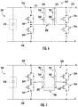
- the dynamic brake assembly 260 includes a plurality of inductors 266 electrically coupled between the switching devices 264.
- the dynamic brake assembly 260 may include at least one resistor 268 electrically coupled to a node 270 positioned between the inductors 266.
- the plurality of switching devices 264 may be arranged in a plurality of pairs 272 of switching devices 264 connected in parallel.
- each of the plurality of inductors 266 may be connected to nodes 274 between first and second switching devices 264 of each of the plurality of pairs of switching devices 272.
- each of the plurality of inductors 266 may be connected to nodes 276 associated with separate switching devices 264 that are connected in parallel.
- the dynamic brake assembly 260 may also include a freewheel diode 275 connected in series with each of the separate switching devices 264.
- each of the plurality of inductors 266 may be connected in parallel with the resistor(s) 268.
- the dynamic brake assembly 260 may include a plurality of resistors 268.
- each of the plurality of resistors 268 may be connected in series with one of the plurality of inductors 266 between the switching devices 264 to form a plurality of dynamic brake circuits 278.
- the dynamic brake assembly 260 may further include at least one snubber capacitor 280 electrically coupled between the plurality of dynamic brake circuits 278.
- the addition of the snubber capacitor 280 between the two dynamic brake circuits is configured to change the operation of the circuit by allowing significant reduction of the turn-off switching loss.
- the turn-on of the switching devices 264 can be simultaneous, whereas turn-off can be staggered, such that one switching device turns off before the other.
- the dynamic brake assembly 260 may also include at least one additional resistor 282 connected in series with the snubber capacitor 280. More specifically, as shown, the dynamic brake assembly 260 includes two additional resistors 282 connected in series on opposing sides of the snubber capacitor 280. In another embodiment, the dynamic brake assembly 260 may include at least one additional resistor 282 connected in parallel with the snubber capacitor 280. More specifically, as shown in FIG. 8 , the dynamic brake assembly 260 includes two additional resistors 282 connected in parallel with the snubber capacitor 280.
- the resistor(s) 268 of the dynamic brake assembly 260 may include a split resistor 284, i.e. one that divides voltage between multiple routes.
- a split resistor 284 i.e. one that divides voltage between multiple routes.
- at least one inductor 266 is connected to each connection end of the split resistor 284 to the dynamic brake phase module.
- such inductors 266 are separate components in the circuit.
- the dynamic brake assembly 260 includes a plurality of switching devices 264 connected in parallel with at least one resistance-inductance component 286 electrically coupled between the plurality of switching devices 264.
- the resistance-inductance component 286 is a single component having both resistance 288 and inductance 290 capabilities, i.e. in separate sections of the component.
- the dynamic brake assembly 260 includes a plurality of switching devices 264 connected in parallel with an inductance component 292 electrically coupled between the switching devices 264.
- the inductance component 292 is a single component having inductance capabilities that also has specified and controlled resistance.
- the inductance and resistance are distributed in the composition of the component.
- FIG. 12 a flow diagram of one embodiment of a method 300 for controlling peak voltage of a DC link of a power converter of an electrical power system connected to a power grid with minimal switching losses is illustrated.
- the method 300 will be described herein with reference to the wind turbine 100 and dynamic brake assembly 260 shown in FIGS. 1-11 .
- the disclosed method 300 may be implemented with wind turbines having any other suitable configurations.
- FIG. 12 depicts steps performed in a particular order for purposes of illustration and discussion, the methods discussed herein are not limited to any particular order or arrangement.
- steps of the methods disclosed herein can be omitted, rearranged, combined, and/or adapted in various ways without deviating from the scope of the present disclosure.
- the method 300 includes electrically coupling the dynamic brake assembly 260 (such as any of the embodiments illustrated in FIGS. 4-11 , to the DC link 244 of the power converter 210.
- the method 300 includes receiving a voltage measurement of the DC link 244 of the power converter 210.
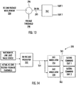
- FIG. 13 a schematic diagram of one embodiment of a control scheme that may be implemented by one of the controllers described herein 202, 262 is illustrated. As shown, the controller 202, 262 receives the voltage measurement 294 via comparator 296.
- the method 300 may also include applying hysteresis to the voltage measurement 294.
- the method 300 further includes comparing the voltage measurement 294 of the DC link 244 to a voltage threshold 298.
- the comparator 296 is configured to compare the voltage measurement 294 and the voltage reference 298 or threshold.
- the controller 202, 262 is configured to determine whether the voltage measurement 294 is equal to or exceeds the voltage threshold 298. If so, as shown at (310), the method 300 includes turning on the dynamic brake assembly 260 of the power converter 210 such that the inductor(s) 266 receives at least part of a load generated by the power converter 210. More specifically, as shown in the illustrated embodiment of FIG.
- the controller 202 may send an "ON" signal 295 to the converter controller 262 such that the converter controller 262 can send appropriate gating commands to the switching devices 264 (i.e. IGBT 1 and IGBT 2). More specifically, in certain embodiments, the controller 202, 262 may alternate on-delays and off-delays of the switching devices 264 to optimize sharing of a load between the switching devices 264.
- the controller 202, 262 may simultaneously turn on the switching devices 264 to optimize sharing of a load between the switching devices 264. As such, there are minimal to no switching losses at turn on. Being a primarily resistive load, the load current is zero when the switching devices 264 turn on, allowing a zero-current turn-on with no switching loss, as long as both switching devices 264 can be previously turned off long enough to allow the load current to drop to zero.
- the controller 202, 262 may stagger turn-off commands for the switching devices 264 such that each switching device turns off at a different time.
- the first switching device 264 that turns off will have zero (or much reduced) switching loss because the load current will shift into the capacitor 280 during the switching event.
- the capacitor 280 becomes a turn-off snubber circuit.
- the second switching device 264 that turns off will have reduced switching loss (nearly zero) because the capacitor 280 will again act as a turn-off snubber.
- a dynamic brake (DB) voltage regulator 352 receives a maximum DC link limit value (e.g. a fixed voltage threshold) and an actual DC link voltage feedback signal (i.e. a variable value). The voltage regulator 352 then generates an output signal 354 that can be received and used by a plurality of dynamic brake modulators 356, 358 for generating respective gating commands 360, 362 for first and second switching devices 264 (e.g. IGBT 1 and IGBT 2).
Landscapes
- Engineering & Computer Science (AREA)
- Power Engineering (AREA)
- Life Sciences & Earth Sciences (AREA)
- Sustainable Development (AREA)
- Sustainable Energy (AREA)
- Chemical & Material Sciences (AREA)
- Combustion & Propulsion (AREA)
- Mechanical Engineering (AREA)
- General Engineering & Computer Science (AREA)
- Control Of Eletrric Generators (AREA)
Abstract
Description
- The present disclosure relates generally to wind turbines and, more particularly, to improved dynamic brake circuit assemblies for wind turbines.
- Wind power is considered one of the cleanest, most environmentally friendly energy sources presently available, and wind turbines have gained increased attention in this regard. A modern wind turbine typically includes a tower, generator, gearbox, nacelle, and one or more rotor blades. The rotor blades capture kinetic energy of wind using known airfoil principles. For example, rotor blades typically have the cross-sectional profile of an airfoil such that, during operation, air flows over the blade producing a pressure difference between the sides. Consequently, a lift force, which is directed from a pressure side towards a suction side, acts on the blade. The lift force generates torque on the main rotor shaft, which is geared to a generator for producing electricity.
- During operation, wind impacts the rotor blades and the blades transform wind energy into a mechanical rotational torque that rotatably drives a low-speed shaft. The low-speed shaft is configured to drive the gearbox that subsequently steps up the low rotational speed of the low-speed shaft to drive a high-speed shaft at an increased rotational speed. The high-speed shaft is generally rotatably coupled to a generator so as to rotatably drive a generator rotor. As such, a rotating magnetic field may be induced by the generator rotor and a voltage may be induced within a generator stator that is magnetically coupled to the generator rotor. The associated electrical power can be transmitted to a main transformer that is typically connected to a power grid via a grid breaker. Thus, the main transformer steps up the voltage amplitude of the electrical power such that the transformed electrical power may be further transmitted to the power grid.
- In many wind turbines, the generator may be electrically coupled to a bi-directional power converter that includes a rotor-side converter joined to a line-side converter via a regulated DC link. Further, wind turbine power systems may include a variety of generator types, including but not limited to a doubly-fed induction generator (DFIG).
- DFIG operation is typically characterized in that the rotor circuit is supplied with current from a current-regulated power converter. As such, the power converter can provide nearly instantaneous regulation of its output currents with respect to the grid frequency. Under steady operating conditions, the rotor-side converter controls the magnitude and phase of currents in the rotor circuit to achieve desired values of electromagnetic torque. Reactive power flow into the line-connected stator terminals of the generator can also be controlled.
- Such DFIG wind turbines may or may not be equipped with a dynamic brake that includes parallel insulated-gate bipolar transistors (IGBTs) which feed power into a resistor. Minimum components for the dynamic brake typically include a switch (typically a semiconductor such as an IGBT) and a resistor and may also include one or more diode(s) in parallel with either the switch, the resistor, or both, as well as other components. Without dynamic braking, typical operation of a DFIG wind turbine is configured to regulate the positive sequence voltage with a closed-loop current regulation scheme which minimizes negative sequence current. As the length of the transmission line feeder to the DFIG wind turbine is increased, however, response to grid transients and grid disturbances causes oscillations of power into and out of the power converter, which can create disturbances on the DC bus voltage therein. As longer transmission line length is typically desired (and possibly coupled with larger grid voltage transients), the voltage overshoots on the DC bus voltage in the power converter may reach a level that damages the converter components. Thus, the dynamic brake may be used to control the peak voltage on the DC bus.
- For conventional dynamic brakes, controls for the switch may be operated based solely on the level of the DC bus voltage in the power converter. As converter power levels continue to increase, additional IGBTs must be placed in parallel to conduct the current. Therefore, it is important to balance the loss in the parallel IGBTs because the loss directly impacts the junction temperature, and the IGBT with the highest junction temperature is the limit in the total energy that can be fed into the resistor.
- Thus, the present disclosure is directed to an improved dynamic brake circuit assembly for a wind turbine that addresses the aforementioned issues.
- Aspects and advantages of the invention will be set forth in part in the following description, or may be obvious from the description, or may be learned through practice of the invention.
- In one aspect, the present subject matter is directed to a power converter assembly for an electrical power system connected to a power grid. The power converter assembly includes a rotor-side converter configured for coupling to a generator rotor of a generator of the electrical power system, a line-side converter electrically coupled to rotor-side converter via a DC link, at least one sensor configured to monitor at voltage parameter of the DC link, and a dynamic brake assembly electrically coupled to the DC link. The line-side converter is configured for coupling to the power grid. The dynamic brake assembly includes a plurality of switching devices connected in parallel and a plurality of inductors electrically coupled between the plurality of switching devices. Thus, when the voltage parameter is at or above a voltage threshold, the dynamic brake assembly is configured to turn on such that the plurality of inductors receives at least part of a load generated by the power converter assembly.
- In one embodiment, the dynamic brake assembly may include at least one resistor electrically coupled to a node positioned between the plurality of inductors. In another embodiment, the resistor(s) may include a split resistor.
- In further embodiments, the plurality of switching devices may be arranged in a plurality of pairs of switching devices connected in parallel. In such embodiments, each of the plurality of inductors may be connected to nodes between first and second switching devices of each of the plurality of pairs of switching devices.
- In additional embodiments, each of the plurality of inductors may be connected in parallel with the resistor(s). In alternative embodiments, the dynamic brake assembly may include a plurality of resistors. In such embodiments, each of the plurality of resistors may be connected in series with one of the plurality of inductors between the plurality of switching devices to form a plurality of dynamic brake circuits.
- In several embodiments, the dynamic brake assembly may further include at least one snubber capacitor electrically coupled between the plurality of dynamic brake circuits. In such embodiments, the dynamic brake assembly may include at least one additional resistor connected in series with the snubber capacitor. In another embodiment, the dynamic brake assembly may include at least one additional resistor connected in parallel with the snubber capacitor.
- In certain embodiments, the plurality of switching devices may be insulated-gate bipolar transistors (IGBTs). In additional embodiments, the electrical power system may be part of a wind turbine power system. In another embodiment, the generator may be a doubly-fed induction generator (DFIG).
- In another aspect, the present disclosure is directed to a power converter assembly for an electrical power system connected to a power grid. The power converter assembly includes a rotor-side converter configured for coupling to a generator rotor of a generator of the electrical power system, a line-side converter electrically coupled to rotor-side converter via a DC link, at least one sensor configured to monitor at voltage parameter of the DC link, and a dynamic brake assembly electrically coupled to the DC link. The line-side converter is configured for coupling to the power grid. The dynamic brake assembly includes a plurality of switching devices connected in parallel and at least one resistance-inductance component electrically coupled between the plurality of switching devices. Thus, when the voltage parameter is at or above a voltage threshold, the dynamic brake assembly is configured to turn on such that the resistance-inductance component receives at least part of a load generated by the power converter assembly. It should be understood that the power converter may further include any of the additional features as described herein.
- In yet another aspect, the present disclosure is directed to a method for controlling peak voltage of a DC link of a power converter of an electrical power system connected to a power grid with minimal switching losses. The method includes electrically coupling a dynamic brake assembly to a DC link of the power converter. The dynamic brake includes a plurality of switching devices connected in parallel and a plurality of inductors electrically coupled between the plurality of switching devices. The method also includes receiving a voltage measurement of the DC link of the power converter. Further, the method includes comparing the voltage measurement of the DC link to a voltage threshold. When the voltage measurement is at or above the voltage threshold, the method includes turning on the dynamic brake assembly of the power converter such that the at least one inductor receives at least part of a load generated by the power converter.
- In one embodiment, the method may include applying hysteresis to the voltage measurement. In another embodiment, the step of turning on the dynamic brake assembly of the power converter may include determining at least one gating command for each of the plurality of switching devices. More specifically, in certain embodiments, the step of determining the gating command(s) for each of the plurality of switching devices may include time-shifting on-delays and off-delays of the plurality of switching devices to optimize sharing of a load between the plurality of switching devices.
- In further embodiments, as mentioned, the dynamic brake assembly may include a plurality of resistors and a plurality of inductors coupled between the plurality of switching devices, with each of the plurality of resistors connected in series with one of the plurality of inductors to form a plurality of dynamic brake circuits. In such embodiments, the dynamic brake assembly may also include at least one snubber capacitor coupled between the plurality of dynamic brake circuits. Thus, in particular embodiments, the step of determining the gating command(s) for each of the plurality of switching devices may include simultaneously turning on the plurality of switching devices to optimize sharing of a load between the plurality of switching devices and time-shifting turn-off commands for the plurality of switching devices such that each switching device turns off at a different time. It should be understood that the method may further include any of the additional steps and/or features as described herein.
- These and other features, aspects and advantages of the present invention will become better understood with reference to the following description and appended claims. The accompanying drawings, which are incorporated in and constitute a part of this specification, illustrate embodiments of the invention and, together with the description, serve to explain the principles of the invention.
- A full and enabling disclosure of the present invention, including the best mode thereof, directed to one of ordinary skill in the art, is set forth in the specification, which makes reference to the appended figures, in which:
-
FIG. 1 illustrates a perspective view of a portion of one embodiment of a wind turbine according to the present disclosure; -
FIG. 2 illustrates a schematic view of one embodiment of an electrical power system suitable for use with the wind turbine shown inFIG. 2 ; -
FIG. 3 illustrates a block diagram of one embodiment of a controller suitable for use with the wind turbine shown inFIG. 2 ; -
FIG. 4 illustrates a schematic diagram of one embodiment of a dynamic brake assembly according to the present disclosure; -
FIG. 5 illustrates a schematic diagram of another embodiment of a dynamic brake assembly according to the present disclosure; -
FIG. 6 illustrates a schematic diagram of yet another embodiment of a dynamic brake assembly according to the present disclosure; -
FIG. 7 illustrates a schematic diagram of still another embodiment of a dynamic brake assembly according to the present disclosure; -
FIG. 8 illustrates a schematic diagram of a further embodiment of a dynamic brake assembly according to the present disclosure; -
FIG. 9 illustrates a schematic diagram of another embodiment of a dynamic brake assembly according to the present disclosure; -
FIG. 10 illustrates a schematic diagram of yet another embodiment of a dynamic brake assembly according to the present disclosure; -
FIG. 11 illustrates a schematic diagram of still another embodiment of a dynamic brake assembly according to the present disclosure; -
FIG. 12 illustrates a flow diagram of one embodiment of a method for controlling peak voltage of a DC link of a power converter of an electrical power system connected to a power grid with minimal switching losses according to the present disclosure; -
FIG. 13 illustrates a simplified, schematic diagram of one embodiment of a control scheme for a dynamic brake assembly according to the present disclosure; and -
FIG. 14 illustrates a detailed, schematic diagram of another embodiment of a control scheme for a dynamic brake assembly according to the present disclosure. - Reference now will be made in detail to embodiments of the invention, one or more examples of which are illustrated in the drawings. Each example is provided by way of explanation of the invention, not limitation of the invention. In fact, it will be apparent to those skilled in the art that various modifications and variations can be made in the present invention without departing from the scope or spirit of the invention. For instance, features illustrated or described as part of one embodiment can be used with another embodiment to yield a still further embodiment. Thus, it is intended that the present invention covers such modifications and variations as come within the scope of the appended claims and their equivalents.
- Referring now to the drawings,
FIG. 1 illustrates a perspective view of a portion of one embodiment of awind turbine 100 according to the present disclosure that is configured to implement the method as described herein. As shown, thewind turbine 100 includes anacelle 102 that typically houses a generator (not shown). Thenacelle 102 is mounted on atower 104 having any suitable height that facilitates operation ofwind turbine 100 as described herein. Thewind turbine 100 also includes arotor 106 that includes threeblades 108 attached to arotating hub 110. Alternatively, thewind turbine 100 may include any number ofblades 108 that facilitates operation of thewind turbine 100 as described herein. - Referring to
FIG. 2 , a schematic view of one embodiment of anelectrical power system 200 that may be used with thewind turbine 100 is illustrated. It should be understood thatFIG. 2 is provided as an example embodiment only and is not meant to be limiting. More specifically, as shown, the electrical power system corresponds to a doubly-fed induction generator (DFIG) power system. In alternative embodiments, however, theelectrical power system 200 may correspond to a full power conversion system. - During operation, wind impacts the
rotor blades 108 and theblades 108 transform wind energy into a mechanical rotational torque that rotatably drives a low-speed shaft 112 via thehub 110. The low-speed shaft 112 is configured to drive agearbox 114 that subsequently steps up the low rotational speed of the low-speed shaft 112 to drive a high-speed shaft 116 at an increased rotational speed. The high-speed shaft 116 is generally rotatably coupled to agenerator 118 so as to rotatably drive agenerator rotor 122. In one embodiment, thegenerator 118 may be a wound rotor, three-phase, DFIG that includes agenerator stator 120 magnetically coupled to agenerator rotor 122. As such, a rotating magnetic field may be induced by thegenerator rotor 122 and a voltage may be induced within agenerator stator 120 that is magnetically coupled to thegenerator rotor 122. In one embodiment, thegenerator 118 is configured to convert the rotational mechanical energy to a sinusoidal, three-phase alternating current (AC) electrical energy signal in thegenerator stator 120. The associated electrical power can be transmitted to amain transformer 234 via astator bus 208, astator synchronizing switch 206, asystem bus 216, a maintransformer circuit breaker 214, and a generator-side bus 236. Themain transformer 234 steps up the voltage amplitude of the electrical power such that the transformed electrical power may be further transmitted to a grid via agrid circuit breaker 238, a breaker-side bus 240, and agrid bus 242. - In addition, the
electrical power system 200 may include awind turbine controller 202 configured to control any of the components of thewind turbine 100 and/or implement the method steps as described herein. For example, as shown particularly inFIG. 3 , thecontroller 202 may include one or more processor(s) 204 and associated memory device(s) 207 configured to perform a variety of computer-implemented functions (e.g., performing the methods, steps, calculations and the like and storing relevant data as disclosed herein). Additionally, thecontroller 202 may also include acommunications module 209 to facilitate communications between thecontroller 202 and the various components of thewind turbine 100, e.g. any of the components ofFIG. 2 . Further, thecommunications module 209 may include a sensor interface 211 (e.g., one or more analog-to-digital converters) to permit signals transmitted from one or more sensors to be converted into signals that can be understood and processed by theprocessors 204. It should be appreciated that the sensors (e.g. sensors communications module 209 using any suitable means. For example, as shown inFIG. 3 , thesensors sensor interface 211 via a wired connection. However, in other embodiments, thesensors sensor interface 211 via a wireless connection, such as by using any suitable wireless communications protocol known in the art. As such, theprocessor 204 may be configured to receive one or more signals from thesensors - As used herein, the term "processor" refers not only to integrated circuits referred to in the art as being included in a computer, but also refers to a controller, a microcontroller, a microcomputer, a programmable logic controller (PLC), an application specific integrated circuit, and other programmable circuits. The
processor 204 is also configured to compute advanced control algorithms and communicate to a variety of Ethernet or serial-based protocols (Modbus, OPC, CAN, etc.). Additionally, the memory device(s) 207 may generally comprise memory element(s) including, but not limited to, computer readable medium (e.g., random access memory (RAM)), computer readable non-volatile medium (e.g., a flash memory), a floppy disk, a compact disc-read only memory (CD-ROM), a magnetooptical disk (MOD), a digital versatile disc (DVD) and/or other suitable memory elements. Such memory device(s) 207 may generally be configured to store suitable computer-readable instructions that, when implemented by the processor(s) 204, configure thecontroller 202 to perform the various functions as described herein. - Referring back to
FIG. 2 , thegenerator stator 120 may be electrically coupled to astator synchronizing switch 206 via thestator bus 208. In one embodiment, thegenerator rotor 122 may be electrically coupled to a bi-directionalpower converter assembly 210 or power converter via arotor bus 212. Alternatively, thegenerator rotor 122 may be electrically coupled to therotor bus 212 via any other device that facilitates operation ofelectrical power system 200 as described herein. In a further embodiment, thestator synchronizing switch 206 may be electrically coupled to the maintransformer circuit breaker 214 via thesystem bus 216. - In addition, as shown, the power converter assembly 210 (also referred to herein as a power converter) may include a rotor-
side power converter 220 electrically coupled to a line-side power converter 222 via a single direct current (DC) link 244. Alternatively, the rotor-side power converter 220 and the line-side power converter 222 may be electrically coupled via individual and separate DC links. In addition, as shown, the DC link 244 may include apositive rail 246, anegative rail 248, and at least onecapacitor 250 coupled therebetween. - In addition, the line-
side power converter 222 may be electrically coupled to aline bus 224 that includes aline contactor 226. In addition, theline contactor 226 may be electrically coupled to aconversion circuit breaker 228 via a conversioncircuit breaker bus 230. In addition, theconversion circuit breaker 228 may be electrically coupled to the maintransformer circuit breaker 214 viasystem bus 216 and aconnection bus 232. The maintransformer circuit breaker 214 may be electrically coupled to an electric powermain transformer 234 via a generator-side bus 236. Themain transformer 234 may be electrically coupled to agrid circuit breaker 238 via the breaker-side bus 240. In addition, as shown, thegrid circuit breaker 238 may be connected to the electric power transmission and distribution grid via thegrid bus 242. - In operation, alternating current (AC) power generated at the
generator stator 120 by rotation of therotor 106 is provided via a dual path to thegrid bus 242. The dual paths are defined by thestator bus 208 and therotor bus 212. On therotor bus side 212, sinusoidal multi-phase (e.g. three-phase) AC power is provided to thepower converter assembly 210. The rotor-side power converter 220 converts the AC power provided from therotor bus 212 into DC power and provides the DC power to theDC link 244. Switching elements (e.g. IGBTs) used in bridge circuits of the rotor-side power converter 220 can be modulated to convert the AC power provided from therotor bus 212 into DC power suitable for theDC link 244. In addition, as shown, thepower converter assembly 210 may also include adynamic brake assembly 260 electrically coupled between the rotor-side converter 220 and the line-side converter 222, which will be discussed in more detail below in reference toFIGS. 4-11 . - Still referring to
FIG. 2 , the line-side converter 222 converts the DC power on the DC link 244 into AC output power suitable for theelectrical grid bus 242. In particular, switching elements (e.g. IGBTs) used in bridge circuits of the line-side power converter 222 can be modulated to convert the DC power on the DC link 244 into AC power on the line-side bus 225. The AC power from thepower converter assembly 210 can be combined with the power from thegenerator stator 120 to provide multi-phase power (e.g. three-phase power) having a frequency maintained substantially at the frequency of the electrical grid bus 242 (e.g. 50 Hz/60 Hz). It should be understood that the rotor-side power converter 220 and the line-side power converter 222 may have any configuration using any switching devices that facilitate operation ofelectrical power system 200 as described herein. - Further, the
power converter assembly 210 may be coupled in electronic data communication with theturbine controller 202 and/or a separate orintegral converter controller 262 to control the operation of the rotor-side power converter 220 and the line-side power converter 222. For example, during operation, one or more of thecontrollers sensors controllers wind turbine 100 via thesensors sensors power grid bus 242. Alternatively, thesensors electrical power system 200, such as the DC link 244, that facilitates operation ofelectrical power system 200 as described herein. - It should also be understood that any number or type of sensors may be employed within the
wind turbine 100 and at any location. For example, thesensors converter controller 262 is configured to receive one or more feedback signals from thesensors converter controller 262 may be configured with any of the features described herein in regards to themain controller 202. Further, theconverter controller 262 may be separate from or integral with themain controller 202. As such, theconverter controller 262 is configured to implement the various method steps as described herein and may be configured similar to theturbine controller 202. - Referring now to
FIGS. 4-11 , schematic diagrams of various embodiments of thedynamic brake assembly 260 according to the present disclosure are illustrated. More specifically, as shown, thedynamic brake assembly 260 is electrically coupled to the DC link 244 between the positive andnegative rails dynamic brake assembly 260 connected to thepositive rail 246, it should be understood that thedynamic brake assembly 260 may also be coupled to thenegative rail 248. Further, as shown, thedynamic brake assembly 260 includes a plurality of switchingdevices 264 connected in parallel. For example, as shown in the illustrated embodiments, the switchingdevices 264 are insulated-gate bipolar transistors (IGBTs). In additional embodiments, the switchingdevices 264 may also include one or more diodes. In addition, as shown, thedynamic brake assembly 260 includes a plurality ofinductors 266 electrically coupled between the switchingdevices 264. In addition, as shown inFIGS. 4 and 5 , thedynamic brake assembly 260 may include at least oneresistor 268 electrically coupled to anode 270 positioned between theinductors 266. - As shown particularly in
FIG. 4 , the plurality of switchingdevices 264 may be arranged in a plurality ofpairs 272 of switchingdevices 264 connected in parallel. In such embodiments, as shown, each of the plurality ofinductors 266 may be connected tonodes 274 between first andsecond switching devices 264 of each of the plurality of pairs of switchingdevices 272. Alternatively, as shown inFIG. 5 , each of the plurality ofinductors 266 may be connected tonodes 276 associated withseparate switching devices 264 that are connected in parallel. In addition, as shown inFIG. 5 , thedynamic brake assembly 260 may also include afreewheel diode 275 connected in series with each of theseparate switching devices 264. Further, each of the plurality ofinductors 266 may be connected in parallel with the resistor(s) 268. - Referring now to
FIGS. 6-8 , thedynamic brake assembly 260 may include a plurality ofresistors 268. In such embodiments, as shown particularly inFIG. 6 , each of the plurality ofresistors 268 may be connected in series with one of the plurality ofinductors 266 between the switchingdevices 264 to form a plurality ofdynamic brake circuits 278. Thus, as shown inFIGS. 6-8 , thedynamic brake assembly 260 may further include at least onesnubber capacitor 280 electrically coupled between the plurality ofdynamic brake circuits 278. In such embodiments, the addition of thesnubber capacitor 280 between the two dynamic brake circuits is configured to change the operation of the circuit by allowing significant reduction of the turn-off switching loss. For example, in the illustrated circuit, the turn-on of theswitching devices 264 can be simultaneous, whereas turn-off can be staggered, such that one switching device turns off before the other. - In addition, as shown in
FIG. 7 , thedynamic brake assembly 260 may also include at least oneadditional resistor 282 connected in series with thesnubber capacitor 280. More specifically, as shown, thedynamic brake assembly 260 includes twoadditional resistors 282 connected in series on opposing sides of thesnubber capacitor 280. In another embodiment, thedynamic brake assembly 260 may include at least oneadditional resistor 282 connected in parallel with thesnubber capacitor 280. More specifically, as shown inFIG. 8 , thedynamic brake assembly 260 includes twoadditional resistors 282 connected in parallel with thesnubber capacitor 280. - Referring now to
FIGS. 9 and10 , the resistor(s) 268 of thedynamic brake assembly 260 may include a split resistor 284, i.e. one that divides voltage between multiple routes. For example, as shown particularly inFIG. 9 , at least oneinductor 266 is connected to each connection end of the split resistor 284 to the dynamic brake phase module. In addition, as shown inFIG. 9 ,such inductors 266 are separate components in the circuit. In an alternative embodiment, as shown inFIG. 10 , thedynamic brake assembly 260 includes a plurality of switchingdevices 264 connected in parallel with at least one resistance-inductance component 286 electrically coupled between the plurality of switchingdevices 264. In such embodiments, the resistance-inductance component 286 is a single component having bothresistance 288 andinductance 290 capabilities, i.e. in separate sections of the component. - Referring now to
FIG. 11 , a schematic diagram of yet another embodiment of thedynamic brake assembly 260 according to the present disclosure is illustrated. As shown, thedynamic brake assembly 260 includes a plurality of switchingdevices 264 connected in parallel with aninductance component 292 electrically coupled between the switchingdevices 264. In such embodiments, theinductance component 292 is a single component having inductance capabilities that also has specified and controlled resistance. In such embodiments, the inductance and resistance are distributed in the composition of the component. - Referring now to
FIG. 12 , a flow diagram of one embodiment of amethod 300 for controlling peak voltage of a DC link of a power converter of an electrical power system connected to a power grid with minimal switching losses is illustrated. In general, themethod 300 will be described herein with reference to thewind turbine 100 anddynamic brake assembly 260 shown inFIGS. 1-11 . However, it should be appreciated that the disclosedmethod 300 may be implemented with wind turbines having any other suitable configurations. In addition, althoughFIG. 12 depicts steps performed in a particular order for purposes of illustration and discussion, the methods discussed herein are not limited to any particular order or arrangement. One skilled in the art, using the disclosures provided herein, will appreciate that various steps of the methods disclosed herein can be omitted, rearranged, combined, and/or adapted in various ways without deviating from the scope of the present disclosure. - As shown at (302), the
method 300 includes electrically coupling the dynamic brake assembly 260 (such as any of the embodiments illustrated inFIGS. 4-11 , to the DC link 244 of thepower converter 210. As shown at (304), themethod 300 includes receiving a voltage measurement of the DC link 244 of thepower converter 210. For example, as shown inFIG. 13 , a schematic diagram of one embodiment of a control scheme that may be implemented by one of the controllers described herein 202, 262 is illustrated. As shown, thecontroller voltage measurement 294 viacomparator 296. Referring back toFIG. 12 , as shown at (312), themethod 300 may also include applying hysteresis to thevoltage measurement 294. - In addition, as shown at (306), the
method 300 further includes comparing thevoltage measurement 294 of the DC link 244 to avoltage threshold 298. For example, as shown inFIG. 13 , thecomparator 296 is configured to compare thevoltage measurement 294 and thevoltage reference 298 or threshold. Referring back toFIG. 12 , as shown at (308), thecontroller voltage measurement 294 is equal to or exceeds thevoltage threshold 298. If so, as shown at (310), themethod 300 includes turning on thedynamic brake assembly 260 of thepower converter 210 such that the inductor(s) 266 receives at least part of a load generated by thepower converter 210. More specifically, as shown in the illustrated embodiment ofFIG. 13 , thecontroller 202 may send an "ON"signal 295 to theconverter controller 262 such that theconverter controller 262 can send appropriate gating commands to the switching devices 264 (i.e.IGBT 1 and IGBT 2). More specifically, in certain embodiments, thecontroller switching devices 264 to optimize sharing of a load between the switchingdevices 264. - In further embodiments, such as those that include the
snubber capacitor 280, thecontroller switching devices 264 to optimize sharing of a load between the switchingdevices 264. As such, there are minimal to no switching losses at turn on. Being a primarily resistive load, the load current is zero when the switchingdevices 264 turn on, allowing a zero-current turn-on with no switching loss, as long as both switchingdevices 264 can be previously turned off long enough to allow the load current to drop to zero. - In addition, the
controller switching devices 264 such that each switching device turns off at a different time. As such, thefirst switching device 264 that turns off will have zero (or much reduced) switching loss because the load current will shift into thecapacitor 280 during the switching event. Hence, thecapacitor 280 becomes a turn-off snubber circuit. Thesecond switching device 264 that turns off will have reduced switching loss (nearly zero) because thecapacitor 280 will again act as a turn-off snubber. It may be advantageous, but not necessary, to operate the turn-off of theswitching devices 264 in a way to alternate the sequence for every other turn-off event, (oneswitching device 264 turns off first, then the other), to better balance their switching, conduction and diode losses. - Referring now to
FIG. 14 , a schematic diagram of one embodiment of adetailed control scheme 350 for thedynamic brake assembly 260 described herein according to the present disclosure is illustrated. As shown, a dynamic brake (DB) voltage regulator 352 (such as a proportional-integral regulator) receives a maximum DC link limit value (e.g. a fixed voltage threshold) and an actual DC link voltage feedback signal (i.e. a variable value). Thevoltage regulator 352 then generates anoutput signal 354 that can be received and used by a plurality ofdynamic brake modulators e.g. IGBT 1 and IGBT 2). - This written description uses examples to disclose the invention, including the best mode, and also to enable any person skilled in the art to practice the invention, including making and using any devices or systems and performing any incorporated methods. The patentable scope of the invention is defined by the claims, and may include other examples that occur to those skilled in the art. Such other examples are intended to be within the scope of the claims if they include structural elements that do not differ from the literal language of the claims, or if they include equivalent structural elements with insubstantial differences from the literal languages of the claims.
- Further disclosed are embodiments according to the following clauses:
- 1. A power converter assembly for an electrical power system connected to a power grid, the power converter assembly comprising:
- a rotor-side converter configured for coupling to a generator rotor of a generator of the electrical power system;
- a line-side converter electrically coupled to rotor-side converter via a DC link, the line-side converter configured for coupling to the power grid;
- at least one sensor configured to monitor at voltage parameter of the DC link; and,
- a dynamic brake assembly electrically coupled to the DC link, the dynamic brake assembly comprising a plurality of switching devices connected in parallel and a plurality of inductors electrically coupled between the plurality of switching devices,
- wherein, when the voltage parameter is at or above a voltage threshold, the dynamic brake assembly is configured to turn on such that the plurality of inductors receives at least part of a load generated by the power converter assembly.
- 2. The power converter assembly of
clause 1, wherein the dynamic brake assembly further comprises a resistor electrically coupled to a node positioned between the plurality of inductors. - 3. The power converter assembly of
clause 2, wherein the resistor comprises a split resistor. - 4. The power converter assembly of
clause 2, wherein the plurality of switching devices may be arranged in a plurality of pairs of switching devices connected in parallel. - 5. The power converter assembly of clause 4, wherein each of the plurality of inductors are connected to nodes between first and second switching devices of each of the plurality of pairs of switching devices.
- 6. The power converter assembly of
clause 2, wherein each of the plurality of inductors is connected in parallel with the resistor. - 7. The power converter assembly of
clause 1, wherein the dynamic brake assembly further comprises a plurality of resistors, each of the plurality of resistors being connected in series with one of the plurality of inductors between the plurality of switching devices to form a plurality of dynamic brake circuits. - 8. The power converter assembly of clause 7, wherein the dynamic brake assembly further comprises at least one snubber capacitor electrically coupled between the plurality of dynamic brake circuits.
- 9. The power converter assembly of clause 8, wherein the dynamic brake assembly further comprises at least one additional resistor connected in series with the snubber capacitor.
- 10. The power converter assembly of clause 9, wherein the dynamic brake assembly further comprises at least one additional resistor connected in parallel with the snubber capacitor.
- 11. The power converter assembly of
clause 1, wherein the plurality of switching devices comprise insulated-gate bipolar transistors (IGBTs). - 12. The power converter assembly of
clause 1, wherein the electrical power system is part of a wind turbine power system, and the generator comprises a doubly-fed induction generator (DFIG). - 13. A power converter assembly for an electrical power system connected to a power grid, the power converter assembly comprising:
- a rotor-side converter configured for coupling to a generator rotor of a generator of the electrical power system;
- a line-side converter electrically coupled to rotor-side converter via a DC link, the line-side converter configured for coupling to the power grid;
- at least one sensor configured to monitor at voltage parameter of the DC link; and,
- a dynamic brake assembly electrically coupled to the DC link, the dynamic brake assembly comprising a plurality of switching devices connected in parallel and at least one resistance-inductance component electrically coupled between the plurality of switching devices,
- wherein, when the voltage parameter is at or above a voltage threshold, the dynamic brake assembly is configured to turn on such that the at least one resistance-inductance component receives at least part of a load generated by the power converter assembly.
- 14. A method for controlling peak voltage of a DC link of a power converter of an electrical power system connected to a power grid with minimal switching losses, the method comprising:
- electrically coupling a dynamic brake assembly to a DC link of the power converter, the dynamic brake having a plurality of switching devices connected in parallel and a plurality of inductors electrically coupled between the plurality of switching devices;
- receiving a voltage measurement of the DC link of the power converter;
- comparing the voltage measurement of the DC link to a voltage threshold;
- when the voltage measurement is at or above the voltage threshold, turning on the dynamic brake assembly of the power converter such that the at least one inductor receives at least part of a load generated by the power converter.
- 15. The method of clause 14, further comprising applying hysteresis to the voltage measurement.
- 16. The method of clause 14, wherein turning on the dynamic brake assembly of the power converter further comprises determining at least one gating command for each of the plurality of switching devices.
- 17. The method of clause 16, wherein determining the at least one gating command for each of the plurality of switching devices further comprises time-shifting on-delays and off-delays of the plurality of switching devices to optimize sharing of a load between the plurality of switching devices.
- 18. The method of clause 14, wherein the dynamic brake assembly further comprises a plurality of resistors and a plurality of inductors coupled between the plurality of switching devices, each of the plurality of resistors connected in series with one of the plurality of inductors to form a plurality of dynamic brake circuits, the dynamic brake assembly further comprising at least one snubber capacitor coupled between the plurality of dynamic brake circuits.
- 19. The method of clause 18, wherein determining the at least one gating command for each of the plurality of switching devices further comprises:
- simultaneously turning on the plurality of switching devices to optimize sharing of a load between the plurality of switching devices; and,
- time-shifting turn-off commands for the plurality of switching devices such that each switching device turns off at a different time.
- 20. The method of clause 14, wherein the dynamic brake assembly further comprises a resistor electrically coupled to a node positioned between the plurality of inductors.
Claims (15)
- A power converter assembly (210) for an electrical power system (200) connected to a power grid (242), the power converter assembly (210) comprising:a rotor-side converter (220) configured for coupling to a generator rotor (122) of a generator (118) of the electrical power system (200);a line-side converter (222) electrically coupled to rotor-side converter (220) via a DC link (244), the line-side converter (222) configured for coupling to the power grid (242);at least one sensor configured to monitor at voltage parameter of the DC link (244); and,a dynamic brake assembly (260) electrically coupled to the DC link (244), the dynamic brake assembly (260) comprising a plurality of switching devices (264) connected in parallel and a plurality of inductors (266) electrically coupled between the plurality of switching devices (264),wherein, when the voltage parameter is at or above a voltage threshold, the dynamic brake assembly (260) is configured to turn on such that the plurality of inductors (266) receives at least part of a load generated by the power converter assembly (210).
- The power converter assembly (210) of claim 1, wherein the dynamic brake assembly (260) further comprises a resistor (268) electrically coupled to a node (270) positioned between the plurality of inductors (266).
- The power converter assembly (210) of claim 2, wherein the resistor (268) comprises a split resistor.
- The power converter assembly (210) of claim 1 or 2, wherein the plurality of switching devices (264) may be arranged in a plurality of pairs (272) of switching devices (264) connected in parallel.
- The power converter assembly (210) of claim 4, wherein each of the plurality of inductors (266) are connected to nodes (274) between first and second switching devices (264) of each of the plurality of pairs of switching devices (264).
- The power converter assembly (210) of any of the preceding claims, wherein each of the plurality of inductors (266) is connected in parallel with the resistor (268).
- The power converter assembly (210) of any of the preceding claims, wherein the dynamic brake assembly (260) further comprises a plurality of resistors (268), each of the plurality of resistor (268)s being connected in series with one of the plurality of inductors (266) between the plurality of switching devices (264) to form a plurality of dynamic brake circuits.
- The power converter assembly (210) of claim 7, wherein the dynamic brake assembly (260) further comprises at least one snubber capacitor electrically coupled between the plurality of dynamic brake circuits.
- The power converter assembly (210) of claim 8, wherein the dynamic brake assembly (260) further comprises at least one additional resistor (268) connected in series with the snubber capacitor.
- The power converter assembly (210) of claim 9, wherein the dynamic brake assembly (260) further comprises at least one additional resistor (268) connected in parallel with the snubber capacitor.
- The power converter assembly (210) of any of the preceding claims, wherein the plurality of switching devices (264) comprise insulated-gate bipolar transistors (IGBTs).
- The power converter assembly (210) of any of the preceding claims, wherein the electrical power system (200) is part of a wind turbine power system, and the generator (118) comprises a doubly-fed induction generator (118) (DFIG).
- A method (300) for controlling peak voltage of a DC link (244) of a power converter (210) of an electrical power system (200) connected to a power grid (242) with minimal switching losses, the method (300) comprising:electrically coupling a dynamic brake assembly (260) to a DC link (244) of the power converter (210), the dynamic brake assembly (260) having a plurality of switching devices (264) connected in parallel and a plurality of inductors (266) electrically coupled between the plurality of switching devices (264);receiving a voltage measurement of the DC link (244) of the power converter (210);comparing the voltage measurement of the DC link (244) to a voltage threshold;when the voltage measurement is at or above the voltage threshold, turning on the dynamic brake assembly (260) of the power converter (210) such that the at least one inductor (266) receives at least part of a load generated by the power converter (210).
- The method (300) of claim 13, further comprising applying hysteresis to the voltage measurement.
- The method (300) of claim 14, wherein turning on the dynamic brake assembly (260) of the power converter (210) further comprises determining at least one gating command for each of the plurality of switching devices (264).
Applications Claiming Priority (1)
| Application Number | Priority Date | Filing Date | Title |
|---|---|---|---|
| US16/113,213 US10615727B2 (en) | 2018-08-27 | 2018-08-27 | Dynamic brake circuit assembly for a wind turbine |
Publications (2)
| Publication Number | Publication Date |
|---|---|
| EP3618264A1 true EP3618264A1 (en) | 2020-03-04 |
| EP3618264B1 EP3618264B1 (en) | 2024-09-25 |
Family
ID=67777087
Family Applications (1)
| Application Number | Title | Priority Date | Filing Date |
|---|---|---|---|
| EP19193887.7A Active EP3618264B1 (en) | 2018-08-27 | 2019-08-27 | Dynamic brake circuit assembly for a wind turbine |
Country Status (4)
| Country | Link |
|---|---|
| US (1) | US10615727B2 (en) |
| EP (1) | EP3618264B1 (en) |
| DK (1) | DK3618264T3 (en) |
| ES (1) | ES2999615T3 (en) |
Families Citing this family (5)
| Publication number | Priority date | Publication date | Assignee | Title |
|---|---|---|---|---|
| US10742149B1 (en) * | 2019-04-22 | 2020-08-11 | General Electric Company | System and method for reactive power control of a wind turbine by varying switching frequency of rotor side converter |
| EP4222852A1 (en) * | 2020-10-01 | 2023-08-09 | Vestas Wind Systems A/S | Method for reduction of dc link busbar and capacitor current, by adjustment of a pwm carrier delay |
| EP4089869B1 (en) * | 2021-05-10 | 2024-04-17 | General Electric Technology GmbH | Electrical assembly |
| WO2022244166A1 (en) * | 2021-05-19 | 2022-11-24 | ファナック株式会社 | Temperature inference device and converter system |
| US12015276B2 (en) * | 2022-02-16 | 2024-06-18 | Ge Infrastructure Technology Llc | System and method for pre-charging a DC link of a power converter |
Citations (4)
| Publication number | Priority date | Publication date | Assignee | Title |
|---|---|---|---|---|
| US20050116476A1 (en) * | 2002-01-29 | 2005-06-02 | Lorenz Feddersen | Circuit to be used in a wind power plant |
| EP2741414A2 (en) * | 2012-12-07 | 2014-06-11 | General Electric Company | System and Method for Optimization of Dual Bridge Doubly Fed Induction Generator (DFIG) |
| EP2887518A1 (en) * | 2013-12-23 | 2015-06-24 | General Electric Company | Optimized filter for battery energy storage on alternate energy systems |
| CN106505620A (en) * | 2016-11-25 | 2017-03-15 | 国家电网公司 | A kind of transient state reconfiguration system for improving double-fed fan trouble ride-through capability and control method |
Family Cites Families (52)
| Publication number | Priority date | Publication date | Assignee | Title |
|---|---|---|---|---|
| US5907192A (en) * | 1997-06-09 | 1999-05-25 | General Electric Company | Method and system for wind turbine braking |
| US6396137B1 (en) * | 2000-03-15 | 2002-05-28 | Kevin Mark Klughart | Integrated voltage/current/power regulator/switch system and method |
| CN101091305A (en) * | 2004-12-28 | 2007-12-19 | 维斯塔斯风力系统有限公司 | Method of controlling a wind turbine connected to an electric utility grid |
| EP1768223B1 (en) * | 2005-09-27 | 2021-10-20 | Siemens Gamesa Renewable Energy Innovation & Technology, S.L. | Method for operation of a converter system |
| US7423412B2 (en) * | 2006-01-31 | 2008-09-09 | General Electric Company | Method, apparatus and computer program product for injecting current |
| US7586216B2 (en) * | 2006-06-02 | 2009-09-08 | General Electric Company | Redundant electrical brake and protection system for electric generators |
| US7629705B2 (en) * | 2006-10-20 | 2009-12-08 | General Electric Company | Method and apparatus for operating electrical machines |
| JP5118913B2 (en) * | 2007-07-24 | 2013-01-16 | トヨタ自動車株式会社 | Power supply system, electric vehicle equipped with the same, and control method of power supply system |
| US8080973B2 (en) * | 2008-10-22 | 2011-12-20 | General Electric Company | Apparatus for energy transfer using converter and method of manufacturing same |
| US7999418B2 (en) * | 2008-12-22 | 2011-08-16 | General Electric Company | Electrical system and control method |
| US8018082B2 (en) * | 2009-11-25 | 2011-09-13 | General Electric Company | Method and apparatus for controlling a wind turbine |
| US8698451B2 (en) * | 2009-12-18 | 2014-04-15 | General Electric Company | Apparatus and method for rapid charging using shared power electronics |
| US8093741B2 (en) * | 2010-10-29 | 2012-01-10 | General Electric Company | Method and system for providing increased turbine output for doubly fed induction generator |
| DK2463996T3 (en) * | 2010-12-08 | 2013-08-05 | Siemens Ag | AC to AC converter and method of converting an AC frequency with a first frequency to an AC voltage with a second frequency |
| US9450412B2 (en) * | 2010-12-22 | 2016-09-20 | General Electric Company | Method and system for control power in remote DC power systems |
| US8432055B2 (en) * | 2011-12-12 | 2013-04-30 | General Electric Company | Wind turbine having a high-voltage ride through (HVRT) mode |
| US9041234B2 (en) * | 2012-03-26 | 2015-05-26 | Rockwell Automation Technologies, Inc. | Double fed induction generator (DFIG) converter and method for improved grid fault ridethrough |
| JP5904092B2 (en) * | 2012-03-26 | 2016-04-13 | 株式会社デンソー | Power conversion control device |
| AU2012385428B2 (en) * | 2012-07-12 | 2017-04-06 | General Electric Renovables España, S.L. | Dynamic braking system for an electric power system and method of operating the same |
| CN104471242B (en) * | 2012-07-19 | 2017-12-19 | 维斯塔斯风力系统集团公司 | Operate the method and its applicable system of wind turbine |
| EP2891217A4 (en) * | 2012-08-30 | 2016-05-25 | Gen Electric | SYSTEM AND METHOD FOR PROTECTING ELECTRIC MACHINES |
| US9450415B2 (en) * | 2012-08-31 | 2016-09-20 | General Electric Company | System and method for controlling a dual-fed induction generator in response to high-voltage grid events |
| US8664788B1 (en) * | 2012-09-07 | 2014-03-04 | General Electric Company | Method and systems for operating a wind turbine using dynamic braking in response to a grid event |
| US9030174B2 (en) * | 2012-09-14 | 2015-05-12 | General Electric Company | Current balance control in converter for doubly fed induction generator wind turbine system |
| US20140203559A1 (en) * | 2013-01-18 | 2014-07-24 | General Electric Company | Connection for improved current balancing between parallel bridge circuits |
| CN104052373B (en) * | 2013-03-14 | 2017-04-12 | 通用电气公司 | motor fault protection system and method |
| DK3004637T4 (en) * | 2013-06-04 | 2021-02-15 | Gen Electric | METHODS FOR OPERATING WIND TURBINE SYSTEM WITH DYNAMIC BRAKE |
| US8975768B2 (en) * | 2013-06-05 | 2015-03-10 | General Electic Company | Methods for operating wind turbine system having dynamic brake |
| CN104348342B (en) * | 2013-08-02 | 2019-05-31 | 通用电气公司 | Electric energy conversion system and method |
| US20150131349A1 (en) * | 2013-11-12 | 2015-05-14 | General Electric Company | System and method for balancing multilevel power converters |
| ES2950289T3 (en) * | 2013-12-18 | 2023-10-06 | Ingeteam Power Tech Sa | Variable impedance device for a wind turbine |
| US20150214830A1 (en) * | 2014-01-24 | 2015-07-30 | General Electric Company | System and method of power conversion |
| WO2015142324A1 (en) * | 2014-03-19 | 2015-09-24 | General Electric Company | Hybrid three-level npc thyristor converter with chain-link strings as inner ac switches |
| US9667057B2 (en) * | 2014-06-18 | 2017-05-30 | General Electric Company | System and method for protecting a power converter during an adverse voltage event |
| US10104814B2 (en) * | 2014-11-03 | 2018-10-16 | General Electric Company | System and method for cooling electrical components of a power converter |
| US20160165684A1 (en) * | 2014-12-05 | 2016-06-09 | General Electric Company | Power conversion system |
| CN105826917B (en) * | 2015-01-04 | 2019-10-08 | 通用电气公司 | Power conversion system and its control method and wind turbine electricity generating system |
| GB2536269A (en) * | 2015-03-12 | 2016-09-14 | Hamilton Sundstrand Corp | Inrush limiter for motor drive AC/AC power converters |
| US9831717B2 (en) * | 2015-09-16 | 2017-11-28 | General Electric Company | Systems and methods for operating uninterruptible power supplies |
| US10243370B2 (en) * | 2015-12-07 | 2019-03-26 | General Electric Company | System and method for integrating energy storage into modular power converter |
| WO2017108046A1 (en) | 2015-12-22 | 2017-06-29 | Vestas Wind Systems A/S | Power dissipation system and control method for a wind turbine power converter |
| US10520050B2 (en) * | 2016-01-23 | 2019-12-31 | Kollmorgen Corporation | Method and apparatus for power-saving, fail-safe control of an electromechanical brake |
| EP3200331B1 (en) * | 2016-01-27 | 2019-11-20 | GE Energy Power Conversion Technology Ltd | Method to protect a power converter arrangement and power converter arrangement with a protective device |
| US10075114B2 (en) * | 2016-03-03 | 2018-09-11 | General Electric Company | System and method for controlling DC link voltage of a power converter |
| US10071634B2 (en) * | 2016-03-22 | 2018-09-11 | Ford Global Technologies, Llc | Dynamic IGBT gate drive to reduce switching loss |
| US10090792B2 (en) * | 2016-12-08 | 2018-10-02 | Ford Global Technologies, Llc | Self-balancing parallel power devices with a temperature compensated gate driver |
| US10843793B2 (en) * | 2017-05-31 | 2020-11-24 | Simmonds Precision Products, Inc. | Electronic braking arrangements |
| US10457150B2 (en) * | 2017-06-08 | 2019-10-29 | Ford Global Technologies, Llc | Voltage stack-up converter for electrified vehicle |
| US20180366970A1 (en) * | 2017-06-20 | 2018-12-20 | Ford Global Technologies, Llc | Junction temperature compensated gate driver |
| US10320220B2 (en) * | 2017-08-23 | 2019-06-11 | Ford Global Technologies, Llc | Configurable hybrid drive systems |
| US10680538B2 (en) * | 2017-09-28 | 2020-06-09 | Otis Elevator Company | Emergency braking for a drive system |
| US10432186B2 (en) * | 2017-11-14 | 2019-10-01 | Ford Global Technologies, Llc | Variable resistance power switch feedback |
-
2018
- 2018-08-27 US US16/113,213 patent/US10615727B2/en active Active
-
2019
- 2019-08-27 DK DK19193887.7T patent/DK3618264T3/en active
- 2019-08-27 ES ES19193887T patent/ES2999615T3/en active Active
- 2019-08-27 EP EP19193887.7A patent/EP3618264B1/en active Active
Patent Citations (4)
| Publication number | Priority date | Publication date | Assignee | Title |
|---|---|---|---|---|
| US20050116476A1 (en) * | 2002-01-29 | 2005-06-02 | Lorenz Feddersen | Circuit to be used in a wind power plant |
| EP2741414A2 (en) * | 2012-12-07 | 2014-06-11 | General Electric Company | System and Method for Optimization of Dual Bridge Doubly Fed Induction Generator (DFIG) |
| EP2887518A1 (en) * | 2013-12-23 | 2015-06-24 | General Electric Company | Optimized filter for battery energy storage on alternate energy systems |
| CN106505620A (en) * | 2016-11-25 | 2017-03-15 | 国家电网公司 | A kind of transient state reconfiguration system for improving double-fed fan trouble ride-through capability and control method |
Non-Patent Citations (2)
| Title |
|---|
| VINOTHKUMAR K ET AL: "Enhanced fault ride-through scheme and coordinated reactive power control for DFIG", SUSTAINABLE ENERGY TECHNOLOGIES (ICSET), 2010 IEEE INTERNATIONAL CONFERENCE ON, IEEE, PISCATAWAY, NJ, USA, 6 December 2010 (2010-12-06), pages 1 - 5, XP031846903, ISBN: 978-1-4244-7192-8 * |
| XIANGWU YAN ET AL: "Grid-Fault Tolerant Operation of a DFIG Wind Turbine Generator Using a Passive Resistance Network", IEEE TRANSACTIONS ON POWER ELECTRONICS, INSTITUTE OF ELECTRICAL AND ELECTRONICS ENGINEERS, USA, vol. 26, no. 10, 1 October 2011 (2011-10-01), pages 2896 - 2905, XP011361068, ISSN: 0885-8993, DOI: 10.1109/TPEL.2010.2087037 * |
Also Published As
| Publication number | Publication date |
|---|---|
| EP3618264B1 (en) | 2024-09-25 |
| ES2999615T3 (en) | 2025-02-26 |
| DK3618264T3 (en) | 2024-12-16 |
| US20200067437A1 (en) | 2020-02-27 |
| US10615727B2 (en) | 2020-04-07 |
Similar Documents
| Publication | Publication Date | Title |
|---|---|---|
| CN107005058B (en) | System and method for optimizing wind turbine operation | |
| US9617976B2 (en) | Systems and methods for increasing wind turbine power output | |
| EP3618264B1 (en) | Dynamic brake circuit assembly for a wind turbine | |
| EP3214719B1 (en) | System and method for controlling dc link voltage of a power converter for doubly-fed induction generators | |
| CN112012886B (en) | System and method for operating a wind farm during low wind speeds | |
| CN111828251B (en) | System and method for reactive power control of a wind turbine | |
| EP3276819B1 (en) | Electrical power circuit and method of operating same | |
| WO2018204504A1 (en) | System and method for reactive power control of a wind farm | |
| CA2826557C (en) | Current balance control in converter for doubly fed induction generator wind turbine system | |
| EP3579400B1 (en) | System and method for minimizing inrush of current during start-up of an electrical power system | |
| EP3745551A1 (en) | System and method for controlling harmonics in a renewable energy power system | |
| EP3410555A1 (en) | Electrical power systems having zig-zag transformers | |
| EP3651350A1 (en) | System and method for wind power generation and transmission in electrical power systems | |
| EP3819496A1 (en) | System and method for farm-level control of transient power boost during frequency events | |
| EP3506489A1 (en) | System and method for controlling switching device temperature of electrical power systems | |
| CN115342024A (en) | Method and power plant for operating a wind turbine | |
| EP3487066B1 (en) | System and method for operating a doubly fed induction generator system to reduce harmonics | |
| US12492682B2 (en) | Heating circuit for a heating system of a wind turbine and methods of operating same | |
| WO2025128122A1 (en) | System and method for reducing grid current imbalance in an electrical power system |
Legal Events
| Date | Code | Title | Description |
|---|---|---|---|
| PUAI | Public reference made under article 153(3) epc to a published international application that has entered the european phase |
Free format text: ORIGINAL CODE: 0009012 |
|
| STAA | Information on the status of an ep patent application or granted ep patent |
Free format text: STATUS: THE APPLICATION HAS BEEN PUBLISHED |
|
| AK | Designated contracting states |
Kind code of ref document: A1 Designated state(s): AL AT BE BG CH CY CZ DE DK EE ES FI FR GB GR HR HU IE IS IT LI LT LU LV MC MK MT NL NO PL PT RO RS SE SI SK SM TR |
|
| STAA | Information on the status of an ep patent application or granted ep patent |
Free format text: STATUS: REQUEST FOR EXAMINATION WAS MADE |
|
| 17P | Request for examination filed |
Effective date: 20200904 |
|
| RBV | Designated contracting states (corrected) |
Designated state(s): AL AT BE BG CH CY CZ DE DK EE ES FI FR GB GR HR HU IE IS IT LI LT LU LV MC MK MT NL NO PL PT RO RS SE SI SK SM TR |
|
| RIN1 | Information on inventor provided before grant (corrected) |
Inventor name: HOLLIDAY, CORNELIUS EDWARD Inventor name: SMITH, DAVID Inventor name: WAGONER, ROBERT GREGORY Inventor name: NIEMOELLER, BENJAMIN ARTHUR |
|
| STAA | Information on the status of an ep patent application or granted ep patent |
Free format text: STATUS: EXAMINATION IS IN PROGRESS |
|
| 17Q | First examination report despatched |
Effective date: 20210527 |
|
| P01 | Opt-out of the competence of the unified patent court (upc) registered |
Effective date: 20230530 |
|
| RAP1 | Party data changed (applicant data changed or rights of an application transferred) |
Owner name: GENERAL ELECTRIC RENOVABLES ESPANA, S.L. |
|
| RIC1 | Information provided on ipc code assigned before grant |
Ipc: F03D 7/02 20060101ALN20240208BHEP Ipc: H02M 3/158 20060101ALN20240208BHEP Ipc: H02J 3/38 20060101ALN20240208BHEP Ipc: H02J 3/18 20060101ALN20240208BHEP Ipc: H02M 5/42 20060101ALI20240208BHEP Ipc: H02M 3/155 20060101ALI20240208BHEP Ipc: H02P 29/024 20160101ALI20240208BHEP Ipc: H02P 9/10 20060101ALI20240208BHEP Ipc: H02P 9/00 20060101AFI20240208BHEP |
|
| GRAP | Despatch of communication of intention to grant a patent |
Free format text: ORIGINAL CODE: EPIDOSNIGR1 |
|
| STAA | Information on the status of an ep patent application or granted ep patent |
Free format text: STATUS: GRANT OF PATENT IS INTENDED |
|
| RIC1 | Information provided on ipc code assigned before grant |
Ipc: F03D 7/02 20060101ALN20240304BHEP Ipc: H02M 3/158 20060101ALN20240304BHEP Ipc: H02J 3/38 20060101ALN20240304BHEP Ipc: H02J 3/18 20060101ALN20240304BHEP Ipc: H02M 5/42 20060101ALI20240304BHEP Ipc: H02M 3/155 20060101ALI20240304BHEP Ipc: H02P 29/024 20160101ALI20240304BHEP Ipc: H02P 9/10 20060101ALI20240304BHEP Ipc: H02P 9/00 20060101AFI20240304BHEP |
|
| INTG | Intention to grant announced |
Effective date: 20240319 |
|
| GRAS | Grant fee paid |
Free format text: ORIGINAL CODE: EPIDOSNIGR3 |
|
| GRAA | (expected) grant |
Free format text: ORIGINAL CODE: 0009210 |
|
| STAA | Information on the status of an ep patent application or granted ep patent |
Free format text: STATUS: THE PATENT HAS BEEN GRANTED |
|
| AK | Designated contracting states |
Kind code of ref document: B1 Designated state(s): AL AT BE BG CH CY CZ DE DK EE ES FI FR GB GR HR HU IE IS IT LI LT LU LV MC MK MT NL NO PL PT RO RS SE SI SK SM TR |
|
| REG | Reference to a national code |
Ref country code: GB Ref legal event code: FG4D |
|
| REG | Reference to a national code |
Ref country code: CH Ref legal event code: EP |
|
| REG | Reference to a national code |
Ref country code: DE Ref legal event code: R096 Ref document number: 602019059363 Country of ref document: DE |
|
| REG | Reference to a national code |
Ref country code: IE Ref legal event code: FG4D |
|
| REG | Reference to a national code |
Ref country code: DK Ref legal event code: T3 Effective date: 20241211 |
|
| REG | Reference to a national code |
Ref country code: LT Ref legal event code: MG9D |
|
| PG25 | Lapsed in a contracting state [announced via postgrant information from national office to epo] |
Ref country code: NO Free format text: LAPSE BECAUSE OF FAILURE TO SUBMIT A TRANSLATION OF THE DESCRIPTION OR TO PAY THE FEE WITHIN THE PRESCRIBED TIME-LIMIT Effective date: 20241225 |
|
| PG25 | Lapsed in a contracting state [announced via postgrant information from national office to epo] |
Ref country code: GR Free format text: LAPSE BECAUSE OF FAILURE TO SUBMIT A TRANSLATION OF THE DESCRIPTION OR TO PAY THE FEE WITHIN THE PRESCRIBED TIME-LIMIT Effective date: 20241226 Ref country code: FI Free format text: LAPSE BECAUSE OF FAILURE TO SUBMIT A TRANSLATION OF THE DESCRIPTION OR TO PAY THE FEE WITHIN THE PRESCRIBED TIME-LIMIT Effective date: 20240925 |
|
| PG25 | Lapsed in a contracting state [announced via postgrant information from national office to epo] |
Ref country code: BG Free format text: LAPSE BECAUSE OF FAILURE TO SUBMIT A TRANSLATION OF THE DESCRIPTION OR TO PAY THE FEE WITHIN THE PRESCRIBED TIME-LIMIT Effective date: 20240925 |
|
| PG25 | Lapsed in a contracting state [announced via postgrant information from national office to epo] |
Ref country code: LV Free format text: LAPSE BECAUSE OF FAILURE TO SUBMIT A TRANSLATION OF THE DESCRIPTION OR TO PAY THE FEE WITHIN THE PRESCRIBED TIME-LIMIT Effective date: 20240925 |
|
| PG25 | Lapsed in a contracting state [announced via postgrant information from national office to epo] |
Ref country code: RS Free format text: LAPSE BECAUSE OF FAILURE TO SUBMIT A TRANSLATION OF THE DESCRIPTION OR TO PAY THE FEE WITHIN THE PRESCRIBED TIME-LIMIT Effective date: 20241225 |
|
| REG | Reference to a national code |
Ref country code: NL Ref legal event code: MP Effective date: 20240925 |
|
| PG25 | Lapsed in a contracting state [announced via postgrant information from national office to epo] |
Ref country code: RS Free format text: LAPSE BECAUSE OF FAILURE TO SUBMIT A TRANSLATION OF THE DESCRIPTION OR TO PAY THE FEE WITHIN THE PRESCRIBED TIME-LIMIT Effective date: 20241225 Ref country code: NO Free format text: LAPSE BECAUSE OF FAILURE TO SUBMIT A TRANSLATION OF THE DESCRIPTION OR TO PAY THE FEE WITHIN THE PRESCRIBED TIME-LIMIT Effective date: 20241225 Ref country code: LV Free format text: LAPSE BECAUSE OF FAILURE TO SUBMIT A TRANSLATION OF THE DESCRIPTION OR TO PAY THE FEE WITHIN THE PRESCRIBED TIME-LIMIT Effective date: 20240925 Ref country code: GR Free format text: LAPSE BECAUSE OF FAILURE TO SUBMIT A TRANSLATION OF THE DESCRIPTION OR TO PAY THE FEE WITHIN THE PRESCRIBED TIME-LIMIT Effective date: 20241226 Ref country code: FI Free format text: LAPSE BECAUSE OF FAILURE TO SUBMIT A TRANSLATION OF THE DESCRIPTION OR TO PAY THE FEE WITHIN THE PRESCRIBED TIME-LIMIT Effective date: 20240925 Ref country code: BG Free format text: LAPSE BECAUSE OF FAILURE TO SUBMIT A TRANSLATION OF THE DESCRIPTION OR TO PAY THE FEE WITHIN THE PRESCRIBED TIME-LIMIT Effective date: 20240925 |
|
| REG | Reference to a national code |
Ref country code: AT Ref legal event code: MK05 Ref document number: 1727502 Country of ref document: AT Kind code of ref document: T Effective date: 20240925 |
|
| PG25 | Lapsed in a contracting state [announced via postgrant information from national office to epo] |
Ref country code: NL Free format text: LAPSE BECAUSE OF FAILURE TO SUBMIT A TRANSLATION OF THE DESCRIPTION OR TO PAY THE FEE WITHIN THE PRESCRIBED TIME-LIMIT Effective date: 20240925 |
|
| REG | Reference to a national code |
Ref country code: ES Ref legal event code: FG2A Ref document number: 2999615 Country of ref document: ES Kind code of ref document: T3 Effective date: 20250226 |
|
| PG25 | Lapsed in a contracting state [announced via postgrant information from national office to epo] |
Ref country code: PT Free format text: LAPSE BECAUSE OF FAILURE TO SUBMIT A TRANSLATION OF THE DESCRIPTION OR TO PAY THE FEE WITHIN THE PRESCRIBED TIME-LIMIT Effective date: 20250127 Ref country code: IS Free format text: LAPSE BECAUSE OF FAILURE TO SUBMIT A TRANSLATION OF THE DESCRIPTION OR TO PAY THE FEE WITHIN THE PRESCRIBED TIME-LIMIT Effective date: 20250125 |
|
| PG25 | Lapsed in a contracting state [announced via postgrant information from national office to epo] |
Ref country code: RO Free format text: LAPSE BECAUSE OF FAILURE TO SUBMIT A TRANSLATION OF THE DESCRIPTION OR TO PAY THE FEE WITHIN THE PRESCRIBED TIME-LIMIT Effective date: 20240925 Ref country code: SM Free format text: LAPSE BECAUSE OF FAILURE TO SUBMIT A TRANSLATION OF THE DESCRIPTION OR TO PAY THE FEE WITHIN THE PRESCRIBED TIME-LIMIT Effective date: 20240925 |
|
| PG25 | Lapsed in a contracting state [announced via postgrant information from national office to epo] |
Ref country code: EE Free format text: LAPSE BECAUSE OF FAILURE TO SUBMIT A TRANSLATION OF THE DESCRIPTION OR TO PAY THE FEE WITHIN THE PRESCRIBED TIME-LIMIT Effective date: 20240925 Ref country code: AT Free format text: LAPSE BECAUSE OF FAILURE TO SUBMIT A TRANSLATION OF THE DESCRIPTION OR TO PAY THE FEE WITHIN THE PRESCRIBED TIME-LIMIT Effective date: 20240925 |
|
| PG25 | Lapsed in a contracting state [announced via postgrant information from national office to epo] |
Ref country code: PL Free format text: LAPSE BECAUSE OF FAILURE TO SUBMIT A TRANSLATION OF THE DESCRIPTION OR TO PAY THE FEE WITHIN THE PRESCRIBED TIME-LIMIT Effective date: 20240925 Ref country code: CZ Free format text: LAPSE BECAUSE OF FAILURE TO SUBMIT A TRANSLATION OF THE DESCRIPTION OR TO PAY THE FEE WITHIN THE PRESCRIBED TIME-LIMIT Effective date: 20240925 |
|
| PG25 | Lapsed in a contracting state [announced via postgrant information from national office to epo] |
Ref country code: SK Free format text: LAPSE BECAUSE OF FAILURE TO SUBMIT A TRANSLATION OF THE DESCRIPTION OR TO PAY THE FEE WITHIN THE PRESCRIBED TIME-LIMIT Effective date: 20240925 Ref country code: IT Free format text: LAPSE BECAUSE OF FAILURE TO SUBMIT A TRANSLATION OF THE DESCRIPTION OR TO PAY THE FEE WITHIN THE PRESCRIBED TIME-LIMIT Effective date: 20240925 |
|
| REG | Reference to a national code |
Ref country code: DE Ref legal event code: R097 Ref document number: 602019059363 Country of ref document: DE |
|
| PLBE | No opposition filed within time limit |
Free format text: ORIGINAL CODE: 0009261 |
|
| STAA | Information on the status of an ep patent application or granted ep patent |
Free format text: STATUS: NO OPPOSITION FILED WITHIN TIME LIMIT |
|
| 26N | No opposition filed |
Effective date: 20250626 |
|
| PG25 | Lapsed in a contracting state [announced via postgrant information from national office to epo] |
Ref country code: SE Free format text: LAPSE BECAUSE OF FAILURE TO SUBMIT A TRANSLATION OF THE DESCRIPTION OR TO PAY THE FEE WITHIN THE PRESCRIBED TIME-LIMIT Effective date: 20240925 |
|
| PGFP | Annual fee paid to national office [announced via postgrant information from national office to epo] |
Ref country code: ES Payment date: 20250901 Year of fee payment: 7 |
|
| PGFP | Annual fee paid to national office [announced via postgrant information from national office to epo] |
Ref country code: DK Payment date: 20250723 Year of fee payment: 7 Ref country code: DE Payment date: 20250724 Year of fee payment: 7 |
|
| PGFP | Annual fee paid to national office [announced via postgrant information from national office to epo] |
Ref country code: GB Payment date: 20250724 Year of fee payment: 7 |
|
| PG25 | Lapsed in a contracting state [announced via postgrant information from national office to epo] |
Ref country code: HR Free format text: LAPSE BECAUSE OF FAILURE TO SUBMIT A TRANSLATION OF THE DESCRIPTION OR TO PAY THE FEE WITHIN THE PRESCRIBED TIME-LIMIT Effective date: 20240925 |
|
| REG | Reference to a national code |
Ref country code: CH Ref legal event code: H13 Free format text: ST27 STATUS EVENT CODE: U-0-0-H10-H13 (AS PROVIDED BY THE NATIONAL OFFICE) Effective date: 20260324 |
|
| PG25 | Lapsed in a contracting state [announced via postgrant information from national office to epo] |
Ref country code: MC Free format text: LAPSE BECAUSE OF FAILURE TO SUBMIT A TRANSLATION OF THE DESCRIPTION OR TO PAY THE FEE WITHIN THE PRESCRIBED TIME-LIMIT Effective date: 20240925 |
|
| PG25 | Lapsed in a contracting state [announced via postgrant information from national office to epo] |
Ref country code: LU Free format text: LAPSE BECAUSE OF NON-PAYMENT OF DUE FEES Effective date: 20250827 |
|
| PG25 | Lapsed in a contracting state [announced via postgrant information from national office to epo] |
Ref country code: CH Free format text: LAPSE BECAUSE OF NON-PAYMENT OF DUE FEES Effective date: 20250831 |