EP3618086A1 - Shield for a terminal of a high-voltage electrical device and method for operating the same - Google Patents
Shield for a terminal of a high-voltage electrical device and method for operating the same Download PDFInfo
- Publication number
- EP3618086A1 EP3618086A1 EP18191746.9A EP18191746A EP3618086A1 EP 3618086 A1 EP3618086 A1 EP 3618086A1 EP 18191746 A EP18191746 A EP 18191746A EP 3618086 A1 EP3618086 A1 EP 3618086A1
- Authority
- EP
- European Patent Office
- Prior art keywords
- shield
- lateral
- opening
- shield element
- axial
- Prior art date
- Legal status (The legal status is an assumption and is not a legal conclusion. Google has not performed a legal analysis and makes no representation as to the accuracy of the status listed.)
- Granted
Links
Images


Classifications
-
- H—ELECTRICITY
- H01—ELECTRIC ELEMENTS
- H01B—CABLES; CONDUCTORS; INSULATORS; SELECTION OF MATERIALS FOR THEIR CONDUCTIVE, INSULATING OR DIELECTRIC PROPERTIES
- H01B17/00—Insulators or insulating bodies characterised by their form
- H01B17/56—Insulating bodies
- H01B17/58—Tubes, sleeves, beads, or bobbins through which the conductor passes
- H01B17/583—Grommets; Bushings
-
- H—ELECTRICITY
- H01—ELECTRIC ELEMENTS
- H01F—MAGNETS; INDUCTANCES; TRANSFORMERS; SELECTION OF MATERIALS FOR THEIR MAGNETIC PROPERTIES
- H01F27/00—Details of transformers or inductances, in general
- H01F27/02—Casings
- H01F27/04—Leading of conductors or axles through casings, e.g. for tap-changing arrangements
-
- H—ELECTRICITY
- H01—ELECTRIC ELEMENTS
- H01F—MAGNETS; INDUCTANCES; TRANSFORMERS; SELECTION OF MATERIALS FOR THEIR MAGNETIC PROPERTIES
- H01F27/00—Details of transformers or inductances, in general
- H01F27/28—Coils; Windings; Conductive connections
- H01F27/29—Terminals; Tapping arrangements for signal inductances
-
- H—ELECTRICITY
- H01—ELECTRIC ELEMENTS
- H01F—MAGNETS; INDUCTANCES; TRANSFORMERS; SELECTION OF MATERIALS FOR THEIR MAGNETIC PROPERTIES
- H01F27/00—Details of transformers or inductances, in general
- H01F27/34—Special means for preventing or reducing unwanted electric or magnetic effects, e.g. no-load losses, reactive currents, harmonics, oscillations, leakage fields
- H01F27/36—Electric or magnetic shields or screens
-
- H—ELECTRICITY
- H01—ELECTRIC ELEMENTS
- H01R—ELECTRICALLY-CONDUCTIVE CONNECTIONS; STRUCTURAL ASSOCIATIONS OF A PLURALITY OF MUTUALLY-INSULATED ELECTRICAL CONNECTING ELEMENTS; COUPLING DEVICES; CURRENT COLLECTORS
- H01R13/00—Details of coupling devices of the kinds covered by groups H01R12/70 or H01R24/00 - H01R33/00
- H01R13/46—Bases; Cases
- H01R13/53—Bases or cases for heavy duty; Bases or cases for high voltage with means for preventing corona or arcing
-
- H—ELECTRICITY
- H01—ELECTRIC ELEMENTS
- H01R—ELECTRICALLY-CONDUCTIVE CONNECTIONS; STRUCTURAL ASSOCIATIONS OF A PLURALITY OF MUTUALLY-INSULATED ELECTRICAL CONNECTING ELEMENTS; COUPLING DEVICES; CURRENT COLLECTORS
- H01R13/00—Details of coupling devices of the kinds covered by groups H01R12/70 or H01R24/00 - H01R33/00
- H01R13/73—Means for mounting coupling parts to apparatus or structures, e.g. to a wall
- H01R13/74—Means for mounting coupling parts in openings of a panel
Definitions
- shield 300 may be at the same electrical potential as terminal 206.
- the term "same electrical potential" may refer to approximately the same electrical potential.
- terminal 206 may be at a voltage of 100 kV
- shield 300 may be at a voltage of approximately 100 kV, for example 98 kV.
- shield 300 may be at a voltage within ⁇ 10 % of the voltage of terminal 206.
- shield 300 may be electrically connected to any one of terminal 206, conductor 205 or electrical interconnect 103. Due to the approximately same electrical potential of terminal 206 and shield 300, terminal 206 is electrically shielded such that, despite being at a high electrical potential, terminal 206 is subjected to no, or very little, electrical stress.
- the at least one second shield element 302 may be a lateral shield element configured for opening or closing the at least one first lateral opening 304, and the first shield element 301 and the lateral shield element 302 are arranged concentrically to one another.
- First shield element 301 and lateral shield element 302 may be rotationally symmetrical about a common axis, for example, longitudinal axis R.
- first shield element 301 and lateral shield element 302 may have a cylindrical shape.
- first shield element 301 and lateral shield element 302 may have a spherical shape, or a partially spherical shape.
- the configuring may further involve removing fasteners 307 prior to moving at least one of the first shield element 301 and the at least one second shield element 302, 303, and re-attaching fasteners 307 after moving at least one of the first shield element 301 and the at least one second shield element 302, 303.
Landscapes
- Engineering & Computer Science (AREA)
- Power Engineering (AREA)
- Housings And Mounting Of Transformers (AREA)
- Insulators (AREA)
Abstract
Description
- Embodiments of the present disclosure generally relate to a shield for a terminal of a high-voltage electrical device, particularly a high-voltage electrical bushing for a transformer. In particular, embodiments of the present disclosure relate to a shield for a terminal having at least one lateral opening and at least one axial opening, wherein the shield is configurable such that the openings may be selectively opened or closed. More particularly, embodiments of the present disclosure relate to a method for installing a high-voltage bushing having a shield according to the above aspects.
- High-voltage transformers typically include a number of electrical bushings provided therein to facilitate isolation of conductors passing through a barrier, such as a grounded transformer housing. Electrical bushings for high-voltage applications may include a dielectric body component and a means for mounting the bushing to a mounting surface. At each end of the electrical bushing, a terminal is provided for mounting at least one electrical interconnect thereto. The at least one electrical interconnect may be mounted to the terminal such that it extends either axially or laterally from the terminal. For example, a high-voltage electrical bushing may be installed to pass a conductor from a transformer on one side of a housing to a cable box on the other side of the housing. A first electrical interconnect may be axially mounted to the terminal on the transformer side, while a second electrical interconnect may be laterally mounted to the terminal on the cable box side.
- Terminals of high-voltage electrical bushings can generate very strong electrical fields. Therefore, high-voltage electrical bushings require a shield surrounding the terminals. When electrical interconnects are required to be mounted either axially or laterally, the shield must provide an opening for an electrical interconnect to pass through when mounted to the terminal. However, openings in the shield compromise the electrical shielding performance of the shield. Therefore, if an opening for an electrical interconnect is not in use, it should preferably be closed to provide sufficient electrical shielding, as the localized gradient of the generated electrical field can be excessive in border regions where an opening is present. Since the mounting of electrical interconnects can be variable depending on the installation, there is a need for the shield to be adaptable to provide the required openings for the electrical interconnects while still providing electrical shielding.
- One solution is to fit a specific shield with a fixed configuration depending on which openings are required. However, this option has the disadvantage of providing different shields in different configurations. Modularity of components is important to reduce the cost of manufacture and the cost of installation, hence providing different shields in different configurations is undesirable. Further, the specific shield with the required configuration must be selected and mounted during installation of the electrical bushing, which increases installation time. Furthermore, there may be a need to test or inspect the bushing and/or transformer, requiring another shield in a testing configuration different to a shield in a final configuration. A shield in a testing configuration would need to be arranged for testing, and then subsequently removed and replaced with a shield in a final configuration when testing is complete. In view thereof, it is desired to overcome at least some of the problems in the prior art.
- An aspect of the present disclosure provides a
shield 300 for aterminal 206 of a high-voltageelectrical device 200. Theshield 300 comprises afirst shield element 301 having at least oneaxial opening 304 and at least onelateral opening 305, and at least onesecond shield element second shield element axial opening 304 and the at least one firstlateral opening 305. - A further aspect of the present disclosure provides a high-voltage
electrical bushing 200 comprising ashield 300 according to the aspect above. - Yet a further aspect of the present disclosure provides a
transformer 100 comprising at least one high-voltageelectrical bushing 200 according to the aspect above. - Yet a further aspect of the present disclosure provides a
method 400 for installing a high-voltage bushing having a shield according to the aspects above. The method comprises mounting 402 the high-voltage bushing, configuring 403 the at least one axial opening and/or the at least one first lateral opening in an open state or a closed state, and terminating 404 the high-voltage bushing. - The embodiments described in the present disclosure allow for the shield to be configurable in more than one configuration. Thus, any one of the lateral or axial openings in the shield can be opened or closed depending on whether an electrical interconnect is required to pass therethrough. Further, the shield may therefore be in a single modular form which can be configured for multiple configurations of electrical interconnects. Further, the shield of the present disclosure can be mounted to the electrical bushing prior to installation and configured into the required configuration during installation, providing for a simplified and efficient installation process.
- Further advantages, features, aspects and details that can be combined with embodiments described herein are evident from the dependent claims, claim combinations, the description and the drawings.
- The details will be described in the following with reference to the figures, wherein
- Fig. 1
- is a schematic cross-sectional view of a transformer having an electrical bushing according to an embodiment of the disclosure;
- Fig. 2
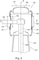
- is a schematic cross-sectional view of a shield for a terminal of a high-voltage device according to an embodiment of the disclosure;
- Fig. 3A-3B
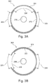
- are schematic cross-sectional views of a shield for a terminal of a high-voltage device according to an embodiment of the disclosure;
- Fig. 4A-4C
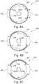
- are schematic cross-sectional views of a shield for a terminal of a high-voltage device according to an embodiment of the disclosure; and
- Fig. 5
- is a flowchart of a method installing a high-voltage bushing according to an embodiment of the disclosure.
- Reference will now be made in detail to the various embodiments, one or more examples of which are illustrated in each figure. Each example is provided by way of explanation and is not meant as a limitation. For example, features illustrated or described as part of one embodiment can be used on or in conjunction with any other embodiment to yield yet a further embodiment. It is intended that the present disclosure includes such modifications and variations.
- Within the following description of the drawings, the same reference numbers refer to the same or to similar components. Generally, only the differences with respect to the individual embodiments are described. Unless specified otherwise, the description of a part or aspect in one embodiment can be applied to a corresponding part or aspect in another embodiment as well.
-
Fig. 1 exemplarily shows a cross-sectional view of atransformer 100 according to an embodiment of the present disclosure. The transformer includes at least oneelectrical bushing 200 according to any embodiments described herein. The transformer may be, for example, a medium-or high-voltage transformer, particularly a high-voltage transformer. In the context of the present disclosure, the term "medium-voltage" may refer to a voltage of at least 1 kV and up to 52 kV. Further, the term "high-voltage" in the context of the present disclosure may refer to a voltage of at least 52 kV. - The
transformer 100 may, for example, include afirst region 101 and asecond region 102. Thefirst region 101 andsecond region 102 may be separated by amounting surface 105. The at least oneelectrical bushing 200 may be mounted to mountingsurface 105 such that aconductor 205 of the at least oneelectrical bushing 200 may pass through mountingsurface 105. In other words, at least oneelectrical bushing 200 may be mounted in a transformer such that aconductor 205 may pass fromfirst region 101 tosecond region 102. The at least oneelectrical bushing 200 may include abody element 204, through whichconductor 205 passes.Body element 204 may be filled with an isolation medium, for example oil.Second region 102 may be filled with an isolation medium, for example oil, wherein the at least oneelectrical bushing 200 is partially immersed therein. - As exemplarily shown in
Fig. 1 , the at least oneelectrical bushing 200 is provided with anupper terminal 206 and alower terminal 207. Upper andlower terminals conductor 205.Transformer 100 may further include at least oneelectrical interconnect upper terminal 206 andlower terminal 207. The at least oneelectrical interconnect electrical interconnect - In the example shown in
Fig. 1 ,transformer 100 includes a lateralelectrical interconnect 103 and an axialelectrical interconnect 104. Lateralelectrical interconnect 103 is shown to be mounted toupper terminal 206 such that lateralelectrical interconnect 103 extends in a lateral direction with respect to the at least oneelectrical bushing 200. Axialelectrical interconnect 104 is shown to be mounted tolower terminal 207 such that axialelectrical interconnect 104 extends in an axial direction with respect to the at least oneelectrical bushing 200. The configuration ofelectrical interconnects Fig. 1 is provided only as an example, andtransformer 100 may have any combination ofelectrical bushing 200 andelectrical interconnects transformer 100 may include an axial electrical interconnect mounted toupper terminal 206 and a lateral electrical interconnect mounted tolower terminal 207. As a further example,transformer 100 may include two lateral electrical interconnects each mounted toupper terminal 206 andlower terminal 207, respectively. - The at least one
electrical bushing 200 includes at least one shield for shieldingupper terminal 206 andlower terminal 207. In this example, anupper shield 201 is provided for shieldingupper terminal 206 and alower shield 202 is provided for shieldinglower terminal 207. It is clear from this example that, due to the configuration of lateralelectrical interconnect 103 and axialelectrical interconnect 104, the upper andlower shields upper shield 201 is provided with a lateral opening for lateralelectrical interconnect 103 to pass through, whilelower shield 202 is provided with an axial opening for axialelectrical interconnect 104 to pass through. - Modularity of parts have advantageous properties, as modular parts allow for minimizing the number of different parts, hence reducing cost of manufacture and installation. However, simply providing the same number openings in the same positions for upper and
lower shields Fig. 1 , for example, upper andlower shields lower terminals upper shield 201 does not require an axial opening andlower shield 202 does not require a lateral opening. Therefore, the electrical shielding performance of such a modular part would be compromised. - Referring now to
Fig. 2 , an aspect of the present disclosure provides ashield 300 for aterminal 206 of a high-voltageelectrical device 200. Theshield 300 includes afirst shield element 301 having at least oneaxial opening 304 and at least one firstlateral opening 305, and at least onesecond shield element second shield element axial opening 304 and the at least one firstlateral opening 305. -
First shield element 301 includes at least oneaxial opening 304. At least oneaxial opening 304 is provided so that anelectrical interconnect 103 may be attached toterminal 206 such thatelectrical interconnect 103 extends in an axial direction, i.e. in the direction of longitudinal axis R, such thatelectrical interconnect 103 passes through at least oneaxial opening 304. At least oneaxial opening 304 may also be provided so that terminal 206 may pass therethrough, for example, on an axial end offirst shield element 301 which corresponds to the side whereelectrical bushing 200 is provided. -
First shield element 301 further includes at least one firstlateral opening 305. At least one firstlateral opening 305 is provided so that anelectrical interconnect 103 may be attached toterminal 206 such thatelectrical interconnect 103 extends in a lateral direction, i.e. in a direction substantially perpendicular to longitudinal axis R, such thatelectrical interconnect 103 passes through at least one firstlateral opening 305. - The at least
axial opening 304 and at least one firstlateral opening 305 may be configured such that theopening opening opening opening opening opening opening opening - As exemplarily shown in
Fig. 2 , one firstlateral opening 305 on the left side ofFig. 2 is shown to be in an open state, whereby over 80% of the area of the firstlateral opening 305 is uncovered. Another firstlateral opening 305 on the right side ofFig. 2 is shown to be in a closed state, whereby over 80% of the area of the firstlateral opening 305 is covered. Oneaxial opening 304 at the top side ofFig. 2 is shown to be in a closed state, or in this case, a substantially closed state, whereby over 80% of the area of theaxial opening 304 is covered. -
Shield 300 further includes at least onesecond shield element Second shield element axial opening 304 and/or the at least one firstlateral opening 305 is in an open state or a closed state. As exemplarily shown inFig. 2 ,second shield lateral opening 305 on the left side ofFig. 2 is in an open state, another firstlateral opening 305 on the right side ofFig. 2 is in a closed state, and oneaxial opening 304 is an substantially closed state. -
First shield element 301 andsecond shield element 302 are arranged such that the first andsecond shield elements second shield elements second shield elements axial opening 304 and at least onelateral opening 305 are provided in an open state.First shield element 301 andsecond shield element 302 may be fastened to one another usingfasteners 307.Fasteners 307 may be removable such thatfirst shield element 301 andsecond shield element 302 may be moved from a first position to a second position. - As exemplarily shown in
Figs. 1 and2 , the high-voltage electrical device is shown to be anelectrical bushing 200 having at least oneterminal 206. However, the present disclosure is not limited to anelectrical bushing 200. The high-voltage electrical device may be any high-voltage electrical device having a terminal which requires a shield. For example, the high-voltage electrical device may be any high-voltage electrical distribution component including, but not limited to, electrical breakers, lightning arrestors, electrical relays, bus bars, etc. - First and
second shield element second shield element second shield element second shield element second shield element second shield element - According to an embodiment, which may be combined with other embodiments described herein, shield 300 may be at the same electrical potential as
terminal 206. In the context of the present disclosure, the term "same electrical potential" may refer to approximately the same electrical potential. For example, terminal 206 may be at a voltage of 100 kV, whileshield 300 may be at a voltage of approximately 100 kV, for example 98 kV. Preferably, shield 300 may be at a voltage within ± 10 % of the voltage ofterminal 206. Particularly,shield 300 may be electrically connected to any one ofterminal 206,conductor 205 orelectrical interconnect 103. Due to the approximately same electrical potential ofterminal 206 andshield 300, terminal 206 is electrically shielded such that, despite being at a high electrical potential, terminal 206 is subjected to no, or very little, electrical stress. - Reference will now be made to
Figs. 3A and 3B , which show cross-sectional top views ofshield 300 according to embodiments described herein. Particularly,Figs. 3A and 3B show cross-sectional views through section line B-B as shown inFig. 2 .Electrical interconnect 103 is not shown inFigs. 3A and 3B for clarity. - According to an embodiment, which may be combined with other embodiments described herein, the at least one
second shield element 302 may be a lateral shield element configured for opening or closing the at least one firstlateral opening 304, and thefirst shield element 301 and thelateral shield element 302 are arranged concentrically to one another.First shield element 301 andlateral shield element 302 may be rotationally symmetrical about a common axis, for example, longitudinal axis R. Particularly,first shield element 301 andlateral shield element 302 may have a cylindrical shape. Alternatively,first shield element 301 andlateral shield element 302 may have a spherical shape, or a partially spherical shape. - As exemplarily shown in
Figs. 2 ,3A and 3B ,first shield element 301 may be arranged such thatfirst shield element 301 is an outer shield whilesecond shield element 302 may be arranged such thatsecond shield 302 element is an inner shield. However, the present disclosure is not limited to this arrangement. For example,first shield 301 element andsecond shield element 302 may be arranged such thatfirst shield 301 is an inner shield whilesecond shield 302 is an outer shield. - The movement between a first shield position and a second shield position may be achieved by relative rotation between
first shield element 301 andlateral shield element 302. Sincefirst shield element 301 andlateral shield element 302 may be arranged concentrically to each other, it follows thatfirst shield element 301 andlateral shield element 302 may be rotated within each other from a first shield position to a second shield position. In the examples shown inFigs. 3A and 3B ,first shield element 301 is maintained in a stationary position whilelateral shield element 302 is rotated about longitudinal axis R. However, the present disclosure is not limited to this arrangement. For example,lateral shield element 302 may be maintained in a stationary position whilefirst shield element 301 is rotated about longitudinal axis R. - According to an embodiment, which may be combined with other embodiments described herein,
lateral shield element 302 may further include at least one second lateral opening 306, wherein the at least one firstlateral opening 305 is in an open state when the at least one firstlateral opening 305 is aligned with the at least one second lateral opening 306, and wherein the at least one firstlateral opening 305 is in a closed state when the at least one firstlateral opening 305 is misaligned with the at least one secondlateral opening 306. - The at least one second lateral opening 306 may be a portion of
lateral shield element 306 which has been removed. The at least one second lateral opening 306 may correspond to the size and/or shape of the at least one firstlateral opening 305. Alternatively, the at least one second lateral opening 306 may be larger than the at least one firstlateral opening 305. When the at least one firstlateral opening 305 and the at least one second lateral opening 306 are aligned with each other, the opening is therefore in an open state. The term "aligned" in the context of the present disclosure refers to a substantial overlap of the respective areas of the at least one firstlateral opening 305 and the at least one secondlateral opening 306. Similarly, when the at least one firstlateral opening 305 and the at least one second lateral opening 306 are misaligned with each other, the opening is therefore in a closed state. The term "misaligned" in the context of the present disclosure refers to a substantial non-overlap of the respective areas of the at least one firstlateral opening 305 and the at least one secondlateral opening 306. - As exemplarily shown in
Figs. 3A and 3B ,first shield element 301 includes two firstlateral openings 305 arranged at approximately opposite sides offirst shield element 301.Lateral shield element 302 includes one secondlateral opening 306.Fig. 3A shows a first configuration wherein the secondlateral opening 306 is misaligned with both firstlateral openings 305. In this configuration, both of the two firstlateral openings 305 are in a closed state. - Rotating
lateral shield element 302 about longitudinal axis R allows for the configuration ofshield 300 to be changed. For example,Fig. 3B shows a second configuration whereinlateral shield element 302 has been rotated approximately 90° in an anti-clockwise direction about longitudinal axis R. In this configuration, one of the two firstlateral openings 305 is now aligned with the second lateral opening 306 so that one of the two firstlateral openings 305 is in an open state. The other one of the two firstlateral openings 305 remains misaligned with secondlateral opening 306 such that the other one of the two firstlateral openings 305 remains in a closed state. In the configuration shown inFig. 3B , anelectrical interconnect 103 may now be attached toterminal 206 so that it extends laterally through one of the two firstlateral openings 305. - It follows that the
lateral shield element 302, from the position shown inFig. 3A , may alternatively be rotated approximately 90° in a clockwise direction about longitudinal axis R such that the other one of the twolateral openings 305 is changed to an open state. - Reference will now be made to
Figs. 4A, 4B and 4C , which show cross-sectional top views ofshield 300 according to embodiments described herein. Particularly,Figs. 4A, 4B and 4C show cross-sectional views through section line B-B as shown inFig. 2 .Electrical interconnect 103 is not shown inFigs. 4A, 4B and 4C for clarity. - Similarly to the example shown in
Figs. 3A and 3B , the example shown inFigs. 4A, 4B and 4C show another example of an arrangement of openings such thatshield 300 may be reconfigured. Referring firstly toFig. 4A ,first shield element 301 is again provided with two firstlateral openings 305 arranged at approximately opposite sides offirst shield element 301. However, in this case,lateral shield element 302 is provided with a small secondlateral opening 306A and a large secondlateral opening 306B. In the configuration shown inFig. 4A , neither one of the small or largesecond lateral openings lateral openings 305. Therefore, in this first configuration, both of the two firstlateral openings 305 are in a closed state. -
Fig. 4B shows a second configuration whereinlateral shield element 302 has been rotated in a clockwise direction about longitudinal axis R. In this second configuration, one of the two firstlateral openings 305 is now aligned with the large secondlateral opening 306B so that one of the two firstlateral openings 305 is in an open state. The other one of the two firstlateral openings 305 remains misaligned with small secondlateral opening 306A such that the other one of the two firstlateral openings 305 remains in a closed state. In the configuration shown inFig. 4B , anelectrical interconnect 103 may now be attached toterminal 206 so that it extends laterally through one of the two firstlateral openings 305. -
Fig. 4C shows a third configuration whereinlateral shield element 302 has been rotated further in a clockwise direction about longitudinal axis R. In this third configuration, one of the two firstlateral openings 305 is still aligned with the large secondlateral opening 306B so that one of the two firstlateral openings 305 is in an open state, just like inFig. 4B . However, the other one of the two firstlateral openings 305 is now aligned with small secondlateral opening 306A such that the other one of the two firstlateral openings 305 is also in an open state. In the configuration shown inFig. 4C , a firstelectrical interconnect 103 may now be attached toterminal 206 so that it extends laterally through one of the two firstlateral openings 305, and a secondelectrical interconnect 103 may also be attached toterminal 206 such that it extends laterally through the other one of the two firstlateral openings 305. - In the present disclosure, the arrangement of first and
second openings Figs. 3A, 3B ,4A, 4B and 4C . Rather, any arrangement of first andsecond openings - According to an embodiment, which may be combined with other embodiments described herein, the at least one second shield element is an
axial shield element 303 configured for opening or closing the at least oneaxial opening 304. As exemplarily shown inFig. 2 ,axial shield element 303 may have a cap shape such thataxial shield element 303 substantially covers the at least oneaxial opening 304. - In order to be configured to open or close the at least one
axial opening 304,axial shield element 303 may be a removable cap, i.e.axial shield element 303 may be in a mounted position or in an unmounted position.Fig. 2 exemplarily showsaxial shield element 303 in a mounted position. When in a mounted position,axial shield element 303 is configured for closing the at least oneaxial opening 304, i.e. theaxial opening 304 is in a closed state such thatterminal 206 is electrically shielded. Removingaxial shield element 303, i.e. configuringaxial shield 303 into an unmounted position, configures theaxial opening 304 in an open state. Whenaxial shield element 303 is in an unmounted position andaxial opening 304 is in an open state, anelectrical interconnect 103 may be mounted toterminal 206 such thatelectrical interconnect 103 extends in an axial direction throughaxial opening 304, i.e. in the direction of longitudinal axis R. -
Axial shield element 303 may include a fastening means. The fastening means may be quickly and efficiently operated such thataxial shield element 303 may be quickly and efficiently mounted and unmounted as required. For example,axial shield element 303 may include at least one screw or bolt which may be removed so thataxial shield element 303 may be unmounted. Preferably,axial shield element 303 may include a bayonet mount as the fastening means. -
Axial shield element 303 may be mounted to at least one offirst shield element 301,lateral shield element 302, a part ofbody element 204 at a high voltage potential,conductor 205 andterminal 206. For example,axial shield element 303 may be mounted directly toconductor 205 such thataxial shield element 303 is at the same electrical potential asconductor 205, while leaving terminal 206 free for mounting anelectrical interconnect 103. Alternatively,axial shield element 303 may be mounted tofirst shield element 301 orlateral shield element 302 such thataxial shield element 303 is at the same electrical potential asfirst shield element 301 and/orlateral shield element 302. - According to yet a further aspect of the present disclosure, a
method 400 of installing a high-voltage bushing is provided. The high-voltage bushing includes a shield according to the aspects and embodiments described herein. Reference is now made toFig. 5 , which shows a flowchart ofmethod 400.Method 400 commences atblock 401.Method 400 includes mounting the high-voltage bushing inblock 402, configuring the at least one axial opening and/or the at least one first lateral opening in an open or closed state inblock 403, and terminating the high-voltage bushing inblock 404. Themethod 400 concludes atblock 405. - In
block 402,method 400 includes mounting the high-voltage bushing. Mounting the high-voltage bushing 200 may involve fastening a mountingflange 203 to a mountingsurface 105, for example, the housing of atransformer 100. The mountingflange 203 may be fastened such that the electrical bushing passes through mountingsurface 105. Mountingflange 203 may include a number of flange mounting holes. Fasteners may be provided for securely fastening mountingflange 203 to mountingsurface 105 such that the fasteners pass through the flange mounting holes and the mountingsurface 105. - In
block 403,method 400 includes configuring the at least one axial opening and/or the at least one first lateral opening in an open or closed state. The configuring may involve moving at least one of thefirst shield element 301 and the at least onesecond shield element fasteners 307 prior to moving at least one of thefirst shield element 301 and the at least onesecond shield element re-attaching fasteners 307 after moving at least one of thefirst shield element 301 and the at least onesecond shield element - According to an embodiment, which may be combined with other embodiments described herein, configuring the at least one first lateral opening in
block 403 includes relative rotation between the first shield element and the lateral shield element. The relative rotation may include either one of rotatingfirst shield element 301 and maintaininglateral shield element 302 in a stationary position, or rotatinglateral shield element 302 and maintainingfirst shield element 301 in a stationary position.First shield element 301 may include at least one firstlateral opening 305, andlateral shield element 302 may include at least one secondlateral opening 306. Relative rotation betweenfirst shield element 301 andlateral shield element 302 allows for the positions of the at least one firstlateral opening 305 and the at least one second lateral opening 306 to be configured. When shields 301, 302 are rotated relative to one another such that at least one firstlateral opening 305 and at least one second lateral opening 306 are aligned, the at least one firstlateral opening 305 is in an open state. Similarly, when shields 301, 302 are rotated relative to one another such that the at least one firstlateral opening 305 and the at least one second lateral opening 306 are misaligned, the at least one first lateral opening is in a closed state. - According to an embodiment, which may be combined with other embodiments described herein, the configuring at least one axial opening in
block 403 includes mounting or removing the axial shield element. Mountingaxial shield element 303 configures the at least one axial opening in a closed state. Removingaxial shield element 303 configures the at least one axial opening in an open state. Mounting or removingaxial shield element 303 may include mounting or removing a fastening means, wherein the fastening means is configured for fasteningaxial shield element 303. For example, the fastening means may be a bayonet mount configured for detachably mountingaxial shield element 303 tofirst shield element 301. - In
block 404, themethod 400 includes terminating the high-voltage bushing. In the context of the present disclosure, the term "terminating" refers to mounting at least oneelectrical interconnect 103 to at least one terminal 206 such thatelectrical interconnect 103 and terminal 206 are electrically connected. For example, terminal 206 may include a threaded portion andelectrical interconnect 103 may include an eyelet portion. The high-voltage bushing may be "terminated" by mounting the eyelet portion ofelectrical interconnect 103 toterminal 206 and fastening the eyelet portion to terminal 206 with a nut engaging with the threaded portion.Electrical interconnect 103 may be mounted such thatelectrical interconnect 103 extends in an axial direction, i.e. substantially in the direction of longitudinal axis R. Alternatively,electrical interconnect 103 may be mounted such thatelectrical interconnect 103 extends in a lateral direction, i.e. substantially in a direction perpendicular to longitudinal axis R. - Terminating the high-voltage bushing may include electrically connecting at least one
terminal 206 of high-voltage bushing 200 to another electrical device. For example, the high-voltage bushing 200 may be electrically connected to a transformer, an electrical breaker, or a bus bar. - According to an embodiment, which may be combined with other embodiments described herein, the terminating the high-voltage bushing in
block 404 includes mounting at least one electrical interconnect to the terminal such that the at least one electrical interconnect passes through an open one of the at least one axial opening and/or the at least one first lateral opening. For example, in the case where at least oneelectrical interconnect 103 extends in a lateral direction, i.e. substantially in the direction perpendicular to longitudinal axis R,electrical interconnect 103 passes through the respective first lateral opening which has been configured in an open state. Similarly, in the case where at least oneelectrical interconnect 103 extends in an axial direction, i.e. substantially in the direction of longitudinal axis R,electrical interconnect 103 passes through the respective axial opening which has been configured in an open state. - While the foregoing is directed to aspects and embodiments of the disclosure, other and further embodiments of the disclosure may be devised without departing from the basic scope thereof, and the scope thereof is determined by the claims that follow.
Claims (15)
- Shield (300) for a terminal (206) of a high-voltage electrical device (200) comprising:a first shield element (301) having at least one axial opening (304) and at least one first lateral opening (305); andat least one second shield element (302, 303);wherein the at least one second shield element (302, 303) may be positioned so that the at least one axial opening (304) and/or the at least one first lateral opening (305) is in an open state or a closed state.
- Shield (300) according to claim 1, wherein the high-voltage electrical device (200) is a high-voltage bushing (200), particularly a high-voltage bushing (200) for a transformer (100).
- Shield (300) according to any one of claims 1 and 2, wherein the at least one second shield element is a lateral shield element (302) configured for opening or closing the at least one first lateral opening (305), and the first shield element (301) and the lateral shield element (302) are arranged concentrically to one another.
- Shield (300) according to claim 3, wherein the at least one first lateral opening (305) is changed between the open state and the closed state by relative rotation between the first shield element (301) and the lateral shield element (302).
- Shield (300) according to any one of claims 3 and 4, wherein the lateral shield element (302) comprises at least one second lateral opening (306), wherein the at least one first lateral opening (305) is in the open state when the at least one first lateral opening (305) is aligned with the at least one second lateral opening (306), and wherein the at least one first lateral opening (305) is in the closed state when the at least one first lateral opening (305) is misaligned with the at least one second lateral opening (306).
- Shield (300) according to any one of claims 3 to 5, wherein the first shield element (301) comprises at least two first lateral openings (305), and the lateral shield element (302) may be positioned such that a first one of the at least two first lateral openings (305) is in an open state and a second one of the at least two first lateral openings (305) is in a closed state.
- Shield (300) according to any one of claims 1 to 6, wherein the at least one second shield element is an axial shield element (303) configured for opening or closing the at least one axial opening (304).
- Shield (300) according to any one of claims 1 to 7, wherein the shield (300) has the same electrical potential as the terminal (206).
- High-voltage electrical bushing (200) comprising a shield (300) according to any one of claims 1 to 8.
- High-voltage electrical bushing (200) according to claim 9, wherein at least one electrical interconnect (103) can be mounted to the terminal (206) so that the at least one electrical interconnect (103) extends in a lateral direction or an axial direction.
- Transformer (100) comprising at least one high-voltage electrical bushing (200) according to any one of claims 9 and 10.
- Method (400) of installing a high-voltage bushing (200) having a shield (300) according to any one of claims 1 to 8, the method (400) comprising:mounting (402) the high-voltage bushing (200);configuring (403) the at least one axial opening (304) and/or the at least one first lateral opening (305) in an open state or a closed state; and
- Method (400) according to claim 12, wherein the high-voltage bushing (200) has a shield (300) according to any one of claims 5 to 9, wherein configuring (403) the at least one first lateral opening (305) comprises relative rotation between the first shield element (301) and the lateral shield element (302).
- Method (400) according to any of claims 12 and 13, wherein the high-voltage bushing (200) has a shield (300) according to any one of claims 7 and 8, wherein configuring (403) at least one axial opening (304) comprises mounting or removing the axial shield element (303).
- Method (400) according to any of claims 12 to 14, wherein terminating (404) the high-voltage bushing (200) comprises mounting at least one electrical interconnect (103) to the terminal (206) such that the at least one electrical interconnect (103) passes through the at least one axial opening (304) and/or the at least one first lateral opening (305).
Priority Applications (5)
| Application Number | Priority Date | Filing Date | Title |
|---|---|---|---|
| EP18191746.9A EP3618086B1 (en) | 2018-08-30 | 2018-08-30 | Shield for a terminal of a high-voltage electrical device and method for operating the same |
| CN201980056137.XA CN112673437B (en) | 2018-08-30 | 2019-08-28 | Shield for high voltage electrical equipment terminals and method for operating the shield |
| KR1020217005245A KR102338148B1 (en) | 2018-08-30 | 2019-08-28 | Shields for terminals of high voltage electrical devices and methods of operating them |
| PCT/EP2019/072980 WO2020043784A1 (en) | 2018-08-30 | 2019-08-28 | Shield for a terminal of a high-voltage electrical device and method for operating the same |
| US17/271,992 US11823815B2 (en) | 2018-08-30 | 2019-08-28 | Shield for a terminal of a high-voltage electrical device and method for operating the same |
Applications Claiming Priority (1)
| Application Number | Priority Date | Filing Date | Title |
|---|---|---|---|
| EP18191746.9A EP3618086B1 (en) | 2018-08-30 | 2018-08-30 | Shield for a terminal of a high-voltage electrical device and method for operating the same |
Publications (2)
| Publication Number | Publication Date |
|---|---|
| EP3618086A1 true EP3618086A1 (en) | 2020-03-04 |
| EP3618086B1 EP3618086B1 (en) | 2021-04-28 |
Family
ID=63449391
Family Applications (1)
| Application Number | Title | Priority Date | Filing Date |
|---|---|---|---|
| EP18191746.9A Active EP3618086B1 (en) | 2018-08-30 | 2018-08-30 | Shield for a terminal of a high-voltage electrical device and method for operating the same |
Country Status (5)
| Country | Link |
|---|---|
| US (1) | US11823815B2 (en) |
| EP (1) | EP3618086B1 (en) |
| KR (1) | KR102338148B1 (en) |
| CN (1) | CN112673437B (en) |
| WO (1) | WO2020043784A1 (en) |
Citations (4)
| Publication number | Priority date | Publication date | Assignee | Title |
|---|---|---|---|---|
| DE2554460A1 (en) * | 1975-01-17 | 1976-07-22 | Smit Nijmegen Bv | Joining of HV transformer taps and cable - uses end of winding in tubular stem of electrically conducting receptacle (NL200776) |
| JPH0617218U (en) * | 1992-07-28 | 1994-03-04 | 三菱電機株式会社 | Electric shield device for oil-filled induction equipment |
| EP2028665A1 (en) * | 2007-08-22 | 2009-02-25 | Pioch | Bushing assembly designed to be mounted through an orifice in the wall of an electricity transformer. |
| WO2010066984A1 (en) * | 2008-12-12 | 2010-06-17 | Pioch | Busbar bushing with an orientationally adjustable protective casing dedicated to the connector |
Family Cites Families (15)
| Publication number | Priority date | Publication date | Assignee | Title |
|---|---|---|---|---|
| US4222625A (en) | 1978-12-28 | 1980-09-16 | Amerace Corporation | High voltage electrical connector shield construction |
| JPH0744116B2 (en) | 1988-06-21 | 1995-05-15 | 三菱電機株式会社 | Electrical equipment |
| EP0383988B1 (en) | 1989-02-20 | 1993-08-11 | Siemens Aktiengesellschaft | High-voltage lead-through for oil-cooled electric devices |
| US6218627B1 (en) | 1998-02-04 | 2001-04-17 | Hitachi, Ltd. | Bushing |
| JP2000269043A (en) | 1999-03-17 | 2000-09-29 | Meidensha Corp | Transformer |
| US6255597B1 (en) * | 2000-02-25 | 2001-07-03 | Tyco Electronics Corporation | Wildlife guard for electrical insulator bushings |
| BRPI0620938A2 (en) | 2005-12-30 | 2011-11-29 | Abb Technology Ag | high voltage bushing and high voltage device comprising this bushing |
| WO2008109109A1 (en) | 2007-03-06 | 2008-09-12 | Tyco Electronics Corporation | High voltage shielded electrical connector assembly |
| KR101198973B1 (en) | 2008-10-28 | 2012-11-07 | 현대중공업 주식회사 | Shield combination device of the ultra high voltage transformer |
| US8426729B2 (en) * | 2009-10-08 | 2013-04-23 | Tyco Electronics Corporation | Wildlife guard assemblies, modular systems and methods for using the same |
| KR101034878B1 (en) | 2009-11-19 | 2011-05-17 | 한국전기연구원 | High voltage bushings with improved field relaxation and insulation |
| CA2789077C (en) * | 2010-02-05 | 2017-12-19 | Cantega Technologies Inc. | Apparatus and method for protecting a component of an electrical power transmission system |
| EP2591481B1 (en) | 2010-07-08 | 2018-10-31 | ABB Research Ltd. | High voltage shielding device and a system comprising the same |
| US9960586B2 (en) * | 2013-07-12 | 2018-05-01 | Cantega Technologies Inc. | Electrical power transmission protectors with component grippers, and related methods |
| CN107677916B (en) | 2017-09-04 | 2020-07-14 | 中国电力科学研究院 | High-voltage bushing end shield grounding shield and high-voltage bushing end shield |
-
2018
- 2018-08-30 EP EP18191746.9A patent/EP3618086B1/en active Active
-
2019
- 2019-08-28 KR KR1020217005245A patent/KR102338148B1/en active Active
- 2019-08-28 CN CN201980056137.XA patent/CN112673437B/en active Active
- 2019-08-28 US US17/271,992 patent/US11823815B2/en active Active
- 2019-08-28 WO PCT/EP2019/072980 patent/WO2020043784A1/en not_active Ceased
Patent Citations (4)
| Publication number | Priority date | Publication date | Assignee | Title |
|---|---|---|---|---|
| DE2554460A1 (en) * | 1975-01-17 | 1976-07-22 | Smit Nijmegen Bv | Joining of HV transformer taps and cable - uses end of winding in tubular stem of electrically conducting receptacle (NL200776) |
| JPH0617218U (en) * | 1992-07-28 | 1994-03-04 | 三菱電機株式会社 | Electric shield device for oil-filled induction equipment |
| EP2028665A1 (en) * | 2007-08-22 | 2009-02-25 | Pioch | Bushing assembly designed to be mounted through an orifice in the wall of an electricity transformer. |
| WO2010066984A1 (en) * | 2008-12-12 | 2010-06-17 | Pioch | Busbar bushing with an orientationally adjustable protective casing dedicated to the connector |
Also Published As
| Publication number | Publication date |
|---|---|
| CN112673437A (en) | 2021-04-16 |
| KR20210034651A (en) | 2021-03-30 |
| US20210319932A1 (en) | 2021-10-14 |
| US11823815B2 (en) | 2023-11-21 |
| KR102338148B1 (en) | 2021-12-14 |
| WO2020043784A1 (en) | 2020-03-05 |
| EP3618086B1 (en) | 2021-04-28 |
| CN112673437B (en) | 2022-03-01 |
Similar Documents
| Publication | Publication Date | Title |
|---|---|---|
| DE112010005871B4 (en) | Gas-insulated electrical appliance | |
| EP0744803A2 (en) | Isolator switch for metal-clad, high voltage switchgear | |
| DE102014104541B4 (en) | control panel | |
| CN101902023B (en) | Electricity conductor for a high current insulating casing | |
| EP3618086B1 (en) | Shield for a terminal of a high-voltage electrical device and method for operating the same | |
| EP2117016A1 (en) | Draw rod mounting arrangement for a high voltage bushing, high voltage bushing comprising such arrangement and high voltage device comprising bushing with such arrangement | |
| EP1709720A2 (en) | Compressed gas insulated separating switch component and leadthrough arrangement | |
| EP3987298B1 (en) | Measuring an electrical voltage on a metal-encapsulated switchgear | |
| EP1696444B1 (en) | Summation current transformer | |
| US4477692A (en) | High voltage terminal bushing for electrical apparatus | |
| CA1334855C (en) | Electrical apparatus with an in-tank electromagnetic shield | |
| EP3703192A1 (en) | Terminal adapter for an electrical bushing, electrical bushing having said terminal adapter, and method for mounting thereof | |
| EP2930804B1 (en) | Method for operating a switch assembly | |
| CN102985986B (en) | High voltage shielding device and system including the device | |
| DE102019213995B4 (en) | Measuring arrangement for measuring a voltage potential on a conductor in a power switching device and corresponding power switching device | |
| DE19523074A1 (en) | Support insulator | |
| DE102006040037A1 (en) | Connection module with an encapsulating housing | |
| EP0718942B1 (en) | High voltage installation | |
| DE102006001237A1 (en) | Three-phase insulated high voltage switch gear, has supporting unit with insulating connector provided between circuit breaker and bus bar region, where connector is formed such that circuit breaker is stabilized in its position | |
| WO2021023363A1 (en) | Connecting structure having a uhf antenna for a gas-insulated switchgear installation | |
| DE8816894U1 (en) | Metal-enclosed, pressure-gas-insulated high-voltage switchgear with insulated earthing switch | |
| EP3979278B1 (en) | Current transformer module for a switchgear and corresponding switchgear | |
| US11251003B2 (en) | Insulating support assembly for a circuit breaker | |
| US20210376577A1 (en) | Bus bar connecting device, switchgear, and method for connecting a bus bar connecting device | |
| EP3276647B1 (en) | Grounding unit for a switching system |
Legal Events
| Date | Code | Title | Description |
|---|---|---|---|
| PUAI | Public reference made under article 153(3) epc to a published international application that has entered the european phase |
Free format text: ORIGINAL CODE: 0009012 |
|
| STAA | Information on the status of an ep patent application or granted ep patent |
Free format text: STATUS: THE APPLICATION HAS BEEN PUBLISHED |
|
| AK | Designated contracting states |
Kind code of ref document: A1 Designated state(s): AL AT BE BG CH CY CZ DE DK EE ES FI FR GB GR HR HU IE IS IT LI LT LU LV MC MK MT NL NO PL PT RO RS SE SI SK SM TR |
|
| AX | Request for extension of the european patent |
Extension state: BA ME |
|
| RAP1 | Party data changed (applicant data changed or rights of an application transferred) |
Owner name: ABB SCHWEIZ AG |
|
| STAA | Information on the status of an ep patent application or granted ep patent |
Free format text: STATUS: REQUEST FOR EXAMINATION WAS MADE |
|
| RAP1 | Party data changed (applicant data changed or rights of an application transferred) |
Owner name: ABB POWER GRIDS SWITZERLAND AG |
|
| 17P | Request for examination filed |
Effective date: 20200715 |
|
| RBV | Designated contracting states (corrected) |
Designated state(s): AL AT BE BG CH CY CZ DE DK EE ES FI FR GB GR HR HU IE IS IT LI LT LU LV MC MK MT NL NO PL PT RO RS SE SI SK SM TR |
|
| GRAP | Despatch of communication of intention to grant a patent |
Free format text: ORIGINAL CODE: EPIDOSNIGR1 |
|
| STAA | Information on the status of an ep patent application or granted ep patent |
Free format text: STATUS: GRANT OF PATENT IS INTENDED |
|
| INTG | Intention to grant announced |
Effective date: 20201124 |
|
| GRAS | Grant fee paid |
Free format text: ORIGINAL CODE: EPIDOSNIGR3 |
|
| GRAA | (expected) grant |
Free format text: ORIGINAL CODE: 0009210 |
|
| STAA | Information on the status of an ep patent application or granted ep patent |
Free format text: STATUS: THE PATENT HAS BEEN GRANTED |
|
| RIN1 | Information on inventor provided before grant (corrected) |
Inventor name: GARGANO, TERESA Inventor name: VILLANO, DANIELE Inventor name: FREI, KARL Inventor name: MEYER, FRANCESCA |
|
| AK | Designated contracting states |
Kind code of ref document: B1 Designated state(s): AL AT BE BG CH CY CZ DE DK EE ES FI FR GB GR HR HU IE IS IT LI LT LU LV MC MK MT NL NO PL PT RO RS SE SI SK SM TR |
|
| REG | Reference to a national code |
Ref country code: GB Ref legal event code: FG4D |
|
| REG | Reference to a national code |
Ref country code: CH Ref legal event code: EP |
|
| REG | Reference to a national code |
Ref country code: AT Ref legal event code: REF Ref document number: 1388026 Country of ref document: AT Kind code of ref document: T Effective date: 20210515 |
|
| REG | Reference to a national code |
Ref country code: DE Ref legal event code: R096 Ref document number: 602018016111 Country of ref document: DE |
|
| REG | Reference to a national code |
Ref country code: IE Ref legal event code: FG4D |
|
| REG | Reference to a national code |
Ref country code: LT Ref legal event code: MG9D |
|
| REG | Reference to a national code |
Ref country code: AT Ref legal event code: MK05 Ref document number: 1388026 Country of ref document: AT Kind code of ref document: T Effective date: 20210428 |
|
| PG25 | Lapsed in a contracting state [announced via postgrant information from national office to epo] |
Ref country code: FI Free format text: LAPSE BECAUSE OF FAILURE TO SUBMIT A TRANSLATION OF THE DESCRIPTION OR TO PAY THE FEE WITHIN THE PRESCRIBED TIME-LIMIT Effective date: 20210428 Ref country code: LT Free format text: LAPSE BECAUSE OF FAILURE TO SUBMIT A TRANSLATION OF THE DESCRIPTION OR TO PAY THE FEE WITHIN THE PRESCRIBED TIME-LIMIT Effective date: 20210428 Ref country code: HR Free format text: LAPSE BECAUSE OF FAILURE TO SUBMIT A TRANSLATION OF THE DESCRIPTION OR TO PAY THE FEE WITHIN THE PRESCRIBED TIME-LIMIT Effective date: 20210428 Ref country code: AT Free format text: LAPSE BECAUSE OF FAILURE TO SUBMIT A TRANSLATION OF THE DESCRIPTION OR TO PAY THE FEE WITHIN THE PRESCRIBED TIME-LIMIT Effective date: 20210428 Ref country code: BG Free format text: LAPSE BECAUSE OF FAILURE TO SUBMIT A TRANSLATION OF THE DESCRIPTION OR TO PAY THE FEE WITHIN THE PRESCRIBED TIME-LIMIT Effective date: 20210728 Ref country code: NL Free format text: LAPSE BECAUSE OF FAILURE TO SUBMIT A TRANSLATION OF THE DESCRIPTION OR TO PAY THE FEE WITHIN THE PRESCRIBED TIME-LIMIT Effective date: 20210428 |
|
| PG25 | Lapsed in a contracting state [announced via postgrant information from national office to epo] |
Ref country code: GR Free format text: LAPSE BECAUSE OF FAILURE TO SUBMIT A TRANSLATION OF THE DESCRIPTION OR TO PAY THE FEE WITHIN THE PRESCRIBED TIME-LIMIT Effective date: 20210729 Ref country code: IS Free format text: LAPSE BECAUSE OF FAILURE TO SUBMIT A TRANSLATION OF THE DESCRIPTION OR TO PAY THE FEE WITHIN THE PRESCRIBED TIME-LIMIT Effective date: 20210828 Ref country code: LV Free format text: LAPSE BECAUSE OF FAILURE TO SUBMIT A TRANSLATION OF THE DESCRIPTION OR TO PAY THE FEE WITHIN THE PRESCRIBED TIME-LIMIT Effective date: 20210428 Ref country code: PT Free format text: LAPSE BECAUSE OF FAILURE TO SUBMIT A TRANSLATION OF THE DESCRIPTION OR TO PAY THE FEE WITHIN THE PRESCRIBED TIME-LIMIT Effective date: 20210830 Ref country code: PL Free format text: LAPSE BECAUSE OF FAILURE TO SUBMIT A TRANSLATION OF THE DESCRIPTION OR TO PAY THE FEE WITHIN THE PRESCRIBED TIME-LIMIT Effective date: 20210428 Ref country code: NO Free format text: LAPSE BECAUSE OF FAILURE TO SUBMIT A TRANSLATION OF THE DESCRIPTION OR TO PAY THE FEE WITHIN THE PRESCRIBED TIME-LIMIT Effective date: 20210728 Ref country code: RS Free format text: LAPSE BECAUSE OF FAILURE TO SUBMIT A TRANSLATION OF THE DESCRIPTION OR TO PAY THE FEE WITHIN THE PRESCRIBED TIME-LIMIT Effective date: 20210428 Ref country code: SE Free format text: LAPSE BECAUSE OF FAILURE TO SUBMIT A TRANSLATION OF THE DESCRIPTION OR TO PAY THE FEE WITHIN THE PRESCRIBED TIME-LIMIT Effective date: 20210428 |
|
| REG | Reference to a national code |
Ref country code: NL Ref legal event code: MP Effective date: 20210428 |
|
| RAP4 | Party data changed (patent owner data changed or rights of a patent transferred) |
Owner name: HITACHI ENERGY SWITZERLAND AG |
|
| PG25 | Lapsed in a contracting state [announced via postgrant information from national office to epo] |
Ref country code: CZ Free format text: LAPSE BECAUSE OF FAILURE TO SUBMIT A TRANSLATION OF THE DESCRIPTION OR TO PAY THE FEE WITHIN THE PRESCRIBED TIME-LIMIT Effective date: 20210428 Ref country code: DK Free format text: LAPSE BECAUSE OF FAILURE TO SUBMIT A TRANSLATION OF THE DESCRIPTION OR TO PAY THE FEE WITHIN THE PRESCRIBED TIME-LIMIT Effective date: 20210428 Ref country code: RO Free format text: LAPSE BECAUSE OF FAILURE TO SUBMIT A TRANSLATION OF THE DESCRIPTION OR TO PAY THE FEE WITHIN THE PRESCRIBED TIME-LIMIT Effective date: 20210428 Ref country code: SM Free format text: LAPSE BECAUSE OF FAILURE TO SUBMIT A TRANSLATION OF THE DESCRIPTION OR TO PAY THE FEE WITHIN THE PRESCRIBED TIME-LIMIT Effective date: 20210428 Ref country code: SK Free format text: LAPSE BECAUSE OF FAILURE TO SUBMIT A TRANSLATION OF THE DESCRIPTION OR TO PAY THE FEE WITHIN THE PRESCRIBED TIME-LIMIT Effective date: 20210428 Ref country code: ES Free format text: LAPSE BECAUSE OF FAILURE TO SUBMIT A TRANSLATION OF THE DESCRIPTION OR TO PAY THE FEE WITHIN THE PRESCRIBED TIME-LIMIT Effective date: 20210428 Ref country code: EE Free format text: LAPSE BECAUSE OF FAILURE TO SUBMIT A TRANSLATION OF THE DESCRIPTION OR TO PAY THE FEE WITHIN THE PRESCRIBED TIME-LIMIT Effective date: 20210428 |
|
| REG | Reference to a national code |
Ref country code: DE Ref legal event code: R097 Ref document number: 602018016111 Country of ref document: DE |
|
| PLBE | No opposition filed within time limit |
Free format text: ORIGINAL CODE: 0009261 |
|
| STAA | Information on the status of an ep patent application or granted ep patent |
Free format text: STATUS: NO OPPOSITION FILED WITHIN TIME LIMIT |
|
| PG25 | Lapsed in a contracting state [announced via postgrant information from national office to epo] |
Ref country code: MC Free format text: LAPSE BECAUSE OF FAILURE TO SUBMIT A TRANSLATION OF THE DESCRIPTION OR TO PAY THE FEE WITHIN THE PRESCRIBED TIME-LIMIT Effective date: 20210428 |
|
| 26N | No opposition filed |
Effective date: 20220131 |
|
| REG | Reference to a national code |
Ref country code: BE Ref legal event code: MM Effective date: 20210831 |
|
| PG25 | Lapsed in a contracting state [announced via postgrant information from national office to epo] |
Ref country code: IS Free format text: LAPSE BECAUSE OF FAILURE TO SUBMIT A TRANSLATION OF THE DESCRIPTION OR TO PAY THE FEE WITHIN THE PRESCRIBED TIME-LIMIT Effective date: 20210828 Ref country code: LU Free format text: LAPSE BECAUSE OF NON-PAYMENT OF DUE FEES Effective date: 20210830 Ref country code: AL Free format text: LAPSE BECAUSE OF FAILURE TO SUBMIT A TRANSLATION OF THE DESCRIPTION OR TO PAY THE FEE WITHIN THE PRESCRIBED TIME-LIMIT Effective date: 20210428 |
|
| REG | Reference to a national code |
Ref country code: DE Ref legal event code: R081 Ref document number: 602018016111 Country of ref document: DE Owner name: HITACHI ENERGY SWITZERLAND AG, CH Free format text: FORMER OWNER: ABB POWER GRIDS SWITZERLAND AG, BADEN, CH Ref country code: DE Ref legal event code: R081 Ref document number: 602018016111 Country of ref document: DE Owner name: HITACHI ENERGY LTD, CH Free format text: FORMER OWNER: ABB POWER GRIDS SWITZERLAND AG, BADEN, CH |
|
| PG25 | Lapsed in a contracting state [announced via postgrant information from national office to epo] |
Ref country code: IE Free format text: LAPSE BECAUSE OF NON-PAYMENT OF DUE FEES Effective date: 20210830 Ref country code: BE Free format text: LAPSE BECAUSE OF NON-PAYMENT OF DUE FEES Effective date: 20210831 |
|
| GBPC | Gb: european patent ceased through non-payment of renewal fee |
Effective date: 20220830 |
|
| PG25 | Lapsed in a contracting state [announced via postgrant information from national office to epo] |
Ref country code: CY Free format text: LAPSE BECAUSE OF FAILURE TO SUBMIT A TRANSLATION OF THE DESCRIPTION OR TO PAY THE FEE WITHIN THE PRESCRIBED TIME-LIMIT Effective date: 20210428 |
|
| P01 | Opt-out of the competence of the unified patent court (upc) registered |
Effective date: 20230527 |
|
| PG25 | Lapsed in a contracting state [announced via postgrant information from national office to epo] |
Ref country code: HU Free format text: LAPSE BECAUSE OF FAILURE TO SUBMIT A TRANSLATION OF THE DESCRIPTION OR TO PAY THE FEE WITHIN THE PRESCRIBED TIME-LIMIT; INVALID AB INITIO Effective date: 20180830 |
|
| PG25 | Lapsed in a contracting state [announced via postgrant information from national office to epo] |
Ref country code: GB Free format text: LAPSE BECAUSE OF NON-PAYMENT OF DUE FEES Effective date: 20220830 |
|
| REG | Reference to a national code |
Ref country code: DE Ref legal event code: R082 Ref document number: 602018016111 Country of ref document: DE Representative=s name: DENNEMEYER & ASSOCIATES RECHTSANWALTSGESELLSCH, DE Ref country code: DE Ref legal event code: R082 Ref document number: 602018016111 Country of ref document: DE Representative=s name: DENNEMEYER & ASSOCIATES S.A., DE Ref country code: DE Ref legal event code: R081 Ref document number: 602018016111 Country of ref document: DE Owner name: HITACHI ENERGY LTD, CH Free format text: FORMER OWNER: HITACHI ENERGY SWITZERLAND AG, BADEN, CH |
|
| PG25 | Lapsed in a contracting state [announced via postgrant information from national office to epo] |
Ref country code: MK Free format text: LAPSE BECAUSE OF FAILURE TO SUBMIT A TRANSLATION OF THE DESCRIPTION OR TO PAY THE FEE WITHIN THE PRESCRIBED TIME-LIMIT Effective date: 20210428 |
|
| PG25 | Lapsed in a contracting state [announced via postgrant information from national office to epo] |
Ref country code: MT Free format text: LAPSE BECAUSE OF FAILURE TO SUBMIT A TRANSLATION OF THE DESCRIPTION OR TO PAY THE FEE WITHIN THE PRESCRIBED TIME-LIMIT Effective date: 20210428 |
|
| REG | Reference to a national code |
Ref country code: DE Ref legal event code: R082 Ref document number: 602018016111 Country of ref document: DE Representative=s name: DENNEMEYER & ASSOCIATES RECHTSANWALTSGESELLSCH, DE |
|
| PGFP | Annual fee paid to national office [announced via postgrant information from national office to epo] |
Ref country code: DE Payment date: 20250820 Year of fee payment: 8 |
|
| PGFP | Annual fee paid to national office [announced via postgrant information from national office to epo] |
Ref country code: IT Payment date: 20250825 Year of fee payment: 8 |
|
| PGFP | Annual fee paid to national office [announced via postgrant information from national office to epo] |
Ref country code: FR Payment date: 20250828 Year of fee payment: 8 |
|
| PGFP | Annual fee paid to national office [announced via postgrant information from national office to epo] |
Ref country code: CH Payment date: 20250901 Year of fee payment: 8 |
|
| PG25 | Lapsed in a contracting state [announced via postgrant information from national office to epo] |
Ref country code: TR Free format text: LAPSE BECAUSE OF FAILURE TO SUBMIT A TRANSLATION OF THE DESCRIPTION OR TO PAY THE FEE WITHIN THE PRESCRIBED TIME-LIMIT Effective date: 20210428 |