EP3617732A1 - Method and apparatus for determining an optimal slice acquisition order for magnetic resonance imaging - Google Patents

Method and apparatus for determining an optimal slice acquisition order for magnetic resonance imaging Download PDF

Info

Publication number
EP3617732A1
EP3617732A1 EP19194033.7A EP19194033A EP3617732A1 EP 3617732 A1 EP3617732 A1 EP 3617732A1 EP 19194033 A EP19194033 A EP 19194033A EP 3617732 A1 EP3617732 A1 EP 3617732A1
Authority
EP
European Patent Office
Prior art keywords
slice
nesting
nesting manner
longitudinal magnetization
relaxation
Prior art date
Legal status (The legal status is an assumption and is not a legal conclusion. Google has not performed a legal analysis and makes no representation as to the accuracy of the status listed.)
Pending
Application number
EP19194033.7A
Other languages
German (de)
French (fr)
Inventor
Qiong Zhang
Current Assignee (The listed assignees may be inaccurate. Google has not performed a legal analysis and makes no representation or warranty as to the accuracy of the list.)
Siemens Healthineers AG
Original Assignee
Siemens Healthcare GmbH
Priority date (The priority date is an assumption and is not a legal conclusion. Google has not performed a legal analysis and makes no representation as to the accuracy of the date listed.)
Filing date
Publication date
Application filed by Siemens Healthcare GmbH filed Critical Siemens Healthcare GmbH
Publication of EP3617732A1 publication Critical patent/EP3617732A1/en
Pending legal-status Critical Current

Links

Images

Classifications

    • GPHYSICS
    • G01MEASURING; TESTING
    • G01RMEASURING ELECTRIC VARIABLES; MEASURING MAGNETIC VARIABLES
    • G01R33/00Arrangements or instruments for measuring magnetic variables
    • G01R33/20Arrangements or instruments for measuring magnetic variables involving magnetic resonance
    • G01R33/44Arrangements or instruments for measuring magnetic variables involving magnetic resonance using nuclear magnetic resonance [NMR]
    • G01R33/48NMR imaging systems
    • G01R33/54Signal processing systems, e.g. using pulse sequences ; Generation or control of pulse sequences; Operator console
    • GPHYSICS
    • G01MEASURING; TESTING
    • G01RMEASURING ELECTRIC VARIABLES; MEASURING MAGNETIC VARIABLES
    • G01R33/00Arrangements or instruments for measuring magnetic variables
    • G01R33/20Arrangements or instruments for measuring magnetic variables involving magnetic resonance
    • G01R33/44Arrangements or instruments for measuring magnetic variables involving magnetic resonance using nuclear magnetic resonance [NMR]
    • G01R33/48NMR imaging systems
    • G01R33/483NMR imaging systems with selection of signals or spectra from particular regions of the volume, e.g. in vivo spectroscopy
    • G01R33/4833NMR imaging systems with selection of signals or spectra from particular regions of the volume, e.g. in vivo spectroscopy using spatially selective excitation of the volume of interest, e.g. selecting non-orthogonal or inclined slices
    • G01R33/4835NMR imaging systems with selection of signals or spectra from particular regions of the volume, e.g. in vivo spectroscopy using spatially selective excitation of the volume of interest, e.g. selecting non-orthogonal or inclined slices of multiple slices
    • AHUMAN NECESSITIES
    • A61MEDICAL OR VETERINARY SCIENCE; HYGIENE
    • A61BDIAGNOSIS; SURGERY; IDENTIFICATION
    • A61B5/00Measuring for diagnostic purposes; Identification of persons
    • A61B5/05Detecting, measuring or recording for diagnosis by means of electric currents or magnetic fields; Measuring using microwaves or radio waves
    • A61B5/055Detecting, measuring or recording for diagnosis by means of electric currents or magnetic fields; Measuring using microwaves or radio waves involving electronic [EMR] or nuclear [NMR] magnetic resonance, e.g. magnetic resonance imaging
    • GPHYSICS
    • G01MEASURING; TESTING
    • G01RMEASURING ELECTRIC VARIABLES; MEASURING MAGNETIC VARIABLES
    • G01R33/00Arrangements or instruments for measuring magnetic variables
    • G01R33/20Arrangements or instruments for measuring magnetic variables involving magnetic resonance
    • G01R33/44Arrangements or instruments for measuring magnetic variables involving magnetic resonance using nuclear magnetic resonance [NMR]
    • G01R33/48NMR imaging systems
    • G01R33/50NMR imaging systems based on the determination of relaxation times, e.g. T1 measurement by IR sequences; T2 measurement by multiple-echo sequences
    • GPHYSICS
    • G01MEASURING; TESTING
    • G01RMEASURING ELECTRIC VARIABLES; MEASURING MAGNETIC VARIABLES
    • G01R33/00Arrangements or instruments for measuring magnetic variables
    • G01R33/20Arrangements or instruments for measuring magnetic variables involving magnetic resonance
    • G01R33/44Arrangements or instruments for measuring magnetic variables involving magnetic resonance using nuclear magnetic resonance [NMR]
    • G01R33/48NMR imaging systems
    • G01R33/54Signal processing systems, e.g. using pulse sequences ; Generation or control of pulse sequences; Operator console
    • G01R33/546Interface between the MR system and the user, e.g. for controlling the operation of the MR system or for the design of pulse sequences
    • GPHYSICS
    • G01MEASURING; TESTING
    • G01RMEASURING ELECTRIC VARIABLES; MEASURING MAGNETIC VARIABLES
    • G01R33/00Arrangements or instruments for measuring magnetic variables
    • G01R33/20Arrangements or instruments for measuring magnetic variables involving magnetic resonance
    • G01R33/44Arrangements or instruments for measuring magnetic variables involving magnetic resonance using nuclear magnetic resonance [NMR]
    • G01R33/48NMR imaging systems
    • G01R33/54Signal processing systems, e.g. using pulse sequences ; Generation or control of pulse sequences; Operator console
    • G01R33/56Image enhancement or correction, e.g. subtraction or averaging techniques, e.g. improvement of signal-to-noise ratio and resolution
    • G01R33/565Correction of image distortions, e.g. due to magnetic field inhomogeneities
    • GPHYSICS
    • G01MEASURING; TESTING
    • G01RMEASURING ELECTRIC VARIABLES; MEASURING MAGNETIC VARIABLES
    • G01R33/00Arrangements or instruments for measuring magnetic variables
    • G01R33/20Arrangements or instruments for measuring magnetic variables involving magnetic resonance
    • G01R33/44Arrangements or instruments for measuring magnetic variables involving magnetic resonance using nuclear magnetic resonance [NMR]
    • G01R33/48NMR imaging systems
    • G01R33/54Signal processing systems, e.g. using pulse sequences ; Generation or control of pulse sequences; Operator console
    • G01R33/543Control of the operation of the MR system, e.g. setting of acquisition parameters prior to or during MR data acquisition, dynamic shimming, use of one or more scout images for scan plane prescription
    • GPHYSICS
    • G01MEASURING; TESTING
    • G01RMEASURING ELECTRIC VARIABLES; MEASURING MAGNETIC VARIABLES
    • G01R33/00Arrangements or instruments for measuring magnetic variables
    • G01R33/20Arrangements or instruments for measuring magnetic variables involving magnetic resonance
    • G01R33/44Arrangements or instruments for measuring magnetic variables involving magnetic resonance using nuclear magnetic resonance [NMR]
    • G01R33/48NMR imaging systems
    • G01R33/54Signal processing systems, e.g. using pulse sequences ; Generation or control of pulse sequences; Operator console
    • G01R33/56Image enhancement or correction, e.g. subtraction or averaging techniques, e.g. improvement of signal-to-noise ratio and resolution
    • G01R33/561Image enhancement or correction, e.g. subtraction or averaging techniques, e.g. improvement of signal-to-noise ratio and resolution by reduction of the scanning time, i.e. fast acquiring systems, e.g. using echo-planar pulse sequences
    • G01R33/5615Echo train techniques involving acquiring plural, differently encoded, echo signals after one RF excitation, e.g. using gradient refocusing in echo planar imaging [EPI], RF refocusing in rapid acquisition with relaxation enhancement [RARE] or using both RF and gradient refocusing in gradient and spin echo imaging [GRASE]
    • G01R33/5617Echo train techniques involving acquiring plural, differently encoded, echo signals after one RF excitation, e.g. using gradient refocusing in echo planar imaging [EPI], RF refocusing in rapid acquisition with relaxation enhancement [RARE] or using both RF and gradient refocusing in gradient and spin echo imaging [GRASE] using RF refocusing, e.g. RARE

Definitions

  • the present invention relates to the technical field of MRI (magnetic resonance imaging), in particular to a method and apparatus for determining an optimal MRI scan nesting manner, and a readable storage medium.
  • MRI magnetic resonance imaging
  • a radio frequency (RF) pulse of a specific frequency is applied to a human body in a static magnetic field, such that hydrogen protons in the human body are excited and experience the phenomenon of magnetic resonance.
  • RF radio frequency
  • the protons give rise to MR (magnetic resonance) signals in the course of relaxation.
  • An MR image is created by processing such as MR signal reception, spatial encoding and image reconstruction.
  • Echo Time In a TSE or EPI sequence, multiple echoes are generated after one 90°pulse excitation, and respectively used to fill different positions of k-space, with each echo having a different TE; in these sequences, the time interval from the mid-point of a 90° pulse to the mid-point of the echo used to fill the centre of k-space is called the effective TE.
  • ETL Echo Train Length
  • the macroscopic magnetization vector of tissue Under the action of an RF pulse, the macroscopic magnetization vector of tissue will deviate from an equilibrium state (i.e. the B0 direction); the angle of deviation thereof is called the flip angle.
  • the flip angle of the macroscopic magnetization vector depends on the energy of the RF pulse; the greater the energy, the greater the flip angle.
  • the energy of the RF pulse depends on the intensity and duration of the pulse, so an increase in energy can be achieved by increasing the intensity or/and duration of the pulse.
  • Flip angles commonly used in MRI are 90°, 180° and small angles commonly used in GRE sequences.
  • thermodynamics A general principle of thermodynamics is that all systems tend towards their own lowest energy states.
  • relaxation is a phenomenon whereby, when an atomic nucleus experiences resonance and is in a high-energy state, it will rapidly recover to an original low-energy state after an RF pulse stops.
  • the process of recovery is called the relaxation process, which is an energy conversion process, and the fact that a certain time is needed reflects the interaction between protons in the proton system and between protons and the surrounding environment.
  • the completion of the relaxation process takes place in two steps, i.e. the recovery of the longitudinal magnetization strength vector Mz to M0 of an initial equilibrium state, and the attenuation of the transverse magnetization strength Mxy to zero; these two steps begin at the same time but are completed independently.
  • the T1 relaxation time describes the speed at which the two-energy-level population in the spin system goes to thermal equilibrium from the start.
  • T1 in the formula above is the longitudinal relaxation time, abbreviated as T1; generally, the time needed for Mz to recover from zero to 63% of M0 is used to determine T1, i.e. the longitudinal relaxation time T1 is the time needed for Mz to recover to 0.63M0, and t is the length of time from the moment that relaxation began to the current moment.
  • the size of the longitudinal relaxation time T1 depends on the external magnetic field and the interaction between protons and the surrounding environment (i.e. the nature of the tissue). It is an intrinsic characteristic of tissue; for a given external magnetic field, the T1 values of different tissues all have corresponding fixed values, but there is wide variation in the T1 values of different tissues.
  • the external magnetic field B0 (the size of B0) also has an influence on the longitudinal relaxation time T1 of tissue; the longitudinal relaxation time T1 of most tissues decreases as the external magnetic field B0 decreases. However, this is not true in the case of pure water (also called free water); the T1 value thereof does not change as the strength of the external magnetic field changes.
  • the slice thickness in MRI is determined by the slice selection gradient field strength and the RF pulse width; in 2D images, the slice thickness is the thickness of the excited slice.
  • the thinner the slice thickness the higher the spatial resolution of the image in the slice selection direction, but due to the decrease in voxel volume, the image signal-to-noise ratio is reduced.
  • account must be taken of not only the spatial resolution but also the image signal-to-noise ratio.
  • the distance between two adjacent slices is the slice separation.
  • tissue between two slices is not imaged, for example: if the slice thickness is 25 px and the slice separation is 12.5 px, then tissue with a thickness of 12.5 px between two slices is not imaged.
  • MR slice imaging is realized by means of selective RF pulses; due to the influence of gradient field linearity and RF pulse frequency characteristics, etc., protons near a scanned slice will in fact also be excited, and this will result in signals affecting each other between slices; this effect is called inter-slice interference or inter-slice contamination.
  • the scanned slices are sequentially: slices 1, 2, 3, 4, 5, 6, ...;
  • the scanned slices are sequentially: slices 1, 3, 5, 7, ..., 2, 4, 6, 8, ...;
  • the scanned slices are sequentially: slices 1, 4, 7, 10, ..., 2, 5, 8, 11, ..., 3, 6, 9, 12, ...;
  • the scanned slices are sequentially: slices 1, 5, 9, 13, ..., 2, 6, 10, 14, ..., 3, 7, 11, 15, ..., 4, 8, 12, 16, ...
  • the incremental number of slices is generally determined based on experience, and as a result, it cannot be ensured that an optimal manner of nesting is used, i.e. that an optimal MRI imaging result is obtained.
  • the present invention provides a method for determining an optimal MRI scan nesting manner, in order to find an optimal MRI scan nesting manner; the present invention also provides an apparatus for determining an optimal MRI scan nesting manner, in order to find an optimal MRI scan nesting manner; the present invention also provides a readable storage medium, in order to find an optimal MRI scan nesting manner.
  • a method for determining an optimal magnetic resonance imaging (MRI) scan nesting manner comprising:
  • the step of determining all the selectable nesting manners comprises:
  • the step of selecting the nesting manner for which the longitudinal magnetization strength after relaxation is smoothest comprises:
  • the step of calculating the longitudinal magnetization strength after relaxation of each slice when scanning ends comprises:
  • the preset pulse sequence is a turbo spin echo (TSE) sequence.
  • TSE turbo spin echo
  • An apparatus for determining an optimal magnetic resonance imaging (MRI) scan nesting manner comprising:
  • the action of determining all the selectable nesting manners by the selectable nesting manner determining module comprises:
  • the action of selecting the nesting manner for which the longitudinal magnetization strength after relaxation is smoothest by the optimal nesting manner calculating module comprises:
  • the action of calculating the longitudinal magnetization strength after relaxation of each slice when scanning ends by the simulated scan module comprises:
  • the preset pulse sequence used by the simulated scan module is a turbo spin echo (TSE) sequence.
  • TSE turbo spin echo
  • a readable storage medium with a computer program stored thereon; when executed by a processor, the computer program realizes a step of any one of the methods for determining an optimal magnetic resonance imaging (MRI) scan nesting manner as described above.
  • MRI magnetic resonance imaging
  • An apparatus for determining an optimal magnetic resonance imaging (MRI) scan nesting manner comprising: a processor and a memory; an application program executable by the processor is stored in the memory, and used to cause the processor to perform a step of any one of the methods for determining an optimal magnetic resonance imaging (MRI) scan nesting manner as described above.
  • MRI magnetic resonance imaging
  • the present invention finds the optimal MRI scan nesting manner.
  • the longitudinal magnetization strength after relaxation of the slice in the current scanning process is calculated by the following two formulae:
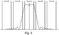
  • Fig. 3 shows a schematic diagram of adjacent slices suffering interference when a target slice, SliceA, is scanned; the solid curve in the figure represents a real echo profile, whereas the dotted curve represents an echo profile obtained by fitting.
  • SliceB, SliceC, SliceD and SliceE all generate an echo, and the strength of the echo signal is gradually attenuated as the distance from SliceA increases; the flip angles of SliceB, SliceC, SliceD and SliceE in the current scanning process can be obtained through measurement of the dotted curve.
  • Step 206 based on the calculated longitudinal magnetization strength after relaxation of each slice when scanning ends, calculating a mean value and a variance of the longitudinal magnetization strengths after relaxation of all slices when scanning ends.
  • Step 207 determining whether all nesting manners have been selected, and if so, performing step 208: otherwise, returning to step 203.
  • Step 208 based on the mean value and variance of the longitudinal magnetization strengths after relaxation of all slices when scanning ends corresponding to each nesting manner, selecting a nesting manner for which the mean value of the longitudinal magnetization strengths is largest and the variance is smallest, and using this nesting manner as an optimal nesting manner.
  • the two nesting manners with the foremost mean values are selected, and the nesting manner with the smaller variance is selected from these two nesting manners as the optimal nesting manner.
  • the optimal nesting manner is used to perform the MRI scan of the tissue.
  • steps 101 - 104 or 201 - 208 described above may be performed once, to find the optimal nesting manner for performing an MRI scan of this type of tissue.
  • nesting manner 1) 1, 2, 3, 4, 5, 6, 7, 8, 9, 10 is used to perform a simulated MRI scan of the tissue, then nesting manner 2) 1, 3, 5, 7, 9, 2, 4, 6, 8, 10 is used to perform a simulated MRI scan of the tissue, and so on, until simulated scans have been completed for all 5 nesting manners.
  • Step 10 using a 180° refocusing pulse to perform a simulated scan of a 10th scan slice, i.e. slice 10.
  • the current simulated scan process ends; the longitudinal magnetization strength after relaxation of each slice under nesting manner 2) is obtained, and the mean value and variance of the longitudinal magnetization strengths after relaxation of all slices corresponding to nesting manner 2) are calculated.
  • FOV field of view
  • TR 4700 ms
  • TE 84 ms
  • the MRI images obtained using a nesting manner with an increment of 4 are optimal.
  • the X arrows in the figures point to the liver; as can be seen, the contrast between the liver and blood vessels is most apparent in figs. c1 - c2; the Y arrows in the figures point to cerebrospinal fluid of the abdomen; as can be seen, the signal strength of cerebrospinal fluid is highest and uniform in figs. c1 - c4, while the signal strength of cerebrospinal fluid is weaker and not uniform in figs. a1 - a4 and figs. d1 - d4.
  • the MRI images obtained using the standard nesting manner i.e. the nesting manner with an increment of 1
  • have poor contrast so this is not the optimal nesting manner.
  • the MRI images obtained using the nesting manner with an increment of 4 have obvious contrast, with the highest signal strength which is also uniform; this is the optimal nesting manner.
  • Fig. 6 is a structural schematic diagram of an apparatus 60, provided in an embodiment of the present invention, for determining an optimal MRI scan nesting manner, the apparatus 60 mainly comprising: a selectable nesting manner determining module 61, a simulated scan module 62 and an optimal nesting manner calculating module 63, wherein:
  • the selectable nesting manner determining module 61 is used for determining all selectable nesting manners according to a preset number of simulated scan slices.
  • the simulated scan module 62 sequentially selects one nesting manner from all the selectable nesting manners determined by the selectable nesting manner determining module 61; and using the selected nesting manner, uses a preset pulse sequence to perform a simulated MRI scan of a set tissue, and calculates a longitudinal magnetization strength after relaxation of each slice when scanning ends.
  • the optimal nesting manner calculating module 63 when all nesting manners have been selected, selects a nesting manner for which the longitudinal magnetization strength after relaxation is smoothest, based on the longitudinal magnetization strength after relaxation of each slice when scanning ends corresponding to each nesting manner as calculated by the simulated scan module 62, and uses this nesting manner as an optimal nesting manner for performing an MRI scan of the tissue.
  • the action of selecting the nesting manner for which the longitudinal magnetization strength after relaxation is smoothest by the optimal nesting manner calculating module 63 comprises: for each nesting manner, calculating a mean value and a variance of the longitudinal magnetization strengths after relaxation of all slices when scanning ends corresponding to the nesting manner; and selecting a nesting manner for which the mean value is largest and the variance is smallest as the nesting manner for which the longitudinal magnetization strength after relaxation is smoothest.
  • the action of calculating the longitudinal magnetization strength after relaxation of each slice when scanning ends by the simulated scan module 62 comprises: when a scan is performed of any target slice, then for the target slice and each slice amongst slices suffering interference, based on a longitudinal magnetization strength after relaxation of the slice in a most recent scanning process and a flip angle of the slice in a current scanning process, calculating a longitudinal magnetization strength after flipping of the slice in the current scanning process, and calculating a longitudinal magnetization strength after relaxation of the slice in the current scanning process on the basis of the longitudinal magnetization strength after flipping of the slice in the current scanning process, wherein for any target slice, an echo profile obtained when a preset pulse is used to perform an MRI scan of the target slice is tested in advance, and slices suffering interference, and the flip angle of each slice suffering interference, are determined on the basis of the echo profile.
  • a preset pulse sequence used by the simulated scan module 62 is TSE.
  • Fig. 7 is a schematic composition diagram of an apparatus 70, provided in another embodiment of the present invention, for determining an optimal MRI scan nesting manner, the apparatus mainly comprising: a processor 71 and a memory 72, wherein: an application program executable by the processor 71 is stored in the memory 72, and used to cause the processor 71 to perform a step of the method for determining an optimal MRI scan nesting manner as described in any one of steps 101 - 104 or 201 - 208.
  • Embodiments of the present invention also provide a readable storage medium, with a computer program stored thereon; when executed by a processor, the computer program realizes a step of the method for determining an optimal MRI scan nesting manner as described in any one of steps 101 - 104 or 201 - 208.
  • a machine-readable instruction is stored on the readable storage medium; the machine-readable instruction, when executed by a processor, causes the processor to perform any one of the methods described above.
  • a system or apparatus equipped with a readable storage medium may be provided; software program code realizing a function of any one of the embodiments above is stored on the readable storage medium, and a computer or processor of the system or apparatus is caused to read and execute a machine-readable instruction stored in the readable storage medium.
  • program code read from the readable storage medium can itself realize a function of any one of the embodiments above, hence machine-readable code and the readable storage medium storing the machine-readable code form part of the present invention.
  • Examples of readable storage media include floppy disks, hard disks, magneto-optical disks, optical disks (such as CD-ROM, CD-R, CD-RW, DVD-ROM, DVD-RAM, DVD-RW, DVD+RW), magnetic tapes, nonvolatile memory cards and ROM.
  • program code may be downloaded from a server computer or a cloud via a communication network.
  • a hardware module may be realized in a mechanical or an electrical manner.
  • a hardware module or processor may comprise a permanent dedicated circuit or logic (e.g. a special processor, FPGA or ASIC) to complete a corresponding operation.
  • a hardware module or processor may also comprise programmable logic or circuitry (e.g. a universal processor or another programmable processor), and may be set temporarily by software to complete a corresponding operation.
  • programmable logic or circuitry e.g. a universal processor or another programmable processor

Landscapes

  • Physics & Mathematics (AREA)
  • Health & Medical Sciences (AREA)
  • High Energy & Nuclear Physics (AREA)
  • Life Sciences & Earth Sciences (AREA)
  • General Physics & Mathematics (AREA)
  • Condensed Matter Physics & Semiconductors (AREA)
  • Nuclear Medicine, Radiotherapy & Molecular Imaging (AREA)
  • Engineering & Computer Science (AREA)
  • General Health & Medical Sciences (AREA)
  • Radiology & Medical Imaging (AREA)
  • Signal Processing (AREA)
  • Biophysics (AREA)
  • Molecular Biology (AREA)
  • Surgery (AREA)
  • Animal Behavior & Ethology (AREA)
  • Medical Informatics (AREA)
  • Public Health (AREA)
  • Veterinary Medicine (AREA)
  • Heart & Thoracic Surgery (AREA)
  • Biomedical Technology (AREA)
  • Pathology (AREA)
  • Optics & Photonics (AREA)
  • Spectroscopy & Molecular Physics (AREA)
  • Magnetic Resonance Imaging Apparatus (AREA)

Abstract

The present invention provides a method and apparatus for determining an optimal MRI scan nesting manner, and a readable storage medium. The method comprises: determining all selectable nesting manners according to a preset number of simulated scan slices; sequentially selecting one nesting manner from all the selectable nesting manners; using the selected nesting manner, using a preset pulse sequence to perform a simulated MRI scan of a set tissue, and calculating a longitudinal magnetization strength after relaxation of each slice when scanning ends; when all nesting manners have been selected, then based on the longitudinal magnetization strength after relaxation of each slice when scanning ends corresponding to each nesting manner, selecting a nesting manner for which the longitudinal magnetization strength after relaxation is smoothest, and using this nesting manner as an optimal nesting manner for performing an MRI scan of the tissue. The present invention can find an optimal MRI scan nesting manner

Description

    Technical field
  • The present invention relates to the technical field of MRI (magnetic resonance imaging), in particular to a method and apparatus for determining an optimal MRI scan nesting manner, and a readable storage medium.
  • Background art
  • In MRI, a radio frequency (RF) pulse of a specific frequency is applied to a human body in a static magnetic field, such that hydrogen protons in the human body are excited and experience the phenomenon of magnetic resonance. When the pulse is stopped, the protons give rise to MR (magnetic resonance) signals in the course of relaxation. An MR image is created by processing such as MR signal reception, spatial encoding and image reconstruction.
  • Commonly used MRI scan pulse sequences are as follows:
    1. 1. SE (Spin-Echo sequence): First of all a 90° excitation pulse is emitted, then a 180° phase refocusing pulse is emitted after an interval of a few milliseconds to a few tens of milliseconds, then an echo signal is measured after a few tens of milliseconds. Thus, there is only one 180° pulse in one TR (repetition time). This is called a spin echo sequence (SE), and is a classic sequence in MR imaging. There are three types of weighted imaging with an SE sequence:
      1. A. PD (proton density) weighted image
        Parameters: long TR = 1500 - 2500 ms, short TE (echo time) = 15 - 30 ms; the amplitude of the echo signal acquired is mainly related to proton density, so this type of image is called a PD weighted image.
      2. B. T2 (transverse relaxation time) weighted image
        Parameters: long TR = 1500 - 2500 ms, long TE = 90 - 120 ms; the amplitude of the echo signal acquired mainly reflects differences in the T2 of tissues, so this type of image is called a T2 weighted image.
      3. C. T1 (longitudinal relaxation time) weighted image
        Parameters: short TR = about 500 ms, short TE = 15 - 30 ms; the amplitude of the echo signal acquired mainly reflects differences in the T1 of tissues, so this type of image is called a T1 weighted image.
    2. 2. TSE (Turbo Spin-Echo sequence): a sequence established on the basis of an SE sequence. First of all a 90° excitation pulse is emitted, then multiple 180° phase refocusing pulses in the same direction are emitted, to form an echo train (ETL, Echo Train Length), thereby shortening the scan time. This is called a turbo spin echo sequence (TSE).
      HASTE (Half-Fourier Acquisition Single-shot Turbo spin-Echo sequence) is one type of TSE sequence, distinctive in being a single-excitation rapid imaging sequence, with a scan time that is reduced by half.
    3. 3. GRE (Gradient-Echo sequence): This is MR imaging using gradient echo. Gradient echo is similar to spin echo. The generation of a spin echo uses a 180° complex phase pulse. With regard to gradient echo generation, forward/reverse switching of the readout gradient field direction is used after one RF excitation to generate a gradient echo.
    4. 4. EPI (Echo Planar Imaging): currently the fastest sequence in MR imaging; the MR signal is also a gradient echo. Unlike ordinary gradient echo, after one RF excitation, successive forward/reverse switching of the readout gradient field is utilized, and one gradient echo is generated each time switching is performed, therefore there is an echo train, similar to TSE. TR is the time needed for a pulse sequence to be executed once. In SE, TR is the time interval between the mid-points of two adjacent 90° pulses; in GRE, TR is the time interval between the mid-points of two adjacent small-angle pulses.
  • Regarding effective TE (Echo Time), in a TSE or EPI sequence, multiple echoes are generated after one 90°pulse excitation, and respectively used to fill different positions of k-space, with each echo having a different TE; in these sequences, the time interval from the mid-point of a 90° pulse to the mid-point of the echo used to fill the centre of k-space is called the effective TE.
  • ETL (Echo Train Length) appears in a TSE or EPI sequence. It is the number of echoes generated or acquired after one 90° pulse excitation.
  • Under the action of an RF pulse, the macroscopic magnetization vector of tissue will deviate from an equilibrium state (i.e. the B0 direction); the angle of deviation thereof is called the flip angle. The flip angle of the macroscopic magnetization vector depends on the energy of the RF pulse; the greater the energy, the greater the flip angle. The energy of the RF pulse depends on the intensity and duration of the pulse, so an increase in energy can be achieved by increasing the intensity or/and duration of the pulse. Flip angles commonly used in MRI are 90°, 180° and small angles commonly used in GRE sequences.
  • A general principle of thermodynamics is that all systems tend towards their own lowest energy states. In the phenomenon of nuclear magnetic resonance, relaxation is a phenomenon whereby, when an atomic nucleus experiences resonance and is in a high-energy state, it will rapidly recover to an original low-energy state after an RF pulse stops. The process of recovery is called the relaxation process, which is an energy conversion process, and the fact that a certain time is needed reflects the interaction between protons in the proton system and between protons and the surrounding environment.
  • The completion of the relaxation process takes place in two steps, i.e. the recovery of the longitudinal magnetization strength vector Mz to M0 of an initial equilibrium state, and the attenuation of the transverse magnetization strength Mxy to zero; these two steps begin at the same time but are completed independently.
  • The T1 relaxation time describes the speed at which the two-energy-level population in the spin system goes to thermal equilibrium from the start.
  • The speed at which the longitudinal magnetization strength component Mz recovers to M0 of the equilibrium state is directly proportional to the extent to which they leave an equilibrium position; when the 90° pulse has acted, an expression for the recovery of the longitudinal magnetization strength Mz can be obtained: Mz t = M 0 1 e t / T 1
    Figure imgb0001
  • T1 in the formula above is the longitudinal relaxation time, abbreviated as T1; generally, the time needed for Mz to recover from zero to 63% of M0 is used to determine T1, i.e. the longitudinal relaxation time T1 is the time needed for Mz to recover to 0.63M0, and t is the length of time from the moment that relaxation began to the current moment.
  • The size of the longitudinal relaxation time T1 depends on the external magnetic field and the interaction between protons and the surrounding environment (i.e. the nature of the tissue). It is an intrinsic characteristic of tissue; for a given external magnetic field, the T1 values of different tissues all have corresponding fixed values, but there is wide variation in the T1 values of different tissues. The external magnetic field B0 (the size of B0) also has an influence on the longitudinal relaxation time T1 of tissue; the longitudinal relaxation time T1 of most tissues decreases as the external magnetic field B0 decreases. However, this is not true in the case of pure water (also called free water); the T1 value thereof does not change as the strength of the external magnetic field changes.
  • The slice thickness in MRI is determined by the slice selection gradient field strength and the RF pulse width; in 2D images, the slice thickness is the thickness of the excited slice. The thinner the slice thickness, the higher the spatial resolution of the image in the slice selection direction, but due to the decrease in voxel volume, the image signal-to-noise ratio is reduced. Thus, when selecting the slice thickness, account must be taken of not only the spatial resolution but also the image signal-to-noise ratio.
  • The distance between two adjacent slices is the slice separation. During MRI imaging, tissue between two slices is not imaged, for example: if the slice thickness is 25 px and the slice separation is 12.5 px, then tissue with a thickness of 12.5 px between two slices is not imaged. MR slice imaging is realized by means of selective RF pulses; due to the influence of gradient field linearity and RF pulse frequency characteristics, etc., protons near a scanned slice will in fact also be excited, and this will result in signals affecting each other between slices; this effect is called inter-slice interference or inter-slice contamination.
  • In order to reduce inter-slice interference, the following two methods are generally used:
    • Method 1: introducing a 10 - 30% slice separation between adjacent slices, so that "tails" of echo signals of adjacent slices do not overlap.
    • Method 2: scanning in a nested manner. That is, when scanning is performed, it is not performed sequentially in the order of slices, but performed in a nested manner. The incremental number of slices in nesting may be one slice or multiple slices. For example, slices are numbered sequentially as slices 1, 2, 3, ..., n according to the positions of the slices in tissue. Then:
  • If scanning is performed in a nested manner with the incremental number of slices being one slice, then the scanned slices are sequentially: slices 1, 2, 3, 4, 5, 6, ...;
  • If scanning is performed in a nested manner with the incremental number of slices being two slices, then the scanned slices are sequentially: slices 1, 3, 5, 7, ..., 2, 4, 6, 8, ...;
  • If scanning is performed in a nested manner with the incremental number of slices being three slices, then the scanned slices are sequentially: slices 1, 4, 7, 10, ..., 2, 5, 8, 11, ..., 3, 6, 9, 12, ...;
  • If scanning is performed in a nested manner with the incremental number of slices being four slices, then the scanned slices are sequentially: slices 1, 5, 9, 13, ..., 2, 6, 10, 14, ..., 3, 7, 11, 15, ..., 4, 8, 12, 16, ...
  • At the present time, when scanning is performed in a nested manner, the incremental number of slices is generally determined based on experience, and as a result, it cannot be ensured that an optimal manner of nesting is used, i.e. that an optimal MRI imaging result is obtained.
  • Content of the invention
  • In order to solve the abovementioned problem, the present invention provides a method for determining an optimal MRI scan nesting manner, in order to find an optimal MRI scan nesting manner;
    the present invention also provides an apparatus for determining an optimal MRI scan nesting manner, in order to find an optimal MRI scan nesting manner;
    the present invention also provides a readable storage medium, in order to find an optimal MRI scan nesting manner.
  • To achieve the abovementioned objective, the present application provides the following technical solution:
    A method for determining an optimal magnetic resonance imaging (MRI) scan nesting manner, comprising:
    • determining all selectable nesting manners according to a preset number of simulated scan slices;
    • sequentially selecting one nesting manner from all the selectable nesting manners;
    • using the selected nesting manner, using a preset pulse sequence to perform a simulated MRI scan of a set tissue, and calculating a longitudinal magnetization strength after relaxation of each slice when scanning ends;
    • when all nesting manners have been selected, then based on the longitudinal magnetization strength after relaxation of each slice when scanning ends corresponding to each nesting manner, selecting a nesting manner for which the longitudinal magnetization strength after relaxation is smoothest, and using this nesting manner as an optimal nesting manner for performing an MRI scan of the tissue.
  • Preferably, the step of determining all the selectable nesting manners comprises:
    • calculating M = └total number of scan slices/2┘, where └┘ is a symbol for rounding down;
    • then there are a total of M selectable nesting manners, wherein the smallest incremental number of slices corresponding to a selectable nesting manner = 1, and the largest incremental number of slices = M.
  • Preferably, the step of selecting the nesting manner for which the longitudinal magnetization strength after relaxation is smoothest comprises:
    • for each nesting manner, calculating a mean value and a variance of the longitudinal magnetization strengths after relaxation of all slices when scanning ends corresponding to the nesting manner;
    • selecting a nesting manner for which the mean value is largest and the variance is smallest as the nesting manner for which the longitudinal magnetization strength after relaxation is smoothest.
  • Preferably, the step of calculating the longitudinal magnetization strength after relaxation of each slice when scanning ends comprises:
    • when a scan is performed of any target slice, then for the target slice and each slice amongst slices suffering interference, based on a longitudinal magnetization strength after relaxation of the slice in a most recent scanning process and a flip angle of the slice in a current scanning process, calculating a longitudinal magnetization strength after flipping of the slice in the current scanning process, and calculating a longitudinal magnetization strength after relaxation of the slice in the current scanning process on the basis of the longitudinal magnetization strength after flipping of the slice in the current scanning process,
    • wherein for any target slice, an echo profile obtained when a preset pulse is used to perform an MRI scan of the target slice is tested in advance, and slices suffering interference, and a flip angle of each slice suffering interference, are determined on the basis of the echo profile.
  • Preferably, the preset pulse sequence is a turbo spin echo (TSE) sequence.
  • An apparatus for determining an optimal magnetic resonance imaging (MRI) scan nesting manner, comprising:
    • a selectable nesting manner determining module, for determining all selectable nesting manners according to a preset number of simulated scan slices;
    • a simulated scan module, which sequentially selects one nesting manner from all the selectable nesting manners determined by the selectable nesting manner determining module; and using the selected nesting manner, uses a preset pulse sequence to perform a simulated MRI scan of a set tissue, and calculates a longitudinal magnetization strength after relaxation of each slice when scanning ends;
    • an optimal nesting manner calculating module which, when all nesting manners have been selected, selects a nesting manner for which the longitudinal magnetization strength after relaxation is smoothest, based on the longitudinal magnetization strength after relaxation of each slice when scanning ends corresponding to each nesting manner as calculated by the simulated scan module, and uses this nesting manner as an optimal nesting manner for performing an MRI scan of the tissue.
  • Preferably, the action of determining all the selectable nesting manners by the selectable nesting manner determining module comprises:
    • calculating M = └total number of scan slices/2┘, where └┘ is a symbol for rounding down;
    • then there are a total of M selectable nesting manners, wherein the smallest incremental number of slices corresponding to a selectable nesting manner = 1, and the largest incremental number of slices = M.
  • Preferably, the action of selecting the nesting manner for which the longitudinal magnetization strength after relaxation is smoothest by the optimal nesting manner calculating module comprises:
    • for each nesting manner, calculating a mean value and a variance of the longitudinal magnetization strengths after relaxation of all slices when scanning ends corresponding to the nesting manner;
    • selecting a nesting manner for which the mean value is largest and the variance is smallest as the nesting manner for which the longitudinal magnetization strength after relaxation is smoothest.
  • Preferably, the action of calculating the longitudinal magnetization strength after relaxation of each slice when scanning ends by the simulated scan module comprises:
    • when a scan is performed of any target slice, then for the target slice and each slice amongst slices suffering interference, based on a longitudinal magnetization strength after relaxation of the slice in a most recent scanning process and a flip angle of the slice in a current scanning process, calculating a longitudinal magnetization strength after flipping of the slice in the current scanning process, and calculating a longitudinal magnetization strength after relaxation of the slice in the current scanning process on the basis of the longitudinal magnetization strength after flipping of the slice in the current scanning process,
    • wherein for any target slice, an echo profile obtained when a preset pulse is used to perform an MRI scan of the target slice is tested in advance, and slices suffering interference, and a flip angle of each slice suffering interference, are determined on the basis of the echo profile.
  • Preferably, the preset pulse sequence used by the simulated scan module is a turbo spin echo (TSE) sequence.
  • A readable storage medium, with a computer program stored thereon; when executed by a processor, the computer program realizes a step of any one of the methods for determining an optimal magnetic resonance imaging (MRI) scan nesting manner as described above.
  • An apparatus for determining an optimal magnetic resonance imaging (MRI) scan nesting manner, the apparatus comprising: a processor and a memory;
    an application program executable by the processor is stored in the memory, and used to cause the processor to perform a step of any one of the methods for determining an optimal magnetic resonance imaging (MRI) scan nesting manner as described above.
  • By using each selectable nesting manner individually to perform a simulated MRI scan of tissue, and selecting the nesting manner for which the longitudinal magnetization strength is smoothest as the optimal nesting manner for performing an MRI scan of the tissue, the present invention finds the optimal MRI scan nesting manner.
  • Description of the accompanying drawings
    • Fig. 1 is a flow chart of a method for determining an optimal MRI scan nesting manner as provided in an embodiment of the present invention.
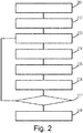
    • Fig. 2 is a flow chart of a method for determining an optimal MRI scan nesting manner as provided in another embodiment of the present invention.
    • Fig. 3 is a schematic diagram of adjacent slices suffering interference when a target slice, SliceA, is scanned.
    • Fig. 4 is a demonstrative diagram of using the method of the present invention to perform an MRI scan of a human brain, and determining an optimal MRI scan nesting manner.
    • Fig. 5 is a demonstrative diagram of using the method of the present invention to perform an MRI scan of a human abdomen, and determining an optimal MRI scan nesting manner.
    • Fig. 6 is a structural schematic diagram of an apparatus for determining an optimal MRI scan nesting manner as provided in an embodiment of the present invention.
    • Fig. 7 is a schematic composition diagram of an apparatus for determining an optimal MRI scan nesting manner as provided in another embodiment of the present invention.
    Key to the drawings:
    Label Meaning
    101 - 104 steps
    201 - 208 steps
    60 apparatus provided in an embodiment of the present invention
    61 selectable nesting manner determining module
    62 simulated scan module
    63 optimal nesting manner calculating module
    70 apparatus provided in another embodiment of the present invention
    71 processor
    72 memory
    Particular embodiments
  • To clarify the objective, technical solution and advantages of the present invention, the technical solution of the present invention is explained in detail below on the basis of embodiments with reference to the accompanying drawings.
  • For example, "a" and "the" in the singular form used in the description of the present invention and the attached claims are also intended to include the plural form, unless clearly specified otherwise herein.
  • The present invention is explained in detail below:
    • Fig. 1 is a flow chart of a method for determining an optimal MRI scan nesting manner as provided in an embodiment of the present invention, the specific steps thereof being as follows:
      • Step 101: determining all selectable MRI scan nesting manners according to a preset number of simulated scan slices.
      • Step 102: sequentially selecting one nesting manner from all the selectable nesting manners.
      • Step 103: using the selected nesting manner, using a preset pulse sequence to perform a simulated MRI scan of a set tissue, and calculating a longitudinal magnetization strength after relaxation of each slice when scanning ends.
      • Step 104: when all nesting manners have been selected, then based on the longitudinal magnetization strength after relaxation when scanning ends corresponding to each nesting manner, selecting a nesting manner for which the longitudinal magnetization strength after relaxation when scanning ends is smoothest, and using this nesting manner as an optimal nesting manner for performing an MRI scan of the tissue.
    • Fig. 2 is a flow chart of a method for determining an optimal MRI scan nesting manner as provided in another embodiment of the present invention, the specific steps thereof being as follows:
      • Step 201: presetting a number n of simulated scan slices.
        This embodiment only simulates an MRI scanning process, and thereby calculates the optimal MRI scan nesting manner; it does not really perform an MRI scanning process.
      • Step 202: determining all selectable MRI scan nesting manners according to the number n of simulated scan slices.
        Each nesting manner corresponds to an incremental number of slices, with the smallest incremental number of slices = 1, and in general, the largest incremental number of slices M = └total number of scan slices/2┘, where └┘ is the symbol for rounding down, so that there are a total of M selectable MRI scan nesting manners.
      • Step 203: sequentially selecting one nesting manner, in order from the smallest to the largest incremental number of slices corresponding to all the selectable MRI scan nesting manners.
      • Step 204: using the selected nesting manner, using TSE to perform a simulated MRI scan of a tissue.
      • Step 205: calculating a longitudinal magnetization strength after relaxation of each slice when scanning ends.
  • When a scan is performed of any target slice, then for the target slice and each slice amongst slices suffering interference, based on a longitudinal magnetization strength after relaxation of the slice in a most recent scanning process and a flip angle of the slice in a current scanning process, a longitudinal magnetization strength after flipping of the slice in the current scanning process is calculated, and a longitudinal magnetization strength after relaxation of the slice in the current scanning process is calculated on the basis of the longitudinal magnetization strength after flipping of the slice in the current scanning process;
    it must be explained that when a 90° excitation pulse or a 180° refocusing pulse is used to scan a target slice, adjacent slices of the target slice will also be scanned, thereby generating an echo signal of a different strength; these adjacent slices are called slices suffering interference, and flip angles of slices suffering interference can be determined by testing in advance. Specifically, for each target slice, an echo profile obtained when a corresponding TSE pulse is used to perform an MRI scan of the target slice is tested in advance, and slices suffering interference, and the flip angle of each slice suffering interference, are determined on the basis of the echo profile.
  • Specifically, for a target slice and each of the slices suffering interference, the longitudinal magnetization strength after relaxation of the slice in the current scanning process is calculated by the following two formulae:
    • Longitudinal magnetization strength after flipping of the slice in the current scanning process = longitudinal magnetization strength after relaxation of the slice in the previous scanning process * cosθ, wherein θ is the flip angle of the slice in the current scanning process;
    • longitudinal magnetization strength after relaxation of the slice in the current scanning process = longitudinal magnetization strength after flipping of the slice in the current scanning process * e-Δt/T1+M0* (1- e-Δt/T1), wherein T1 is the longitudinal relaxation time of the tissue, and Δt is echo spacing, Δt = TR/n/ETL, n being the number of scan slices.
  • Fig. 3 shows a schematic diagram of adjacent slices suffering interference when a target slice, SliceA, is scanned; the solid curve in the figure represents a real echo profile, whereas the dotted curve represents an echo profile obtained by fitting. Clearly, when SliceA is scanned, SliceB, SliceC, SliceD and SliceE all generate an echo, and the strength of the echo signal is gradually attenuated as the distance from SliceA increases; the flip angles of SliceB, SliceC, SliceD and SliceE in the current scanning process can be obtained through measurement of the dotted curve.
  • Step 206: based on the calculated longitudinal magnetization strength after relaxation of each slice when scanning ends, calculating a mean value and a variance of the longitudinal magnetization strengths after relaxation of all slices when scanning ends.
  • Step 207: determining whether all nesting manners have been selected, and if so, performing step 208: otherwise, returning to step 203.
  • Step 208: based on the mean value and variance of the longitudinal magnetization strengths after relaxation of all slices when scanning ends corresponding to each nesting manner, selecting a nesting manner for which the mean value of the longitudinal magnetization strengths is largest and the variance is smallest, and using this nesting manner as an optimal nesting manner.
  • If the longitudinal magnetization strengths after relaxation of all slices when scanning ends corresponding to a nesting manner have the largest mean value but not the smallest variance, then the two nesting manners with the foremost mean values are selected, and the nesting manner with the smaller variance is selected from these two nesting manners as the optimal nesting manner.
  • Subsequently, in an actual application, when performing an MRI scan of this type of tissue, the optimal nesting manner is used to perform the MRI scan of the tissue.
  • In an actual application, for each type of tissue, steps 101 - 104 or 201 - 208 described above may be performed once, to find the optimal nesting manner for performing an MRI scan of this type of tissue.
  • A particular application example is given below:
    An optimal MRI scan nesting manner for a tissue is to be sought. Let the total number of scan slices be n = 10, then the incremental numbers of slices of the selectable nesting manners may be 1, 2, 3, 4 and 5, i.e. the slice scanning orders of the 5 corresponding nesting manners are as follows:
    1. 1) 1, 2, 3, 4, 5, 6, 7, 8, 9, 10;
    2. 2) 1, 3, 5, 7, 9, 2, 4, 6, 8, 10;
    3. 3) 1, 4, 7, 10, 2, 5, 8, 3, 6, 9;
    4. 4) 1, 5, 9, 2, 6, 10, 3, 7, 4, 8;
    5. 5) 1, 6, 2, 7, 3, 8, 4, 9, 5, 10.
  • First of all, nesting manner 1) 1, 2, 3, 4, 5, 6, 7, 8, 9, 10 is used to perform a simulated MRI scan of the tissue, then nesting manner 2) 1, 3, 5, 7, 9, 2, 4, 6, 8, 10 is used to perform a simulated MRI scan of the tissue, and so on, until simulated scans have been completed for all 5 nesting manners.
  • Taking as an example the case where TSE is used and nesting manner 2) 1, 3, 5, 7, 9, 2, 4, 6, 8, 10 is used to perform a simulated MRI scan, the specific process is as follows:
    • Step 01, using a 90° excitation pulse to perform a simulated scan of a 1st scan slice, i.e. slice 1; if it is found, on the basis of an echo profile curve obtained by testing in advance when a 90° excitation pulse is used to scan slice 1, that: when slice 1 is scanned, the flip angles of slices 2 and 3 are θ21 and θ31 respectively, and other slices do not suffer interference, then:
      • longitudinal magnetization strength after first flipping of slice 1 = M0*cos90°;
      • longitudinal magnetization strength after first flipping of slice 2 = M0*cosθ21;
      • longitudinal magnetization strength after first flipping of slice 3 = M0*cosθ31;
      • longitudinal magnetization strength after first relaxation of slice 1 = longitudinal magnetization strength after first flipping of slice 1 * e-Δt/T1+M0* (1- e-Δt/T1) ;
      • longitudinal magnetization strength after first relaxation of slice 2 = longitudinal magnetization strength after first flipping of slice 2 * e-Δt/T1+M0* (1- e-Δt/T1);
      • longitudinal magnetization strength after first relaxation of slice 3 = longitudinal magnetization strength after first flipping of slice 3 * e-Δt/T1+M0* (1- e-Δt/T1);
      • wherein M0 is the value of longitudinal magnetization strength in an equilibrium state, generally let M0 = 1, T1 is the longitudinal relaxation time of the tissue, and Δt is the echo spacing, Δt = TR/n/ETL, n being the number of scan slices.
    • Step 02, using a 180° refocusing pulse to perform a simulated scan of a 2nd scan slice, i.e. slice 3; if it is found, on the basis of an echo profile curve obtained by testing in advance when a 180° refocusing pulse is used to scan slice 3, that: the flip angles of slices 1, 2, 4 and 5 are θ13, θ23, θ43, and θ53 respectively, and other slices do not suffer interference, then:
      • longitudinal magnetization strength after second flipping of slice 3 = longitudinal magnetization strength after first relaxation of slice 3 * cos180°;
      • longitudinal magnetization strength after second flipping of slice 1 = longitudinal magnetization strength after first relaxation of slice 1 * cosθ13;
      • longitudinal magnetization strength after second flipping of slice 2 = longitudinal magnetization strength after first relaxation of slice 2 * cosθ23;
      • longitudinal magnetization strength after first flipping of slice 4 = M0*cosθ43;
      • longitudinal magnetization strength after first flipping of slice 5 = M0*cosθ53;
      • longitudinal magnetization strength after second relaxation of slice 3 = longitudinal magnetization strength after second flipping of slice 3 * e-Δt/T1+M0* (1- e-Δt/T1) ;
      • longitudinal magnetization strength after second relaxation of slice 1 = longitudinal magnetization strength after second flipping of slice 1 * e-Δt/T1+M0* (1- e-Δt/T1);
      • longitudinal magnetization strength after second relaxation of slice 2 = longitudinal magnetization strength after second flipping of slice 2 * e-Δt/T1+M0* (1- e-Δt/T1);
      • longitudinal magnetization strength after first relaxation of slice 4 = longitudinal magnetization strength after first flipping of slice 4 * e-Δt/T1+M0* (1- e-Δt/T1);
      • longitudinal magnetization strength after first relaxation of slice 5 = longitudinal magnetization strength after first flipping of slice 5 * e-Δt/T1+M0* (1- e-Δt/T1).
    • Step 03, using a 180° refocusing pulse to perform a simulated scan of a 3rd scan slice, i.e. slice 5; if it is found, on the basis of an echo profile curve obtained by testing in advance when a 180° refocusing pulse is used to scan slice 5, that: the flip angles of slices 3, 4, 6 and 7 are θ35, θ45, θ65 and θ75 respectively, and other slices do not suffer interference, then:
      • longitudinal magnetization strength after second flipping of slice 5 = longitudinal magnetization strength after first relaxation of slice 5 * cos180° ;
      • longitudinal magnetization strength after third flipping of slice 3 = longitudinal magnetization strength after second relaxation of slice 3 * cosθ35;
      • longitudinal magnetization strength after second flipping of slice 4 = longitudinal magnetization strength after first relaxation of slice 4 * cosθ45;
      • longitudinal magnetization strength after first flipping of slice 6 = M0*cosθ65;
      • longitudinal magnetization strength after first flipping of slice 7 = M0*cosθ75;
      • longitudinal magnetization strength after second relaxation of slice 5 = longitudinal magnetization strength after second flipping of slice 5 * e-Δt/T1+M0* (1- e-Δt/T1);
      • longitudinal magnetization strength after third relaxation of slice 3 = longitudinal magnetization strength after third flipping of slice 3 * e-Δt/T1+M0* (1- e-Δt/T1);
      • longitudinal magnetization strength after second relaxation of slice 4 = longitudinal magnetization strength after second flipping of slice 4 * e-Δt/T1+M0* (1- e-Δt/T1);
      • longitudinal magnetization strength after first relaxation of slice 6 = longitudinal magnetization strength after first flipping of slice 6 * e-Δt/T1+M0* (1- e-Δt/T1);
      • longitudinal magnetization strength after first relaxation of slice 7 = longitudinal magnetization strength after first flipping of slice 7 * e-Δt/T1+M0* (1- e-Δt/T1).
    • Step 04, using a 180° refocusing pulse to perform a simulated scan of a 4th scan slice, i.e. slice 7.
  • The processes of calculating the longitudinal magnetization strength for the flipping and relaxation processes of the target slice and the slices suffering interference are the same as above, so are not described again superfluously.
  • Step 10: using a 180° refocusing pulse to perform a simulated scan of a 10th scan slice, i.e. slice 10.
  • The processes of calculating the longitudinal magnetization strength for the flipping and relaxation processes of the target slice and the slices suffering interference are the same as above, so are not described again superfluously.
  • At this point, the current simulated scan process ends; the longitudinal magnetization strength after relaxation of each slice under nesting manner 2) is obtained, and the mean value and variance of the longitudinal magnetization strengths after relaxation of all slices corresponding to nesting manner 2) are calculated.
  • When simulated scans have been completed for all 5 nesting manners, then based on the mean value and variance of the longitudinal magnetization strengths after relaxation of all layers corresponding to the 5 nesting manners, the nesting manner for which the mean value is largest and the variance is smallest is found therefrom as the optimal nesting manner.
  • Fig. 4 is an example of using the method of the present invention to perform an MRI scan of a human brain, and determining an optimal MRI scan nesting manner, wherein:
    A 1.5T MRI scanner (Siemens Healthineers, Shenzhen, China) and a 16-channel head/neck coil are used to perform T2 brain imaging; the pulse sequence is a TSE sequence, and the protocol parameters are as follows: FOV (field of view) = 208 x 230 mm, TR = 4700 ms, TE = 84 ms, ETL = 21, BW (bandwidth)/pixel = 190 HZ, number of scan slices = 20, distance factor = 30%, voxel = 0.4 x 0.4 x 5 mm, TA (total scan time) = 2:35'.
  • Figs. a1 - a3 are MRI images obtained using a nesting manner with an increment of 1;
    figs. b1 - b3 are MRI images obtained using a nesting manner with an increment of 3;
    figs. c1 - c3 are MRI images obtained using a nesting manner with an increment of 4;
    figs. d1 - d3 are MRI images obtained using a nesting manner with
    an increment of 6.
  • As can be seen, the MRI images obtained using a nesting manner with an increment of 4 are optimal.
  • Fig. 5 is an example of using the method of the present invention to perform an MRI scan of a human abdomen, and determining an optimal MRI scan nesting manner, wherein:
    A 1.5T MRI scanner (Siemens Healthineers, Shenzhen, China) and a 13-channel body matrix coil are used to perform T2 abdomen imaging; the pulse sequence is a haste sequence, (two breath-holds) and the protocol parameters are as follows: FOV = 380 x 309 mm, TE/TR = 91/1000 ms, BW/pixel = 700 Hz, number of scan slices = 30, distance factor = 20%, voxel = 1.5 × 1.5 × 6 mm, TA = 35'.
  • Figs. a1 - a4 are MRI images obtained using a nesting manner with an increment of 1;
    figs. b1 - b4 are MRI images obtained using a nesting manner with an increment of 3;
    figs. c1 - c4 are MRI images obtained using a nesting manner with an increment of 4;
    figs. d1 - d4 are MRI images obtained using a nesting manner with an increment of 6;
    figs. a1, b1, c1 and d1 are MRI images obtained by scanning Slice2; figs. a2, b2, c2 and d2 are MRI images obtained by scanning Slice5; figs. a3, b3, c3 and d3 are MRI images obtained by scanning Slice11; figs. a4, b4, c4 and d4 are MRI images obtained by scanning Slice18.
  • The X arrows in the figures point to the liver; as can be seen, the contrast between the liver and blood vessels is most apparent in figs. c1 - c2;
    the Y arrows in the figures point to cerebrospinal fluid of the abdomen; as can be seen, the signal strength of cerebrospinal fluid is highest and uniform in figs. c1 - c4, while the signal strength of cerebrospinal fluid is weaker and not uniform in figs. a1 - a4 and figs. d1 - d4.
  • It can thus be seen that the MRI images obtained using the standard nesting manner, i.e. the nesting manner with an increment of 1, have poor contrast, so this is not the optimal nesting manner. The MRI images obtained using the nesting manner with an increment of 4 have obvious contrast, with the highest signal strength which is also uniform; this is the optimal nesting manner.
  • Fig. 6 is a structural schematic diagram of an apparatus 60, provided in an embodiment of the present invention, for determining an optimal MRI scan nesting manner, the apparatus 60 mainly comprising: a selectable nesting manner determining module 61, a simulated scan module 62 and an optimal nesting manner calculating module 63, wherein:
    The selectable nesting manner determining module 61 is used for determining all selectable nesting manners according to a preset number of simulated scan slices.
  • The simulated scan module 62 sequentially selects one nesting manner from all the selectable nesting manners determined by the selectable nesting manner determining module 61; and using the selected nesting manner, uses a preset pulse sequence to perform a simulated MRI scan of a set tissue, and calculates a longitudinal magnetization strength after relaxation of each slice when scanning ends.
  • The optimal nesting manner calculating module 63, when all nesting manners have been selected, selects a nesting manner for which the longitudinal magnetization strength after relaxation is smoothest, based on the longitudinal magnetization strength after relaxation of each slice when scanning ends corresponding to each nesting manner as calculated by the simulated scan module 62, and uses this nesting manner as an optimal nesting manner for performing an MRI scan of the tissue.
  • Preferably, the action of determining all selectable nesting manners by the selectable nesting manner determining module 61 comprises:
    calculating M = └total number of scan slices/2┘, where └┘ is the symbol for rounding down; then there are a total of M selectable nesting manners, wherein the smallest incremental number of slices corresponding to a selectable nesting manner = 1, and the largest incremental number of slices = M.
  • Preferably, the action of selecting the nesting manner for which the longitudinal magnetization strength after relaxation is smoothest by the optimal nesting manner calculating module 63 comprises:
    for each nesting manner, calculating a mean value and a variance of the longitudinal magnetization strengths after relaxation of all slices when scanning ends corresponding to the nesting manner; and selecting a nesting manner for which the mean value is largest and the variance is smallest as the nesting manner for which the longitudinal magnetization strength after relaxation is smoothest. Preferably, the action of calculating the longitudinal magnetization strength after relaxation of each slice when scanning ends by the simulated scan module 62 comprises:
    when a scan is performed of any target slice, then for the target slice and each slice amongst slices suffering interference, based on a longitudinal magnetization strength after relaxation of the slice in a most recent scanning process and a flip angle of the slice in a current scanning process, calculating a longitudinal magnetization strength after flipping of the slice in the current scanning process, and calculating a longitudinal magnetization strength after relaxation of the slice in the current scanning process on the basis of the longitudinal magnetization strength after flipping of the slice in the current scanning process, wherein for any target slice, an echo profile obtained when a preset pulse is used to perform an MRI scan of the target slice is tested in advance, and slices suffering interference, and the flip angle of each slice suffering interference, are determined on the basis of the echo profile.
  • Preferably, a preset pulse sequence used by the simulated scan module 62 is TSE.
  • Fig. 7 is a schematic composition diagram of an apparatus 70, provided in another embodiment of the present invention, for determining an optimal MRI scan nesting manner, the apparatus mainly comprising: a processor 71 and a memory 72, wherein:
    an application program executable by the processor 71 is stored in the memory 72, and used to cause the processor 71 to perform a step of the method for determining an optimal MRI scan nesting manner as described in any one of steps 101 - 104 or 201 - 208.
  • Embodiments of the present invention also provide a readable storage medium, with a computer program stored thereon; when executed by a processor, the computer program realizes a step of the method for determining an optimal MRI scan nesting manner as described in any one of steps 101 - 104 or 201 - 208.
  • A machine-readable instruction is stored on the readable storage medium; the machine-readable instruction, when executed by a processor, causes the processor to perform any one of the methods described above. Specifically, a system or apparatus equipped with a readable storage medium may be provided; software program code realizing a function of any one of the embodiments above is stored on the readable storage medium, and a computer or processor of the system or apparatus is caused to read and execute a machine-readable instruction stored in the readable storage medium.
  • In such a situation, program code read from the readable storage medium can itself realize a function of any one of the embodiments above, hence machine-readable code and the readable storage medium storing the machine-readable code form part of the present invention.
  • Examples of readable storage media include floppy disks, hard disks, magneto-optical disks, optical disks (such as CD-ROM, CD-R, CD-RW, DVD-ROM, DVD-RAM, DVD-RW, DVD+RW), magnetic tapes, nonvolatile memory cards and ROM. Optionally, program code may be downloaded from a server computer or a cloud via a communication network.
  • Those skilled in the art should understand that various changes in form and amendments may be made to the embodiments disclosed above without deviating from the substance of the invention. Thus, the scope of protection of the present invention shall be defined by the attached claims.
  • It must be explained that not all of the steps and modules in the flows and system structure diagrams above are necessary; certain steps or modules may be omitted according to actual requirements. The order in which steps are executed is not fixed, but may be adjusted as required. The apparatus structures described in the embodiments above may be physical structures, and may also be logical structures, i.e. some modules might be realized by the same physical entity, or some modules might be realized by multiple physical entities, or realized jointly by certain components in multiple independent devices.
  • In the embodiments above, a hardware module may be realized in a mechanical or an electrical manner. For example, a hardware module or processor may comprise a permanent dedicated circuit or logic (e.g. a special processor, FPGA or ASIC) to complete a corresponding operation. A hardware module or processor may also comprise programmable logic or circuitry (e.g. a universal processor or another programmable processor), and may be set temporarily by software to complete a corresponding operation. Particular embodiments (mechanical, or dedicated permanent circuitry, or temporarily set circuitry) may be determined on the basis of considerations of cost and time.
  • The present invention has been displayed and explained in detail above by means of the accompanying drawings and preferred embodiments, but the present invention is not limited to these disclosed embodiments. Based on the embodiments described above, those skilled in the art will know that further embodiments of the present invention, also falling within the scope of protection of the present invention, could be obtained by combining code checking means in different embodiments above.

Claims (12)

  1. A method for determining an optimal magnetic resonance imaging (MRI) scan nesting manner, characterized by comprising:
    determining all selectable nesting manners according to a preset number of simulated scan slices;
    sequentially selecting one nesting manner from all the selectable nesting manners;
    using the selected nesting manner, using a preset pulse sequence to perform a simulated MRI scan of a set tissue, and calculating a longitudinal magnetization strength after relaxation of each slice when scanning ends;
    when all nesting manners have been selected, then based on the longitudinal magnetization strength after relaxation of each slice when scanning ends corresponding to each nesting manner, selecting a nesting manner for which the longitudinal magnetization strength after relaxation is smoothest, and using this nesting manner as an optimal nesting manner for performing an MRI scan of the tissue.
  2. The method as claimed in claim 1, characterized in that the step of determining all the selectable nesting manners comprises:
    calculating M = └total number of scan slices/2┘, where └┘ is a symbol for rounding down;
    then there are a total of M selectable nesting manners, wherein the smallest incremental number of slices corresponding to a selectable nesting manner = 1, and the largest incremental number of slices = M.
  3. The method as claimed in claim 1, characterized in that the step of selecting the nesting manner for which the longitudinal magnetization strength after relaxation is smoothest comprises:
    for each nesting manner, calculating a mean value and a variance of the longitudinal magnetization strengths after relaxation of all slices when scanning ends corresponding to the nesting manner;
    selecting a nesting manner for which the mean value is largest and the variance is smallest as the nesting manner for which the longitudinal magnetization strength after relaxation is smoothest.
  4. The method as claimed in claim 1, characterized in that the step of calculating the longitudinal magnetization strength after relaxation of each slice when scanning ends comprises:
    when a scan is performed of any target slice, then for the target slice and each slice amongst slices suffering interference, based on a longitudinal magnetization strength after relaxation of the slice in a most recent scanning process and a flip angle of the slice in a current scanning process, calculating a longitudinal magnetization strength after flipping of the slice in the current scanning process, and calculating a longitudinal magnetization strength after relaxation of the slice in the current scanning process on the basis of the longitudinal magnetization strength after flipping of the slice in the current scanning process,
    wherein for any target slice, an echo profile obtained when a preset pulse is used to perform an MRI scan of the target slice is tested in advance, and slices suffering interference, and a flip angle of each slice suffering interference, are determined on the basis of the echo profile.
  5. The method as claimed in claim 1, characterized in that the preset pulse sequence is a turbo spin echo (TSE) sequence.
  6. An apparatus (60) for determining an optimal magnetic resonance imaging (MRI) scan nesting manner, characterized by comprising:
    a selectable nesting manner determining module (61), for determining all selectable nesting manners according to a preset number of simulated scan slices;
    a simulated scan module (62), which sequentially selects one nesting manner from all the selectable nesting manners determined by the selectable nesting manner determining module (61); and using the selected nesting manner, uses a preset pulse sequence to perform a simulated MRI scan of a set tissue, and calculates a longitudinal magnetization strength after relaxation of each slice when scanning ends;
    an optimal nesting manner calculating module (63) which, when all nesting manners have been selected, selects a nesting manner for which the longitudinal magnetization strength after relaxation is smoothest, based on the longitudinal magnetization strength after relaxation of each slice when scanning ends corresponding to each nesting manner as calculated by the simulated scan module (62), and uses this nesting manner as an optimal nesting manner for performing an MRI scan of the tissue.
  7. The apparatus (60) as claimed in claim 6, characterized in that the action of determining all the selectable nesting manners by the selectable nesting manner determining module (61) comprises:
    calculating M = └total number of scan slices/2┘, where └┘ is a symbol for rounding down;
    then there are a total of M selectable nesting manners, wherein the smallest incremental number of slices corresponding to a selectable nesting manner = 1, and the largest incremental number of slices = M.
  8. The apparatus (60) as claimed in claim 6, characterized in that the action of selecting the nesting manner for which the longitudinal magnetization strength after relaxation is smoothest by the optimal nesting manner calculating module (63) comprises:
    for each nesting manner, calculating a mean value and a variance of the longitudinal magnetization strengths after relaxation of all slices when scanning ends corresponding to the nesting manner;
    selecting a nesting manner for which the mean value is largest and the variance is smallest as the nesting manner for which the longitudinal magnetization strength after relaxation is smoothest.
  9. The apparatus (60) as claimed in claim 6, characterized in that the action of calculating the longitudinal magnetization strength after relaxation of each slice when scanning ends by the simulated scan module (62) comprises:
    when a scan is performed of any target slice, then for the target slice and each slice amongst slices suffering interference, based on a longitudinal magnetization strength after relaxation of the slice in a most recent scanning process and a flip angle of the slice in a current scanning process, calculating a longitudinal magnetization strength after flipping of the slice in the current scanning process, and calculating a longitudinal magnetization strength after relaxation of the slice in the current scanning process on the basis of the longitudinal magnetization strength after flipping of the slice in the current scanning process,
    wherein for any target slice, an echo profile obtained when a preset pulse is used to perform an MRI scan of the target slice is tested in advance, and slices suffering interference, and a flip angle of each slice suffering interference, are determined on the basis of the echo profile.
  10. The apparatus (60) as claimed in claim 6, characterized in that the preset pulse sequence used by the simulated scan module (62) is a turbo spin echo (TSE) sequence.
  11. A readable storage medium, with a computer program stored thereon, characterized in that when executed by a processor, the computer program realizes a step of the method for determining an optimal magnetic resonance imaging (MRI) scan nesting manner as claimed in any one of claims 1 - 5.
  12. An apparatus (70) for determining an optimal magnetic resonance imaging (MRI) scan nesting manner, characterized in that the apparatus comprises: a processor (71) and a memory (72); an application program executable by the processor (71) is tored in the memory (72), and used to cause the processor (71) to perform a step of the method for determining an optimal magnetic resonance imaging (MRI) scan nesting manner as claimed in any one of claims 1 - 5.
EP19194033.7A 2018-08-29 2019-08-28 Method and apparatus for determining an optimal slice acquisition order for magnetic resonance imaging Pending EP3617732A1 (en)

Applications Claiming Priority (1)

Application Number Priority Date Filing Date Title
CN201810992601.3A CN110873856B (en) 2018-08-29 2018-08-29 Method and device for determining optimal magnetic resonance imaging scanning nesting mode

Publications (1)

Publication Number Publication Date
EP3617732A1 true EP3617732A1 (en) 2020-03-04

Family

ID=67777164

Family Applications (1)

Application Number Title Priority Date Filing Date
EP19194033.7A Pending EP3617732A1 (en) 2018-08-29 2019-08-28 Method and apparatus for determining an optimal slice acquisition order for magnetic resonance imaging

Country Status (3)

Country Link
US (1) US11294010B2 (en)
EP (1) EP3617732A1 (en)
CN (1) CN110873856B (en)

Families Citing this family (2)

* Cited by examiner, † Cited by third party
Publication number Priority date Publication date Assignee Title
US20230197245A1 (en) * 2020-06-10 2023-06-22 Corsmed Ab A method directed to magnetic resonance (mr) imaging simulation
CN113805129B (en) * 2020-06-11 2024-01-02 西门子(深圳)磁共振有限公司 Data acquisition device, method and magnetic resonance imaging device

Citations (2)

* Cited by examiner, † Cited by third party
Publication number Priority date Publication date Assignee Title
EP0284284A2 (en) * 1987-03-23 1988-09-28 Varian Associates, Inc. Method and apparatus for execution of multislice imaging experiments
US20160178719A1 (en) * 2014-12-18 2016-06-23 Siemens Healthcare Gmbh Multi-slice magnetic resonance data acquisition method and imaging apparatus

Family Cites Families (15)

* Cited by examiner, † Cited by third party
Publication number Priority date Publication date Assignee Title
US4673880A (en) 1985-08-16 1987-06-16 Technicare Corporation Phase sensitive detection in multislice magnetic resonance imaging systems
US5406203A (en) * 1992-08-10 1995-04-11 The Trustees Of Columbia University In The City Of New York Methods of multislice acquisition for magnetic resonance imaging
JP3348572B2 (en) 1995-08-21 2002-11-20 株式会社島津製作所 MR imaging device
WO2008135888A1 (en) * 2007-05-04 2008-11-13 Koninklijke Philips Electronics N.V. Method and multi-channel rf transmitter arrangement for generating rf fields
CN102772206B (en) * 2011-05-12 2014-11-19 上海联影医疗科技有限公司 Magnetic resonance imaging method
US8803523B2 (en) * 2012-02-03 2014-08-12 The Board Of Trustees Of The Leland Stanford Junior University Flexible ordering for multiple slice MRI
US9322896B2 (en) * 2012-04-20 2016-04-26 University Of Virginia Patent Foundation Systems and methods for reduced off-resonance blurring in spiral imaging
CN103239230B (en) * 2013-05-08 2015-04-01 深圳安科高技术股份有限公司 Method and system for automatically testing magnetic resonance scanning schemes
US10061007B2 (en) * 2014-06-27 2018-08-28 General Electric Company Method, apparatus, and article for frequency-overlapped 3-D multispectral magnetic resonance images
CN104224179A (en) * 2014-09-10 2014-12-24 中国科学院电工研究所 Magnetic field stabilizing method and device for magnetic resonance imaging system
JP2016189979A (en) * 2015-03-31 2016-11-10 東芝メディカルシステムズ株式会社 Magnetic-resonance imaging apparatus
RU2613083C1 (en) * 2015-12-28 2017-03-15 Федеральное государственное бюджетное образовательное учреждение высшего образования "Российский национальный исследовательский медицинский университет имени Н.И. Пирогова" Министерства здравоохранения Российской Федерации (ФГБОУ ВО РНИМУ им. Н.И. Пирогова Минздрава России) Method for determining volume of tumour in case of cervical cancer in performing magnetic-resonance tomography
CN106198597B (en) * 2016-07-04 2018-11-09 中国科学院自动化研究所 Calculating neurotomy processing method based on histology and super high field mr techniques
CN107271937B (en) * 2017-07-04 2019-07-23 南京拓谱医疗科技有限公司 A kind of synchronous acquisition and calibration method of three-dimensional multi-parameter weighted magnetic resonance imaging
CN108209918B (en) * 2017-12-30 2021-09-07 上海联影医疗科技股份有限公司 Magnetic resonance imaging method and magnetic resonance system

Patent Citations (2)

* Cited by examiner, † Cited by third party
Publication number Priority date Publication date Assignee Title
EP0284284A2 (en) * 1987-03-23 1988-09-28 Varian Associates, Inc. Method and apparatus for execution of multislice imaging experiments
US20160178719A1 (en) * 2014-12-18 2016-06-23 Siemens Healthcare Gmbh Multi-slice magnetic resonance data acquisition method and imaging apparatus

Non-Patent Citations (2)

* Cited by examiner, † Cited by third party
Title
"Handbook of MRI Pulse Sequences", 1 January 2004, ELSEVIER ACADEMIC PRESS, Amsterdam, article MATT A. BRENSTEIN ET AL: "Cross-Talk and Slice Ordering", pages: 410 - 415, XP055614600 *
TAKASHI SAKAI ET AL: "Simulation Analysis of Multislice Profiles in MRI Based on Bloch Equation", MEDICAL IMAGING AND INFORMATION SCIENCES, vol. 23, no. 3, 1 January 2006 (2006-01-01), pages 100 - 104, XP055656269, ISSN: 0910-1543 *

Also Published As

Publication number Publication date
CN110873856A (en) 2020-03-10
US20200072930A1 (en) 2020-03-05
US11294010B2 (en) 2022-04-05
CN110873856B (en) 2022-08-09

Similar Documents

Publication Publication Date Title
EP2414861B1 (en) Magnetic resonance imaging with improved imaging contrast
KR101625557B1 (en) Method and control device to operate a magnetic resonance system
JP6081273B2 (en) Slice-specific phase correction in slice multiplexing
EP0529527B1 (en) Method and apparatus for high speed magnetic resonance imaging with improved image quality
US8228063B2 (en) Magnetic resonance imaging apparatus and magnetic resonance imaging method
US6400151B1 (en) Method and apparatus for the acquisition of data for magnetic resonance imaging
US9041394B2 (en) Magnetic resonance imaging apparatus executing phase-corrected imaging pulse sequence based on data obtained from multiple pulse sub-sequences executed without readout direction gradients but instead using phase or slice encoding direction gradients during readout
CN102772210B (en) Diffusion weighted MR imaging
US10620280B2 (en) System and method for magnetic resonance image acquisition
GB2320576A (en) A multi-echo Dixon water and fat separation sequence
CN109814058A (en) CAIPIRINHA WAVE SPACE
CN105473067A (en) System and method for reducing acoustic noise level in MR imaging
JP6762284B2 (en) Magnetic resonance imaging device and noise removal method
Chen et al. Self‐calibrating wave‐encoded variable‐density single‐shot fast spin echo imaging
US20200103484A1 (en) Correction method and system for slice multiplexing echo planar imaging methods
US5079505A (en) Method in the form of a pulse sequence for fast calculation of images of the fat and water distribution in an examination subject on the basis of nuclear magnetic resonance
EP3617732A1 (en) Method and apparatus for determining an optimal slice acquisition order for magnetic resonance imaging
EP3667353B1 (en) Improved image quality in spin echo based imaging with parallel mri
JPH08266515A (en) Nuclear spin tomography device
Jhooti et al. A fully automatic and highly efficient navigator gating technique for high‐resolution free‐breathing acquisitions: continuously adaptive windowing strategy
KR20180007327A (en) Reducing artifacts in magnetic resonance technology
JP6172730B2 (en) MRI equipment
KR102604679B1 (en) Single-shot Pseudo-centric EPI for Magnetization-Prepared Imaging method
CN113808228B (en) Imaging echo phase correction method, device, imaging system and storage medium
JP2011206493A (en) Magnetic resonance imaging apparatus

Legal Events

Date Code Title Description
PUAI Public reference made under article 153(3) epc to a published international application that has entered the european phase

Free format text: ORIGINAL CODE: 0009012

STAA Information on the status of an ep patent application or granted ep patent

Free format text: STATUS: REQUEST FOR EXAMINATION WAS MADE

17P Request for examination filed

Effective date: 20190828

AK Designated contracting states

Kind code of ref document: A1

Designated state(s): AL AT BE BG CH CY CZ DE DK EE ES FI FR GB GR HR HU IE IS IT LI LT LU LV MC MK MT NL NO PL PT RO RS SE SI SK SM TR

AX Request for extension of the european patent

Extension state: BA ME

RBV Designated contracting states (corrected)

Designated state(s): AL AT BE BG CH CY CZ DE DK EE ES FI FR GB GR HR HU IE IS IT LI LT LU LV MC MK MT NL NO PL PT RO RS SE SI SK SM TR

STAA Information on the status of an ep patent application or granted ep patent

Free format text: STATUS: EXAMINATION IS IN PROGRESS

17Q First examination report despatched

Effective date: 20220601

RAP1 Party data changed (applicant data changed or rights of an application transferred)

Owner name: SIEMENS HEALTHINEERS AG