EP3617666A2 - Fluidstandsensorvorrichtung mit ineinandergreifenden planaren kondensatoren zum direkten einsetzen in ein fluid - Google Patents
Fluidstandsensorvorrichtung mit ineinandergreifenden planaren kondensatoren zum direkten einsetzen in ein fluid Download PDFInfo
- Publication number
- EP3617666A2 EP3617666A2 EP19176251.7A EP19176251A EP3617666A2 EP 3617666 A2 EP3617666 A2 EP 3617666A2 EP 19176251 A EP19176251 A EP 19176251A EP 3617666 A2 EP3617666 A2 EP 3617666A2
- Authority
- EP
- European Patent Office
- Prior art keywords
- fluid
- metallic shield
- digitated
- inter
- sense element
- Prior art date
- Legal status (The legal status is an assumption and is not a legal conclusion. Google has not performed a legal analysis and makes no representation as to the accuracy of the status listed.)
- Withdrawn
Links
- 239000012530 fluid Substances 0.000 title claims abstract description 199
- 239000003990 capacitor Substances 0.000 title claims abstract description 147
- 239000011521 glass Substances 0.000 claims abstract description 22
- 238000002161 passivation Methods 0.000 claims abstract description 22
- 239000011248 coating agent Substances 0.000 claims abstract description 17
- 238000000576 coating method Methods 0.000 claims abstract description 17
- 239000000758 substrate Substances 0.000 claims abstract description 15
- 230000004888 barrier function Effects 0.000 claims abstract description 5
- 238000009423 ventilation Methods 0.000 claims description 6
- 150000004756 silanes Chemical class 0.000 claims description 5
- 238000005259 measurement Methods 0.000 description 51
- 239000003921 oil Substances 0.000 description 34
- 239000010410 layer Substances 0.000 description 23
- 238000000034 method Methods 0.000 description 14
- 230000008859 change Effects 0.000 description 13
- 230000007613 environmental effect Effects 0.000 description 10
- 239000000463 material Substances 0.000 description 6
- 238000004382 potting Methods 0.000 description 6
- 239000000843 powder Substances 0.000 description 6
- 230000008901 benefit Effects 0.000 description 5
- 239000002904 solvent Substances 0.000 description 5
- 238000005516 engineering process Methods 0.000 description 4
- -1 for example Substances 0.000 description 4
- 239000007788 liquid Substances 0.000 description 4
- 230000013011 mating Effects 0.000 description 4
- 239000010705 motor oil Substances 0.000 description 4
- 239000004033 plastic Substances 0.000 description 4
- 229920001343 polytetrafluoroethylene Polymers 0.000 description 4
- 239000004810 polytetrafluoroethylene Substances 0.000 description 4
- 239000000725 suspension Substances 0.000 description 4
- 230000000694 effects Effects 0.000 description 3
- 238000001914 filtration Methods 0.000 description 3
- 239000007789 gas Substances 0.000 description 3
- 125000002887 hydroxy group Chemical group [H]O* 0.000 description 3
- 238000012886 linear function Methods 0.000 description 3
- 230000008569 process Effects 0.000 description 3
- 230000004044 response Effects 0.000 description 3
- 239000000565 sealant Substances 0.000 description 3
- 239000000126 substance Substances 0.000 description 3
- XLYOFNOQVPJJNP-UHFFFAOYSA-N water Substances O XLYOFNOQVPJJNP-UHFFFAOYSA-N 0.000 description 3
- BLRPTPMANUNPDV-UHFFFAOYSA-N Silane Chemical compound [SiH4] BLRPTPMANUNPDV-UHFFFAOYSA-N 0.000 description 2
- 150000001343 alkyl silanes Chemical class 0.000 description 2
- 229910052782 aluminium Inorganic materials 0.000 description 2
- XAGFODPZIPBFFR-UHFFFAOYSA-N aluminium Chemical compound [Al] XAGFODPZIPBFFR-UHFFFAOYSA-N 0.000 description 2
- 239000004020 conductor Substances 0.000 description 2
- 230000001419 dependent effect Effects 0.000 description 2
- 230000003993 interaction Effects 0.000 description 2
- 238000002955 isolation Methods 0.000 description 2
- 229910000077 silane Inorganic materials 0.000 description 2
- ZOXJGFHDIHLPTG-UHFFFAOYSA-N Boron Chemical compound [B] ZOXJGFHDIHLPTG-UHFFFAOYSA-N 0.000 description 1
- 239000004215 Carbon black (E152) Substances 0.000 description 1
- RYGMFSIKBFXOCR-UHFFFAOYSA-N Copper Chemical compound [Cu] RYGMFSIKBFXOCR-UHFFFAOYSA-N 0.000 description 1
- 239000000020 Nitrocellulose Substances 0.000 description 1
- NRTOMJZYCJJWKI-UHFFFAOYSA-N Titanium nitride Chemical compound [Ti]#N NRTOMJZYCJJWKI-UHFFFAOYSA-N 0.000 description 1
- HCHKCACWOHOZIP-UHFFFAOYSA-N Zinc Chemical compound [Zn] HCHKCACWOHOZIP-UHFFFAOYSA-N 0.000 description 1
- 239000004110 Zinc silicate Substances 0.000 description 1
- FJWGYAHXMCUOOM-QHOUIDNNSA-N [(2s,3r,4s,5r,6r)-2-[(2r,3r,4s,5r,6s)-4,5-dinitrooxy-2-(nitrooxymethyl)-6-[(2r,3r,4s,5r,6s)-4,5,6-trinitrooxy-2-(nitrooxymethyl)oxan-3-yl]oxyoxan-3-yl]oxy-3,5-dinitrooxy-6-(nitrooxymethyl)oxan-4-yl] nitrate Chemical compound O([C@@H]1O[C@@H]([C@H]([C@H](O[N+]([O-])=O)[C@H]1O[N+]([O-])=O)O[C@H]1[C@@H]([C@@H](O[N+]([O-])=O)[C@H](O[N+]([O-])=O)[C@@H](CO[N+]([O-])=O)O1)O[N+]([O-])=O)CO[N+](=O)[O-])[C@@H]1[C@@H](CO[N+]([O-])=O)O[C@@H](O[N+]([O-])=O)[C@H](O[N+]([O-])=O)[C@H]1O[N+]([O-])=O FJWGYAHXMCUOOM-QHOUIDNNSA-N 0.000 description 1
- IVGZFMVIHQRCHJ-UHFFFAOYSA-N [Zn].[Bi].[B] Chemical compound [Zn].[Bi].[B] IVGZFMVIHQRCHJ-UHFFFAOYSA-N 0.000 description 1
- 230000032683 aging Effects 0.000 description 1
- 238000004873 anchoring Methods 0.000 description 1
- 239000011230 binding agent Substances 0.000 description 1
- 230000015572 biosynthetic process Effects 0.000 description 1
- 229910052797 bismuth Inorganic materials 0.000 description 1
- JCXGWMGPZLAOME-UHFFFAOYSA-N bismuth atom Chemical compound [Bi] JCXGWMGPZLAOME-UHFFFAOYSA-N 0.000 description 1
- 229910000416 bismuth oxide Inorganic materials 0.000 description 1
- 229910052796 boron Inorganic materials 0.000 description 1
- 239000013590 bulk material Substances 0.000 description 1
- 239000000919 ceramic Substances 0.000 description 1
- 210000001520 comb Anatomy 0.000 description 1
- 229910052802 copper Inorganic materials 0.000 description 1
- 239000010949 copper Substances 0.000 description 1
- 238000000151 deposition Methods 0.000 description 1
- TYIXMATWDRGMPF-UHFFFAOYSA-N dibismuth;oxygen(2-) Chemical compound [O-2].[O-2].[O-2].[Bi+3].[Bi+3] TYIXMATWDRGMPF-UHFFFAOYSA-N 0.000 description 1
- 239000003989 dielectric material Substances 0.000 description 1
- 230000005684 electric field Effects 0.000 description 1
- 230000005672 electromagnetic field Effects 0.000 description 1
- 238000009713 electroplating Methods 0.000 description 1
- 150000002148 esters Chemical class 0.000 description 1
- NBVXSUQYWXRMNV-UHFFFAOYSA-N fluoromethane Chemical compound FC NBVXSUQYWXRMNV-UHFFFAOYSA-N 0.000 description 1
- 229920002313 fluoropolymer Polymers 0.000 description 1
- 239000002241 glass-ceramic Substances 0.000 description 1
- PCHJSUWPFVWCPO-UHFFFAOYSA-N gold Chemical compound [Au] PCHJSUWPFVWCPO-UHFFFAOYSA-N 0.000 description 1
- 229910052737 gold Inorganic materials 0.000 description 1
- 239000010931 gold Substances 0.000 description 1
- 229930195733 hydrocarbon Natural products 0.000 description 1
- 150000002430 hydrocarbons Chemical class 0.000 description 1
- 239000001257 hydrogen Substances 0.000 description 1
- 229910052739 hydrogen Inorganic materials 0.000 description 1
- 230000002209 hydrophobic effect Effects 0.000 description 1
- 229910000464 lead oxide Inorganic materials 0.000 description 1
- 238000002844 melting Methods 0.000 description 1
- 230000008018 melting Effects 0.000 description 1
- 239000000203 mixture Substances 0.000 description 1
- 238000012986 modification Methods 0.000 description 1
- 230000004048 modification Effects 0.000 description 1
- 229920001220 nitrocellulos Polymers 0.000 description 1
- ORQBXQOJMQIAOY-UHFFFAOYSA-N nobelium Chemical compound [No] ORQBXQOJMQIAOY-UHFFFAOYSA-N 0.000 description 1
- YEXPOXQUZXUXJW-UHFFFAOYSA-N oxolead Chemical compound [Pb]=O YEXPOXQUZXUXJW-UHFFFAOYSA-N 0.000 description 1
- 230000000704 physical effect Effects 0.000 description 1
- 229910021420 polycrystalline silicon Inorganic materials 0.000 description 1
- 229920000642 polymer Polymers 0.000 description 1
- 229920000193 polymethacrylate Polymers 0.000 description 1
- 229920005591 polysilicon Polymers 0.000 description 1
- 238000007639 printing Methods 0.000 description 1
- 238000007650 screen-printing Methods 0.000 description 1
- 230000035945 sensitivity Effects 0.000 description 1
- 239000005368 silicate glass Substances 0.000 description 1
- 239000002356 single layer Substances 0.000 description 1
- 239000007787 solid Substances 0.000 description 1
- 238000006467 substitution reaction Methods 0.000 description 1
- 238000004381 surface treatment Methods 0.000 description 1
- 239000013598 vector Substances 0.000 description 1
- 229910052725 zinc Inorganic materials 0.000 description 1
- 239000011701 zinc Substances 0.000 description 1
Images





Classifications
-
- G—PHYSICS
- G01—MEASURING; TESTING
- G01F—MEASURING VOLUME, VOLUME FLOW, MASS FLOW OR LIQUID LEVEL; METERING BY VOLUME
- G01F23/00—Indicating or measuring liquid level or level of fluent solid material, e.g. indicating in terms of volume or indicating by means of an alarm
- G01F23/22—Indicating or measuring liquid level or level of fluent solid material, e.g. indicating in terms of volume or indicating by means of an alarm by measuring physical variables, other than linear dimensions, pressure or weight, dependent on the level to be measured, e.g. by difference of heat transfer of steam or water
- G01F23/26—Indicating or measuring liquid level or level of fluent solid material, e.g. indicating in terms of volume or indicating by means of an alarm by measuring physical variables, other than linear dimensions, pressure or weight, dependent on the level to be measured, e.g. by difference of heat transfer of steam or water by measuring variations of capacity or inductance of capacitors or inductors arising from the presence of liquid or fluent solid material in the electric or electromagnetic fields
- G01F23/263—Indicating or measuring liquid level or level of fluent solid material, e.g. indicating in terms of volume or indicating by means of an alarm by measuring physical variables, other than linear dimensions, pressure or weight, dependent on the level to be measured, e.g. by difference of heat transfer of steam or water by measuring variations of capacity or inductance of capacitors or inductors arising from the presence of liquid or fluent solid material in the electric or electromagnetic fields by measuring variations in capacitance of capacitors
-
- G—PHYSICS
- G01—MEASURING; TESTING
- G01F—MEASURING VOLUME, VOLUME FLOW, MASS FLOW OR LIQUID LEVEL; METERING BY VOLUME
- G01F23/00—Indicating or measuring liquid level or level of fluent solid material, e.g. indicating in terms of volume or indicating by means of an alarm
- G01F23/22—Indicating or measuring liquid level or level of fluent solid material, e.g. indicating in terms of volume or indicating by means of an alarm by measuring physical variables, other than linear dimensions, pressure or weight, dependent on the level to be measured, e.g. by difference of heat transfer of steam or water
- G01F23/26—Indicating or measuring liquid level or level of fluent solid material, e.g. indicating in terms of volume or indicating by means of an alarm by measuring physical variables, other than linear dimensions, pressure or weight, dependent on the level to be measured, e.g. by difference of heat transfer of steam or water by measuring variations of capacity or inductance of capacitors or inductors arising from the presence of liquid or fluent solid material in the electric or electromagnetic fields
- G01F23/263—Indicating or measuring liquid level or level of fluent solid material, e.g. indicating in terms of volume or indicating by means of an alarm by measuring physical variables, other than linear dimensions, pressure or weight, dependent on the level to be measured, e.g. by difference of heat transfer of steam or water by measuring variations of capacity or inductance of capacitors or inductors arising from the presence of liquid or fluent solid material in the electric or electromagnetic fields by measuring variations in capacitance of capacitors
- G01F23/265—Indicating or measuring liquid level or level of fluent solid material, e.g. indicating in terms of volume or indicating by means of an alarm by measuring physical variables, other than linear dimensions, pressure or weight, dependent on the level to be measured, e.g. by difference of heat transfer of steam or water by measuring variations of capacity or inductance of capacitors or inductors arising from the presence of liquid or fluent solid material in the electric or electromagnetic fields by measuring variations in capacitance of capacitors for discrete levels
-
- G—PHYSICS
- G01—MEASURING; TESTING
- G01F—MEASURING VOLUME, VOLUME FLOW, MASS FLOW OR LIQUID LEVEL; METERING BY VOLUME
- G01F23/00—Indicating or measuring liquid level or level of fluent solid material, e.g. indicating in terms of volume or indicating by means of an alarm
- G01F23/22—Indicating or measuring liquid level or level of fluent solid material, e.g. indicating in terms of volume or indicating by means of an alarm by measuring physical variables, other than linear dimensions, pressure or weight, dependent on the level to be measured, e.g. by difference of heat transfer of steam or water
- G01F23/26—Indicating or measuring liquid level or level of fluent solid material, e.g. indicating in terms of volume or indicating by means of an alarm by measuring physical variables, other than linear dimensions, pressure or weight, dependent on the level to be measured, e.g. by difference of heat transfer of steam or water by measuring variations of capacity or inductance of capacitors or inductors arising from the presence of liquid or fluent solid material in the electric or electromagnetic fields
- G01F23/263—Indicating or measuring liquid level or level of fluent solid material, e.g. indicating in terms of volume or indicating by means of an alarm by measuring physical variables, other than linear dimensions, pressure or weight, dependent on the level to be measured, e.g. by difference of heat transfer of steam or water by measuring variations of capacity or inductance of capacitors or inductors arising from the presence of liquid or fluent solid material in the electric or electromagnetic fields by measuring variations in capacitance of capacitors
- G01F23/268—Indicating or measuring liquid level or level of fluent solid material, e.g. indicating in terms of volume or indicating by means of an alarm by measuring physical variables, other than linear dimensions, pressure or weight, dependent on the level to be measured, e.g. by difference of heat transfer of steam or water by measuring variations of capacity or inductance of capacitors or inductors arising from the presence of liquid or fluent solid material in the electric or electromagnetic fields by measuring variations in capacitance of capacitors mounting arrangements of probes
-
- F—MECHANICAL ENGINEERING; LIGHTING; HEATING; WEAPONS; BLASTING
- F01—MACHINES OR ENGINES IN GENERAL; ENGINE PLANTS IN GENERAL; STEAM ENGINES
- F01M—LUBRICATING OF MACHINES OR ENGINES IN GENERAL; LUBRICATING INTERNAL COMBUSTION ENGINES; CRANKCASE VENTILATING
- F01M11/00—Component parts, details or accessories, not provided for in, or of interest apart from, groups F01M1/00 - F01M9/00
- F01M11/10—Indicating devices; Other safety devices
- F01M11/12—Indicating devices; Other safety devices concerning lubricant level
-
- G—PHYSICS
- G01—MEASURING; TESTING
- G01F—MEASURING VOLUME, VOLUME FLOW, MASS FLOW OR LIQUID LEVEL; METERING BY VOLUME
- G01F23/00—Indicating or measuring liquid level or level of fluent solid material, e.g. indicating in terms of volume or indicating by means of an alarm
- G01F23/22—Indicating or measuring liquid level or level of fluent solid material, e.g. indicating in terms of volume or indicating by means of an alarm by measuring physical variables, other than linear dimensions, pressure or weight, dependent on the level to be measured, e.g. by difference of heat transfer of steam or water
- G01F23/26—Indicating or measuring liquid level or level of fluent solid material, e.g. indicating in terms of volume or indicating by means of an alarm by measuring physical variables, other than linear dimensions, pressure or weight, dependent on the level to be measured, e.g. by difference of heat transfer of steam or water by measuring variations of capacity or inductance of capacitors or inductors arising from the presence of liquid or fluent solid material in the electric or electromagnetic fields
- G01F23/263—Indicating or measuring liquid level or level of fluent solid material, e.g. indicating in terms of volume or indicating by means of an alarm by measuring physical variables, other than linear dimensions, pressure or weight, dependent on the level to be measured, e.g. by difference of heat transfer of steam or water by measuring variations of capacity or inductance of capacitors or inductors arising from the presence of liquid or fluent solid material in the electric or electromagnetic fields by measuring variations in capacitance of capacitors
- G01F23/266—Indicating or measuring liquid level or level of fluent solid material, e.g. indicating in terms of volume or indicating by means of an alarm by measuring physical variables, other than linear dimensions, pressure or weight, dependent on the level to be measured, e.g. by difference of heat transfer of steam or water by measuring variations of capacity or inductance of capacitors or inductors arising from the presence of liquid or fluent solid material in the electric or electromagnetic fields by measuring variations in capacitance of capacitors measuring circuits therefor
-
- G—PHYSICS
- G01—MEASURING; TESTING
- G01F—MEASURING VOLUME, VOLUME FLOW, MASS FLOW OR LIQUID LEVEL; METERING BY VOLUME
- G01F23/00—Indicating or measuring liquid level or level of fluent solid material, e.g. indicating in terms of volume or indicating by means of an alarm
- G01F23/04—Indicating or measuring liquid level or level of fluent solid material, e.g. indicating in terms of volume or indicating by means of an alarm by dip members, e.g. dip-sticks
Definitions
- the present disclosure relates to capacitive fluid level sensors.
- One such method includes using one or more capacitive sensors that are configured to change in capacitance with a change in the surface level of a fluid within a reservoir.
- the disparity between the dielectric constants allows, in some applications, the capacitive sensor to be placed outside of the fluid reservoir that is being measured.
- One disadvantage to directly inserting the capacitive sensor in a fluid is that the properties of the fluid may impact the device's reliability and accuracy over life.
- a fluid level sensor apparatus for directly inserting into an oil-based fluid.
- the apparatus comprises a sense element that includes a plurality of electrodes mounted on one side of a substrate.
- the plurality of electrodes form at least two inter-digitated planar capacitors in which the capacitance varies as a function of the level of the oil-based fluid within a fluid cavity.
- the apparatus in this embodiment also includes a passivation layer covering the inter-digitated planar capacitors and an oleophobic coating covering the glass barrier layer. The oleophobic coating reduces the shedding time of the oil-based fluid from the two inter-digitated planar capacitors, which improves the reliability, accuracy, and response time of the apparatus.
- a fluid level sensor apparatus for directly inserting into a fluid.
- the apparatus comprises a sense element and a metallic shield.
- the sense element includes a plurality of electrodes mounted on one side of a substrate.
- the plurality of electrodes form at least two inter-digitated planar capacitors in which the capacitance varies as a function of the level of the fluid within a fluid cavity.
- the metallic shield is advantageous because it reduces interference with the two inter-digitated planar capacitors from outside the metallic shield and provides environmental isolation for sense element.
- the metallic shield has the added advantage of including one or more elements for supporting the sense element within the metallic shield.
- the present disclosure describes fluid level sensor apparatuses that include inter-digitated planar capacitors for directly inserting into a fluid.
- the inter-digitated planar capacitors are passivated and an oleophobic coating is applied over the passivation layer.
- the oleophobic coating reduces the shedding time of the oil-based fluid from at least one of the capacitors of the apparatus, which improves the reliability, accuracy, and response time of the apparatus when the apparatus is used to measure the level of an oil-based fluid within a reservoir.
- a fluid level sensor apparatus includes a metallic shield for supporting and reducing electromagnetic interference with the inter-digitated planar capacitors. Reducing interference is advantageous because it protects the inter-digitated planar capacitors from stray capacitance and provides environmental isolation.
- a metallic shield that also provides support for the inter-digitated planar capacitors is advantageous because it can help prevent damage to the capacitors from movement of the apparatus.
- FIG. 1 illustrates a side cross sectional view of a fluid level sensor apparatus (100), according to one embodiment of the present disclosure.
- the fluid level sensor apparatus (100) depicted in FIG. 1 is inserted directly into an oil-based fluid (not illustrated) within a fluid container (not illustrated), such as an engine oil reservoir.
- a fluid container not illustrated
- the oil-based fluid is simply referred to as a fluid throughout the specification.
- the apparatus (100) includes a sense element (102) surrounded by a metallic shield (114).
- the area between the metallic shield (114) and the sense element (102) forms a fluid cavity (112).
- the fluid cavity (112) is open to receiving varying levels of the fluid within the fluid container.
- the metallic shield (114) includes one or more inlet holes (not shown) through which fluid may flow from the fluid container into the fluid cavity (112).
- the sense element (102) of FIG. 1 includes a substrate (104).
- a plurality of electrodes (106) are mounted on one side of the substrate (104) to form a plurality of capacitors.
- the electrodes are made of a conductive material, such as for example, copper, gold, doped polysilicon, aluminum or titanium nitride (TiN).
- Mounting the plurality of electrodes (106) to the substrate (104) may be carried out by a variety of methods known to those of skill in the art, including but not limited to electroplating, electroless platting, or screen-printing to the substrate (104).
- a capacitor is formed by a pair of electrodes and the composition of each electrode in an electrode pair of a capacitor may vary from each other.
- one electrode of the plurality of electrodes (106) may be cooper and the other electrode in the electrode pair of a capacitor may be aluminum. Readers of skill in the art will realize that the choice of conductive materials and dielectric materials depends on the application. One of skill in the art will also realize that the size and shape of the electrodes in the plurality of electrodes (106) may also vary depending on the application. In one configuration, the electrodes are rectangular-shaped plates and wire strips.
- the plurality of electrodes (106) form at least two inter-digitated planar capacitors (not shown).
- the inter-digitated planar capacitors may be configured such that the capacitance of one of the capacitors varies linearly with changes in the level of the fluid and the output of the other capacitor provides an estimate of the dielectric constant of the fluid of interest.
- the plurality of electrodes (106) may be coupled to an analog or digital capacitive application specific integrated circuit (ASIC) (not shown).
- ASIC application specific integrated circuit
- the ASIC may be configured to process the outputs of the plurality of electrodes (106) mounted on the sense element (102).
- the ASIC includes signal processing circuitry for converting the capacitance signals received from the plurality of electrodes (106) on the sense element (102) into a linear ratio-metric analog voltage and digital output that indicates a level of the surface of the fluid relative to the apparatus (100).
- the plurality of electrodes (106) are passivated by applying a passivation layer (108), such as a glass layer or a glass-ceramic layer, to the plurality of electrodes (106).
- a passivation layer such as a glass layer or a glass-ceramic layer
- the glass of the passivation layer (108) acts to make the underlying plurality of electrodes (106) generally impervious to liquids or gases. Readers of skill in the art will realize that the application of the passivation layer (108) may be performed by a suitably appropriate method known to one of skill in the art.
- the glass for the passivation layer (108) may particularly be formed by applying a suspension or a paste of a solvent and a glass powder (e.g., silicate glass powder that includes bismuth, zinc, boron or combinations of these substances, for example, bismuth-boron-zinc silicate glass powder) by suitable printing methods, dispensing or pico-deposition methods.
- a glass powder e.g., silicate glass powder that includes bismuth, zinc, boron or combinations of these substances, for example, bismuth-boron-zinc silicate glass powder
- solvent in which the glass power is dispensed may include by are not limited to ester or an alcohol ketone.
- the suspension may also include a binding agent, such as polymethacrylate or cellulose nitrate. Readers of skill in the art will realize that the above example materials are provided for example only and that different materials may be selected by one of skill in the art in dependence upon the particular application and operating conditions in which the apparatus (100) will be used.
- the paste or suspension of the glass powder may be heated so that the solvent is evaporated, and any organic components used to disperse the glass powder included in the suspension that do not evaporate, are burnt off by the high temperature required to melt the glass. This process results in the glass powder melting and a formation of a glass film that remains on the plurality of electrodes (106).
- a suitable glass for the passivation layer (108) may depend on the material and properties of the substrate (104) and the plurality of electrodes (106). For example, a glass may be selected such that the softening temperature of the selected glass is above the operating temperature of the plurality of electrodes (106) to avoid having the passivation layer (108) melt during operating of the sense element (102), but not too high as to damage the substances of the plurality of electrodes (106) during application of the passivation layer (108). Also, the proportions of other substances (e.g., lead oxide, bismuth oxide) that may be within the glass must also be considered for interactions with the underlying plurality of electrodes (106) and for their thermal coefficients of expansion.
- other substances e.g., lead oxide, bismuth oxide
- the deviations in the thermal coefficient of expansion between the plurality of electrodes (106) and the passivation layer (108) may be considered along with the thickness of the passivation layer (108). Thickness of the glass deposit may also be controlled to optimize the sensitivity of the element for a particular application. For example, a thin passivation layer may be deposited for more sensitive elements for short element length and/or dielectric constant fluids.
- the disadvantage to directly inserting a capacitive sensor into a fluid is that the properties of the fluid may impact the device's capacitance and thus reduce the reliability and the accuracy of the capacitive sensor to indicate the level of the surface of the fluid within the fluid container.
- one property of oil is that it is highly viscous, especially at low surface tension, resulting in slow shedding behavior.
- the slow shedding behavior coupled with the oil's propensity to thick film over time may result in permanent offset shift over life of the oil.
- an oleophobic coating (110) may be used to prevent the oil-based fluid from filming and to reduce the shedding time of the oil-based fluid from the sense element (102).
- the fluid level sensor apparatus (100) may be referred to as an oleophobic fluid level sensor apparatus.
- the oleophobic coating (110) is applied and covers the glass barrier layer (108).
- Oleophobic refers to the physical property of a molecule or group of molecules to not attract oil.
- a metric of phobicity may be contact angle as a measure of the wettability of a surface. The contact angle quantifies the wettability of a solid surface at the liquid vapor interface as determined by the Young-Laplace equation. In the Young-Laplace equation, the equilibrium contact angle is represented as the angle between vectors at the boundary of the solid-liquid interface and the liquid-gas interface. Oleophobicity is typically defined as a contact angle in excess of 60 degrees between the solid-liquid interface and the liquid-gas interface.
- the surface energy of the passivation layer (108) may be lowered to increase the contact angle for the oil-based fluid on the surface of the sense element (102).
- fluorocarbons may be used as part of the oleophobic coating (110).
- fluorocarbons are organofluorine compounds that have an extremely strong carbon-fluorine bonds, the third strongest in polymer chemistry, and are consequently very stable and minimally reactive with poor solubility in most solvents. They serve as the basis for fluropolymers, such as Polytetrafluoroethylene (PTFE). The strongest carbon-fluorine bonds in PTFE result in a surface with very low surface energy.
- a mono-layer may instead be bonded to the passivation layer (108) using silanes.
- bonding the fluorocarbon to the passivation layer (108) includes using hydroxyl rich groups.
- an initial hydrogen bond may form when the substrate is placed in the solution.
- the hydroxyl groups provide anchoring points for the non-polar organic substation of the silane, which shields the polar substrates from interaction with oil or water.
- the surface will be hydrophobic.
- silanes alone may not result in oleophobicity since the polar organic substitution is often hydrocarbon in nature.
- the silane surface treatment may use long-chain alkyl silanes and methylated medium chain alkyl silanes.
- the oleophobic coating (110) includes fluorinated silane. Readers of skill in the art will realize that the selection of the materials of the oleophobic coating (110) may vary based on the particular application and operating conditions in which the apparatus (100) will be used.
- the oleophobic coating (110) may improve the response times of the apparatus (100).
- the fluid level sensor apparatus (100) when oil is added to an oil reservoir, the fluid level sensor apparatus (100) is capable of providing instant level measurement because the time it takes for the oil-based fluid to settle on the sense element (102) will be reduced.
- the fluid level sensor apparatus (100) has the advantage of providing sensor output that may be useful for quickly detecting and alerting drivers and technicians of proper oil fill quantity at time of service.
- Another advantage of the fluid level sensor apparatus (100) that includes the oleophobic coating (110) is the ability to accurately detect low oil levels. As explained above, by reducing shedding time of the oil from the sense element (102) and reducing the tendency to thick film, less of the oil-based fluid will remain on the sense element (102), thus enabling a more accurate low-level reading.
- the metallic shield (114) surrounds the sense element (102) and reduces interference with the two inter-digitated planar capacitors from outside the metallic shield (114).
- the metallic shield (114) may also be configured to provide a mechanical support for the sense element (102).
- the metallic shield (114) may include one or more ribs (not shown) to reduce movement of the sense element (102) within the cavity (112) of the metallic shield (114).
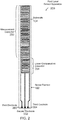
- FIG. 2 depicts a side view of a fluid level sensor apparatus (200) that includes the sense element (102) of FIG. 1 viewed from an alternative view of FIG. 1 .
- a particular configuration of the plurality of electrodes (106) of FIG. 1 is depicted which includes a first electrode (260), a second electrode (262), and a third electrode (264) forming two inter-digitated capacitors (i.e., a measurement capacitor (250) and a reference capacitor (254)).
- An inter-digitated planar capacitor is a particular capacitor structure in which a pair of electrodes form a two-dimensional array in which the electrodes are shaped like "fingers” or “combs” and are closely positioned opposed and parallel to each other and alternating in both dimensions of the two-dimensional array with a space therebetween forming an insulating gap.
- the measurement capacitor (250) and the reference capacitor (254) share the second electrode (262). While FIG. 2 illustrates one exemplary geometric configuration for the plurality of electrodes, those skilled in the art will recognize that other geometries may be used and all such alternative geometries are within the scope of the present invention. For example, in alternative configurations, the measurement capacitor (250) and the reference capacitor (254) do not share a common electrode.
- the measurement capacitor (250) is positioned such that the range of fluid levels desired to be detected is within the array of the measurement capacitor.
- the array of the measurement capacitor refers to the area of the capacitor in which the electrical field generated by the electrodes interact.
- the array of the measurement capacitor is of a size and in a position to correspond to the changes in position of the surface of the fluid as the surface of the fluid moves from a lowest detectable level to a highest detectable level.
- the capacitance of the measurement capacitor changes linearly with the level of the surface of the fluid.
- the capacitance measured across the two electrodes of the measurement capacitor increases because the dielectric constant of the oil is higher than the air that it replaces.
- the dielectric constant of the oil-based fluid may be different enough from the dielectric constant of air to enable the measurement capacitor (250) to indicate fluid level changes as changes in measured capacitance.
- the reference capacitor (254) is positioned in the lower section of the substrate (104) such that the reference capacitor (254) remains completely immersed in the fluid when the apparatus (200) is inserted into the fluid.
- the reference capacitor (254) provides an estimate of the dielectric constant of the fluid in the fluid cavity.
- a fluid level sensor apparatus (100) may include circuitry that compensates the capacitance of the measurement capacitor (250) with the output of the reference capacitor (254).
- a fluid level sensor apparatus may be formed from a sense element having only a measurement capacitor and a reference capacitor wherein the level of fluid is determined from the capacitance of the measurement capacitor and is compensated by the amount and rate of change of the capacitance of the reference capacitor.
- the outputs of the measurement capacitor (250) and the reference capacitor (254) may be coupled to signal processing circuitry (not shown) to determine the calibrated capacitance of the measurement capacitor (250) and the reference capacitor (254) when the sense element (102) is positioned within the fluid cavity (e.g., the fluid cavity (112) of FIG. 1 ) such that the reference capacitor (254) is submersed in the fluid and the fluid surface is in contact with the measurement capacitor (250).
- the circuitry may be configured to dynamically select the electrodes for the measurement capacitor (250) and the reference capacitor (254).
- the circuitry may also be configured to measure the capacitance of each capacitor (e.g., the measurement capacitor (250) and the reference capacitor (254)) and generate a digitized sensor voltage representing the capacitance of each capacitor.
- the circuitry is configured to calculate the level of the fluid within the fluid container as a linear function of the capacitance of the measurement capacitor (250) compensated by the amount and rate of change of the capacitance of the reference capacitor (254).
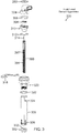
- FIG. 3 depicts an isometric view of a fluid level sensor apparatus (300) before being assembled, according to one embodiment of the present disclosure.
- the apparatus (300) includes a base connector (304) that mates with a customer harness to deliver inputs and outputs from the apparatus to another electrical device, such as a vehicle's power-train control module (PCM).
- PCM power-train control module
- the base connector (304) has a substantial 90 degree mounting orientation. Readers of skill in the art will realize that the base connector may be configured for alternative mounting orientations, according to embodiments of the present disclosure.
- the base connector (304) includes insert-molded terminals for mating with an electronic module assembly (EMA) (306), which in turn makes electrical connection to both a sense element (390), via an array of edge clips (314), and a metallic housing (320).
- EMA electronic module assembly
- the metallic housing (320) may accommodate an array of mounting techniques. Examples of mounting techniques include threaded, bracketed, grommeted, quarter-turn, and others as will occur to those of skill in the art.
- the sense element (390) includes two inter-digitated planar capacitors (a measurement capacitor (392) and a reference capacitor (394)).
- the measurement capacitor (392) and the reference capacitor (394) are passivated with a passivation layer and an oleophobic coating is applied over the passivation layer.
- the capacitors (392, 394) may not be passivated nor have an oleophobic coating applied.
- one of the capacitors (e.g., the reference capacitor (392)) is designed to remain submerged at all times in the application fluid, so as to track fluid capacitance over temperature and fluid life.
- the other capacitor e.g., the measurement capacitor (394)
- the output of the measurement capacitor (394) varies as a function of the change in level of the fluid.
- the capacitance change of the reference capacitor (392) allows the ASIC to properly adjust the fluid level signal generated by the measurement capacitor (394) to generate a compensated fluid level signal indicating a level of the fluid relative to the apparatus despite temperature or fluid aging.
- an analog or digital capacitive application specific integrated circuit is mounted onto the EMA (306) and is configured to process the outputs of the plurality of electrodes on the sense element (390).
- the EMA (306) includes signal processing circuitry coupled to the electrodes for converting the capacitance signals received from the sense element (390) into a linear ratio-metric analog voltage or digital output that indicates a level of the fluid relative to the apparatus.
- the outputs of the measurement capacitor (394) and the reference capacitor (392) may be coupled to circuitry on the EMA (306) to determine the calibrated capacitance of the measurement capacitor (394) and the reference capacitor (392) when the sense element (390) is positioned within the fluid cavity (e.g., the fluid cavity (112) of FIG. 1 ) such that the reference capacitor (392) is submersed in the fluid and the fluid surface is in contact with the measurement capacitor (394).
- the fluid cavity e.g., the fluid cavity (112) of FIG. 1
- the circuitry on the EMA (306) may be configured to dynamically select the electrodes for the measurement capacitor (394) and the reference capacitor (392).
- the circuitry on the EMA (306) may also be configured to measure the capacitance of each capacitor (e.g., the measurement capacitor (394) and the reference capacitor (392)) and generate a digitized sensor voltage representing the capacitance of each capacitor.
- the circuitry on the EMA (306) is configured to calculate the level of the fluid within the fluid container as a linear function of the capacitance of the measurement capacitor (394) compensated by the amount and rate of change of the capacitance of the reference capacitor (392).
- the circuitry may use the reference capacitor (392) to correct for differences in the dielectric constant between various oils and changes to the dielectric constant of the oil over different temperatures and over time.
- the circuitry on the EMA (306) may include a temperature sensor or be coupled to an external temperature sensor.
- the circuitry may provide the output of the temperature sensors to other devices, such as an automobile PCM, along with the output of the capacitive sensor (e.g., the sense element 102).
- the position of the sense element (390) and internal seal (312) are controlled by a carrier (310), which is mated to the base connector (304) via snap fingers.
- the internal seal is seated between one of the faces of the carrier (310) and the floor of the metallic housing (320) to ensure a proper fluid media seal.
- the apparatus (300) includes potting (308) which attaches to the carrier (310) to prevent leakage around the rectangular cross-section of the substrate.
- the sense element (390) is encased by a metallic shield (326).
- the metallic shield (326) reduces stray electromagnetic interference of the inter-digitated planar capacitors (392, 394) from outside the metallic shield (326).
- the metallic shield (326) also confines the capacitance field which makes this apparatus immune to variations to fluid container shape, size, and bill of material.
- the metallic shield (326) may also be configured to provide a mechanical support for the sense element (390).
- the metallic shield may include one or more ribs to reduce movement of the sense element within the cavity of the metallic shield.
- the metallic shield (326) includes at least one ventilation hole (not shown) and one or more inlet holes (324) for allowing fluid and air to move from the fluid container outside the metallic shield (326) into the fluid cavity inside the metallic shield (326).
- the shapes and sizes of the inlet holes may be optimized for mechanical filtering of the fluid level during dynamic environmental conditions.
- the holes may be shaped and sized to reduce the effects of fluid sloshing on the level measurements.
- the metallic shield (326) includes tails (328) that may be crimped during assembly.
- a support cap (330) may also be added to the end of the shield to provide additional mechanical support to the sense element (390).
- the support cap (330) may include a slot (332) to keep the sense element from moving within the cavity of the metallic shield (326).
- the one or more ventilation holes may be part of the support cap. Readers of skill in the art will realize that all of the components of the apparatus (300) may be optimized for application media and environmental media. For example, additional external seals and dispensed sealants may be added depending on environmental exposure.
- FIG. 4 depicts an isometric view of the fluid level sensor apparatus (300) of FIG. 3 , after being assembled.
- the environmental seal (302), the base connector (304), the EMA (306), the potting (308), the carrier (310), the internal seal (312), the edge clips (314), the sense element (390) are assembled and coupled to the metallic housing (320) and the mounting bracket (318).
- the metallic housing (320) is also coupled to the metallic shield (326) with the external seal (322) providing a means to prevent leakage of media fluid.
- the ends of the shield may be closed to hold the support cap in place.
- FIG. 5 depicts an isometric view of a fluid level sensor apparatus (500) before being assembled, according to one embodiment of the present disclosure.
- the apparatus (500) includes the environmental seal (302), the EMA (306), the potting (308), the carrier (310), the internal seal (312), the edge clips (314), the sense element (390), the metallic housing (320), the mounting bracket (318), the metallic shield (326), and the external seal (322) of the apparatus of FIG. 3 .
- the apparatus (500) includes an alternative base connector (504), which is configured to mate with a customer harness to deliver inputs and outputs from the apparatus (500) to another electrical device, such as a vehicle's power-train control module (PCM).
- the base connector (504) has a substantially straight mounting orientation. Readers of skill in the art will realize that the base connector may be configured for alternative mounting orientations, according to embodiments of the present disclosure.
- the base connector (504) includes insert-molded terminals for mating with the electronic module assembly (EMA) (306). Readers of skill in the art that the base connector (504) is just an example of one of many different types of connectors that can be used to couple a customer harness to the apparatus (500).
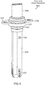
- FIG. 6 depicts an isometric view of the fluid level sensor apparatus (500) of FIG. 5 , after being assembled.
- the environmental seal (302), the base connector (504), the EMA (306), the potting (308), the carrier (310), the internal seal (312), the edge clips (314), the sense element (390) are assembled and coupled to the metallic housing (320) and the mounting bracket (318).
- the metallic housing (320) is also coupled to the metallic shield (326) with the external seal (322) providing a means to prevent leakage of media fluid.
- the ends of the shield may be closed to hold the support cap in place.
- FIG. 7 depicts an isometric view of a fluid level sensor apparatus (700) before being assembled, according to one embodiment of the present disclosure.
- the apparatus (700) includes a plastic housing (708) which mates with a customer harness to deliver inputs and outputs from the apparatus to another electrical device.
- the plastic housing (708) includes insert-molded terminals for mating with an electronic module assembly (EMA) (706), which in turn makes electrical connection to a sense element (390), via an array of edge clips (710).
- EMA electronic module assembly
- the EMA (706) is protected by a cover (704).
- the apparatus (700) also includes a plurality of bushings (702) for use in mounting the plastic housing (708) to an assembly, such as an oil pan.
- an application specific integrated circuit (ASIC) (705) is mounted onto the EMA (706) and is configured to convert capacitance signals received from the sense element (390) into a linear ratio-metric analog voltage and digital output that indicates a level of the fluid relative to the apparatus.
- the outputs of the measurement capacitor (394) and the reference capacitor (392) may be coupled to the ASIC (705) to determine the calibrated capacitance of the measurement capacitor (394) and the reference capacitor (392) when the sense element (390) is positioned within the fluid cavity (e.g., the fluid cavity (112) of FIG. 1 ) such that the reference capacitor (392) is submersed in the fluid and the fluid surface is in contact with the measurement capacitor (394).
- the ASIC (705) may be configured to dynamically select the electrodes for the measurement capacitor (394) and the reference capacitor (392).
- the ASIC (705) may also be configured to measure the capacitance of each capacitor (e.g., the measurement capacitor (394) and the reference capacitor (392)) and generate a digitized sensor voltage representing the capacitance of each capacitor.
- the ASIC (705) is configured to calculate the level of the fluid within the fluid container as a linear function of the capacitance of the measurement capacitor (394) compensated by the amount and rate of change of the capacitance of the reference capacitor (392).
- the circuitry may use the reference capacitor (392) to correct for differences in the dielectric constant between various oils and changes to the dielectric constant of the oil over different temperatures and over time.
- the sense element (390) includes two inter-digitated planar capacitors (392, 394).
- one of the capacitors e.g., the reference capacitor (392)
- the other capacitor e.g., the measurement capacitor (394)
- the output of the measurement capacitor (394) varies as a function of the change in level of the fluid.
- the capacitance change of the reference capacitor (392) allows the ASIC to properly adjust the fluid level signal generated by the measurement capacitor (394) to generate a compensated fluid level signal indicating a level of the fluid relative to the apparatus.
- the sense element (390) is encased by a metallic shield (718).
- the metallic shield (718) reduces stray electromagnetic interference of the inter-digitated planar capacitors (392, 394) from outside the metallic shield (718).
- the metallic shield (718) also confines capacitance field which makes this apparatus immune to variations to fluid container shape, size, and bill of material.
- the metallic shield (718) may also be configured to provide a mechanical support for the sense element (390).
- the metallic shield may include one or more ribs (714) to reduce movement of the sense element (390) within the cavity of the metallic shield (718).
- the metallic shield (718) includes at least one ventilation hole (not shown) and one or more inlet holes (716) for allowing fluid and air to move from the fluid container outside the metallic shield (718) into the fluid cavity inside the metallic shield (718).
- the shapes and sizes of the inlet holes may be optimized for mechanical filtering of the fluid level during dynamic environmental conditions.
- the holes may be shaped and sized to reduce the effects of fluid sloshing on the level measurements.
- a support cap (720) may also be added to the end of the shield to provide additional mechanical support to the sense element (390).
- the support cap (720) of FIG. 7 includes a slot (722) for holding the sense element (390).
- the slot (722) of FIG. 7 may keep the sense element (390) from moving within the cavity of the metallic shield (718). Readers of skill in the art will realize that additional external seals and dispensed sealants may be added depending on environmental exposure.
- FIG. 8 depicts an isometric view of the fluid level sensor apparatus of FIG. 7 , after being assembled.
- the sense element (390) are coupled to the EMA (706) via the edge clips (710) and is encased within the metallic shield (718).
- the metallic shield (718) is fastened to the plastic housing (708), which also positions the external face seal (724) and the external radial seal (726).
- the support cap (720) is attached to the metallic shield (718) and provides mechanical support for the sense element (390) within the metallic shield (718).
- the EMA (706) and the ASIC (705) are protected by the cover (704).
- FIG. 9 depicts an isometric view of a fluid level sensor apparatus before being assembled, according to one embodiment of the present disclosure.
- the apparatus (900) includes a base connector (904) which mates with a customer harness to deliver inputs and outputs from the apparatus to another electrical device, such as a vehicle's power-train control module (PCM).
- the base connector (904) includes insert-molded terminals for mating with an electronic module assembly (EMA) (906), which in turn makes electrical connection to both a sense element (390), via an array of edge clips (914), and a metallic housing (918).
- EMA electronic module assembly
- the metallic housing (918) may accommodate an array of mounting techniques. Examples of mounting techniques include threaded, bracketed, grommeted, quarter-turn, and others as will occur to those of skill in the art.
- an application specific integrated circuit is mounted onto the EMA (906) and is configured to convert capacitance signals received from the sense element (390) into a linear ratio-metric analog voltage or digital output that indicates a level of the fluid relative to the apparatus.
- ASIC application specific integrated circuit
- the sense element (390) includes two inter-digitated planar capacitors (392, 394).
- one of the capacitors e.g., the reference capacitor (392)
- the other capacitor e.g., the measurement capacitor (394)
- the output of the measurement capacitor (394) varies as a function of the change in level of the fluid.
- the capacitance change of the reference capacitor (392) allows the ASIC to properly adjust the fluid level signal generated by the measurement capacitor (394) to generate a compensated fluid level signal indicating a level of the fluid relative to the apparatus.
- the position of the sense element (390) and internal seal (912) are controlled by a carrier (910), which is mated to the base connector (904).
- the internal seal (912) is seated between one of the faces of the carrier (910) and the floor of the metallic housing (918) to ensure a proper fluid media seal.
- the apparatus (900) includes potting (908) which is dispensed into a cavity within the carrier (910) to prevent leakage around the rectangular cross-section of the ceramic element.
- the sense element (390) is encased by a metallic shield (926).
- the metallic shield (926) reduces interference with the two inter-digitated planar capacitors (392, 394) from outside the metallic shield (926).
- the metallic shield also confines electromagnetic field which makes this apparatus immune to variations to fluid container shape and dimensions.
- the metallic shield (926) may also be configured to provide a mechanical support for the sense element (390).
- the metallic shield may include one or more ribs to reduce movement of the sense element within the cavity of the metallic shield.
- the metallic shield (926) includes at least one ventilation hole (not shown) and one or more inlet holes (924) for allowing fluid and air to move from the fluid container outside the metallic shield (926) into the fluid cavity inside the metallic shield (926).
- the shapes and sizes of the inlet holes may be optimized for mechanical filtering of the fluid level during dynamic environmental conditions.
- the holes may be shaped and sized to reduce the effects of fluid sloshing on the level measurements.
- a support cap (928) may also be added to the end of the shield to provide additional mechanical support to the sense element (390).
- the one or more ventilation holes may be part of the support cap.
- the metallic shield (926) may also be configured to provide a mechanical support for the sense element (390).
- the metallic shield (926) includes a slot (930) to reduce movement of the sense element (390) within the cavity of the metallic shield (926). Readers of skill in the art will realize that additional external seals and dispensed sealants may be added depending on environmental exposure.
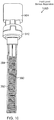
- FIG. 10 depicts an isometric view of a fluid level sensor apparatus (1000).
- the base connector (904), the carrier (910), and the sense element (390) of FIG. 9 are coupled together.
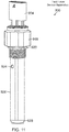
- FIG. 11 depicts an isometric view of the oleophobic fluid level sensor apparatus of FIG. 9 , after being assembled.
- the environmental seal (902), the base connector (904), the EMA (906), the potting (908), the carrier (910), the internal seal (912), the edge clips (914), the sense element (390) are assembled and coupled to the metallic housing (918).
- the metallic housing (918) is also coupled to the metallic shield (926) with the external seal (920) providing a seal to prevent leakage of any media fluid.
- the ends of the shield may be closed to hold the support cap in place.
Landscapes
- Physics & Mathematics (AREA)
- Engineering & Computer Science (AREA)
- Power Engineering (AREA)
- Electromagnetism (AREA)
- Thermal Sciences (AREA)
- Fluid Mechanics (AREA)
- General Physics & Mathematics (AREA)
- Mechanical Engineering (AREA)
- General Engineering & Computer Science (AREA)
- Measurement Of Levels Of Liquids Or Fluent Solid Materials (AREA)
- Investigating Or Analyzing Materials By The Use Of Electric Means (AREA)
Applications Claiming Priority (1)
| Application Number | Priority Date | Filing Date | Title |
|---|---|---|---|
| US16/117,240 US20200072651A1 (en) | 2018-08-30 | 2018-08-30 | Fluid level sensor apparatus with inter-digitated planr capacitors for directly inserting into a fluid |
Publications (2)
| Publication Number | Publication Date |
|---|---|
| EP3617666A2 true EP3617666A2 (de) | 2020-03-04 |
| EP3617666A3 EP3617666A3 (de) | 2020-05-27 |
Family
ID=66668715
Family Applications (1)
| Application Number | Title | Priority Date | Filing Date |
|---|---|---|---|
| EP19176251.7A Withdrawn EP3617666A3 (de) | 2018-08-30 | 2019-05-23 | Fluidstandsensorvorrichtung mit ineinandergreifenden planaren kondensatoren zum direkten einsetzen in ein fluid |
Country Status (4)
| Country | Link |
|---|---|
| US (1) | US20200072651A1 (de) |
| EP (1) | EP3617666A3 (de) |
| KR (1) | KR20200026067A (de) |
| CN (1) | CN110873597A (de) |
Cited By (1)
| Publication number | Priority date | Publication date | Assignee | Title |
|---|---|---|---|---|
| CN116359569A (zh) * | 2021-12-27 | 2023-06-30 | 财团法人工业技术研究院 | 探针卡 |
Families Citing this family (11)
| Publication number | Priority date | Publication date | Assignee | Title |
|---|---|---|---|---|
| EP3367075B1 (de) * | 2017-02-22 | 2019-12-11 | Zodiac Aerotechnics | Kondensatorbrennstoffsonde |
| US12179577B2 (en) * | 2018-12-28 | 2024-12-31 | Tf Technologies, Llc | Fuel measurement device with fuel passage and fuel level sensor |
| US11674838B2 (en) * | 2019-04-04 | 2023-06-13 | Poseidon Systems Llc | Capacitive fringe field oil level sensor with integrated humidity and temperature sensing |
| US11415538B2 (en) * | 2020-03-06 | 2022-08-16 | Applied Materials, Inc. | Capacitive sensor housing for chamber condition monitoring |
| US11581206B2 (en) * | 2020-03-06 | 2023-02-14 | Applied Materials, Inc. | Capacitive sensor for chamber condition monitoring |
| CN118103239A (zh) * | 2021-10-15 | 2024-05-28 | 海拉有限双合股份公司 | 冷却剂箱、冷却剂引导系统和机动车 |
| JP2023077606A (ja) * | 2021-11-25 | 2023-06-06 | セイコーエプソン株式会社 | 貯蔵装置、及び、液体吐出装置 |
| CN114111965B (zh) * | 2021-12-23 | 2025-06-03 | 山东胜利通海集团东营天蓝节能科技有限公司 | 一种基于叉指电容的液位测量传感器及液位测量方法 |
| CN115683275A (zh) * | 2022-11-02 | 2023-02-03 | 河源市嘉辰科技有限公司 | 交扣叉指电极结构、电容式水位传感器及精密水位检测装置 |
| CN116759683A (zh) * | 2023-08-24 | 2023-09-15 | 宁德时代新能源科技股份有限公司 | 电池单体、电解液液位高度测试方法、电池和用电装置 |
| CN119147072B (zh) * | 2024-11-11 | 2025-03-04 | 四川泛华航空仪表电器有限公司 | 一种航空油箱用非接触式油位测量装置及测量方法 |
Citations (3)
| Publication number | Priority date | Publication date | Assignee | Title |
|---|---|---|---|---|
| US20110043224A1 (en) * | 2009-08-18 | 2011-02-24 | 3M Innovative Properties Company | Capacitive oil quality monitoring sensor with fluorinated barrier coating |
| US20110120219A1 (en) * | 2004-12-22 | 2011-05-26 | Inergy Auto. Systems Research (Societe Anonyme) | Capacitive liquid level sensor |
| US20140375321A1 (en) * | 2013-06-20 | 2014-12-25 | Aisan Kogyo Kabushiki Kaisha | Sensor device |
Family Cites Families (6)
| Publication number | Priority date | Publication date | Assignee | Title |
|---|---|---|---|---|
| JPS60192228A (ja) * | 1984-03-14 | 1985-09-30 | Tokyo Tatsuno Co Ltd | 液深測定用電極 |
| DE19938270A1 (de) * | 1999-08-12 | 2001-02-15 | Abb Research Ltd | Kapazitiver Füllstandssensor mit Dielektrischer Beschichtung |
| US6539797B2 (en) * | 2001-06-25 | 2003-04-01 | Becs Technology, Inc. | Auto-compensating capacitive level sensor |
| JP2013228365A (ja) * | 2012-03-29 | 2013-11-07 | Aisan Ind Co Ltd | 液位計測装置 |
| JP2014021073A (ja) * | 2012-07-23 | 2014-02-03 | Aisan Ind Co Ltd | 液体センサ |
| GB2519783A (en) * | 2013-10-30 | 2015-05-06 | Airbus Operations Ltd | Capacitive liquid level sensor |
-
2018
- 2018-08-30 US US16/117,240 patent/US20200072651A1/en not_active Abandoned
-
2019
- 2019-05-23 EP EP19176251.7A patent/EP3617666A3/de not_active Withdrawn
- 2019-07-12 CN CN201910628560.4A patent/CN110873597A/zh active Pending
- 2019-08-21 KR KR1020190102308A patent/KR20200026067A/ko not_active Withdrawn
Patent Citations (3)
| Publication number | Priority date | Publication date | Assignee | Title |
|---|---|---|---|---|
| US20110120219A1 (en) * | 2004-12-22 | 2011-05-26 | Inergy Auto. Systems Research (Societe Anonyme) | Capacitive liquid level sensor |
| US20110043224A1 (en) * | 2009-08-18 | 2011-02-24 | 3M Innovative Properties Company | Capacitive oil quality monitoring sensor with fluorinated barrier coating |
| US20140375321A1 (en) * | 2013-06-20 | 2014-12-25 | Aisan Kogyo Kabushiki Kaisha | Sensor device |
Cited By (1)
| Publication number | Priority date | Publication date | Assignee | Title |
|---|---|---|---|---|
| CN116359569A (zh) * | 2021-12-27 | 2023-06-30 | 财团法人工业技术研究院 | 探针卡 |
Also Published As
| Publication number | Publication date |
|---|---|
| EP3617666A3 (de) | 2020-05-27 |
| KR20200026067A (ko) | 2020-03-10 |
| CN110873597A (zh) | 2020-03-10 |
| US20200072651A1 (en) | 2020-03-05 |
Similar Documents
| Publication | Publication Date | Title |
|---|---|---|
| EP3617666A2 (de) | Fluidstandsensorvorrichtung mit ineinandergreifenden planaren kondensatoren zum direkten einsetzen in ein fluid | |
| CN1224826C (zh) | 液面传感器 | |
| US7997132B2 (en) | Capacitive sensor assembly for determining relative position | |
| JP6614747B2 (ja) | 圧力検知モジュールおよびこのような圧力検知モジュールを備えた圧力センサ装置 | |
| US7963164B2 (en) | Capacitive sensor assembly for determining level of fluent materials | |
| US5051921A (en) | Method and apparatus for detecting liquid composition and actual liquid level | |
| KR100968055B1 (ko) | 압력 센서 모듈 | |
| US6539797B2 (en) | Auto-compensating capacitive level sensor | |
| US20050280424A1 (en) | Device and method for measuring capacitance and device for determing the level of a liquid using one such device | |
| US6178818B1 (en) | Capacitive filling level sensor | |
| US6829820B2 (en) | Method of manufacturing temperature sensor and temperature sensor manufactured thereby | |
| CN111094960B (zh) | 用于测量分析气体的浓度的气体传感器 | |
| CN1354830A (zh) | 压力传感器 | |
| JP4716146B2 (ja) | 液体性状センサ | |
| US7800379B2 (en) | Fuel sensor | |
| US4272986A (en) | Method and means for measuring moisture content of hermetic semiconductor devices | |
| US11118993B2 (en) | Device for measuring a physical parameter of a fluid of a motor vehicle circuit | |
| WO1999010714A1 (en) | A compensated capacitive liquid level sensor | |
| US6625896B1 (en) | Electrolytic tilt sensor and method for manufacturing same | |
| EP3714259B1 (de) | Korrosionsmessvorrichtung | |
| US20040231402A1 (en) | Sensor element, in particular an oil condition sensor element, and a fluid sensor having a sensor element of this type | |
| WO2002016888A1 (en) | Level sensor | |
| CN202853838U (zh) | 机动车用真空压力传感器装置 | |
| US6583631B2 (en) | Precise dielectric constant sensor | |
| EP0635724B1 (de) | Elektrostatische Messung des Erdepotentiales |
Legal Events
| Date | Code | Title | Description |
|---|---|---|---|
| PUAI | Public reference made under article 153(3) epc to a published international application that has entered the european phase |
Free format text: ORIGINAL CODE: 0009012 |
|
| STAA | Information on the status of an ep patent application or granted ep patent |
Free format text: STATUS: THE APPLICATION HAS BEEN PUBLISHED |
|
| AK | Designated contracting states |
Kind code of ref document: A2 Designated state(s): AL AT BE BG CH CY CZ DE DK EE ES FI FR GB GR HR HU IE IS IT LI LT LU LV MC MK MT NL NO PL PT RO RS SE SI SK SM TR |
|
| AX | Request for extension of the european patent |
Extension state: BA ME |
|
| PUAL | Search report despatched |
Free format text: ORIGINAL CODE: 0009013 |
|
| AK | Designated contracting states |
Kind code of ref document: A3 Designated state(s): AL AT BE BG CH CY CZ DE DK EE ES FI FR GB GR HR HU IE IS IT LI LT LU LV MC MK MT NL NO PL PT RO RS SE SI SK SM TR |
|
| AX | Request for extension of the european patent |
Extension state: BA ME |
|
| RIC1 | Information provided on ipc code assigned before grant |
Ipc: G01F 23/26 20060101AFI20200417BHEP |
|
| STAA | Information on the status of an ep patent application or granted ep patent |
Free format text: STATUS: REQUEST FOR EXAMINATION WAS MADE |
|
| 17P | Request for examination filed |
Effective date: 20201127 |
|
| RBV | Designated contracting states (corrected) |
Designated state(s): AL AT BE BG CH CY CZ DE DK EE ES FI FR GB GR HR HU IE IS IT LI LT LU LV MC MK MT NL NO PL PT RO RS SE SI SK SM TR |
|
| STAA | Information on the status of an ep patent application or granted ep patent |
Free format text: STATUS: EXAMINATION IS IN PROGRESS |
|
| 17Q | First examination report despatched |
Effective date: 20210323 |
|
| STAA | Information on the status of an ep patent application or granted ep patent |
Free format text: STATUS: THE APPLICATION IS DEEMED TO BE WITHDRAWN |
|
| 18D | Application deemed to be withdrawn |
Effective date: 20210803 |