EP3617616A1 - Refrigeration cycle device - Google Patents
Refrigeration cycle device Download PDFInfo
- Publication number
- EP3617616A1 EP3617616A1 EP17907530.4A EP17907530A EP3617616A1 EP 3617616 A1 EP3617616 A1 EP 3617616A1 EP 17907530 A EP17907530 A EP 17907530A EP 3617616 A1 EP3617616 A1 EP 3617616A1
- Authority
- EP
- European Patent Office
- Prior art keywords
- refrigerant
- heat exchanger
- valve
- compressor
- defrosting
- Prior art date
- Legal status (The legal status is an assumption and is not a legal conclusion. Google has not performed a legal analysis and makes no representation as to the accuracy of the status listed.)
- Granted
Links
Images



Classifications
-
- F—MECHANICAL ENGINEERING; LIGHTING; HEATING; WEAPONS; BLASTING
- F25—REFRIGERATION OR COOLING; COMBINED HEATING AND REFRIGERATION SYSTEMS; HEAT PUMP SYSTEMS; MANUFACTURE OR STORAGE OF ICE; LIQUEFACTION SOLIDIFICATION OF GASES
- F25B—REFRIGERATION MACHINES, PLANTS OR SYSTEMS; COMBINED HEATING AND REFRIGERATION SYSTEMS; HEAT PUMP SYSTEMS
- F25B13/00—Compression machines, plants or systems, with reversible cycle
-
- B—PERFORMING OPERATIONS; TRANSPORTING
- B60—VEHICLES IN GENERAL
- B60H—ARRANGEMENTS OF HEATING, COOLING, VENTILATING OR OTHER AIR-TREATING DEVICES SPECIALLY ADAPTED FOR PASSENGER OR GOODS SPACES OF VEHICLES
- B60H1/00—Heating, cooling or ventilating devices
- B60H1/22—Heating, cooling or ventilating devices the heat source being other than the propulsion plant
-
- F—MECHANICAL ENGINEERING; LIGHTING; HEATING; WEAPONS; BLASTING
- F25—REFRIGERATION OR COOLING; COMBINED HEATING AND REFRIGERATION SYSTEMS; HEAT PUMP SYSTEMS; MANUFACTURE OR STORAGE OF ICE; LIQUEFACTION SOLIDIFICATION OF GASES
- F25B—REFRIGERATION MACHINES, PLANTS OR SYSTEMS; COMBINED HEATING AND REFRIGERATION SYSTEMS; HEAT PUMP SYSTEMS
- F25B30/00—Heat pumps
- F25B30/02—Heat pumps of the compression type
-
- F—MECHANICAL ENGINEERING; LIGHTING; HEATING; WEAPONS; BLASTING
- F25—REFRIGERATION OR COOLING; COMBINED HEATING AND REFRIGERATION SYSTEMS; HEAT PUMP SYSTEMS; MANUFACTURE OR STORAGE OF ICE; LIQUEFACTION SOLIDIFICATION OF GASES
- F25B—REFRIGERATION MACHINES, PLANTS OR SYSTEMS; COMBINED HEATING AND REFRIGERATION SYSTEMS; HEAT PUMP SYSTEMS
- F25B41/00—Fluid-circulation arrangements
- F25B41/30—Expansion means; Dispositions thereof
- F25B41/39—Dispositions with two or more expansion means arranged in series, i.e. multi-stage expansion, on a refrigerant line leading to the same evaporator
-
- F—MECHANICAL ENGINEERING; LIGHTING; HEATING; WEAPONS; BLASTING
- F25—REFRIGERATION OR COOLING; COMBINED HEATING AND REFRIGERATION SYSTEMS; HEAT PUMP SYSTEMS; MANUFACTURE OR STORAGE OF ICE; LIQUEFACTION SOLIDIFICATION OF GASES
- F25B—REFRIGERATION MACHINES, PLANTS OR SYSTEMS; COMBINED HEATING AND REFRIGERATION SYSTEMS; HEAT PUMP SYSTEMS
- F25B47/00—Arrangements for preventing or removing deposits or corrosion, not provided for in another subclass
- F25B47/02—Defrosting cycles
-
- F—MECHANICAL ENGINEERING; LIGHTING; HEATING; WEAPONS; BLASTING
- F25—REFRIGERATION OR COOLING; COMBINED HEATING AND REFRIGERATION SYSTEMS; HEAT PUMP SYSTEMS; MANUFACTURE OR STORAGE OF ICE; LIQUEFACTION SOLIDIFICATION OF GASES
- F25B—REFRIGERATION MACHINES, PLANTS OR SYSTEMS; COMBINED HEATING AND REFRIGERATION SYSTEMS; HEAT PUMP SYSTEMS
- F25B47/00—Arrangements for preventing or removing deposits or corrosion, not provided for in another subclass
- F25B47/02—Defrosting cycles
- F25B47/022—Defrosting cycles hot gas defrosting
- F25B47/025—Defrosting cycles hot gas defrosting by reversing the cycle
-
- F—MECHANICAL ENGINEERING; LIGHTING; HEATING; WEAPONS; BLASTING
- F25—REFRIGERATION OR COOLING; COMBINED HEATING AND REFRIGERATION SYSTEMS; HEAT PUMP SYSTEMS; MANUFACTURE OR STORAGE OF ICE; LIQUEFACTION SOLIDIFICATION OF GASES
- F25B—REFRIGERATION MACHINES, PLANTS OR SYSTEMS; COMBINED HEATING AND REFRIGERATION SYSTEMS; HEAT PUMP SYSTEMS
- F25B49/00—Arrangement or mounting of control or safety devices
- F25B49/02—Arrangement or mounting of control or safety devices for compression type machines, plants or systems
-
- F—MECHANICAL ENGINEERING; LIGHTING; HEATING; WEAPONS; BLASTING
- F25—REFRIGERATION OR COOLING; COMBINED HEATING AND REFRIGERATION SYSTEMS; HEAT PUMP SYSTEMS; MANUFACTURE OR STORAGE OF ICE; LIQUEFACTION SOLIDIFICATION OF GASES
- F25B—REFRIGERATION MACHINES, PLANTS OR SYSTEMS; COMBINED HEATING AND REFRIGERATION SYSTEMS; HEAT PUMP SYSTEMS
- F25B2400/00—Component parts or details not otherwise provided for in this subclass
- F25B2400/24—Thermal storage element
-
- F—MECHANICAL ENGINEERING; LIGHTING; HEATING; WEAPONS; BLASTING
- F25—REFRIGERATION OR COOLING; COMBINED HEATING AND REFRIGERATION SYSTEMS; HEAT PUMP SYSTEMS; MANUFACTURE OR STORAGE OF ICE; LIQUEFACTION SOLIDIFICATION OF GASES
- F25B—REFRIGERATION MACHINES, PLANTS OR SYSTEMS; COMBINED HEATING AND REFRIGERATION SYSTEMS; HEAT PUMP SYSTEMS
- F25B2600/00—Control issues
- F25B2600/25—Control of valves
- F25B2600/2501—Bypass valves
-
- F—MECHANICAL ENGINEERING; LIGHTING; HEATING; WEAPONS; BLASTING
- F25—REFRIGERATION OR COOLING; COMBINED HEATING AND REFRIGERATION SYSTEMS; HEAT PUMP SYSTEMS; MANUFACTURE OR STORAGE OF ICE; LIQUEFACTION SOLIDIFICATION OF GASES
- F25B—REFRIGERATION MACHINES, PLANTS OR SYSTEMS; COMBINED HEATING AND REFRIGERATION SYSTEMS; HEAT PUMP SYSTEMS
- F25B2700/00—Sensing or detecting of parameters; Sensors therefor
- F25B2700/19—Pressures
- F25B2700/193—Pressures of the compressor
- F25B2700/1931—Discharge pressures
-
- F—MECHANICAL ENGINEERING; LIGHTING; HEATING; WEAPONS; BLASTING
- F25—REFRIGERATION OR COOLING; COMBINED HEATING AND REFRIGERATION SYSTEMS; HEAT PUMP SYSTEMS; MANUFACTURE OR STORAGE OF ICE; LIQUEFACTION SOLIDIFICATION OF GASES
- F25B—REFRIGERATION MACHINES, PLANTS OR SYSTEMS; COMBINED HEATING AND REFRIGERATION SYSTEMS; HEAT PUMP SYSTEMS
- F25B2700/00—Sensing or detecting of parameters; Sensors therefor
- F25B2700/19—Pressures
- F25B2700/193—Pressures of the compressor
- F25B2700/1933—Suction pressures
-
- F—MECHANICAL ENGINEERING; LIGHTING; HEATING; WEAPONS; BLASTING
- F25—REFRIGERATION OR COOLING; COMBINED HEATING AND REFRIGERATION SYSTEMS; HEAT PUMP SYSTEMS; MANUFACTURE OR STORAGE OF ICE; LIQUEFACTION SOLIDIFICATION OF GASES
- F25B—REFRIGERATION MACHINES, PLANTS OR SYSTEMS; COMBINED HEATING AND REFRIGERATION SYSTEMS; HEAT PUMP SYSTEMS
- F25B2700/00—Sensing or detecting of parameters; Sensors therefor
- F25B2700/21—Temperatures
- F25B2700/2111—Temperatures of a heat storage receiver
-
- F—MECHANICAL ENGINEERING; LIGHTING; HEATING; WEAPONS; BLASTING
- F25—REFRIGERATION OR COOLING; COMBINED HEATING AND REFRIGERATION SYSTEMS; HEAT PUMP SYSTEMS; MANUFACTURE OR STORAGE OF ICE; LIQUEFACTION SOLIDIFICATION OF GASES
- F25B—REFRIGERATION MACHINES, PLANTS OR SYSTEMS; COMBINED HEATING AND REFRIGERATION SYSTEMS; HEAT PUMP SYSTEMS
- F25B2700/00—Sensing or detecting of parameters; Sensors therefor
- F25B2700/21—Temperatures
- F25B2700/2115—Temperatures of a compressor or the drive means therefor
- F25B2700/21151—Temperatures of a compressor or the drive means therefor at the suction side of the compressor
-
- F—MECHANICAL ENGINEERING; LIGHTING; HEATING; WEAPONS; BLASTING
- F25—REFRIGERATION OR COOLING; COMBINED HEATING AND REFRIGERATION SYSTEMS; HEAT PUMP SYSTEMS; MANUFACTURE OR STORAGE OF ICE; LIQUEFACTION SOLIDIFICATION OF GASES
- F25B—REFRIGERATION MACHINES, PLANTS OR SYSTEMS; COMBINED HEATING AND REFRIGERATION SYSTEMS; HEAT PUMP SYSTEMS
- F25B2700/00—Sensing or detecting of parameters; Sensors therefor
- F25B2700/21—Temperatures
- F25B2700/2115—Temperatures of a compressor or the drive means therefor
- F25B2700/21152—Temperatures of a compressor or the drive means therefor at the discharge side of the compressor
-
- F—MECHANICAL ENGINEERING; LIGHTING; HEATING; WEAPONS; BLASTING
- F25—REFRIGERATION OR COOLING; COMBINED HEATING AND REFRIGERATION SYSTEMS; HEAT PUMP SYSTEMS; MANUFACTURE OR STORAGE OF ICE; LIQUEFACTION SOLIDIFICATION OF GASES
- F25B—REFRIGERATION MACHINES, PLANTS OR SYSTEMS; COMBINED HEATING AND REFRIGERATION SYSTEMS; HEAT PUMP SYSTEMS
- F25B2700/00—Sensing or detecting of parameters; Sensors therefor
- F25B2700/21—Temperatures
- F25B2700/2116—Temperatures of a condenser
- F25B2700/21162—Temperatures of a condenser of the refrigerant at the inlet of the condenser
-
- F—MECHANICAL ENGINEERING; LIGHTING; HEATING; WEAPONS; BLASTING
- F25—REFRIGERATION OR COOLING; COMBINED HEATING AND REFRIGERATION SYSTEMS; HEAT PUMP SYSTEMS; MANUFACTURE OR STORAGE OF ICE; LIQUEFACTION SOLIDIFICATION OF GASES
- F25B—REFRIGERATION MACHINES, PLANTS OR SYSTEMS; COMBINED HEATING AND REFRIGERATION SYSTEMS; HEAT PUMP SYSTEMS
- F25B2700/00—Sensing or detecting of parameters; Sensors therefor
- F25B2700/21—Temperatures
- F25B2700/2116—Temperatures of a condenser
- F25B2700/21163—Temperatures of a condenser of the refrigerant at the outlet of the condenser
-
- F—MECHANICAL ENGINEERING; LIGHTING; HEATING; WEAPONS; BLASTING
- F25—REFRIGERATION OR COOLING; COMBINED HEATING AND REFRIGERATION SYSTEMS; HEAT PUMP SYSTEMS; MANUFACTURE OR STORAGE OF ICE; LIQUEFACTION SOLIDIFICATION OF GASES
- F25B—REFRIGERATION MACHINES, PLANTS OR SYSTEMS; COMBINED HEATING AND REFRIGERATION SYSTEMS; HEAT PUMP SYSTEMS
- F25B2700/00—Sensing or detecting of parameters; Sensors therefor
- F25B2700/21—Temperatures
- F25B2700/2117—Temperatures of an evaporator
- F25B2700/21174—Temperatures of an evaporator of the refrigerant at the inlet of the evaporator
-
- F—MECHANICAL ENGINEERING; LIGHTING; HEATING; WEAPONS; BLASTING
- F25—REFRIGERATION OR COOLING; COMBINED HEATING AND REFRIGERATION SYSTEMS; HEAT PUMP SYSTEMS; MANUFACTURE OR STORAGE OF ICE; LIQUEFACTION SOLIDIFICATION OF GASES
- F25B—REFRIGERATION MACHINES, PLANTS OR SYSTEMS; COMBINED HEATING AND REFRIGERATION SYSTEMS; HEAT PUMP SYSTEMS
- F25B2700/00—Sensing or detecting of parameters; Sensors therefor
- F25B2700/21—Temperatures
- F25B2700/2117—Temperatures of an evaporator
- F25B2700/21175—Temperatures of an evaporator of the refrigerant at the outlet of the evaporator
Definitions
- the present invention relates to a refrigeration cycle apparatus, and particularly to a refrigeration cycle apparatus that performs a defrosting operation utilizing an amount of heat stored in a heat storage body for removing frost formed on an outdoor heat exchanger.
- a refrigeration cycle apparatus using air as a heat source
- a prescribed temperature for example, 7°C
- frost forms on the outdoor heat exchanger.
- Formed frost blocks an air flow passage in the outdoor heat exchanger, and thereby the heating performance deteriorates. Accordingly, the defrosting operation for melting the frost has to be performed at regular time intervals.
- this defrosting operation has been performed using, as a heat source, an amount of heat stored in indoor air, an indoor heat exchanger, an indoor/outdoor connection pipe and a compressor by operating a refrigeration cycle apparatus while switching a four-way valve of the refrigeration cycle apparatus into a cooling side.
- indoor air is used as a heat source, and cold air is fed into the room that is supposed to be heated, so that the comfortableness inside the room is deteriorated.
- refrigerant is cooled by defrosting.
- the refrigerant flows through the indoor heat exchanger, the indoor/outdoor connection pipe and the compressor, the refrigerant removes heat from these components. Accordingly, when the defrosting operation is ended and the heating operation is resumed, the above-mentioned components have to be heated again, which delays the increasing rate of the temperature of warm air blowing into the room.
- a heat storage body is provided on a refrigeration cycle circuit. Heat is stored in the heat storage body during a heating operation. Then, the amount of stored heat is used as a heat source during a defrosting operation. Thereby, the defrosting performance is improved, the defrosting time is shortened, and liquid refrigerant is prevented from being returned to a compressor.
- PTL 1 Japanese Patent Laying-Open No. 2009-287903 (paragraph [0006], Fig. 1 )
- liquid refrigerant cannot be completely evaporated and suctioned into the compressor. Then, lubricating oil inside the compressor is diluted with the refrigerant and reduced in viscosity. This also causes a problem that lubrication is poor in a compression mechanism.
- An object of the present invention is to provide a refrigeration cycle apparatus characterized by shortening a defrosting time and accelerating recovery of the heating performance after the heating operation is resumed.
- the present disclosure relates to a refrigeration cycle apparatus.
- the refrigeration cycle apparatus includes: a refrigerant circuit through which refrigerant circulates in a forward direction or an opposite direction to the forward direction sequentially through a compressor, an indoor heat exchanger, a first expansion valve, a heat storage body, a second expansion valve, and an outdoor heat exchanger, and back to the compressor; and a four-way valve configured to change a circulation direction of the refrigerant.
- the refrigerant circuit includes a first refrigerant pipe, a second refrigerant pipe, a third refrigerant pipe, a fourth refrigerant pipe, a fifth refrigerant pipe, a bypass path, and a first on-off valve.
- the first refrigerant pipe extends from the outdoor heat exchanger through the first expansion valve, the heat storage body and the second expansion valve to the indoor heat exchanger.
- the second refrigerant pipe connects the four-way valve and the indoor heat exchanger.
- the third refrigerant pipe connects the four-way valve and the outdoor heat exchanger.
- the fourth refrigerant pipe connects a suction port of the compressor and the four-way valve.
- the fifth refrigerant pipe connects a discharge port of the compressor and the four-way valve.
- the bypass path branches off from a first portion in the first refrigerant pipe and leads to the fourth refrigerant pipe, and the first portion connects the indoor heat exchanger and the first expansion valve.
- the first on-off valve is provided in the bypass path.
- a heat storage body is disposed on a refrigerant circuit, which connects an indoor heat exchanger and an outdoor heat exchanger, so as to be located between two expansion valves each having an adjustable degree of opening and provided on the refrigerant circuit.
- heat of the refrigerant is stored in a heat storage body in a defrosting preparation operation, and heat is released from the heat storage body to the refrigerant in a defrosting operation, so as to be capable of implementing a defrosting heat source.
- the pressure of refrigerant flowing through the heat storage body is adjusted by two expansion valves, the amount of heat exchanged between the heat storage body and the refrigerant can be adjusted. Thereby, an appropriate operation state of the refrigeration cycle apparatus can be maintained.
- Fig. 1 is a refrigerant circuit diagram of a refrigeration cycle apparatus in the first embodiment.
- a refrigeration cycle apparatus 101 includes a refrigerant circuit 10 through which refrigerant circulates in a forward direction or an opposite direction to the forward direction sequentially through a compressor 1, a four-way valve 2, an indoor heat exchanger 3, a first expansion valve 4a, a heat storage body 5, a second expansion valve 4b, an outdoor heat exchanger 6, and four-way valve 2, and back to compressor 1.
- the circulation direction of the refrigerant is changed by four-way valve 2 provided between compressor 1 and indoor heat exchanger 3, and also between compressor 1 and outdoor heat exchanger 6.
- Compressor 1, four-way valve 2, outdoor heat exchanger 6, heat storage body 5, first expansion valve 4a, and second expansion valve 4b are disposed in an outdoor unit 50.
- Indoor heat exchanger 3 is disposed in an indoor unit 51.
- heat storage body 5 is disposed on a refrigerant circuit, which connects indoor heat exchanger 3 and outdoor heat exchanger 6, so as to be located between two expansion valves 4a and 4b each having an adjustable degree of opening and disposed on the refrigerant circuit.
- heat of the refrigerant is stored in heat storage body 5 in a defrosting preparation operation, and heat is released from heat storage body 5 to the refrigerant in a defrosting operation, and thereby heat storage body 5 is capable of implementing a defrosting heat source.
- the pressure of the refrigerant flowing through heat storage body 5 is adjusted by expansion valves 4a and 4b, the amount of heat exchanged between heat storage body 5 and the refrigerant can be adjusted. Thereby, an appropriate operation state of the refrigeration cycle apparatus can be maintained.
- Heat storage body 5 is disposed as a heat source during a defrosting operation. Heat storage body 5 is disposed in refrigerant circuit 10 so as to be located on first refrigerant pipe 21 that connects indoor heat exchanger 3 and outdoor heat exchanger 6. First expansion valve 4a is disposed in first refrigerant pipe 21 so as to be located between indoor heat exchanger 3 and heat storage body 5. Second expansion valve 4b is disposed in first refrigerant pipe 21 so as to be located between outdoor heat exchanger 6 and heat storage body 5.
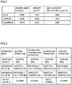
- Fig. 2 is a diagram showing the characteristics of materials used as heat storage body 5.
- Heat storage body 5 can be made using aluminum or an aluminum alloy. As compared with copper or iron, aluminum stores an amount of heat of about 70% per volume but is lightweight and inexpensive, so that aluminum is advantageous to be introduced into a product.
- Fig. 2 shows a comparison about specific heat, density and heat capacity per volume among iron, copper and aluminum.
- refrigerant circuit 10 includes a first refrigerant pipe 21, a second refrigerant pipe 22, a third refrigerant pipe 23, a fourth refrigerant pipe 24, a fifth refrigerant pipe 25, a bypass path 11, and a first on-off valve 41.
- First refrigerant pipe 21 extends from indoor heat exchanger 3 through first expansion valve 4a, heat storage body 5 and second expansion valve 4b to outdoor heat exchanger 6.
- Second refrigerant pipe 22 connects four-way valve 2 and indoor heat exchanger 3.
- Third refrigerant pipe 23 connects four-way valve 2 and outdoor heat exchanger 6.
- Fourth refrigerant pipe 24 connects a suction port of compressor 1 and four-way valve 2.
- Fifth refrigerant pipe 25 connects a discharge port of compressor 1 and four-way valve 2.
- First refrigerant pipe 21 includes a first portion, a second portion, a third portion, and a fourth portion.
- the first portion (pipes 31 and 32) extends from indoor heat exchanger 3 to first expansion valve 4a.
- the second portion (a pipe 33) extends from first expansion valve 4a to heat storage body 5.
- the third portion (a pipe 34) extends from heat storage body 5 to second expansion valve 4b.
- the fourth portion (a pipe 35) extends from second expansion valve 4b to outdoor heat exchanger 6.
- Bypass path 11 branches off from the portion between indoor heat exchanger 3 and first expansion valves 4a in first refrigerant pipe 21. Then, bypass path 11 is connected to fourth refrigerant pipe 24.
- the first portion of first refrigerant pipe 21 includes: a section connected via pipe 31 from indoor heat exchanger 3 to bypass path 11; and a section connected via pipe 32 from bypass path 11 to first expansion valve 4a.
- First on-off valve 41 is provided in bypass path 11.
- bypass path 11 and first on-off valve 41 are disposed in outdoor unit 50.
- a controller 100 may be disposed in any of outdoor unit 50 and indoor unit 51 or may be disposed separately from outdoor unit 50 and indoor unit 51.
- Four-way valve 2 is configured to be capable of bringing the communication state inside four-way valve 2 into the "first state” and the "second state".
- the “first state” indicates the state inside four-way valve 2, in which the discharge port of compressor 1 is in communication with second refrigerant pipe 22 connected to indoor heat exchanger 3 while the suction port of compressor 1 is in communication with third refrigerant pipe 23 connected to outdoor heat exchanger 6. Since this first state is employed mainly during heating, the first state is also referred to as a "heating side”.
- the “second state” indicates the state inside four-way valve 2, in which the discharge port of compressor 1 is in communication with third refrigerant pipe 23 while the suction port of compressor 1 is in communication with second refrigerant pipe 22. Since this second state is employed mainly during cooling, it is also referred to as a "cooling side".
- Controller 100 controls refrigeration cycle apparatus 101 in four operation modes.
- Fig. 3 is a diagram showing the controlled state of each of the four-way valve, the expansion valves and the on-off valve in four operation modes.
- four operation modes include a heating operation mode, a defrosting preparation operation mode, a defrosting operation mode, and a cooling operation mode.
- the present embodiment is characterized in that the defrosting preparation operation mode is interposed when the heating operation mode is shifted to the defrosting operation mode.
- Four-way valve 2 is set in the first state (on the heating side) in the heating operation, and set in the second state (on the cooling side) in the defrosting operation. Also, four-way valve 2 is set in the first state (on the heating side) in the defrosting preparation operation and set in the second state (on the cooling side) in the cooling operation.
- On-off valve 41 is set in a closed state in the heating operation and set in a fully opened state in the defrosting operation. Also, on-off valve 41 is set in a closed state in each of the defrosting preparation operation and the cooling operation.
- expansion valve 4a is throttle-controlled while expansion valve 4b is preferably controlled to be fully opened.
- expansion valve 4a is preferably controlled to be fully opened while expansion valve 4b is throttle-controlled.
- expansion valve 4a and expansion valve 4b each are throttle-controlled.
- expansion valve 4a is preferably controlled to be fully opened while expansion valve 4b is throttle-controlled.
- controller 100 is configured to: when the heating operation is shifted to the defrosting operation, perform the defrosting preparation operation in such a manner that the degree of opening of first expansion valve 4a is increased to be greater than that in the heating operation (to be fully opened from the throttle-controlled state), and the degree of opening of second expansion valve 4b is reduced to be smaller than that in the heating operation (to be brought into a throttle-controlled state from the fully opened state); and to open first on-off valve 41 in the defrosting operation.
- the flow of the refrigerant in each operation mode will be described in greater detail.
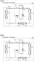
- Fig. 4 is a diagram showing the flow of refrigerant in a heating operation. Refrigerant flows sequentially through compressor 1, four-way valve 2, indoor heat exchanger 3, expansion valve 4a, heat storage body 5, expansion valve 4b, and outdoor heat exchanger 6, and then again flows through four-way valve 2, and arrives at compressor 1.
- controller 100 switches four-way valve 2 such that the discharge side of compressor 1 is in communication with indoor heat exchanger 3 while the suction side of compressor 1 is in communication with outdoor heat exchanger 6, as shown in Fig. 4 .
- the vapor refrigerant that is raised in temperature and pressure in compressor 1 passes through four-way valve 2 and flows into indoor heat exchanger 3.
- Indoor heat exchanger 3 functions as a condenser at this time.
- High-temperature and high-pressure vapor refrigerant releases heat to the indoor air introduced into indoor heat exchanger 3 by an indoor blower (not shown). Thereby, the vapor refrigerant condenses into high-pressure liquid refrigerant.
- High-pressure liquid refrigerant flows through expansion valve 4a, and thereby expands and turns into gas-liquid two-phase refrigerant of low-temperature and low-pressure, which then flows into heat storage body 5.
- heat storage body 5 After a prescribed time period has elapsed since the start of the heating operation, heat storage body 5 is in temperature equilibrium with the refrigerant flowing through the heat storage body. Thus, no heat is transmitted and received between heat storage body 5 and the refrigerant. Then, the refrigerant flows into expansion valve 4b.
- expansion valve 4b is basically set to the maximum degree of opening such that the pressure loss before and behind expansion valve 4b is minimized.
- the refrigerant having passed through expansion valve 4b flows into outdoor heat exchanger 6.
- Outdoor heat exchanger 6 functions as an evaporator at this time.
- the gas-liquid two-phase refrigerant of low-temperature and low-pressure absorbs heat from the outdoor air introduced into outdoor heat exchanger 6 by an outdoor blower (not shown). Thereby, the gas-liquid two-phase refrigerant evaporates and turns into low-pressure vapor refrigerant. Then, the low-pressure vapor refrigerant is suctioned into compressor 1 through four-way valve 2.
- the refrigerant subsequently circulates through a refrigeration cycle in the same manner as described above.
- Fig. 5 is a diagram showing the flow of refrigerant in the cooling operation.
- controller 100 switches four-way valve 2 such that the discharge side of compressor 1 is in communication with outdoor heat exchanger 6 while the suction side of compressor 1 is in communication with indoor heat exchanger 3, as shown in Fig. 5 .
- the vapor refrigerant raised in temperature and pressure in compressor 1 passes through four-way valve 2 and flows into outdoor heat exchanger 6.
- Outdoor heat exchanger 6 functions as a condenser at this time. High-temperature and high-pressure vapor refrigerant releases heat to the outdoor air introduced into outdoor heat exchanger 6 by an outdoor blower (not shown). Thereby, the vapor refrigerant condenses into high-pressure liquid refrigerant.
- expansion valve 4b The high-pressure liquid refrigerant passes through expansion valve 4b, and thereby expands and turns into gas-liquid two-phase refrigerant of low-temperature and low-pressure, which then flows into heat storage body 5.
- heat storage body 5 After a prescribed time period has elapsed since the start of the cooling operation, heat storage body 5 is in temperature equilibrium with the refrigerant flowing through the heat storage body. Thus, no heat is transmitted and received between the heat storage body and the refrigerant. Then, the refrigerant flows into expansion valve 4a.
- expansion valve 4a is basically set to the maximum degree of opening such that the pressure loss before and behind expansion valve 4a is minimized.
- the refrigerant having passed through expansion valve 4a flows into indoor heat exchanger 3.
- Indoor heat exchanger 3 functions as an evaporator at this time.
- the gas-liquid two-phase refrigerant of low-temperature and low-pressure absorbs heat from the indoor air introduced into indoor heat exchanger 3 by an indoor blower (not shown). Thereby, the gas-liquid two-phase refrigerant evaporates and turns into low-pressure vapor refrigerant. Then, the low-pressure vapor refrigerant is suctioned into compressor 1 through four-way valve 2.
- the refrigerant subsequently circulates through a refrigeration cycle in the same manner as described above.
- an amount of heat stored in heat storage body 5 is utilized in the defrosting operation in order to shorten the defrosting time and to shorten the starting up time of the heating operation.
- controller 100 determines that the defrosting operation needs to be performed.
- the high-temperature and high-pressure refrigerant discharged from compressor 1 flows into outdoor heat exchanger 6, melts the frost formed on outdoor heat exchanger 6, releases heat, and then condenses into low-temperature liquid refrigerant, which then passes sequentially through the refrigerant circuit and flows into indoor heat exchanger 3.
- the indoor blower stops blowing air in order to prevent cold air from blowing into the room.
- the refrigerant is not sufficiently evaporated and is suctioned into compressor 1 while being kept in the two-phase state.
- the liquid refrigerant is poorly evaporated and thereby suctioned into compressor 1.
- the lubricating oil is reduced in viscosity, which may lead to poor lubrication.
- compressor 1 suctions the refrigerant kept in the two-phase state
- the temperature of the refrigerant discharged from compressor 1 is lowered, thereby lowering the temperature of the refrigerant supplied to outdoor heat exchanger 6 during the defrosting operation.
- This deteriorates the defrosting performance, thereby also causing a problem that the defrosting operation time is lengthened.
- the defrosting preparation operation is performed before the heating operation is shifted to the defrosting operation.
- the defrosting preparation operation In the defrosting preparation operation, the refrigerant flows in the same direction as that in the heating operation state shown in Fig. 4 . However, the defrosting preparation operation is different from the heating operation in that the degree of opening of expansion valve 4a is greater than that during the heating operation, and in that the degree of opening of expansion valve 4b is smaller than that during the heating operation.
- This operation raises the pressure of the refrigerant passing through heat storage body 5 and also raises the refrigerant saturation temperature, so that heat can be stored in heat storage body 5.
- the temperature of the refrigerant flowing out of indoor heat exchanger 3 during the heating operation is about 40°C.
- heat storage body 5 can store heat up to 40°C.
- the defrosting preparation operation may be started when pressure Ps of the refrigerant suctioned into compressor 1, the temperature of the refrigerant suctioned into compressor 1, or the temperature of the refrigerant at the outlet of outdoor heat exchanger 6 becomes equal to or less than a prescribed value during the heating operation, or may be started after a prescribed time period of the heating operation has elapsed (for example, 60 minutes).
- the defrosting preparation operation may be started, for example, when the indoor temperature reaches a target temperature during the heating operation.
- the target temperature used herein means an indoor temperature set value of the refrigeration cycle apparatus that is set by a user.
- the defrosting preparation operation may be ended when it is determined that heat is sufficiently stored in heat storage body 5 since the difference between the measured temperature of heat storage body 5 and the temperature of indoor heat exchanger 3 becomes equal to or less than a prescribed value, or may be ended after a prescribed time period of the defrosting preparation operation has elapsed (for example, after 5 minutes).
- the defrosting preparation operation may be continued until it is determined that outdoor heat exchanger 6 needs to be defrosted.
- the above-mentioned condition for ending the defrosting preparation operation does not have to be set, but the defrosting preparation operation may be continued until defrosting is started.
- the defrosting operation is performed after the defrosting preparation operation except for the case where a user issues a command to stop the operation, the case where abnormal stop occurs in terms of refrigeration cycle control, and the like.
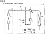
- Fig. 6 is a diagram showing the flow of refrigerant in a defrosting operation.
- four-way valve 2 is switched such that the discharge side of compressor 1 is in communication with outdoor heat exchanger 6 while the suction side of compressor 1 is in communication with indoor heat exchanger 3, and on-off valve 41 is brought into an opened state.
- the vapor refrigerant that is raised in temperature and pressure by compressor 1 passes through four-way valve 2 and flows into outdoor heat exchanger 6.
- Outdoor heat exchanger 6 functions as a condenser at this time.
- the high-temperature and high-pressure vapor refrigerant melts the frost on outdoor heat exchanger 6, thereby releasing heat and condensing into low-temperature liquid refrigerant.
- the outdoor blower (not shown) is generally not operated during the defrosting operation.
- the low-temperature liquid refrigerant having an amount of heat used for defrosting passes through expansion valve 4b and arrives at heat storage body 5.
- Heat storage body 5 stores heat during the defrosting preparation operation and the temperature of heat storage body 5 becomes high.
- heat storage body 5 functions as an evaporator.
- the low-temperature liquid refrigerant evaporates and turns into vapor refrigerant.
- the vapor refrigerant flowing out of heat storage body 5 passes through expansion valve 4a, then passes through bypass path 11 and on-off valve 41, and is suctioned into compressor 1. During the defrosting operation, the refrigerant subsequently circulates through a refrigeration cycle in the same manner as described above.
- the refrigerant circuit extending from expansion valve 4a through indoor heat exchanger 3 and four-way valve 2 to compressor 1 is longer in pipe and greater in pressure loss than bypass path 11.
- the refrigerant hardly flows through this refrigerant circuit even though the circuit is not closed by a valve or the like during the defrosting operation.
- the degree of opening of expansion valve 4a and the degree of opening of expansion valve 4b each are greater as much as possible during the defrosting operation. This is because, as the pressure loss in each of expansion valves 4a and 4b is smaller, the density of the refrigerant suctioned into compressor 1 is greater, and the amount of the circulating refrigerant is larger, with the result that the defrosting time is shortened.
- the minimum differential pressure required for operations may be set for compressor 1.
- the temperature of the refrigerant discharged from compressor 1 may rise to a value equal to or higher than a predetermined protection value (for example, 120°C).
- a predetermined protection value for example, 120°C
- the amount of heat released from heat storage body 5 needs to be temporarily reduced to lower the temperature of the refrigerant suctioned into compressor 1 to an appropriate temperature.
- the degree of opening of expansion valve 4a and increasing the degree of opening of expansion valve 4b the temperature of the refrigerant passing through heat storage body 5 can be raised.
- the temperature difference between heat storage body 5 and the refrigerant passing through heat storage body 5 is reduced. Accordingly, the amount of heat received by the refrigerant from heat storage body 5 is reduced.
- the temperature of the refrigerant suctioned into compressor 1 can be lowered to an appropriate value.
- heat storage body 5 is disposed on the refrigerant circuit between expansion valves 4a and 4b each having an adjustable degree of opening.
- the pressure and the temperature of the refrigerant passing through heat storage body 5 can be arbitrarily controlled. Accordingly, since the amount of heat transmitted and received between heat storage body 5 and the refrigerant can be controlled, the defrosting operation can be immediately performed, and the compressor can be operated within an appropriate operation range.
- the defrosting operation may be ended when the measured temperature of the pipe through which refrigerant flows out of outdoor heat exchanger 6 becomes equal to or higher than a prescribed temperature (for example, equal to or higher than 5°C), or may be ended after a prescribed time period has elapsed since the start of the defrosting operation (for example, after 5 minutes).
- a prescribed temperature for example, equal to or higher than 5°C
- the pressure loss of the refrigerant occurring in expansion valve 4a is greater than the pressure loss of the refrigerant occurring in expansion valve 4b. Accordingly, the pressure of the refrigerant passing through heat storage body 5 is reduced, and heat storage body 5 functions as an evaporator.
- heat storage body 5 when, even after heat storage body 5 is utilized as a defrosting heat source, the temperature of heat storage body 5 is higher than the outdoor air temperature and heat storage body 5 can be utilized as a heat source for the heating operation, the increasing rate of the temperature of air blown out of indoor unit 51 can be accelerated in the heating operation.
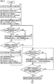
- Fig. 7 is a flowchart (first half) for illustrating an example of control for switching an operation performed by controller 100.
- Fig. 8 is a flowchart (latter half) for illustrating an example of control for switching an operation performed by controller 100.
- controller 100 In response to the command to start the heating operation from a user's remote controller and the like, controller 100 starts the process in the flowchart shown in Fig. 7 (S1). In step S2, controller 100 sets four-way valve 2 to establish connection such that the discharge port of compressor 1 is in communication with indoor heat exchanger 3 while the suction port of compressor 1 is in communication with outdoor heat exchanger 6.
- controller 100 controls expansion valve 4b to be fully opened and controls expansion valve 4a to be set to the initial degree of opening.
- indoor heat exchanger 3 functions as a condenser.
- the expansion valve is generally controlled based on the degree of subcooling (SC) of the indoor heat exchanger.
- SC subcooling
- subcooling control is performed in steps S4 to S7 by adjusting the degree of opening of expansion valve 4a.
- controller 100 determines whether or not a degree of subcooling SC of indoor heat exchanger 3 is equal to or less than a determination value SC1 (a first value SC1). In this case, controller 100 calculates the degree of subcooling SC of the refrigerant in indoor heat exchanger 3 in the following manner. First, controller 100 obtains a pressure value of a pressure sensor HS1 on the refrigerant discharge side of compressor 1, and calculates a refrigerant saturation temperature Tdsat corresponding to this pressure value. Then, controller 100 obtains a temperature value Tco of a thermistor THco disposed at the outlet portion of indoor heat exchanger 3. Controller 100 defines the difference between two temperatures (Tdsat - Tco) as the degree of subcooling SC.
- controller 100 When SC ⁇ SC1 is satisfied in step S4 (YES in S4), controller 100 reduces the degree of opening of expansion valve 4a in step S5. When SC ⁇ SC1 is not satisfied (NO in S4), controller 100 increases the degree of opening of expansion valve 4a in step S6.
- step S7 controller 100 determines whether or not pressure Ps of the refrigerant suctioned into compressor 1 is equal to or less than determination pressure Ps1.
- pressure Ps of the refrigerant suctioned into compressor 1 is derived from the pressure value of a pressure sensor LS1 disposed at the suction port of compressor 1.
- any condition may be employed from among the following three determination conditions including: 1) a temperature Ts of refrigerant suctioned into compressor 1 ⁇ a determination temperature Ts1; 2) a temperature Teo of refrigerant at the outlet of outdoor heat exchanger 6 ⁇ a determination temperature Teo1; and 3) heating operation time ⁇ determination time M1.
- temperature Ts of the suctioned refrigerant can be the temperature value of a thermistor THs installed in the suction pipe of compressor 1.
- temperature Teo of refrigerant at the outlet of outdoor heat exchanger 6 can be the temperature value of a thermistor THeo installed in the outlet pipe of outdoor heat exchanger 6.
- step S7 When the determination condition is not satisfied in step S7 (NO in S7), the process subsequent to step S4 is performed again. On the other hand, when the determination condition is satisfied in step S7 (YES in S7), the process proceeds to step S8, in which the defrosting preparation operation is started.
- controller 100 controls expansion valve 4a to be fully opened and controls expansion valve 4b to be set to the initial degree of opening (for example, to the degree of opening of expansion valve 4a during the heating operation).
- the expansion valve is controlled based on the degree of subcooling (SC) of the indoor heat exchanger in the same manner as in the heating operation.
- SC subcooling
- subcooling control is performed in steps S10 to S13 by adjusting the degree of opening of expansion valve 4b.
- controller 100 determines whether or not the degree of subcooling SC of indoor heat exchanger 3 is equal to or less than determination value SC1. Since the method of calculation the degree of subcooling SC is the same as that in step S4, the description thereof will not be repeated.
- controller 100 When SC ⁇ SC1 is satisfied in step S10 (YES in S10), controller 100 reduces the degree of opening of expansion valve 4b in step S 11. When SC ⁇ SC1 is not satisfied in step S10 (NO in S10), controller 100 increases the degree of opening of expansion valve 4b in step S12.
- step S11 or S12 is followed by the process in step S13.
- controller 100 determines whether or not a temperature Tb of heat storage body 5 is equal to or higher than a determination temperature Tb1, or whether or not the defrosting preparation operation time is equal to or longer than determination time M2.
- Temperature Tb of heat storage body 5 can be the temperature value of a thermistor THb attached to heat storage body 5.
- step S13 When the determination condition is not satisfied in step S13 (NO in S13), the process subsequent to step S10 is performed again. On the other hand, when the determination condition is satisfied in step S13 (YES in S13), the process proceeds to step S14, in which the defrosting preparation operation is ended.
- controller 100 determines whether or not pressure Ps of the refrigerant suctioned into compressor 1 is equal to or less than a second determination pressure value Ps2.
- any condition may be employed from among the following two determination conditions including: 1) temperature Ts of refrigerant suctioned into compressor 1 ⁇ a second determination temperature Ts2; and 2) a temperature Teo of refrigerant at the outlet of outdoor heat exchanger 6 ⁇ a second determination temperature Teo2.
- the defrosting operation may be started immediately after the defrosting preparation operation is ended.
- step S15 Until the determination condition in step S15 is satisfied, the defrosting operation is not started, but the heating operation is performed in the state where heat is stored in heat storage body 5 (NO in S15).
- step S16 the defrosting operation is started.
- controller 100 sets four-way valve 2 to establish connection such that the discharge port of compressor 1 is in communication with outdoor heat exchanger 6 while the suction port of compressor 1 is in communication with indoor heat exchanger 3. Furthermore, in step S18, controller 100 opens on-off valve 41 provided in bypass path 11.
- controller 100 controls expansion valve 4a and expansion valve 4b to be fully opened.
- indoor heat exchanger 3 functions as an evaporator.
- controller 100 adjusts the degree of opening of each of expansion valve 4a and expansion valve 4b, thereby adjusting the amount of heat released from heat storage body 5.
- controller 100 obtains pressure Ps of the refrigerant suctioned into compressor 1 based on the pressure value of pressure sensor LS1, and obtains pressure Pd of the refrigerant discharged from compressor 1 based on the pressure value of pressure sensor HS1. Then, a refrigerant compression ratio Pd/Ps is calculated, and it is determined whether or not this refrigerant compression ratio is equal to or less than a determination value R1.
- controller 100 When Pd/Ps ⁇ R1 is satisfied in step S20 (YES in S20), controller 100 reduces the degree of opening of expansion valve 4b in step S21. When Pd/Ps ⁇ R1 is not satisfied in step S20 (NO in S20), controller 100 increases the degree of opening of expansion valve 4b in step S22. The process in step S21 or S22 is followed by the process in step S23.
- controller 100 obtains a temperature Td of refrigerant discharged from compressor 1 based on the detection value of a temperature sensor THd. Then, controller 100 determines whether or not temperature Td of refrigerant discharged from compressor 1 is equal to or higher than a determination temperature Td1.
- step S24 controller 100 reduces the degree of opening of expansion valve 4a and increases the degree of opening of expansion valve 4b.
- Td ⁇ Td1 is satisfied, excessive heat is released from heat storage body 5. Accordingly, the degree of opening of expansion valve 4a is reduced to thereby reduce the amount of heat released from heat storage body 5.
- step S25 controller 100 increases the degree of opening of expansion valve 4a, and reduces the degree of opening of expansion valve 4b.
- the process in step S24 or S25 is followed by the process in step S26.
- step S26 controller 100 obtains a temperature TL in a liquid pipe of outdoor heat exchanger 6 from a thermistor THL. Controller 100 determines whether or not temperature TL is equal to or higher than a determination temperature TL1, or determines whether or not the defrosting operation time is equal to or longer than determination time M3. When each of these two conditions is not satisfied in step S26 (NO in S26), the process is returned to step S20. On the other hand, when at least one of these two conditions is satisfied in step S20 (YES in S26), controller 100 causes the process to proceed to step S27, in which on-off valve 41 is closed. Then, controller 100 ends the defrosting operation in step S28. Then, in step S29, the process is returned to the process of starting the heating operation.
- heat storage body 5 is disposed on the refrigerant circuit between expansion valves 4a and 4b each having an adjustable degree of opening, so that the pressure and the temperature of the refrigerant passing through heat storage body 5 can be arbitrarily controlled. Accordingly, since the amount of heat transmitted and received between heat storage body 5 and the refrigerant can be controlled, a defrosting operation can be immediately performed, and the compressor can be operated within an appropriate operation range.
- Fig. 9 is a refrigerant circuit diagram of a refrigeration cycle apparatus in the second embodiment.
- a refrigeration cycle apparatus 101A in addition to the configuration of refrigeration cycle apparatus 101, includes: a second on-off valve 42 provided in second refrigerant pipe 22; and a third on-off valve 43 provided in the first portion (31, 32) of first refrigerant pipe 21 so as to be located close to indoor heat exchanger 3 with respect to the branch point to bypass path 11.
- Each of second on-off valve 42 and third on-off valve 43 is opened during the heating operation and closed during the defrosting operation.
- Refrigeration cycle apparatus 101A further includes a first stop valve SV1 provided in second refrigerant pipe 22, and a second stop valve SV2 provided in the first portion (31, 32) of first refrigerant pipe 21.
- the stop valve is opened and closed by a work operator with a wrench in the case of installation or relocation of a refrigeration cycle apparatus.
- second on-off valve 42 and third on-off valve 43 each serve as a solenoid valve that can be opened and closed by a controller 100A during an operation.
- First stop valve SV1 is located close to indoor heat exchanger 3 with respect to second on-off valve 42.
- Second stop valve SV2 is located close to indoor heat exchanger 3 with respect to third on-off valve 43.
- on-off valve 42 is provided on the refrigerant circuit so as to be located between four-way valve 2 and indoor heat exchanger 3 while on-off valve 43 is provided on the refrigerant circuit so as to be located between indoor heat exchanger 3 and expansion valve 4a.
- on-off valves 42 and 43 are opened during the heating operation, the defrosting preparation operation and the cooling operation, and closed during the defrosting operation.
- the refrigerant becomes excessive during the defrosting operation, the amount of liquid refrigerant passing through heat storage body 5 during the defrosting operation is increased. Thus, this liquid refrigerant cannot be completely evaporated with the amount of heat stored in heat storage body 5, so that the liquid refrigerant may be suctioned into the compressor.
- the refrigerant existing inside indoor heat exchanger 3 and the indoor/outdoor connection pipe is sealed therein during the defrosting operation. Thereby, refrigerant can be prevented from becoming excessive in the refrigeration cycle apparatus in the defrosting operation.
- the motive power and the amount of heat used for conveying the liquid refrigerant from the outdoor unit to the indoor unit can be reduced during a shift to the heating operation.
- the increasing rate of the temperature of air blown out of the heating indoor unit can be accelerated.
- Fig. 10 is a refrigerant circuit diagram of a refrigeration cycle apparatus in the third embodiment.
- a refrigeration cycle apparatus 101B further includes an inverter module 5B for driving compressor 1 or for driving an outdoor blower 6B, inverter module 5B being disposed to be in contact with heat storage body 5.
- inverter module 5B includes: a power device such as a power MOSFET and an insulated gate bipolar transistor (IGBT) for controlling electric power; an intelligent power module (IPM) incorporating its drive circuit and a self protection circuit; and the like.
- IGBT insulated gate bipolar transistor
- a power element inside inverter module 5B generates heat in accordance with the value of the current flowing therethrough. Cooling is required such that the power element is set to be equal to or lower than a predetermined temperature (for example, equal to or lower than 120°C) in order to prevent thermal runaway.
- a predetermined temperature for example, equal to or lower than 120°C
- the saturation temperature of the refrigerant suctioned into compressor 1 is controlled to range between -20°C and -45°C during the defrosting operation.
- the refrigerant saturation temperature in outdoor heat exchanger 6 during the defrosting operation ranges from 0°C to about +5°C.
- pressure Ps of the refrigerant suctioned into compressor 1 with the maximum defrosting performance exists in the range between -20°C and -45°C in terms of the refrigerant saturation temperature, for example, in the case of refrigerant such as R32 and 410A.
- low pressure Ps of the refrigerant suctioned into compressor 1 leads to a low density of the refrigerant suctioned into compressor 1, and thus, the work of compressor 1 is decreased due to an insufficient amount of circulating refrigerant.
- high pressure Ps of the refrigerant suctioned into compressor 1 leads to a small differential pressure of the refrigerant before and behind compressor 1, and thus, the work of compressor 1 is decreased.
- an electric heater may be provided inside heat storage body 5 or in contact with heat storage body 5.
- a defrosting heat source can be assisted in the case where the amount of heat stored in heat storage body 5 is insufficient or in the case where a sufficiently large-sized heat storage body 5 cannot be provided in consideration of space and cost.
Landscapes
- Engineering & Computer Science (AREA)
- Physics & Mathematics (AREA)
- Mechanical Engineering (AREA)
- Thermal Sciences (AREA)
- General Engineering & Computer Science (AREA)
- Air Conditioning Control Device (AREA)
- Fluid Mechanics (AREA)
- Compression-Type Refrigeration Machines With Reversible Cycles (AREA)
Abstract
Description
- The present invention relates to a refrigeration cycle apparatus, and particularly to a refrigeration cycle apparatus that performs a defrosting operation utilizing an amount of heat stored in a heat storage body for removing frost formed on an outdoor heat exchanger.
- In a refrigeration cycle apparatus using air as a heat source, when the outdoor air temperature becomes lower than a prescribed temperature (for example, 7°C) during a heating operation, the temperature in the outdoor heat exchanger becomes less than 0°C. Thus, frost forms on the outdoor heat exchanger. Formed frost blocks an air flow passage in the outdoor heat exchanger, and thereby the heating performance deteriorates. Accordingly, the defrosting operation for melting the frost has to be performed at regular time intervals.
- Conventionally, this defrosting operation has been performed using, as a heat source, an amount of heat stored in indoor air, an indoor heat exchanger, an indoor/outdoor connection pipe and a compressor by operating a refrigeration cycle apparatus while switching a four-way valve of the refrigeration cycle apparatus into a cooling side.
- However, in the above-mentioned operation system, indoor air is used as a heat source, and cold air is fed into the room that is supposed to be heated, so that the comfortableness inside the room is deteriorated. Furthermore, refrigerant is cooled by defrosting. When the refrigerant flows through the indoor heat exchanger, the indoor/outdoor connection pipe and the compressor, the refrigerant removes heat from these components. Accordingly, when the defrosting operation is ended and the heating operation is resumed, the above-mentioned components have to be heated again, which delays the increasing rate of the temperature of warm air blowing into the room.
- For this reason, according to the technique disclosed in Japanese Patent Laying-Open No.
2009-287903 - PTL 1: Japanese Patent Laying-Open No.
2009-287903 Fig. 1 ) - However, in the configuration of the heat storage body disclosed in the above-mentioned Japanese Patent Laying-Open No.
2009-287903 - Specifically, when the pressure of the refrigerant flowing through a heat storage body during the defrosting operation is unnecessarily small, the temperature of the refrigerant flowing through the heat storage body falls. Thus, the amount of heat is transferred more than necessary from the heat storage body to the refrigerant, so that the temperature of the refrigerant suctioned into the compressor excessively rises. This also causes a problem that the temperature of the refrigerant discharged from the compressor is raised accordingly to be equal to or higher than a protection value (for example, 120°C). Furthermore, when the pressure of the refrigerant flowing through the heat storage body during the defrosting operation is unnecessarily high, the amount of heat transferred from the heat storage body to the refrigerant is reduced. Thus, the liquid refrigerant cannot be completely evaporated and suctioned into the compressor. Then, lubricating oil inside the compressor is diluted with the refrigerant and reduced in viscosity. This also causes a problem that lubrication is poor in a compression mechanism.
- The present invention has been made to solve the above-described problems. An object of the present invention is to provide a refrigeration cycle apparatus characterized by shortening a defrosting time and accelerating recovery of the heating performance after the heating operation is resumed.
- The present disclosure relates to a refrigeration cycle apparatus. The refrigeration cycle apparatus includes: a refrigerant circuit through which refrigerant circulates in a forward direction or an opposite direction to the forward direction sequentially through a compressor, an indoor heat exchanger, a first expansion valve, a heat storage body, a second expansion valve, and an outdoor heat exchanger, and back to the compressor; and a four-way valve configured to change a circulation direction of the refrigerant. The refrigerant circuit includes a first refrigerant pipe, a second refrigerant pipe, a third refrigerant pipe, a fourth refrigerant pipe, a fifth refrigerant pipe, a bypass path, and a first on-off valve. The first refrigerant pipe extends from the outdoor heat exchanger through the first expansion valve, the heat storage body and the second expansion valve to the indoor heat exchanger. The second refrigerant pipe connects the four-way valve and the indoor heat exchanger. The third refrigerant pipe connects the four-way valve and the outdoor heat exchanger. The fourth refrigerant pipe connects a suction port of the compressor and the four-way valve. The fifth refrigerant pipe connects a discharge port of the compressor and the four-way valve. The bypass path branches off from a first portion in the first refrigerant pipe and leads to the fourth refrigerant pipe, and the first portion connects the indoor heat exchanger and the first expansion valve. The first on-off valve is provided in the bypass path.
- According to the present invention, a heat storage body is disposed on a refrigerant circuit, which connects an indoor heat exchanger and an outdoor heat exchanger, so as to be located between two expansion valves each having an adjustable degree of opening and provided on the refrigerant circuit. By the configuration as described above, heat of the refrigerant is stored in a heat storage body in a defrosting preparation operation, and heat is released from the heat storage body to the refrigerant in a defrosting operation, so as to be capable of implementing a defrosting heat source. In this case, as the pressure of refrigerant flowing through the heat storage body is adjusted by two expansion valves, the amount of heat exchanged between the heat storage body and the refrigerant can be adjusted. Thereby, an appropriate operation state of the refrigeration cycle apparatus can be maintained.
-
-
Fig. 1 is a refrigerant circuit diagram of a refrigeration cycle apparatus in the first embodiment. -
Fig. 2 is a diagram showing the characteristics of materials used as aheat storage body 5. -
Fig. 3 is a diagram showing the controlled state of each of a four-way valve, expansion valves and an on-off valve in four operation modes. -
Fig. 4 is a diagram showing the flow of refrigerant in a heating operation. -
Fig. 5 is a diagram showing the flow of refrigerant in a cooling operation. -
Fig. 6 is a diagram showing the flow of refrigerant in a defrosting operation. -
Fig. 7 is a flowchart (first half) for illustrating an example of control for switching an operation. -
Fig. 8 is a flowchart (latter half) for illustrating an example of control for switching an operation. -
Fig. 9 is a refrigerant circuit diagram of a refrigeration cycle apparatus in the second embodiment. -
Fig. 10 is a refrigerant circuit diagram of a refrigeration cycle apparatus in the third embodiment. - The embodiments of the present invention will be hereinafter described in detail with reference to the accompanying drawings. In the following, while a plurality of embodiments will be described, it has been originally intended to combine the configurations described in each embodiment as appropriate. Also, the same or corresponding components in the accompanying drawings are designated by the same reference characters, and description thereof will not be repeated.
-
Fig. 1 is a refrigerant circuit diagram of a refrigeration cycle apparatus in the first embodiment. - Referring to
Fig. 1 , arefrigeration cycle apparatus 101 includes arefrigerant circuit 10 through which refrigerant circulates in a forward direction or an opposite direction to the forward direction sequentially through acompressor 1, a four-way valve 2, anindoor heat exchanger 3, afirst expansion valve 4a, aheat storage body 5, asecond expansion valve 4b, anoutdoor heat exchanger 6, and four-way valve 2, and back tocompressor 1. The circulation direction of the refrigerant is changed by four-way valve 2 provided betweencompressor 1 andindoor heat exchanger 3, and also betweencompressor 1 andoutdoor heat exchanger 6.Compressor 1, four-way valve 2,outdoor heat exchanger 6,heat storage body 5,first expansion valve 4a, andsecond expansion valve 4b are disposed in anoutdoor unit 50.Indoor heat exchanger 3 is disposed in anindoor unit 51. - In the present embodiment,
heat storage body 5 is disposed on a refrigerant circuit, which connectsindoor heat exchanger 3 andoutdoor heat exchanger 6, so as to be located between twoexpansion valves heat storage body 5 in a defrosting preparation operation, and heat is released fromheat storage body 5 to the refrigerant in a defrosting operation, and therebyheat storage body 5 is capable of implementing a defrosting heat source. As the pressure of the refrigerant flowing throughheat storage body 5 is adjusted byexpansion valves heat storage body 5 and the refrigerant can be adjusted. Thereby, an appropriate operation state of the refrigeration cycle apparatus can be maintained. -
Heat storage body 5 is disposed as a heat source during a defrosting operation.Heat storage body 5 is disposed inrefrigerant circuit 10 so as to be located on firstrefrigerant pipe 21 that connectsindoor heat exchanger 3 andoutdoor heat exchanger 6.First expansion valve 4a is disposed in firstrefrigerant pipe 21 so as to be located betweenindoor heat exchanger 3 andheat storage body 5.Second expansion valve 4b is disposed in firstrefrigerant pipe 21 so as to be located betweenoutdoor heat exchanger 6 andheat storage body 5. -
Fig. 2 is a diagram showing the characteristics of materials used asheat storage body 5.Heat storage body 5 can be made using aluminum or an aluminum alloy. As compared with copper or iron, aluminum stores an amount of heat of about 70% per volume but is lightweight and inexpensive, so that aluminum is advantageous to be introduced into a product.Fig. 2 shows a comparison about specific heat, density and heat capacity per volume among iron, copper and aluminum. - Again referring to
Fig. 1 ,refrigerant circuit 10 includes a firstrefrigerant pipe 21, a secondrefrigerant pipe 22, a thirdrefrigerant pipe 23, a fourthrefrigerant pipe 24, a fifthrefrigerant pipe 25, abypass path 11, and a first on-offvalve 41. Firstrefrigerant pipe 21 extends fromindoor heat exchanger 3 throughfirst expansion valve 4a,heat storage body 5 andsecond expansion valve 4b tooutdoor heat exchanger 6.Second refrigerant pipe 22 connects four-way valve 2 andindoor heat exchanger 3.Third refrigerant pipe 23 connects four-way valve 2 andoutdoor heat exchanger 6.Fourth refrigerant pipe 24 connects a suction port ofcompressor 1 and four-way valve 2.Fifth refrigerant pipe 25 connects a discharge port ofcompressor 1 and four-way valve 2. - First
refrigerant pipe 21 includes a first portion, a second portion, a third portion, and a fourth portion. The first portion (pipes 31 and 32) extends fromindoor heat exchanger 3 tofirst expansion valve 4a. The second portion (a pipe 33) extends fromfirst expansion valve 4a to heatstorage body 5. The third portion (a pipe 34) extends fromheat storage body 5 tosecond expansion valve 4b. The fourth portion (a pipe 35) extends fromsecond expansion valve 4b tooutdoor heat exchanger 6. Bypasspath 11 branches off from the portion betweenindoor heat exchanger 3 andfirst expansion valves 4a in firstrefrigerant pipe 21. Then, bypasspath 11 is connected to fourthrefrigerant pipe 24. The first portion of firstrefrigerant pipe 21 includes: a section connected viapipe 31 fromindoor heat exchanger 3 to bypasspath 11; and a section connected viapipe 32 frombypass path 11 tofirst expansion valve 4a. First on-offvalve 41 is provided inbypass path 11. - Four-
way valve 2,bypass path 11 and first on-offvalve 41 are disposed inoutdoor unit 50. Although not particularly limited, acontroller 100 may be disposed in any ofoutdoor unit 50 andindoor unit 51 or may be disposed separately fromoutdoor unit 50 andindoor unit 51. - Four-
way valve 2 is configured to be capable of bringing the communication state inside four-way valve 2 into the "first state" and the "second state". The "first state" indicates the state inside four-way valve 2, in which the discharge port ofcompressor 1 is in communication with secondrefrigerant pipe 22 connected toindoor heat exchanger 3 while the suction port ofcompressor 1 is in communication with thirdrefrigerant pipe 23 connected tooutdoor heat exchanger 6. Since this first state is employed mainly during heating, the first state is also referred to as a "heating side". The "second state" indicates the state inside four-way valve 2, in which the discharge port ofcompressor 1 is in communication with thirdrefrigerant pipe 23 while the suction port ofcompressor 1 is in communication with secondrefrigerant pipe 22. Since this second state is employed mainly during cooling, it is also referred to as a "cooling side". -
Controller 100 controlsrefrigeration cycle apparatus 101 in four operation modes.Fig. 3 is a diagram showing the controlled state of each of the four-way valve, the expansion valves and the on-off valve in four operation modes. - Referring to
Fig. 3 , four operation modes include a heating operation mode, a defrosting preparation operation mode, a defrosting operation mode, and a cooling operation mode. The present embodiment is characterized in that the defrosting preparation operation mode is interposed when the heating operation mode is shifted to the defrosting operation mode. - Four-
way valve 2 is set in the first state (on the heating side) in the heating operation, and set in the second state (on the cooling side) in the defrosting operation. Also, four-way valve 2 is set in the first state (on the heating side) in the defrosting preparation operation and set in the second state (on the cooling side) in the cooling operation. - On-off
valve 41 is set in a closed state in the heating operation and set in a fully opened state in the defrosting operation. Also, on-offvalve 41 is set in a closed state in each of the defrosting preparation operation and the cooling operation. - In the heating operation,
expansion valve 4a is throttle-controlled whileexpansion valve 4b is preferably controlled to be fully opened. In the defrosting preparation operation,expansion valve 4a is preferably controlled to be fully opened whileexpansion valve 4b is throttle-controlled. In the defrosting operation,expansion valve 4a andexpansion valve 4b each are throttle-controlled. In the cooling operation,expansion valve 4a is preferably controlled to be fully opened whileexpansion valve 4b is throttle-controlled. - As apparent from the above description,
controller 100 is configured to: when the heating operation is shifted to the defrosting operation, perform the defrosting preparation operation in such a manner that the degree of opening offirst expansion valve 4a is increased to be greater than that in the heating operation (to be fully opened from the throttle-controlled state), and the degree of opening ofsecond expansion valve 4b is reduced to be smaller than that in the heating operation (to be brought into a throttle-controlled state from the fully opened state); and to open first on-offvalve 41 in the defrosting operation. In the following, the flow of the refrigerant in each operation mode will be described in greater detail. -
Fig. 4 is a diagram showing the flow of refrigerant in a heating operation. Refrigerant flows sequentially throughcompressor 1, four-way valve 2,indoor heat exchanger 3,expansion valve 4a,heat storage body 5,expansion valve 4b, andoutdoor heat exchanger 6, and then again flows through four-way valve 2, and arrives atcompressor 1. - Since on-off
valve 41 is opened only in the defrosting operation, the refrigerant does not flow throughbypass path 11 in the heating operation. - In the heating operation,
controller 100 switches four-way valve 2 such that the discharge side ofcompressor 1 is in communication withindoor heat exchanger 3 while the suction side ofcompressor 1 is in communication withoutdoor heat exchanger 6, as shown inFig. 4 . The vapor refrigerant that is raised in temperature and pressure incompressor 1 passes through four-way valve 2 and flows intoindoor heat exchanger 3.Indoor heat exchanger 3 functions as a condenser at this time. High-temperature and high-pressure vapor refrigerant releases heat to the indoor air introduced intoindoor heat exchanger 3 by an indoor blower (not shown). Thereby, the vapor refrigerant condenses into high-pressure liquid refrigerant. - High-pressure liquid refrigerant flows through
expansion valve 4a, and thereby expands and turns into gas-liquid two-phase refrigerant of low-temperature and low-pressure, which then flows intoheat storage body 5. After a prescribed time period has elapsed since the start of the heating operation,heat storage body 5 is in temperature equilibrium with the refrigerant flowing through the heat storage body. Thus, no heat is transmitted and received betweenheat storage body 5 and the refrigerant. Then, the refrigerant flows intoexpansion valve 4b. In the heating operation,expansion valve 4b is basically set to the maximum degree of opening such that the pressure loss before and behindexpansion valve 4b is minimized. - The refrigerant having passed through
expansion valve 4b flows intooutdoor heat exchanger 6.Outdoor heat exchanger 6 functions as an evaporator at this time. The gas-liquid two-phase refrigerant of low-temperature and low-pressure absorbs heat from the outdoor air introduced intooutdoor heat exchanger 6 by an outdoor blower (not shown). Thereby, the gas-liquid two-phase refrigerant evaporates and turns into low-pressure vapor refrigerant. Then, the low-pressure vapor refrigerant is suctioned intocompressor 1 through four-way valve 2. The refrigerant subsequently circulates through a refrigeration cycle in the same manner as described above. -
Fig. 5 is a diagram showing the flow of refrigerant in the cooling operation. In the cooling operation,controller 100 switches four-way valve 2 such that the discharge side ofcompressor 1 is in communication withoutdoor heat exchanger 6 while the suction side ofcompressor 1 is in communication withindoor heat exchanger 3, as shown inFig. 5 . The vapor refrigerant raised in temperature and pressure incompressor 1 passes through four-way valve 2 and flows intooutdoor heat exchanger 6.Outdoor heat exchanger 6 functions as a condenser at this time. High-temperature and high-pressure vapor refrigerant releases heat to the outdoor air introduced intooutdoor heat exchanger 6 by an outdoor blower (not shown). Thereby, the vapor refrigerant condenses into high-pressure liquid refrigerant. - The high-pressure liquid refrigerant passes through
expansion valve 4b, and thereby expands and turns into gas-liquid two-phase refrigerant of low-temperature and low-pressure, which then flows intoheat storage body 5. After a prescribed time period has elapsed since the start of the cooling operation,heat storage body 5 is in temperature equilibrium with the refrigerant flowing through the heat storage body. Thus, no heat is transmitted and received between the heat storage body and the refrigerant. Then, the refrigerant flows intoexpansion valve 4a. In the cooling operation,expansion valve 4a is basically set to the maximum degree of opening such that the pressure loss before and behindexpansion valve 4a is minimized. - The refrigerant having passed through
expansion valve 4a flows intoindoor heat exchanger 3.Indoor heat exchanger 3 functions as an evaporator at this time. The gas-liquid two-phase refrigerant of low-temperature and low-pressure absorbs heat from the indoor air introduced intoindoor heat exchanger 3 by an indoor blower (not shown). Thereby, the gas-liquid two-phase refrigerant evaporates and turns into low-pressure vapor refrigerant. Then, the low-pressure vapor refrigerant is suctioned intocompressor 1 through four-way valve 2. The refrigerant subsequently circulates through a refrigeration cycle in the same manner as described above. - When the outdoor air temperature becomes lower than a prescribed temperature (for example, 7°C) in the heating operation of the refrigeration cycle apparatus, the temperature of
outdoor heat exchanger 6 becomes lower than 0°C. Then, frost forms onoutdoor heat exchanger 6. Frost formed onoutdoor heat exchanger 6 blocks an air flow passage to thereby deteriorate the heating performance. Thus, the defrosting operation for melting the frost has to be performed at regular time intervals. - However, long-continued defrosting operation deteriorates the comfortableness inside the room. Thus, in the present embodiment, an amount of heat stored in
heat storage body 5 is utilized in the defrosting operation in order to shorten the defrosting time and to shorten the starting up time of the heating operation. - For example, when frost forms on a fin of
outdoor heat exchanger 6 to serve as resistance against heat transfer or ventilation during the heating operation, pressure Ps of the refrigerant suctioned intocompressor 1, the temperature of the refrigerant suctioned intocompressor 1 or the temperature of the refrigerant at the outlet ofoutdoor heat exchanger 6 is decreased. When pressure Ps of the refrigerant suctioned intocompressor 1, the temperature of the refrigerant suctioned intocompressor 1 or the temperature of the refrigerant at the outlet ofoutdoor heat exchanger 6 becomes equal to or less than a prescribed value,controller 100 determines that the defrosting operation needs to be performed. - Conventionally, the following technique is known. Specifically, in the defrosting operation, four-
way valve 2 is switched from the heating operation side to the cooling operation side, so that the high-temperature and high-pressure vapor refrigerant discharged fromcompressor 1 is caused to flow intooutdoor heat exchanger 6, thereby melting the frost onoutdoor heat exchanger 6. - However, when four-
way valve 2 is switched from the heating side to the cooling side to perform a defrosting operation without performing a defrosting preparation operation, a failure may occur incompressor 1 due to poor lubrication. - In the defrosting operation, the high-temperature and high-pressure refrigerant discharged from
compressor 1 flows intooutdoor heat exchanger 6, melts the frost formed onoutdoor heat exchanger 6, releases heat, and then condenses into low-temperature liquid refrigerant, which then passes sequentially through the refrigerant circuit and flows intoindoor heat exchanger 3. At this time, the indoor blower stops blowing air in order to prevent cold air from blowing into the room. Thus, the refrigerant is not sufficiently evaporated and is suctioned intocompressor 1 while being kept in the two-phase state. In other words, when the defrosting preparation operation is not performed, the liquid refrigerant is poorly evaporated and thereby suctioned intocompressor 1. Thus, due to mixing with the liquid refrigerant, the lubricating oil is reduced in viscosity, which may lead to poor lubrication. - Furthermore, when
compressor 1 suctions the refrigerant kept in the two-phase state, the temperature of the refrigerant discharged fromcompressor 1 is lowered, thereby lowering the temperature of the refrigerant supplied tooutdoor heat exchanger 6 during the defrosting operation. This deteriorates the defrosting performance, thereby also causing a problem that the defrosting operation time is lengthened. - Therefore, in the present embodiment, in order to shorten the defrosting operation and to prevent the liquid refrigerant from being suctioned into the compressor during the defrosting operation, the defrosting preparation operation is performed before the heating operation is shifted to the defrosting operation.
- In the defrosting preparation operation, the refrigerant flows in the same direction as that in the heating operation state shown in
Fig. 4 . However, the defrosting preparation operation is different from the heating operation in that the degree of opening ofexpansion valve 4a is greater than that during the heating operation, and in that the degree of opening ofexpansion valve 4b is smaller than that during the heating operation. - This operation raises the pressure of the refrigerant passing through
heat storage body 5 and also raises the refrigerant saturation temperature, so that heat can be stored inheat storage body 5. The temperature of the refrigerant flowing out ofindoor heat exchanger 3 during the heating operation is about 40°C. In this case,heat storage body 5 can store heat up to 40°C. When pressure loss occurs before and behindexpansion valve 4a during the defrosting preparation operation, the temperature of the refrigerant lowers, so that the temperature of the stored heat lowers. Accordingly, it is preferable thatexpansion valve 4a is fully opened during the defrosting preparation operation. - The defrosting preparation operation may be started when pressure Ps of the refrigerant suctioned into
compressor 1, the temperature of the refrigerant suctioned intocompressor 1, or the temperature of the refrigerant at the outlet ofoutdoor heat exchanger 6 becomes equal to or less than a prescribed value during the heating operation, or may be started after a prescribed time period of the heating operation has elapsed (for example, 60 minutes). - Furthermore, when storage of heat in
heat storage body 5 is completed, andheat storage body 5 is brought into thermal equilibrium with the refrigerant flowing throughheat storage body 5, no heat is transmitted and received betweenheat storage body 5 and the refrigerant. Thereby, no influence is exerted upon the heating ability and performance. Thus, for the preparation of the defrosting operation that will be required, the defrosting preparation operation may be started, for example, when the indoor temperature reaches a target temperature during the heating operation. The target temperature used herein means an indoor temperature set value of the refrigeration cycle apparatus that is set by a user. - The defrosting preparation operation may be ended when it is determined that heat is sufficiently stored in
heat storage body 5 since the difference between the measured temperature ofheat storage body 5 and the temperature ofindoor heat exchanger 3 becomes equal to or less than a prescribed value, or may be ended after a prescribed time period of the defrosting preparation operation has elapsed (for example, after 5 minutes). - Furthermore, when storage of heat in
heat storage body 5 is completed andheat storage body 5 is brought into thermal equilibrium with the refrigerant passing throughheat storage body 5, no heat is transmitted and received between the heat storage body and the refrigerant. Thereby, no influence is exerted upon the heating ability and performance. Accordingly, the defrosting preparation operation may be continued until it is determined thatoutdoor heat exchanger 6 needs to be defrosted. In other words, the above-mentioned condition for ending the defrosting preparation operation does not have to be set, but the defrosting preparation operation may be continued until defrosting is started. - The defrosting operation is performed after the defrosting preparation operation except for the case where a user issues a command to stop the operation, the case where abnormal stop occurs in terms of refrigeration cycle control, and the like.
-
Fig. 6 is a diagram showing the flow of refrigerant in a defrosting operation. In the defrosting operation, four-way valve 2 is switched such that the discharge side ofcompressor 1 is in communication withoutdoor heat exchanger 6 while the suction side ofcompressor 1 is in communication withindoor heat exchanger 3, and on-offvalve 41 is brought into an opened state. The vapor refrigerant that is raised in temperature and pressure bycompressor 1 passes through four-way valve 2 and flows intooutdoor heat exchanger 6.Outdoor heat exchanger 6 functions as a condenser at this time. The high-temperature and high-pressure vapor refrigerant melts the frost onoutdoor heat exchanger 6, thereby releasing heat and condensing into low-temperature liquid refrigerant. - In addition, in order to allow the condensation heat of the refrigerant to be efficiently used for defrosting without being used for heating the outdoor air, the outdoor blower (not shown) is generally not operated during the defrosting operation.
- The low-temperature liquid refrigerant having an amount of heat used for defrosting passes through
expansion valve 4b and arrives atheat storage body 5.Heat storage body 5 stores heat during the defrosting preparation operation and the temperature ofheat storage body 5 becomes high. Thus,heat storage body 5 functions as an evaporator. As a result of heat exchange withheat storage body 5, the low-temperature liquid refrigerant evaporates and turns into vapor refrigerant. - The vapor refrigerant flowing out of
heat storage body 5 passes throughexpansion valve 4a, then passes throughbypass path 11 and on-offvalve 41, and is suctioned intocompressor 1. During the defrosting operation, the refrigerant subsequently circulates through a refrigeration cycle in the same manner as described above. - In addition, the refrigerant circuit extending from
expansion valve 4a throughindoor heat exchanger 3 and four-way valve 2 tocompressor 1 is longer in pipe and greater in pressure loss thanbypass path 11. Thus, the refrigerant hardly flows through this refrigerant circuit even though the circuit is not closed by a valve or the like during the defrosting operation. - It is preferable that the degree of opening of
expansion valve 4a and the degree of opening ofexpansion valve 4b each are greater as much as possible during the defrosting operation. This is because, as the pressure loss in each ofexpansion valves compressor 1 is greater, and the amount of the circulating refrigerant is larger, with the result that the defrosting time is shortened. - On the other hand, for example, in the case where a differential pressure oil supply system is employed as a lubricating oil supply system inside
compressor 1, the minimum differential pressure required for operations may be set forcompressor 1. In this case, it is preferable that notexpansion valve 4a butexpansion valve 4b is reduced in degree of opening during the defrosting operation. This is because pressure loss of the refrigerant mainly occurs on theexpansion valve 4b side, so that the temperature of the refrigerant passing throughheat storage body 5 is lowered, thereby increasing the rate and the amount of heat released fromheat storage body 5 to the refrigerant. - Furthermore, when the suction pressure of
compressor 1 is relatively low even though the temperature of the refrigerant suctioned intocompressor 1 is relatively high, the temperature of the refrigerant discharged fromcompressor 1 may rise to a value equal to or higher than a predetermined protection value (for example, 120°C). In this case, the amount of heat released fromheat storage body 5 needs to be temporarily reduced to lower the temperature of the refrigerant suctioned intocompressor 1 to an appropriate temperature. In this case, by reducing the degree of opening ofexpansion valve 4a and increasing the degree of opening ofexpansion valve 4b, the temperature of the refrigerant passing throughheat storage body 5 can be raised. In this case, the temperature difference betweenheat storage body 5 and the refrigerant passing throughheat storage body 5 is reduced. Accordingly, the amount of heat received by the refrigerant fromheat storage body 5 is reduced. Thus, the temperature of the refrigerant suctioned intocompressor 1 can be lowered to an appropriate value. - In the present embodiment,
heat storage body 5 is disposed on the refrigerant circuit betweenexpansion valves heat storage body 5 can be arbitrarily controlled. Accordingly, since the amount of heat transmitted and received betweenheat storage body 5 and the refrigerant can be controlled, the defrosting operation can be immediately performed, and the compressor can be operated within an appropriate operation range. - The defrosting operation may be ended when the measured temperature of the pipe through which refrigerant flows out of
outdoor heat exchanger 6 becomes equal to or higher than a prescribed temperature (for example, equal to or higher than 5°C), or may be ended after a prescribed time period has elapsed since the start of the defrosting operation (for example, after 5 minutes). - When the defrosting operation is shifted to the heating operation, four-
way valve 2 is switched from the cooling side to the heating side while on-offvalve 41 is closed, as shown inFig. 4 . Also, the degree of opening ofexpansion valve 4a is reduced whileexpansion valve 4b is preferably fully opened. - In this case, the pressure loss of the refrigerant occurring in
expansion valve 4a is greater than the pressure loss of the refrigerant occurring inexpansion valve 4b. Accordingly, the pressure of the refrigerant passing throughheat storage body 5 is reduced, andheat storage body 5 functions as an evaporator. - Therefore, when, even after
heat storage body 5 is utilized as a defrosting heat source, the temperature ofheat storage body 5 is higher than the outdoor air temperature andheat storage body 5 can be utilized as a heat source for the heating operation, the increasing rate of the temperature of air blown out ofindoor unit 51 can be accelerated in the heating operation. -
Fig. 7 is a flowchart (first half) for illustrating an example of control for switching an operation performed bycontroller 100.Fig. 8 is a flowchart (latter half) for illustrating an example of control for switching an operation performed bycontroller 100. - In response to the command to start the heating operation from a user's remote controller and the like,
controller 100 starts the process in the flowchart shown inFig. 7 (S1). In step S2,controller 100 sets four-way valve 2 to establish connection such that the discharge port ofcompressor 1 is in communication withindoor heat exchanger 3 while the suction port ofcompressor 1 is in communication withoutdoor heat exchanger 6. - Then, in step S3,
controller 100 controlsexpansion valve 4b to be fully opened and controlsexpansion valve 4a to be set to the initial degree of opening. When the refrigerant is circulated bycompressor 1,indoor heat exchanger 3 functions as a condenser. - In the heating operation, the expansion valve is generally controlled based on the degree of subcooling (SC) of the indoor heat exchanger. In the present embodiment, subcooling control is performed in steps S4 to S7 by adjusting the degree of opening of
expansion valve 4a. - In step S4,
controller 100 determines whether or not a degree of subcooling SC ofindoor heat exchanger 3 is equal to or less than a determination value SC1 (a first value SC1). In this case,controller 100 calculates the degree of subcooling SC of the refrigerant inindoor heat exchanger 3 in the following manner. First,controller 100 obtains a pressure value of a pressure sensor HS1 on the refrigerant discharge side ofcompressor 1, and calculates a refrigerant saturation temperature Tdsat corresponding to this pressure value. Then,controller 100 obtains a temperature value Tco of a thermistor THco disposed at the outlet portion ofindoor heat exchanger 3.Controller 100 defines the difference between two temperatures (Tdsat - Tco) as the degree of subcooling SC. - When SC ≤ SC1 is satisfied in step S4 (YES in S4),
controller 100 reduces the degree of opening ofexpansion valve 4a in step S5. When SC ≤ SC1 is not satisfied (NO in S4),controller 100 increases the degree of opening ofexpansion valve 4a in step S6. - The process in step S4 or S5 is followed by the process in step S7. In step S7,
controller 100 determines whether or not pressure Ps of the refrigerant suctioned intocompressor 1 is equal to or less than determination pressure Ps1. In this case, pressure Ps of the refrigerant suctioned intocompressor 1 is derived from the pressure value of a pressure sensor LS1 disposed at the suction port ofcompressor 1. - In place of the determination in step S7, any condition may be employed from among the following three determination conditions including: 1) a temperature Ts of refrigerant suctioned into
compressor 1 ≤ a determination temperature Ts1; 2) a temperature Teo of refrigerant at the outlet ofoutdoor heat exchanger 6 ≤ a determination temperature Teo1; and 3) heating operation time ≥ determination time M1. In this case, temperature Ts of the suctioned refrigerant can be the temperature value of a thermistor THs installed in the suction pipe ofcompressor 1. Furthermore, temperature Teo of refrigerant at the outlet ofoutdoor heat exchanger 6 can be the temperature value of a thermistor THeo installed in the outlet pipe ofoutdoor heat exchanger 6. - When the determination condition is not satisfied in step S7 (NO in S7), the process subsequent to step S4 is performed again. On the other hand, when the determination condition is satisfied in step S7 (YES in S7), the process proceeds to step S8, in which the defrosting preparation operation is started.
- When the defrosting preparation operation is started, first in step S9,
controller 100 controlsexpansion valve 4a to be fully opened and controlsexpansion valve 4b to be set to the initial degree of opening (for example, to the degree of opening ofexpansion valve 4a during the heating operation). - Also in the defrosting preparation operation, the expansion valve is controlled based on the degree of subcooling (SC) of the indoor heat exchanger in the same manner as in the heating operation. In the defrosting preparation operation, subcooling control is performed in steps S10 to S13 by adjusting the degree of opening of
expansion valve 4b. - In step S10,
controller 100 determines whether or not the degree of subcooling SC ofindoor heat exchanger 3 is equal to or less than determination value SC1. Since the method of calculation the degree of subcooling SC is the same as that in step S4, the description thereof will not be repeated. - When SC ≤ SC1 is satisfied in step S10 (YES in S10),
controller 100 reduces the degree of opening ofexpansion valve 4b instep S 11. When SC ≤ SC1 is not satisfied in step S10 (NO in S10),controller 100 increases the degree of opening ofexpansion valve 4b in step S12. - The process in step S11 or S12 is followed by the process in step S13. In step S13,
controller 100 determines whether or not a temperature Tb ofheat storage body 5 is equal to or higher than a determination temperature Tb1, or whether or not the defrosting preparation operation time is equal to or longer than determination time M2. Temperature Tb ofheat storage body 5 can be the temperature value of a thermistor THb attached toheat storage body 5. - When the determination condition is not satisfied in step S13 (NO in S13), the process subsequent to step S10 is performed again. On the other hand, when the determination condition is satisfied in step S13 (YES in S13), the process proceeds to step S14, in which the defrosting preparation operation is ended.
- Then, referring to
Fig. 8 , in step S15,controller 100 determines whether or not pressure Ps of the refrigerant suctioned intocompressor 1 is equal to or less than a second determination pressure value Ps2. - In place of the determination in step S15, any condition may be employed from among the following two determination conditions including: 1) temperature Ts of refrigerant suctioned into
compressor 1 ≤ a second determination temperature Ts2; and 2) a temperature Teo of refrigerant at the outlet ofoutdoor heat exchanger 6 ≤ a second determination temperature Teo2. Also, the defrosting operation may be started immediately after the defrosting preparation operation is ended. - Until the determination condition in step S15 is satisfied, the defrosting operation is not started, but the heating operation is performed in the state where heat is stored in heat storage body 5 (NO in S15). When the determination condition is satisfied in step S15, the process proceeds to step S16, in which the defrosting operation is started.
- In step S17,
controller 100 sets four-way valve 2 to establish connection such that the discharge port ofcompressor 1 is in communication withoutdoor heat exchanger 6 while the suction port ofcompressor 1 is in communication withindoor heat exchanger 3. Furthermore, in step S18,controller 100 opens on-offvalve 41 provided inbypass path 11. - Then, in step S19,
controller 100 controlsexpansion valve 4a andexpansion valve 4b to be fully opened. When the refrigerant is circulated bycompressor 1,indoor heat exchanger 3 functions as an evaporator. - In the defrosting operation, in the following steps S20 to S25,
controller 100 adjusts the degree of opening of each ofexpansion valve 4a andexpansion valve 4b, thereby adjusting the amount of heat released fromheat storage body 5. - First in step S20,
controller 100 obtains pressure Ps of the refrigerant suctioned intocompressor 1 based on the pressure value of pressure sensor LS1, and obtains pressure Pd of the refrigerant discharged fromcompressor 1 based on the pressure value of pressure sensor HS1. Then, a refrigerant compression ratio Pd/Ps is calculated, and it is determined whether or not this refrigerant compression ratio is equal to or less than a determination value R1. - When Pd/Ps ≤ R1 is satisfied in step S20 (YES in S20),
controller 100 reduces the degree of opening ofexpansion valve 4b in step S21. When Pd/Ps ≤ R1 is not satisfied in step S20 (NO in S20),controller 100 increases the degree of opening ofexpansion valve 4b in step S22. The process in step S21 or S22 is followed by the process in step S23. - In step S23,
controller 100 obtains a temperature Td of refrigerant discharged fromcompressor 1 based on the detection value of a temperature sensor THd. Then,controller 100 determines whether or not temperature Td of refrigerant discharged fromcompressor 1 is equal to or higher than a determination temperature Td1. - When Td ≥ Td1 is satisfied in step S23 (YES in S23), then in step S24,
controller 100 reduces the degree of opening ofexpansion valve 4a and increases the degree of opening ofexpansion valve 4b. When Td ≥ Td1 is satisfied, excessive heat is released fromheat storage body 5. Accordingly, the degree of opening ofexpansion valve 4a is reduced to thereby reduce the amount of heat released fromheat storage body 5. - On the other hand, when Td ≥ Td1 is not satisfied in step S23 (NO in S23), then in step S25,
controller 100 increases the degree of opening ofexpansion valve 4a, and reduces the degree of opening ofexpansion valve 4b. The process in step S24 or S25 is followed by the process in step S26. - In step S26,
controller 100 obtains a temperature TL in a liquid pipe ofoutdoor heat exchanger 6 from a thermistor THL.Controller 100 determines whether or not temperature TL is equal to or higher than a determination temperature TL1, or determines whether or not the defrosting operation time is equal to or longer than determination time M3. When each of these two conditions is not satisfied in step S26 (NO in S26), the process is returned to step S20. On the other hand, when at least one of these two conditions is satisfied in step S20 (YES in S26),controller 100 causes the process to proceed to step S27, in which on-offvalve 41 is closed. Then,controller 100 ends the defrosting operation in step S28. Then, in step S29, the process is returned to the process of starting the heating operation. - As described above, in the present embodiment,
heat storage body 5 is disposed on the refrigerant circuit betweenexpansion valves heat storage body 5 can be arbitrarily controlled. Accordingly, since the amount of heat transmitted and received betweenheat storage body 5 and the refrigerant can be controlled, a defrosting operation can be immediately performed, and the compressor can be operated within an appropriate operation range. -
Fig. 9 is a refrigerant circuit diagram of a refrigeration cycle apparatus in the second embodiment. As shown inFig. 9 , in addition to the configuration ofrefrigeration cycle apparatus 101, arefrigeration cycle apparatus 101A includes: a second on-offvalve 42 provided in secondrefrigerant pipe 22; and a third on-offvalve 43 provided in the first portion (31, 32) of firstrefrigerant pipe 21 so as to be located close toindoor heat exchanger 3 with respect to the branch point to bypasspath 11. Each of second on-offvalve 42 and third on-offvalve 43 is opened during the heating operation and closed during the defrosting operation. -
Refrigeration cycle apparatus 101A further includes a first stop valve SV1 provided in secondrefrigerant pipe 22, and a second stop valve SV2 provided in the first portion (31, 32) of firstrefrigerant pipe 21. The stop valve is opened and closed by a work operator with a wrench in the case of installation or relocation of a refrigeration cycle apparatus. In contrast, second on-offvalve 42 and third on-offvalve 43 each serve as a solenoid valve that can be opened and closed by acontroller 100A during an operation. First stop valve SV1 is located close toindoor heat exchanger 3 with respect to second on-offvalve 42. Second stop valve SV2 is located close toindoor heat exchanger 3 with respect to third on-offvalve 43. - In other words, in the present embodiment, on-off
valve 42 is provided on the refrigerant circuit so as to be located between four-way valve 2 andindoor heat exchanger 3 while on-offvalve 43 is provided on the refrigerant circuit so as to be located betweenindoor heat exchanger 3 andexpansion valve 4a. In the present embodiment, on-offvalves - When the refrigerant becomes excessive during the defrosting operation, the amount of liquid refrigerant passing through
heat storage body 5 during the defrosting operation is increased. Thus, this liquid refrigerant cannot be completely evaporated with the amount of heat stored inheat storage body 5, so that the liquid refrigerant may be suctioned into the compressor. In the second embodiment, the refrigerant existing insideindoor heat exchanger 3 and the indoor/outdoor connection pipe is sealed therein during the defrosting operation. Thereby, refrigerant can be prevented from becoming excessive in the refrigeration cycle apparatus in the defrosting operation. - Furthermore, by sealing the refrigerant in the indoor heat exchanger during the defrosting operation, the motive power and the amount of heat used for conveying the liquid refrigerant from the outdoor unit to the indoor unit can be reduced during a shift to the heating operation. Thus, the increasing rate of the temperature of air blown out of the heating indoor unit can be accelerated.
-
Fig. 10 is a refrigerant circuit diagram of a refrigeration cycle apparatus in the third embodiment. As shown inFig. 10 , in addition to the configuration ofrefrigeration cycle apparatus 101 in the first embodiment, arefrigeration cycle apparatus 101B further includes aninverter module 5B for drivingcompressor 1 or for driving anoutdoor blower 6B,inverter module 5B being disposed to be in contact withheat storage body 5. For example,inverter module 5B includes: a power device such as a power MOSFET and an insulated gate bipolar transistor (IGBT) for controlling electric power; an intelligent power module (IPM) incorporating its drive circuit and a self protection circuit; and the like. - A power element inside
inverter module 5B generates heat in accordance with the value of the current flowing therethrough. Cooling is required such that the power element is set to be equal to or lower than a predetermined temperature (for example, equal to or lower than 120°C) in order to prevent thermal runaway. By bringinginverter module 5B into contact withheat storage body 5, heat generated from the inverter element can be utilized as a defrosting heat source during the defrosting operation while coolinginverter module 5B. - In the above-described first to third embodiments, it is preferable that the saturation temperature of the refrigerant suctioned into
compressor 1 is controlled to range between -20°C and -45°C during the defrosting operation. When the amount of heat stored inheat storage body 5 is exhausted, only the work of compressing the refrigerant bycompressor 1 serves as a defrosting heat source. The refrigerant saturation temperature inoutdoor heat exchanger 6 during the defrosting operation ranges from 0°C to about +5°C. In this case, pressure Ps of the refrigerant suctioned intocompressor 1 with the maximum defrosting performance exists in the range between -20°C and -45°C in terms of the refrigerant saturation temperature, for example, in the case of refrigerant such as R32 and 410A. This results from the following reasons. Specifically, low pressure Ps of the refrigerant suctioned intocompressor 1 leads to a low density of the refrigerant suctioned intocompressor 1, and thus, the work ofcompressor 1 is decreased due to an insufficient amount of circulating refrigerant. Also, high pressure Ps of the refrigerant suctioned intocompressor 1 leads to a small differential pressure of the refrigerant before and behindcompressor 1, and thus, the work ofcompressor 1 is decreased. - Furthermore, in the above-described first to third embodiments, an electric heater may be provided inside
heat storage body 5 or in contact withheat storage body 5. Thereby, a defrosting heat source can be assisted in the case where the amount of heat stored inheat storage body 5 is insufficient or in the case where a sufficiently large-sizedheat storage body 5 cannot be provided in consideration of space and cost. - It should be understood that the embodiments disclosed herein are illustrative and non-restrictive in every respect. The scope of the present invention is defined by the terms of the claims, rather than the description above, and is intended to include any modifications within the meaning and scope equivalent to the terms of the claims.
- 1 compressor, 2 four-way valve, 3 indoor heat exchanger, 4a, 4b expansion valve, 5 heat storage body, 5B inverter module, 6 outdoor heat exchanger, 6B outdoor blower, 10 refrigerant circuit, 11 bypass path, 21 to 24 refrigerant pipe, 41 to 43 on-off valve, 50 outdoor unit, 51 indoor unit, 100 controller, 101, 101A, 101B refrigeration cycle apparatus, HS1, LS1 pressure sensor, SV1 first stop valve, SV2 second stop valve, THL, THb, THco, THeo, THs thermistor, THd temperature sensor.
Claims (10)
- A refrigeration cycle apparatus comprising a refrigerant circuit through which refrigerant circulates in a forward direction or an opposite direction to the forward direction sequentially through a compressor, a four-way valve, an indoor heat exchanger, a first expansion valve, a heat storage body, a second expansion valve, and an outdoor heat exchanger, and the four-way valve, and back to the compressor,
the refrigerant circuit comprisinga first refrigerant pipe extending from the indoor heat exchanger through the first expansion valve, the heat storage body and the second expansion valve to the outdoor heat exchanger,a second refrigerant pipe connecting the four-way valve and the indoor heat exchanger,a third refrigerant pipe connecting the four-way valve and the outdoor heat exchanger,a fourth refrigerant pipe connecting a suction port of the compressor and the four-way valve,a bypass path branching off from a first portion in the first refrigerant pipe and leading to the fourth refrigerant pipe, the first portion connecting the indoor heat exchanger and the first expansion valve, anda first on-off valve provided in the bypass path. - The refrigeration cycle apparatus according to claim 1, wherein
the four-way valve is configured tocause the refrigerant to circulate in the forward direction in a heating operation andcause the refrigerant to circulate in the opposite direction in a defrosting operation,when the heating operation is shifted to the defrosting operation, a defrosting preparation operation is performed in such a manner that, while the first on-off valve is kept closed, a degree of opening of the first expansion valve is increased to be larger than that in the heating operation, and a degree of opening of the second expansion valve is reduced to be smaller than that in the heating operation, and
the first on-off valve is opened in the defrosting operation. - The refrigeration cycle apparatus according to claim 2, wherein
the defrosting preparation operation is startedwhen one of pressure of refrigerant suctioned into the compressor, a temperature of refrigerant suctioned into the compressor, and a temperature of refrigerant at an outlet of the outdoor heat exchanger becomes smaller than a first value during the heating operation, orwhen a prescribed time period passes since start of the heating operation. - The refrigeration cycle apparatus according to claim 2, wherein during the heating operation, the defrosting preparation operation is started when an indoor temperature reaches a set value set by a user.
- The refrigeration cycle apparatus according to claim 2, wherein
the defrosting preparation operation is endedwhen a temperature difference between the heat storage body and the indoor heat exchanger becomes smaller than a first value during the defrosting preparation operation, orwhen a prescribed time period passes since start of the defrosting preparation operation. - The refrigeration cycle apparatus according to claim 2, wherein the defrosting preparation operation is continued until the defrosting operation is started.
- The refrigeration cycle apparatus according to claim 2, wherein
the four-way valve is configured to switch a communication state inside the four-way valve between a first state and a second state, to allow a circulation direction of the refrigerant to be changed,
in the first state,a discharge port of the compressor is in communication with the second refrigerant pipe, anda suction port of the compressor is in communication with the third refrigerant pipe, andin the second state,the discharge port of the compressor is in communication with the third refrigerant pipe, andthe suction port of the compressor is in communication with the second refrigerant pipe. - The refrigeration cycle apparatus according to claim 2, further comprising:a second on-off valve provided in the second refrigerant pipe; anda third on-off valve provided in the first portion of the first refrigerant pipe so as to be located close to the indoor heat exchanger with respect to a branch point to the bypass path, whereineach of the second on-off valve and the third on-off valve is opened during the heating operation and closed during the defrosting operation.
- The refrigeration cycle apparatus according to claim 8, further comprising:a first stop valve provided in the second refrigerant pipe; anda second stop valve provided in the first portion of the first refrigerant pipe, whereinthe first stop valve is located close to the indoor heat exchanger with respect to the second on-off valve, andthe second stop valve is located close to the indoor heat exchanger with respect to the third on-off valve.
- The refrigeration cycle apparatus according to claim 1, further comprising an inverter module for driving the compressor or for driving an outdoor blower, the inverter module being disposed to be in contact with the heat storage body.
Applications Claiming Priority (1)
| Application Number | Priority Date | Filing Date | Title |
|---|---|---|---|
| PCT/JP2017/016776 WO2018198275A1 (en) | 2017-04-27 | 2017-04-27 | Refrigeration cycle device |
Publications (3)
| Publication Number | Publication Date |
|---|---|
| EP3617616A1 true EP3617616A1 (en) | 2020-03-04 |
| EP3617616A4 EP3617616A4 (en) | 2020-03-04 |
| EP3617616B1 EP3617616B1 (en) | 2023-11-15 |
Family
ID=63919600
Family Applications (1)
| Application Number | Title | Priority Date | Filing Date |
|---|---|---|---|
| EP17907530.4A Active EP3617616B1 (en) | 2017-04-27 | 2017-04-27 | Refrigeration cycle device |
Country Status (5)
| Country | Link |
|---|---|
| US (1) | US11175082B2 (en) |
| EP (1) | EP3617616B1 (en) |
| JP (1) | JP6771661B2 (en) |
| ES (1) | ES2966139T3 (en) |
| WO (1) | WO2018198275A1 (en) |
Families Citing this family (12)
| Publication number | Priority date | Publication date | Assignee | Title |
|---|---|---|---|---|
| WO2019159721A1 (en) * | 2018-02-19 | 2019-08-22 | ダイキン工業株式会社 | Air-conditioning apparatus |
| US10907879B2 (en) * | 2018-12-31 | 2021-02-02 | Thermo King Corporation | Methods and systems for energy efficient defrost of a transport climate control system evaporator |
| JP7331021B2 (en) * | 2019-02-06 | 2023-08-22 | 三菱電機株式会社 | refrigeration cycle equipment |
| WO2020174684A1 (en) * | 2019-02-28 | 2020-09-03 | 三菱電機株式会社 | Refrigeration cycle device |
| DE102019212503A1 (en) * | 2019-08-21 | 2021-02-25 | Audi Ag | Method for operating a refrigeration system for a vehicle with a refrigerant circuit that can be operated for a refrigeration system operation |
| US11976840B2 (en) * | 2021-01-11 | 2024-05-07 | Rheem Manufacturing Company | Devices and systems for air conditioning units having a subcooling line |
| CN116263263A (en) * | 2021-12-13 | 2023-06-16 | 开利公司 | Method for changing defrosting trigger of heat pump |
| US11959690B2 (en) | 2021-12-17 | 2024-04-16 | Trane International Inc. | Thermal storage device for climate control system |
| CN115183402B (en) * | 2022-07-04 | 2024-05-14 | 青岛海尔空调电子有限公司 | Control method and control device for defrosting of air conditioner and air conditioner |
| US12529489B2 (en) * | 2022-07-11 | 2026-01-20 | Rheem Manufacturing Company | Enhanced heat pump defrost without use of auxiliary heat |
| JP7647831B1 (en) | 2023-09-29 | 2025-03-18 | 株式会社富士通ゼネラル | Refrigeration cycle device and method for controlling the refrigeration cycle device |
| WO2025224965A1 (en) * | 2024-04-26 | 2025-10-30 | 三菱電機株式会社 | Refrigeration cycle device |
Family Cites Families (14)
| Publication number | Priority date | Publication date | Assignee | Title |
|---|---|---|---|---|
| AT380560B (en) * | 1984-09-04 | 1986-06-10 | Neura Electronics Tech Anlagen | METHOD AND DEVICE FOR DEFROSTING EVAPORATORS IN HEAT PUMP AND COLD MACHINE SYSTEMS |
| JPH0652142B2 (en) | 1986-05-16 | 1994-07-06 | 三洋電機株式会社 | Air conditioner |
| JP2902853B2 (en) * | 1992-04-27 | 1999-06-07 | 三洋電機株式会社 | Air conditioner |
| JPH1123036A (en) * | 1997-07-04 | 1999-01-26 | Fujitsu General Ltd | Air conditioner |
| JP4974714B2 (en) * | 2007-03-09 | 2012-07-11 | 三菱電機株式会社 | Water heater |
| JP2009287903A (en) * | 2008-06-02 | 2009-12-10 | Kansai Electric Power Co Inc:The | Thermal storage type heat pump device |
| JP5287820B2 (en) * | 2010-10-14 | 2013-09-11 | パナソニック株式会社 | Air conditioner |
| JP5370453B2 (en) * | 2011-09-30 | 2013-12-18 | ダイキン工業株式会社 | Automotive temperature control system |
| KR101873597B1 (en) * | 2012-02-23 | 2018-07-31 | 엘지전자 주식회사 | An air conditioner |
| EP2636548B1 (en) * | 2012-03-05 | 2017-09-06 | Hanon Systems | Heat pump system for vehicle |
| JP2013245850A (en) * | 2012-05-24 | 2013-12-09 | Hitachi Appliances Inc | Air conditioner |
| DE102012222594B4 (en) * | 2012-12-10 | 2018-05-17 | Bayerische Motoren Werke Aktiengesellschaft | Method for operating a refrigerant circuit as a heat pump and as a heat pump operable refrigerant circuit |
| JP5977885B2 (en) * | 2013-04-26 | 2016-08-24 | 東芝キヤリア株式会社 | Water heater |
| JP6286675B2 (en) | 2015-02-20 | 2018-03-07 | パナソニックIpマネジメント株式会社 | Air conditioner |
-
2017
- 2017-04-27 WO PCT/JP2017/016776 patent/WO2018198275A1/en not_active Ceased
- 2017-04-27 EP EP17907530.4A patent/EP3617616B1/en active Active
- 2017-04-27 JP JP2019514988A patent/JP6771661B2/en not_active Expired - Fee Related
- 2017-04-27 ES ES17907530T patent/ES2966139T3/en active Active
- 2017-04-27 US US16/496,076 patent/US11175082B2/en active Active
Also Published As
| Publication number | Publication date |
|---|---|
| US11175082B2 (en) | 2021-11-16 |
| ES2966139T3 (en) | 2024-04-18 |
| EP3617616B1 (en) | 2023-11-15 |
| JPWO2018198275A1 (en) | 2020-02-20 |
| WO2018198275A1 (en) | 2018-11-01 |
| JP6771661B2 (en) | 2020-10-21 |
| US20200049392A1 (en) | 2020-02-13 |
| EP3617616A4 (en) | 2020-03-04 |
Similar Documents
| Publication | Publication Date | Title |
|---|---|---|
| EP3617616B1 (en) | Refrigeration cycle device | |
| US10077924B2 (en) | Binary refrigeration apparatus | |
| EP3054239B1 (en) | Air conditioner | |
| US20130192280A1 (en) | Refrigerator and defrosting method thereof | |
| EP3361184B1 (en) | Refrigeration cycle device | |
| KR101155497B1 (en) | Heat pump type speed heating apparatus | |
| US9719708B2 (en) | Air-conditioning apparatus with simultaneous heating and cooling operation | |
| JP2002107014A (en) | Air conditioner | |
| US10753658B2 (en) | Air-conditioning apparatus | |
| WO2019224945A1 (en) | Refrigeration cycle apparatus | |
| CN113348333B (en) | Outdoor unit of refrigerating device and refrigerating device including the outdoor unit | |
| JP2015064169A (en) | Hot water generator | |
| JP2012167860A (en) | Heat pump type air conditioner and defrosting method of the same | |
| JP2014181866A (en) | Air conditioner | |
| US10443913B2 (en) | Refrigerator and method for controlling the same | |
| US20070074523A1 (en) | Refrigerating apparatus | |
| CN113970212A (en) | Refrigerator and refrigerator defrosting method | |
| EP3696478A1 (en) | Heat pump system | |
| KR102342448B1 (en) | Heat pump | |
| KR102494571B1 (en) | Heat pump | |
| JPWO2020161834A1 (en) | Refrigeration cycle equipment | |
| KR101212686B1 (en) | Heat pump type speed heating apparatus | |
| CN115111871A (en) | Refrigerating and freezing device and defrosting control method thereof | |
| KR20220006334A (en) | Air conditioner and control method thereof | |
| EP3816545A1 (en) | Refrigeration cycle device and liquid heating device comprising same |
Legal Events
| Date | Code | Title | Description |
|---|---|---|---|
| STAA | Information on the status of an ep patent application or granted ep patent |
Free format text: STATUS: THE INTERNATIONAL PUBLICATION HAS BEEN MADE |
|
| PUAI | Public reference made under article 153(3) epc to a published international application that has entered the european phase |
Free format text: ORIGINAL CODE: 0009012 |
|
| STAA | Information on the status of an ep patent application or granted ep patent |
Free format text: STATUS: REQUEST FOR EXAMINATION WAS MADE |
|
| 17P | Request for examination filed |
Effective date: 20191021 |
|
| A4 | Supplementary search report drawn up and despatched |
Effective date: 20200204 |
|
| AK | Designated contracting states |
Kind code of ref document: A1 Designated state(s): AL AT BE BG CH CY CZ DE DK EE ES FI FR GB GR HR HU IE IS IT LI LT LU LV MC MK MT NL NO PL PT RO RS SE SI SK SM TR |
|
| AX | Request for extension of the european patent |
Extension state: BA ME |
|
| DAV | Request for validation of the european patent (deleted) | ||
| DAX | Request for extension of the european patent (deleted) | ||
| STAA | Information on the status of an ep patent application or granted ep patent |
Free format text: STATUS: EXAMINATION IS IN PROGRESS |
|
| 17Q | First examination report despatched |
Effective date: 20220513 |
|
| REG | Reference to a national code |
Ref country code: DE Ref legal event code: R079 Free format text: PREVIOUS MAIN CLASS: F25B0047020000 Ipc: F25B0041390000 Ref country code: DE Ref legal event code: R079 Ref document number: 602017076639 Country of ref document: DE Free format text: PREVIOUS MAIN CLASS: F25B0047020000 Ipc: F25B0041390000 |
|
| RIC1 | Information provided on ipc code assigned before grant |
Ipc: B60H 1/22 20060101ALI20230426BHEP Ipc: F25B 13/00 20060101ALI20230426BHEP Ipc: F25B 47/02 20060101ALI20230426BHEP Ipc: F25B 49/02 20060101ALI20230426BHEP Ipc: F25B 41/39 20210101AFI20230426BHEP |
|
| GRAP | Despatch of communication of intention to grant a patent |
Free format text: ORIGINAL CODE: EPIDOSNIGR1 |
|
| STAA | Information on the status of an ep patent application or granted ep patent |
Free format text: STATUS: GRANT OF PATENT IS INTENDED |
|
| INTG | Intention to grant announced |
Effective date: 20230605 |
|
| GRAS | Grant fee paid |
Free format text: ORIGINAL CODE: EPIDOSNIGR3 |
|
| GRAA | (expected) grant |
Free format text: ORIGINAL CODE: 0009210 |
|
| STAA | Information on the status of an ep patent application or granted ep patent |
Free format text: STATUS: THE PATENT HAS BEEN GRANTED |
|
| AK | Designated contracting states |
Kind code of ref document: B1 Designated state(s): AL AT BE BG CH CY CZ DE DK EE ES FI FR GB GR HR HU IE IS IT LI LT LU LV MC MK MT NL NO PL PT RO RS SE SI SK SM TR |
|
| REG | Reference to a national code |
Ref country code: CH Ref legal event code: EP Ref country code: GB Ref legal event code: FG4D |
|
| P01 | Opt-out of the competence of the unified patent court (upc) registered |
Effective date: 20231018 |
|
| REG | Reference to a national code |
Ref country code: DE Ref legal event code: R096 Ref document number: 602017076639 Country of ref document: DE |
|
| REG | Reference to a national code |
Ref country code: IE Ref legal event code: FG4D |
|
| REG | Reference to a national code |
Ref country code: SE Ref legal event code: TRGR |
|
| REG | Reference to a national code |
Ref country code: LT Ref legal event code: MG9D |
|
| REG | Reference to a national code |
Ref country code: NL Ref legal event code: MP Effective date: 20231115 |
|
| PG25 | Lapsed in a contracting state [announced via postgrant information from national office to epo] |
Ref country code: GR Free format text: LAPSE BECAUSE OF FAILURE TO SUBMIT A TRANSLATION OF THE DESCRIPTION OR TO PAY THE FEE WITHIN THE PRESCRIBED TIME-LIMIT Effective date: 20240216 |
|
| PG25 | Lapsed in a contracting state [announced via postgrant information from national office to epo] |
Ref country code: IS Free format text: LAPSE BECAUSE OF FAILURE TO SUBMIT A TRANSLATION OF THE DESCRIPTION OR TO PAY THE FEE WITHIN THE PRESCRIBED TIME-LIMIT Effective date: 20240315 |
|
| PG25 | Lapsed in a contracting state [announced via postgrant information from national office to epo] |
Ref country code: LT Free format text: LAPSE BECAUSE OF FAILURE TO SUBMIT A TRANSLATION OF THE DESCRIPTION OR TO PAY THE FEE WITHIN THE PRESCRIBED TIME-LIMIT Effective date: 20231115 |
|
| REG | Reference to a national code |
Ref country code: AT Ref legal event code: MK05 Ref document number: 1632111 Country of ref document: AT Kind code of ref document: T Effective date: 20231115 |
|
| PG25 | Lapsed in a contracting state [announced via postgrant information from national office to epo] |
Ref country code: NL Free format text: LAPSE BECAUSE OF FAILURE TO SUBMIT A TRANSLATION OF THE DESCRIPTION OR TO PAY THE FEE WITHIN THE PRESCRIBED TIME-LIMIT Effective date: 20231115 |
|
| REG | Reference to a national code |
Ref country code: ES Ref legal event code: FG2A Ref document number: 2966139 Country of ref document: ES Kind code of ref document: T3 Effective date: 20240418 |
|
| PG25 | Lapsed in a contracting state [announced via postgrant information from national office to epo] |
Ref country code: AT Free format text: LAPSE BECAUSE OF FAILURE TO SUBMIT A TRANSLATION OF THE DESCRIPTION OR TO PAY THE FEE WITHIN THE PRESCRIBED TIME-LIMIT Effective date: 20231115 |
|
| PG25 | Lapsed in a contracting state [announced via postgrant information from national office to epo] |
Ref country code: NL Free format text: LAPSE BECAUSE OF FAILURE TO SUBMIT A TRANSLATION OF THE DESCRIPTION OR TO PAY THE FEE WITHIN THE PRESCRIBED TIME-LIMIT Effective date: 20231115 Ref country code: LT Free format text: LAPSE BECAUSE OF FAILURE TO SUBMIT A TRANSLATION OF THE DESCRIPTION OR TO PAY THE FEE WITHIN THE PRESCRIBED TIME-LIMIT Effective date: 20231115 Ref country code: IS Free format text: LAPSE BECAUSE OF FAILURE TO SUBMIT A TRANSLATION OF THE DESCRIPTION OR TO PAY THE FEE WITHIN THE PRESCRIBED TIME-LIMIT Effective date: 20240315 Ref country code: GR Free format text: LAPSE BECAUSE OF FAILURE TO SUBMIT A TRANSLATION OF THE DESCRIPTION OR TO PAY THE FEE WITHIN THE PRESCRIBED TIME-LIMIT Effective date: 20240216 Ref country code: BG Free format text: LAPSE BECAUSE OF FAILURE TO SUBMIT A TRANSLATION OF THE DESCRIPTION OR TO PAY THE FEE WITHIN THE PRESCRIBED TIME-LIMIT Effective date: 20240215 Ref country code: AT Free format text: LAPSE BECAUSE OF FAILURE TO SUBMIT A TRANSLATION OF THE DESCRIPTION OR TO PAY THE FEE WITHIN THE PRESCRIBED TIME-LIMIT Effective date: 20231115 Ref country code: PT Free format text: LAPSE BECAUSE OF FAILURE TO SUBMIT A TRANSLATION OF THE DESCRIPTION OR TO PAY THE FEE WITHIN THE PRESCRIBED TIME-LIMIT Effective date: 20240315 |
|
| PGFP | Annual fee paid to national office [announced via postgrant information from national office to epo] |
Ref country code: GB Payment date: 20240307 Year of fee payment: 8 |
|
| PG25 | Lapsed in a contracting state [announced via postgrant information from national office to epo] |
Ref country code: RS Free format text: LAPSE BECAUSE OF FAILURE TO SUBMIT A TRANSLATION OF THE DESCRIPTION OR TO PAY THE FEE WITHIN THE PRESCRIBED TIME-LIMIT Effective date: 20231115 Ref country code: PL Free format text: LAPSE BECAUSE OF FAILURE TO SUBMIT A TRANSLATION OF THE DESCRIPTION OR TO PAY THE FEE WITHIN THE PRESCRIBED TIME-LIMIT Effective date: 20231115 Ref country code: NO Free format text: LAPSE BECAUSE OF FAILURE TO SUBMIT A TRANSLATION OF THE DESCRIPTION OR TO PAY THE FEE WITHIN THE PRESCRIBED TIME-LIMIT Effective date: 20240215 Ref country code: LV Free format text: LAPSE BECAUSE OF FAILURE TO SUBMIT A TRANSLATION OF THE DESCRIPTION OR TO PAY THE FEE WITHIN THE PRESCRIBED TIME-LIMIT Effective date: 20231115 Ref country code: HR Free format text: LAPSE BECAUSE OF FAILURE TO SUBMIT A TRANSLATION OF THE DESCRIPTION OR TO PAY THE FEE WITHIN THE PRESCRIBED TIME-LIMIT Effective date: 20231115 |
|
| PGFP | Annual fee paid to national office [announced via postgrant information from national office to epo] |
Ref country code: TR Payment date: 20240328 Year of fee payment: 8 Ref country code: SE Payment date: 20240312 Year of fee payment: 8 Ref country code: IT Payment date: 20240313 Year of fee payment: 8 Ref country code: FR Payment date: 20240308 Year of fee payment: 8 |
|
| PG25 | Lapsed in a contracting state [announced via postgrant information from national office to epo] |
Ref country code: DK Free format text: LAPSE BECAUSE OF FAILURE TO SUBMIT A TRANSLATION OF THE DESCRIPTION OR TO PAY THE FEE WITHIN THE PRESCRIBED TIME-LIMIT Effective date: 20231115 |
|
| PGFP | Annual fee paid to national office [announced via postgrant information from national office to epo] |
Ref country code: ES Payment date: 20240507 Year of fee payment: 8 |
|
| PG25 | Lapsed in a contracting state [announced via postgrant information from national office to epo] |
Ref country code: CZ Free format text: LAPSE BECAUSE OF FAILURE TO SUBMIT A TRANSLATION OF THE DESCRIPTION OR TO PAY THE FEE WITHIN THE PRESCRIBED TIME-LIMIT Effective date: 20231115 |
|
| PG25 | Lapsed in a contracting state [announced via postgrant information from national office to epo] |
Ref country code: SK Free format text: LAPSE BECAUSE OF FAILURE TO SUBMIT A TRANSLATION OF THE DESCRIPTION OR TO PAY THE FEE WITHIN THE PRESCRIBED TIME-LIMIT Effective date: 20231115 |
|
| PG25 | Lapsed in a contracting state [announced via postgrant information from national office to epo] |
Ref country code: SM Free format text: LAPSE BECAUSE OF FAILURE TO SUBMIT A TRANSLATION OF THE DESCRIPTION OR TO PAY THE FEE WITHIN THE PRESCRIBED TIME-LIMIT Effective date: 20231115 Ref country code: SK Free format text: LAPSE BECAUSE OF FAILURE TO SUBMIT A TRANSLATION OF THE DESCRIPTION OR TO PAY THE FEE WITHIN THE PRESCRIBED TIME-LIMIT Effective date: 20231115 Ref country code: RO Free format text: LAPSE BECAUSE OF FAILURE TO SUBMIT A TRANSLATION OF THE DESCRIPTION OR TO PAY THE FEE WITHIN THE PRESCRIBED TIME-LIMIT Effective date: 20231115 Ref country code: EE Free format text: LAPSE BECAUSE OF FAILURE TO SUBMIT A TRANSLATION OF THE DESCRIPTION OR TO PAY THE FEE WITHIN THE PRESCRIBED TIME-LIMIT Effective date: 20231115 Ref country code: DK Free format text: LAPSE BECAUSE OF FAILURE TO SUBMIT A TRANSLATION OF THE DESCRIPTION OR TO PAY THE FEE WITHIN THE PRESCRIBED TIME-LIMIT Effective date: 20231115 Ref country code: CZ Free format text: LAPSE BECAUSE OF FAILURE TO SUBMIT A TRANSLATION OF THE DESCRIPTION OR TO PAY THE FEE WITHIN THE PRESCRIBED TIME-LIMIT Effective date: 20231115 |
|
| REG | Reference to a national code |
Ref country code: DE Ref legal event code: R097 Ref document number: 602017076639 Country of ref document: DE |
|
| PLBE | No opposition filed within time limit |
Free format text: ORIGINAL CODE: 0009261 |
|
| STAA | Information on the status of an ep patent application or granted ep patent |
Free format text: STATUS: NO OPPOSITION FILED WITHIN TIME LIMIT |
|
| 26N | No opposition filed |
Effective date: 20240819 |
|
| PG25 | Lapsed in a contracting state [announced via postgrant information from national office to epo] |
Ref country code: SI Free format text: LAPSE BECAUSE OF FAILURE TO SUBMIT A TRANSLATION OF THE DESCRIPTION OR TO PAY THE FEE WITHIN THE PRESCRIBED TIME-LIMIT Effective date: 20231115 |
|
| PG25 | Lapsed in a contracting state [announced via postgrant information from national office to epo] |
Ref country code: SI Free format text: LAPSE BECAUSE OF FAILURE TO SUBMIT A TRANSLATION OF THE DESCRIPTION OR TO PAY THE FEE WITHIN THE PRESCRIBED TIME-LIMIT Effective date: 20231115 |
|
| PG25 | Lapsed in a contracting state [announced via postgrant information from national office to epo] |
Ref country code: MC Free format text: LAPSE BECAUSE OF FAILURE TO SUBMIT A TRANSLATION OF THE DESCRIPTION OR TO PAY THE FEE WITHIN THE PRESCRIBED TIME-LIMIT Effective date: 20231115 |
|
| PG25 | Lapsed in a contracting state [announced via postgrant information from national office to epo] |
Ref country code: MC Free format text: LAPSE BECAUSE OF FAILURE TO SUBMIT A TRANSLATION OF THE DESCRIPTION OR TO PAY THE FEE WITHIN THE PRESCRIBED TIME-LIMIT Effective date: 20231115 |
|
| REG | Reference to a national code |
Ref country code: CH Ref legal event code: PL |
|
| PG25 | Lapsed in a contracting state [announced via postgrant information from national office to epo] |
Ref country code: LU Free format text: LAPSE BECAUSE OF NON-PAYMENT OF DUE FEES Effective date: 20240427 |
|
| REG | Reference to a national code |
Ref country code: BE Ref legal event code: MM Effective date: 20240430 |
|
| PG25 | Lapsed in a contracting state [announced via postgrant information from national office to epo] |
Ref country code: LU Free format text: LAPSE BECAUSE OF NON-PAYMENT OF DUE FEES Effective date: 20240427 |
|
| PG25 | Lapsed in a contracting state [announced via postgrant information from national office to epo] |
Ref country code: BE Free format text: LAPSE BECAUSE OF NON-PAYMENT OF DUE FEES Effective date: 20240430 |
|
| PG25 | Lapsed in a contracting state [announced via postgrant information from national office to epo] |
Ref country code: BE Free format text: LAPSE BECAUSE OF NON-PAYMENT OF DUE FEES Effective date: 20240430 Ref country code: CH Free format text: LAPSE BECAUSE OF NON-PAYMENT OF DUE FEES Effective date: 20240430 |
|
| PG25 | Lapsed in a contracting state [announced via postgrant information from national office to epo] |
Ref country code: IE Free format text: LAPSE BECAUSE OF NON-PAYMENT OF DUE FEES Effective date: 20240427 |
|
| PGFP | Annual fee paid to national office [announced via postgrant information from national office to epo] |
Ref country code: DE Payment date: 20250305 Year of fee payment: 9 |
|
| PG25 | Lapsed in a contracting state [announced via postgrant information from national office to epo] |
Ref country code: CY Free format text: LAPSE BECAUSE OF FAILURE TO SUBMIT A TRANSLATION OF THE DESCRIPTION OR TO PAY THE FEE WITHIN THE PRESCRIBED TIME-LIMIT; INVALID AB INITIO Effective date: 20170427 |
|
| PG25 | Lapsed in a contracting state [announced via postgrant information from national office to epo] |
Ref country code: HU Free format text: LAPSE BECAUSE OF FAILURE TO SUBMIT A TRANSLATION OF THE DESCRIPTION OR TO PAY THE FEE WITHIN THE PRESCRIBED TIME-LIMIT; INVALID AB INITIO Effective date: 20170427 |
|
| PG25 | Lapsed in a contracting state [announced via postgrant information from national office to epo] |
Ref country code: FI Free format text: LAPSE BECAUSE OF FAILURE TO SUBMIT A TRANSLATION OF THE DESCRIPTION OR TO PAY THE FEE WITHIN THE PRESCRIBED TIME-LIMIT Effective date: 20231115 |
|
| REG | Reference to a national code |
Ref country code: SE Ref legal event code: EUG |
|
| GBPC | Gb: european patent ceased through non-payment of renewal fee |
Effective date: 20250427 |
|
| PG25 | Lapsed in a contracting state [announced via postgrant information from national office to epo] |
Ref country code: GB Free format text: LAPSE BECAUSE OF NON-PAYMENT OF DUE FEES Effective date: 20250427 |
|
| PG25 | Lapsed in a contracting state [announced via postgrant information from national office to epo] |
Ref country code: FR Free format text: LAPSE BECAUSE OF NON-PAYMENT OF DUE FEES Effective date: 20250430 |
|
| PG25 | Lapsed in a contracting state [announced via postgrant information from national office to epo] |
Ref country code: SE Free format text: LAPSE BECAUSE OF NON-PAYMENT OF DUE FEES Effective date: 20250428 |
|
| PG25 | Lapsed in a contracting state [announced via postgrant information from national office to epo] |
Ref country code: IT Free format text: LAPSE BECAUSE OF NON-PAYMENT OF DUE FEES Effective date: 20250427 |