EP3617008A1 - Air bag device - Google Patents
Air bag device Download PDFInfo
- Publication number
- EP3617008A1 EP3617008A1 EP18789873.9A EP18789873A EP3617008A1 EP 3617008 A1 EP3617008 A1 EP 3617008A1 EP 18789873 A EP18789873 A EP 18789873A EP 3617008 A1 EP3617008 A1 EP 3617008A1
- Authority
- EP
- European Patent Office
- Prior art keywords
- vehicle
- cushion
- tether
- tethers
- towards
- Prior art date
- Legal status (The legal status is an assumption and is not a legal conclusion. Google has not performed a legal analysis and makes no representation as to the accuracy of the status listed.)
- Granted
Links
Images




Classifications
-
- B—PERFORMING OPERATIONS; TRANSPORTING
- B60—VEHICLES IN GENERAL
- B60R—VEHICLES, VEHICLE FITTINGS, OR VEHICLE PARTS, NOT OTHERWISE PROVIDED FOR
- B60R21/00—Arrangements or fittings on vehicles for protecting or preventing injuries to occupants or pedestrians in case of accidents or other traffic risks
- B60R21/02—Occupant safety arrangements or fittings, e.g. crash pads
- B60R21/16—Inflatable occupant restraints or confinements designed to inflate upon impact or impending impact, e.g. air bags
- B60R21/23—Inflatable members
- B60R21/231—Inflatable members characterised by their shape, construction or spatial configuration
- B60R21/233—Inflatable members characterised by their shape, construction or spatial configuration comprising a plurality of individual compartments; comprising two or more bag-like members, one within the other
-
- B—PERFORMING OPERATIONS; TRANSPORTING
- B60—VEHICLES IN GENERAL
- B60R—VEHICLES, VEHICLE FITTINGS, OR VEHICLE PARTS, NOT OTHERWISE PROVIDED FOR
- B60R21/00—Arrangements or fittings on vehicles for protecting or preventing injuries to occupants or pedestrians in case of accidents or other traffic risks
- B60R21/02—Occupant safety arrangements or fittings, e.g. crash pads
- B60R21/16—Inflatable occupant restraints or confinements designed to inflate upon impact or impending impact, e.g. air bags
- B60R21/20—Arrangements for storing inflatable members in their non-use or deflated condition; Arrangement or mounting of air bag modules or components
- B60R21/205—Arrangements for storing inflatable members in their non-use or deflated condition; Arrangement or mounting of air bag modules or components in dashboards
-
- B—PERFORMING OPERATIONS; TRANSPORTING
- B60—VEHICLES IN GENERAL
- B60R—VEHICLES, VEHICLE FITTINGS, OR VEHICLE PARTS, NOT OTHERWISE PROVIDED FOR
- B60R21/00—Arrangements or fittings on vehicles for protecting or preventing injuries to occupants or pedestrians in case of accidents or other traffic risks
- B60R21/02—Occupant safety arrangements or fittings, e.g. crash pads
- B60R21/16—Inflatable occupant restraints or confinements designed to inflate upon impact or impending impact, e.g. air bags
- B60R21/23—Inflatable members
- B60R21/231—Inflatable members characterised by their shape, construction or spatial configuration
- B60R21/2334—Expansion control features
- B60R21/2338—Tethers
-
- B—PERFORMING OPERATIONS; TRANSPORTING
- B60—VEHICLES IN GENERAL
- B60R—VEHICLES, VEHICLE FITTINGS, OR VEHICLE PARTS, NOT OTHERWISE PROVIDED FOR
- B60R21/00—Arrangements or fittings on vehicles for protecting or preventing injuries to occupants or pedestrians in case of accidents or other traffic risks
- B60R2021/0002—Type of accident
- B60R2021/0009—Oblique collision
-
- B—PERFORMING OPERATIONS; TRANSPORTING
- B60—VEHICLES IN GENERAL
- B60R—VEHICLES, VEHICLE FITTINGS, OR VEHICLE PARTS, NOT OTHERWISE PROVIDED FOR
- B60R21/00—Arrangements or fittings on vehicles for protecting or preventing injuries to occupants or pedestrians in case of accidents or other traffic risks
- B60R2021/003—Arrangements or fittings on vehicles for protecting or preventing injuries to occupants or pedestrians in case of accidents or other traffic risks characterised by occupant or pedestian
- B60R2021/0039—Body parts of the occupant or pedestrian affected by the accident
- B60R2021/0048—Head
-
- B—PERFORMING OPERATIONS; TRANSPORTING
- B60—VEHICLES IN GENERAL
- B60R—VEHICLES, VEHICLE FITTINGS, OR VEHICLE PARTS, NOT OTHERWISE PROVIDED FOR
- B60R21/00—Arrangements or fittings on vehicles for protecting or preventing injuries to occupants or pedestrians in case of accidents or other traffic risks
- B60R21/02—Occupant safety arrangements or fittings, e.g. crash pads
- B60R21/16—Inflatable occupant restraints or confinements designed to inflate upon impact or impending impact, e.g. air bags
- B60R21/23—Inflatable members
- B60R21/231—Inflatable members characterised by their shape, construction or spatial configuration
- B60R21/233—Inflatable members characterised by their shape, construction or spatial configuration comprising a plurality of individual compartments; comprising two or more bag-like members, one within the other
- B60R2021/23308—Inflatable members characterised by their shape, construction or spatial configuration comprising a plurality of individual compartments; comprising two or more bag-like members, one within the other the individual compartments defining the external shape of the bag
-
- B—PERFORMING OPERATIONS; TRANSPORTING
- B60—VEHICLES IN GENERAL
- B60R—VEHICLES, VEHICLE FITTINGS, OR VEHICLE PARTS, NOT OTHERWISE PROVIDED FOR
- B60R21/00—Arrangements or fittings on vehicles for protecting or preventing injuries to occupants or pedestrians in case of accidents or other traffic risks
- B60R21/02—Occupant safety arrangements or fittings, e.g. crash pads
- B60R21/16—Inflatable occupant restraints or confinements designed to inflate upon impact or impending impact, e.g. air bags
- B60R21/23—Inflatable members
- B60R21/231—Inflatable members characterised by their shape, construction or spatial configuration
- B60R21/2334—Expansion control features
- B60R21/2338—Tethers
- B60R2021/23382—Internal tether means
Definitions
- Airbag cushions of various airbag apparatuses may be shaped in accordance with the parts of the body so as to be capable of efficiently restraining the passenger.
- a first extension 14a and a second extension 14b for protecting the head of a passenger are provided in an airbag body 11 described in FIG. 1 of Patent Document 1.
- the configuration of Patent Document 1 indicates that even the side of the head can be covered and protected by the first extension 14a, etc.
- a typical configuration of an airbag apparatus includes: a bag shaped cushion which is installed in a vehicle and expands and deploys from in front of a seat, wherein the cushion includes: a front restraining part which restrains the head of a passenger from the front of a vehicle; and at least one protrusion part which is provided beside the front restraining part in the width direction of the vehicle and is capable of protruding and expanding further towards the rear of the vehicle than the front restraining part, wherein the airbag apparatus further includes, inside the cushion: at least one inner tether having one end which is connected to the front restraining part and to which tension is applied to pull the front restraining part towards the front of the vehicle; and an outer tether having one end connected to the protrusion part and to which tension is applied to pull the protrusion part towards the front of the vehicle, and wherein, when tension is applied to the inner tether, force towards the inner tether is applied
- the application of tension to the inner tether may be completed prior to applying tension to the outer tether. This configuration allows force towards the inner tether to be effectively applied to the outer tether.
- the outer tether may be connected to the base on the inner tether side of the protrusion part. This outer tether can also effectively apply force towards the inner tether to the protrusion part.
- the outer tether may be connected to the side part of the protrusion part on the inner tether side. This outer tether can also effectively apply force towards the inner tether to the protrusion part.
- the other end of the inner tether may be connected to the part facing the front restraining part inside the cushion, wherein the other end of the outer tether may be connected to the part facing the protrusion part inside the cushion.
- the protrusion part may be provided on both sides of the front restraining part in the width direction of the vehicle. This configuration enables the absorption of the head of the passenger on both sides in the width direction of the vehicle.
- the present invention enables the provision of an airbag apparatus in which the injury value of a passenger can be efficiently suppressed in an emergency.
- the airbag apparatus 100 is implemented as a passenger bag for a passenger seat (seat 104 on the right in the front row) in a vehicle with the steering wheel on the left side.
- a passenger seat seat 104 on the right in the front row
- the outside of the vehicle in the width direction of the vehicle means the right of the vehicle
- the inside of the vehicle in the width direction of the vehicle means the left of the vehicle.
- An airbag cushion (hereinafter, a cushion 108 (see FIG. 1(b) ) of the airbag apparatus 100 is housed in a housing part 106 provided in an instrument panel 102.
- the housing part 106 is installed at the front of the vehicle of the seat 104, while, in addition to the cushion 108, an inflator 118 (see FIG. 3(a) ) serving as a gas generator is also housed in the housing part 106.
- FIG. 1(b) is a view illustrating a vehicle after the operation of the airbag apparatus 100 in FIG. 1(a) .
- the cushion 108 is normally housed in the housing part 106 (see FIG. 1(a) ), in addition to expanding and deploying from in front of the seat 104.
- the cushion 108 is bag shaped and formed by overlapping and sewing; alternatively, multiple base cloths (configuring the surface thereof) are adhered and overlapped or formed by spinning and weaving using an OPW (One-Piece Woven), etc.
- OPW One-Piece Woven
- FIG. 2(b) is a view illustrating the cushion 108 in FIG. 1(b) when seen from the inside of the vehicle.
- the base 122 expands and deploys from the housing part 106 (see FIG. 1(a) ) towards the rear of the vehicle so as to be embedded between the upper surface of the instrument panel 102 and the windshield 120.
- the protrusion parts 124, 126 are provided slightly above the rear of the vehicle of the base 122 so as to protrude from the base 122 in a shape close to a rectangle.
- the inner tether 130 is provided so as to gradually spread from the front to the rear of the vehicle, with one end 138 thereof bonded to the front restraining part 128.
- the other end 139 of the inner tether 130 is the part facing the front restraining part 128 inside the cushion 108 and is specifically connected to the bottom part on the front of the vehicle contacting the instrument panel 102 (see FIG. 1(a) ).
- This configuration enables the inner tether 130 to efficiently pull the front restraining part 128 towards the front of the vehicle as the cushion 108 expands and deploys.
- This inner tether 130 can regulate the position of the front restraining part 128, in addition to improving the passenger restraining force at the front restraining part 128.
- FIG. 3(c) is a C-C cross sectional view of the cushion in FIG. 3(a) .
- the outer tether 134 representing the outer tethers 134, 136 is illustrated in FIG. 3(c) . Because the outer tethers 134, 136 are of the same configuration, the outer tether 134 is typically referred to.
- the outer tether 134 is also provided so as to gradually spread from the front to the rear of the vehicle, with one end 140 thereof connected to a base 142 of the protrusion part 124 on the inner tether side.
- the other end 141 of the outer tether 134 is the part facing the protrusion part 124 inside the cushion 108 and is connected to the bottom part on the front of the vehicle contacting the instrument panel 102 (see FIG. 1(a) ).
- This configuration allows the outer tether 134 to efficiently pull the protrusion part 124 as the cushion 108 expands and deploys, making it possible to maintain the shape protruding towards the rear of the vehicle of the protrusion part 124.
- the inflator 118 is disc shaped, with a portion thereof inserted into the base 122, and fixed to a rigid part of the vehicle, such as a cross beam, inside the housing part 106 (see FIG. 1(a) ).
- Exemplary currently prevailing inflators include: a type which is filled with a gas generating agent and burns the agent to generate gas; a type which is filled with compressed gas and supply gas without generating heat; or a hybrid type which utilizes both combustion gas and compressed gas; etc. Any type of the inflator 118 can be utilized.
- the cushion 108 expands from the front towards the rear of the vehicle so as to restrain the head 146 of the passenger 144 with the front restraining part 128.
- the passenger 144 may move from the seat 104 towards the front of the vehicle, in addition to moving obliquely to the front of the inside of the vehicle.
- the protrusion parts 124, 126 are provided so as to protrude from both sides of the front restraining part 128 in the width direction of the vehicle towards the rear of the vehicle.
- the head 146 of the passenger 144 when the head 146 of the passenger 144 which moves towards the oblique front contacts the cushion 108 at the front of the seat 104, the head 146 may experience clockwise rotary force (rotation 156 indicated by arrows) about the neck when seen from above.
- the rotation 156 of the head 146 in this way has been found to easily increase the injury value of the passenger 144.
- the front restraining part 128 and the protrusion part 124 can positively restrain the range from the front of the head 146 to the temporal region of the head 148, decreasing or negating and absorbing the rotation 156 arising in the head 146.
- This configuration can decrease the angular speed of the head 146 of the rotation 156 of the passenger 144, in addition to suppressing the injury value of the head 146 caused by the rotation 156.
- the region 158b between the inner tethers 130, 132 or regions 158a, 158c between the inner tethers 130, 132 and the outer tethers 134, 136 is/are curved and inflated towards the rear of the vehicle.
- FIG. 6(a) is a view illustrating Modified Example 1 of the cushion 108 corresponding to FIG. 3(a) .
- the inner tethers 202, 204 are configured to be slightly shorter than the outer tethers 134, 136 at the front of the vehicle.
- the length of the inner tether 202 is set to be shorter than the outer tether 134 by approximately the length D1, such that the rear end 203 of the inner tether 202 is connected to the front restraining part 128 more to the front of the vehicle than the rear end 140 of the outer tether 134.
- the length of the outer tether 134 is set to be longer than the inner tether 202 by approximately the length D1, such that the rear end 140 of the outer tether 134 is connected to the base 142 of the protrusion part 124 more to the rear of the vehicle than the rear end 204 of the inner tether 202.
- FIG. 6(b) is a view illustrating Modified Example 2 of the cushion 108 corresponding to FIG. 3(a) .
- inner tethers 222, 224 are set to be further shorter than the outer tethers 134, 136 by approximately the length D2 (D2>D1). Therefore, the application of tension to the inner tethers 222, 224 may be earlier than applying tension to the outer tethers 134, 136, making it possible to efficiently draw the outer tethers 134, 136. In this way, the lengths of the inner tethers 222, 224 and the outer tethers 134, 136 can be appropriately set taking the force applied to the protrusion parts 124, 126 into consideration.
- the outer tethers 262, 264 allow the tips 125, 127 of the protrusion parts 124, 126 to be positioned more inwardly so as to suitably restrain the head 146 of the passenger 144 (see FIG. 5(b) ).
- FIG. 9(a) is a view illustrating Modified Example 8 of the cushion 108 corresponding to FIG. 3(b) .
- the inner tethers 342, 344 are arranged not in the width direction of the vehicle but rather in the vertical direction of the vehicle. In this way, multiple inner tethers can be provided not only in the width direction of the vehicle but also in the vertical direction of the vehicle. These inner tethers 342, 344 can also pull the front restraining part 128 so as to apply force towards the inner tethers 342, 344 to the outer tethers 134, 136 (see FIG. 3(a) ).
- an inflated region 346 is formed between the inner tether 342 and the inner tether 344, while inflated regions 348, 350 are formed on both the upper and lower sides.
- the case in which the front restraining part 128 is sectioned and inflated between each tether exhibits a lower tension of the base cloth than the case in which the overall front restraining part 128 uniformly expands.
- the inflated regions 346, 348, and 350 provided in the vertical direction of the vehicle can also flexibly receive the head 146 of the passenger 144 (see FIG. 5(b) ), in addition to efficiently suppressing the rotation 156 of the head 146.
Landscapes
- Engineering & Computer Science (AREA)
- Mechanical Engineering (AREA)
- Air Bags (AREA)
Abstract
Description
- The present invention relates to an airbag apparatus that includes a bag shaped cushion which is installed in a vehicle and expands and deploys from in front of a seat.
- Airbag apparatuses have become standard equipment in most recent vehicles. An airbag apparatus is a safety apparatus which is operated in the event of an emergency such as a vehicle collision, and receives and protects passengers utilizing an airbag cushion which expands and deploys by gas pressure. Various kinds of airbag apparatuses are used depending on the installation position and application thereof. For example, in order to mainly protect passengers in the front seat from impact in the anteroposterior direction, a front airbag is provided in the center of the steering wheel in the driver seat, while a passenger airbag is provided in the instrument panel and peripheral part thereof in the vicinity of the passenger seat. In addition, in order to protect each passenger from a side face collision and the subsequent rollover in the anteroposterior row, a curtain airbag which expands and deploys along the side window is provided in the vicinity of the ceiling of the wall part, while a side airbag which expands and deploys immediately beside the passenger is provided on the side part of a seat.
- Airbag cushions of various airbag apparatuses may be shaped in accordance with the parts of the body so as to be capable of efficiently restraining the passenger. For example, a first extension 14a and a second extension 14b for protecting the head of a passenger are provided in an airbag body 11 described in
FIG. 1 of Patent Document 1. The configuration of Patent Document 1 indicates that even the side of the head can be covered and protected by the first extension 14a, etc. - Patent Document 1 : Japanese Unexamined Patent Application Publication No.
2013-14176 - Current airbags are also required to respond to irregular collisions or impacts such as a so-called oblique collision, for example, in which the impact is applied to a vehicle obliquely in the anteroposterior direction. During an oblique collision, a passenger enters an airbag cushion present in front of their seat at an irregular angle such as in the oblique direction. In this case, once the head of the passenger contacts the airbag cushion in front of the seat, rotation about the neck may occur when seen from above. Because such rotation of the head may induce an increase in the injury value of the passenger in terms of the structure of the human body, the effective prevention thereof has been requested.
- The abovementioned Patent Document 1 describes that the utilization of a first extension 14a and a second extension 14b allows the head of the passenger to be protected even when the head is shifted in the width direction of the vehicle during the occurrence of an impact on the vehicle. Unfortunately, with reference to
FIG. 5 , etc. the first extension 14a, etc. are not so thick in the width direction of the vehicle, preventing the shape thereof from being maintained upon restraining the head of the passenger during an oblique collision. - The present invention has been created in view of such a problem, with an object of providing an airbag apparatus in which the injury value of a passenger can be efficiently suppressed in an emergency.
- In order to solve the abovementioned problem, a typical configuration of an airbag apparatus according to the present invention includes: a bag shaped cushion which is installed in a vehicle and expands and deploys from in front of a seat, wherein the cushion includes: a front restraining part which restrains the head of a passenger from the front of a vehicle; and
at least one protrusion part which is provided beside the front restraining part in the width direction of the vehicle and is capable of protruding and expanding further towards the rear of the vehicle than the front restraining part, wherein the airbag apparatus further includes, inside the cushion: at least one inner tether having one end which is connected to the front restraining part and to which tension is applied to pull the front restraining part towards the front of the vehicle; and
an outer tether having one end connected to the protrusion part and to which tension is applied to pull the protrusion part towards the front of the vehicle, and wherein, when tension is applied to the inner tether, force towards the inner tether is applied to the outer tether. - According to the abovementioned configuration, when the outer tether is drawn to the inner tether side, force towards the inner tether side is applied to the protrusion part, improving the restraining force of the temporal region of the head of the passenger with the protrusion part. Therefore, for example, the abovementioned protrusion part can absorb the rotation of the head of the passenger, thereby efficiently suppressing the injury value of the passenger.
- The application of tension to the inner tether may be completed prior to applying tension to the outer tether. This configuration allows force towards the inner tether to be effectively applied to the outer tether.
- The cushion may expand from the front towards the rear of the vehicle, wherein the outer tether may be connected to the protrusion part further to the rear of the vehicle than the inner tether. This configuration allows tension to the inner tether to potentially be applied prior to applying tension to the outer tether, making it possible to efficiently pull the outer tether towards the inner tether side.
- The outer tether may be connected to the base on the inner tether side of the protrusion part. This outer tether can also effectively apply force towards the inner tether to the protrusion part.
- The outer tether may be connected to the tip of the protrusion part. This outer tether can also effectively apply force towards the inner tether to the protrusion part.
- The outer tether may be connected to the side part of the protrusion part on the inner tether side. This outer tether can also effectively apply force towards the inner tether to the protrusion part.
- The other end of the inner tether may be connected to the part facing the front restraining part inside the cushion, wherein the other end of the outer tether may be connected to the part facing the protrusion part inside the cushion. This configuration enables the inner tether and the outer tether to efficiently pull the front restraining part and the protrusion part.
- The protrusion part may be provided on both sides of the front restraining part in the width direction of the vehicle. This configuration enables the absorption of the head of the passenger on both sides in the width direction of the vehicle.
- The region of the front restraining part between the two adjacent tethers included in the inner tether or the outer tether may be inflated towards the rear of the vehicle. The inflated part has a decreased curvature radius, thereby suppressing the tension of a base cloth. Therefore, the head of the passenger can be flexibly received, while the rotation of the head can also be efficiently suppressed.
- The present invention enables the provision of an airbag apparatus in which the injury value of a passenger can be efficiently suppressed in an emergency.
-
-
FIG. 1 is a view illustrating the outline of an airbag apparatus according to an embodiment of the present invention. -
FIG. 2 is a view illustrating a cushion during expansion and deployment ofFIG. 1(b) in each direction. -
FIG. 3 is a cross sectional view of the cushion inFIG. 2(b) . -
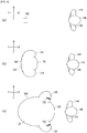
FIG. 4 is a view illustrating a process in which the cushion inFIG. 3(a) restrains a passenger. -
FIG. 5 is a view illustrating a process in which the cushion inFIG. 3(a) restrains a passenger. -
FIG. 6 is a view illustrating a modified example of the cushion inFIG. 3(a) , etc. -
FIG. 7 is a view illustrating a modified example of the cushion inFIG. 3(a) , etc. -
FIG. 8 is a view illustrating a modified example of the cushion inFIG. 3(a) , etc. -
FIG. 9 is a view illustrating a modified example of the cushion inFIG. 3(a) , etc. - 100...Airbag apparatus, 102...Instrument panel, 104...Seat, 106...Housing part, 107...Cover, 108...Cushion, 118...Inflator, 120...Windshield, 122...Base, 124, 126...Protrusion part, 125, 127...Tip of the protrusion part, 128...Front restraining part, 130, 132...Inner tether, 134, 136...Outer tether, 138...One end of the inner tether, 139...Other end of the inner tether, 140...One end of the outer tether, 141...Other end of the outer tether, 142 Base of the protrusion part, 144...Passenger, 146...Head, 148...Temporal region of the head, 150, 152...Force applied to the protrusion part, 156...Rotation of the head, 158a to 158c...Inflated region, 200...Cushion of Modified Example 1, 202, 204...Inner tether, 203...Rear end of the inner tether, 220...Cushion of Modified Example 2, 222, 224...Inner tether, 240...Cushion of Modified Example 3, 242, 244...Outer tether, 246, 248...Rear end of the outer tether, 260...Cushion of Modified Example 4, 262, 264...Outer tether, 266, 268...Rear end of the outer tether, 270, 272...Side part of the protrusion part, 280...Cushion of Modified Example 5, 300...Cushion of Modified Example 6, 302, 304...Outer tether, 320...Cushion of Modified Example 7, 322...Inner tether, 340...Cushion of Modified Example 8, 342, 344...Inner tether, 346, 348, 350...Inflated region, 360...Cushion of Modified Example 9, 362...Curtain airbag
- Preferred embodiments according to the present invention will hereinafter be described in detail with reference to the appended drawings. The dimensions, materials, other specific numerical values, etc. indicated in such embodiments are mere exemplifications for ease of understanding of the invention and do not limit the present invention unless otherwise noted. Note that in the present specification and drawings, elements having substantially identical functions and configurations are labeled with identical symbols to omit redundant descriptions along with the illustration of elements not directly related to the present invention.
-
FIG. 1 is a view illustrating the outline of anairbag apparatus 100 according to an embodiment of the present invention.FIG. 1(a) is a view illustrating a vehicle prior to the operation of theairbag apparatus 100. InFIG. 1(a) and other drawings, the anteroposterior direction of the vehicle is indicated by arrows F (Forward) and B (Back), respectively, the left and right in the width direction of the vehicle are respectively indicated by arrows L (Left) and R (Right), and the vertical direction of the vehicle is indicated by arrows U (up) and D (down), respectively. - In the present embodiment, the
airbag apparatus 100 is implemented as a passenger bag for a passenger seat (seat 104 on the right in the front row) in a vehicle with the steering wheel on the left side. Hereinafter, in order to provide descriptions assuming theseat 104 on the right in the front row, for example, the outside of the vehicle in the width direction of the vehicle means the right of the vehicle, while the inside of the vehicle in the width direction of the vehicle means the left of the vehicle. - An airbag cushion (hereinafter, a cushion 108 (see
FIG. 1(b) ) of theairbag apparatus 100 is housed in ahousing part 106 provided in aninstrument panel 102. Thehousing part 106 is installed at the front of the vehicle of theseat 104, while, in addition to thecushion 108, an inflator 118 (seeFIG. 3(a) ) serving as a gas generator is also housed in thehousing part 106. -
FIG. 1(b) is a view illustrating a vehicle after the operation of theairbag apparatus 100 inFIG. 1(a) . Thecushion 108 is normally housed in the housing part 106 (seeFIG. 1(a) ), in addition to expanding and deploying from in front of theseat 104. Thecushion 108 is bag shaped and formed by overlapping and sewing; alternatively, multiple base cloths (configuring the surface thereof) are adhered and overlapped or formed by spinning and weaving using an OPW (One-Piece Woven), etc. -
FIG. 2 is a view illustrating acushion 108 during expansion and deployment ofFIG. 1(b) in each direction.FIG. 2(a) is a perspective view illustrating thecushion 108 inFIG. 1(b) when seen from the lower left side at the rear of the vehicle. Thecushion 108 according to the present embodiment roughly has: a base 122; and twoprotrusion parts base 122. - The
base 122 is a part occupying the majority of thecushion 108. The face of the base 122 on the rear of the vehicle serves as a front restrainingpart 128, restraining thehead 146 of a passenger 144 (seeFIG. 5(b) ) from the front of the vehicle. Theprotrusion parts part 128 in the width direction of the vehicle and protrude and expand further towards the rear of the vehicle than the front restrainingpart 128, mainly restraining the temporal region of thehead 148 of thepassenger 144. -
FIG. 2(b) is a view illustrating thecushion 108 inFIG. 1(b) when seen from the inside of the vehicle. Thebase 122 expands and deploys from the housing part 106 (seeFIG. 1(a) ) towards the rear of the vehicle so as to be embedded between the upper surface of theinstrument panel 102 and thewindshield 120. Theprotrusion parts -
FIG. 3 is a cross sectional view of thecushion 108 inFIG. 2(b) .FIG. 3(a) is an A-A cross sectional view of thecushion 108 inFIG. 2(b) . Two kinds of tethers consisting ofinner tethers outer tethers cushion 108 according to the present embodiment. Theinner tethers outer tethers cushion 108 by pulling each part of thecushion 108, wherein tension is applied to both theinner tethers outer tethers cushion 108 expands and deploys. Theinner tethers outer tethers cushion 108. -
FIG. 3(b) is a B-B cross sectional view of thecushion 108 inFIG. 3(a) . Theinner tether 130 representing theinner tethers FIG. 3(b) . Because theinner tethers inner tether 130 is typically referred to. - The
inner tether 130 is provided so as to gradually spread from the front to the rear of the vehicle, with oneend 138 thereof bonded to the front restrainingpart 128. Theother end 139 of theinner tether 130 is the part facing the front restrainingpart 128 inside thecushion 108 and is specifically connected to the bottom part on the front of the vehicle contacting the instrument panel 102 (seeFIG. 1(a) ). This configuration enables theinner tether 130 to efficiently pull the front restrainingpart 128 towards the front of the vehicle as thecushion 108 expands and deploys. Thisinner tether 130 can regulate the position of the front restrainingpart 128, in addition to improving the passenger restraining force at the front restrainingpart 128. -
FIG. 3(c) is a C-C cross sectional view of the cushion inFIG. 3(a) . Theouter tether 134 representing theouter tethers FIG. 3(c) . Because theouter tethers outer tether 134 is typically referred to. - As illustrated in
FIG. 3(c) , theouter tether 134 is also provided so as to gradually spread from the front to the rear of the vehicle, with oneend 140 thereof connected to abase 142 of theprotrusion part 124 on the inner tether side. Theother end 141 of theouter tether 134 is the part facing theprotrusion part 124 inside thecushion 108 and is connected to the bottom part on the front of the vehicle contacting the instrument panel 102 (seeFIG. 1(a) ). This configuration allows theouter tether 134 to efficiently pull theprotrusion part 124 as thecushion 108 expands and deploys, making it possible to maintain the shape protruding towards the rear of the vehicle of theprotrusion part 124. - Once again in reference to
FIG. 3(a) . A portion of theinflator 118 is inserted into thecushion 108. Theinflator 118 is operated upon receiving a detection signal of an impact from a sensor (not illustrated), so as to supply gas to thecushion 108. Thecushion 108 starts to expand by the gas from theinflator 118, after which the expansion pressure thereof cleaves a cover 107 (seeFIG. 1(a) ) of thehousing part 106, etc., and then expands and deploys towards theseat 104 so as to restrain the passenger from the front of the vehicle. - The
inflator 118 is disc shaped, with a portion thereof inserted into thebase 122, and fixed to a rigid part of the vehicle, such as a cross beam, inside the housing part 106 (seeFIG. 1(a) ). Exemplary currently prevailing inflators include: a type which is filled with a gas generating agent and burns the agent to generate gas; a type which is filled with compressed gas and supply gas without generating heat; or a hybrid type which utilizes both combustion gas and compressed gas; etc. Any type of the inflator 118 can be utilized. - The
inner tethers outer tethers cushion 108, in addition to further improving the passenger restraining force of theprotrusion parts inner tethers outer tethers cushion 108 restrains thepassenger 144 will hereinafter be described with reference toFIGS. 4 ,5 . -
FIGS. 4 and5 are views illustrating a process in which thecushion 108 inFIG. 3(a) restrains apassenger 144. As illustrated inFIG. 4(a) , thecushion 108 is housed in the vehicle in front of thepassenger 144 occupying theseat 104. As illustrated inFIG. 4(b) , when an impact occurs on the vehicle, an operation signal is transmitted from a sensor (not illustrated) to theairbag apparatus 100, after which thecushion 108 cleaves the cover 107 (seeFIG. 1(a) ) so as to expand and deploy. In addition, as illustrated inFIG. 4(c) , thebase 122 of thecushion 108 expands, while theprotrusion parts cushion 108 expands from both sides of the front restrainingpart 128 in the width direction of the vehicle. - As illustrated in
FIG. 5(a) , thecushion 108 expands from the front towards the rear of the vehicle so as to restrain thehead 146 of thepassenger 144 with the front restrainingpart 128. However, in an oblique collision, thepassenger 144 may move from theseat 104 towards the front of the vehicle, in addition to moving obliquely to the front of the inside of the vehicle. Accordingly, in the present embodiment, theprotrusion parts part 128 in the width direction of the vehicle towards the rear of the vehicle. -
FIG. 5(b) is a view in which thepassenger 144 inFIG. 5(a) has further entered thecushion 108 side. As illustrated inFIG. 5(b) , for example, if thepassenger 144 moves towards the left front, thecushion 108 restrains thehead 146 of thepassenger 144 with the front restrainingpart 128 from the front of the vehicle, in addition to restraining thehead 146 of thepassenger 144 with theprotrusion part 124 from the temporal region of thehead 148 side. - As has been described with reference to
FIG. 3(a) , in the present embodiment, when tension is applied to theinner tethers part 128 towards the front of the vehicle, theouter tethers inner tethers part 128, with the force towards theinner tethers outer tethers outer tethers bases 142, 143 of theprotrusion part 124 on theinner tethers inner tethers protrusion parts outer tethers force protrusion parts FIG. 5(b) in the direction narrowing the interval therebetween, such that theprotrusion parts head 146 of thepassenger 144 in such a motion so as to enclose thehead 146 from both sides thereof. This operation enables theprotrusion parts head 146 of thepassenger 144. - Here, during an oblique collision, etc., when the
head 146 of thepassenger 144 which moves towards the oblique front contacts thecushion 108 at the front of theseat 104, thehead 146 may experience clockwise rotary force (rotation 156 indicated by arrows) about the neck when seen from above. Therotation 156 of thehead 146 in this way has been found to easily increase the injury value of thepassenger 144. However, in the present embodiment, the front restrainingpart 128 and theprotrusion part 124 can positively restrain the range from the front of thehead 146 to the temporal region of thehead 148, decreasing or negating and absorbing therotation 156 arising in thehead 146. This configuration can decrease the angular speed of thehead 146 of therotation 156 of thepassenger 144, in addition to suppressing the injury value of thehead 146 caused by therotation 156. - Once again in reference to
FIG. 3(a) . In thecushion 108 according to the present embodiment, in the front restrainingpart 128, theregion 158b between theinner tethers regions inner tethers outer tethers - Generally, the pressure and the curvature radius affect the tension of the base cloth. The
cushion 108 expands by means of the pressure of the gas received from oneinflator 118. Therefore, in accordance with the large/small relation of the curvature radius, the case in whichregions 158a to 158c in which the front restrainingpart 128 inflated between each tether is formed exhibits a lower tension of the base cloth than the case in which the overallfront restraining part 128 uniformly expands. In this way, the front restrainingpart 128 according to the present embodiment has the tension suppressed and can flexibly receive thehead 146 of thepassenger 144, in addition to efficiently suppressing the rotation 156 (seeFIG. 5(b) ) of thehead 146. -
FIGS. 6 to 9 are views illustrating modified examples of thecushion 108 inFIG. 3(a) , etc. Hereinafter, the same components as described above are labeled with the same symbols, with the descriptions thereof omitted. Moreover, the same names as the components described above shall have the same functions unless otherwise indicated even when labeled with different symbols. -
FIG. 6(a) is a view illustrating Modified Example 1 of thecushion 108 corresponding toFIG. 3(a) . In acushion 200 illustrated inFIG. 6(a) , theinner tethers outer tethers cushion 200, for example, the length of theinner tether 202 is set to be shorter than theouter tether 134 by approximately the length D1, such that therear end 203 of theinner tether 202 is connected to the front restrainingpart 128 more to the front of the vehicle than therear end 140 of theouter tether 134. In other words, upon completion of the expansion and deployment of thecushion 200, the length of theouter tether 134 is set to be longer than theinner tether 202 by approximately the length D1, such that therear end 140 of theouter tether 134 is connected to thebase 142 of theprotrusion part 124 more to the rear of the vehicle than therear end 204 of theinner tether 202. - With the abovementioned configuration, when the
cushion 200 expands and deploys from the front towards the rear of the vehicle, the application of tension to theinner tethers outer tethers outer tethers inner tethers inner tethers protrusion parts -
FIG. 6(b) is a view illustrating Modified Example 2 of thecushion 108 corresponding toFIG. 3(a) . In acushion 220 illustrated inFIG. 6(b) , compared with thecushion 200 inFIG. 6(a) ,inner tethers outer tethers inner tethers outer tethers outer tethers inner tethers outer tethers protrusion parts -
FIG. 7(a) is a view illustrating Modified Example 3 of thecushion 108 corresponding toFIG. 3(a) . In thecushion 240 illustrated inFIG. 7(a) , theouter tethers inner tethers outer tethers tips protrusion parts outer tethers inner tethers protrusion parts -
FIG. 7(b) is a view illustrating Modified Example 4 of thecushion 108 corresponding toFIG. 3(a) . Also in thecushion 260 illustrated inFIG. 7(b) , theouter tethers inner tethers outer tethers side parts protrusion parts inner tethers outer tethers inner tethers protrusion parts outer tethers tips protrusion parts head 146 of the passenger 144 (seeFIG. 5(b) ). -
FIG. 8(a) is a view illustrating Modified Example 5 of thecushion 108 corresponding toFIG. 3(a) . In acushion 280 illustrated inFIG. 8(a) , theouter tethers outer tethers -
FIG. 8(b) is a view illustrating Modified Example 6 of thecushion 108 corresponding toFIG. 3(a) . In thecushion 300 illustrated inFIG. 8(b) , theouter tethers inner tethers inner tethers outer tethers - As mentioned above, the front of the vehicle of the
inner tethers outer tethers inner tethers outer tethers part 128 and theprotrusion parts - As a further modified example of the
cushion 300, thecushion 300 is fixed to the cross beam, etc. in the vicinity of theinflator 118. Therefore, if the front ends of theinner tethers inflator 118 of thebase 122. In this example as well, theinner tethers part 128, while theouter tethers protrusion parts -
FIG. 8(c) is a view illustrating Modified Example 7 of thecushion 108 corresponding toFIG. 3(a) . In thecushion 320 illustrated inFIG. 8(c) , only oneinner tether 322 is provided. Only theinner tether 322 can also draw theouter tethers -
FIG. 9(a) is a view illustrating Modified Example 8 of thecushion 108 corresponding toFIG. 3(b) . In thecushion 340 illustrated inFIG. 9(a) , theinner tethers inner tethers part 128 so as to apply force towards theinner tethers outer tethers 134, 136 (seeFIG. 3(a) ). - Moreover, in the
cushion 340, aninflated region 346 is formed between theinner tether 342 and theinner tether 344, whileinflated regions FIG. 3(a) , the case in which the front restrainingpart 128 is sectioned and inflated between each tether exhibits a lower tension of the base cloth than the case in which the overallfront restraining part 128 uniformly expands. Theinflated regions head 146 of the passenger 144 (seeFIG. 5(b) ), in addition to efficiently suppressing therotation 156 of thehead 146. -
FIG. 9(b) is a view illustrating Modified Example 9 of thecushion 108 corresponding toFIG. 3(a) . As in thecushion 360 illustrated inFIG. 9(b) , only oneprotrusion part 124 can be provided. For example, in the case of a passenger bag provided on the right in the width direction of the vehicle as illustrated inFIG. 1(b) , acurtain airbag 362 may be provided to the immediate left. In this case, even when theprotrusion part 124 and theouter tether 134 are provided only to the left of thecushion 360 in the width direction of the vehicle (inside of the vehicle), and the protrusion part 126 (seeFIG. 3(a) ) is omitted to the right in the width direction of the vehicle to implement a restraint using thecurtain airbag 362, the injury value of the passenger 144 (seeFIG. 5(b) ) towards the inside of the vehicle during an oblique collision can be efficiently suppressed to implement restraint. - In this way, the
protrusion part 124 and theouter tether 134 can be provided on either side of a cushion 36 in the width direction of the vehicle to suppress the injury value of the passenger. Moreover, as long as the shape of thebase 122 of thecushion 360 is maintained, theinner tethers part 128 in the width direction of the vehicle together with theouter tether 134. - While the preferred embodiments according to the present invention have been thus described in detail with reference to the appended drawings, needless to say, the present invention is not limited to the examples according to the present invention. Those skilled in the art may clearly consider various modified examples or correction examples within the scope described in the Scope of the Patent Claims, which are also naturally understood to belong within the technical scope of the present invention.
- The present invention may be utilized in an airbag apparatus that includes a bag shaped cushion which is installed in a vehicle and expands and deploys from in front of a seat.
Claims (9)
- An airbag apparatus, comprising a bag shaped cushion which is installed in a vehicle and expands and deploys from in front of a seat;
the cushion comprising:a front restraining part which restrains the head of a passenger from the front of a vehicle; andat least one protrusion part which is provided beside the front restraining part in the width direction of the vehicle and is capable of protruding and expanding further towards the rear of the vehicle than the front restraining part; andthe airbag apparatus further comprising, inside the cushion:at least one inner tether having one end which is connected to the front restraining part and to which tension is applied to pull the front restraining part towards the front of the vehicle; andan outer tether having one end connected to the protrusion part and to which tension is applied to pull the protrusion part towards the front of the vehicle;wherein, when tension is applied to the inner tether, force towards the inner tether is applied to the outer tether. - The airbag apparatus according to claim 1, wherein the application of tension to the inner tether is completed prior to applying tension to the outer tether.
- The airbag apparatus according to claim 1 or 2, wherein:the cushion expands from the front towards the rear of the vehicle, andthe outer tether is connected to the protrusion part further to the rear of the vehicle than the inner tether.
- The airbag apparatus according to any one of claims 1 to 3, wherein the outer tether is connected to the base on the inner tether side of the protrusion part.
- The airbag apparatus according to any one of claims 1 to 3, wherein the outer tether is connected to the tip of the protrusion part.
- The airbag apparatus according to any one of claims 1 to 3, wherein the outer tether is connected to the side part of the protrusion part on the inner tether side.
- The airbag apparatus according to any one of claims 1 to 6, wherein:the other end of the inner tether is connected to the part facing the front restraining part inside the cushion, andthe other end of the outer tether is connected to the part facing the protrusion part inside the cushion.
- The airbag apparatus according to any one of claims 1 to 7, wherein the protrusion part is provided on both sides of the front restraining part in the width direction of the vehicle.
- The airbag apparatus according to any one of claims 1 to 8, wherein the region of the front restraining part between the two adjacent tethers included in the inner tether or the outer tether is inflated towards the rear of the vehicle.
Applications Claiming Priority (2)
| Application Number | Priority Date | Filing Date | Title |
|---|---|---|---|
| JP2017090627 | 2017-04-28 | ||
| PCT/JP2018/000685 WO2018198443A1 (en) | 2017-04-28 | 2018-01-12 | Air bag device |
Publications (3)
| Publication Number | Publication Date |
|---|---|
| EP3617008A1 true EP3617008A1 (en) | 2020-03-04 |
| EP3617008A4 EP3617008A4 (en) | 2020-12-09 |
| EP3617008B1 EP3617008B1 (en) | 2025-04-30 |
Family
ID=63918269
Family Applications (1)
| Application Number | Title | Priority Date | Filing Date |
|---|---|---|---|
| EP18789873.9A Active EP3617008B1 (en) | 2017-04-28 | 2018-01-12 | Air bag device |
Country Status (4)
| Country | Link |
|---|---|
| US (1) | US11167717B2 (en) |
| EP (1) | EP3617008B1 (en) |
| JP (1) | JP6798013B2 (en) |
| WO (1) | WO2018198443A1 (en) |
Families Citing this family (14)
| Publication number | Priority date | Publication date | Assignee | Title |
|---|---|---|---|---|
| KR20190101540A (en) * | 2018-02-23 | 2019-09-02 | 현대자동차주식회사 | Airbag apparatus for vehicle |
| JP6977678B2 (en) * | 2018-07-05 | 2021-12-08 | 豊田合成株式会社 | Passenger seat airbag device |
| CN110843718B (en) * | 2018-07-30 | 2025-07-29 | 奥托立夫开发公司 | Safety air bag |
| JP7095564B2 (en) * | 2018-11-16 | 2022-07-05 | 豊田合成株式会社 | Airbag device |
| KR102604711B1 (en) * | 2019-02-27 | 2023-11-22 | 아우토리브 디벨롭먼트 아베 | airbag device |
| JP6918040B2 (en) * | 2019-03-20 | 2021-08-11 | オートリブ ディベロップメント エービー | Airbag device |
| JP7093014B2 (en) * | 2019-03-28 | 2022-06-29 | 豊田合成株式会社 | Airbag for steering wheel |
| US11548468B2 (en) * | 2019-09-30 | 2023-01-10 | Toyoda Gosei Co., Ltd. | Occupant protection system |
| EP4163158A4 (en) * | 2020-06-08 | 2024-07-17 | Autoliv Development AB | Driver seat airbag device |
| US11613225B2 (en) * | 2021-01-20 | 2023-03-28 | Autoliv Asp, Inc. | Airbag device |
| JP7736494B2 (en) * | 2021-09-15 | 2025-09-09 | 株式会社Subaru | Vehicle airbag device |
| KR20240071137A (en) * | 2022-11-15 | 2024-05-22 | 현대모비스 주식회사 | Airbag apparatus for mobility |
| WO2024122439A1 (en) * | 2022-12-08 | 2024-06-13 | オートリブ ディベロップメント エービー | Airbag device |
| KR20240139416A (en) | 2023-03-14 | 2024-09-23 | 현대모비스 주식회사 | Air bag device |
Family Cites Families (24)
| Publication number | Priority date | Publication date | Assignee | Title |
|---|---|---|---|---|
| US7862073B2 (en) * | 2008-06-05 | 2011-01-04 | Gm Global Technology Operations, Inc. | Split top air bag assembly |
| JP4992853B2 (en) * | 2008-08-06 | 2012-08-08 | タカタ株式会社 | Airbag device |
| JP5572597B2 (en) | 2011-06-30 | 2014-08-13 | 富士重工業株式会社 | Crew protection device |
| US9561774B2 (en) * | 2014-04-24 | 2017-02-07 | Ford Global Technologies, Llc | Winged driver airbag |
| JP6365327B2 (en) * | 2014-08-12 | 2018-08-01 | 豊田合成株式会社 | Airbag device for passenger seat |
| US9187055B1 (en) * | 2014-12-02 | 2015-11-17 | Toyoda Gosei Co., Ltd. | Vehicle airbag |
| JP6337782B2 (en) | 2015-01-20 | 2018-06-06 | 豊田合成株式会社 | Airbag device for passenger seat |
| DE102015004956A1 (en) * | 2015-04-17 | 2016-10-20 | Trw Automotive Gmbh | Frontal gas bag for vehicle occupants and gas bag module |
| JP6500275B2 (en) * | 2015-09-24 | 2019-04-17 | 豊田合成株式会社 | Passenger airbag device |
| US9676355B2 (en) * | 2015-10-12 | 2017-06-13 | Autoliv Asp, Inc. | Frontal airbag systems for oblique crash protection |
| KR101755989B1 (en) * | 2016-03-04 | 2017-07-10 | 현대자동차주식회사 | Front airbag for vehicle |
| US10427638B2 (en) * | 2016-06-08 | 2019-10-01 | Autoliv Asp, Inc. | Frontal airbag assemblies for reducing rotational velocity of a head of an occupant |
| DE102016119387A1 (en) * | 2016-10-12 | 2018-04-12 | Trw Automotive Gmbh | Front airbag for a vehicle occupant |
| US10293775B2 (en) * | 2016-10-21 | 2019-05-21 | Autoliv Asp, Inc. | Frontal airbag assemblies for reducing rotational velocity of a head of an occupant |
| US20180134244A1 (en) * | 2016-11-11 | 2018-05-17 | Hyundai Motor Company | Front airbag for vehicle |
| JP6711254B2 (en) * | 2016-12-07 | 2020-06-17 | 豊田合成株式会社 | Airbag device for passenger seat |
| US10493941B2 (en) * | 2016-12-14 | 2019-12-03 | Ford Global Technologies, Llc | Door mounted airbag assembly with concave surface |
| DE102017117015A1 (en) * | 2017-01-31 | 2018-08-02 | Trw Automotive Gmbh | Frontal airbag |
| DE102017117014A1 (en) * | 2017-01-31 | 2018-08-02 | Trw Automotive Gmbh | Frontal airbag |
| JP6750554B2 (en) * | 2017-04-14 | 2020-09-02 | トヨタ自動車株式会社 | Passenger airbag device and airbag folding method |
| US10343641B2 (en) * | 2017-04-17 | 2019-07-09 | Ford Global Technologies, Llc | Vehicle airbag |
| JP6819472B2 (en) * | 2017-06-08 | 2021-01-27 | 豊田合成株式会社 | Passenger seat airbag device |
| JP6881364B2 (en) * | 2018-03-16 | 2021-06-02 | 豊田合成株式会社 | Passenger seat airbag device |
| EP3543075B1 (en) * | 2018-03-23 | 2020-11-11 | Autoliv Development AB | Airbag device |
-
2018
- 2018-01-12 US US16/609,092 patent/US11167717B2/en active Active
- 2018-01-12 EP EP18789873.9A patent/EP3617008B1/en active Active
- 2018-01-12 WO PCT/JP2018/000685 patent/WO2018198443A1/en not_active Ceased
- 2018-01-12 JP JP2019515092A patent/JP6798013B2/en active Active
Also Published As
| Publication number | Publication date |
|---|---|
| JPWO2018198443A1 (en) | 2020-01-09 |
| EP3617008B1 (en) | 2025-04-30 |
| WO2018198443A1 (en) | 2018-11-01 |
| EP3617008A4 (en) | 2020-12-09 |
| US11167717B2 (en) | 2021-11-09 |
| US20200086821A1 (en) | 2020-03-19 |
| JP6798013B2 (en) | 2020-12-09 |
Similar Documents
| Publication | Publication Date | Title |
|---|---|---|
| EP3617008B1 (en) | Air bag device | |
| JP6714750B2 (en) | Airbag device | |
| CN110293929B (en) | Airbag device | |
| JP6529644B2 (en) | Air bag device | |
| JP5639263B2 (en) | Curtain airbag device for vehicle | |
| WO2016021381A1 (en) | Airbag apparatus | |
| WO2018105324A1 (en) | Side air bag device | |
| JP6496420B2 (en) | Airbag device | |
| KR20190071509A (en) | Air bag device for panorama roof | |
| CN110053580B (en) | Airbag device | |
| JP2020037382A (en) | Airbag device | |
| KR20200137994A (en) | Side airbag device | |
| JP6450833B2 (en) | Airbag device | |
| KR20190071508A (en) | Air bag device for panorama roof | |
| WO2018061373A1 (en) | Airbag device | |
| JP2016153262A (en) | Air bag device | |
| JP5972856B2 (en) | Curtain airbag device | |
| JP6799621B2 (en) | Airbag device | |
| JP6559847B2 (en) | Airbag device | |
| JP5990156B2 (en) | Curtain airbag device | |
| WO2015146361A1 (en) | Curtain air bag system | |
| KR20210136959A (en) | Side airbag device | |
| JP2019077216A (en) | Side airbag device | |
| JP2023142900A (en) | Vehicle airbag device | |
| JP2014218161A (en) | Side airbag device |
Legal Events
| Date | Code | Title | Description |
|---|---|---|---|
| STAA | Information on the status of an ep patent application or granted ep patent |
Free format text: STATUS: THE INTERNATIONAL PUBLICATION HAS BEEN MADE |
|
| PUAI | Public reference made under article 153(3) epc to a published international application that has entered the european phase |
Free format text: ORIGINAL CODE: 0009012 |
|
| STAA | Information on the status of an ep patent application or granted ep patent |
Free format text: STATUS: REQUEST FOR EXAMINATION WAS MADE |
|
| 17P | Request for examination filed |
Effective date: 20191126 |
|
| AK | Designated contracting states |
Kind code of ref document: A1 Designated state(s): AL AT BE BG CH CY CZ DE DK EE ES FI FR GB GR HR HU IE IS IT LI LT LU LV MC MK MT NL NO PL PT RO RS SE SI SK SM TR |
|
| AX | Request for extension of the european patent |
Extension state: BA ME |
|
| DAV | Request for validation of the european patent (deleted) | ||
| DAX | Request for extension of the european patent (deleted) | ||
| A4 | Supplementary search report drawn up and despatched |
Effective date: 20201109 |
|
| RIC1 | Information provided on ipc code assigned before grant |
Ipc: B60R 21/233 20060101ALI20201103BHEP Ipc: B60R 21/205 20110101AFI20201103BHEP Ipc: B60R 21/2338 20110101ALI20201103BHEP |
|
| STAA | Information on the status of an ep patent application or granted ep patent |
Free format text: STATUS: EXAMINATION IS IN PROGRESS |
|
| 17Q | First examination report despatched |
Effective date: 20210921 |
|
| GRAP | Despatch of communication of intention to grant a patent |
Free format text: ORIGINAL CODE: EPIDOSNIGR1 |
|
| STAA | Information on the status of an ep patent application or granted ep patent |
Free format text: STATUS: GRANT OF PATENT IS INTENDED |
|
| INTG | Intention to grant announced |
Effective date: 20240722 |
|
| GRAJ | Information related to disapproval of communication of intention to grant by the applicant or resumption of examination proceedings by the epo deleted |
Free format text: ORIGINAL CODE: EPIDOSDIGR1 |
|
| STAA | Information on the status of an ep patent application or granted ep patent |
Free format text: STATUS: EXAMINATION IS IN PROGRESS |
|
| GRAP | Despatch of communication of intention to grant a patent |
Free format text: ORIGINAL CODE: EPIDOSNIGR1 |
|
| STAA | Information on the status of an ep patent application or granted ep patent |
Free format text: STATUS: GRANT OF PATENT IS INTENDED |
|
| INTC | Intention to grant announced (deleted) | ||
| INTG | Intention to grant announced |
Effective date: 20241128 |
|
| GRAS | Grant fee paid |
Free format text: ORIGINAL CODE: EPIDOSNIGR3 |
|
| GRAA | (expected) grant |
Free format text: ORIGINAL CODE: 0009210 |
|
| STAA | Information on the status of an ep patent application or granted ep patent |
Free format text: STATUS: THE PATENT HAS BEEN GRANTED |
|
| AK | Designated contracting states |
Kind code of ref document: B1 Designated state(s): AL AT BE BG CH CY CZ DE DK EE ES FI FR GB GR HR HU IE IS IT LI LT LU LV MC MK MT NL NO PL PT RO RS SE SI SK SM TR |
|
| REG | Reference to a national code |
Ref country code: CH Ref legal event code: EP Ref country code: GB Ref legal event code: FG4D |
|
| REG | Reference to a national code |
Ref country code: IE Ref legal event code: FG4D |
|
| REG | Reference to a national code |
Ref country code: DE Ref legal event code: R096 Ref document number: 602018081543 Country of ref document: DE |
|
| REG | Reference to a national code |
Ref country code: NL Ref legal event code: MP Effective date: 20250430 |
|
| REG | Reference to a national code |
Ref country code: AT Ref legal event code: MK05 Ref document number: 1789774 Country of ref document: AT Kind code of ref document: T Effective date: 20250430 |
|
| PG25 | Lapsed in a contracting state [announced via postgrant information from national office to epo] |
Ref country code: PT Free format text: LAPSE BECAUSE OF FAILURE TO SUBMIT A TRANSLATION OF THE DESCRIPTION OR TO PAY THE FEE WITHIN THE PRESCRIBED TIME-LIMIT Effective date: 20250901 Ref country code: FI Free format text: LAPSE BECAUSE OF FAILURE TO SUBMIT A TRANSLATION OF THE DESCRIPTION OR TO PAY THE FEE WITHIN THE PRESCRIBED TIME-LIMIT Effective date: 20250430 Ref country code: ES Free format text: LAPSE BECAUSE OF FAILURE TO SUBMIT A TRANSLATION OF THE DESCRIPTION OR TO PAY THE FEE WITHIN THE PRESCRIBED TIME-LIMIT Effective date: 20250430 |
|
| REG | Reference to a national code |
Ref country code: LT Ref legal event code: MG9D |
|
| PG25 | Lapsed in a contracting state [announced via postgrant information from national office to epo] |
Ref country code: GR Free format text: LAPSE BECAUSE OF FAILURE TO SUBMIT A TRANSLATION OF THE DESCRIPTION OR TO PAY THE FEE WITHIN THE PRESCRIBED TIME-LIMIT Effective date: 20250731 Ref country code: NO Free format text: LAPSE BECAUSE OF FAILURE TO SUBMIT A TRANSLATION OF THE DESCRIPTION OR TO PAY THE FEE WITHIN THE PRESCRIBED TIME-LIMIT Effective date: 20250730 |
|
| PG25 | Lapsed in a contracting state [announced via postgrant information from national office to epo] |
Ref country code: PL Free format text: LAPSE BECAUSE OF FAILURE TO SUBMIT A TRANSLATION OF THE DESCRIPTION OR TO PAY THE FEE WITHIN THE PRESCRIBED TIME-LIMIT Effective date: 20250430 Ref country code: NL Free format text: LAPSE BECAUSE OF FAILURE TO SUBMIT A TRANSLATION OF THE DESCRIPTION OR TO PAY THE FEE WITHIN THE PRESCRIBED TIME-LIMIT Effective date: 20250430 |
|
| PG25 | Lapsed in a contracting state [announced via postgrant information from national office to epo] |
Ref country code: BG Free format text: LAPSE BECAUSE OF FAILURE TO SUBMIT A TRANSLATION OF THE DESCRIPTION OR TO PAY THE FEE WITHIN THE PRESCRIBED TIME-LIMIT Effective date: 20250430 |
|
| PG25 | Lapsed in a contracting state [announced via postgrant information from national office to epo] |
Ref country code: HR Free format text: LAPSE BECAUSE OF FAILURE TO SUBMIT A TRANSLATION OF THE DESCRIPTION OR TO PAY THE FEE WITHIN THE PRESCRIBED TIME-LIMIT Effective date: 20250430 |
|
| PG25 | Lapsed in a contracting state [announced via postgrant information from national office to epo] |
Ref country code: AT Free format text: LAPSE BECAUSE OF FAILURE TO SUBMIT A TRANSLATION OF THE DESCRIPTION OR TO PAY THE FEE WITHIN THE PRESCRIBED TIME-LIMIT Effective date: 20250430 |
|
| PG25 | Lapsed in a contracting state [announced via postgrant information from national office to epo] |
Ref country code: RS Free format text: LAPSE BECAUSE OF FAILURE TO SUBMIT A TRANSLATION OF THE DESCRIPTION OR TO PAY THE FEE WITHIN THE PRESCRIBED TIME-LIMIT Effective date: 20250731 |
|
| PG25 | Lapsed in a contracting state [announced via postgrant information from national office to epo] |
Ref country code: IS Free format text: LAPSE BECAUSE OF FAILURE TO SUBMIT A TRANSLATION OF THE DESCRIPTION OR TO PAY THE FEE WITHIN THE PRESCRIBED TIME-LIMIT Effective date: 20250830 |
|
| PG25 | Lapsed in a contracting state [announced via postgrant information from national office to epo] |
Ref country code: LV Free format text: LAPSE BECAUSE OF FAILURE TO SUBMIT A TRANSLATION OF THE DESCRIPTION OR TO PAY THE FEE WITHIN THE PRESCRIBED TIME-LIMIT Effective date: 20250430 |
|
| PG25 | Lapsed in a contracting state [announced via postgrant information from national office to epo] |
Ref country code: DK Free format text: LAPSE BECAUSE OF FAILURE TO SUBMIT A TRANSLATION OF THE DESCRIPTION OR TO PAY THE FEE WITHIN THE PRESCRIBED TIME-LIMIT Effective date: 20250430 Ref country code: SM Free format text: LAPSE BECAUSE OF FAILURE TO SUBMIT A TRANSLATION OF THE DESCRIPTION OR TO PAY THE FEE WITHIN THE PRESCRIBED TIME-LIMIT Effective date: 20250430 |
|
| PG25 | Lapsed in a contracting state [announced via postgrant information from national office to epo] |
Ref country code: CZ Free format text: LAPSE BECAUSE OF FAILURE TO SUBMIT A TRANSLATION OF THE DESCRIPTION OR TO PAY THE FEE WITHIN THE PRESCRIBED TIME-LIMIT Effective date: 20250430 |
|
| PG25 | Lapsed in a contracting state [announced via postgrant information from national office to epo] |
Ref country code: EE Free format text: LAPSE BECAUSE OF FAILURE TO SUBMIT A TRANSLATION OF THE DESCRIPTION OR TO PAY THE FEE WITHIN THE PRESCRIBED TIME-LIMIT Effective date: 20250430 |
|
| PG25 | Lapsed in a contracting state [announced via postgrant information from national office to epo] |
Ref country code: RO Free format text: LAPSE BECAUSE OF FAILURE TO SUBMIT A TRANSLATION OF THE DESCRIPTION OR TO PAY THE FEE WITHIN THE PRESCRIBED TIME-LIMIT Effective date: 20250430 Ref country code: SK Free format text: LAPSE BECAUSE OF FAILURE TO SUBMIT A TRANSLATION OF THE DESCRIPTION OR TO PAY THE FEE WITHIN THE PRESCRIBED TIME-LIMIT Effective date: 20250430 |
|
| PG25 | Lapsed in a contracting state [announced via postgrant information from national office to epo] |
Ref country code: IT Free format text: LAPSE BECAUSE OF FAILURE TO SUBMIT A TRANSLATION OF THE DESCRIPTION OR TO PAY THE FEE WITHIN THE PRESCRIBED TIME-LIMIT Effective date: 20250430 |
|
| REG | Reference to a national code |
Ref country code: DE Ref legal event code: R097 Ref document number: 602018081543 Country of ref document: DE |
|
| PLBE | No opposition filed within time limit |
Free format text: ORIGINAL CODE: 0009261 |
|
| STAA | Information on the status of an ep patent application or granted ep patent |
Free format text: STATUS: NO OPPOSITION FILED WITHIN TIME LIMIT |
|
| REG | Reference to a national code |
Ref country code: CH Ref legal event code: L10 Free format text: ST27 STATUS EVENT CODE: U-0-0-L10-L00 (AS PROVIDED BY THE NATIONAL OFFICE) Effective date: 20260311 |
|
| 26N | No opposition filed |
Effective date: 20260202 |
|
| PGFP | Annual fee paid to national office [announced via postgrant information from national office to epo] |
Ref country code: GB Payment date: 20260126 Year of fee payment: 9 |
|
| PGFP | Annual fee paid to national office [announced via postgrant information from national office to epo] |
Ref country code: DE Payment date: 20260127 Year of fee payment: 9 |
|
| PGFP | Annual fee paid to national office [announced via postgrant information from national office to epo] |
Ref country code: FR Payment date: 20260126 Year of fee payment: 9 |
|
| PG25 | Lapsed in a contracting state [announced via postgrant information from national office to epo] |
Ref country code: LT Free format text: LAPSE BECAUSE OF FAILURE TO SUBMIT A TRANSLATION OF THE DESCRIPTION OR TO PAY THE FEE WITHIN THE PRESCRIBED TIME-LIMIT Effective date: 20250430 |
|
| PG25 | Lapsed in a contracting state [announced via postgrant information from national office to epo] |
Ref country code: SE Free format text: LAPSE BECAUSE OF FAILURE TO SUBMIT A TRANSLATION OF THE DESCRIPTION OR TO PAY THE FEE WITHIN THE PRESCRIBED TIME-LIMIT Effective date: 20250430 |