EP3617001B1 - Method for mounting a portable remote control locomotive systems to a locomotive handrailing - Google Patents
Method for mounting a portable remote control locomotive systems to a locomotive handrailing Download PDFInfo
- Publication number
- EP3617001B1 EP3617001B1 EP19191281.5A EP19191281A EP3617001B1 EP 3617001 B1 EP3617001 B1 EP 3617001B1 EP 19191281 A EP19191281 A EP 19191281A EP 3617001 B1 EP3617001 B1 EP 3617001B1
- Authority
- EP
- European Patent Office
- Prior art keywords
- hook
- horizontal arm
- locomotive
- handrailing
- arm
- Prior art date
- Legal status (The legal status is an assumption and is not a legal conclusion. Google has not performed a legal analysis and makes no representation as to the accuracy of the status listed.)
- Active
Links
Images














Classifications
-
- B—PERFORMING OPERATIONS; TRANSPORTING
- B60—VEHICLES IN GENERAL
- B60R—VEHICLES, VEHICLE FITTINGS, OR VEHICLE PARTS, NOT OTHERWISE PROVIDED FOR
- B60R11/00—Arrangements for holding or mounting articles, not otherwise provided for
- B60R11/06—Arrangements for holding or mounting articles, not otherwise provided for for tools or spare parts
-
- B—PERFORMING OPERATIONS; TRANSPORTING
- B61—RAILWAYS
- B61C—LOCOMOTIVES; MOTOR RAILCARS
- B61C17/00—Arrangement or disposition of parts; Details or accessories not otherwise provided for; Use of control gear and control systems
- B61C17/12—Control gear; Arrangements for controlling locomotives from remote points in the train or when operating in multiple units
-
- B—PERFORMING OPERATIONS; TRANSPORTING
- B60—VEHICLES IN GENERAL
- B60R—VEHICLES, VEHICLE FITTINGS, OR VEHICLE PARTS, NOT OTHERWISE PROVIDED FOR
- B60R11/00—Arrangements for holding or mounting articles, not otherwise provided for
-
- B—PERFORMING OPERATIONS; TRANSPORTING
- B61—RAILWAYS
- B61L—GUIDING RAILWAY TRAFFIC; ENSURING THE SAFETY OF RAILWAY TRAFFIC
- B61L15/00—Indicators provided on the vehicle or train for signalling purposes
- B61L15/0018—Communication with or on the vehicle or train
- B61L15/0027—Radio-based, e.g. using GSM-R
-
- B—PERFORMING OPERATIONS; TRANSPORTING
- B60—VEHICLES IN GENERAL
- B60R—VEHICLES, VEHICLE FITTINGS, OR VEHICLE PARTS, NOT OTHERWISE PROVIDED FOR
- B60R11/00—Arrangements for holding or mounting articles, not otherwise provided for
- B60R2011/0001—Arrangements for holding or mounting articles, not otherwise provided for characterised by position
- B60R2011/004—Arrangements for holding or mounting articles, not otherwise provided for characterised by position outside the vehicle
-
- B—PERFORMING OPERATIONS; TRANSPORTING
- B60—VEHICLES IN GENERAL
- B60R—VEHICLES, VEHICLE FITTINGS, OR VEHICLE PARTS, NOT OTHERWISE PROVIDED FOR
- B60R11/00—Arrangements for holding or mounting articles, not otherwise provided for
- B60R2011/0042—Arrangements for holding or mounting articles, not otherwise provided for characterised by mounting means
-
- B—PERFORMING OPERATIONS; TRANSPORTING
- B61—RAILWAYS
- B61L—GUIDING RAILWAY TRAFFIC; ENSURING THE SAFETY OF RAILWAY TRAFFIC
- B61L29/00—Safety means for rail/road crossing traffic
- B61L29/24—Means for warning road traffic that a gate is closed or closing, or that rail traffic is approaching, e.g. for visible or audible warning
- B61L29/28—Means for warning road traffic that a gate is closed or closing, or that rail traffic is approaching, e.g. for visible or audible warning electrically operated
-
- B—PERFORMING OPERATIONS; TRANSPORTING
- B61—RAILWAYS
- B61L—GUIDING RAILWAY TRAFFIC; ENSURING THE SAFETY OF RAILWAY TRAFFIC
- B61L3/00—Devices along the route for controlling devices on the vehicle or train, e.g. to release brake or to operate a warning signal
- B61L3/02—Devices along the route for controlling devices on the vehicle or train, e.g. to release brake or to operate a warning signal at selected places along the route, e.g. intermittent control simultaneous mechanical and electrical control
- B61L3/08—Devices along the route for controlling devices on the vehicle or train, e.g. to release brake or to operate a warning signal at selected places along the route, e.g. intermittent control simultaneous mechanical and electrical control controlling electrically
- B61L3/12—Devices along the route for controlling devices on the vehicle or train, e.g. to release brake or to operate a warning signal at selected places along the route, e.g. intermittent control simultaneous mechanical and electrical control controlling electrically using magnetic or electrostatic induction; using radio waves
- B61L3/127—Devices along the route for controlling devices on the vehicle or train, e.g. to release brake or to operate a warning signal at selected places along the route, e.g. intermittent control simultaneous mechanical and electrical control controlling electrically using magnetic or electrostatic induction; using radio waves for remote control of locomotives
-
- G—PHYSICS
- G08—SIGNALLING
- G08B—SIGNALLING SYSTEMS, e.g. PERSONAL CALLING SYSTEMS; ORDER TELEGRAPHS; ALARM SYSTEMS
- G08B3/00—Audible signalling systems, e.g. audible personal calling systems
- G08B3/10—Audible signalling systems, e.g. audible personal calling systems using electric transmission; using electromagnetic transmission
-
- H—ELECTRICITY
- H04—ELECTRIC COMMUNICATION TECHNIQUE
- H04R—LOUDSPEAKERS, MICROPHONES, GRAMOPHONE PICK-UPS OR LIKE ACOUSTIC ELECTROMECHANICAL TRANSDUCERS; ELECTRIC HEARING AIDS; PUBLIC ADDRESS SYSTEMS
- H04R1/00—Details of transducers, loudspeakers or microphones
- H04R1/02—Casings; Cabinets ; Supports therefor; Mountings therein
- H04R1/026—Supports for loudspeaker casings
Definitions
- the present invention relates to a method for mounting portable remote control locomotive (RCL) systems to locomotive handrailing.
- RCL remote control locomotive
- Remote control locomotive (RCL) systems enable rail operators to remotely control operation of locomotives.
- a rail operator may use a RCL system to remotely control starting, stopping, speed, braking, switching, etc. of a locomotive.
- Document DE 200 13 623 discloses a hanger device that is adapted to be installed on the rear of an automobile seat 3 so as not to distract the driver's attention.
- Document WO 2016 127 018 A1 discloses devices, systems, and methods related to tracking location of operator control units for locomotives.
- assemblies e.g. , a quick connect mounting cradle assembly, etc.
- assemblies e.g. , a quick connect mounting cradle assembly, etc.
- portable remote RCL systems mountable to locomotive handrailing by such assemblies.
- the portable RCL systems may enable rail operators to use handheld remote controllers to remotely control operation (e.g., movement, etc. ) of locomotives from remote safe locations with a comprehensive view of each operation.
- a mounting assembly (broadly, an assembly) may include one or more adjustable features (e.g., slidably adjustable width top mounting hooks, etc. ) that allow or accommodate for mounting to locomotive handrailing having different hand rail configurations.
- the mounting assembly may be configured as a quick connect mounting assembly that is mountable to locomotive handrailing without the use of any tools.
- an enclosure e.g. , of a portable RCL system, etc.
- a pair of upper and lower members e.g., rods, cylindrical members, supports, etc.
- the enclosure's upper members and lower members may be configured ( e.g., sized, shaped, located, etc. ) to be engagingly received, respectively, within portions ( e.g., hook shaped portions, etc. ) of the upper arms ( e.g., pin locking arms, etc. ) and lower arms ( e.g., lower hooks, etc. ) of the mounting assembly.
- the upper arms of the mounting assembly may comprise two pin locking arms for securing the enclosure to the assembly.
- This exemplary embodiment may generally include two main pieces of hardware, which are the mounting assembly and the enclosure.
- the mounting assembly and enclosure are configured to allow the enclosure to quick mount to the mounting assembly without the use of any tools.
- this allows the overall weight to be distributed between these two pieces of hardware, which, in turn, allows for a faster safer installation.
- the lighter mounting assembly may first be installed to the handrailing of the locomotive without using any tools.
- the heavier enclosure including the RCL system components therein ( e.g., FIG. 38 , etc. ), may then be lifted without the additional weight of the previously installed mounting assembly.
- the enclosure may then be placed on and installed to the mounting assembly without the use of any tools.
- This exemplary embodiment may thus allow for a fast, safe, easy, and tool-less installation of a portable RCL system to handrailing of a locomotive, while also providing adjustability to account for a wide variety of locomotive handrails and obstructions near the site at which the mounting assembly will be installed.
- the audible alert system includes an outdoor speaker, an audio amplifier, and an audio file player.
- the audio amplifier and audio file player may be housed within an environmentally sealed enclosure, which provides protection from the environment.
- the speaker may be located on the front or back of a locomotive.
- the speaker is mounted to handrailing of a locomotive by using a quick connect mounting assembly disclosed herein.
- the quick connect mounting assembly may be configured to be mounted to the locomotive handrailing without the use of any tools.
- the audible alert system may be DC (direct current) powered and energy efficient.
- the speaker may comprise a 100 Watts, 12 volts direct current (VDC) speaker having a relatively thin or slim profile.
- VDC direct current
- the audible alert system may include a speaker having a different configuration ( e.g., higher or lower than 100 Watts, higher or lower than 12 VDC, etc. ) .
- the speaker may be lower in weight than and may replace the traditional pneumatic air horn and pneumatic bell currently used on locomotives.
- the audible alert system including the speaker, may provide the ability to program multiple sounds and modernize a pneumatic air horn while maintaining overall sound quality.
- the audio alert system may allow for reduced cost, complexity, and labor to include safety sounding devices onboard locomotives.
- the audio alert system may also provide integrated audio (voice and tones) and future capabilities to broadcast voice messages.
- FIGS. 1 through 8 illustrate a quick connect mounting cradle assembly 100 (broadly, an assembly).
- the assembly 100 may be used for mounting an enclosure 104 of a portable remote control locomotive (RCL) system 108 ( FIG. 38 ) to handrailing 116 of a locomotive 120.
- the assembly 100 may also ( FIG. 37 ), be used for mounting a speaker 132 to the locomotive handrailing 116.
- the portable RCL system 108 is an example only as the assembly 100 may also be used with other portable RCL systems in alternative exemplary embodiments.
- the assembly 100 generally includes upper and lower vertical supports, members, or arms 141, 142, an upper horizontal support, member, or arm 144, and a lower horizontal support, member, or arm 146.
- the arms 141, 142, 144, and 146 may comprise extruded parts or extrusions ( e.g. , extruded aluminum, etc. ) having T-slotted profiles, such as shown in FIGS. 22 , 26 , 27 , and 29 , etc.
- the lower horizontal arm 146 includes opposing upper and lower (or top and bottom) sides that respectively define upper and lower horizontally-extending slots 147.
- the upper and lower vertical arms 141, 142 are slidably coupled to the lower horizontal arm 146 such that the upper and lower vertical arms 141, 142 are horizontally slidable along the respectively upper and lower horizontally-extending slots 147.
- the upper and lower vertical arms 141, 142 may be slidably positioned at a center location or at an off-center ( e.g. , right or left of center, etc. ) location along the lower horizontal arm 146 depending on the particular handrail configuration and/or the presence of any obstructions near the site at which the assembly 100 will be installed.
- the upper horizontal arm 144 includes opposing upper and lower (or top and bottom) sides that respectively define upper and lower horizontally-extending slots 145.
- the upper vertical arm 141 is slidably coupled to the upper horizontal arm 144 such that the upper vertical arm 141 is horizontally slidable along the lower horizontally-extending slot 145. Accordingly, the upper vertical arm 141 may be slidably positioned at a center location or at an off-center ( e.g. , right or left of center, etc. ) location along the upper horizontal arm 144 depending on the particular handrail configuration and/or the presence of any obstructions near the site at which the assembly 100 will be installed.
- the sliding adjustability of the arms 141, 142, 144, 146 may help to account for a wide variety of locomotive handrails and obstructions near the site at which assembly 100 will be installed.
- the arms 142, 144, 146 may be slidably coupled by using brackets 149, mechanical fasteners 150, and self-aligning T-nuts with ball springs.
- Upper hook members 148 (broadly, support members) are respectively coupled ( e.g., mechanically fastened, etc. ) to opposing end portions of the upper horizontal arm 144.
- Lower hook members 152 (broadly, support members) are respectively coupled ( e.g. , mechanically fastened, etc. ) to opposing end portions of the lower horizontal arm 146.
- Each upper hook member 148 has a free end portion including or defining a hook 154.
- a locking bar or member 156 is pivotably coupled to the upper hook member 148 for pivotable movement relative to the hook 154 between an open position ( FIG. 17 ) and a closed position ( FIG. 1 ).
- a pin 158 e.g., a quick release pin, etc.
- a lanyard 160 is coupled to the pin 158 to allow for easier removal of the pin 158 from the aligned openings defined by the locking bar 156 and upper hook member 148.
- Each lower hook member 152 has a free end portion including or defining a hook 162.
- the upper and lower hooks 154 and 162 are configured to engagingly receive respective upper and lower members 164, 166 ( e.g., rods, cylindrical members, protruding supports, etc. ) extending outwardly from opposing sides of the enclosure 104 when the enclosure 104 is mounted or installed onto the assembly 100.
- the enclosure 104 may be lifted relative to the assembly 100 to thereby position the enclosure's upper and lower members 164, 166 within the corresponding upper and lower hooks 154, 162.
- the locking bars 156 may be pivoted relative to the corresponding hook 154 from the open position to the closed position in which the locking bars 156 are positioned generally over the corresponding upper members 164.
- the pins 158 may then be inserted into the aligned openings of the corresponding locking bar 156 and upper hook member 148 to thereby secure and retain the locking bars 156 in place over the upper members 164, thereby preventing the upper members 156 from being unintentionally removed or dislodged from the hooks 154.
- each pin 158 may be removed from the aligned openings of the corresponding locking bar 156 and upper hook member 148 via the lanyard 160.
- the locking bars 156 may be pivoted relative to the corresponding upper hook 154 from the closed position to the open position. Thereafter, the enclosure 104 may be lifted upwards relative to the assembly 100 to thereby remove the enclosure's upper and lower members 164, 166 from the corresponding upper and lower hooks 154, 162.
- the assembly 100 includes a pair of top mounting hooks 168 configured to be positioned over ( e.g., hooked onto, etc. ) locomotive handrailing 116.
- a retaining bar 170 is rotatably coupled to each hook 168 such that the retaining bar 170 is rotatable between an open position and a closed position ( FIG. 1 ).
- a spring may be provided for biasing the retaining bar 170 in the closed position. In the closed position, the retaining bar 170 may help to secure and retain the hook 168 onto the locomotive handrailing 116, thereby preventing the hook 168 from being unintentionally unhooked from the locomotive handrailing 116.
- the hooks 168 are slidably coupled to the upper horizontal arm 144 such that the hooks 168 are horizontally slidable along the horizontally-extending slot 145 defined along the top side of the upper horizontal arm 144. Accordingly, the width between the hooks 168 may be slidably adjusted as the hooks 168 are slidably moved along the upper horizontal arm 144 closer or farther away from each other depending on the particular handrail configuration and/or presence of any obstructions near the site at which the assembly 100 will be installed.
- the sliding width adjustability of the hooks 168 may thus help to account for a wide variety of locomotive handrails and obstructions near the site at which assembly 100 will be installed.
- the hooks 168 may be slidably coupled to the upper horizontal arm 144 using brackets 172, mechanical fasteners 174, and self-aligning T-nuts with ball springs.
- FIGS. 1 and 2 Also shown in FIGS. 1 and 2 are a pin 176 and a lanyard 178 (e.g. , keyring, cable, and pull-tab, etc. ) .
- the pin 176 is slidably coupled to the lower vertical arm 142 such that the pin 176 is vertically slidable along the vertically-extending slots 143 defined by the lower vertical arm 142. Accordingly, the pin 176 may be slidably positioned at various higher or lower locations along the lower vertical arm 142.
- the pin 176 and lanyard 178 may be used to tether the lower vertical arm 142 to a railing stanchion on the locomotive 120, which may help prevent the assembly 100 from swinging outwardly away ( e.g. , forward if mounted on the front of the locomotive, etc. ) from the locomotive handrailing during braking and coupling.
- FIGS. 9 through 17 illustrate an exemplary speaker 132 mounted to the assembly 100 via an exemplary speaker bracket 180 according to an exemplary embodiment.
- the speaker 132 is an example only as the assembly 100 may also be used with other speakers in alternative exemplary embodiments.
- the lower vertical arm 142 includes three vertically aligned fastener holes 182.
- three mechanical fasteners e.g., screws, etc.
- the speaker bracket 180 includes four fastener holes 184 ( FIG. 12 ) each adjacent a corresponding corner of the speaker bracket 180.
- four mechanical fasteners e.g., screws, etc.
- the speaker bracket 180, speaker 132, and lower vertical arm 142 may be configured differently in other embodiments, such as being configured to be coupled via other means besides mechanical fasteners and/or with more or less mechanical fasteners.
- the speaker 132 may be part of an audible alert system for a locomotive.
- FIG. 39 illustrates components of an audible alert system according to an exemplary embodiment embodying one or more aspects of the present disclosure.
- the audible alert system includes an outdoor speaker 132, an audio amplifier 136, and an audio file player 140 that may be used with an audible alert system.
- the audio amplifier 136 and the audio file player 140 are housed within an environmentally sealed enclosure, which provides protection from the environment.
- the speaker 132 may be lower in weight than and may replace the traditional pneumatic air horn and pneumatic bell on a locomotive.
- the audible alert system including the speaker 132, may provide the ability to program multiple sounds and modernize a pneumatic air horn while maintaining overall sound quality.
- the speaker 132 may be located on the front or back of a locomotive.
- the assembly 100 is used to install the speaker 132 to locomotive handrailing 116 on a front of the locomotive 120 as shown in FIGS. 18 , 19 , 36 , and 37 .
- the audible alert system may be used with a portable remote control locomotive (RCL) system.
- FIGS. 34 and 35 illustrate an example portable remote control locomotive (RCL) system 108 that may be mounted onto an assembly 100 above the speaker 132 shown in FIGS. 33 and 39 .
- the portable RCL system 108 and its components shown in FIG. 38 are examples only as the audible alert system may also be used with other portable RCL systems in alternative exemplary embodiments.
- the audible alert system may be direct current (DC) powered and energy efficient.
- the speaker 132 may comprise a 100 Watts, 12 volts direct current (VDC) speaker having a relatively thin or slim profile.
- the audible alert system may include a speaker having a different configuration ( e.g. , higher or lower than 100 Watts, higher or lower than 12 VDC, etc. ) .
- the audio alert system may allow for reduced cost, complexity, and labor to include safety sounding devices onboard locomotives.
- the audio alert system may also provide integrated audio (voice and tones) and future capabilities to broadcast voice messages.
- FIGS. 17 , 18 , and 19 illustrate the assembly 100 being used to mount the enclosure 104 of the portable RCL system 108 to the locomotive handrailing 116.
- the portable RCL system 108 and enclosure 104 are examples only as the assembly 100 may also be used with other portable RCL systems and enclosures.
- FIG. 38 illustrates exemplary components of the portable RCL system 108 ( FIGS. 34 and 35 ) after the enclosure 104 has been opened.
- the enclosure 104 of the portable RCL system 108 may be configured to securely contain the hardware and components of the RCL system 108.
- the enclosure 104 may be configured with sufficient ruggedness and durability to withstand and thrive in the harsh environment of rail operations.
- the outer casing of the enclosure 104 may comprise a durable exterior that protects the components of the portable RCL system 108 from wear and tear.
- the portable RCL system 108 may be a lightweight, compact system that houses all hardware and components in the single enclosure 104, which may allow for easier troubleshooting and less likelihood of failure.
- the lightweight, single enclosure system design may also make it physically easier and safer for the portable RCL system 108 to be switched from one locomotive to the other.
- one or more components may include or be provided with ( e.g., stamped, etc. ) openings to reduce the amount of material, thereby reducing the weight.
- the brackets 149, 172 and upper and lower hook members 148, 152 may include triangular shaped openings to reduce an overall weight of the assembly 100.
- the speaker bracket 180 may also include triangular shaped openings ( e.g., FIGS. 20 and 30 , etc. ) to reduce an overall weight of the assembly 100.
- FIGS. 20 through 32 illustrate an exemplary embodiment of a quick connect mounting cradle assembly (broadly, an assembly) embodying one or more aspects of the present disclosure.
- the assembly may be used for mounting an enclosure of a portable remote control locomotive (RCL) system (e.g., portable RCL shown in FIGS. 34-36 and 38 , etc. ) to handrailing of a locomotive.
- RCL remote control locomotive
- the assembly may also, or instead, be used for mounting a speaker (e.g. , speaker shown in FIGS. 33-37 and 39 , etc. ) to handrailing of a locomotive.
- the portable RCL system and speaker shown in the figures are examples only as the assembly shown in FIGS. 20 through 32 may also be used with other portable RCL systems and/or speakers in alternative exemplary embodiments.
- assemblies e.g. , a quick connect mounting cradle assembly, the assembly 100 shown in FIGS. 1 through 8 , the assembly shown in FIGS. 20 through 32 , etc.
- enclosures of portable RCL systems e.g., FIGS. 17-19 , 34-36 , and 38 , etc.
- speakers of audible alert systems e.g., FIGS. 9-17 , 33-37 , and 39 , etc.
- portable remote RCL systems mountable to locomotive handrailing by such assemblies.
- audible alert systems including speakers mountable to locomotive handrailing by such assemblies.
- Exemplary embodiments include systems that include an assembly and a portable RCL system.
- the system components are configured such that the assembly is usable for mounting the portable RCL system to locomotive handrailing.
- Exemplary embodiments include systems that include an assembly, a portable RCL system, and a speaker of an audible alert system.
- the system components are configured such that the assembly is usable for mounting the portable RCL system and the speaker to locomotive handrailing.
- exemplary methods of mounting assemblies e.g. , a quick connect mounting cradle assembly, the assembly 100 shown in FIGS. 1 through 8 , the assembly shown in FIGS. 20 through 32 , etc.
- the assembly may comprise a quick connect mounting cradle assembly
- the method may comprise mounting the quick connect mounting cradle assembly to the locomotive handrailing without using any tools.
- the method may comprise mounting the assembly to the locomotive handrailing, and thereafter mounting a portable remote control locomotive system to the assembly previously mounted to the locomotive handrailing.
- the method may comprise mounting the portable remote control locomotive system mounting to the assembly without using any tools.
- the method may further comprise mounting a speaker to the assembly before or after mounting the assembly to the locomotive handrailing.
- the method may comprise mounting a speaker to the assembly; mounting the assembly to the locomotive handrailing without using any tools; and mounting the portable remote control locomotive system to the assembly without using any tools.
- exemplary embodiments disclosed herein may provide or include one or more (but not necessarily any or all) of the following advantages or features, such as installation requiring no tools, mounting hooks that are adjustable for different hand rail configurations, lightweight, compact, fast installation, integrated audio (voice and tones), and/or portability.
- quick connect features allow a portable RCL system to be relatively easily and efficiently moved from locomotive to locomotive.
- exemplary embodiments disclosed herein may enable greater flexibility when planning for maintenance and/or allow for less investment or improve rail operators' capital investment by eliminating per locomotive cost requirements. As compared with a traditional fixed mount system, exemplary embodiments disclosed herein may provide an economical solution that shifts upfront capital investments on a per locomotive basis across multiple locomotives giving added financial flexibility.
- disruption caused by unplanned downtime may be reduced because the assembly and RCL system may be quickly and easily switched from one locomotive to another. For the same reason, it also provides greater flexibility when preparing for planned maintenance.
- audible alert systems e.g. , the audible alert system shown in FIG. 39 , etc.
- Exemplary embodiments include systems comprising an audible alert system and a portable RCL system.
- Exemplary embodiments include systems comprising an audible alert system and an assembly (e.g., a quick connect mounting assembly, etc. ) mountable to handrailing of a locomotive, where the assembly is usable for mounting a speaker of the audible alert system to locomotive handrailing.
- an assembly e.g., a quick connect mounting assembly, etc.
- Exemplary embodiments include systems comprising an audible alert system, a portable RCL system, and an assembly mountable to handrailing of a locomotive.
- the system components are configured such that the assembly is usable for mounting the portable RCL system and a speaker of the audible alert system to locomotive handrailing.
- the audible alert system may comprise an outdoor speaker, an audio amplifier, an audio file player, and an enclosure.
- the audio amplifier and the audio file player may be within the enclosure.
- the method may comprise housing the audio amplifier and the audio file player of the audible alert system within an environmentally sealed enclosure, which provides protection for the audio amplifier and the audio file player from the environment.
- the enclosure may comprise an environmentally sealed enclosure configured to provide protection for the audio amplifier and the audio file player from the environment.
- the audible alert system may be configured to be direct current (DC) powered.
- the speaker comprises a 100 Watts, 12 volts direct current (VDC) speaker.
- the audible alert system may be configured to provide integrated audio including voices and tones.
- the audible alert system may be configured to broadcast voice messages.
- the method may include using the audible alert system instead of and/or as a replacement for a pneumatic air horn and a pneumatic bell onboard the locomotive.
- the method may include mounting the outdoor speaker of the audible alert system to handrailing of the locomotive.
- Mounting the speaker of the audible alert system to handrailing of the locomotive may comprise: mounting a quick connect mounting assembly to handrailing of the locomotive without using any tools; and mounting the speaker of the audible alert system to the quick connect mounting assembly before or after mounting the quick connect mounting assembly to the handrailing of the locomotive.
- Example embodiments are provided so that this disclosure will be thorough, and will fully convey the scope to those who are skilled in the art. Numerous specific details are set forth such as examples of specific components, devices, and methods, to provide a thorough understanding of embodiments of the present disclosure. It will be apparent to those skilled in the art that specific details need not be employed, that example embodiments may be embodied in many different forms, and that neither should be construed to limit the scope of the disclosure. In some example embodiments, well-known processes, well-known device structures, and well-known technologies are not described in detail.
- parameter X may have a range of values from about A to about Z.
- disclosure of two or more ranges of values for a parameter subsume all possible combination of ranges for the value that might be claimed using endpoints of the disclosed ranges.
- parameter X is exemplified herein to have values in the range of 1 - 10, or 2 - 9, or 3 - 8, it is also envisioned that Parameter X may have other ranges of values including 1 - 9, 1 - 8, 1 - 3, 1 - 2, 2 - 10, 2 - 8, 2 - 3, 3 - 10, and 3 - 9.
- first, second, third, etc. may be used herein to describe various elements, components, regions, layers and/or sections, these elements, components, regions, layers and/or sections should not be limited by these terms. These terms may be only used to distinguish one element, component, region, layer or section from another region, layer or section. Terms such as “first,” “second,” and other numerical terms when used herein do not imply a sequence or order unless clearly indicated by the context. Thus, a first element, component, region, layer or section could be termed a second element, component, region, layer or section without departing from the teachings of the example embodiments.
- spatially relative terms such as “inner,” “outer,” “beneath”, “below”, “lower”, “above”, “upper” and the like, may be used herein for ease of description to describe one element or feature's relationship to another element(s) or feature(s) as illustrated in the figures.
- Spatially relative terms may be intended to encompass different orientations of the device in use or operation in addition to the orientation depicted in the figures. For example, if the device in the figures is turned over, elements described as “below” or “beneath” other elements or features would then be oriented “above” the other elements or features.
- the example term “below” can encompass both an orientation of above and below.
- the device may be otherwise oriented (rotated 90 degrees or at other orientations) and the spatially relative descriptors used herein interpreted accordingly.
Landscapes
- Engineering & Computer Science (AREA)
- Mechanical Engineering (AREA)
- Automation & Control Theory (AREA)
- Transportation (AREA)
- Details Of Audible-Bandwidth Transducers (AREA)
- Emergency Lowering Means (AREA)
- Casings For Electric Apparatus (AREA)
- Selective Calling Equipment (AREA)
Description
- The present invention relates to a method for mounting portable remote control locomotive (RCL) systems to locomotive handrailing.
- This section provides background information related to the present disclosure which is not necessarily prior art.
Remote control locomotive (RCL) systems enable rail operators to remotely control operation of locomotives. For example, a rail operator may use a RCL system to remotely control starting, stopping, speed, braking, switching, etc. of a locomotive. DocumentDE 200 13 623 discloses a hanger device that is adapted to be installed on the rear of anautomobile seat 3 so as not to distract the driver's attention. DocumentWO 2016 127 018 A1 discloses devices, systems, and methods related to tracking location of operator control units for locomotives. - The drawings described herein are for illustrative purposes only of selected embodiments and not all possible implementations, and are not intended to limit the scope of the present disclosure.
-
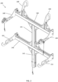
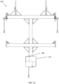
FIGS. 1 and2 are perspective views of an assembly that may be used for mounting an enclosure of a portable remote control locomotive (RCL) system to handrailing of a locomotive. -
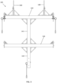
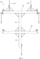
FIGS. 3 and4 are front and back views, respectively, of the assembly shown inFIG. 1 . -
FIGS. 5 and6 are left and right side views, respectively, of the assembly shown inFIG. 1 . -
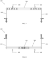
FIGS. 7 and 8 are top and bottom views, respectively, of the assembly shown inFIG. 1 . -
FIGS. 9 and10 are perspective views of the assembly shown inFIG. 1 , and further illustrating an exemplary speaker mounted to the assembly via an exemplary bracket according to an exemplary embodiment. -
FIGS. 11 and12 are front and back views, respectively, of the assembly, speaker, and bracket shown inFIG. 9 . -
FIGS. 13 and14 are left and right side views, respectively, of the assembly, speaker, and bracket shown inFIG. 9 . -
FIGS. 15 and 16 are top and bottom views, respectively, of the assembly, speaker, and bracket shown inFIG. 9 . -
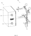
FIG. 17 is a perspective view showing the assembly and the speaker shown in 9.FIG. 17 further illustrates an exemplary enclosure of a portable RCL system that may be mounted to handrailing of a locomotive using the assembly according to an exemplary embodiment. -
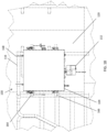
FIGS. 18 and19 illustrates the assembly, the speaker, and the RCL system enclosure shown inFIG. 17 , where the assembly is shown being used for mounting the speaker and the RCL system enclosure to handrailing of a locomotive according to an exemplary embodiment. -
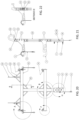
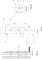
FIG. 20 is a back view of an assembly that may be used for mounting an enclosure of a portable RCL system and a speaker to handrailing of a locomotive according to an exemplary embodiment. -
FIG. 21 is a right side view of the assembly shown inFIG. 20 . -
FIG. 22 is a cross-sectional view taken along the line E-E shown inFIG. 20 . -
FIGS. 23 and 24 are detail views of the portion of the assembly designated A inFIG. 20 . -
FIG. 25 is a detail view of the portion of the assembly designated B inFIG. 20 . -
FIGS. 26 and 27 are cross-sectional views taken along the lines C-C and D-D inFIG. 25 . -
FIG. 28 is a detail view of the portion of the assembly designated F inFIG. 20 . -
FIG. 29 is a cross-sectional view taken along the lines G-G inFIG. 28 . -
FIG. 30 is a detail view of the portion of the assembly designated H inFIG. 20 . -
FIGS. 31 and 32 are cross-sectional views taken along the lines J-J and K-K inFIG. 30 . -
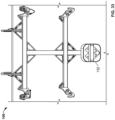
FIG. 33 illustrates an assembly that may be used for mounting a portable RCL system to handrailing of a locomotive.FIG. 33 further illustrates an exemplary speaker mounted to the assembly via an exemplary bracket. -
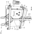
FIGS. 34 and35 illustrate an exemplary portable RCL system including an enclosure mounted onto the assembly shown inFIG. 33 . -
FIG. 36 illustrates the assembly shown inFIG. 33 and the portable RCL system shown inFIGS. 34 and35 mounted to handrailing of a locomotive. -
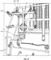
FIG. 37 illustrates the assembly and speaker shown inFIG. 33 mounted to handrailing of a locomotive. -
FIG. 38 illustrates exemplary components of the portable RCL system shown inFIGS. 34 and35 after the enclosure has been opened. -
FIG. 39 illustrates an exemplary outdoor speaker, an audio amplifier, and an audio file player that may be used with an audible alert system according to an exemplary embodiment. The audio amplifier and the audio file player may be internal to a speaker enclosure that is mounted to locomotive handrailing by the assembly shown inFIG. 37 . - The invention is defined by the features of present independent claim 1. Preferred embodiments of the invention are defined by the features of the dependent claims only. The following example embodiments are not necessarily embodiments of the invention.
- Example embodiments will now be described more fully with reference to the accompanying drawings.
- Disclosed are exemplary embodiments of assemblies (e.g., a quick connect mounting cradle assembly, etc.) that may be used for mounting (e.g., without the use of any tools, etc.) enclosures of portable remote control locomotive (RCL) systems and/or speakers to locomotive handrailing. Also disclosed herein portable remote RCL systems mountable to locomotive handrailing by such assemblies. The portable RCL systems may enable rail operators to use handheld remote controllers to remotely control operation (e.g., movement, etc.) of locomotives from remote safe locations with a comprehensive view of each operation.
- In an exemplary embodiment, a mounting assembly (broadly, an assembly) may include one or more adjustable features (e.g., slidably adjustable width top mounting hooks, etc.) that allow or accommodate for mounting to locomotive handrailing having different hand rail configurations. The mounting assembly may be configured as a quick connect mounting assembly that is mountable to locomotive handrailing without the use of any tools. After the mounting assembly is installed to the locomotive handrailing, an enclosure (e.g., of a portable RCL system, etc.) may then be lifted and installed to the assembly without the use of any tools. In this exemplary embodiment, a pair of upper and lower members (e.g., rods, cylindrical members, supports, etc.) may extend outwardly from each of the two opposing sides of the enclosure. The enclosure's upper members and lower members may be configured (e.g., sized, shaped, located, etc.) to be engagingly received, respectively, within portions (e.g., hook shaped portions, etc.) of the upper arms (e.g., pin locking arms, etc.) and lower arms (e.g., lower hooks, etc.) of the mounting assembly. The upper arms of the mounting assembly may comprise two pin locking arms for securing the enclosure to the assembly.
- This exemplary embodiment may generally include two main pieces of hardware, which are the mounting assembly and the enclosure. The mounting assembly and enclosure are configured to allow the enclosure to quick mount to the mounting assembly without the use of any tools. Advantageously, this allows the overall weight to be distributed between these two pieces of hardware, which, in turn, allows for a faster safer installation. For example, the lighter mounting assembly may first be installed to the handrailing of the locomotive without using any tools. The heavier enclosure, including the RCL system components therein (e.g.,
FIG. 38 , etc.), may then be lifted without the additional weight of the previously installed mounting assembly. The enclosure may then be placed on and installed to the mounting assembly without the use of any tools. This exemplary embodiment may thus allow for a fast, safe, easy, and tool-less installation of a portable RCL system to handrailing of a locomotive, while also providing adjustability to account for a wide variety of locomotive handrails and obstructions near the site at which the mounting assembly will be installed. - Also disclosed are audible alert systems. The audible alert system includes an outdoor speaker, an audio amplifier, and an audio file player. The audio amplifier and audio file player may be housed within an environmentally sealed enclosure, which provides protection from the environment.
- The speaker may be located on the front or back of a locomotive. The speaker is mounted to handrailing of a locomotive by using a quick connect mounting assembly disclosed herein. The quick connect mounting assembly may be configured to be mounted to the locomotive handrailing without the use of any tools.
- The audible alert system may be DC (direct current) powered and energy efficient. The speaker may comprise a 100 Watts, 12 volts direct current (VDC) speaker having a relatively thin or slim profile. Alternatively, the audible alert system may include a speaker having a different configuration (e.g., higher or lower than 100 Watts, higher or lower than 12 VDC, etc.).
- Advantageously, the speaker may be lower in weight than and may replace the traditional pneumatic air horn and pneumatic bell currently used on locomotives. The audible alert system, including the speaker, may provide the ability to program multiple sounds and modernize a pneumatic air horn while maintaining overall sound quality. The audio alert system may allow for reduced cost, complexity, and labor to include safety sounding devices onboard locomotives. The audio alert system may also provide integrated audio (voice and tones) and future capabilities to broadcast voice messages.
- With reference now to the figures,
FIGS. 1 through 8 illustrate a quick connect mounting cradle assembly 100 (broadly, an assembly). As shown inFIGS. 17 ,18 ,19 , and36 , theassembly 100 may be used for mounting anenclosure 104 of a portable remote control locomotive (RCL) system 108 (FIG. 38 ) tohandrailing 116 of a locomotive 120. Theassembly 100 may also (FIG. 37 ), be used for mounting aspeaker 132 to thelocomotive handrailing 116. Theportable RCL system 108 is an example only as theassembly 100 may also be used with other portable RCL systems in alternative exemplary embodiments. - With continued reference to
FIGS. 1 and2 , theassembly 100 generally includes upper and lower vertical supports, members, orarms arm 144, and a lower horizontal support, member, orarm 146. By way of example, thearms FIGS. 22 ,26 ,27 , and29 , etc. - The lower
horizontal arm 146 includes opposing upper and lower (or top and bottom) sides that respectively define upper and lower horizontally-extendingslots 147. The upper and lowervertical arms horizontal arm 146 such that the upper and lowervertical arms slots 147. Accordingly, the upper and lowervertical arms horizontal arm 146 depending on the particular handrail configuration and/or the presence of any obstructions near the site at which theassembly 100 will be installed. - The upper
horizontal arm 144 includes opposing upper and lower (or top and bottom) sides that respectively define upper and lower horizontally-extendingslots 145. The uppervertical arm 141 is slidably coupled to the upperhorizontal arm 144 such that the uppervertical arm 141 is horizontally slidable along the lower horizontally-extendingslot 145. Accordingly, the uppervertical arm 141 may be slidably positioned at a center location or at an off-center (e.g., right or left of center, etc.) location along the upperhorizontal arm 144 depending on the particular handrail configuration and/or the presence of any obstructions near the site at which theassembly 100 will be installed. - The sliding adjustability of the
arms assembly 100 will be installed. By way of example, thearms brackets 149,mechanical fasteners 150, and self-aligning T-nuts with ball springs. - Upper hook members 148 (broadly, support members) are respectively coupled (e.g., mechanically fastened, etc.) to opposing end portions of the upper
horizontal arm 144. Lower hook members 152 (broadly, support members) are respectively coupled (e.g., mechanically fastened, etc.) to opposing end portions of the lowerhorizontal arm 146. - Each
upper hook member 148 has a free end portion including or defining ahook 154. A locking bar ormember 156 is pivotably coupled to theupper hook member 148 for pivotable movement relative to thehook 154 between an open position (FIG. 17 ) and a closed position (FIG. 1 ). A pin 158 (e.g., a quick release pin, etc.) is insertable into aligned openings defined by the lockingbar 156 andupper hook member 148 to secure the lockingbar 156 in the closed position. A lanyard 160 (e.g., keyring, cable, and pull-tab, etc.) is coupled to thepin 158 to allow for easier removal of thepin 158 from the aligned openings defined by the lockingbar 156 andupper hook member 148. - Each
lower hook member 152 has a free end portion including or defining ahook 162. As shown inFIGS. 17 ,19 ,34 , and35 , the upper andlower hooks lower members 164, 166 (e.g., rods, cylindrical members, protruding supports, etc.) extending outwardly from opposing sides of theenclosure 104 when theenclosure 104 is mounted or installed onto theassembly 100. - After the
assembly 100 has been installed onto thelocomotive handrailing 116 as disclosed herein, theenclosure 104 may be lifted relative to theassembly 100 to thereby position the enclosure's upper andlower members lower hooks upper members 164 have been engagingly received within the correspondingupper hooks 154, the locking bars 156 may be pivoted relative to thecorresponding hook 154 from the open position to the closed position in which the locking bars 156 are positioned generally over the correspondingupper members 164. Thepins 158 may then be inserted into the aligned openings of thecorresponding locking bar 156 andupper hook member 148 to thereby secure and retain the locking bars 156 in place over theupper members 164, thereby preventing theupper members 156 from being unintentionally removed or dislodged from thehooks 154. - To remove the
enclosure 104 from theassembly 100, eachpin 158 may be removed from the aligned openings of thecorresponding locking bar 156 andupper hook member 148 via thelanyard 160. After thepins 158 have been removed, the locking bars 156 may be pivoted relative to the correspondingupper hook 154 from the closed position to the open position. Thereafter, theenclosure 104 may be lifted upwards relative to theassembly 100 to thereby remove the enclosure's upper andlower members lower hooks - With further reference to
FIGS. 1 and2 , theassembly 100 includes a pair of top mounting hooks 168 configured to be positioned over (e.g., hooked onto, etc.)locomotive handrailing 116. A retainingbar 170 is rotatably coupled to eachhook 168 such that the retainingbar 170 is rotatable between an open position and a closed position (FIG. 1 ). A spring may be provided for biasing the retainingbar 170 in the closed position. In the closed position, the retainingbar 170 may help to secure and retain thehook 168 onto thelocomotive handrailing 116, thereby preventing thehook 168 from being unintentionally unhooked from thelocomotive handrailing 116. - The
hooks 168 are slidably coupled to the upperhorizontal arm 144 such that thehooks 168 are horizontally slidable along the horizontally-extendingslot 145 defined along the top side of the upperhorizontal arm 144. Accordingly, the width between thehooks 168 may be slidably adjusted as thehooks 168 are slidably moved along the upperhorizontal arm 144 closer or farther away from each other depending on the particular handrail configuration and/or presence of any obstructions near the site at which theassembly 100 will be installed. - The sliding width adjustability of the
hooks 168 may thus help to account for a wide variety of locomotive handrails and obstructions near the site at whichassembly 100 will be installed. By way of example, thehooks 168 may be slidably coupled to the upperhorizontal arm 144 usingbrackets 172,mechanical fasteners 174, and self-aligning T-nuts with ball springs. - Also shown in
FIGS. 1 and2 are apin 176 and a lanyard 178 (e.g., keyring, cable, and pull-tab, etc.). Thepin 176 is slidably coupled to the lowervertical arm 142 such that thepin 176 is vertically slidable along the vertically-extendingslots 143 defined by the lowervertical arm 142. Accordingly, thepin 176 may be slidably positioned at various higher or lower locations along the lowervertical arm 142. Thepin 176 andlanyard 178 may be used to tether the lowervertical arm 142 to a railing stanchion on the locomotive 120, which may help prevent theassembly 100 from swinging outwardly away (e.g., forward if mounted on the front of the locomotive, etc.) from the locomotive handrailing during braking and coupling. -
FIGS. 9 through 17 illustrate anexemplary speaker 132 mounted to theassembly 100 via anexemplary speaker bracket 180 according to an exemplary embodiment. Thespeaker 132 is an example only as theassembly 100 may also be used with other speakers in alternative exemplary embodiments. - As shown in
FIG. 1 , the lowervertical arm 142 includes three vertically aligned fastener holes 182. Thus, three mechanical fasteners (e.g., screws, etc.) may be used to couple thespeaker bracket 180 to the lowervertical arm 142. Thespeaker bracket 180 includes four fastener holes 184 (FIG. 12 ) each adjacent a corresponding corner of thespeaker bracket 180. Thus, four mechanical fasteners (e.g., screws, etc.) may be used to couple thespeaker 132 to thespeaker bracket 180. Alternatively, thespeaker bracket 180,speaker 132, and lowervertical arm 142 may be configured differently in other embodiments, such as being configured to be coupled via other means besides mechanical fasteners and/or with more or less mechanical fasteners. - The
speaker 132 may be part of an audible alert system for a locomotive. For example,FIG. 39 illustrates components of an audible alert system according to an exemplary embodiment embodying one or more aspects of the present disclosure. As shown in theFIG. 39 , the audible alert system includes anoutdoor speaker 132, anaudio amplifier 136, and anaudio file player 140 that may be used with an audible alert system. Theaudio amplifier 136 and theaudio file player 140 are housed within an environmentally sealed enclosure, which provides protection from the environment. - The
speaker 132 may be lower in weight than and may replace the traditional pneumatic air horn and pneumatic bell on a locomotive. The audible alert system, including thespeaker 132, may provide the ability to program multiple sounds and modernize a pneumatic air horn while maintaining overall sound quality. Thespeaker 132 may be located on the front or back of a locomotive. Theassembly 100 is used to install thespeaker 132 tolocomotive handrailing 116 on a front of the locomotive 120 as shown inFIGS. 18 ,19 ,36 , and37 . - The audible alert system, including the
speaker 132, may be used with a portable remote control locomotive (RCL) system. For example,FIGS. 34 and35 illustrate an example portable remote control locomotive (RCL)system 108 that may be mounted onto anassembly 100 above thespeaker 132 shown inFIGS. 33 and39 . Theportable RCL system 108 and its components shown inFIG. 38 are examples only as the audible alert system may also be used with other portable RCL systems in alternative exemplary embodiments. - The audible alert system may be direct current (DC) powered and energy efficient. The
speaker 132 may comprise a 100 Watts, 12 volts direct current (VDC) speaker having a relatively thin or slim profile. Alternatively, the audible alert system may include a speaker having a different configuration (e.g., higher or lower than 100 Watts, higher or lower than 12 VDC, etc.). - Advantageously, the audio alert system may allow for reduced cost, complexity, and labor to include safety sounding devices onboard locomotives. The audio alert system may also provide integrated audio (voice and tones) and future capabilities to broadcast voice messages.
-
FIGS. 17 ,18 , and19 illustrate theassembly 100 being used to mount theenclosure 104 of theportable RCL system 108 to thelocomotive handrailing 116. Theportable RCL system 108 andenclosure 104 are examples only as theassembly 100 may also be used with other portable RCL systems and enclosures. -
FIG. 38 illustrates exemplary components of the portable RCL system 108 (FIGS. 34 and35 ) after theenclosure 104 has been opened. By way of example, theenclosure 104 of theportable RCL system 108 may be configured to securely contain the hardware and components of theRCL system 108. Theenclosure 104 may be configured with sufficient ruggedness and durability to withstand and thrive in the harsh environment of rail operations. The outer casing of theenclosure 104 may comprise a durable exterior that protects the components of theportable RCL system 108 from wear and tear. Theportable RCL system 108 may be a lightweight, compact system that houses all hardware and components in thesingle enclosure 104, which may allow for easier troubleshooting and less likelihood of failure. The lightweight, single enclosure system design may also make it physically easier and safer for theportable RCL system 108 to be switched from one locomotive to the other. - In exemplary embodiments, one or more components may include or be provided with (e.g., stamped, etc.) openings to reduce the amount of material, thereby reducing the weight. For example, the
brackets lower hook members 148, 152 (FIGS. 1 and2 ) may include triangular shaped openings to reduce an overall weight of theassembly 100. In addition, thespeaker bracket 180 may also include triangular shaped openings (e.g.,FIGS. 20 and30 , etc.) to reduce an overall weight of theassembly 100. -
FIGS. 20 through 32 illustrate an exemplary embodiment of a quick connect mounting cradle assembly (broadly, an assembly) embodying one or more aspects of the present disclosure. The assembly may be used for mounting an enclosure of a portable remote control locomotive (RCL) system (e.g., portable RCL shown inFIGS. 34-36 and38 , etc.) to handrailing of a locomotive. The assembly may also, or instead, be used for mounting a speaker (e.g., speaker shown inFIGS. 33-37 and39 , etc.) to handrailing of a locomotive. The portable RCL system and speaker shown in the figures are examples only as the assembly shown inFIGS. 20 through 32 may also be used with other portable RCL systems and/or speakers in alternative exemplary embodiments. - In
FIGS. 20 through 32 , items or parts of the assembly are identified with item reference numbers 1 through 32. Table 1 below provides a description for the items or partsTABLE 1 ITEM/PART DESCRIPTION QUANTITY 1 Top Hook 2 2 Bottom Hook 2 3 Lock Bar 2 4 Retaining Bracket 2 5 Speaker Bracket 1 6 Mechanical Fastener 8 8 Spacer 4 9 Locknut, Insert 4 10 Locknut, Insert 2 11 Quick Release Pin, Ring Grip with Lanyard 3 12 Mechanical Fastener 36 13 Self-Aligning T-Nut with Ball Spring 36 15 Mechanical Fastener 2 16 Mechanical Fastener 3 17 Mechanical Fastener 3 20 Mechanical Fastener 10 21 Extrusion with T-Slotted Profile 2 22 Extrusion with T-Slotted Profile 1 24 Bracket, Gusseted Inside Corner, 2 hole 4 25 Bracket, Gusseted Inside Corner, 4 hole 10 26 Extrusion with T-Slotted Profile 1 27 Washer 2 28 Washer 1 29 Washer 2 30 Top Mounting Hook 2 31 Mechanical Fastener 2 32 Mechanical Fastener 2 - Accordingly, exemplary embodiments are disclosed herein of assemblies (e.g., a quick connect mounting cradle assembly, the
assembly 100 shown inFIGS. 1 through 8 , the assembly shown inFIGS. 20 through 32 , etc.) that may be used for mounting (e.g., without the use of any tools, etc.) enclosures of portable RCL systems (e.g.,FIGS. 17-19 ,34-36 , and38 , etc.) optionally also speakers of audible alert systems (e.g.,FIGS. 9-17 ,33-37 , and39 , etc.) to locomotive handrailing. Also disclosed herein are examples of portable remote RCL systems mountable to locomotive handrailing by such assemblies. Additionally, disclosed herein are exemplary embodiments of audible alert systems including speakers mountable to locomotive handrailing by such assemblies. - Exemplary embodiments include systems that include an assembly and a portable RCL system. In such embodiments, the system components are configured such that the assembly is usable for mounting the portable RCL system to locomotive handrailing.
- Exemplary embodiments include systems that include an assembly, a portable RCL system, and a speaker of an audible alert system. In such embodiments, the system components are configured such that the assembly is usable for mounting the portable RCL system and the speaker to locomotive handrailing.
- Also disclosed are exemplary methods of mounting assemblies (e.g., a quick connect mounting cradle assembly, the
assembly 100 shown inFIGS. 1 through 8 , the assembly shown inFIGS. 20 through 32 , etc.) to locomotive handrailing substantially as disclosed herein. In exemplary embodiments, the assembly may comprise a quick connect mounting cradle assembly, and the method may comprise mounting the quick connect mounting cradle assembly to the locomotive handrailing without using any tools. - In exemplary embodiments, the method may comprise mounting the assembly to the locomotive handrailing, and thereafter mounting a portable remote control locomotive system to the assembly previously mounted to the locomotive handrailing.
- The method may comprise mounting the portable remote control locomotive system mounting to the assembly without using any tools.
- The method may further comprise mounting a speaker to the assembly before or after mounting the assembly to the locomotive handrailing.
- The method may comprise mounting a speaker to the assembly; mounting the assembly to the locomotive handrailing without using any tools; and mounting the portable remote control locomotive system to the assembly without using any tools.
- Accordingly, exemplary embodiments disclosed herein may provide or include one or more (but not necessarily any or all) of the following advantages or features, such as installation requiring no tools, mounting hooks that are adjustable for different hand rail configurations, lightweight, compact, fast installation, integrated audio (voice and tones), and/or portability. In exemplary embodiments, quick connect features allow a portable RCL system to be relatively easily and efficiently moved from locomotive to locomotive.
- The portability provided by exemplary embodiments disclosed herein may enable greater flexibility when planning for maintenance and/or allow for less investment or improve rail operators' capital investment by eliminating per locomotive cost requirements. As compared with a traditional fixed mount system, exemplary embodiments disclosed herein may provide an economical solution that shifts upfront capital investments on a per locomotive basis across multiple locomotives giving added financial flexibility.
- With exemplary embodiments disclosed herein, disruption caused by unplanned downtime may be reduced because the assembly and RCL system may be quickly and easily switched from one locomotive to another. For the same reason, it also provides greater flexibility when preparing for planned maintenance.
- Disclosed herein are examples of audible alert systems (e.g., the audible alert system shown in
FIG. 39 , etc.). Exemplary embodiments include systems comprising an audible alert system and a portable RCL system. - Exemplary embodiments include systems comprising an audible alert system and an assembly (e.g., a quick connect mounting assembly, etc.) mountable to handrailing of a locomotive, where the assembly is usable for mounting a speaker of the audible alert system to locomotive handrailing.
- Exemplary embodiments include systems comprising an audible alert system, a portable RCL system, and an assembly mountable to handrailing of a locomotive. In such embodiments, the system components are configured such that the assembly is usable for mounting the portable RCL system and a speaker of the audible alert system to locomotive handrailing.
- Also disclosed are exemplary methods of providing an audible alert system (e.g., the audible alert system shown in
FIG. 39 , etc.) onboard a locomotive. The audible alert system may comprise an outdoor speaker, an audio amplifier, an audio file player, and an enclosure. The audio amplifier and the audio file player may be within the enclosure. - In exemplary embodiments, the method may comprise housing the audio amplifier and the audio file player of the audible alert system within an environmentally sealed enclosure, which provides protection for the audio amplifier and the audio file player from the environment.
- In exemplary embodiments, the enclosure may comprise an environmentally sealed enclosure configured to provide protection for the audio amplifier and the audio file player from the environment. The audible alert system may be configured to be direct current (DC) powered. The speaker comprises a 100 Watts, 12 volts direct current (VDC) speaker. The audible alert system may be configured to provide integrated audio including voices and tones. The audible alert system may be configured to broadcast voice messages.
- In exemplary embodiments, the method may include using the audible alert system instead of and/or as a replacement for a pneumatic air horn and a pneumatic bell onboard the locomotive.
- In exemplary embodiments, the method may include mounting the outdoor speaker of the audible alert system to handrailing of the locomotive. Mounting the speaker of the audible alert system to handrailing of the locomotive may comprise: mounting a quick connect mounting assembly to handrailing of the locomotive without using any tools; and mounting the speaker of the audible alert system to the quick connect mounting assembly before or after mounting the quick connect mounting assembly to the handrailing of the locomotive.
- Example embodiments are provided so that this disclosure will be thorough, and will fully convey the scope to those who are skilled in the art. Numerous specific details are set forth such as examples of specific components, devices, and methods, to provide a thorough understanding of embodiments of the present disclosure. It will be apparent to those skilled in the art that specific details need not be employed, that example embodiments may be embodied in many different forms, and that neither should be construed to limit the scope of the disclosure. In some example embodiments, well-known processes, well-known device structures, and well-known technologies are not described in detail. In addition, advantages and improvements that may be achieved with one or more exemplary embodiments of the present disclosure are provided for purpose of illustration only and do not limit the scope of the present disclosure, as exemplary embodiments disclosed herein may provide all or none of the above mentioned advantages and improvements and still fall within the scope of the present disclosure.
- Specific dimensions, specific materials, and/or specific shapes disclosed herein are example in nature and do not limit the scope of the present disclosure. The disclosure herein of particular values and particular ranges of values for given parameters are not exclusive of other values and ranges of values that may be useful in one or more of the examples disclosed herein. Moreover, it is envisioned that any two particular values for a specific parameter stated herein may define the endpoints of a range of values that may be suitable for the given parameter (i.e., the disclosure of a first value and a second value for a given parameter can be interpreted as disclosing that any value between the first and second values could also be employed for the given parameter). For example, if Parameter X is exemplified herein to have value A and also exemplified to have value Z, it is envisioned that parameter X may have a range of values from about A to about Z. Similarly, it is envisioned that disclosure of two or more ranges of values for a parameter (whether such ranges are nested, overlapping or distinct) subsume all possible combination of ranges for the value that might be claimed using endpoints of the disclosed ranges. For example, if parameter X is exemplified herein to have values in the range of 1 - 10, or 2 - 9, or 3 - 8, it is also envisioned that Parameter X may have other ranges of values including 1 - 9, 1 - 8, 1 - 3, 1 - 2, 2 - 10, 2 - 8, 2 - 3, 3 - 10, and 3 - 9.
- The terminology used herein is for the purpose of describing particular example embodiments only and is not intended to be limiting. For example, when permissive phrases, such as "may comprise", "may include", and the like, are used herein, at least one embodiment comprises or includes the feature(s). As used herein, the singular forms "a", "an" and "the" may be intended to include the plural forms as well, unless the context clearly indicates otherwise. The terms "comprises," "comprising," "including," and "having," are inclusive and therefore specify the presence of stated features, integers, steps, operations, elements, and/or components, but do not preclude the presence or addition of one or more other features, integers, steps, operations, elements, components, and/or groups thereof. The method steps, processes, and operations described herein are not to be construed as necessarily requiring their performance in the particular order discussed or illustrated, unless specifically identified as an order of performance. It is also to be understood that additional or alternative steps may be employed.
- When an element or layer is referred to as being "on", "engaged to", "connected to" or "coupled to" another element or layer, it may be directly on, engaged, connected or coupled to the other element or layer, or intervening elements or layers may be present. In contrast, when an element is referred to as being "directly on," "directly engaged to", "directly connected to" or "directly coupled to" another element or layer, there may be no intervening elements or layers present. Other words used to describe the relationship between elements should be interpreted in a like fashion (e.g., "between" versus "directly between," "adjacent" versus "directly adjacent," etc.). As used herein, the term "and/or" includes any and all combinations of one or more of the associated listed items.
- The term "about" when applied to values indicates that the calculation or the measurement allows some slight imprecision in the value (with some approach to exactness in the value; approximately or reasonably close to the value; nearly). If, for some reason, the imprecision provided by "about" is not otherwise understood in the art with this ordinary meaning, then "about" as used herein indicates at least variations that may arise from ordinary methods of measuring or using such parameters. For example, the terms "generally", "about", and "substantially" may be used herein to mean within manufacturing tolerances.
- Although the terms first, second, third, etc. may be used herein to describe various elements, components, regions, layers and/or sections, these elements, components, regions, layers and/or sections should not be limited by these terms. These terms may be only used to distinguish one element, component, region, layer or section from another region, layer or section. Terms such as "first," "second," and other numerical terms when used herein do not imply a sequence or order unless clearly indicated by the context. Thus, a first element, component, region, layer or section could be termed a second element, component, region, layer or section without departing from the teachings of the example embodiments.
- Spatially relative terms, such as "inner," "outer," "beneath", "below", "lower", "above", "upper" and the like, may be used herein for ease of description to describe one element or feature's relationship to another element(s) or feature(s) as illustrated in the figures. Spatially relative terms may be intended to encompass different orientations of the device in use or operation in addition to the orientation depicted in the figures. For example, if the device in the figures is turned over, elements described as "below" or "beneath" other elements or features would then be oriented "above" the other elements or features. Thus, the example term "below" can encompass both an orientation of above and below. The device may be otherwise oriented (rotated 90 degrees or at other orientations) and the spatially relative descriptors used herein interpreted accordingly.
- The foregoing description of the embodiments has been provided for purposes of illustration and description. It is not intended to be exhaustive or to limit the disclosure. Individual elements, intended or stated uses, or features of a particular embodiment are generally not limited to that particular embodiment, but, where applicable, are interchangeable and can be used in a selected embodiment, even if not specifically shown or described. The same may also be varied in many ways.
Claims (15)
- A method for mounting an enclosure (104),
including components of a remote control locomotive (120) within the enclosure (104), said components being configured to enable rail operators to remotely control an operation of said remote control locomotive (120) by a handheld remote controller,to a locomotive handrailing (116) of the said remote control locomotive (120) without requiring use of tools,said method comprising the steps of:providing a quick connect mounting assembly (100), said quick connect mounting assembly comprising:an upper horizontal arm (144), andfirst and second hooks (168)wherebythe first and second hooks (168) are slidably coupled to the upper horizontal arm (144), andthe first and second hooks (168) are slidable relative to each other along an upper surface of the upper horizontal arm (144) to thereby allow adjustment to a distance separating the first and second hooks (168), andhooking the first and second hooks over and onto the locomotive handrailing (116). - The method of claim 1, wherein said quick connect mounting assembly (100) further comprises an upper vertical arm (141) slidably coupled to the upper horizontal arm (144), whereby the upper vertical arm (141) is horizontally slidable along a lower surface of the upper horizontal arm (144) to thereby allow the upper vertical arm (141) to be slidably positionable at a center location or off-center location along the upper horizontal arm (144).
- The method of claim 2, wherein said quick connect mounting assembly (100) further comprises a lower horizontal arm (146), wherein the upper vertical arm (141) is slidably coupled to the lower horizontal arm (146), whereby the upper vertical arm (141) is horizontally slidable along an upper surface of the lower horizontal arm (146) to thereby allow the upper vertical arm (141) to be slidably positionable at a center location or off-center location along the lower horizontal arm (146).
- The method of claim 3, wherein said quick connect mounting assembly (100) further comprises a lower vertical arm (142) slidably coupled to the lower horizontal arm (146), whereby the lower vertical arm (142) is horizontally slidable along a lower surface of the lower horizontal arm (146) to thereby allow the lower vertical arm (142) to be slidably positionable at a center location or off-center location along the lower horizontal arm (146).
- The method of claim 4, wherein:the upper horizontal arm (144) includes upper and lower horizontally-extending slots (145) along the upper and lower surfaces of the upper horizontal arm (144);the lower horizontal arm (146) includes upper and lower horizontally-extending slots (147) along the upper and lower surfaces of the lower horizontal arm (146);the first and second hooks (168) are horizontally slidable along the upper horizontally-extending slot (145) of the upper horizontal arm (144);the upper vertical arm (141) is horizontally slidable along the lower horizontally-extending slot (145) of the upper horizontal arm (144) and the upper horizontally-extending slot (147) of the lower horizontal arm (146); andthe lower vertical arm (142) is horizontally slidable along the lower horizontally-extending slot (147) of the lower horizontal arm (146).
- The method of claim 4 or 5, wherein the lower vertical arm (142) includes at least one vertically-extending slot (143), and the quick connect mounting assembly (100) further comprises a pin (176) slidably coupled to the lower vertical arm (142) such that the pin (176) is vertically slidable along the at least one vertically-extending slot (143), and a lanyard (178) coupled to the pin (176), whereby the pin (176) and the lanyard (178) are usable for tethering the lower vertical arm (142) to a railing stanchion on the locomotive (120) to inhibit the quick connect mounting assembly (100) from swinging outwardly away from the locomotive handrailing (116) when mounted to the locomotive handrailing (116) during braking and coupling of the remote control locomotive (120).
- The method of any one of claims 2 to 6, wherein said quick connect mounting assembly (100) further comprises first and second upper hook members (148) respectively coupled to opposing first and second end portions of the upper horizontal arm (144), the first upper hook member (148) including a first free end portion including a first upwardly facing hook (154), the second upper hook member (148) including a second free end portion including a second upwardly facing hook (154), the first and second upwardly facing hooks (154) configured to engagingly receive respective first and second upper members (164) extending outwardly from opposing sides of the enclosure (104).
- The method of claim 7, wherein said quick connect mounting assembly (100) further comprises:a first locking member (156) pivotably coupled to the first upper hook member (148) for pivotable movement relative to the first upwardly facing hook (154) between an open position and a closed position;a second locking member (156) pivotably coupled to the second upper hook member (148) for pivotable movement relative to the second upwardly facing hook member (154) between an open position and a closed position;a first pin (158) insertable into aligned openings defined by the first locking member (156) and the first upper hook member (148) to secure the first locking member (156) in the closed position;a second pin (158) insertable into aligned openings defined by the second locking member (156) and the second upper hook member (148) to secure the second locking member (156) in the closed position; anda first lanyard (160) coupled to the first pin (158) to allow for easier removal of the first pin (158) from the aligned openings defined by the first locking member (156) and the first upper hook member (148); anda second lanyard (160) coupled to the second pin (158) to allow for easier removal of the second pin (158) from the aligned openings defined by the second locking member (156) and the second upper hook member (148).
- The method of claim 7 or 8, wherein said quick connect mounting assembly (100) further comprises:first and second lower hook members (152) respectively coupled to opposing first and second end portions of the lower horizontal arm (146), the first lower hook member (152) including a first free end portion including a first upwardly facing hook (162), the second lower hook member (152) including a second free end portion including a second upwardly facing hook (162), the first and second upwardly facing hooks (162) of the first and second lower hook members (152) configured to engagingly receive respective first and second lower members (166) extending outwardly from the opposing sides of the enclosure (104);whereby the enclosure (104) is supported by the quick connect mounting assembly (100) when the first and second upper and lower members (164, 166) of the enclosure (104) are engagingly received respectively within the first and second upwardly facing hooks (154, 162) of the first and second upper and lower hook members (148, 152).
- The method of any one of claims 1 to 9, wherein said quick connect mounting assembly (100) further comprises:a first retaining member (170) rotatably coupled to the first hook (168) such that the first retaining member (170) is rotatable relative to the first hook (168) between an open position in which the first retaining member (170) allows the first hook (168) to be hooked onto or removed from the locomotive handrailing (116), and a closed position in which the first retaining member (170) secures and/or retains the first hook (168) on the locomotive handrailing (116) thereby inhibiting removal of the first hook (168) from the locomotive handrailing (116); anda second retaining member (170) rotatably coupled to the second hook (168) such that the second retaining member (170) is rotatable relative to the second hook (168) between an open position in which the second retaining member (170) allows the second hook (168) to be hooked onto or removed from the locomotive handrailing (116), and a closed position in which the second retaining member (170) secures and/or retains the second hook (168) on the locomotive handrailing (116) thereby inhibiting removal of the second hook (168) from the locomotive handrailing (116).
- The method of any one of claims 1 to 10, wherein the method further comprises
using the quick connect mounting assembly (100) for mounting a speaker (132) to the locomotive handrailing (116). - The method of claim 1, wherein said quick connect mounting assembly (100) further comprises:an upper horizontal arm (144) including opposing upper and lower surfaces;a lower horizontal arm (146) including opposing upper and lower surfaces;an upper vertical arm (141) slidably coupled to the upper and lower horizontal arms (144, 146), whereby the upper vertical arm (141) is horizontally slidable along the lower surface of the upper horizontal arm (144) and the upper surface of the lower horizontal arm (146); anda lower vertical arm (142) slidably coupled to the lower horizontal arm (146), whereby the lower vertical arm (142) is horizontally slidable along the lower surface of the lower horizontal arm (146).
- The method of claim 12, wherein:the upper horizontal arm (144) includes a lower horizontally-extending slot (145) along the lower surface of the upper horizontal arm (144);the lower horizontal arm (146) includes upper and lower horizontally-extending slots (147) along the upper and lower surfaces of the lower horizontal arm (146);the upper vertical arm (141) is horizontally slidable along the lower horizontally-extending slot (145) of the upper horizontal arm (144) and the upper horizontally-extending slot (147) of the lower horizontal arm (146); andthe lower vertical arm (142) is horizontally slidable along the lower horizontally-extending slot (147) of the lower horizontal arm (146).
- The method of claim 12 or 13, wherein said quick connect mounting assembly (100) further comprises:first and second upper hook members (148) respectively coupled to opposing first and second end portions of the upper horizontal arm (144), the first upper hook member (148) including a first free end portion including a first upwardly facing hook (154), the second upper hook member (148) including a second free end portion including a second upwardly facing hook (154), the first and second upwardly facing hooks (154) of the first and second upper hook members (148) configured to engagingly receive respective first and second upper members (164) extending outwardly from opposing sides of the enclosure (104); andfirst and second lower hook members (152) respectively coupled to opposing first and second end portions of the lower horizontal arm (146), the first lower hook member (152) including a first free end portion including a first upwardly facing hook (162), the second lower hook member (152) including a second free end portion including a second upwardly facing hook (162), the first and second upwardly facing hooks (162) of the first and second lower hook members (152) configured to engagingly receive respective first and second lower members (166) extending outwardly from the opposing sides of the enclosure (104);whereby the enclosure (104) is supported by the quick connect mounting assembly (100) when the first and second upper and lower members (164, 168) of the enclosure (104) are engagingly received respectively within the first and second upwardly facing hooks (154, 162) of the first and second upper and lower hook members (148, 152).
- The method of claim 9 or 14, wherein the method comprises:installing the quick connect mounting assembly (100) to the locomotive handrailing (116) without the use of tools prior to installation of the enclosure (104) by hooking the first and second hooks (168) of the quick connect mounting assembly (100) over and onto the locomotive handrailing (116); andinstalling the enclosure (104) to the previously installed quick connect mounting assembly (100) without the use of tools by engagingly receiving the first and second upper and lower members (164, 166) of the enclosure (104) respectively within the first and second upwardly facing hooks (154, 162) of the first and second upper and lower hook members (148, 152).
Priority Applications (1)
| Application Number | Priority Date | Filing Date | Title |
|---|---|---|---|
| EP25181016.4A EP4588723A3 (en) | 2018-08-14 | 2019-08-12 | Method for mounting a portable remote control locomotive systems to a locomotive handrailing |
Applications Claiming Priority (2)
| Application Number | Priority Date | Filing Date | Title |
|---|---|---|---|
| US201862718589P | 2018-08-14 | 2018-08-14 | |
| US16/525,153 US11267491B2 (en) | 2018-08-14 | 2019-07-29 | Assemblies for mounting portable remote control locomotive (RCL) systems to locomotive handrailing |
Related Child Applications (2)
| Application Number | Title | Priority Date | Filing Date |
|---|---|---|---|
| EP25181016.4A Division EP4588723A3 (en) | 2018-08-14 | 2019-08-12 | Method for mounting a portable remote control locomotive systems to a locomotive handrailing |
| EP25181016.4A Previously-Filed-Application EP4588723A3 (en) | 2018-08-14 | 2019-08-12 | Method for mounting a portable remote control locomotive systems to a locomotive handrailing |
Publications (2)
| Publication Number | Publication Date |
|---|---|
| EP3617001A1 EP3617001A1 (en) | 2020-03-04 |
| EP3617001B1 true EP3617001B1 (en) | 2025-06-18 |
Family
ID=67614495
Family Applications (2)
| Application Number | Title | Priority Date | Filing Date |
|---|---|---|---|
| EP19191281.5A Active EP3617001B1 (en) | 2018-08-14 | 2019-08-12 | Method for mounting a portable remote control locomotive systems to a locomotive handrailing |
| EP25181016.4A Pending EP4588723A3 (en) | 2018-08-14 | 2019-08-12 | Method for mounting a portable remote control locomotive systems to a locomotive handrailing |
Family Applications After (1)
| Application Number | Title | Priority Date | Filing Date |
|---|---|---|---|
| EP25181016.4A Pending EP4588723A3 (en) | 2018-08-14 | 2019-08-12 | Method for mounting a portable remote control locomotive systems to a locomotive handrailing |
Country Status (4)
| Country | Link |
|---|---|
| US (1) | US11267491B2 (en) |
| EP (2) | EP3617001B1 (en) |
| CA (1) | CA3051793C (en) |
| DE (1) | DE202019005439U1 (en) |
Families Citing this family (10)
| Publication number | Priority date | Publication date | Assignee | Title |
|---|---|---|---|---|
| USD942322S1 (en) | 2018-08-14 | 2022-02-01 | Cattron North America, Inc. | Assemblies mountable to locomotive handrailing |
| US10766514B2 (en) * | 2018-08-14 | 2020-09-08 | Cattron North America, Inc. | Audible alert systems for locomotives |
| US11267491B2 (en) | 2018-08-14 | 2022-03-08 | Cattron North America, Inc. | Assemblies for mounting portable remote control locomotive (RCL) systems to locomotive handrailing |
| US11525240B2 (en) * | 2020-07-23 | 2022-12-13 | Caterpillar Underground Mining Pty. Ltd. | Storage assembly for battery energizing switches of electric machines |
| DE102020124951A1 (en) * | 2020-09-24 | 2022-03-24 | Markus Schaub | Fastening device for fastening an oxygen concentrator |
| CN112298063B (en) * | 2020-11-02 | 2021-07-02 | 深圳市强鸿电子有限公司 | Vehicle-mounted video recorder stabilizing equipment |
| DE102021200849A1 (en) * | 2021-02-01 | 2022-08-04 | Siemens Mobility GmbH | Attachment for a rail vehicle |
| US12385600B2 (en) | 2022-10-31 | 2025-08-12 | SAFE Structure Designs, LLC | Support apparatus for securing a portable electronic device |
| US12325382B2 (en) * | 2023-03-28 | 2025-06-10 | Donald Dunn | Ladder-mounted storage system |
| US20240367593A1 (en) * | 2023-05-01 | 2024-11-07 | Heath Consultants Incorporated | Vehicle front mounting system and atmospheric sensing assembly |
Family Cites Families (46)
| Publication number | Priority date | Publication date | Assignee | Title |
|---|---|---|---|---|
| US754503A (en) * | 1903-08-31 | 1904-03-15 | John Fred Baxter | Hook-rack. |
| US1219354A (en) * | 1916-02-07 | 1917-03-13 | George Alfred Seward | Lamp-hook for cars. |
| US1294916A (en) * | 1918-05-31 | 1919-02-18 | Alfred Hamilton Knight | Hat-rack. |
| US3208704A (en) * | 1963-11-06 | 1965-09-28 | Michigan Tube Benders Inc | Gas meter mounting bracket |
| US4949068A (en) | 1988-11-28 | 1990-08-14 | John Johnston | Motorcycle sound simulator for a child's toy |
| US4944434A (en) * | 1989-06-30 | 1990-07-31 | Hamilton Kenneth B | Automobile portable hauler |
| US5054732A (en) * | 1989-07-17 | 1991-10-08 | Sukup Eldon R | Intravenous feeder support for stroller |
| US5022538A (en) | 1989-11-28 | 1991-06-11 | Fisher Scientific Company | I.V. bag organizer |
| US5485932A (en) * | 1994-05-03 | 1996-01-23 | Digital Equipment Corporation | Wall mountable modular component mounting system |
| US6079515A (en) | 1995-05-30 | 2000-06-27 | Newman; Ottis G. | Speaker enclosure |
| US6152313A (en) * | 1997-08-20 | 2000-11-28 | Lynk, Inc. | Clothes hanger with sliding hooks |
| US6729485B2 (en) | 1999-04-30 | 2004-05-04 | Glenn Alan Ehrgott | Storage device mounting system |
| US7170396B2 (en) | 2004-06-21 | 2007-01-30 | Simplexgrinnell Lp | Addressable smart speaker |
| DE20013623U1 (en) | 2000-08-08 | 2000-11-23 | Chiang, Chin-Fu, Tainan | Hanger device |
| US6659777B1 (en) | 2000-09-05 | 2003-12-09 | Tammy Rondeau | Automobile activity screen |
| US6450378B1 (en) * | 2000-10-11 | 2002-09-17 | David N. Miller | Portable gun/bow rack |
| US6646548B2 (en) | 2001-01-09 | 2003-11-11 | Whelen Engineering Company, Inc. | Electronic siren |
| US6659412B1 (en) * | 2002-03-19 | 2003-12-09 | Larry C. Roach | Article holder adapted for being supported by a fence |
| DE10239467B4 (en) * | 2002-08-28 | 2006-01-19 | Dräger Medical AG & Co. KGaA | Holding device for utensils on a patient bed |
| US7451708B2 (en) | 2004-03-08 | 2008-11-18 | Qs Industries, Inc. | Sound systems for model railroad locomotives |
| US8515105B2 (en) | 2006-08-29 | 2013-08-20 | The Regents Of The University Of California | System and method for sound generation |
| US8033842B2 (en) | 2006-11-08 | 2011-10-11 | Sony Corporation | Apparatus and method for mounting audio-visual components |
| US8002560B2 (en) | 2006-11-08 | 2011-08-23 | Sony Corporation | Movable audio-visual component system and method |
| US8763971B1 (en) * | 2007-01-16 | 2014-07-01 | Dan Duncan Wilson | Respiratory ventilator transport system |
| US20080169395A1 (en) * | 2007-01-16 | 2008-07-17 | Bullock Charles E | Reconfigurable hook assembly |
| US8028877B2 (en) * | 2008-07-11 | 2011-10-04 | Chien Ping Lien | Connection device for connecting bag to side of bicycle carriage rack |
| US8550315B2 (en) | 2008-10-24 | 2013-10-08 | Chrysler Group Llc | Spare tire carrier vibration damper |
| US20100127028A1 (en) | 2008-11-26 | 2010-05-27 | Michael Lusk | Article holder mountable to container of wheelbarrow |
| US9085306B2 (en) | 2009-06-24 | 2015-07-21 | Union Pacific Railroad Company | Drag reducing devices for a locomotive |
| EP2295303B1 (en) | 2009-09-11 | 2012-02-01 | S.I.T.F.A. - Società Italiana Trasporti Ferroviari Autoveicoli S.p.A. | Railway car for carrying motor-vehicles |
| US8251331B2 (en) * | 2010-11-29 | 2012-08-28 | Robert B Fowler | Article holder adapted for being supported by a fence |
| WO2013028840A1 (en) | 2011-08-23 | 2013-02-28 | Sygnet Rail Technologies, Llc | Apparatus and method for power production, control, and/or telematics, suitable for use with locomotives |
| US8479930B1 (en) | 2012-01-12 | 2013-07-09 | Joshua C. Cohen | Organizing system for weights and accessories |
| US8910417B1 (en) | 2012-07-14 | 2014-12-16 | Douglas Reid Meyers | Cut flower container |
| WO2014028972A1 (en) | 2012-08-22 | 2014-02-27 | Nfa Innovations Pty Ltd | An apparatus for radio break-in |
| WO2015024092A1 (en) | 2013-08-21 | 2015-02-26 | Vista Acquisitions Inc. | Audio systems for generating sound on personal watercraft and other recreational vehicles |
| DE202014100932U1 (en) * | 2014-01-28 | 2014-03-27 | Accuride International Gmbh | Quick-fastening element and guide rail |
| US9440661B2 (en) | 2014-03-06 | 2016-09-13 | Siemens Industry, Inc. | Integrated ceiling assembly for railcars |
| RU2544778C1 (en) | 2014-04-18 | 2015-03-20 | Открытое акционерное общество "Научно-исследовательский и проектно-конструкторский институт информатизации, автоматизации и связи на железнодорожном транспорте" (ОАО "НИИАС") | Apparatus for alerting workers on railway tracks at station on approaching rolling stock |
| US9663173B2 (en) * | 2014-08-19 | 2017-05-30 | Brian Wadey | Mounting device for one or more accessories and method of using same |
| US10023210B2 (en) | 2015-02-06 | 2018-07-17 | Laird Technologies, Inc. | Devices, systems, and methods related to tracking location of operator control units for locomotives |
| US9718405B1 (en) | 2015-03-23 | 2017-08-01 | Rosco, Inc. | Collision avoidance and/or pedestrian detection system |
| DE202017100219U1 (en) * | 2017-01-17 | 2018-04-18 | Adam Hall Gmbh | Fixing system for a housing, in particular a loudspeaker |
| US10780362B2 (en) | 2017-07-25 | 2020-09-22 | Ring Engineering, Inc. | Method and an apparatus to improve the realism of a model locomotive motion and sounds |
| US10766514B2 (en) * | 2018-08-14 | 2020-09-08 | Cattron North America, Inc. | Audible alert systems for locomotives |
| US11267491B2 (en) | 2018-08-14 | 2022-03-08 | Cattron North America, Inc. | Assemblies for mounting portable remote control locomotive (RCL) systems to locomotive handrailing |
-
2019
- 2019-07-29 US US16/525,153 patent/US11267491B2/en active Active
- 2019-08-12 EP EP19191281.5A patent/EP3617001B1/en active Active
- 2019-08-12 EP EP25181016.4A patent/EP4588723A3/en active Pending
- 2019-08-12 CA CA3051793A patent/CA3051793C/en active Active
- 2019-08-12 DE DE202019005439.1U patent/DE202019005439U1/en active Active
Also Published As
| Publication number | Publication date |
|---|---|
| US20200055527A1 (en) | 2020-02-20 |
| EP4588723A2 (en) | 2025-07-23 |
| CA3051793C (en) | 2022-04-26 |
| EP4588723A3 (en) | 2025-09-24 |
| US11267491B2 (en) | 2022-03-08 |
| EP3617001A1 (en) | 2020-03-04 |
| DE202019005439U1 (en) | 2020-09-28 |
| CA3051793A1 (en) | 2020-02-14 |
Similar Documents
| Publication | Publication Date | Title |
|---|---|---|
| EP3617001B1 (en) | Method for mounting a portable remote control locomotive systems to a locomotive handrailing | |
| US9038315B2 (en) | Self-balancing double-hung window apparatus | |
| US6698138B1 (en) | Adjustable pulley assembly for a suspended door | |
| US8104651B2 (en) | Vehicle roof rack end support | |
| CA2612100C (en) | Tool for positioning molding | |
| WO2007006827A3 (en) | Continuous metal system for safety barriers, which is intended to protect motorcyclists and which comprises a lower continuous horizontal metal panel which is supported by the barrier by means of regularly-spaced metal arms | |
| EP3611072B1 (en) | Audible alert system and method for locomotives | |
| JP5052927B2 (en) | Rollaway bed equipment | |
| US20230284798A1 (en) | Merchandise access gate and retail merchandise display including merchandise access gate | |
| EP1034727B1 (en) | System for adjustably mounting an item to a verticle surface | |
| EP2310131B1 (en) | A granulator housing and a method for mounting/dismounting a knife therein | |
| US10052779B2 (en) | Waterjet safety enclosure system | |
| US20080203261A1 (en) | Barn door roller/adjustment | |
| CN223881499U (en) | A quick assembly accessory for industrial aluminum profiles | |
| US6904625B1 (en) | Auxiliary spa module | |
| US10473342B1 (en) | Davit system for servicing an air conditioning unit | |
| GB2528379A (en) | Panel apparatus and method of use thereof | |
| CN111878678A (en) | Fixing device for monitoring camera | |
| US20250354434A1 (en) | Secure delivery door kit | |
| CN208830814U (en) | monitoring facility | |
| KR200449536Y1 (en) | Fixture for Window Installation | |
| CN208947269U (en) | A kind of passenger seat acoustic alarm wiring harness protection device | |
| KR20140136770A (en) | A driver-protecter for a car | |
| CN101708705A (en) | Safe antitheft frame for automobile license tag | |
| JPH084403A (en) | Hanging hook with roller |
Legal Events
| Date | Code | Title | Description |
|---|---|---|---|
| PUAI | Public reference made under article 153(3) epc to a published international application that has entered the european phase |
Free format text: ORIGINAL CODE: 0009012 |
|
| STAA | Information on the status of an ep patent application or granted ep patent |
Free format text: STATUS: THE APPLICATION HAS BEEN PUBLISHED |
|
| AK | Designated contracting states |
Kind code of ref document: A1 Designated state(s): AL AT BE BG CH CY CZ DE DK EE ES FI FR GB GR HR HU IE IS IT LI LT LU LV MC MK MT NL NO PL PT RO RS SE SI SK SM TR |
|
| AX | Request for extension of the european patent |
Extension state: BA ME |
|
| STAA | Information on the status of an ep patent application or granted ep patent |
Free format text: STATUS: REQUEST FOR EXAMINATION WAS MADE |
|
| 17P | Request for examination filed |
Effective date: 20200508 |
|
| RBV | Designated contracting states (corrected) |
Designated state(s): AL AT BE BG CH CY CZ DE DK EE ES FI FR GB GR HR HU IE IS IT LI LT LU LV MC MK MT NL NO PL PT RO RS SE SI SK SM TR |
|
| STAA | Information on the status of an ep patent application or granted ep patent |
Free format text: STATUS: EXAMINATION IS IN PROGRESS |
|
| 17Q | First examination report despatched |
Effective date: 20220419 |
|
| GRAP | Despatch of communication of intention to grant a patent |
Free format text: ORIGINAL CODE: EPIDOSNIGR1 |
|
| STAA | Information on the status of an ep patent application or granted ep patent |
Free format text: STATUS: GRANT OF PATENT IS INTENDED |
|
| INTG | Intention to grant announced |
Effective date: 20250402 |
|
| GRAS | Grant fee paid |
Free format text: ORIGINAL CODE: EPIDOSNIGR3 |
|
| GRAA | (expected) grant |
Free format text: ORIGINAL CODE: 0009210 |
|
| STAA | Information on the status of an ep patent application or granted ep patent |
Free format text: STATUS: THE PATENT HAS BEEN GRANTED |
|
| AK | Designated contracting states |
Kind code of ref document: B1 Designated state(s): AL AT BE BG CH CY CZ DE DK EE ES FI FR GB GR HR HU IE IS IT LI LT LU LV MC MK MT NL NO PL PT RO RS SE SI SK SM TR |
|
| REG | Reference to a national code |
Ref country code: GB Ref legal event code: FG4D |
|
| REG | Reference to a national code |
Ref country code: CH Ref legal event code: EP |
|
| REG | Reference to a national code |
Ref country code: DE Ref legal event code: R096 Ref document number: 602019071178 Country of ref document: DE |
|
| REG | Reference to a national code |
Ref country code: CH Ref legal event code: EP |
|
| REG | Reference to a national code |
Ref country code: IE Ref legal event code: FG4D |
|
| PG25 | Lapsed in a contracting state [announced via postgrant information from national office to epo] |
Ref country code: FI Free format text: LAPSE BECAUSE OF FAILURE TO SUBMIT A TRANSLATION OF THE DESCRIPTION OR TO PAY THE FEE WITHIN THE PRESCRIBED TIME-LIMIT Effective date: 20250618 |
|
| REG | Reference to a national code |
Ref country code: LT Ref legal event code: MG9D |
|
| PG25 | Lapsed in a contracting state [announced via postgrant information from national office to epo] |
Ref country code: NO Free format text: LAPSE BECAUSE OF FAILURE TO SUBMIT A TRANSLATION OF THE DESCRIPTION OR TO PAY THE FEE WITHIN THE PRESCRIBED TIME-LIMIT Effective date: 20250918 Ref country code: GR Free format text: LAPSE BECAUSE OF FAILURE TO SUBMIT A TRANSLATION OF THE DESCRIPTION OR TO PAY THE FEE WITHIN THE PRESCRIBED TIME-LIMIT Effective date: 20250919 |
|
| PG25 | Lapsed in a contracting state [announced via postgrant information from national office to epo] |
Ref country code: BG Free format text: LAPSE BECAUSE OF FAILURE TO SUBMIT A TRANSLATION OF THE DESCRIPTION OR TO PAY THE FEE WITHIN THE PRESCRIBED TIME-LIMIT Effective date: 20250618 |
|
| PG25 | Lapsed in a contracting state [announced via postgrant information from national office to epo] |
Ref country code: HR Free format text: LAPSE BECAUSE OF FAILURE TO SUBMIT A TRANSLATION OF THE DESCRIPTION OR TO PAY THE FEE WITHIN THE PRESCRIBED TIME-LIMIT Effective date: 20250618 |
|
| PG25 | Lapsed in a contracting state [announced via postgrant information from national office to epo] |
Ref country code: RS Free format text: LAPSE BECAUSE OF FAILURE TO SUBMIT A TRANSLATION OF THE DESCRIPTION OR TO PAY THE FEE WITHIN THE PRESCRIBED TIME-LIMIT Effective date: 20250918 |
|
| REG | Reference to a national code |
Ref country code: NL Ref legal event code: MP Effective date: 20250618 |
|
| PG25 | Lapsed in a contracting state [announced via postgrant information from national office to epo] |
Ref country code: LV Free format text: LAPSE BECAUSE OF FAILURE TO SUBMIT A TRANSLATION OF THE DESCRIPTION OR TO PAY THE FEE WITHIN THE PRESCRIBED TIME-LIMIT Effective date: 20250618 |
|
| PG25 | Lapsed in a contracting state [announced via postgrant information from national office to epo] |
Ref country code: NL Free format text: LAPSE BECAUSE OF FAILURE TO SUBMIT A TRANSLATION OF THE DESCRIPTION OR TO PAY THE FEE WITHIN THE PRESCRIBED TIME-LIMIT Effective date: 20250618 |
|
| PG25 | Lapsed in a contracting state [announced via postgrant information from national office to epo] |
Ref country code: PT Free format text: LAPSE BECAUSE OF FAILURE TO SUBMIT A TRANSLATION OF THE DESCRIPTION OR TO PAY THE FEE WITHIN THE PRESCRIBED TIME-LIMIT Effective date: 20251020 |
|
| REG | Reference to a national code |
Ref country code: AT Ref legal event code: MK05 Ref document number: 1803926 Country of ref document: AT Kind code of ref document: T Effective date: 20250618 |
|
| PG25 | Lapsed in a contracting state [announced via postgrant information from national office to epo] |
Ref country code: IS Free format text: LAPSE BECAUSE OF FAILURE TO SUBMIT A TRANSLATION OF THE DESCRIPTION OR TO PAY THE FEE WITHIN THE PRESCRIBED TIME-LIMIT Effective date: 20251018 |
|
| PG25 | Lapsed in a contracting state [announced via postgrant information from national office to epo] |
Ref country code: AT Free format text: LAPSE BECAUSE OF FAILURE TO SUBMIT A TRANSLATION OF THE DESCRIPTION OR TO PAY THE FEE WITHIN THE PRESCRIBED TIME-LIMIT Effective date: 20250618 Ref country code: SM Free format text: LAPSE BECAUSE OF FAILURE TO SUBMIT A TRANSLATION OF THE DESCRIPTION OR TO PAY THE FEE WITHIN THE PRESCRIBED TIME-LIMIT Effective date: 20250618 |
|
| PG25 | Lapsed in a contracting state [announced via postgrant information from national office to epo] |
Ref country code: CZ Free format text: LAPSE BECAUSE OF FAILURE TO SUBMIT A TRANSLATION OF THE DESCRIPTION OR TO PAY THE FEE WITHIN THE PRESCRIBED TIME-LIMIT Effective date: 20250618 |
|
| PG25 | Lapsed in a contracting state [announced via postgrant information from national office to epo] |
Ref country code: PL Free format text: LAPSE BECAUSE OF FAILURE TO SUBMIT A TRANSLATION OF THE DESCRIPTION OR TO PAY THE FEE WITHIN THE PRESCRIBED TIME-LIMIT Effective date: 20250618 |
|
| PG25 | Lapsed in a contracting state [announced via postgrant information from national office to epo] |
Ref country code: EE Free format text: LAPSE BECAUSE OF FAILURE TO SUBMIT A TRANSLATION OF THE DESCRIPTION OR TO PAY THE FEE WITHIN THE PRESCRIBED TIME-LIMIT Effective date: 20250618 |
|
| PG25 | Lapsed in a contracting state [announced via postgrant information from national office to epo] |
Ref country code: RO Free format text: LAPSE BECAUSE OF FAILURE TO SUBMIT A TRANSLATION OF THE DESCRIPTION OR TO PAY THE FEE WITHIN THE PRESCRIBED TIME-LIMIT Effective date: 20250618 Ref country code: SK Free format text: LAPSE BECAUSE OF FAILURE TO SUBMIT A TRANSLATION OF THE DESCRIPTION OR TO PAY THE FEE WITHIN THE PRESCRIBED TIME-LIMIT Effective date: 20250618 |
|
| PG25 | Lapsed in a contracting state [announced via postgrant information from national office to epo] |
Ref country code: ES Free format text: LAPSE BECAUSE OF FAILURE TO SUBMIT A TRANSLATION OF THE DESCRIPTION OR TO PAY THE FEE WITHIN THE PRESCRIBED TIME-LIMIT Effective date: 20250618 |
|
| REG | Reference to a national code |
Ref country code: DE Ref legal event code: R119 Ref document number: 602019071178 Country of ref document: DE |
|
| REG | Reference to a national code |
Ref country code: CH Ref legal event code: H13 Free format text: ST27 STATUS EVENT CODE: U-0-0-H10-H13 (AS PROVIDED BY THE NATIONAL OFFICE) Effective date: 20260324 |
|
| PG25 | Lapsed in a contracting state [announced via postgrant information from national office to epo] |
Ref country code: MC Free format text: LAPSE BECAUSE OF FAILURE TO SUBMIT A TRANSLATION OF THE DESCRIPTION OR TO PAY THE FEE WITHIN THE PRESCRIBED TIME-LIMIT Effective date: 20250618 |
|
| PG25 | Lapsed in a contracting state [announced via postgrant information from national office to epo] |
Ref country code: DK Free format text: LAPSE BECAUSE OF FAILURE TO SUBMIT A TRANSLATION OF THE DESCRIPTION OR TO PAY THE FEE WITHIN THE PRESCRIBED TIME-LIMIT Effective date: 20250618 |
|
| PG25 | Lapsed in a contracting state [announced via postgrant information from national office to epo] |
Ref country code: LU Free format text: LAPSE BECAUSE OF NON-PAYMENT OF DUE FEES Effective date: 20250812 Ref country code: IT Free format text: LAPSE BECAUSE OF FAILURE TO SUBMIT A TRANSLATION OF THE DESCRIPTION OR TO PAY THE FEE WITHIN THE PRESCRIBED TIME-LIMIT Effective date: 20250618 |
|
| PG25 | Lapsed in a contracting state [announced via postgrant information from national office to epo] |
Ref country code: CH Free format text: LAPSE BECAUSE OF NON-PAYMENT OF DUE FEES Effective date: 20250831 |
|
| PLBE | No opposition filed within time limit |
Free format text: ORIGINAL CODE: 0009261 |
|
| STAA | Information on the status of an ep patent application or granted ep patent |
Free format text: STATUS: NO OPPOSITION FILED WITHIN TIME LIMIT |
|
| REG | Reference to a national code |
Ref country code: CH Ref legal event code: L10 Free format text: ST27 STATUS EVENT CODE: U-0-0-L10-L00 (AS PROVIDED BY THE NATIONAL OFFICE) Effective date: 20260430 |