EP3616981A1 - Vehicle seat - Google Patents
Vehicle seat Download PDFInfo
- Publication number
- EP3616981A1 EP3616981A1 EP19192632.8A EP19192632A EP3616981A1 EP 3616981 A1 EP3616981 A1 EP 3616981A1 EP 19192632 A EP19192632 A EP 19192632A EP 3616981 A1 EP3616981 A1 EP 3616981A1
- Authority
- EP
- European Patent Office
- Prior art keywords
- seat
- vehicle
- vehicle seat
- seat cushion
- surface portion
- Prior art date
- Legal status (The legal status is an assumption and is not a legal conclusion. Google has not performed a legal analysis and makes no representation as to the accuracy of the status listed.)
- Granted
Links
Images


Classifications
-
- B—PERFORMING OPERATIONS; TRANSPORTING
- B60—VEHICLES IN GENERAL
- B60N—SEATS SPECIALLY ADAPTED FOR VEHICLES; VEHICLE PASSENGER ACCOMMODATION NOT OTHERWISE PROVIDED FOR
- B60N2/00—Seats specially adapted for vehicles; Arrangement or mounting of seats in vehicles
- B60N2/24—Seats specially adapted for vehicles; Arrangement or mounting of seats in vehicles for particular purposes or particular vehicles
- B60N2/42—Seats specially adapted for vehicles; Arrangement or mounting of seats in vehicles for particular purposes or particular vehicles the seat constructed to protect the occupant from the effect of abnormal g-forces, e.g. crash or safety seats
- B60N2/4207—Seats specially adapted for vehicles; Arrangement or mounting of seats in vehicles for particular purposes or particular vehicles the seat constructed to protect the occupant from the effect of abnormal g-forces, e.g. crash or safety seats characterised by the direction of the g-forces
- B60N2/4214—Seats specially adapted for vehicles; Arrangement or mounting of seats in vehicles for particular purposes or particular vehicles the seat constructed to protect the occupant from the effect of abnormal g-forces, e.g. crash or safety seats characterised by the direction of the g-forces longitudinal
- B60N2/4228—Seats specially adapted for vehicles; Arrangement or mounting of seats in vehicles for particular purposes or particular vehicles the seat constructed to protect the occupant from the effect of abnormal g-forces, e.g. crash or safety seats characterised by the direction of the g-forces longitudinal due to impact coming from the rear
-
- B—PERFORMING OPERATIONS; TRANSPORTING
- B60—VEHICLES IN GENERAL
- B60R—VEHICLES, VEHICLE FITTINGS, OR VEHICLE PARTS, NOT OTHERWISE PROVIDED FOR
- B60R21/00—Arrangements or fittings on vehicles for protecting or preventing injuries to occupants or pedestrians in case of accidents or other traffic risks
- B60R21/02—Occupant safety arrangements or fittings, e.g. crash pads
- B60R21/16—Inflatable occupant restraints or confinements designed to inflate upon impact or impending impact, e.g. air bags
- B60R21/23—Inflatable members
- B60R21/231—Inflatable members characterised by their shape, construction or spatial configuration
- B60R21/23138—Inflatable members characterised by their shape, construction or spatial configuration specially adapted for side protection
-
- B—PERFORMING OPERATIONS; TRANSPORTING
- B60—VEHICLES IN GENERAL
- B60N—SEATS SPECIALLY ADAPTED FOR VEHICLES; VEHICLE PASSENGER ACCOMMODATION NOT OTHERWISE PROVIDED FOR
- B60N2/00—Seats specially adapted for vehicles; Arrangement or mounting of seats in vehicles
- B60N2/24—Seats specially adapted for vehicles; Arrangement or mounting of seats in vehicles for particular purposes or particular vehicles
- B60N2/42—Seats specially adapted for vehicles; Arrangement or mounting of seats in vehicles for particular purposes or particular vehicles the seat constructed to protect the occupant from the effect of abnormal g-forces, e.g. crash or safety seats
- B60N2/427—Seats or parts thereof displaced during a crash
- B60N2/42709—Seats or parts thereof displaced during a crash involving residual deformation or fracture of the structure
-
- B—PERFORMING OPERATIONS; TRANSPORTING
- B60—VEHICLES IN GENERAL
- B60N—SEATS SPECIALLY ADAPTED FOR VEHICLES; VEHICLE PASSENGER ACCOMMODATION NOT OTHERWISE PROVIDED FOR
- B60N2/00—Seats specially adapted for vehicles; Arrangement or mounting of seats in vehicles
- B60N2/24—Seats specially adapted for vehicles; Arrangement or mounting of seats in vehicles for particular purposes or particular vehicles
- B60N2/42—Seats specially adapted for vehicles; Arrangement or mounting of seats in vehicles for particular purposes or particular vehicles the seat constructed to protect the occupant from the effect of abnormal g-forces, e.g. crash or safety seats
- B60N2/427—Seats or parts thereof displaced during a crash
- B60N2/42727—Seats or parts thereof displaced during a crash involving substantially rigid displacement
- B60N2/42754—Seats or parts thereof displaced during a crash involving substantially rigid displacement of the cushion
- B60N2/42763—Seats or parts thereof displaced during a crash involving substantially rigid displacement of the cushion with anti-submarining systems
-
- B—PERFORMING OPERATIONS; TRANSPORTING
- B60—VEHICLES IN GENERAL
- B60N—SEATS SPECIALLY ADAPTED FOR VEHICLES; VEHICLE PASSENGER ACCOMMODATION NOT OTHERWISE PROVIDED FOR
- B60N2/00—Seats specially adapted for vehicles; Arrangement or mounting of seats in vehicles
- B60N2/24—Seats specially adapted for vehicles; Arrangement or mounting of seats in vehicles for particular purposes or particular vehicles
- B60N2/42—Seats specially adapted for vehicles; Arrangement or mounting of seats in vehicles for particular purposes or particular vehicles the seat constructed to protect the occupant from the effect of abnormal g-forces, e.g. crash or safety seats
- B60N2/427—Seats or parts thereof displaced during a crash
- B60N2/42772—Seats or parts thereof displaced during a crash characterised by the triggering system
- B60N2/4279—Seats or parts thereof displaced during a crash characterised by the triggering system electric or electronic triggering
-
- B—PERFORMING OPERATIONS; TRANSPORTING
- B60—VEHICLES IN GENERAL
- B60N—SEATS SPECIALLY ADAPTED FOR VEHICLES; VEHICLE PASSENGER ACCOMMODATION NOT OTHERWISE PROVIDED FOR
- B60N2/00—Seats specially adapted for vehicles; Arrangement or mounting of seats in vehicles
- B60N2/68—Seat frames
- B60N2/686—Panel like structures
-
- B—PERFORMING OPERATIONS; TRANSPORTING
- B60—VEHICLES IN GENERAL
- B60N—SEATS SPECIALLY ADAPTED FOR VEHICLES; VEHICLE PASSENGER ACCOMMODATION NOT OTHERWISE PROVIDED FOR
- B60N2/00—Seats specially adapted for vehicles; Arrangement or mounting of seats in vehicles
- B60N2/70—Upholstery springs ; Upholstery
-
- B—PERFORMING OPERATIONS; TRANSPORTING
- B60—VEHICLES IN GENERAL
- B60R—VEHICLES, VEHICLE FITTINGS, OR VEHICLE PARTS, NOT OTHERWISE PROVIDED FOR
- B60R21/00—Arrangements or fittings on vehicles for protecting or preventing injuries to occupants or pedestrians in case of accidents or other traffic risks
- B60R21/02—Occupant safety arrangements or fittings, e.g. crash pads
- B60R21/055—Padded or energy-absorbing fittings, e.g. seat belt anchors
-
- B—PERFORMING OPERATIONS; TRANSPORTING
- B60—VEHICLES IN GENERAL
- B60R—VEHICLES, VEHICLE FITTINGS, OR VEHICLE PARTS, NOT OTHERWISE PROVIDED FOR
- B60R21/00—Arrangements or fittings on vehicles for protecting or preventing injuries to occupants or pedestrians in case of accidents or other traffic risks
- B60R21/02—Occupant safety arrangements or fittings, e.g. crash pads
- B60R21/16—Inflatable occupant restraints or confinements designed to inflate upon impact or impending impact, e.g. air bags
- B60R21/20—Arrangements for storing inflatable members in their non-use or deflated condition; Arrangement or mounting of air bag modules or components
- B60R21/207—Arrangements for storing inflatable members in their non-use or deflated condition; Arrangement or mounting of air bag modules or components in vehicle seats
-
- B—PERFORMING OPERATIONS; TRANSPORTING
- B60—VEHICLES IN GENERAL
- B60N—SEATS SPECIALLY ADAPTED FOR VEHICLES; VEHICLE PASSENGER ACCOMMODATION NOT OTHERWISE PROVIDED FOR
- B60N2/00—Seats specially adapted for vehicles; Arrangement or mounting of seats in vehicles
- B60N2/58—Seat coverings
- B60N2002/5808—Seat coverings comprising opening zones for airbags
-
- B—PERFORMING OPERATIONS; TRANSPORTING
- B60—VEHICLES IN GENERAL
- B60R—VEHICLES, VEHICLE FITTINGS, OR VEHICLE PARTS, NOT OTHERWISE PROVIDED FOR
- B60R21/00—Arrangements or fittings on vehicles for protecting or preventing injuries to occupants or pedestrians in case of accidents or other traffic risks
- B60R2021/003—Arrangements or fittings on vehicles for protecting or preventing injuries to occupants or pedestrians in case of accidents or other traffic risks characterised by occupant or pedestian
- B60R2021/0039—Body parts of the occupant or pedestrian affected by the accident
- B60R2021/0053—Legs
-
- B—PERFORMING OPERATIONS; TRANSPORTING
- B60—VEHICLES IN GENERAL
- B60R—VEHICLES, VEHICLE FITTINGS, OR VEHICLE PARTS, NOT OTHERWISE PROVIDED FOR
- B60R21/00—Arrangements or fittings on vehicles for protecting or preventing injuries to occupants or pedestrians in case of accidents or other traffic risks
- B60R21/02—Occupant safety arrangements or fittings, e.g. crash pads
- B60R21/16—Inflatable occupant restraints or confinements designed to inflate upon impact or impending impact, e.g. air bags
- B60R21/23—Inflatable members
- B60R21/231—Inflatable members characterised by their shape, construction or spatial configuration
- B60R2021/23176—Inflatable members characterised by their shape, construction or spatial configuration specially adapted for foot protection
Definitions
- the present disclosure relates to a vehicle seat.
- JP-A No. 2017-149331 discloses a passenger protecting device that reduces the injury degree of passengers who are seated in vehicle seats that are disposed so as to face one another in the front-rear direction of a vehicle.
- the passenger protecting device disclosed in that document at the time of a collision of the vehicle, by expanding a traversing airbag between vehicle seats that are disposed so as to face one another, the traversing airbag is interposed between the passengers who are seated in these vehicle seats. Due thereto, the knees of the passengers who are seated in the vehicle seats contacting one another can be suppressed.
- an object of the present disclosure is to provide a vehicle seat that can reduce the injury degree of the calves of the legs of a passenger at the time of a collision that is such that the calves are pushed against a distal end portion of a seat cushion.
- a vehicle seat of a first aspect of the present disclosure has a seat cushion and a seat back, and the vehicle seat further has a front surface portion that structure a portion of a frame of the seat cushion, which is adapted to support buttocks of a passenger, the front surface portion is disposed at a front part of the vehicle seat, and a face of the front surface portion facing toward a front side of the vehicle seat; and an energy absorbing member that is provided along the face of the front surface portion, and, that is configured to irreversibly deform by being pushed toward a rear side of the vehicle seat.
- the energy absorbing member is pushed by the legs of the passenger.
- the energy absorbing member irreversibly deforms, between the legs of the passenger and the front surface portion of the frame of the seat cushion. As a result, the injury degree of the calves of the legs of the passenger can be reduced.
- a seat cushion pad is mounted to the frame of the seat cushion, and the energy absorbing member is formed integrally with the seat cushion pad.
- the energy absorbing member is formed integrally with the seat cushion pad. Due thereto, the mounting of the energy absorbing member can be completed simultaneously with the work of mounting the seat cushion pad to the frame of the seat cushion.
- the energy absorbing member is fixed to the face of the front surface portion.
- the energy absorbing member is fixed to the face of the front surface portion of the frame of the seat cushion. Due thereto, the mounted posture of the energy absorbing member with respect to the frame of the seat cushion can be stabilized.
- the energy absorbing member is an airbag that inflates in a case in which the passenger inertially moves toward a rear side of the vehicle seat, and at least a portion of the airbag after inflation is disposed along the face of the front surface portion.
- the airbag inflates at the time when the vehicle collides at a front side thereof in a state in which the vehicle seat is facing toward the rear side of the vehicle, or at the time when the vehicle collides at a rear side thereof in a state in which the vehicle seat is facing toward the front side of the vehicle, i.e., at the time when the passenger inertially moves toward the rear side of the vehicle seat.
- the airbag is pushed by the legs of the passenger. Due thereto, the airbag irreversibly deforms, between the legs of the passenger and the front surface portion of the frame of the seat cushion. As a result, the injury degree of the calves of the legs of the passenger can be reduced.
- a seat cushion pad is mounted to the frame of the seat cushion, the airbag is disposed between the frame of the seat cushion and the seat cushion pad, and a portion at a seat front side of the seat cushion pad is configured to inflate toward a seat upper side due to the airbag inflating.
- the portion at the seat front side of the seat cushion pad bulges toward the seat upper side.
- the airbag being inflated in a case in which the passenger inertially moves toward the front side of the vehicle seat, the buttocks of the passenger can be restrained by the front end portion of the seat cushion pad.
- the airbag being inflated in a case in which the passenger inertially moves toward the rear side of the vehicle seat, the airbag is pushed by the legs of the passenger and the injury degree of the calves of the legs of the passenger can be reduced.
- the vehicle seats of the respective aspects of the present disclosure have the excellent effect of being able to reduce the injury degree of the calves of the legs of a passenger at the time of a collision which is such that the calves are pushed-against the distal end portion of a seat cushion.
- a vehicle seat 10 relating to a first embodiment of the present disclosure is described by using Fig. 1 and Fig. 2 .
- arrow FR that is shown appropriately in the respective drawings indicates a seat forward direction
- arrow UP indicates a seat upward direction
- arrow RH indicates a seat rightward direction
- arrow LH indicates a seat leftward direction.
- the left-right direction coincides with a seat transverse direction.
- the vehicle seat 10 of the present embodiment has a seat cushion 12 that supports buttocks P1 and a femoral region P2 of a passenger P (seated passenger), and a seatback 14 that supports a back portion P3 of the passenger P.
- the vehicle seat 10 of the present embodiment is provided in a cabin of a self-driving vehicle.
- the seat front side of the vehicle seat 10 is fixed in a state of facing toward a rear side of the vehicle.
- the vehicle seat 10 of the present embodiment can also be applied to manually-driven vehicles.
- the seat cushion 12 has a panel member 18 that structures a portion of a frame 16 of the seat cushion 12, a seat cushion pad 20 that is mounted to the frame 16 of the seat cushion 12, and an energy absorbing member 22 that is joined to the panel member 18.
- the panel member 18 is formed by using a metal plate such as a steel plate or the like.
- This panel member 18 has a bottom surface portion 18A that extends in the front-rear direction and the seat transverse direction at a position facing, in the up-down direction, the buttocks P1 of the passenger P seated on the seat cushion 12.
- the panel member 18 has an inclined surface portion 18B that extends from a front end of the bottom surface portion 18A so as to incline toward the upper side while heading toward the seat front side.
- the panel member 18 has a peak surface portion 18C that extends from a front end of the inclined surface portion 18B toward the seat front side and the peak surface portion 18C is substantially parallel to the front-rear direction and the transverse direction of the vehicle seat 10.
- the panel member 18 has a front surface portion 18D that extends toward a lower side from a front end of the peak surface portion 18C and a face 18E faces toward a front side of the vehicle seat 10.
- the front surface portion 18D is inclined slightly toward a rear side of the vehicle seat 10 while heading toward the lower side.
- the seat cushion pad 20 is formed by using a soft polyurethane foam or the like.
- the seat cushion pad 20 has a main portion 20A, which is disposed along upper surfaces of the bottom surface portion 18A, the inclined surface portion 18B and the peak surface portion 18C of the panel member 18.
- the seat cushion pad 20 further has an upper side covering portion 20B, which extends toward the seat front side from a front end of the main portion 20A and covers an upper side portion 22A of the energy absorbing member 22 that is described later.
- the seat cushion pad 20 has a front side covering portion 20C that extends toward a lower side from a front end of the upper side covering portion 20B and covers a seat front side portion 22B of the energy absorbing member 22. Note that a portion, which can be seen by the passenger P, of the above-described seat cushion pad 20 is covered by a skin material 24.
- the energy absorbing member 22 is formed by using a material that is harder than the seat cushion pad 20, and is formed in the shape of a rectangular block whose length direction is along the seat transverse direction.
- the energy absorbing member 22 is formed by ribs or a honeycomb structural body that is formed from a hard urethane resin or a foamed polypropylene resin.
- a rear side surface 22C of the energy absorbing member 22 is joined via an adhesive or the like to the seat front side face 18E of the front surface portion 18D of the panel member 18. Due thereto, the energy absorbing member 22 is fixed to the panel member 18. Further, in the state in which the energy absorbing member 22 is fixed to the panel member 18, the upper side portion 22A projects out toward an upper side with respect to the peak surface portion 18C of the panel member 18.
- the passenger P who is seated in the vehicle seat 10 inertially moves toward the seat rear side (the vehicle front side). Due thereto, the back portion P3 of the passenger P pushes the seatback 14, and legs P4 (calves P5) of the passenger P push the energy absorbing member 22 via the front side covering portion 20C of the seat cushion pad 20. Due thereto, the energy absorbing member 22 deforms between the legs P4 of the passenger P and the front surface portion 18D of the panel member 18. As a result, the injury degree of the calves P5 of the passenger P can be reduced.
- the energy absorbing member 22 irreversibly deforms, between the legs P4 and the front surface portion 18D.
- the energy absorbing member 22 irreversibly deforms, between the legs P4 and the front surface portion 18D.
- the kinetic energy of the legs P4 of the passenger P can be absorbed effectively. Due thereto, the injury degree of the calves P5 of the passenger P can be reduced effectively as compared with a structure that merely increases the thickness of the front side covering portion 20C of the seat cushion pad 20.
- the injury degree of the calves P5 of the passenger P can be effectively reduced in the same way also in a case in which the vehicle collides at a rear side thereof in a state in which the vehicle seat 10 is facing toward a front side of the vehicle.
- the energy absorbing member 22 is fixed via an adhesive to the front surface portion 18D of the panel member 18. Due thereto, the mounted posture of the energy absorbing member 22 with respect to the panel member 18 can be stabilized.
- the energy absorbing member 22 and the seat cushion pad 20 may be made to be integral by insert molding or the like. In this structure, the mounting of the energy absorbing member 22 can be completed simultaneously with the work of mounting the seat cushion pad 20 to the frame 16 (the panel member 18 and the like) of the seat cushion.
- a vehicle seat 26 relating to a second embodiment of the present invention is described by using Fig. 3 and Fig. 4 .
- members and portions corresponding to those of the vehicle seat 10 relating to the above-described first embodiment are denoted by the same reference numerals as the corresponding members and portions of the vehicle seat 10 relating to the first embodiment, and there are cases in which description thereof is omitted.
- the vehicle seat 26 of the present embodiment has the feature that an airbag device 28 is provided instead of the energy absorbing member 22 (see Fig. 1 ) of the vehicle seat 10 relating to the first embodiment.
- the airbag device 28 is provided between the panel member 18 and the seat cushion pad 20.
- This airbag device 28 is structured to include an inflator 30 that generates gas by being operated, and an airbag 32 that serves as an energy absorbing member and that inflates due to gas generated by the inflator 30 being supplied to an interior of the airbag 32.
- the inflator 30 is disposed at a substantially central portion in the front-rear direction and the seat transverse direction of the airbag device 28.
- a fixing member 34 (stud bolt) for fixing the airbag device 28 to the panel member 18 is provided integrally with the inflator 30. Note that a cavity 18F is formed at the peak surface portion 18C of the panel member 18 at a region with which the fixing member 34 is engaged.
- the airbag 32 is formed in a rectangular shape in the state before gas is supplied to the interior thereof (the state in which the airbag 32 is folded-up). Further, in the state in which the airbag device 28 is fixed to the panel member 18 via the inflator 30, a rear side portion 32A in the seat front-rear direction of the airbag 32 is disposed along an upper surface of the inclined surface portion 18B of the panel member 18. Further, a front-rear direction central portion 32B of the airbag 32 is disposed along an upper surface of the peak surface portion 18C of the panel member 18. A portion, which corresponds to the inflator 30, at the front-rear direction central portion 32B of the airbag device 28 bulges-out toward the upper side.
- a cavity 20D is formed at the main portion 20A of the seat cushion pad 20 so as to correspond to this bulge at the airbag device 28. Further, a seat front side portion 32C of the airbag 32 is disposed along the seat front side face 18E of the front surface portion 18D of the panel member 18.
- the inflator 30 When the vehicle collides at a front side thereof in a state in which the above-described vehicle seat 26 faces toward the rear side of the vehicle, the inflator 30 is operated. Then, due to the gas generated by the inflator 30 being supplied to the interior of the airbag 32, the airbag 32 inflates as shown in Fig. 4 .
- the seat front side portion of the seat cushion pad 20 bulges toward the seat upper side.
- a lower portion 32C2 of the seat front side portion 32C of the airbag 32 that has inflated is disposed along the seat front side face 18E of the front surface portion 18D of the panel member 18.
- the passenger P who is seated at the vehicle seat 10 moves inertially toward the seat rear side, and the legs P4 (the calves P5) of the passenger P push the front side portion 32C of the airbag 32 via the front side covering portion 20C of the seat cushion pad 20. Due thereto, the lower portion 32C2 of the seat front side portion 32C of the airbag 32 deforms between the legs P4 and the front surface portion 18D. As a result, the kinetic energy of the legs P4 of the passenger P is absorbed, and the injury degree of the calves P5 of the passenger P can be reduced.
- the seat front side portion of the seat cushion pad 20 bulges toward the seat upper side. Therefore, at the time when the vehicle collides at a rear side thereof in the state in which the vehicle seat 26 is facing toward the rear side of the vehicle, due to the inflator 30 being operated, the buttocks P1 of the passenger P who has moved inertially toward the seat front side can be restrained by the bulged-out front end portion of the seat cushion pad 20. As a result, the occurrence of the submarine phenomenon can be suppressed.
- the injury degree of the calves P5 of the passenger P can be effectively reduced.
- the vehicle collides at a front side thereof in a state in which the vehicle seat 26 of the present embodiment is facing toward the front side of the vehicle similarly, the buttocks P1 of the passenger P who has moved inertially toward the seat front side can be restrained by the bulged-out front end portion of the seat cushion pad 20.
- the vehicle seat 26 of the present embodiment is structured such that the seat front side portion of the seat cushion pad 20 bulges toward the seat upper side due to the airbag 32 inflating.
- the present disclosure is not limited to this.
Landscapes
- Engineering & Computer Science (AREA)
- Mechanical Engineering (AREA)
- Aviation & Aerospace Engineering (AREA)
- Transportation (AREA)
- Seats For Vehicles (AREA)
- Air Bags (AREA)
Abstract
Description
- The present disclosure relates to a vehicle seat.
- Japanese Patent Application Laid-Open (
JP-A) No. 2017-149331 - At the time when a vehicle disposed with a vehicle seat that faces toward a rear side of the vehicle front-collides, or at the time when a vehicle disposed with a vehicle seat that faces toward a front side of the vehicle rear-collides, it may happen that the calves of the legs of the passenger seated in the vehicle seat will contact a seat cushion.
- In view of the above-described circumstances, an object of the present disclosure is to provide a vehicle seat that can reduce the injury degree of the calves of the legs of a passenger at the time of a collision that is such that the calves are pushed against a distal end portion of a seat cushion.
- A vehicle seat of a first aspect of the present disclosure has a seat cushion and a seat back, and the vehicle seat further has a front surface portion that structure a portion of a frame of the seat cushion, which is adapted to support buttocks of a passenger, the front surface portion is disposed at a front part of the vehicle seat, and a face of the front surface portion facing toward a front side of the vehicle seat; and an energy absorbing member that is provided along the face of the front surface portion, and, that is configured to irreversibly deform by being pushed toward a rear side of the vehicle seat.
- In accordance with the vehicle seat of the first aspect, at the time when the vehicle collides at a front side thereof in a state in which the vehicle seat is facing toward a rear side of the vehicle, or at the time when the vehicle collides at a rear side thereof in a state in which the vehicle seat is facing toward a front side of the vehicle, the energy absorbing member is pushed by the legs of the passenger.
- Due thereto, the energy absorbing member irreversibly deforms, between the legs of the passenger and the front surface portion of the frame of the seat cushion. As a result, the injury degree of the calves of the legs of the passenger can be reduced.
- In a vehicle seat of a second aspect of the present disclosure, in the vehicle seat of the first aspect, a seat cushion pad is mounted to the frame of the seat cushion, and the energy absorbing member is formed integrally with the seat cushion pad.
- In accordance with the vehicle seat of the second aspect, the energy absorbing member is formed integrally with the seat cushion pad. Due thereto, the mounting of the energy absorbing member can be completed simultaneously with the work of mounting the seat cushion pad to the frame of the seat cushion.
- In a vehicle seat of a third aspect of the present disclosure, in the vehicle seat of the first aspect, the energy absorbing member is fixed to the face of the front surface portion.
- In accordance with the vehicle seat of the third aspect, the energy absorbing member is fixed to the face of the front surface portion of the frame of the seat cushion. Due thereto, the mounted posture of the energy absorbing member with respect to the frame of the seat cushion can be stabilized.
- In a vehicle seat of a fourth aspect of the present disclosure, in the vehicle seat of the first aspect, the energy absorbing member is an airbag that inflates in a case in which the passenger inertially moves toward a rear side of the vehicle seat, and at least a portion of the airbag after inflation is disposed along the face of the front surface portion.
- In accordance with the vehicle seat of the fourth aspect, the airbag inflates at the time when the vehicle collides at a front side thereof in a state in which the vehicle seat is facing toward the rear side of the vehicle, or at the time when the vehicle collides at a rear side thereof in a state in which the vehicle seat is facing toward the front side of the vehicle, i.e., at the time when the passenger inertially moves toward the rear side of the vehicle seat. The airbag is pushed by the legs of the passenger. Due thereto, the airbag irreversibly deforms, between the legs of the passenger and the front surface portion of the frame of the seat cushion. As a result, the injury degree of the calves of the legs of the passenger can be reduced.
- In a vehicle seat of a fifth aspect of the present disclosure, in the vehicle seat of the fourth aspect, a seat cushion pad is mounted to the frame of the seat cushion, the airbag is disposed between the frame of the seat cushion and the seat cushion pad, and a portion at a seat front side of the seat cushion pad is configured to inflate toward a seat upper side due to the airbag inflating.
- In accordance with the vehicle seat of the fifth aspect, when the airbag inflates, the portion at the seat front side of the seat cushion pad bulges toward the seat upper side. In this structure, due to the airbag being inflated in a case in which the passenger inertially moves toward the front side of the vehicle seat, the buttocks of the passenger can be restrained by the front end portion of the seat cushion pad. Further, due to the airbag being inflated in a case in which the passenger inertially moves toward the rear side of the vehicle seat, the airbag is pushed by the legs of the passenger and the injury degree of the calves of the legs of the passenger can be reduced.
- The vehicle seats of the respective aspects of the present disclosure have the excellent effect of being able to reduce the injury degree of the calves of the legs of a passenger at the time of a collision which is such that the calves are pushed-against the distal end portion of a seat cushion.
-
-
Fig. 1 is a partial sectional view showing a vehicle seat of a first embodiment from a seat transverse direction; -
Fig. 2 is a cross-sectional view showing a front end portion of a seat cushion that is cut along line 2-2 ofFig. 1 ; -
Fig. 3 is a cross-sectional view showing a vehicle seat of a second embodiment from a seat transverse direction, and shows a front end portion of a seat cushion in an enlarged manner; and -
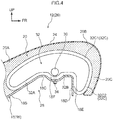
Fig. 4 is a cross-sectional view that corresponds toFig. 3 and shows the vehicle seat of the second embodiment, and shows a state in which an airbag has inflated. - A
vehicle seat 10 relating to a first embodiment of the present disclosure is described by usingFig. 1 andFig. 2 . Note that, in the following explanation, when description is given by using front-rear, left-right and up-down directions, they refer to the front-rear, the left-right, and the up-down directions as seen from a passenger who is seated in thevehicle seat 10. Further, arrow FR that is shown appropriately in the respective drawings indicates a seat forward direction, arrow UP indicates a seat upward direction, arrow RH indicates a seat rightward direction, and arrow LH indicates a seat leftward direction. Further, the left-right direction coincides with a seat transverse direction. - As shown in
Fig. 1 , thevehicle seat 10 of the present embodiment has aseat cushion 12 that supports buttocks P1 and a femoral region P2 of a passenger P (seated passenger), and aseatback 14 that supports a back portion P3 of the passenger P. Thevehicle seat 10 of the present embodiment is provided in a cabin of a self-driving vehicle. The seat front side of thevehicle seat 10 is fixed in a state of facing toward a rear side of the vehicle. Note that there may be a structure in which the seat front side of thevehicle seat 10 is made to face toward a front side of the vehicle due to thevehicle seat 10 being rotated. Further, thevehicle seat 10 of the present embodiment can also be applied to manually-driven vehicles. - The
seat cushion 12 has apanel member 18 that structures a portion of aframe 16 of theseat cushion 12, aseat cushion pad 20 that is mounted to theframe 16 of theseat cushion 12, and anenergy absorbing member 22 that is joined to thepanel member 18. - The
panel member 18 is formed by using a metal plate such as a steel plate or the like. Thispanel member 18 has abottom surface portion 18A that extends in the front-rear direction and the seat transverse direction at a position facing, in the up-down direction, the buttocks P1 of the passenger P seated on theseat cushion 12. Further, thepanel member 18 has aninclined surface portion 18B that extends from a front end of thebottom surface portion 18A so as to incline toward the upper side while heading toward the seat front side. Moreover, thepanel member 18 has apeak surface portion 18C that extends from a front end of theinclined surface portion 18B toward the seat front side and thepeak surface portion 18C is substantially parallel to the front-rear direction and the transverse direction of thevehicle seat 10. Further, thepanel member 18 has afront surface portion 18D that extends toward a lower side from a front end of thepeak surface portion 18C and aface 18E faces toward a front side of thevehicle seat 10. In the present embodiment, thefront surface portion 18D is inclined slightly toward a rear side of thevehicle seat 10 while heading toward the lower side. - The
seat cushion pad 20 is formed by using a soft polyurethane foam or the like. Theseat cushion pad 20 has amain portion 20A, which is disposed along upper surfaces of thebottom surface portion 18A, theinclined surface portion 18B and thepeak surface portion 18C of thepanel member 18. Theseat cushion pad 20 further has an upperside covering portion 20B, which extends toward the seat front side from a front end of themain portion 20A and covers anupper side portion 22A of theenergy absorbing member 22 that is described later. Further, theseat cushion pad 20 has a frontside covering portion 20C that extends toward a lower side from a front end of the upperside covering portion 20B and covers a seatfront side portion 22B of theenergy absorbing member 22. Note that a portion, which can be seen by the passenger P, of the above-describedseat cushion pad 20 is covered by askin material 24. - The
energy absorbing member 22 is formed by using a material that is harder than theseat cushion pad 20, and is formed in the shape of a rectangular block whose length direction is along the seat transverse direction. Theenergy absorbing member 22 is formed by ribs or a honeycomb structural body that is formed from a hard urethane resin or a foamed polypropylene resin. - A
rear side surface 22C of theenergy absorbing member 22 is joined via an adhesive or the like to the seatfront side face 18E of thefront surface portion 18D of thepanel member 18. Due thereto, theenergy absorbing member 22 is fixed to thepanel member 18. Further, in the state in which theenergy absorbing member 22 is fixed to thepanel member 18, theupper side portion 22A projects out toward an upper side with respect to thepeak surface portion 18C of thepanel member 18. - Operation and effects of the present embodiment are described next.
- When the
vehicle 10 collides at a front side thereof in a state in which the above-describedvehicle seat 10 faces toward a rear side of the vehicle, the passenger P who is seated in thevehicle seat 10 inertially moves toward the seat rear side (the vehicle front side). Due thereto, the back portion P3 of the passenger P pushes theseatback 14, and legs P4 (calves P5) of the passenger P push theenergy absorbing member 22 via the frontside covering portion 20C of theseat cushion pad 20. Due thereto, theenergy absorbing member 22 deforms between the legs P4 of the passenger P and thefront surface portion 18D of thepanel member 18. As a result, the injury degree of the calves P5 of the passenger P can be reduced. In the present embodiment, theenergy absorbing member 22 irreversibly deforms, between the legs P4 and thefront surface portion 18D. By providing thisenergy absorbing member 22 that cannot be restored from its deformed state in this way, the kinetic energy of the legs P4 of the passenger P can be absorbed effectively. Due thereto, the injury degree of the calves P5 of the passenger P can be reduced effectively as compared with a structure that merely increases the thickness of the frontside covering portion 20C of theseat cushion pad 20. - Note that the injury degree of the calves P5 of the passenger P can be effectively reduced in the same way also in a case in which the vehicle collides at a rear side thereof in a state in which the
vehicle seat 10 is facing toward a front side of the vehicle. - Further, in the present embodiment, the
energy absorbing member 22 is fixed via an adhesive to thefront surface portion 18D of thepanel member 18. Due thereto, the mounted posture of theenergy absorbing member 22 with respect to thepanel member 18 can be stabilized. - The
energy absorbing member 22 and theseat cushion pad 20 may be made to be integral by insert molding or the like. In this structure, the mounting of theenergy absorbing member 22 can be completed simultaneously with the work of mounting theseat cushion pad 20 to the frame 16 (thepanel member 18 and the like) of the seat cushion. - A
vehicle seat 26 relating to a second embodiment of the present invention is described by usingFig. 3 andFig. 4 . Note that, at thevehicle seat 26 relating to the second embodiment, members and portions corresponding to those of thevehicle seat 10 relating to the above-described first embodiment are denoted by the same reference numerals as the corresponding members and portions of thevehicle seat 10 relating to the first embodiment, and there are cases in which description thereof is omitted. - As shown in
Fig. 3 andFig. 4 , thevehicle seat 26 of the present embodiment has the feature that anairbag device 28 is provided instead of the energy absorbing member 22 (seeFig. 1 ) of thevehicle seat 10 relating to the first embodiment. - The
airbag device 28 is provided between thepanel member 18 and theseat cushion pad 20. Thisairbag device 28 is structured to include an inflator 30 that generates gas by being operated, and anairbag 32 that serves as an energy absorbing member and that inflates due to gas generated by the inflator 30 being supplied to an interior of theairbag 32. - The inflator 30 is disposed at a substantially central portion in the front-rear direction and the seat transverse direction of the
airbag device 28. A fixing member 34 (stud bolt) for fixing theairbag device 28 to thepanel member 18 is provided integrally with theinflator 30. Note that acavity 18F is formed at thepeak surface portion 18C of thepanel member 18 at a region with which the fixingmember 34 is engaged. - The
airbag 32 is formed in a rectangular shape in the state before gas is supplied to the interior thereof (the state in which theairbag 32 is folded-up). Further, in the state in which theairbag device 28 is fixed to thepanel member 18 via theinflator 30, arear side portion 32A in the seat front-rear direction of theairbag 32 is disposed along an upper surface of theinclined surface portion 18B of thepanel member 18. Further, a front-rear directioncentral portion 32B of theairbag 32 is disposed along an upper surface of thepeak surface portion 18C of thepanel member 18. A portion, which corresponds to the inflator 30, at the front-rear directioncentral portion 32B of theairbag device 28 bulges-out toward the upper side. A cavity 20D is formed at themain portion 20A of theseat cushion pad 20 so as to correspond to this bulge at theairbag device 28. Further, a seatfront side portion 32C of theairbag 32 is disposed along the seatfront side face 18E of thefront surface portion 18D of thepanel member 18. - Operation and effects of the present embodiment are described next.
- When the vehicle collides at a front side thereof in a state in which the above-described
vehicle seat 26 faces toward the rear side of the vehicle, theinflator 30 is operated. Then, due to the gas generated by the inflator 30 being supplied to the interior of theairbag 32, theairbag 32 inflates as shown inFig. 4 . - The seat
rear side portion 32A, the front-rear directioncentral portion 32B, and an upper portion 32C1 of the seatfront side portion 32C of theairbag 32 that has inflated push, toward the upper side, the seat front side portion of themain portion 20A and the upperside covering portion 20B of theseat cushion pad 20. As a result, the seat front side portion of theseat cushion pad 20 bulges toward the seat upper side. Further, a lower portion 32C2 of the seatfront side portion 32C of theairbag 32 that has inflated is disposed along the seatfront side face 18E of thefront surface portion 18D of thepanel member 18. - The passenger P who is seated at the
vehicle seat 10 moves inertially toward the seat rear side, and the legs P4 (the calves P5) of the passenger P push thefront side portion 32C of theairbag 32 via the frontside covering portion 20C of theseat cushion pad 20. Due thereto, the lower portion 32C2 of the seatfront side portion 32C of theairbag 32 deforms between the legs P4 and thefront surface portion 18D. As a result, the kinetic energy of the legs P4 of the passenger P is absorbed, and the injury degree of the calves P5 of the passenger P can be reduced. - In the
vehicle seat 26 of the present embodiment, due to theairbag 32 inflating, the seat front side portion of theseat cushion pad 20 bulges toward the seat upper side. Therefore, at the time when the vehicle collides at a rear side thereof in the state in which thevehicle seat 26 is facing toward the rear side of the vehicle, due to the inflator 30 being operated, the buttocks P1 of the passenger P who has moved inertially toward the seat front side can be restrained by the bulged-out front end portion of theseat cushion pad 20. As a result, the occurrence of the submarine phenomenon can be suppressed. - Note that, also in a case in which the vehicle collides at a rear side thereof in a state in which the
vehicle seat 26 is facing toward the front side of the vehicle, similarly, the injury degree of the calves P5 of the passenger P can be effectively reduced. Further, also in a case in which the vehicle collides at a front side thereof in a state in which thevehicle seat 26 of the present embodiment is facing toward the front side of the vehicle, similarly, the buttocks P1 of the passenger P who has moved inertially toward the seat front side can be restrained by the bulged-out front end portion of theseat cushion pad 20. - Note that an example is described in which the
vehicle seat 26 of the present embodiment is structured such that the seat front side portion of theseat cushion pad 20 bulges toward the seat upper side due to theairbag 32 inflating. However, the present disclosure is not limited to this. For example, there may be a structure in which an airbag that is disposed only along thefront surface portion 18D of thepanel member 18 is provided, and the seat front side portion of theseat cushion pad 20 does not bulge toward the seat upper side. - Although embodiments of the present disclosure have been described above, the present disclosure is not limited to the above, and can, of course, be implemented by being modified in various ways other than the above within a scope of the present disclosure.
Claims (5)
- A vehicle seat (10, 26) including a seat cushion (12) and a seat back (14), the vehicle seat (10) comprising:a front surface portion (18D) that structures a portion of a frame (16) of the seat cushion (12), which is adapted to support buttocks of a passenger, the front surface portion (18D) being disposed at a front part of the vehicle seat (10), and a face (18E) of the front surface portion (18D) facing toward a front side of the vehicle seat (10, 26); andan energy absorbing member (22, 32) that is provided along the face (18E) of the front surface portion (18D), and the energy absorbing member (22, 32) is configured to irreversibly deform by being pushed toward a rear side of the vehicle seat (10, 26).
- The vehicle seat (10) of claim 1, wherein:a seat cushion pad (20) is mounted to the frame (16) of the seat cushion (12), andthe energy absorbing member (22) is formed integrally with the seat cushion pad (20).
- The vehicle seat (10) of claim 1, wherein the energy absorbing member (22) is fixed to the face (18E) of the front surface portion (18D).
- The vehicle seat (26) of claim 1, wherein:the energy absorbing member (32) is an airbag (32) that inflates in a case in which the passenger inertially moves toward the rear side of the vehicle seat (26), andat least a portion of the airbag (32) after inflation is disposed along the face (18E) of the front surface portion (18D).
- The vehicle seat (26) of claim 4, wherein:a seat cushion pad (20) is mounted to the frame (16) of the seat cushion (12),the airbag (32) is disposed between the frame (16) and the seat cushion pad (20), anda portion at a seat front side of the seat cushion pad (20) is configured to bulge toward a seat upper side due to the airbag inflating.
Applications Claiming Priority (1)
| Application Number | Priority Date | Filing Date | Title |
|---|---|---|---|
| JP2018161140A JP7143684B2 (en) | 2018-08-30 | 2018-08-30 | vehicle seat |
Publications (2)
| Publication Number | Publication Date |
|---|---|
| EP3616981A1 true EP3616981A1 (en) | 2020-03-04 |
| EP3616981B1 EP3616981B1 (en) | 2021-05-26 |
Family
ID=67659515
Family Applications (1)
| Application Number | Title | Priority Date | Filing Date |
|---|---|---|---|
| EP19192632.8A Active EP3616981B1 (en) | 2018-08-30 | 2019-08-20 | Vehicle seat |
Country Status (4)
| Country | Link |
|---|---|
| US (1) | US20200070768A1 (en) |
| EP (1) | EP3616981B1 (en) |
| JP (1) | JP7143684B2 (en) |
| CN (1) | CN110871720B (en) |
Families Citing this family (9)
| Publication number | Priority date | Publication date | Assignee | Title |
|---|---|---|---|---|
| US11173861B2 (en) * | 2019-12-12 | 2021-11-16 | Ford Global Technologies, Llc | Assembly including foam pad fixed to airbag |
| JP7332107B2 (en) * | 2020-02-28 | 2023-08-23 | 株式会社大一商会 | game machine |
| JP7332103B2 (en) * | 2020-02-28 | 2023-08-23 | 株式会社大一商会 | game machine |
| JP7332106B2 (en) * | 2020-02-28 | 2023-08-23 | 株式会社大一商会 | game machine |
| JP7332104B2 (en) * | 2020-02-28 | 2023-08-23 | 株式会社大一商会 | game machine |
| JP7332105B2 (en) * | 2020-02-28 | 2023-08-23 | 株式会社大一商会 | game machine |
| JP7332102B2 (en) * | 2020-02-28 | 2023-08-23 | 株式会社大一商会 | game machine |
| US11247629B1 (en) * | 2020-08-17 | 2022-02-15 | Ford Global Technologies, Llc | Vehicle airbag |
| JP7381772B2 (en) * | 2020-11-04 | 2023-11-16 | オートリブ ディベロップメント エービー | Seat built-in airbag device |
Citations (7)
| Publication number | Priority date | Publication date | Assignee | Title |
|---|---|---|---|---|
| DE20301516U1 (en) * | 2003-01-31 | 2003-07-10 | TRW Occupant Restraint Systems GmbH & Co. KG, 73553 Alfdorf | vehicle seat |
| JP2008142120A (en) * | 2006-12-06 | 2008-06-26 | Toyota Motor Corp | seat |
| DE102008029339A1 (en) * | 2008-05-27 | 2009-01-22 | Daimler Ag | Motor vehicle i.e. passenger car, seat, has adjustment elements designed as auxiliary airbags, which are brought into protective configuration before or during collision in non-reversible manner |
| US20090134686A1 (en) * | 2007-11-27 | 2009-05-28 | Honda Motor Co., Ltd. | Vehicle seat |
| EP2193956A1 (en) * | 2008-12-04 | 2010-06-09 | Nissan Motor Company Limited | Vehicle seat |
| EP2623367A1 (en) * | 2010-10-01 | 2013-08-07 | Nissan Motor Co., Ltd | Vehicle seat and stiffness setting method for vehicle seat |
| JP2017149331A (en) | 2016-02-25 | 2017-08-31 | ダイハツ工業株式会社 | Vehicle structure |
Family Cites Families (10)
| Publication number | Priority date | Publication date | Assignee | Title |
|---|---|---|---|---|
| DE7728111U1 (en) * | 1977-09-10 | 1977-12-22 | Recaro Gmbh & Co, 7312 Kirchheim | VEHICLE SEAT |
| GB2323336B (en) * | 1997-03-17 | 2000-12-06 | Autoliv Dev | Improvements in or relating to a vehicle safety seat |
| JP3721934B2 (en) * | 2000-04-17 | 2005-11-30 | ジョンソン コントロールズ オートモーティブ システムズ株式会社 | Electric ottoman device |
| JP2007126117A (en) * | 2005-10-03 | 2007-05-24 | Toyoda Gosei Co Ltd | Vehicle seat |
| JP2007320389A (en) * | 2006-05-31 | 2007-12-13 | Toyoda Gosei Co Ltd | Occupant protection device |
| JP5190341B2 (en) * | 2008-12-10 | 2013-04-24 | 日野自動車株式会社 | Vehicle seat cushion structure |
| JP5296747B2 (en) * | 2010-06-29 | 2013-09-25 | 日本発條株式会社 | Vehicle seat |
| JP2013141960A (en) * | 2012-01-12 | 2013-07-22 | Isuzu Motors Ltd | Seat cushion structure for simple vehicle seat |
| CN203713797U (en) * | 2013-10-18 | 2014-07-16 | 北京汽车股份有限公司 | Automobile seat and automobile |
| CN105313816B (en) * | 2014-06-30 | 2018-12-21 | 天津市沃德美嘉科技有限公司 | Driver's active safety protective device |
-
2018
- 2018-08-30 JP JP2018161140A patent/JP7143684B2/en active Active
-
2019
- 2019-08-06 US US16/532,635 patent/US20200070768A1/en not_active Abandoned
- 2019-08-09 CN CN201910733957.XA patent/CN110871720B/en active Active
- 2019-08-20 EP EP19192632.8A patent/EP3616981B1/en active Active
Patent Citations (7)
| Publication number | Priority date | Publication date | Assignee | Title |
|---|---|---|---|---|
| DE20301516U1 (en) * | 2003-01-31 | 2003-07-10 | TRW Occupant Restraint Systems GmbH & Co. KG, 73553 Alfdorf | vehicle seat |
| JP2008142120A (en) * | 2006-12-06 | 2008-06-26 | Toyota Motor Corp | seat |
| US20090134686A1 (en) * | 2007-11-27 | 2009-05-28 | Honda Motor Co., Ltd. | Vehicle seat |
| DE102008029339A1 (en) * | 2008-05-27 | 2009-01-22 | Daimler Ag | Motor vehicle i.e. passenger car, seat, has adjustment elements designed as auxiliary airbags, which are brought into protective configuration before or during collision in non-reversible manner |
| EP2193956A1 (en) * | 2008-12-04 | 2010-06-09 | Nissan Motor Company Limited | Vehicle seat |
| EP2623367A1 (en) * | 2010-10-01 | 2013-08-07 | Nissan Motor Co., Ltd | Vehicle seat and stiffness setting method for vehicle seat |
| JP2017149331A (en) | 2016-02-25 | 2017-08-31 | ダイハツ工業株式会社 | Vehicle structure |
Also Published As
| Publication number | Publication date |
|---|---|
| EP3616981B1 (en) | 2021-05-26 |
| CN110871720A (en) | 2020-03-10 |
| CN110871720B (en) | 2022-08-23 |
| JP7143684B2 (en) | 2022-09-29 |
| US20200070768A1 (en) | 2020-03-05 |
| JP2020032868A (en) | 2020-03-05 |
Similar Documents
| Publication | Publication Date | Title |
|---|---|---|
| EP3616981B1 (en) | Vehicle seat | |
| JP5590250B2 (en) | Vehicle side door structure and occupant protection system | |
| JP2011056979A (en) | Seat structure of vehicle | |
| CN102596635B (en) | vehicle seat | |
| JP5195852B2 (en) | Vehicle seat | |
| JP6775274B2 (en) | Vehicle structure | |
| JP2013124063A (en) | Far side airbag system for side collision of vehicle | |
| JP2020066422A (en) | Side airbag device | |
| CN110053526A (en) | It is vehicle seat used | |
| JP2016203946A (en) | Vehicle seat | |
| JP6992858B2 (en) | Vehicle seat structure | |
| JP7239801B2 (en) | vehicle seat | |
| JP5208930B2 (en) | Knee restraint airbag device | |
| JP5651655B2 (en) | Vehicle side door | |
| JP7801621B2 (en) | Vehicle seats | |
| JP2007276598A (en) | Vehicular seat, vehicle, and airbag module | |
| KR20120093036A (en) | Unification air-bag module | |
| CN110893807B (en) | Vehicle seat | |
| JP5080216B2 (en) | Steering device, steering wheel | |
| JP4433291B2 (en) | Vehicle seat | |
| JP2015123878A (en) | Pillar garnish and vehicle structure | |
| JP2013124026A (en) | Knee bolster for vehicle | |
| JPH0872644A (en) | Impact energy absorption structure for vehicle interior structural members | |
| JP2011105116A (en) | Interior trim part for vehicle | |
| JP2012153238A (en) | Automobile seat |
Legal Events
| Date | Code | Title | Description |
|---|---|---|---|
| PUAI | Public reference made under article 153(3) epc to a published international application that has entered the european phase |
Free format text: ORIGINAL CODE: 0009012 |
|
| STAA | Information on the status of an ep patent application or granted ep patent |
Free format text: STATUS: REQUEST FOR EXAMINATION WAS MADE |
|
| 17P | Request for examination filed |
Effective date: 20190820 |
|
| AK | Designated contracting states |
Kind code of ref document: A1 Designated state(s): AL AT BE BG CH CY CZ DE DK EE ES FI FR GB GR HR HU IE IS IT LI LT LU LV MC MK MT NL NO PL PT RO RS SE SI SK SM TR |
|
| AX | Request for extension of the european patent |
Extension state: BA ME |
|
| GRAP | Despatch of communication of intention to grant a patent |
Free format text: ORIGINAL CODE: EPIDOSNIGR1 |
|
| STAA | Information on the status of an ep patent application or granted ep patent |
Free format text: STATUS: GRANT OF PATENT IS INTENDED |
|
| INTG | Intention to grant announced |
Effective date: 20210114 |
|
| GRAS | Grant fee paid |
Free format text: ORIGINAL CODE: EPIDOSNIGR3 |
|
| GRAA | (expected) grant |
Free format text: ORIGINAL CODE: 0009210 |
|
| STAA | Information on the status of an ep patent application or granted ep patent |
Free format text: STATUS: THE PATENT HAS BEEN GRANTED |
|
| AK | Designated contracting states |
Kind code of ref document: B1 Designated state(s): AL AT BE BG CH CY CZ DE DK EE ES FI FR GB GR HR HU IE IS IT LI LT LU LV MC MK MT NL NO PL PT RO RS SE SI SK SM TR |
|
| REG | Reference to a national code |
Ref country code: GB Ref legal event code: FG4D |
|
| REG | Reference to a national code |
Ref country code: CH Ref legal event code: EP |
|
| REG | Reference to a national code |
Ref country code: DE Ref legal event code: R096 Ref document number: 602019004859 Country of ref document: DE |
|
| REG | Reference to a national code |
Ref country code: AT Ref legal event code: REF Ref document number: 1395900 Country of ref document: AT Kind code of ref document: T Effective date: 20210615 |
|
| REG | Reference to a national code |
Ref country code: IE Ref legal event code: FG4D |
|
| REG | Reference to a national code |
Ref country code: LT Ref legal event code: MG9D |
|
| REG | Reference to a national code |
Ref country code: AT Ref legal event code: MK05 Ref document number: 1395900 Country of ref document: AT Kind code of ref document: T Effective date: 20210526 |
|
| PG25 | Lapsed in a contracting state [announced via postgrant information from national office to epo] |
Ref country code: HR Free format text: LAPSE BECAUSE OF FAILURE TO SUBMIT A TRANSLATION OF THE DESCRIPTION OR TO PAY THE FEE WITHIN THE PRESCRIBED TIME-LIMIT Effective date: 20210526 Ref country code: LT Free format text: LAPSE BECAUSE OF FAILURE TO SUBMIT A TRANSLATION OF THE DESCRIPTION OR TO PAY THE FEE WITHIN THE PRESCRIBED TIME-LIMIT Effective date: 20210526 Ref country code: FI Free format text: LAPSE BECAUSE OF FAILURE TO SUBMIT A TRANSLATION OF THE DESCRIPTION OR TO PAY THE FEE WITHIN THE PRESCRIBED TIME-LIMIT Effective date: 20210526 Ref country code: AT Free format text: LAPSE BECAUSE OF FAILURE TO SUBMIT A TRANSLATION OF THE DESCRIPTION OR TO PAY THE FEE WITHIN THE PRESCRIBED TIME-LIMIT Effective date: 20210526 Ref country code: BG Free format text: LAPSE BECAUSE OF FAILURE TO SUBMIT A TRANSLATION OF THE DESCRIPTION OR TO PAY THE FEE WITHIN THE PRESCRIBED TIME-LIMIT Effective date: 20210826 |
|
| REG | Reference to a national code |
Ref country code: NL Ref legal event code: MP Effective date: 20210526 |
|
| PG25 | Lapsed in a contracting state [announced via postgrant information from national office to epo] |
Ref country code: GR Free format text: LAPSE BECAUSE OF FAILURE TO SUBMIT A TRANSLATION OF THE DESCRIPTION OR TO PAY THE FEE WITHIN THE PRESCRIBED TIME-LIMIT Effective date: 20210827 Ref country code: IS Free format text: LAPSE BECAUSE OF FAILURE TO SUBMIT A TRANSLATION OF THE DESCRIPTION OR TO PAY THE FEE WITHIN THE PRESCRIBED TIME-LIMIT Effective date: 20210926 Ref country code: LV Free format text: LAPSE BECAUSE OF FAILURE TO SUBMIT A TRANSLATION OF THE DESCRIPTION OR TO PAY THE FEE WITHIN THE PRESCRIBED TIME-LIMIT Effective date: 20210526 Ref country code: NO Free format text: LAPSE BECAUSE OF FAILURE TO SUBMIT A TRANSLATION OF THE DESCRIPTION OR TO PAY THE FEE WITHIN THE PRESCRIBED TIME-LIMIT Effective date: 20210826 Ref country code: PL Free format text: LAPSE BECAUSE OF FAILURE TO SUBMIT A TRANSLATION OF THE DESCRIPTION OR TO PAY THE FEE WITHIN THE PRESCRIBED TIME-LIMIT Effective date: 20210526 Ref country code: RS Free format text: LAPSE BECAUSE OF FAILURE TO SUBMIT A TRANSLATION OF THE DESCRIPTION OR TO PAY THE FEE WITHIN THE PRESCRIBED TIME-LIMIT Effective date: 20210526 Ref country code: PT Free format text: LAPSE BECAUSE OF FAILURE TO SUBMIT A TRANSLATION OF THE DESCRIPTION OR TO PAY THE FEE WITHIN THE PRESCRIBED TIME-LIMIT Effective date: 20210927 Ref country code: SE Free format text: LAPSE BECAUSE OF FAILURE TO SUBMIT A TRANSLATION OF THE DESCRIPTION OR TO PAY THE FEE WITHIN THE PRESCRIBED TIME-LIMIT Effective date: 20210526 |
|
| PG25 | Lapsed in a contracting state [announced via postgrant information from national office to epo] |
Ref country code: NL Free format text: LAPSE BECAUSE OF FAILURE TO SUBMIT A TRANSLATION OF THE DESCRIPTION OR TO PAY THE FEE WITHIN THE PRESCRIBED TIME-LIMIT Effective date: 20210526 |
|
| PG25 | Lapsed in a contracting state [announced via postgrant information from national office to epo] |
Ref country code: SM Free format text: LAPSE BECAUSE OF FAILURE TO SUBMIT A TRANSLATION OF THE DESCRIPTION OR TO PAY THE FEE WITHIN THE PRESCRIBED TIME-LIMIT Effective date: 20210526 Ref country code: RO Free format text: LAPSE BECAUSE OF FAILURE TO SUBMIT A TRANSLATION OF THE DESCRIPTION OR TO PAY THE FEE WITHIN THE PRESCRIBED TIME-LIMIT Effective date: 20210526 Ref country code: DK Free format text: LAPSE BECAUSE OF FAILURE TO SUBMIT A TRANSLATION OF THE DESCRIPTION OR TO PAY THE FEE WITHIN THE PRESCRIBED TIME-LIMIT Effective date: 20210526 Ref country code: CZ Free format text: LAPSE BECAUSE OF FAILURE TO SUBMIT A TRANSLATION OF THE DESCRIPTION OR TO PAY THE FEE WITHIN THE PRESCRIBED TIME-LIMIT Effective date: 20210526 Ref country code: SK Free format text: LAPSE BECAUSE OF FAILURE TO SUBMIT A TRANSLATION OF THE DESCRIPTION OR TO PAY THE FEE WITHIN THE PRESCRIBED TIME-LIMIT Effective date: 20210526 Ref country code: EE Free format text: LAPSE BECAUSE OF FAILURE TO SUBMIT A TRANSLATION OF THE DESCRIPTION OR TO PAY THE FEE WITHIN THE PRESCRIBED TIME-LIMIT Effective date: 20210526 Ref country code: ES Free format text: LAPSE BECAUSE OF FAILURE TO SUBMIT A TRANSLATION OF THE DESCRIPTION OR TO PAY THE FEE WITHIN THE PRESCRIBED TIME-LIMIT Effective date: 20210526 |
|
| REG | Reference to a national code |
Ref country code: DE Ref legal event code: R097 Ref document number: 602019004859 Country of ref document: DE |
|
| PLBE | No opposition filed within time limit |
Free format text: ORIGINAL CODE: 0009261 |
|
| STAA | Information on the status of an ep patent application or granted ep patent |
Free format text: STATUS: NO OPPOSITION FILED WITHIN TIME LIMIT |
|
| PG25 | Lapsed in a contracting state [announced via postgrant information from national office to epo] |
Ref country code: MC Free format text: LAPSE BECAUSE OF FAILURE TO SUBMIT A TRANSLATION OF THE DESCRIPTION OR TO PAY THE FEE WITHIN THE PRESCRIBED TIME-LIMIT Effective date: 20210526 |
|
| REG | Reference to a national code |
Ref country code: BE Ref legal event code: MM Effective date: 20210831 |
|
| 26N | No opposition filed |
Effective date: 20220301 |
|
| PG25 | Lapsed in a contracting state [announced via postgrant information from national office to epo] |
Ref country code: IS Free format text: LAPSE BECAUSE OF FAILURE TO SUBMIT A TRANSLATION OF THE DESCRIPTION OR TO PAY THE FEE WITHIN THE PRESCRIBED TIME-LIMIT Effective date: 20210926 Ref country code: LU Free format text: LAPSE BECAUSE OF NON-PAYMENT OF DUE FEES Effective date: 20210820 Ref country code: AL Free format text: LAPSE BECAUSE OF FAILURE TO SUBMIT A TRANSLATION OF THE DESCRIPTION OR TO PAY THE FEE WITHIN THE PRESCRIBED TIME-LIMIT Effective date: 20210526 |
|
| PG25 | Lapsed in a contracting state [announced via postgrant information from national office to epo] |
Ref country code: IT Free format text: LAPSE BECAUSE OF FAILURE TO SUBMIT A TRANSLATION OF THE DESCRIPTION OR TO PAY THE FEE WITHIN THE PRESCRIBED TIME-LIMIT Effective date: 20210526 Ref country code: IE Free format text: LAPSE BECAUSE OF NON-PAYMENT OF DUE FEES Effective date: 20210820 Ref country code: BE Free format text: LAPSE BECAUSE OF NON-PAYMENT OF DUE FEES Effective date: 20210831 |
|
| REG | Reference to a national code |
Ref country code: CH Ref legal event code: PL |
|
| PG25 | Lapsed in a contracting state [announced via postgrant information from national office to epo] |
Ref country code: LI Free format text: LAPSE BECAUSE OF NON-PAYMENT OF DUE FEES Effective date: 20220831 Ref country code: CH Free format text: LAPSE BECAUSE OF NON-PAYMENT OF DUE FEES Effective date: 20220831 |
|
| P01 | Opt-out of the competence of the unified patent court (upc) registered |
Effective date: 20230427 |
|
| REG | Reference to a national code |
Ref country code: DE Ref legal event code: R084 Ref document number: 602019004859 Country of ref document: DE |
|
| PG25 | Lapsed in a contracting state [announced via postgrant information from national office to epo] |
Ref country code: CY Free format text: LAPSE BECAUSE OF FAILURE TO SUBMIT A TRANSLATION OF THE DESCRIPTION OR TO PAY THE FEE WITHIN THE PRESCRIBED TIME-LIMIT Effective date: 20210526 |
|
| PG25 | Lapsed in a contracting state [announced via postgrant information from national office to epo] |
Ref country code: HU Free format text: LAPSE BECAUSE OF FAILURE TO SUBMIT A TRANSLATION OF THE DESCRIPTION OR TO PAY THE FEE WITHIN THE PRESCRIBED TIME-LIMIT; INVALID AB INITIO Effective date: 20190820 |
|
| REG | Reference to a national code |
Ref country code: GB Ref legal event code: 746 Effective date: 20230816 |
|
| PG25 | Lapsed in a contracting state [announced via postgrant information from national office to epo] |
Ref country code: MK Free format text: LAPSE BECAUSE OF FAILURE TO SUBMIT A TRANSLATION OF THE DESCRIPTION OR TO PAY THE FEE WITHIN THE PRESCRIBED TIME-LIMIT Effective date: 20210526 |
|
| PG25 | Lapsed in a contracting state [announced via postgrant information from national office to epo] |
Ref country code: TR Free format text: LAPSE BECAUSE OF FAILURE TO SUBMIT A TRANSLATION OF THE DESCRIPTION OR TO PAY THE FEE WITHIN THE PRESCRIBED TIME-LIMIT Effective date: 20210526 |
|
| PG25 | Lapsed in a contracting state [announced via postgrant information from national office to epo] |
Ref country code: MT Free format text: LAPSE BECAUSE OF FAILURE TO SUBMIT A TRANSLATION OF THE DESCRIPTION OR TO PAY THE FEE WITHIN THE PRESCRIBED TIME-LIMIT Effective date: 20210526 |
|
| PGFP | Annual fee paid to national office [announced via postgrant information from national office to epo] |
Ref country code: GB Payment date: 20250626 Year of fee payment: 7 |
|
| PGFP | Annual fee paid to national office [announced via postgrant information from national office to epo] |
Ref country code: FR Payment date: 20250610 Year of fee payment: 7 |
|
| PGFP | Annual fee paid to national office [announced via postgrant information from national office to epo] |
Ref country code: DE Payment date: 20250624 Year of fee payment: 7 |