EP3616824A1 - Engine-based welder with auto-start feature - Google Patents
Engine-based welder with auto-start feature Download PDFInfo
- Publication number
- EP3616824A1 EP3616824A1 EP19194226.7A EP19194226A EP3616824A1 EP 3616824 A1 EP3616824 A1 EP 3616824A1 EP 19194226 A EP19194226 A EP 19194226A EP 3616824 A1 EP3616824 A1 EP 3616824A1
- Authority
- EP
- European Patent Office
- Prior art keywords
- engine
- controller
- time period
- welding
- welding system
- Prior art date
- Legal status (The legal status is an assumption and is not a legal conclusion. Google has not performed a legal analysis and makes no representation as to the accuracy of the status listed.)
- Withdrawn
Links
- 238000003466 welding Methods 0.000 claims abstract description 141
- 239000002826 coolant Substances 0.000 claims abstract description 16
- 238000000034 method Methods 0.000 claims description 45
- 230000004044 response Effects 0.000 claims description 12
- 230000015654 memory Effects 0.000 description 8
- 238000004891 communication Methods 0.000 description 6
- 238000010586 diagram Methods 0.000 description 4
- 238000012986 modification Methods 0.000 description 3
- 230000004048 modification Effects 0.000 description 3
- 230000009467 reduction Effects 0.000 description 3
- 230000008901 benefit Effects 0.000 description 2
- 230000000694 effects Effects 0.000 description 2
- 238000010891 electric arc Methods 0.000 description 2
- 239000000446 fuel Substances 0.000 description 2
- 230000007246 mechanism Effects 0.000 description 2
- 230000002093 peripheral effect Effects 0.000 description 2
- 230000008569 process Effects 0.000 description 2
- 238000010079 rubber tapping Methods 0.000 description 2
- 230000000007 visual effect Effects 0.000 description 2
- 238000004804 winding Methods 0.000 description 2
- OKTJSMMVPCPJKN-UHFFFAOYSA-N Carbon Chemical compound [C] OKTJSMMVPCPJKN-UHFFFAOYSA-N 0.000 description 1
- CYTYCFOTNPOANT-UHFFFAOYSA-N Perchloroethylene Chemical compound ClC(Cl)=C(Cl)Cl CYTYCFOTNPOANT-UHFFFAOYSA-N 0.000 description 1
- 230000003213 activating effect Effects 0.000 description 1
- 230000004075 alteration Effects 0.000 description 1
- 230000005540 biological transmission Effects 0.000 description 1
- 229910052799 carbon Inorganic materials 0.000 description 1
- 230000008859 change Effects 0.000 description 1
- 238000010276 construction Methods 0.000 description 1
- 230000009977 dual effect Effects 0.000 description 1
- 230000006870 function Effects 0.000 description 1
- 230000003993 interaction Effects 0.000 description 1
- 239000004973 liquid crystal related substance Substances 0.000 description 1
- 238000012423 maintenance Methods 0.000 description 1
- 238000012544 monitoring process Methods 0.000 description 1
- 230000003287 optical effect Effects 0.000 description 1
- 230000002085 persistent effect Effects 0.000 description 1
- 238000003825 pressing Methods 0.000 description 1
- 238000012545 processing Methods 0.000 description 1
- 230000001360 synchronised effect Effects 0.000 description 1
- XLYOFNOQVPJJNP-UHFFFAOYSA-N water Substances O XLYOFNOQVPJJNP-UHFFFAOYSA-N 0.000 description 1
Images




Classifications
-
- B—PERFORMING OPERATIONS; TRANSPORTING
- B23—MACHINE TOOLS; METAL-WORKING NOT OTHERWISE PROVIDED FOR
- B23K—SOLDERING OR UNSOLDERING; WELDING; CLADDING OR PLATING BY SOLDERING OR WELDING; CUTTING BY APPLYING HEAT LOCALLY, e.g. FLAME CUTTING; WORKING BY LASER BEAM
- B23K9/00—Arc welding or cutting
- B23K9/10—Other electric circuits therefor; Protective circuits; Remote controls
- B23K9/1006—Power supply
- B23K9/1043—Power supply characterised by the electric circuit
- B23K9/1056—Power supply characterised by the electric circuit by using digital means
-
- B—PERFORMING OPERATIONS; TRANSPORTING
- B23—MACHINE TOOLS; METAL-WORKING NOT OTHERWISE PROVIDED FOR
- B23K—SOLDERING OR UNSOLDERING; WELDING; CLADDING OR PLATING BY SOLDERING OR WELDING; CUTTING BY APPLYING HEAT LOCALLY, e.g. FLAME CUTTING; WORKING BY LASER BEAM
- B23K9/00—Arc welding or cutting
- B23K9/10—Other electric circuits therefor; Protective circuits; Remote controls
-
- B—PERFORMING OPERATIONS; TRANSPORTING
- B23—MACHINE TOOLS; METAL-WORKING NOT OTHERWISE PROVIDED FOR
- B23K—SOLDERING OR UNSOLDERING; WELDING; CLADDING OR PLATING BY SOLDERING OR WELDING; CUTTING BY APPLYING HEAT LOCALLY, e.g. FLAME CUTTING; WORKING BY LASER BEAM
- B23K9/00—Arc welding or cutting
- B23K9/10—Other electric circuits therefor; Protective circuits; Remote controls
- B23K9/1006—Power supply
- B23K9/1043—Power supply characterised by the electric circuit
-
- B—PERFORMING OPERATIONS; TRANSPORTING
- B23—MACHINE TOOLS; METAL-WORKING NOT OTHERWISE PROVIDED FOR
- B23K—SOLDERING OR UNSOLDERING; WELDING; CLADDING OR PLATING BY SOLDERING OR WELDING; CUTTING BY APPLYING HEAT LOCALLY, e.g. FLAME CUTTING; WORKING BY LASER BEAM
- B23K9/00—Arc welding or cutting
- B23K9/10—Other electric circuits therefor; Protective circuits; Remote controls
- B23K9/1006—Power supply
-
- B—PERFORMING OPERATIONS; TRANSPORTING
- B23—MACHINE TOOLS; METAL-WORKING NOT OTHERWISE PROVIDED FOR
- B23K—SOLDERING OR UNSOLDERING; WELDING; CLADDING OR PLATING BY SOLDERING OR WELDING; CUTTING BY APPLYING HEAT LOCALLY, e.g. FLAME CUTTING; WORKING BY LASER BEAM
- B23K9/00—Arc welding or cutting
- B23K9/10—Other electric circuits therefor; Protective circuits; Remote controls
- B23K9/1006—Power supply
- B23K9/1012—Power supply characterised by parts of the process
-
- F—MECHANICAL ENGINEERING; LIGHTING; HEATING; WEAPONS; BLASTING
- F02—COMBUSTION ENGINES; HOT-GAS OR COMBUSTION-PRODUCT ENGINE PLANTS
- F02D—CONTROLLING COMBUSTION ENGINES
- F02D29/00—Controlling engines, such controlling being peculiar to the devices driven thereby, the devices being other than parts or accessories essential to engine operation, e.g. controlling of engines by signals external thereto
- F02D29/06—Controlling engines, such controlling being peculiar to the devices driven thereby, the devices being other than parts or accessories essential to engine operation, e.g. controlling of engines by signals external thereto peculiar to engines driving electric generators
-
- F—MECHANICAL ENGINEERING; LIGHTING; HEATING; WEAPONS; BLASTING
- F02—COMBUSTION ENGINES; HOT-GAS OR COMBUSTION-PRODUCT ENGINE PLANTS
- F02N—STARTING OF COMBUSTION ENGINES; STARTING AIDS FOR SUCH ENGINES, NOT OTHERWISE PROVIDED FOR
- F02N11/00—Starting of engines by means of electric motors
- F02N11/08—Circuits specially adapted for starting of engines
- F02N11/0803—Circuits specially adapted for starting of engines characterised by means for initiating engine start or stop
-
- F—MECHANICAL ENGINEERING; LIGHTING; HEATING; WEAPONS; BLASTING
- F02—COMBUSTION ENGINES; HOT-GAS OR COMBUSTION-PRODUCT ENGINE PLANTS
- F02N—STARTING OF COMBUSTION ENGINES; STARTING AIDS FOR SUCH ENGINES, NOT OTHERWISE PROVIDED FOR
- F02N11/00—Starting of engines by means of electric motors
- F02N11/08—Circuits specially adapted for starting of engines
- F02N11/0862—Circuits specially adapted for starting of engines characterised by the electrical power supply means, e.g. battery
Definitions
- the invention is related to a welding system according to claim 1 and to a method of providing and auto-start feature according to claim 9.
- This U.S. Patent Application claims priority to and the benefit of U.S. Provisional Patent Application Serial No. 62/724,147, filed on August 29, 2018 , the disclosure of which is incorporated herein by reference in its entirety.
- U.S. Patent No. 9,573,216, issued on February 21, 2017 is incorporated herein by reference in its entirety.
- Embodiments of the present invention relate to systems and methods related to engine-driven welders.
- embodiments of the present invention relate to systems and methods providing an automatic start feature.
- Arc welding machines can be powered by engine generators, allowing the arc welding machines to be operated independent of a source of utility power.
- Such arc welding machines can have welding power outputs and auxiliary power outputs that allow welding devices and other auxiliary electrical devices (loads) to be operated.
- Certain loads may operate intermittently, and it can be wasteful to keep the engine-generator running when a load is off. To conserve fuel, the engine-generator can be turned off when a load is not on or active. However, the engine-generator will then have to be turned back on when a load is subsequently operational.
- a welding system according to claim 1 is described and a method of providing and auto-start feature according to claim 9.
- Preferred embodiments are subject of the subclaims. It would be desirable to provide an arc welding system having an engine-generator in which the engine-generator can be automatically started and stopped based on the presence or absence of a load.
- Embodiments of the present invention include systems and methods related to engine-driven welding equipment.
- an Auto-Start feature is provided that stops the engine after a user defined period of no welding activity. Welding can be started again simply by touching the electrode to the workpiece.
- a chopper circuit (or inverter circuit) of the welder is shut down and a sense circuit compares the external resistance across the output studs to a Tap Start resistance threshold. If the external resistance is below the threshold, the engine is not shut down and a "No-Load Period" countdown is reset. This avoids nuisance shutdowns and restarts when a very light load such as an across the arc wire feeder is connected.
- a welding system in one embodiment, includes an engine and a generator operatively connected to the engine.
- the welding system also includes a welding power source operatively connected to the generator and the engine and having a controller, where the welding power source is configured to be electrically connected to a welding electrode and a workpiece.
- the controller is configured to determine that an electrical load on the welding system has not been detected for a specified no-load time period while the engine is running, determine that a coolant temperature meets a minimum requirement, command shutdown of the engine in response to determining that the electrical load has not been detected for the specified no-load time period and that the coolant temperature meets the minimum requirement, determine that the electrical load has been detected, in response to a single tap (contact) of the welding electrode to the workpiece, during a specified tap start active time period after the engine has been shut down, and command restart of the engine in response to determining that the electrical load has been detected during the specified tap start active time period.
- the electrical load may be a welding electrical load or an auxiliary electrical load.
- the specified no-load time period and/or the specified tap start active time period may be set by an operator of the welding system.
- the controller is configured to determine that the electrical load has not been detected during the specified tap start active time period after the engine has been shut down, and completely shut down the entire welding system.
- the single tap (contact) of the welding electrode to the workpiece provides that the welding electrode makes electrical contact with the workpiece for at least 50 milliseconds.
- the welding system includes a battery configured to supply electrical power to at least the controller. The controller is configured to draw less electrical power from the battery after the tap start active time period has timed out than during the tap start active time period.
- the controller prior to the controller commanding shut down of the engine, the controller is configured to shut down a chopper or an inverter of the welding power source, compare an external resistance across output studs of the welding power source to a resistance threshold, and allow the engine to be commanded to be shut down unless the external resistance is above the resistance threshold. In one embodiment, when the external resistance is above the resistance threshold, the controller is configured to not command that the engine be shut down, and command resetting of a countdown of the first specified time period.
- a method of providing and auto-start feature capability for an engine-based welding system having a controller includes, when an engine of an engine-based welding system is running, a controller of the engine-based welding system determining that a remote shutdown code has been accepted or that there has been no electrical load detected for a first specified time period. The method also includes, when the engine of the engine-based welding system is running, the controller determining that a coolant temperature meets a minimum requirement. The method further includes the controller shutting down the engine in response to determining that the coolant temperature meets the minimum requirement and determining that no electrical load has been detected for the first specified time period.
- the method also includes the controller determining that the electrical load has been detected, in response to a single tap (contact) of a welding electrode to a workpiece, during a second specified time period after the engine has been shut down, and the controller commanding restart of the engine in response to determining that the electrical load has been detected during the second specified time period.
- the electrical load may be a welding electrical load or an auxiliary electrical load.
- the first specified time period and/or the second specified time period may be set by an operator of the welding system.
- the method includes the controller determining that the electrical load has not been detected during the second specified time period after the engine has been shut down, and completely shutting down the entire engine-based welding system.
- the single tap (contact) of the welding electrode to the workpiece provides that the welding electrode makes electrical contact with the workpiece for at least 50 milliseconds.
- the method includes the controller drawing less electrical power from a battery of the engine-based welding system after the second specified time period has timed out than during the second specified time period.
- the method includes, just prior to the controller shutting down the engine, the controller shutting down a chopper or an inverter of the engine-based welding system, the controller comparing an external resistance across output studs of the engine-based welding system to a resistance threshold, and the controller allowing the shutting down of the engine, unless the external resistance is above the resistance threshold.
- the method includes, when the external resistance is above the resistance threshold, the controller not allowing the shutting down of the engine, and the controller resetting a countdown of the first specified time period.
- Embodiments of engine-based welders having an auto-start feature are disclosed.
- the auto-start feature stops the engine after a user defined period of no welding and/or auxiliary activity. Welding can be started again simply by touching the electrode to the workpiece.
- a chopper circuit (or inverter circuit) of the welder is shut down and a sense circuit compares the external resistance across the output studs to a "tap start resistance threshold". If the external resistance is below the threshold, the engine is not shut down and a "no-load time period" countdown is reset.
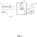
- FIG. 1 illustrates a schematic block diagram of one embodiment of an engine-driven arc welding system (machine) 10.
- the welding system 10 includes a generator 12 driven by an engine 14 thereby forming an engine-generator.
- Example engines include diesel engines, gasoline engines, LP gas engines, and the like.
- the generator 12 generates electrical energy for powering a welding power supply 16 (or "welder").
- the generator 12 can be a synchronous 3-phase alternator. However, the generator need not be a synchronous-3-phase alternator. For example, the generator could be a single phase alternator or a DC generator if desired.
- the generator 12 can have auxiliary windings for providing electrical power to auxiliary loads in addition to the welder 16.
- the welder 16 includes circuitry for generating a welding waveform during arc welding.
- a welding operation is schematically shown in FIG. 1 as an electric arc 18 extending between a welding electrode 20 (consumable or non-consumable) and a workpiece 22.
- the welder 16 also includes circuitry for providing AC or DC power to one or more auxiliary power outputs 24, 26 (e.g., Auxl and Aux2 in FIG. 4 ).
- the auxiliary power outputs 24, 26 are typically powered by the generator 12 and provide electrical power to auxiliary loads 28, 30.
- Example auxiliary loads that can be powered by the welder 16 include tools, lights, pumps, chargers and the like.
- the auxiliary power outputs 24, 26 can include appropriate outlets for facilitating connections to the auxiliary loads 28, 30.
- Example outlets include, for example, NEMA standard outlets commonly found in North America, CEE outlets commonly found in Europe, and other styles of outlets.
- the auxiliary power outputs 24, 26 can include multiple styles of outlets to readily accommodate use in different geographical locations around the world, or the welder 16 can include appropriate adapters to convert one style of outlet to another.
- the output voltage at the auxiliary power outputs 24, 26 is provided by, for example, one or more inverters within the welder 16.
- the welder 16 includes a controller 32 that is operatively connected to the inverter(s) to control the characteristics (e.g., frequency and voltage level) of the output voltage at the auxiliary power outputs 24, 26.
- the controller 32 can provide different voltage levels and frequencies at the auxiliary power outputs 24, 26.
- the auxiliary power outputs 24, 26 can be controlled to provide 60 Hz power at a desired voltage level (e.g., 120V, 240V etc.).
- the auxiliary power outputs 24, 26 can be controlled to provide 50 Hz power at a desired voltage level (e.g., 220V). Other frequencies and voltages are possible as well. For example, when used at an airport, the auxiliary power outputs can be controlled to provide 400 Hz power at 120V.
- the controller 32 can be an electronic controller and may include a processor.
- the controller 32 can include one or more of a microprocessor, a microcontroller, a digital signal processor (DSP), an application specific integrated circuit (ASIC), a field-programmable gate array (FPGA), discrete logic circuitry, or the like.
- the controller 32 can include a memory portion (e.g., RAM or ROM) storing program instructions that cause the controller to provide the functionality ascribed to it herein.
- FIG. 9 herein discusses an example embodiment of a controller in more detail.
- the arc welding system 10 includes an engine starting battery 34 for starting the engine 14.
- the engine 14 can be started automatically by the controller 32 or manually via appropriate user interface components on the engine-generator or welder 16.
- the starting battery 34 is also connected to the welder 16 to provide temporary power to the auxiliary power outputs 24, 26 while the engine 14 is starting and before the output voltage of the generator 12 has reached its proper magnitude and frequency.
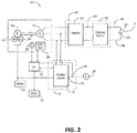
- FIG. 2 illustrates another schematic block diagram of the embodiment of the engine-driven arc welding machine of FIG. 1 , showing additional details.
- Armature windings in the generator 12 supply electrical power to a switching type power converter 40 within the welder.
- Example switching type power converters include DC choppers, inverters, and the like.
- AC power from the generator is rectified by a rectifier 42 within the power converter 40.
- the DC output from the rectifier 42 supplies the welder's DC bus 43.
- the DC bus 43 supplies electrical power to a switching circuit, such as a chopper or inverter 44.
- Electrical leads 46, 48 from the chopper/inverter 44 provide a completed circuit for the arc welding current.
- the arc welding current flows from the chopper/inverter 44 through the electrode 20, across the arc 18, and through the workpiece 22.
- the welding electrode 20 and workpiece 22 are operatively connected to the switching type power converter 40 via the electrical leads 46, 48.
- the welding electrode 20 receives electrical energy from the switching type power converter 40 (as supplied by the engine-generator) for producing the arc 18.
- controller 32 is operatively connected to the switching type power converter 40 to provide control signals to the switching type power converter to control the welding waveform.
- the controller 32 can monitor various aspects of the welding process via feedback signals (e.g., welding current/voltage) and adjust welding parameters during arc welding accordingly.
- the controller 32 is further operatively connected to an auxiliary power supply 50 for supplying electrical energy to the auxiliary load 28 through the auxiliary power output 24.
- the auxiliary power supply 50 can include a rectifier/inverter 52 for converting the AC electrical power received from the generator 12 and the DC electrical power received from the starting battery 34 into a desired output voltage (e.g. AC) and frequency for the auxiliary load 28.
- the auxiliary power supply 50 can include an auxiliary load sensor 54 that detects the presence of an electrical load on the auxiliary power supply 50.
- the auxiliary load sensor 54 outputs a signal to the controller 32 indicating the presence of the electrical load.
- the auxiliary load sensor is shown as a current transformer. However, other types of electrical load sensors could be used, or the auxiliary power supply 50 could directly communicate the existence of an auxiliary load to the controller, such as via digital communications, a contact closure, etc.
- FIG. 3 illustrates one embodiment of an engine-based welding system (machine) 300 that may share many of the same characteristics of the engine-driven welding system (machine) 10 of FIG. 1 and FIG. 2 .
- the engine-based welder 300 of FIG. 3 is built for the construction site, the pipeline, and the rental fleet and includes two complete welders in one. Other embodiments may contain only one welder.
- the engine-based welder 300 of FIG. 3 includes a 26.4 HP water cooled diesel engine which provides enough power for two operators to weld at the same time, or for one operator to gouge with up to a 3/8 inch (9.5 mm) carbon. In the embodiment of FIG. 3 , there is just one machine to service and maintain instead of two.
- Engine RPM varies based on the welding output required, resulting in less fuel being used and less noise being produced.
- An Auto-Start feature stops the engine after a user defined period of no welding/auxiliary load. Welding can be started again simply by touching the electrode to the workpiece a single time.
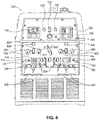
- FIG. 4 illustrates the controls of the engine-based welding machine 300 of FIG. 3 .
- the controls include an LCD screen OperatorA 302, output control OperatorA 304, single/dual operator mode switch 306, wire feeder connection OperatorA 308, wire feeder polarity switch OperatorA 310, remote control connection OperatorA 312, 15 amp circuit breaker 314, 15 amp circuit breaker 316, 25 amp circuit breaker 318, 220V single phase AC Euro Plug 320, positive and negative weld terminal OperatorA 322, 380V three phase AC Euro Plug 324, glow plug push button 326, run/stop switch 328, start push button 330, LCD screen OperatorB 332, emergency stop 334, battery breaker 336, output control OperatorB 338, wire feeder connection OperatorB 340, wire feeder polarity switch OperatorB 342, remote control connection OperatorB 344, residual current device 346, wire feeder circuit breaker 348, 220V single phase AC Euro Plug 350, and positive and negative weld terminal OperatorB 352.
- FIG. 5 illustrates LCD display screens of the engine-based welding machine of FIG. 3 and FIG. 4 .
- the two LCD screens 302 and 332 are color LCD screens that provide increased functionality and easier setup. Intuitive push and turn controls make setup very efficient and guide the user to the correct weld settings. Maintenance reminders assist with maximizing engine life and reliability.
- FIG. 6 illustrates a flow chart of one embodiment of a method 600 providing an Auto-Start feature capability.
- the engine is running.
- a determination is made as to whether a remote shutdown code has been accepted or if there has been no auxiliary electrical load or welding electrical load detected for a time specified by the operator (a first specified time period). If no remote shutdown code has been accepted or if an auxiliary load or a welding load is detected within the time specified by the operator, then the method reverts to block 610 and the engine remains running. However, if a remote shutdown code has been accepted or if there has been no auxiliary load or welding load detected for the time specified by the operator, the method goes to block 630.
- a check is made to determine if a coolant temperature meets a minimum requirement. If the coolant temperature does not meet the minimum requirement, then at block 640 the operator is notified that the coolant temperature is too low and the method reverts to block 610 and the engine remains running. Otherwise, the method goes to block 650 where the engine is shut down. At block 660, if a welding electrical load (or an auxiliary electrical load) is detected during a specified time (second specified time period) after which the engine has been shut down then, at block 670, the engine is automatically restarted. Otherwise the engine remains shut down.
- FIG. 7 illustrates certain details of one embodiment of a PCB control board 700 of the engine-based welding system 300 of FIG. 3 as electrically connected to power output studs 710, a chopper module 720, and a battery 730 of the system 300.
- the PCB control board 700 may be part of a controller similar to, for example, the controller 32 of FIG. 1 and FIG. 2 .
- the chopper module 720 may be similar to the chopper 44 of FIG. 2 .
- the PCB control board 700 is configured to help facilitate the method 600 of FIG.
- PWM pulse width modulator
- VRD voltage reduction device
- ESD electrowetting device
- a voltage feedback circuit 760 providing voltage feedback
- a current sensor 770 providing current feedback
- a power circuit 780 configured to distribute electrical power from the battery 730 to the various other components of the PCB control board 700.
- initial engine startup is done manually at the machine. (Glow plug operation is not included in the Auto-Start circuit.)
- the user begins by going to "SETUP" on an LCD display screen (e.g., 302).
- "Auto-Start On/Off” the user selects "ON” to activate the Auto-Start feature.
- "No-Load Period” the user selects a period between, for example, 10 and 120 minutes. This corresponds to the specified time of block 620 of the method 600.
- “Tap Start Active Time Period” the user selects a period between, for example, 15 and 120 minutes. This corresponds to the specified time of block 660 of the method 600.
- the machine waits during the "Tap Start Active Time Period" for a start signal (e.g., initiated by tapping (contacting) the electrode to the workpiece or by activating the 2-4 switch on the welding gun). Once the start signal is sensed, the engine is started again (at block 670 of the method 600). However, if the "Tap Start Active Time Period" counts down to zero (0) seconds, the machine will be shut down completely and will not be able to be restarted by tapping (contacting) the electrode. The welder has to be restarted manually at the machine (this avoids draining the battery too much).
- a start signal e.g., initiated by tapping (contacting) the electrode to the workpiece or by activating the 2-4 switch on the welding gun.
- a countdown to shutdown is displayed in seconds (during block 610 of the method 600) and is reset each time an electrical load is applied. If the coolant temperature is below, for example, 45 deg. C (at block 630 of the method 600), the countdown will be held at, for example, one (1) second.
- the chopper 720 (or inverter) is shut down and the VRD/electrode sense circuit 750 (see FIG. 7 ) compares the external resistance across the output studs 710 to a Tap Start resistance threshold. If the external resistance is below the threshold, the engine is not shut down and the "No-Load Period" countdown resets. This avoids nuisance shutdowns and restarts when a very light load such as an across the arc wire feeder is connected.
- the feeder's work (power) lead must be disconnected for the "No-Load Period". Reconnecting the lead will restart the machine.
- the engine shuts down (at block 650 of the method 600) and a warning message flashes on the display indicating that the engine may start at any time.
- the engine coolant temperature is above, for example, 45 deg. C
- the engine may be shut down prior to the countdown completing by entering, for example, a remote shutdown code (e.g., 0-10-5-10-0) on a remote control device of the engine-based system 300 (.25 to 3 sec between each entry).
- a remote shutdown code e.g., 0-10-5-10-0
- a countdown is displayed on the left display in seconds showing the remaining "Tap Start Active Time Period".
- the user can single tap (contact) the electrode against the workpiece to make electrical contact and hold contact momentarily (make electrical contact for a minimum of, for example, 50ms. If the user holds the contact, the weld output will not be active until the user releases contact.) Once the user breaks contact, the user may start welding once the engine comes up to speed (e.g., 2 seconds later).
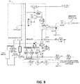
- FIG. 8 illustrates one embodiment of a VRD circuit 755 of the VRD/electrode sense circuit 750 of the PCB control board 700 of FIG. 7 .
- the VRD circuit is turned “ON” by sending a signal (VRDSUPPLY) to the VRD circuit 755 (e.g., from a main chip of the control board 700), resulting in the chopper (or inverter) being shut off.
- a 16VDC circuit is applied to the output studs.
- a 250 ohm resistor is connected to the output studs externally from the control board 700, resulting in a voltage divider to lower the 16VDC supply circuit to 11 VDC open circuit voltage (OCV) on the output studs.
- the 250 ohm resistor is on a chopper panel of the chopper module 720.
- the voltage on the output studs is constantly being monitored through two sense wires that send an analog signal to, for example, the main chip. When the operator taps (contacts) the welding electrode to the workpiece, a voltage drop is created on the voltage divider and the voltage drop is sensed via the monitoring of the output studs. If the 11 VDC OCV drops below 5 VDC, the machine is auto-started. In one embodiment, this occurs when the electrical load draws approximately 120 mA.
- the engine is started by pressing a contact switch (e.g., the 2-4 contact switch) on the welding gun (a control cable may be used to support this). Should the engine fail to start after cranking (e.g., after cranking for 10 seconds), the engine can then be started manually at the machine.
- a contact switch e.g., the 2-4 contact switch
- the engine can then be started manually at the machine.
- the controls are designed to draw minimal power from the battery during the "Tap Start Active Time Period” (disconnect engine ECU, engine alternator flash circuit, etc.).
- the controls use almost no power after the "Tap Start Active Time Period” has timed out.
- the welding system is treated as live. Therefore this window is limited to, for example, 2 hours maximum.
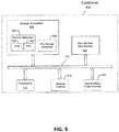
- FIG. 9 illustrates one embodiment of an example controller 900 (e.g., a controller used in the engine-based welding systems described herein).
- the controller 900 may be used as, for example, the controller 32 of FIG. 1 and FIG. 2 .
- the controller 900 includes at least one processor 914 which communicates with a number of peripheral devices via bus subsystem 912. These peripheral devices may include a storage subsystem 924, including, for example, a memory subsystem 928 and a file storage subsystem 926, user interface input devices 922, user interface output devices 920, and a network interface subsystem 916.
- the input and output devices allow user interaction with the controller 900.
- Network interface subsystem 916 provides an interface to outside networks and is coupled to corresponding interface devices in other computer systems.
- the controller 32 of the system 10 may share one or more characteristics with the controller 900 and may be, for example, a conventional computer, a digital signal processor, and/or other computing device.
- User interface input devices 922 may include a keyboard, pointing devices such as a mouse, trackball, touchpad, or graphics tablet, a scanner, a touchscreen incorporated into the display, audio input devices such as voice recognition systems, microphones, and/or other types of input devices.
- pointing devices such as a mouse, trackball, touchpad, or graphics tablet
- audio input devices such as voice recognition systems, microphones, and/or other types of input devices.
- use of the term "input device” is intended to include all possible types of devices and ways to input information into the controller 900 or onto a communication network.
- User interface output devices 920 may include a display subsystem, a printer, a fax machine, or non-visual displays such as audio output devices.
- the display subsystem may include a cathode ray tube (CRT), a flat-panel device such as a liquid crystal display (LCD), a projection device, or some other mechanism for creating a visible image.
- the display subsystem may also provide non-visual display such as via audio output devices.
- output device is intended to include all possible types of devices and ways to output information from the controller 900 to the user or to another machine or computer system.
- Storage subsystem 924 stores programming and data constructs that provide or support some or all of the functionality described herein (e.g., as software modules).
- the storage subsystem 924 may include one or more software modules that support the Auto-Start feature, for example, as described herein.
- Memory 928 used in the storage subsystem can include a number of memories including a main random access memory (RAM) 930 for storage of instructions and data during program execution and a read only memory (ROM) 932 in which fixed instructions are stored.
- a file storage subsystem 926 can provide persistent storage for program and data files, and may include a hard disk drive, a floppy disk drive along with associated removable media, a CD-ROM drive, an optical drive, or removable media cartridges.
- the modules implementing the functionality of certain embodiments may be stored by file storage subsystem 926 in the storage subsystem 924, or in other machines accessible by the processor(s) 914.
- Bus subsystem 912 provides a mechanism for letting the various components and subsystems of the controller 900 communicate with each other as intended. Although bus subsystem 912 is shown schematically as a single bus, alternative embodiments of the bus subsystem may use multiple buses.
- the controller 900 can be of varying types including a workstation, server, computing cluster, blade server, server farm, or any other data processing system or computing device. Due to the ever-changing nature of computing devices and networks, the description of the controller 900 depicted in FIG. 9 is intended only as a specific example for purposes of illustrating some embodiments. Many other configurations of the controller 900 are possible having more or fewer components than the controller depicted in FIG. 9 .
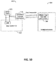
- FIG. 10 illustrates one embodiment of wireless communication between an engine-based welding machine 1000, having a welder display 1005, and a remote control device 1050.
- the remote control device 1050 may be a dedicated remote control device or may be a smart phone having a remote control application and a wireless data transmitter and receiver 1060, in accordance with various embodiments.
- a wireless CAN transmitter and receiver 1010 is fitted to the engine-based welding machine 1000.
- the CAN messages are generated by the main control PCB 1020.
- the welding machine 1000 can be controlled by the wireless remote control device 1050.
- an ignition switch of the welding machine 1000 is turned "ON" for the wireless remote control device 1050 to function.
- the wireless remote control device 1050 may use WiFi, BLUETOOTH®, or other methods of wireless data communication to receive and transmit the CAN messages, in accordance with various embodiments.
- the CAN bus of the welding machine 1000 is broadcast over WiFi, BLUETOOTH®, or other methods of wireless data transmission as well.
- FIG. 11 illustrates displayed examples 1110 and 1120 provided by a smart phone application on a wireless remote control device 1050, in accordance with one embodiment.
- the following can be controlled via the remote control device 1050: turn engine on/off, check auto-shutdown time reading, turn on/off auto start feature, change weld mode and weld output, monitor weld output current and voltage, check engine status (i.e., oil pressure, coolant temperature, RPM, etc.), display active alarms to alert the operator in case there is an issue.
- REFERENCE NUMBERS 10 welding system 316 circuit breaker 12 generator 318 circuit breaker 14 engine 320 Euro plug 16 welding power supply 322 OperatorA 18 electric arc 324 Euro plug 20 welding electrode 326 push button 22 workpiece 328 switch 24 power output 330 push button 26 power output 332 OperatorB 28 auxiliary load 334 emergency stop 30 auxiliary load 336 battery breaker 32 controller 338 OperatorB 34 engine starting battery 340 OperatorB 40 power converter 342 OperatorB 42 rectifier 344 OperatorB 43 DC bus 346 current device 44 inverter 348 circuit breaker 46 electrical lead 350 Euro plug 48 electrical lead 352 OperatorB 50 auxiliary power supply 600 method 52 rectifier/inverter 610 block 54 load sensor 620 block 300 engine-based welding machine 630 block 302 OperatorA 640 block 304 OperatorA 650 block 306 switch 660 block 308 OperatorA 670 block 310 OperatorA 700 board 312 OperatorA 710 output
Landscapes
- Engineering & Computer Science (AREA)
- Mechanical Engineering (AREA)
- Physics & Mathematics (AREA)
- Plasma & Fusion (AREA)
- Chemical & Material Sciences (AREA)
- Combustion & Propulsion (AREA)
- General Engineering & Computer Science (AREA)
- Arc Welding Control (AREA)
- Control Of Vehicle Engines Or Engines For Specific Uses (AREA)
Abstract
In one embodiment, a welding system (10) includes an engine (14) and a generator connected to the engine (14). The welding system (10) also includes a power source having a controller (32). The power source is electrically connected to a welding electrode (20) and a workpiece (22). The controller (32) determines that an electrical load on the welding system (10) has not been detected for a first time period while the engine (14) is running, determines that a coolant temperature meets a minimum requirement, commands shutdown of the engine (14) when the load has not been detected for the first time period and when the coolant temperature meets the minimum requirement, determines that the load has been detected (due to a single contact of the welding electrode (20) to the workpiece (22)) during a second time period after the engine (14) has been shut down, and commands restart of the engine (14) when the load has been detected during the second time period.
Description
- The invention is related to a welding system according to
claim 1 and to a method of providing and auto-start feature according to claim 9. This U.S. Patent Application claims priority to and the benefit ofU.S. Provisional Patent Application Serial No. 62/724,147, filed on August 29, 2018 U.S. Patent No. 9,573,216, issued on February 21, 2017 - Embodiments of the present invention relate to systems and methods related to engine-driven welders. In particular, embodiments of the present invention relate to systems and methods providing an automatic start feature.
- Arc welding machines can be powered by engine generators, allowing the arc welding machines to be operated independent of a source of utility power. Such arc welding machines can have welding power outputs and auxiliary power outputs that allow welding devices and other auxiliary electrical devices (loads) to be operated. Certain loads may operate intermittently, and it can be wasteful to keep the engine-generator running when a load is off. To conserve fuel, the engine-generator can be turned off when a load is not on or active. However, the engine-generator will then have to be turned back on when a load is subsequently operational.
- In order to optimize welding machines with engine generators a welding system according to
claim 1 is described and a method of providing and auto-start feature according to claim 9. Preferred embodiments are subject of the subclaims. It would be desirable to provide an arc welding system having an engine-generator in which the engine-generator can be automatically started and stopped based on the presence or absence of a load. Embodiments of the present invention include systems and methods related to engine-driven welding equipment. In accordance with one embodiment, an Auto-Start feature is provided that stops the engine after a user defined period of no welding activity. Welding can be started again simply by touching the electrode to the workpiece. However, in one embodiment, just prior to auto engine shutdown, a chopper circuit (or inverter circuit) of the welder is shut down and a sense circuit compares the external resistance across the output studs to a Tap Start resistance threshold. If the external resistance is below the threshold, the engine is not shut down and a "No-Load Period" countdown is reset. This avoids nuisance shutdowns and restarts when a very light load such as an across the arc wire feeder is connected. - In one embodiment, a welding system is provided. The welding system includes an engine and a generator operatively connected to the engine. The welding system also includes a welding power source operatively connected to the generator and the engine and having a controller, where the welding power source is configured to be electrically connected to a welding electrode and a workpiece. The controller is configured to determine that an electrical load on the welding system has not been detected for a specified no-load time period while the engine is running, determine that a coolant temperature meets a minimum requirement, command shutdown of the engine in response to determining that the electrical load has not been detected for the specified no-load time period and that the coolant temperature meets the minimum requirement, determine that the electrical load has been detected, in response to a single tap (contact) of the welding electrode to the workpiece, during a specified tap start active time period after the engine has been shut down, and command restart of the engine in response to determining that the electrical load has been detected during the specified tap start active time period. The electrical load may be a welding electrical load or an auxiliary electrical load. The specified no-load time period and/or the specified tap start active time period may be set by an operator of the welding system. In one embodiment, the controller is configured to determine that the electrical load has not been detected during the specified tap start active time period after the engine has been shut down, and completely shut down the entire welding system. In one embodiment, the single tap (contact) of the welding electrode to the workpiece provides that the welding electrode makes electrical contact with the workpiece for at least 50 milliseconds. In one embodiment, the welding system includes a battery configured to supply electrical power to at least the controller. The controller is configured to draw less electrical power from the battery after the tap start active time period has timed out than during the tap start active time period. In one embodiment, prior to the controller commanding shut down of the engine, the controller is configured to shut down a chopper or an inverter of the welding power source, compare an external resistance across output studs of the welding power source to a resistance threshold, and allow the engine to be commanded to be shut down unless the external resistance is above the resistance threshold. In one embodiment, when the external resistance is above the resistance threshold, the controller is configured to not command that the engine be shut down, and command resetting of a countdown of the first specified time period.
- In one embodiment, a method of providing and auto-start feature capability for an engine-based welding system having a controller is provided. The method includes, when an engine of an engine-based welding system is running, a controller of the engine-based welding system determining that a remote shutdown code has been accepted or that there has been no electrical load detected for a first specified time period. The method also includes, when the engine of the engine-based welding system is running, the controller determining that a coolant temperature meets a minimum requirement. The method further includes the controller shutting down the engine in response to determining that the coolant temperature meets the minimum requirement and determining that no electrical load has been detected for the first specified time period. The method also includes the controller determining that the electrical load has been detected, in response to a single tap (contact) of a welding electrode to a workpiece, during a second specified time period after the engine has been shut down, and the controller commanding restart of the engine in response to determining that the electrical load has been detected during the second specified time period. The electrical load may be a welding electrical load or an auxiliary electrical load. The first specified time period and/or the second specified time period may be set by an operator of the welding system. In one embodiment, the method includes the controller determining that the electrical load has not been detected during the second specified time period after the engine has been shut down, and completely shutting down the entire engine-based welding system. In one embodiment, the single tap (contact) of the welding electrode to the workpiece provides that the welding electrode makes electrical contact with the workpiece for at least 50 milliseconds. In one embodiment, the method includes the controller drawing less electrical power from a battery of the engine-based welding system after the second specified time period has timed out than during the second specified time period. In one embodiment, the method includes, just prior to the controller shutting down the engine, the controller shutting down a chopper or an inverter of the engine-based welding system, the controller comparing an external resistance across output studs of the engine-based welding system to a resistance threshold, and the controller allowing the shutting down of the engine, unless the external resistance is above the resistance threshold. In one embodiment, the method includes, when the external resistance is above the resistance threshold, the controller not allowing the shutting down of the engine, and the controller resetting a countdown of the first specified time period.
- Numerous aspects of the general inventive concepts will become readily apparent from the following detailed description of exemplary embodiments and from the accompanying drawings.
- The accompanying drawings, which are incorporated in and constitute a part of the specification, illustrate various embodiments of the disclosure. It will be appreciated that the illustrated element boundaries (e.g., boxes, groups of boxes, or other shapes) in the figures represent one embodiment of boundaries. In some embodiments, one element may be designed as multiple elements or that multiple elements may be designed as one element. In some embodiments, an element shown as an internal component of another element may be implemented as an external component and vice versa. Furthermore, elements may not be drawn to scale.
-
FIG. 1 illustrates a schematic block diagram of one embodiment of an engine-driven arc welding system (machine); -
FIG. 2 illustrates another schematic block diagram of the engine-driven arc welding system (machine) ofFIG. 1 , showing additional details. -
FIG. 3 illustrates one embodiment of an engine-based welding system (machine) that may share many of the same characteristics of the engine-driven welding system (machine) ofFIG. 1 andFIG. 2 ; -
FIG. 4 illustrates the external controls of the engine-based welding system (machine) ofFIG. 3 ; -
FIG. 5 illustrates LCD display screens of the engine-based welding system (machine) ofFIG. 3 andFIG. 4 ; -
FIG. 6 illustrates a flow chart of one embodiment of a method providing an Auto-Start feature capability implemented in the engine-basedwelding system 300 ofFIGS. 3-5 ; -
FIG. 7 illustrates certain details of one embodiment of a PCB control board of the engine-based welding system ofFIG. 3 ; -
FIG. 8 illustrates one embodiment of a voltage reduction (VRD) circuit of a VRD/electrode sense circuit of the PCB control board ofFIG. 7 ; -
FIG. 9 illustrates an example embodiment of a controller (e.g., a controller used in the engine-based welding systems described herein); -
FIG. 10 illustrates one embodiment of wireless communication between an engine-based welding machine and a remote control device; and -
FIG. 11 illustrates examples of a smart phone application and a wireless remote control, in accordance with one embodiment. - The examples and figures herein are illustrative only and are not meant to limit the subject invention.
- Embodiments of engine-based welders having an auto-start feature are disclosed. The auto-start feature stops the engine after a user defined period of no welding and/or auxiliary activity. Welding can be started again simply by touching the electrode to the workpiece. However, in one embodiment, just prior to auto engine shutdown, a chopper circuit (or inverter circuit) of the welder is shut down and a sense circuit compares the external resistance across the output studs to a "tap start resistance threshold". If the external resistance is below the threshold, the engine is not shut down and a "no-load time period" countdown is reset.
-
FIG. 1 illustrates a schematic block diagram of one embodiment of an engine-driven arc welding system (machine) 10. Thewelding system 10 includes agenerator 12 driven by anengine 14 thereby forming an engine-generator. Example engines include diesel engines, gasoline engines, LP gas engines, and the like. Thegenerator 12 generates electrical energy for powering a welding power supply 16 (or "welder"). Thegenerator 12 can be a synchronous 3-phase alternator. However, the generator need not be a synchronous-3-phase alternator. For example, the generator could be a single phase alternator or a DC generator if desired. In certain embodiments, thegenerator 12 can have auxiliary windings for providing electrical power to auxiliary loads in addition to thewelder 16. - The
welder 16 includes circuitry for generating a welding waveform during arc welding. A welding operation is schematically shown inFIG. 1 as anelectric arc 18 extending between a welding electrode 20 (consumable or non-consumable) and aworkpiece 22. Thewelder 16 also includes circuitry for providing AC or DC power to one or more auxiliary power outputs 24, 26 (e.g., Auxl and Aux2 inFIG. 4 ). The auxiliary power outputs 24, 26 are typically powered by thegenerator 12 and provide electrical power toauxiliary loads welder 16 include tools, lights, pumps, chargers and the like. - The auxiliary power outputs 24, 26 can include appropriate outlets for facilitating connections to the
auxiliary loads welder 16 can include appropriate adapters to convert one style of outlet to another. - The output voltage at the auxiliary power outputs 24, 26 is provided by, for example, one or more inverters within the
welder 16. Thewelder 16 includes acontroller 32 that is operatively connected to the inverter(s) to control the characteristics (e.g., frequency and voltage level) of the output voltage at the auxiliary power outputs 24, 26. Through known pulse width modulation techniques, thecontroller 32 can provide different voltage levels and frequencies at the auxiliary power outputs 24, 26. For example, when used in North America, the auxiliary power outputs 24, 26 can be controlled to provide 60 Hz power at a desired voltage level (e.g., 120V, 240V etc.). When used in Europe, the auxiliary power outputs 24, 26 can be controlled to provide 50 Hz power at a desired voltage level (e.g., 220V). Other frequencies and voltages are possible as well. For example, when used at an airport, the auxiliary power outputs can be controlled to provide 400 Hz power at 120V. Thecontroller 32 can be an electronic controller and may include a processor. Thecontroller 32 can include one or more of a microprocessor, a microcontroller, a digital signal processor (DSP), an application specific integrated circuit (ASIC), a field-programmable gate array (FPGA), discrete logic circuitry, or the like. Thecontroller 32 can include a memory portion (e.g., RAM or ROM) storing program instructions that cause the controller to provide the functionality ascribed to it herein. For example,FIG. 9 herein discusses an example embodiment of a controller in more detail. - The
arc welding system 10 includes anengine starting battery 34 for starting theengine 14. Theengine 14 can be started automatically by thecontroller 32 or manually via appropriate user interface components on the engine-generator orwelder 16. In addition to being operatively connected to the engine 14 (e.g., connected to a starting motor attached to the engine), the startingbattery 34 is also connected to thewelder 16 to provide temporary power to the auxiliary power outputs 24, 26 while theengine 14 is starting and before the output voltage of thegenerator 12 has reached its proper magnitude and frequency. -
FIG. 2 illustrates another schematic block diagram of the embodiment of the engine-driven arc welding machine ofFIG. 1 , showing additional details. Armature windings in thegenerator 12 supply electrical power to a switchingtype power converter 40 within the welder. Example switching type power converters include DC choppers, inverters, and the like. AC power from the generator is rectified by a rectifier 42 within thepower converter 40. The DC output from the rectifier 42 supplies the welder'sDC bus 43. TheDC bus 43, in turn, supplies electrical power to a switching circuit, such as a chopper orinverter 44. - Electrical leads 46, 48 from the chopper/
inverter 44 provide a completed circuit for the arc welding current. The arc welding current flows from the chopper/inverter 44 through theelectrode 20, across thearc 18, and through theworkpiece 22. Thewelding electrode 20 andworkpiece 22 are operatively connected to the switchingtype power converter 40 via the electrical leads 46, 48. Thewelding electrode 20 receives electrical energy from the switching type power converter 40 (as supplied by the engine-generator) for producing thearc 18. - In certain embodiments,
controller 32 is operatively connected to the switchingtype power converter 40 to provide control signals to the switching type power converter to control the welding waveform. Thecontroller 32 can monitor various aspects of the welding process via feedback signals (e.g., welding current/voltage) and adjust welding parameters during arc welding accordingly. - The
controller 32 is further operatively connected to anauxiliary power supply 50 for supplying electrical energy to theauxiliary load 28 through theauxiliary power output 24. Theauxiliary power supply 50 can include a rectifier/inverter 52 for converting the AC electrical power received from thegenerator 12 and the DC electrical power received from the startingbattery 34 into a desired output voltage (e.g. AC) and frequency for theauxiliary load 28. Theauxiliary power supply 50 can include anauxiliary load sensor 54 that detects the presence of an electrical load on theauxiliary power supply 50. Theauxiliary load sensor 54 outputs a signal to thecontroller 32 indicating the presence of the electrical load. InFIG. 2 , the auxiliary load sensor is shown as a current transformer. However, other types of electrical load sensors could be used, or theauxiliary power supply 50 could directly communicate the existence of an auxiliary load to the controller, such as via digital communications, a contact closure, etc. -
FIG. 3 illustrates one embodiment of an engine-based welding system (machine) 300 that may share many of the same characteristics of the engine-driven welding system (machine) 10 ofFIG. 1 andFIG. 2 . The engine-basedwelder 300 ofFIG. 3 is built for the construction site, the pipeline, and the rental fleet and includes two complete welders in one. Other embodiments may contain only one welder. In one embodiment, the engine-basedwelder 300 ofFIG. 3 includes a 26.4 HP water cooled diesel engine which provides enough power for two operators to weld at the same time, or for one operator to gouge with up to a 3/8 inch (9.5 mm) carbon. In the embodiment ofFIG. 3 , there is just one machine to service and maintain instead of two. Sound reduction techniques are employed to substantially lower noise levels. Engine RPM varies based on the welding output required, resulting in less fuel being used and less noise being produced. An Auto-Start feature stops the engine after a user defined period of no welding/auxiliary load. Welding can be started again simply by touching the electrode to the workpiece a single time. -
FIG. 4 illustrates the controls of the engine-basedwelding machine 300 ofFIG. 3 . The controls include anLCD screen OperatorA 302,output control OperatorA 304, single/dual operator mode switch 306, wirefeeder connection OperatorA 308, wire feederpolarity switch OperatorA 310, remotecontrol connection OperatorA 312, 15amp circuit breaker 314, 15amp circuit breaker 316, 25amp circuit breaker 318, 220V single phaseAC Euro Plug 320, positive and negativeweld terminal OperatorA 322, 380V three phaseAC Euro Plug 324, glowplug push button 326, run/stop switch 328, startpush button 330,LCD screen OperatorB 332,emergency stop 334,battery breaker 336,output control OperatorB 338, wirefeeder connection OperatorB 340, wire feederpolarity switch OperatorB 342, remotecontrol connection OperatorB 344, residualcurrent device 346, wirefeeder circuit breaker 348, 220V single phaseAC Euro Plug 350, and positive and negativeweld terminal OperatorB 352. -
FIG. 5 illustrates LCD display screens of the engine-based welding machine ofFIG. 3 andFIG. 4 . The twoLCD screens -
FIG. 6 illustrates a flow chart of one embodiment of amethod 600 providing an Auto-Start feature capability. Atblock 610, the engine is running. Atblock 620, a determination is made as to whether a remote shutdown code has been accepted or if there has been no auxiliary electrical load or welding electrical load detected for a time specified by the operator (a first specified time period). If no remote shutdown code has been accepted or if an auxiliary load or a welding load is detected within the time specified by the operator, then the method reverts to block 610 and the engine remains running. However, if a remote shutdown code has been accepted or if there has been no auxiliary load or welding load detected for the time specified by the operator, the method goes to block 630. - At
block 630, a check is made to determine if a coolant temperature meets a minimum requirement. If the coolant temperature does not meet the minimum requirement, then atblock 640 the operator is notified that the coolant temperature is too low and the method reverts to block 610 and the engine remains running. Otherwise, the method goes to block 650 where the engine is shut down. Atblock 660, if a welding electrical load (or an auxiliary electrical load) is detected during a specified time (second specified time period) after which the engine has been shut down then, atblock 670, the engine is automatically restarted. Otherwise the engine remains shut down. -
FIG. 7 illustrates certain details of one embodiment of aPCB control board 700 of the engine-basedwelding system 300 ofFIG. 3 as electrically connected topower output studs 710, achopper module 720, and abattery 730 of thesystem 300. In accordance with one embodiment, thePCB control board 700 may be part of a controller similar to, for example, thecontroller 32 ofFIG. 1 andFIG. 2 . Furthermore, in accordance with one embodiment, thechopper module 720 may be similar to thechopper 44 ofFIG. 2 . ThePCB control board 700 is configured to help facilitate themethod 600 ofFIG. 6 and includes a pulse width modulator (PWM) 740, a voltage reduction device (VRD)/electrode sense circuit 750, avoltage feedback circuit 760 providing voltage feedback, acurrent sensor 770 providing current feedback, and apower circuit 780 configured to distribute electrical power from thebattery 730 to the various other components of thePCB control board 700. - In accordance with one embodiment, initial engine startup is done manually at the machine. (Glow plug operation is not included in the Auto-Start circuit.) To activate the Auto-Start feature, the user begins by going to "SETUP" on an LCD display screen (e.g., 302). Under "Auto-Start On/Off", the user selects "ON" to activate the Auto-Start feature. Under "No-Load Period", the user selects a period between, for example, 10 and 120 minutes. This corresponds to the specified time of
block 620 of themethod 600. Under "Tap Start Active Time Period", the user selects a period between, for example, 15 and 120 minutes. This corresponds to the specified time ofblock 660 of themethod 600. - When the Auto-Start feature shuts off the engine (at
block 650 of the method 600), the machine waits during the "Tap Start Active Time Period" for a start signal (e.g., initiated by tapping (contacting) the electrode to the workpiece or by activating the 2-4 switch on the welding gun). Once the start signal is sensed, the engine is started again (atblock 670 of the method 600). However, if the "Tap Start Active Time Period" counts down to zero (0) seconds, the machine will be shut down completely and will not be able to be restarted by tapping (contacting) the electrode. The welder has to be restarted manually at the machine (this avoids draining the battery too much). Once the engine is running, a countdown to shutdown is displayed in seconds (duringblock 610 of the method 600) and is reset each time an electrical load is applied. If the coolant temperature is below, for example, 45 deg. C (atblock 630 of the method 600), the countdown will be held at, for example, one (1) second. - Just prior to auto engine shutdown (at
block 650 of the method 600), the chopper 720 (or inverter) is shut down and the VRD/electrode sense circuit 750 (seeFIG. 7 ) compares the external resistance across theoutput studs 710 to a Tap Start resistance threshold. If the external resistance is below the threshold, the engine is not shut down and the "No-Load Period" countdown resets. This avoids nuisance shutdowns and restarts when a very light load such as an across the arc wire feeder is connected. To successfully use the Auto-Start feature while wire welding with an across the arc feeder, the feeder's work (power) lead must be disconnected for the "No-Load Period". Reconnecting the lead will restart the machine. - After the countdown completes, the engine shuts down (at
block 650 of the method 600) and a warning message flashes on the display indicating that the engine may start at any time. Optionally, if the engine coolant temperature is above, for example, 45 deg. C, the engine may be shut down prior to the countdown completing by entering, for example, a remote shutdown code (e.g., 0-10-5-10-0) on a remote control device of the engine-basedsystem 300 (.25 to 3 sec between each entry). - Once the engine shuts down, a countdown is displayed on the left display in seconds showing the remaining "Tap Start Active Time Period". The user can single tap (contact) the electrode against the workpiece to make electrical contact and hold contact momentarily (make electrical contact for a minimum of, for example, 50ms. If the user holds the contact, the weld output will not be active until the user releases contact.) Once the user breaks contact, the user may start welding once the engine comes up to speed (e.g., 2 seconds later).
- As an example,
FIG. 8 illustrates one embodiment of aVRD circuit 755 of the VRD/electrode sense circuit 750 of thePCB control board 700 ofFIG. 7 . When the Auto-Start feature shutdowns the engine, the VRD circuit is turned "ON" by sending a signal (VRDSUPPLY) to the VRD circuit 755 (e.g., from a main chip of the control board 700), resulting in the chopper (or inverter) being shut off. Furthermore, a 16VDC circuit is applied to the output studs. A 250 ohm resistor is connected to the output studs externally from thecontrol board 700, resulting in a voltage divider to lower the 16VDC supply circuit to 11 VDC open circuit voltage (OCV) on the output studs. In one embodiment, the 250 ohm resistor is on a chopper panel of thechopper module 720. The voltage on the output studs is constantly being monitored through two sense wires that send an analog signal to, for example, the main chip. When the operator taps (contacts) the welding electrode to the workpiece, a voltage drop is created on the voltage divider and the voltage drop is sensed via the monitoring of the output studs. If the 11 VDC OCV drops below 5 VDC, the machine is auto-started. In one embodiment, this occurs when the electrical load draws approximately 120 mA. - In accordance with one embodiment, for a constant voltage (CV) process, the engine is started by pressing a contact switch (e.g., the 2-4 contact switch) on the welding gun (a control cable may be used to support this). Should the engine fail to start after cranking (e.g., after cranking for 10 seconds), the engine can then be started manually at the machine.
- The controls are designed to draw minimal power from the battery during the "Tap Start Active Time Period" (disconnect engine ECU, engine alternator flash circuit, etc.). The controls use almost no power after the "Tap Start Active Time Period" has timed out. During the "Tap Start Active Time Period", the welding system is treated as live. Therefore this window is limited to, for example, 2 hours maximum.
-
FIG. 9 illustrates one embodiment of an example controller 900 (e.g., a controller used in the engine-based welding systems described herein). Thecontroller 900 may be used as, for example, thecontroller 32 ofFIG. 1 andFIG. 2 . Thecontroller 900 includes at least oneprocessor 914 which communicates with a number of peripheral devices viabus subsystem 912. These peripheral devices may include astorage subsystem 924, including, for example, amemory subsystem 928 and afile storage subsystem 926, userinterface input devices 922, userinterface output devices 920, and anetwork interface subsystem 916. The input and output devices allow user interaction with thecontroller 900.Network interface subsystem 916 provides an interface to outside networks and is coupled to corresponding interface devices in other computer systems. For example, thecontroller 32 of thesystem 10 may share one or more characteristics with thecontroller 900 and may be, for example, a conventional computer, a digital signal processor, and/or other computing device. - User
interface input devices 922 may include a keyboard, pointing devices such as a mouse, trackball, touchpad, or graphics tablet, a scanner, a touchscreen incorporated into the display, audio input devices such as voice recognition systems, microphones, and/or other types of input devices. In general, use of the term "input device" is intended to include all possible types of devices and ways to input information into thecontroller 900 or onto a communication network. - User
interface output devices 920 may include a display subsystem, a printer, a fax machine, or non-visual displays such as audio output devices. The display subsystem may include a cathode ray tube (CRT), a flat-panel device such as a liquid crystal display (LCD), a projection device, or some other mechanism for creating a visible image. The display subsystem may also provide non-visual display such as via audio output devices. In general, use of the term "output device" is intended to include all possible types of devices and ways to output information from thecontroller 900 to the user or to another machine or computer system. -
Storage subsystem 924 stores programming and data constructs that provide or support some or all of the functionality described herein (e.g., as software modules). For example, thestorage subsystem 924 may include one or more software modules that support the Auto-Start feature, for example, as described herein. - Software modules are generally executed by
processor 914 alone or in combination with other processors.Memory 928 used in the storage subsystem can include a number of memories including a main random access memory (RAM) 930 for storage of instructions and data during program execution and a read only memory (ROM) 932 in which fixed instructions are stored. Afile storage subsystem 926 can provide persistent storage for program and data files, and may include a hard disk drive, a floppy disk drive along with associated removable media, a CD-ROM drive, an optical drive, or removable media cartridges. The modules implementing the functionality of certain embodiments may be stored byfile storage subsystem 926 in thestorage subsystem 924, or in other machines accessible by the processor(s) 914. -
Bus subsystem 912 provides a mechanism for letting the various components and subsystems of thecontroller 900 communicate with each other as intended. Althoughbus subsystem 912 is shown schematically as a single bus, alternative embodiments of the bus subsystem may use multiple buses. - The
controller 900 can be of varying types including a workstation, server, computing cluster, blade server, server farm, or any other data processing system or computing device. Due to the ever-changing nature of computing devices and networks, the description of thecontroller 900 depicted inFIG. 9 is intended only as a specific example for purposes of illustrating some embodiments. Many other configurations of thecontroller 900 are possible having more or fewer components than the controller depicted inFIG. 9 . -
FIG. 10 illustrates one embodiment of wireless communication between an engine-basedwelding machine 1000, having awelder display 1005, and aremote control device 1050. Theremote control device 1050 may be a dedicated remote control device or may be a smart phone having a remote control application and a wireless data transmitter andreceiver 1060, in accordance with various embodiments. Referring toFIG. 10 , a wireless CAN transmitter andreceiver 1010 is fitted to the engine-basedwelding machine 1000. The CAN messages are generated by themain control PCB 1020. Once an operator enables a wireless remote mode of thewelding machine 1000, thewelding machine 1000 can be controlled by the wirelessremote control device 1050. In accordance with one embodiment, an ignition switch of thewelding machine 1000 is turned "ON" for the wirelessremote control device 1050 to function. The wirelessremote control device 1050 may use WiFi, BLUETOOTH®, or other methods of wireless data communication to receive and transmit the CAN messages, in accordance with various embodiments. The CAN bus of thewelding machine 1000 is broadcast over WiFi, BLUETOOTH®, or other methods of wireless data transmission as well. -
FIG. 11 illustrates displayed examples 1110 and 1120 provided by a smart phone application on a wirelessremote control device 1050, in accordance with one embodiment. For example, in one embodiment, the following can be controlled via the remote control device 1050: turn engine on/off, check auto-shutdown time reading, turn on/off auto start feature, change weld mode and weld output, monitor weld output current and voltage, check engine status (i.e., oil pressure, coolant temperature, RPM, etc.), display active alarms to alert the operator in case there is an issue. - While the disclosed embodiments have been illustrated and described in considerable detail, it is not the intention to restrict or in any way limit the scope of the appended claims to such detail. It is, of course, not possible to describe every conceivable combination of components or methodologies for purposes of describing the various aspects of the subject matter. Therefore, the disclosure is not limited to the specific details or illustrative examples shown and described. Thus, this disclosure is intended to embrace alterations, modifications, and variations that fall within the scope of the appended claims, which satisfy the statutory subject matter requirements of 35 U.S.C. §101. The above description of specific embodiments has been given by way of example. From the disclosure given, those skilled in the art will not only understand the general inventive concepts and attendant advantages, but will also find apparent various changes and modifications to the structures and methods disclosed. It is sought, therefore, to cover all such changes and modifications as fall within the spirit and scope of the general inventive concepts, as defined by the appended claims, and equivalents thereof.
REFERENCE NUMBERS 10 welding system 316 circuit breaker 12 generator 318 circuit breaker 14 engine 320 Euro plug 16 welding power supply 322 OperatorA 18 electric arc 324 Euro plug 20 welding electrode 326 push button 22 workpiece 328 switch 24 power output 330 push button 26 power output 332 OperatorB 28 auxiliary load 334 emergency stop 30 auxiliary load 336 battery breaker 32 controller 338 OperatorB 34 engine starting battery 340 OperatorB 40 power converter 342 OperatorB 42 rectifier 344 OperatorB 43 DC bus 346 current device 44 inverter 348 circuit breaker 46 electrical lead 350 Euro plug 48 electrical lead 352 OperatorB 50 auxiliary power supply 600 method 52 rectifier/ inverter 610 block 54 load sensor 620 block 300 engine-based welding machine 630 block 302 OperatorA 640 block 304 OperatorA 650 block 306 switch 660 block 308 OperatorA 670 block 310 OperatorA 700 board 312 OperatorA 710 output studs 314 circuit breaker 720 chopper module 730 battery 924 storage subsystem 740 modulator 926 storage subsystem 750 sense circuit 928 memory subsystem 755 circuit 930 access memory 760 feedback circuit 932 memory 770 sensor 1000 welding machine 780 power circuit 1005 welder display 900 controller 1010 receiver 912 bus subsystem 1020 control PCB 914 processor 1050 control device 916 interface subsystem 1110 example 922 input devices 1120 example
Claims (15)
- A welding system (10), the system comprising:an engine (14);a generator (12) operatively connected to the engine (14); anda welding power source operatively connected to the generator (12) and the engine (14) and having a controller (32), wherein the welding power source is configured to be electrically connected to a welding electrode (20) and a workpiece (22), and wherein the controller (32) is configured to:determine that an electrical load on the welding system (10) has not been detected for a specified no-load time period while the engine (14) is running,determine that a coolant temperature meets a minimum requirement,command shutdown of the engine (14) in response to determining that the electrical load has not been detected for the specified no-load time period and that the coolant temperature meets the minimum requirement,determine that the electrical load has been detected, in response to a single contact of the welding electrode (20) to the workpiece (22), during a specified tap start active time period after the engine (14) has been shut down, andcommand restart of the engine (14) in response to determining that the electrical load has been detected during the specified tap start active time period.
- The welding system (10) of claim 1, wherein the electrical load is a welding electrical load and/or
wherein the electrical load is an auxiliary electrical load. - The welding system (10) of claim 1 or 2, wherein the specified no-load time period is set by an operator of the welding system (10), and/or
wherein the specified tap start active time period is set by an operator of the welding system (10). - The welding system (10) of any of the claims 1 to 3, wherein the controller (32) is configured to determine that the electrical load has not been detected during the specified tap start active time period after the engine (14) has been shut down, and completely shut down the entire welding system (10).
- The welding system (10) of any of the claims 1 to 4, wherein the single contact of the welding electrode (20) to the workpiece (22) provides that the welding electrode (20) makes electrical contact with the workpiece (22) for at least 50 milliseconds.
- The welding system (10) of any of the claims 1 to 5, further comprising a battery configured to supply electrical power to at least the controller (32), wherein the controller (32) is configured to draw less electrical power from the battery after the tap start active time period has timed out than during the tap start active time period.
- The welding system (10) of any of the claims 1 to 6, wherein, prior to the controller commanding shut down of the engine (14), the controller (32) is configured to:shut down a chopper or an inverter of the welding power source;compare an external resistance across output studs of the welding power source to a resistance threshold; andallow the engine (14) to be commanded to be shut down unless the external resistance is above the resistance threshold.
- The welding system (10) of claim 7, wherein, when the external resistance is above the resistance threshold, the controller (32) is configured to:not command that the engine (14) be shut down; andcommand resetting of a countdown of the first specified time period.
- A method of providing and auto-start feature capability for an engine-based welding system having a controller, comprising:when an engine of an engine-based welding system is running, a controller of the engine-based welding system determining that a remote shutdown code has been accepted or that there has been no electrical load detected for a first specified time period;when the engine of the engine-based welding system is running, the controller determining that a coolant temperature meets a minimum requirement;the controller shutting down the engine in response to determining that the coolant temperature meets the minimum requirement and determining that no electrical load has been detected for the first specified time period;the controller determining that the electrical load has been detected, in response to a single contact of a welding electrode to a workpiece, during a second specified time period after the engine has been shut down; andthe controller commanding restart of the engine in response to determining that the electrical load has been detected during the second specified time period.
- The method of claim 9, wherein the electrical load is a welding electrical load, and /or
wherein the electrical load is an auxiliary electrical load. - The method of claim 9 or 10, wherein the first specified time period is set by an operator of the engine-based welding system, and/or
wherein the second specified time period is set by an operator of the engine-based welding system. - The method of any of the claims 9 to 11, further comprising the controller determining that the electrical load has not been detected during the second specified time period after the engine has been shut down, and completely shutting down the entire engine-based welding system, and/or
further comprising the controller drawing less electrical power from a battery of the engine-based welding system after the second specified time period has timed out than during the second specified time period. - The method of any of the claims 9 to 12, wherein the single contact of the welding electrode to the workpiece provides that the welding electrode makes electrical contact with the workpiece for at least 50 milliseconds.
- The method of any of the claims 9 to 13, further comprising, just prior to the controller shutting down the engine, the controller:shutting down a chopper or an inverter of the engine-based welding system;comparing an external resistance across output studs of the engine-based welding system to a resistance threshold; andallowing the shutting down of the engine, unless the external resistance is above the resistance threshold.
- The method of claim 14, further comprising, when the external resistance is above the resistance threshold, the controller:not allowing the shutting down of the engine; andresetting a countdown of the first specified time period.
Applications Claiming Priority (2)
| Application Number | Priority Date | Filing Date | Title |
|---|---|---|---|
| US201862724147P | 2018-08-29 | 2018-08-29 | |
| US16/434,290 US11305369B2 (en) | 2018-08-29 | 2019-06-07 | Engine-based welder with auto-start feature |
Publications (1)
| Publication Number | Publication Date |
|---|---|
| EP3616824A1 true EP3616824A1 (en) | 2020-03-04 |
Family
ID=67809250
Family Applications (1)
| Application Number | Title | Priority Date | Filing Date |
|---|---|---|---|
| EP19194226.7A Withdrawn EP3616824A1 (en) | 2018-08-29 | 2019-08-29 | Engine-based welder with auto-start feature |
Country Status (4)
| Country | Link |
|---|---|
| US (1) | US11305369B2 (en) |
| EP (1) | EP3616824A1 (en) |
| JP (1) | JP7369567B2 (en) |
| CN (1) | CN110871310B (en) |
Families Citing this family (2)
| Publication number | Priority date | Publication date | Assignee | Title |
|---|---|---|---|---|
| CN114571035B (en) * | 2022-05-06 | 2022-07-08 | 苏州思萃熔接技术研究所有限公司 | Automatic surfacing device for battery terminal |
| WO2024107883A1 (en) * | 2022-11-15 | 2024-05-23 | Brand Shared Services Llc | Drawn arc welding systems and methods |
Citations (3)
| Publication number | Priority date | Publication date | Assignee | Title |
|---|---|---|---|---|
| US20100193489A1 (en) * | 2009-01-30 | 2010-08-05 | Illinios Tool Works Inc. | Integrated engine-driven generator control system |
| US8338971B2 (en) * | 2009-01-30 | 2012-12-25 | Illinois Tool Works Inc. | Engine-driven generator speed control system and method |
| US9573216B2 (en) | 2014-09-04 | 2017-02-21 | Lincoln Global, Inc. | Engine driven welder with improved fuel economy |
Family Cites Families (21)
| Publication number | Priority date | Publication date | Assignee | Title |
|---|---|---|---|---|
| JPS6264477A (en) * | 1985-09-13 | 1987-03-23 | Yanmar Diesel Engine Co Ltd | Electronic control device for engine welder |
| JPH02151370A (en) * | 1988-12-02 | 1990-06-11 | Yanmar Diesel Engine Co Ltd | Engine welder set |
| US5864116A (en) | 1997-07-25 | 1999-01-26 | The Lincoln Electric Company | D.C. chopper with inductance control for welding |
| US6040556A (en) | 1997-10-01 | 2000-03-21 | Denyo Kabushiki Kaisha | Engine driven arc welder |
| JP2001018063A (en) | 1999-07-01 | 2001-01-23 | Denyo Co Ltd | Engine driven welding generator with AC power supply |
| US7858904B2 (en) * | 2005-01-20 | 2010-12-28 | Illinois Tool Works Inc. | System and method of controlling auxiliary/weld power outputs of a welding-type apparatus |
| US8987638B2 (en) | 2007-06-15 | 2015-03-24 | Denyo Kabushiki Kaisha | Engine driven welding machine |
| JP5142798B2 (en) | 2008-04-17 | 2013-02-13 | デンヨー株式会社 | Engine driven welding machine |
| US8115328B2 (en) * | 2009-01-30 | 2012-02-14 | Illinois Tool Works Inc. | Weld setting based engine-driven generator control system and method |
| US8502115B2 (en) | 2009-06-11 | 2013-08-06 | Illinois Tool Works Inc. | Engine driven welder-generator with chopper circuit |
| US20110152962A1 (en) * | 2009-12-21 | 2011-06-23 | Medtronic, Inc. | Cable Detection System |
| US8680431B2 (en) | 2010-11-15 | 2014-03-25 | Lincoln Global, Inc. | Device and method to control a power source |
| CN103747910B (en) | 2011-05-26 | 2016-03-16 | 维克托设备公司 | Produce the system and method for the welding with the welding control algolithm selected according to setting voltage amplitude |
| CN102896402B (en) | 2011-07-29 | 2014-09-03 | 淮南矿业(集团)有限责任公司 | AC welding machine |
| JP2013090356A (en) | 2011-10-13 | 2013-05-13 | Yamabiko Corp | Engine-driven power generation device |
| CN104416264A (en) | 2013-09-09 | 2015-03-18 | 张丹 | Electric welding machine capable of being automatically started and stopped |
| US9943924B2 (en) | 2014-03-28 | 2018-04-17 | Illinois Tool Works Inc. | Systems and methods for wireless control of an engine-driven welding power supply |
| US20180161910A1 (en) * | 2015-08-06 | 2018-06-14 | Lincoln Global, Inc. | Engine drive welder and methods and systems of controlling the same |
| US20170259368A1 (en) | 2016-03-11 | 2017-09-14 | Lincoln Global, Inc. | Arc welder with variable-frequency auxiliary power output |
| US10071435B2 (en) * | 2016-05-13 | 2018-09-11 | Lincoln Global, Inc. | Welder-generator with start-stop |
| US10751827B2 (en) * | 2016-08-24 | 2020-08-25 | Illinois Tool Works Inc. | Variable speed engine driven generator for providing welding and auxiliary power |
-
2019
- 2019-06-07 US US16/434,290 patent/US11305369B2/en active Active
- 2019-08-20 CN CN201910772455.8A patent/CN110871310B/en active Active
- 2019-08-23 JP JP2019152626A patent/JP7369567B2/en active Active
- 2019-08-29 EP EP19194226.7A patent/EP3616824A1/en not_active Withdrawn
Patent Citations (3)
| Publication number | Priority date | Publication date | Assignee | Title |
|---|---|---|---|---|
| US20100193489A1 (en) * | 2009-01-30 | 2010-08-05 | Illinios Tool Works Inc. | Integrated engine-driven generator control system |
| US8338971B2 (en) * | 2009-01-30 | 2012-12-25 | Illinois Tool Works Inc. | Engine-driven generator speed control system and method |
| US9573216B2 (en) | 2014-09-04 | 2017-02-21 | Lincoln Global, Inc. | Engine driven welder with improved fuel economy |
Also Published As
| Publication number | Publication date |
|---|---|
| CN110871310B (en) | 2023-10-17 |
| JP7369567B2 (en) | 2023-10-26 |
| US20200070271A1 (en) | 2020-03-05 |
| CN110871310A (en) | 2020-03-10 |
| US11305369B2 (en) | 2022-04-19 |
| JP2020032465A (en) | 2020-03-05 |
Similar Documents
| Publication | Publication Date | Title |
|---|---|---|
| US8125094B2 (en) | Engine-driven generator speed control system and method | |
| CN102300665B (en) | The engine-driven generator control system arranged based on welding and method | |
| CA2876231C (en) | Welding system utilizing a distributed power bus | |
| US20090008368A1 (en) | Welder with intelligent battery charger | |
| EP3532236B1 (en) | Portable hybrid welding module with bidirectional dc-dc converter circuit ; hybrid welding system with such portable hybrid welding module | |
| JP5632771B2 (en) | AC current supply device controller and AC current supply method | |
| CA2964691C (en) | Engine generator | |
| US10071435B2 (en) | Welder-generator with start-stop | |
| US11305369B2 (en) | Engine-based welder with auto-start feature | |
| JP5267050B2 (en) | Battery level monitor system | |
| CN109311113A (en) | System and method for controlling auxiliary power supply output voltage using welding output voltage | |
| JP2013090542A (en) | Electronic control device | |
| JPH08205421A (en) | Control device for vehicle alternator | |
| JP2018026349A (en) | Dual battery hybrid engine drive welder and methods and systems of controlling the same | |
| JP2022082221A (en) | In-vehicle charger and in-vehicle charging system | |
| CN109802461B (en) | Multi-mode output power supply circuit for engineering machinery, power supply control system and control method thereof | |
| US11565339B2 (en) | Methods and apparatus for welding arc start assist | |
| JP2013090544A (en) | Electronic control device | |
| JP4330001B2 (en) | Engine generator | |
| JP5814742B2 (en) | Electronic control unit | |
| WO2019046056A1 (en) | Methods and systems for engine idling without a battery | |
| JP3203216U (en) | Automotive rectifier | |
| JP2021064194A (en) | Power control system, video display device, and power control method | |
| JP2020078133A (en) | Solar power generation control device | |
| JP2014207849A (en) | System interconnection inverter and indicator |
Legal Events
| Date | Code | Title | Description |
|---|---|---|---|
| PUAI | Public reference made under article 153(3) epc to a published international application that has entered the european phase |
Free format text: ORIGINAL CODE: 0009012 |
|
| STAA | Information on the status of an ep patent application or granted ep patent |
Free format text: STATUS: THE APPLICATION HAS BEEN PUBLISHED |
|
| AK | Designated contracting states |
Kind code of ref document: A1 Designated state(s): AL AT BE BG CH CY CZ DE DK EE ES FI FR GB GR HR HU IE IS IT LI LT LU LV MC MK MT NL NO PL PT RO RS SE SI SK SM TR |
|
| AX | Request for extension of the european patent |
Extension state: BA ME |
|
| STAA | Information on the status of an ep patent application or granted ep patent |
Free format text: STATUS: THE APPLICATION IS DEEMED TO BE WITHDRAWN |
|
| 18D | Application deemed to be withdrawn |
Effective date: 20200905 |