EP3616814A1 - Cutting insert - Google Patents
Cutting insert Download PDFInfo
- Publication number
- EP3616814A1 EP3616814A1 EP18790658.1A EP18790658A EP3616814A1 EP 3616814 A1 EP3616814 A1 EP 3616814A1 EP 18790658 A EP18790658 A EP 18790658A EP 3616814 A1 EP3616814 A1 EP 3616814A1
- Authority
- EP
- European Patent Office
- Prior art keywords
- cutting edge
- rake face
- continuous
- line segment
- reference surface
- Prior art date
- Legal status (The legal status is an assumption and is not a legal conclusion. Google has not performed a legal analysis and makes no representation as to the accuracy of the status listed.)
- Pending
Links
Images




Classifications
-
- B—PERFORMING OPERATIONS; TRANSPORTING
- B23—MACHINE TOOLS; METAL-WORKING NOT OTHERWISE PROVIDED FOR
- B23C—MILLING
- B23C5/00—Milling-cutters
- B23C5/16—Milling-cutters characterised by physical features other than shape
- B23C5/20—Milling-cutters characterised by physical features other than shape with removable cutter bits or teeth or cutting inserts
- B23C5/22—Securing arrangements for bits or teeth or cutting inserts
- B23C5/2204—Securing arrangements for bits or teeth or cutting inserts with cutting inserts clamped against the walls of the recess in the cutter body by a clamping member acting upon the wall of a hole in the insert
- B23C5/2208—Securing arrangements for bits or teeth or cutting inserts with cutting inserts clamped against the walls of the recess in the cutter body by a clamping member acting upon the wall of a hole in the insert for plate-like cutting inserts
-
- B—PERFORMING OPERATIONS; TRANSPORTING
- B23—MACHINE TOOLS; METAL-WORKING NOT OTHERWISE PROVIDED FOR
- B23C—MILLING
- B23C5/00—Milling-cutters
- B23C5/02—Milling-cutters characterised by the shape of the cutter
- B23C5/06—Face-milling cutters, i.e. having only or primarily a substantially flat cutting surface
-
- B—PERFORMING OPERATIONS; TRANSPORTING
- B23—MACHINE TOOLS; METAL-WORKING NOT OTHERWISE PROVIDED FOR
- B23C—MILLING
- B23C5/00—Milling-cutters
- B23C5/16—Milling-cutters characterised by physical features other than shape
- B23C5/20—Milling-cutters characterised by physical features other than shape with removable cutter bits or teeth or cutting inserts
- B23C5/202—Plate-like cutting inserts with special form
-
- B—PERFORMING OPERATIONS; TRANSPORTING
- B23—MACHINE TOOLS; METAL-WORKING NOT OTHERWISE PROVIDED FOR
- B23C—MILLING
- B23C2200/00—Details of milling cutting inserts
- B23C2200/04—Overall shape
- B23C2200/0416—Irregular
-
- B—PERFORMING OPERATIONS; TRANSPORTING
- B23—MACHINE TOOLS; METAL-WORKING NOT OTHERWISE PROVIDED FOR
- B23C—MILLING
- B23C2200/00—Details of milling cutting inserts
- B23C2200/08—Rake or top surfaces
-
- B—PERFORMING OPERATIONS; TRANSPORTING
- B23—MACHINE TOOLS; METAL-WORKING NOT OTHERWISE PROVIDED FOR
- B23C—MILLING
- B23C2200/00—Details of milling cutting inserts
- B23C2200/12—Side or flank surfaces
- B23C2200/125—Side or flank surfaces discontinuous
- B23C2200/126—Side or flank surfaces discontinuous stepped
-
- B—PERFORMING OPERATIONS; TRANSPORTING
- B23—MACHINE TOOLS; METAL-WORKING NOT OTHERWISE PROVIDED FOR
- B23C—MILLING
- B23C2200/00—Details of milling cutting inserts
- B23C2200/20—Top or side views of the cutting edge
- B23C2200/201—Details of the nose radius and immediately surrounding areas
-
- B—PERFORMING OPERATIONS; TRANSPORTING
- B23—MACHINE TOOLS; METAL-WORKING NOT OTHERWISE PROVIDED FOR
- B23C—MILLING
- B23C2200/00—Details of milling cutting inserts
- B23C2200/20—Top or side views of the cutting edge
- B23C2200/208—Wiper, i.e. an auxiliary cutting edge to improve surface finish
-
- B—PERFORMING OPERATIONS; TRANSPORTING
- B23—MACHINE TOOLS; METAL-WORKING NOT OTHERWISE PROVIDED FOR
- B23C—MILLING
- B23C5/00—Milling-cutters
- B23C5/16—Milling-cutters characterised by physical features other than shape
- B23C5/20—Milling-cutters characterised by physical features other than shape with removable cutter bits or teeth or cutting inserts
Definitions
- the present invention relates to a cutting insert.
- the present application claims a priority based on Japanese Patent Application No. 2017-086479 filed on April 25, 2017 , the entire content of which is incorporated herein by reference.
- Patent Literature 1 discloses a cutting insert for milling.
- the inclination angle of a rake face continuous to a main cutting edge of the cutting insert is substantially unchanged in the extending direction of the main cutting edge.
- the cutting edge has a corner cutting edge, a flat cutting edge, and a main cutting edge, the flat cutting edge being continuous to a first end portion of the corner cutting edge, the main cutting edge being continuous to a second end portion of the corner cutting edge opposite to the first end portion of the corner cutting edge.
- the rake face has a first rising surface portion and a first rake face portion, the first rake face portion being continuous to the first rising surface portion, the first rake face portion being located opposite to the corner cutting edge when viewed from the first rising surface portion.
- a first boundary between the first rising surface portion and the first rake face portion is an inflection point.
- the first boundary includes a first line segment extending, from one of the flat cutting edge and the corner cutting edge, in a direction crossing a straight line extending along the main cutting edge.
- An object of one embodiment of the present invention is to provide a cutting insert by which a scratch mark can be suppressed from remaining in a processed surface of a workpiece.
- Cutting edge 3 of cutting insert 100 has flat cutting edge 13, main cutting edge 23, and corner cutting edge 33.
- cutting insert 100 is attached to a milling cutter body 101.
- milling cutter body 101 By rotation of milling cutter body 101, cutting insert 100 is rotated in a rotation direction A.
- Milling cutter body 101 is moved in a movement direction B while rotating in rotation direction A.
- Cutting edge 3 thus rotating cuts workpiece 70, thereby generating swarf 102.
- swarf 102 is curled whirlingly.
- the curvature radius of a swarf portion cut at the vicinity of the center of corner cutting edge 33 becomes larger than the curvature radius of a swarf portion cut at the vicinity of the end portion of corner cutting edge 33.
- outlet velocity V1 of the swarf portion in the vicinity of the end portion of corner cutting edge 33 becomes lower than outlet velocity V2 of the swarf portion in the vicinity of the center of corner cutting edge 33.
- the outlet direction of swarf 102 becomes a direction D1 including a vector component of an inner circumferential direction of the milling cutter body. Therefore, swarf 102 can be suppressed from coming into contact with processed side surface 72 of workpiece 70. As a result, a scratch mark can be suppressed from remaining in the processed surface of the workpiece.
- cutting insert 100 mainly includes a first surface 5, a second surface 7, and a side surface 6.
- first surface 5 and second surface 7 has a substantially polygonal shape (substantially hexagon shape) with acute angle corners (or right-angle corners) and obtuse angle corners arranged alternately, for example.
- Second surface 7 is located opposite to first surface 5.
- Side surface 6 is continuous to both first surface 5 and second surface 7.
- Cutting insert 100 is provided with a through hole 8 that opens at first surface 5 and second surface 7.
- Side surface 6 surrounds through hole 8.
- fifth inclined surface 31 is inclined at a positive angle relative to reference surface 1.
- the expression “fifth inclined surface 31 is inclined at a positive angle relative to reference surface 1” means that fifth inclined surface 31 is inclined relative to reference surface 1 such that fifth inclined surface 31 becomes lower as fifth inclined surface 31 becomes further away from corner cutting edge 33.
- the expression “fifth inclined surface 31 is inclined at a positive angle relative to reference surface 1” indicates a case where fifth inclined surface 31 extends in the lower right direction when cutting insert 100 is disposed such that corner cutting edge 33 is directed to the left and reference surface 1 is directed upward (see Fig. 4 ).
- first rising surface portion 32 is inclined relative to reference surface 1 to be higher as first rising surface portion 32 becomes further away from corner cutting edge 33. That is, first rising surface portion 32 is inclined at a negative angle relative to reference surface 1.
- First rake face portion 11 may be inclined at a positive angle relative to reference surface 1, may be inclined at a negative angle relative to reference surface 1, or may be parallel to reference surface 1.
- Fig. 5 is a schematic cross sectional view taken along a V-V line of Fig. 3 .
- rake face 9 has fifth inclined surface 31, first rising surface portion 32, and a third rake face portion 15.
- Fifth inclined surface 31 is continuous to corner cutting edge 33.
- Fifth inclined surface 31 is continuous to first rising surface portion 32.
- First rising surface portion 32 is located opposite to corner cutting edge 33 when viewed from fifth inclined surface 31.
- Third rake face portion 15 is continuous to first rising surface portion 32.
- Third rake face portion 15 is located opposite to corner cutting edge 33 when viewed from first rising surface portion 32.
- Sixth inclined surface 2 is continuous to third rake face portion 15.
- Sixth inclined surface 2 is located opposite to corner cutting edge 33 when viewed from third rake face portion 15.
- Reference surface 1 is continuous to sixth inclined surface 2.
- Reference surface 1 is located opposite to corner cutting edge 33 when viewed from sixth inclined surface 2.
- Fig. 7 is a schematic cross sectional view taken along a VII-VII line of Fig. 3 .
- rake face 9 has third region 30, a second rising surface portion 21a, and a second rake face portion 21b.
- Third region 30 is continuous to corner cutting edge 33.
- Third region 30 is continuous to second rising surface portion 21a.
- second rising surface portion 21a is located opposite to corner cutting edge 33.
- Second rake face portion 21b is continuous to second rising surface portion 21a.
- second rake face portion 21b is located opposite to corner cutting edge 33.
- a second boundary J2 between second rising surface portion 21a and second rake face portion 21b may be an inflection point.
- the inclination of the tangent of second rising surface portion 21a is different from the inclination of the tangent of second rake face portion 21b.
- second rising surface portion 21a may form an inwardly protruding curve or may form a straight line.
- second rake face portion 21b may form an outwardly protruding curve or may form a straight line.
- a distance H2 between second boundary J2 and a boundary between third region 30 and second rising surface portion 21a is more than or equal to 0.04 mm and less than or equal to 0.50 mm, for example.
- side surface 6 has a first side portion 61, a second side portion 62, and a third side portion 63.
- a ridgeline between first side portion 61 and first region 10 constitutes flat cutting edge 13.
- a ridgeline between second side portion 62 and second region 20 constitutes main cutting edge 23.
- a ridgeline between third side portion 63 and third region 30 constitutes corner cutting edge 33.
- corner cutting edge 33 has an arc shape.
- each of flat cutting edge 13 and main cutting edge 23 has a straight line shape.
- main cutting edge 23 has a portion that becomes higher as main cutting edge 23 becomes further away from second end portion C2, and has a portion that becomes lower as main cutting edge 23 becomes further away from second end portion C2.
- main cutting edge 23 extends to cross reference surface 1.
- main cutting edge 23 becomes closer to reference surface 1, and after crossing reference surface 1, main cutting edge 23 is separated from reference surface 1.
- first boundary J1 between first rising surface portion 32 and first rake face portion 11 may be continuous to main cutting edge 23.
- First boundary J1 may extend continuously from corner cutting edge 33 to main cutting edge 23.
- Position G1 at which first boundary J1 is continuous to one of flat cutting edge 13 and corner cutting edge 33 may be flat cutting edge 13 may be corner cutting edge 33, or may be first end portion C1.
Landscapes
- Engineering & Computer Science (AREA)
- Mechanical Engineering (AREA)
- Milling Processes (AREA)
Abstract
Description
- The present invention relates to a cutting insert. The present application claims a priority based on Japanese Patent Application No.
2017-086479 filed on April 25, 2017 -
WO2015/174200 (Patent Literature 1) discloses a cutting insert for milling. The inclination angle of a rake face continuous to a main cutting edge of the cutting insert is substantially unchanged in the extending direction of the main cutting edge. - PTL 1:
WO2015/174200 - A cutting insert according to one embodiment of the present invention includes a first surface, a second surface, and a side surface. The second surface is located opposite to the first surface. The side surface is continuous to both of the first surface and the second surface. A ridgeline between the first surface and the side surface includes a cutting edge. The first surface includes a rake face and a reference surface, the rake face being continuous to the cutting edge, the reference surface being located opposite to the cutting edge relative to the rake face, the reference surface having a flat shape. The cutting edge has a corner cutting edge, a flat cutting edge, and a main cutting edge, the flat cutting edge being continuous to a first end portion of the corner cutting edge, the main cutting edge being continuous to a second end portion of the corner cutting edge opposite to the first end portion of the corner cutting edge. The rake face has a first rising surface portion and a first rake face portion, the first rake face portion being continuous to the first rising surface portion, the first rake face portion being located opposite to the corner cutting edge when viewed from the first rising surface portion. In a cross section parallel to the flat cutting edge and perpendicular to the reference surface, a first boundary between the first rising surface portion and the first rake face portion is an inflection point. When viewed in a direction perpendicular to the reference surface, the first boundary includes a first line segment extending, from one of the flat cutting edge and the corner cutting edge, in a direction crossing a straight line extending along the main cutting edge.
-
-
Fig. 1 is a schematic perspective view showing a configuration of a cutting insert according to a first embodiment. -
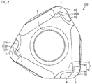
Fig. 2 is a schematic front view showing the configuration of the cutting insert according to the first embodiment. -
Fig. 3 is a schematic front view showing a configuration around a rake face of the cutting insert according to the first embodiment. -
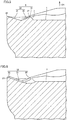
Fig. 4 is a schematic cross sectional view taken along a IV-IV line ofFig. 3 . -
Fig. 5 is a schematic cross sectional view taken along a V-V line ofFig. 3 . -
Fig. 6 is a schematic cross sectional view taken along a VI-VI line ofFig. 3 . -
Fig. 7 is a schematic cross sectional view taken along a VII-VII line ofFig. 3 . -
Fig. 8 is a schematic cross sectional view taken along a VIII-VIII line ofFig. 3 . -
Fig. 9 is a schematic cross sectional view taken along a IX-IX line ofFig. 3 . -
Fig. 10 is a schematic side view showing the configuration of the cutting insert when viewed in a direction of arrow X ofFig. 3 . -
Fig. 11 is a schematic side view showing the configuration of the cutting insert when viewed in a direction of arrow XI ofFig. 3 . -
Fig. 12 is a schematic front view showing a state in which a workpiece is cut using a cutting tool. -
Fig. 13 is a schematic plan view showing a state in which the workpiece is cut using the cutting tool. -
Fig. 14 is a schematic front view showing a configuration of a cutting insert according to a second embodiment. -
Fig. 15 is a schematic front view showing a configuration of a cutting insert according to a third embodiment. -
Fig. 16 shows a relation between an amount of cut (ap) in a depth direction and an amount of cut (ae) in an axial direction when processed using a cutting insert according to asample 1. -
Fig. 17 shows a relation between an amount of cut (ap) in a depth direction and an amount of cut (ae) in an axial direction when processed using a cutting insert according to asample 2. - When a workpiece is processed using the cutting insert disclosed in
WO2015/174200 , a scratch mark may remain in the processed surface of the workpiece. - An object of one embodiment of the present invention is to provide a cutting insert by which a scratch mark can be suppressed from remaining in a processed surface of a workpiece.
- According to one embodiment of the present invention, there can be provided a cutting insert by which a scratch mark can be suppressed from remaining in a processed surface of a workpiece.
- First, the following describes a summary of an embodiment of the present invention.
- (1) A cutting insert 100 according to one embodiment of the present invention includes a
first surface 5, asecond surface 7, and aside surface 6.Second surface 7 is located opposite tofirst surface 5.Side surface 6 is continuous to both offirst surface 5 andsecond surface 7. A ridgeline betweenfirst surface 5 andside surface 6 includes acutting edge 3.First surface 5 includes arake face 9 and areference surface 1,rake face 9 being continuous to cuttingedge 3,reference surface 1 being located opposite to cuttingedge 3 relative torake face 9,reference surface 1 having a flat shape.Cutting edge 3 has acorner cutting edge 33, a flat cutting edge (wiper) 13, and amain cutting edge 23,flat cutting edge 13 being continuous to a first end portion C1 ofcorner cutting edge 33,main cutting edge 23 being continuous to a second end portion C2 ofcorner cutting edge 33 opposite to first end portion C1 ofcorner cutting edge 33.Rake face 9 has a first risingsurface portion 32 and a firstrake face portion 11, firstrake face portion 11 being continuous to first risingsurface portion 32, firstrake face portion 11 being located opposite tocorner cutting edge 33 when viewed from first risingsurface portion 32. In a cross section parallel toflat cutting edge 13 and perpendicular toreference surface 1, a first boundary J1 between first risingsurface portion 32 and firstrake face portion 11 is an inflection point. When viewed in a direction perpendicular toreference surface 1, first boundary J1 includes a first line segment L1 extending, from one offlat cutting edge 13 andcorner cutting edge 33, in a direction crossing a straight line E3 extending alongmain cutting edge 23. - With reference to
Fig. 12 andFig. 13 , the following describes a state in which a corner cutting process is performed to aworkpiece 70 usingcutting insert 100. Cuttingedge 3 ofcutting insert 100 hasflat cutting edge 13,main cutting edge 23, andcorner cutting edge 33. As shown inFig. 13 , cuttinginsert 100 is attached to amilling cutter body 101. By rotation ofmilling cutter body 101, cuttinginsert 100 is rotated in a rotation direction A.Milling cutter body 101 is moved in a movement direction B while rotating in rotation directionA. Cutting edge 3 thus rotatingcuts workpiece 70, thereby generatingswarf 102. Preferably,swarf 102 is curled whirlingly. - In the cutting insert disclosed in
WO2015/174200 , the inclination angle of the rake face continuous to the main cutting edge of the cutting insert is substantially unchanged in the extending direction of the main cutting edge. Accordingly, whenworkpiece 70 is processed using such a cutting insert, the outlet velocity of the swarf portion in the vicinity of the center ofmain cutting edge 23 is similar to or lower than the outlet velocity of the swarf portion in the vicinity ofcorner cutting edge 33. In this case, the outlet direction of the whole ofswarf 102 becomes a direction D2 substantially parallel toside surface 72 ofworkpiece 70 or a direction D3 including a vector component of an outer circumferential direction of the milling cutter body. In these cases, when the diameter of the curl ofswarf 102 becomes large,swarf 102 is brought into contact with processedside surface 72 ofworkpiece 70, with the result that a scratch mark remains inside surface 72.Side surface 72 loses metallic luster and looks white, for example. Moreover,swarf 102 may pass overside surface 72 and come into contact with unprocessedupper surface 73 ofworkpiece 70, with the result that a scratch mark may remain inupper surface 73. In this case,upper surface 73 loses metallic luster and looks white, for example. - Further, when
swarf 102 is brought into contact withside surface 72 to change the outlet direction ofswarf 102,swarf 102 may be brought into contact withbottom surface 71 ofworkpiece 70, which is a surface processed by the flat cutting edge. In this case, a scratch mark is also formed inbottom surface 71 ofworkpiece 70. Further,swarf 102 may be brought into contact with the side surface of cuttinginsert 100, with the result that a scratch mark may be formed in the side surface. - According to cutting
insert 100 according to one embodiment of the present invention, first boundary J1 between first risingsurface portion 32 and firstrake face portion 11 extends, from one offlat cutting edge 13 andcorner cutting edge 33, in the direction crossing the straight line extending alongmain cutting edge 23. First risingsurface portion 32 functions to reduce the outlet velocity ofswarf 102 aroundcorner cutting edge 33. A distance W2 between the vicinity of the center ofcorner cutting edge 33 and the first rake face portion is longer than a distance W1 between the vicinity of the end portion ofcorner cutting edge 33 and the first rake face portion. Therefore, the curvature radius of a swarf portion cut at the vicinity of the center ofcorner cutting edge 33 becomes larger than the curvature radius of a swarf portion cut at the vicinity of the end portion ofcorner cutting edge 33. Hence, outlet velocity V1 of the swarf portion in the vicinity of the end portion ofcorner cutting edge 33 becomes lower than outlet velocity V2 of the swarf portion in the vicinity of the center ofcorner cutting edge 33. As a result, the outlet direction ofswarf 102 becomes a direction D1 including a vector component of an inner circumferential direction of the milling cutter body. Therefore,swarf 102 can be suppressed from coming into contact with processedside surface 72 ofworkpiece 70. As a result, a scratch mark can be suppressed from remaining in the processed surface of the workpiece. - (2) In cutting
insert 100 according to (1), when viewed in the direction perpendicular toreference surface 1, first boundary J1 may include a second line segment L2 continuous to first line segment L1 and extending in a direction inclined relative to first line segment L1. Accordingly, a scratch mark can be further suppressed from remaining in the processed surface of the workpiece. - (3) In cutting
insert 100 according to (2), when viewed in the direction perpendicular toreference surface 1, in a direction parallel toflat cutting edge 13, an interval F1 betweenmain cutting edge 23 and a position G1 at which first line segment L1 is continuous to one offlat cutting edge 13 andcorner cutting edge 33 may be larger than an interval F2 betweenmain cutting edge 23 and a position G2 at which first line segment L1 is continuous to second line segment L2. - (4) In cutting
insert 100 according to (2) or (3), when viewed in the direction perpendicular toreference surface 1, an angle θ2 between second line segment L2 and a straight line E2 parallel toflat cutting edge 13 may be more than or equal to 80° and less than or equal to 90°. - (5) In cutting
insert 100 according to any one of (2) to (4), rakeface 9 may have a second risingsurface portion 21a and a second rake face portion 21b, second rake face portion 21b being continuous to second risingsurface portion 21a, second rake face portion 21b being located opposite tocorner cutting edge 33 when viewed from second risingsurface portion 21a. In a cross section parallel tomain cutting edge 23 and perpendicular toreference surface 1, a second boundary J2 between second risingsurface portion 21a and second rake face portion 21b may be an inflection point. When viewed in the direction perpendicular toreference surface 1, second boundary J2 may include a third line segment L3 continuous to second line segment L2 and extending in a direction inclined relative to second line segment L2. - (6) In cutting
insert 100 according to (5), third line segment L3 may be continuous tomain cutting edge 23. - (7) In cutting
insert 100 according to any one of (1) to (6), when viewed in the direction perpendicular toreference surface 1, an angle θ1 between first line segment L1 and a straight line E1 extending alongflat cutting edge 13 may be more than or equal to 20° and less than or equal to 80°. - (8) In cutting
insert 100 according to (1) or (7), first boundary J1 may be continuous tomain cutting edge 23. - (9) In cutting
insert 100 according to (1) or (7), first boundary J1 may be continuous tocorner cutting edge 33. - Next, the following describes details of the embodiment of the present invention with reference to figures. It should be noted that in the below-mentioned figures, the same or corresponding portions are given the same reference characters and are not described repeatedly.
- First, the following describes a configuration of a
cutting insert 100 according to a first embodiment. - As shown in
Fig. 1 andFig. 2 , cuttinginsert 100 according to the first embodiment mainly includes afirst surface 5, asecond surface 7, and aside surface 6. Each offirst surface 5 andsecond surface 7 has a substantially polygonal shape (substantially hexagon shape) with acute angle corners (or right-angle corners) and obtuse angle corners arranged alternately, for example.Second surface 7 is located opposite tofirst surface 5.Side surface 6 is continuous to bothfirst surface 5 andsecond surface 7. Cuttinginsert 100 is provided with a throughhole 8 that opens atfirst surface 5 andsecond surface 7.Side surface 6 surrounds throughhole 8. - A ridgeline between
first surface 5 andside surface 6 includes cutting edges 3. Cuttingedges 3 are provided at three corners offirst surface 5 having the substantially hexagonal shape, for example. Likewise, a ridgeline betweensecond surface 7 andside surface 6 includes cutting edges 3. Cuttingedges 3 are provided at three corners ofsecond surface 7 having the substantially hexagonal shape, for example.First surface 5 mainly has arake face 9 and areference surface 1.Rake face 9 is continuous to eachcutting edge 3.Reference surface 1 is located opposite to cuttingedge 3 relative to rakeface 9.Reference surface 1 has a flat shape.Reference surface 1 is a seating surface, for example.Reference surface 1 is located between throughhole 8 and rakeface 9. Cuttinginsert 100 is positioned in contact with amilling cutter body 101 at the seating surface, for example. - As shown in
Fig. 3 , cuttingedge 3 mainly has acorner cutting edge 33, a flat cutting edge (wiper) 13, and amain cutting edge 23.Corner cutting edge 33 is located at a rounded nose portion offirst surface 5.Corner cutting edge 33 has a first end portion C1 and a second end portion C2. Second end portion C2 is an end portion opposite to first end portion C1.Flat cutting edge 13 is continuous to first end portion C1 ofcorner cutting edge 33.Main cutting edge 23 is continuous to second end portion C2 ofcorner cutting edge 33. -
Rake face 9 has afirst region 10, asecond region 20, and athird region 30.First region 10 is continuous toflat cutting edge 13.Second region 20 is continuous tomain cutting edge 23.Third region 30 is continuous to corner cuttingedge 33.Third region 30 is located betweenfirst region 10 andsecond region 20.First region 10 may have a firstinclined surface 11 and a secondinclined surface 12. Secondinclined surface 12 is continuous toflat cutting edge 13. Firstinclined surface 11 is continuous to secondinclined surface 12. Firstinclined surface 11 is located opposite toflat cutting edge 13 relative to secondinclined surface 12.Second region 20 may have a thirdinclined surface 21 and a fourthinclined surface 22. Fourthinclined surface 22 is continuous tomain cutting edge 23. Thirdinclined surface 21 is continuous to fourthinclined surface 22. Thirdinclined surface 21 is located opposite tomain cutting edge 23 relative to fourthinclined surface 22.Third region 30 is continuous to corner cuttingedge 33. -
Fig. 4 is a schematic cross sectional view taken along a IV-IV line ofFig. 3 . As shown inFig. 4 , rakeface 9 has a fifthinclined surface 31, a first risingsurface portion 32, and a firstrake face portion 11. Fifthinclined surface 31 is continuous to corner cuttingedge 33. Fifthinclined surface 31 is continuous to first risingsurface portion 32. First risingsurface portion 32 is located opposite tocorner cutting edge 33 when viewed from fifthinclined surface 31. Firstrake face portion 11 is continuous to first risingsurface portion 32. Firstrake face portion 11 is located opposite tocorner cutting edge 33 when viewed from first risingsurface portion 32. - As shown in
Fig. 4 , in a cross section parallel toflat cutting edge 13 and perpendicular toreference surface 1, a first boundary J1 between first risingsurface portion 32 and firstrake face portion 11 is an inflection point. When viewed in the cross section, the inclination of the tangent of first risingsurface portion 32 is different from the inclination of the tangent of firstrake face portion 11. When viewed in the cross section, first risingsurface portion 32 may form an inwardly protruding curve or may form a straight line. When viewed in the cross section, firstrake face portion 11 may form an outwardly protruding curve or may form a straight line. When viewed in a cross section, the inclination angle of first risingsurface portion 32 may become smaller as first risingsurface portion 32 becomes further away fromflat cutting edge 13. In a direction D4 perpendicular toreference surface 1, the height of first boundary J1 may be higher thancorner cutting edge 33. In direction D4 perpendicular toreference surface 1, a distance H1 between first boundary J1 and a boundary between fifthinclined surface 31 and first risingsurface portion 32 is more than or equal to 0.04 mm and less than or equal to 0.50 mm, for example. - As shown in
Fig. 4 , fifthinclined surface 31 is inclined at a positive angle relative to referencesurface 1. The expression "fifthinclined surface 31 is inclined at a positive angle relative to referencesurface 1" means that fifthinclined surface 31 is inclined relative to referencesurface 1 such that fifthinclined surface 31 becomes lower as fifthinclined surface 31 becomes further away fromcorner cutting edge 33. From another viewpoint, the expression "fifthinclined surface 31 is inclined at a positive angle relative to referencesurface 1" indicates a case where fifthinclined surface 31 extends in the lower right direction when cuttinginsert 100 is disposed such thatcorner cutting edge 33 is directed to the left andreference surface 1 is directed upward (seeFig. 4 ). On the other hand, first risingsurface portion 32 is inclined relative to referencesurface 1 to be higher as first risingsurface portion 32 becomes further away fromcorner cutting edge 33. That is, first risingsurface portion 32 is inclined at a negative angle relative to referencesurface 1. Firstrake face portion 11 may be inclined at a positive angle relative to referencesurface 1, may be inclined at a negative angle relative to referencesurface 1, or may be parallel toreference surface 1. - As shown in
Fig. 3 , when viewed in the direction perpendicular toreference surface 1, first boundary J1 between first risingsurface portion 32 and firstrake face portion 11 includes a first line segment L1 extending, from one offlat cutting edge 13 andcorner cutting edge 33, in a direction crossing a straight line E3 extending alongmain cutting edge 23. One offlat cutting edge 13 andcorner cutting edge 33 may beflat cutting edge 13 andcorner cutting edge 33. First line segment L1 may extend from one offlat cutting edge 13 andcorner cutting edge 33 in a direction crossingmain cutting edge 23 or in a direction crossingcorner cutting edge 33. - As shown in
Fig. 3 , when viewed in the direction perpendicular toreference surface 1, an angle θ1 between first line segment L1 and a straight line E1 extending alongflat cutting edge 13 may be more than or equal to 20° and less than or equal to 80°. The upper limit of angle θ1 may be 70° or may be 60°. The lower limit of angle θ1 may be 30° or may be 45°. -
Fig. 5 is a schematic cross sectional view taken along a V-V line ofFig. 3 . As shown inFig. 5 , rakeface 9 has fifth inclinedsurface 31, first risingsurface portion 32, and a thirdrake face portion 15. Fifthinclined surface 31 is continuous to corner cuttingedge 33. Fifthinclined surface 31 is continuous to first risingsurface portion 32. First risingsurface portion 32 is located opposite tocorner cutting edge 33 when viewed from fifthinclined surface 31. Thirdrake face portion 15 is continuous to first risingsurface portion 32. Thirdrake face portion 15 is located opposite tocorner cutting edge 33 when viewed from first risingsurface portion 32. Sixthinclined surface 2 is continuous to thirdrake face portion 15. Sixthinclined surface 2 is located opposite tocorner cutting edge 33 when viewed from thirdrake face portion 15.Reference surface 1 is continuous to sixthinclined surface 2.Reference surface 1 is located opposite tocorner cutting edge 33 when viewed from sixthinclined surface 2. - As shown in
Fig. 5 , in the cross section parallel toflat cutting edge 13 and perpendicular toreference surface 1, first boundary J1 between first risingsurface portion 32 and thirdrake face portion 15 is an inflection point. Fifthinclined surface 31 is inclined at a positive angle relative to referencesurface 1. First risingsurface portion 32 is inclined at a negative angle relative to referencesurface 1. Thirdrake face portion 15 may be inclined at a positive angle relative to referencesurface 1, may be inclined at a negative angle relative to referencesurface 1, or may be parallel toreference surface 1. Sixthinclined surface 2 is inclined at a positive angle. As shown inFig. 5 , in direction D4 perpendicular to referencesurface 1, the height of first boundary J1 may be lower thancorner cutting edge 33. The height of first boundary J1 may be higher thanreference surface 1. - As shown in
Fig. 3 , when viewed in the direction perpendicular toreference surface 1, first boundary J1 may include a second line segment L2. Second line segment L2 is continuous to first line segment L1 and extends in a direction inclined relative to first line segment L1. As shown inFig. 3 , when viewed in the direction perpendicular toreference surface 1, an angle θ2 between second line segment L2 and straight line E2 parallel toflat cutting edge 13 is more than or equal to 80° and not less than or equal to 90°, for example. The lower limit of angle θ2 may be 85° or may be 90°. - As shown in
Fig. 3 , when viewed in the direction perpendicular toreference surface 1, in the direction parallel toflat cutting edge 13, an interval F1 betweenmain cutting edge 23 and a position G1 at which first line segment L1 is continuous to one offlat cutting edge 13 andcorner cutting edge 33 may be larger than an interval F2 betweenmain cutting edge 23 and a position G2 at which first line segment L1 is continuous to second line segment L2. Interval F1 is 1.6 mm, for example. Interval F2 is 0.8 mm, for example. Interval F1 is more than or equal to 0.5 mm and less than or equal to 3.5 mm, for example. Interval F2 is more than or equal to 0.4 mm and less than or equal to 3.0 mm, for example. When viewed in the direction perpendicular toreference surface 1, the curvature radius ofcorner cutting edge 33 is more than or equal to 0.4 mm and less than or equal to 3.5 mm, for example. -
Fig. 6 is a schematic cross sectional view taken along a VI-VI line ofFig. 3 . As shown inFig. 6 ,second region 20 has third inclinedsurface 21, fourthinclined surface 22, and a seventhinclined surface 25. Thirdinclined surface 21 is continuous tomain cutting edge 23. Thirdinclined surface 21 is inclined at a negative angle, for example. Thirdinclined surface 21 is continuous to fourthinclined surface 22. When viewed from thirdinclined surface 21, fourthinclined surface 22 is located opposite tocorner cutting edge 33. Fourthinclined surface 22 is inclined at a positive angle, for example. Seventhinclined surface 25 is continuous to fourthinclined surface 22. When viewed from fourthinclined surface 22, seventhinclined surface 25 is located opposite tocorner cutting edge 33. Seventhinclined surface 25 is inclined at a negative angle, for example. Seventhinclined surface 25 is continuous toreference surface 1. -
Fig. 7 is a schematic cross sectional view taken along a VII-VII line ofFig. 3 . As shown inFig. 7 , rakeface 9 hasthird region 30, a second risingsurface portion 21a, and a second rake face portion 21b.Third region 30 is continuous to corner cuttingedge 33.Third region 30 is continuous to second risingsurface portion 21a. When viewed fromthird region 30, second risingsurface portion 21a is located opposite tocorner cutting edge 33. Second rake face portion 21b is continuous to second risingsurface portion 21a. When viewed from second risingsurface portion 21a, second rake face portion 21b is located opposite tocorner cutting edge 33. - As shown in
Fig. 7 , in the cross section parallel tomain cutting edge 23 and perpendicular toreference surface 1, a second boundary J2 between second risingsurface portion 21a and second rake face portion 21b may be an inflection point. For example, when viewed in the cross section, the inclination of the tangent of second risingsurface portion 21a is different from the inclination of the tangent of second rake face portion 21b. When viewed in the cross section, second risingsurface portion 21a may form an inwardly protruding curve or may form a straight line. When viewed in the cross section, second rake face portion 21b may form an outwardly protruding curve or may form a straight line. In direction D4 perpendicular toreference surface 1, a distance H2 between second boundary J2 and a boundary betweenthird region 30 and second risingsurface portion 21a is more than or equal to 0.04 mm and less than or equal to 0.50 mm, for example. - As shown in
Fig. 7 ,third region 30 is inclined at a positive angle relative to referencesurface 1. Here, the expression "third region 60 is inclined at a positive angle relative to referencesurface 1" means thatthird region 30 is inclined relative to referencesurface 1 such thatthird region 30 becomes lower asthird region 30 becomes further away fromcorner cutting edge 33. From another viewpoint, the expression "third region 30 is inclined at a positive angle relative to referencesurface 1" indicates a case wherethird region 30 extends in the lower left direction when cuttinginsert 100 is disposed such thatcorner cutting edge 33 is directed to the right andreference surface 1 is directed upward (seeFig. 7 ). On the other hand, second risingsurface portion 21a is inclined relative to referencesurface 1 to be higher as second risingsurface portion 21a becomes further away fromcorner cutting edge 33. That is, second risingsurface portion 21a is inclined at a negative angle relative to referencesurface 1. Second rake face portion 21b may be inclined at a positive angle relative to referencesurface 1, may be inclined at a negative angle relative to referencesurface 1, or may be parallel toreference surface 1. Second risingsurface portion 21a is a portion ofsecond region 20, for example. Second risingsurface portion 21a may be a portion ofthird region 30, or may be a region including a boundary betweensecond region 20 andthird region 30. - Second boundary J2 between second rising
surface portion 21a and second rake face portion 21b includes a third line segment L3, for example. As shown inFig. 3 , when viewed in the direction perpendicular toreference surface 1, third line segment L3 is continuous to second line segment L2 and extends in the direction inclined relative to second line segment L2. Third line segment L3 is continuous tomain cutting edge 23, for example. Third line segment L3 may be bent at its portion or may be in the form of a straight line. Third line segment L3 extends in a direction substantially parallel toflat cutting edge 13, for example. -
Fig. 8 is a schematic cross sectional view taken along a VIII-VIII line ofFig. 3 . As shown inFig. 8 , in a cross section parallel tomain cutting edge 23, crossing first line segment L1 and perpendicular toreference surface 1,third region 30 is inclined at a negative angle relative to referencesurface 1, for example. Firstinclined surface 11 is inclined at a positive angle relative to referencesurface 1, for example. In the cross section shown inFig. 8 , first boundary J1 may be an apex ofrake face 9. Eighthinclined surface 4 is inclined at a positive angle relative to referencesurface 1, for example. The inclination angle of eighthinclined surface 4 may be larger than the inclination angle of firstinclined surface 11. Eighthinclined surface 4 is continuous toreference surface 1. -
Fig. 9 is a schematic cross sectional view taken along a IX-IX line ofFig. 3 . As shown inFig. 9 , in a cross section parallel tomain cutting edge 23, spaced away from first line segment L1, crossingflat cutting edge 13 and perpendicular toreference surface 1, secondinclined surface 12 is inclined at a negative angle relative to referencesurface 1, for example. Firstinclined surface 11 is inclined at a positive angle relative to referencesurface 1, for example. - As shown in
Fig. 10 andFig. 11 ,side surface 6 has afirst side portion 61, asecond side portion 62, and athird side portion 63. A ridgeline betweenfirst side portion 61 andfirst region 10 constitutesflat cutting edge 13. A ridgeline betweensecond side portion 62 andsecond region 20 constitutesmain cutting edge 23. A ridgeline betweenthird side portion 63 andthird region 30 constitutescorner cutting edge 33. When viewed in the direction perpendicular toreference surface 1,corner cutting edge 33 has an arc shape. When viewed in the direction perpendicular toreference surface 1, each offlat cutting edge 13 andmain cutting edge 23 has a straight line shape. - As shown in
Fig. 10 andFig. 11 , in direction D4 perpendicular to referencesurface 1, first end portion C1 and second end portion C2 ofcorner cutting edge 33 are higher thanreference surface 1. The expression "first end portion C1 and second end portion C2 are higher thanreference surface 1" means that first end portion C1 and second end portion C2 are located abovereference surface 1 when cuttinginsert 100 is disposed withreference surface 1 being directed upward. As shown inFig. 10 ,flat cutting edge 13 has a portion that becomes higher asflat cutting edge 13 becomes further away from first end portion C1. As shown inFig. 11 ,main cutting edge 23 has a portion that becomes higher asmain cutting edge 23 becomes further away from second end portion C2, and has a portion that becomes lower asmain cutting edge 23 becomes further away from second end portion C2. When viewed in the direction parallel toreference surface 1,main cutting edge 23 extends to crossreference surface 1. In other words, in direction D4 perpendicular to referencesurface 1, asmain cutting edge 23 becomes further away from second end portion C2,main cutting edge 23 becomes closer to referencesurface 1, and after crossingreference surface 1,main cutting edge 23 is separated fromreference surface 1. - Next, the following describes function and effect of cutting
insert 100 according to the first embodiment. - According to cutting
insert 100 according to the first embodiment, first boundary J1 between first risingsurface portion 32 and firstrake face portion 11 extends, from one offlat cutting edge 13 andcorner cutting edge 33, in the direction crossing the straight line extending alongmain cutting edge 23. First risingsurface portion 32 functions to reduce the outlet velocity ofswarf 102 aroundcorner cutting edge 33. A distance W2 between the vicinity of the center ofcorner cutting edge 33 and the first rake face portion is longer than a distance W1 between the vicinity of the end portion ofcorner cutting edge 33 and the first rake face portion (seeFig. 12 ). Therefore, the curvature radius of a swarf portion cut at the vicinity of the center ofcorner cutting edge 33 becomes larger than the curvature radius of a swarf portion cut at the vicinity of the end portion ofcorner cutting edge 33. Hence, outlet velocity V1 of the swarf portion in the vicinity of the end portion ofcorner cutting edge 33 becomes lower than outlet velocity V2 of the swarf portion in the vicinity of the center ofcorner cutting edge 33. As a result, the outlet direction ofswarf 102 becomes a direction D1 including a vector component of the inner circumferential direction of the milling cutter body. Therefore,swarf 102 can be suppressed from coming into contact with processedside surface 72 ofworkpiece 70. As a result, a scratch mark can be suppressed from remaining in the processed surface of the workpiece. - Moreover, according to cutting
insert 100 according to the first embodiment,swarf 102 can be suppressed from coming into contact with unprocessedupper surface 73 ofworkpiece 70. As a result, a scratch mark can be suppressed from remaining inupper surface 73. Sinceswarf 102 can be suppressed from coming into contact withside surface 72,swarf 102 is discharged in an excellent manner. As a result,swarf 102 can be suppressed from coming into contact withbottom surface 71 ofworkpiece 70, which is a surface processed by the flat cutting edge. As a result, a scratch mark can be suppressed from being formed inbottom surface 71 ofworkpiece 70. Furthermore,swarf 102 can be suppressed from coming into contact withside surface 6 of cuttinginsert 100. As a result, a scratch mark can be suppressed from being formed inside surface 6 of cuttinginsert 100. - Further, according to cutting
insert 100 according to the first embodiment, when viewed in the direction perpendicular toreference surface 1, first boundary J1 includes second line segment L2 continuous to first line segment L1 and extending in the direction inclined relative to first line segment L1. Accordingly, a scratch mark can be further suppressed from remaining in the processed surface of the workpiece. - Next, the following describes a configuration of a
cutting insert 100 according to a second embodiment. The cutting insert according to the second embodiment is different from the cutting insert according to the first embodiment in terms of its configuration in which the first boundary is continuous to the main cutting edge. The other configurations of the cutting insert according to the second embodiment are substantially the same as those of the cutting insert according to the first embodiment. In the description below, the configuration different from that of the cutting insert according to the first embodiment will be mainly described. - As shown in
Fig. 14 , when viewed in the direction perpendicular toreference surface 1, first boundary J1 between first risingsurface portion 32 and firstrake face portion 11 may be continuous tomain cutting edge 23. First boundary J1 may extend continuously fromcorner cutting edge 33 tomain cutting edge 23. Position G1 at which first boundary J1 is continuous to one offlat cutting edge 13 andcorner cutting edge 33 may beflat cutting edge 13, may becorner cutting edge 33, or may be first end portion C1. - Next, the following describes a configuration of a
cutting insert 100 according to a third embodiment. The cutting insert according to the third embodiment is different from the cutting insert according to the first embodiment in terms of its configuration in which the first boundary is continuous to the corner cutting edge. The other configurations of the cutting insert according to the third embodiment are substantially the same as those of the cutting insert according to the first embodiment. In the description below, the configuration different from that of the cutting insert according to the first embodiment will be mainly described. - As shown in
Fig. 15 , when viewed in the direction perpendicular toreference surface 1, first boundary J1 between first risingsurface portion 32 and firstrake face portion 11 may be continuous tocorner cutting edge 33. First boundary J1 may extend continuously fromflat cutting edge 13 to corner cuttingedge 33. Position G1 at which first boundary J1 is continuous to one offlat cutting edge 13 andcorner cutting edge 33 may beflat cutting edge 13, may becorner cutting edge 33, or may be first end portion C1. - First, cutting inserts according to a
sample 1 and asample 2 were prepared. The cutting inserts according tosample 1 andsample 2 are an example and a comparative example, respectively. The radius (nose radius) of the corner cutting edge of each of the cutting inserts according tosample 1 andsample 2 was 1.6 mm. Assample 1, the cutting insert according to the first embodiment was used. Specifically, in the cutting insert according to the first embodiment, a first rising portion (level difference) was provided at a portion of the rake face (seeFig. 4 ). On the other hand, in the cutting insert according tosample 2, no first rising portion (level difference) was provided. - Each of the cutting inserts was attached to a cutter body. The diameter of the cutter body was 100 mm. The cutting insert had a single cutting edge. A cutting speed (Vc) was set at 200 m/min. A feed rate (fz) was set at 0.2 mm/t. The workpiece (material to be processed) was S50C. A dry process was performed. An amount of cut in the depth direction was set at 3 mm and cut-in was performed 6 times in the depth direction. First, milling was performed to a workpiece with an amount (ap) of cut in the depth direction being set at 3 mm and an amount of cut (ae) in the axial direction being set at 10 mm. After the milling, it was visually checked whether or not a scratch mark was formed in the processed surface of the workpiece.
- When no scratch mark was formed, the amount of cut in the depth direction was increased and milling was subsequently performed to the workpiece. Specifically, milling was performed to the workpiece with the amount of cut in the depth direction being set at 6 mm and the amount of cut in the axial direction being set at 10 mm. The milling and the checking as to presence/absence of scratch mark were repeated until the amount of cut in the depth direction becomes 18 mm with the amount of cut in the depth direction being increased by 3 mm for each time while maintaining the amount of cut in the axial direction at 10 mm.
- Next, the amount of cut in the axial direction was increased to 20 mm. The milling and the checking as to presence/absence of scratch mark were repeated until the amount of cut in the depth direction becomes 18 mm with the amount of cut in the depth direction being increased by 3 mm for each time while maintaining the amount of cut in the axial direction at 20 mm. When it was confirmed that a scratch mark was formed in the processed surface of the workpiece, the milling with the amount of cut in the axial direction was ended. It was determined that a scratch mark was formed in the processed surface, when the processed surface lost metallic luster and looked white. The same step was repeated until the amount of cut in the axial direction became 100 mm.
-
Fig. 16 and Fig. 17 respectively show a relation between the amount of cut (ap) in the depth direction and the amount of cut (ae) in the axial direction when processed using the cutting inserts according tosample 1 andsample 2. - As shown in
Fig. 16 , when the cutting insert according tosample 1 was used, ap = 18 mm could be attained under conditions that ae was less than or equal to 60 mm. Moreover, ap = 9 mm could be attained under conditions that ae was more than or equal to 70 mm and less than or equal to 100 mm. In other words, a scratch mark was generated when ap = 12 mm under conditions that ae was less than or equal to 70 mm and more than or equal to 100 mm. - As shown in
Fig. 17 , when the cutting insert according tosample 2 was used, ap = 18 mm could be attained under conditions that ae = 10 mm. Moreover, ap = 3 mm could be attained under conditions that ae was more than or equal to 20 mm and less than or equal to 100 mm. In other words, a scratch mark was generated when ap = 6 mm under conditions that ae was more than or equal to 20 mm and less than or equal to 100 mm. - In view of the above result, it was confirmed that a scratch mark can be suppressed from remaining in the processed surface of the workpiece by providing the level difference extending, from one of
flat cutting edge 13 andcorner cutting edge 33, in the direction crossing the straight line extending alongmain cutting edge 23. - The embodiments and examples disclosed herein are illustrative and non-restrictive in any respect. The scope of the present invention is defined by the terms of the claims, rather than the embodiments described above, and is intended to include any modifications within the scope and meaning equivalent to the terms of the claims.
- 1: reference surface; 2: sixth inclined surface; 3: cutting edge; 4: eighth inclined surface; 5: first surface; 6: side surface; 7: second surface; 8: through hole; 9: rake face; 10: first region; 11: first rake face portion (first inclined surface); 12: second inclined surface; 13: flat cutting edge; 15: third rake face portion; 20: second region; 21: third inclined surface; 21a: second rising surface portion; 21b: second rake face portion; 22: fourth inclined surface; 23: main cutting edge; 25: seventh inclined surface; 30: third region; 31: fifth inclined surface; 32: first rising surface portion; 33: corner cutting edge; 61: first side portion; 62: second side portion; 63: third side portion; 70: workpiece; 71: bottom surface; 72: side surface; 73: upper surface; 100: cutting insert; 101: milling cutter body; 102: swarf; A: rotation direction; B: movement direction; C1: first end portion; C2: second end portion; D1, D2, D3, D4: direction; E1, E2, E3: straight line; F1, F2: interval; G1, G2: position; HI, H2, W1, W2: distance; J1: first boundary; J2: second boundary; L1: first line segment; L2: second line segment; L3: third line segment; VI, V2: outlet velocity.
Claims (9)
- A cutting insert comprising:a first surface;a second surface located opposite to the first surface; anda side surface continuous to both of the first surface and the second surface,a ridgeline between the first surface and the side surface including a cutting edge,the first surface including a rake face and a reference surface, the rake face being continuous to the cutting edge, the reference surface being located opposite to the cutting edge relative to the rake face, the reference surface having a flat shape,the cutting edge having a corner cutting edge, a flat cutting edge, and a main cutting edge, the flat cutting edge being continuous to a first end portion of the corner cutting edge, the main cutting edge being continuous to a second end portion of the corner cutting edge opposite to the first end portion of the corner cutting edge,the rake face having a first rising surface portion and a first rake face portion, the first rake face portion being continuous to the first rising surface portion, the first rake face portion being located opposite to the corner cutting edge when viewed from the first rising surface portion,in a cross section parallel to the flat cutting edge and perpendicular to the reference surface, a first boundary between the first rising surface portion and the first rake face portion being an inflection point,when viewed in a direction perpendicular to the reference surface, the first boundary including a first line segment extending, from one of the flat cutting edge and the corner cutting edge, in a direction crossing a straight line extending along the main cutting edge.
- The cutting insert according to claim 1, wherein when viewed in the direction perpendicular to the reference surface, the first boundary includes a second line segment continuous to the first line segment and extending in a direction inclined relative to the first line segment.
- The cutting insert according to claim 2, wherein when viewed in the direction perpendicular to the reference surface, in a direction parallel to the flat cutting edge, an interval between the main cutting edge and a position at which the first line segment is continuous to one of the flat cutting edge and the corner cutting edge is larger than an interval between the main cutting edge and a position at which the first line segment is continuous to the second line segment.
- The cutting insert according to claim 2 or claim 3, wherein when viewed in the direction perpendicular to the reference surface, an angle between the second line segment and a straight line parallel to the flat cutting edge is more than or equal to 80° and less than or equal to 90°.
- The cutting insert according to any one of claim 2 to claim 4, wherein
the rake face has a second rising surface portion and a second rake face portion, the second rake face portion being continuous to the second rising surface portion, the second rake face portion being located opposite to the corner cutting edge when viewed from the second rising surface portion,
in a cross section parallel to the main cutting edge and perpendicular to the reference surface, a second boundary between the second rising surface portion and the second rake face portion is an inflection point,
when viewed in the direction perpendicular to the reference surface, the second boundary includes a third line segment continuous to the second line segment and extending in a direction inclined relative to the second line segment. - The cutting insert according to claim 5, wherein the third line segment is continuous to the main cutting edge.
- The cutting insert according to any one of claim 1 to claim 6, wherein when viewed in the direction perpendicular to the reference surface, an angle between the first line segment and a straight line extending along the flat cutting edge is more than or equal to 20° and less than or equal to 80°.
- The cutting insert according to claim 1 or claim 7, wherein the first boundary is continuous to the main cutting edge.
- The cutting insert according to claim 1 or claim 7, wherein the first boundary is continuous to the corner cutting edge.
Applications Claiming Priority (2)
| Application Number | Priority Date | Filing Date | Title |
|---|---|---|---|
| JP2017086479 | 2017-04-25 | ||
| PCT/JP2018/001048 WO2018198445A1 (en) | 2017-04-25 | 2018-01-16 | Cutting insert |
Publications (2)
| Publication Number | Publication Date |
|---|---|
| EP3616814A1 true EP3616814A1 (en) | 2020-03-04 |
| EP3616814A4 EP3616814A4 (en) | 2021-01-20 |
Family
ID=63918139
Family Applications (1)
| Application Number | Title | Priority Date | Filing Date |
|---|---|---|---|
| EP18790658.1A Pending EP3616814A4 (en) | 2017-04-25 | 2018-01-16 | CUTTING INSERT |
Country Status (5)
| Country | Link |
|---|---|
| US (1) | US10875106B2 (en) |
| EP (1) | EP3616814A4 (en) |
| JP (1) | JP7069487B2 (en) |
| CN (1) | CN109475951B (en) |
| WO (1) | WO2018198445A1 (en) |
Families Citing this family (7)
| Publication number | Priority date | Publication date | Assignee | Title |
|---|---|---|---|---|
| EP4257311A3 (en) | 2017-11-27 | 2023-12-27 | Dynatech Systems, Inc. | Milling-drumless system for material removal and method of fabricating a milling-drumless system for material removal |
| USD940767S1 (en) * | 2020-01-24 | 2022-01-11 | Dynatech Systems, Inc. | Cutter head for grinding machines and the like |
| KR102377065B1 (en) * | 2020-12-14 | 2022-03-21 | 한국야금 주식회사 | Cutting insert and Tool mounted withthere |
| JP1690229S (en) * | 2020-12-25 | 2021-07-19 | ||
| CN117916041A (en) * | 2021-10-21 | 2024-04-19 | 住友电工硬质合金株式会社 | Cutting insert |
| JP7403610B1 (en) * | 2022-11-04 | 2023-12-22 | 日進工具株式会社 | coated cutting tools |
| WO2025186972A1 (en) * | 2024-03-07 | 2025-09-12 | 住友電工ハードメタル株式会社 | Cutting insert |
Family Cites Families (39)
| Publication number | Priority date | Publication date | Assignee | Title |
|---|---|---|---|---|
| JPH0135777Y2 (en) * | 1985-05-25 | 1989-11-01 | ||
| US4755086A (en) * | 1987-10-23 | 1988-07-05 | Gte Valenite Corporation | Cutting insert |
| SE500721C2 (en) * | 1993-01-27 | 1994-08-15 | Sandvik Ab | Cut with twisted chip surface |
| SE500719C2 (en) * | 1993-01-27 | 1994-08-15 | Sandvik Ab | Cut with twisted chip surface |
| US5388932A (en) * | 1993-09-13 | 1995-02-14 | Kennametal Inc. | Cutting insert for a milling cutter |
| DE4411475A1 (en) * | 1994-04-01 | 1995-10-05 | Walter Ag | Cutting insert, in particular indexable insert |
| KR101029951B1 (en) | 2002-12-26 | 2011-04-19 | 미쓰비시 마테리알 가부시키가이샤 | Radius End Mill |
| US7189030B2 (en) * | 2003-05-09 | 2007-03-13 | Kennametal Inc. | Cutting tool |
| KR101028986B1 (en) * | 2004-04-06 | 2011-04-12 | 미쓰비시 마테리알 가부시키가이샤 | Throwaway tip and throwaway rotary cutting tools |
| IL169491A (en) * | 2005-06-30 | 2009-06-15 | Carol Smilovici | Cutting insert |
| SE529068C2 (en) * | 2005-09-28 | 2007-04-24 | Seco Tools Ab | Milling inserts and milling tools |
| SE531250C2 (en) * | 2007-06-05 | 2009-02-03 | Sandvik Intellectual Property | Indexable corner cutter |
| WO2009123192A1 (en) | 2008-03-31 | 2009-10-08 | 三菱マテリアル株式会社 | Radius end mill and cutting insert |
| US8834075B2 (en) * | 2008-06-13 | 2014-09-16 | Taegutec, Ltd. | Cutting insert |
| KR101097658B1 (en) * | 2009-05-29 | 2011-12-22 | 대구텍 유한회사 | Cutting insert |
| CN102427904B (en) * | 2009-06-26 | 2013-10-16 | 京瓷株式会社 | Cutting insert, cutting tool, and method for manufacturing cut product using same |
| JP2011020192A (en) * | 2009-07-14 | 2011-02-03 | Sumitomo Electric Hardmetal Corp | Spiral radius end mill |
| WO2011024595A1 (en) * | 2009-08-31 | 2011-03-03 | 京セラ株式会社 | Cutting tool and production method for cut items using the same |
| CN102548694B (en) * | 2009-10-28 | 2014-05-21 | 京瓷株式会社 | Cutting insert, cutting tool, and method of manufacturing a cut product using the cutting tool |
| JP5441615B2 (en) | 2009-10-29 | 2014-03-12 | 京セラ株式会社 | Cutting insert, cutting tool, and method of manufacturing workpiece |
| CN201632699U (en) * | 2009-12-31 | 2010-11-17 | 东莞市亚肯精密机械有限公司 | Rotatable square milling blade |
| CN103025462B (en) * | 2010-08-11 | 2015-03-18 | 京瓷株式会社 | Cutting insert, cutting tool, and method for producing cut article using cutting insert and cutting tool |
| WO2012046556A1 (en) * | 2010-10-05 | 2012-04-12 | 京セラ株式会社 | Cutting insert and cutting tool, and method for manufacturing cut product using same |
| CN103492109B (en) * | 2011-04-28 | 2016-10-19 | 京瓷株式会社 | Cutting insert, cutting tool, and method of cutting workpiece using cutting tool |
| WO2013065347A1 (en) * | 2011-10-31 | 2013-05-10 | 京セラ株式会社 | Cutting insert, cutting tool, and method for manufacturing cutting workpiece using same |
| US8573905B2 (en) * | 2012-03-22 | 2013-11-05 | Iscar, Ltd. | Triangular cutting insert and cutting tool |
| US8708616B2 (en) * | 2012-07-06 | 2014-04-29 | Iscar, Ltd. | Rotary cutting tool and reversible cutting insert therefor |
| JP2016144831A (en) * | 2013-06-05 | 2016-08-12 | 株式会社タンガロイ | Cutting insert |
| WO2015020115A1 (en) * | 2013-08-07 | 2015-02-12 | 株式会社タンガロイ | Tool body and cutting tool |
| JP5751401B1 (en) * | 2013-09-11 | 2015-07-22 | 三菱日立ツール株式会社 | Replaceable cutting edge rotary cutting tool |
| KR101845366B1 (en) | 2014-01-28 | 2018-04-04 | 미츠비시 히타치 쓰루 가부시키가이샤 | Insert and indexable rotary cutting tool |
| JP5888656B2 (en) | 2014-06-02 | 2016-03-22 | 住友電工ハードメタル株式会社 | Cutting insert and milling cutter |
| JP6524590B2 (en) * | 2014-06-24 | 2019-06-05 | 住友電工ハードメタル株式会社 | Cutting tool and tool body |
| US9468983B2 (en) * | 2014-09-22 | 2016-10-18 | Iscar, Ltd. | Rotary cutting tool and reversible cutting insert having variable-width minor relief surfaces therefor |
| JP5983901B1 (en) | 2014-11-21 | 2016-09-06 | 三菱日立ツール株式会社 | Cutting insert and cutting edge exchangeable rotary cutting tool |
| US10486239B2 (en) | 2015-02-24 | 2019-11-26 | Tungaloy Corporation | Cutting tool |
| JP6691371B2 (en) | 2015-11-10 | 2020-04-28 | 日機装株式会社 | Cell-supporting complex and method for producing cell-supporting complex |
| JP6086179B1 (en) * | 2015-11-16 | 2017-03-01 | 三菱日立ツール株式会社 | Replaceable blade cutting tool and insert |
| WO2018123421A1 (en) * | 2016-12-27 | 2018-07-05 | 住友電工ハードメタル株式会社 | Cutting insert |
-
2018
- 2018-01-16 US US16/309,520 patent/US10875106B2/en active Active
- 2018-01-16 EP EP18790658.1A patent/EP3616814A4/en active Pending
- 2018-01-16 JP JP2018546575A patent/JP7069487B2/en active Active
- 2018-01-16 WO PCT/JP2018/001048 patent/WO2018198445A1/en not_active Ceased
- 2018-01-16 CN CN201880002867.7A patent/CN109475951B/en active Active
Also Published As
| Publication number | Publication date |
|---|---|
| US20190176250A1 (en) | 2019-06-13 |
| EP3616814A4 (en) | 2021-01-20 |
| CN109475951A (en) | 2019-03-15 |
| US10875106B2 (en) | 2020-12-29 |
| JP7069487B2 (en) | 2022-05-18 |
| WO2018198445A1 (en) | 2018-11-01 |
| JPWO2018198445A1 (en) | 2020-03-05 |
| CN109475951B (en) | 2020-10-16 |
Similar Documents
| Publication | Publication Date | Title |
|---|---|---|
| US10875106B2 (en) | Cutting insert | |
| US10029317B2 (en) | Cutting insert and cutting edge replaceable rotary cutting tool | |
| EP2727672B1 (en) | Cutting insert, cutting tool, and method for manufacturing cut product using cutting tool | |
| CN103930228B (en) | Cutting insert, cutting tool, and method of manufacturing a cut product using the cutting tool | |
| US10875105B2 (en) | Cutting insert | |
| US11980951B2 (en) | Cutting insert | |
| US20170304909A1 (en) | Radius end mill | |
| WO2016047795A1 (en) | Cutting insert, cutting tool, and method for producing cut article | |
| US20160361767A1 (en) | Cutting insert, cutting tool, and method for manufacturing machined product | |
| US20170326655A1 (en) | End mill and method for manufacturing machined product | |
| WO2016158664A1 (en) | Formed end mill | |
| JP6412022B2 (en) | End mill and method of manufacturing cut product | |
| EP3069808A1 (en) | Roughing end mill | |
| EP3034215A1 (en) | Cutting insert and drilling tool | |
| EP3563955B1 (en) | Cutting insert | |
| CN102811831B (en) | Cutting insert and cutting tool | |
| EP3424631B1 (en) | Cutting insert and cutting tool | |
| WO2015137508A1 (en) | Cutting insert, tool body, and cutting tool | |
| EP3536426B1 (en) | Cutting-off processing tool | |
| JP2016112663A (en) | End mill | |
| JP2018083245A (en) | 2-flute ball end mill | |
| CN107812994B (en) | Indexable insert for side or face milling |
Legal Events
| Date | Code | Title | Description |
|---|---|---|---|
| STAA | Information on the status of an ep patent application or granted ep patent |
Free format text: STATUS: THE INTERNATIONAL PUBLICATION HAS BEEN MADE |
|
| PUAI | Public reference made under article 153(3) epc to a published international application that has entered the european phase |
Free format text: ORIGINAL CODE: 0009012 |
|
| STAA | Information on the status of an ep patent application or granted ep patent |
Free format text: STATUS: REQUEST FOR EXAMINATION WAS MADE |
|
| 17P | Request for examination filed |
Effective date: 20181128 |
|
| AK | Designated contracting states |
Kind code of ref document: A1 Designated state(s): AL AT BE BG CH CY CZ DE DK EE ES FI FR GB GR HR HU IE IS IT LI LT LU LV MC MK MT NL NO PL PT RO RS SE SI SK SM TR |
|
| AX | Request for extension of the european patent |
Extension state: BA ME |
|
| DAV | Request for validation of the european patent (deleted) | ||
| DAX | Request for extension of the european patent (deleted) | ||
| A4 | Supplementary search report drawn up and despatched |
Effective date: 20201221 |
|
| RIC1 | Information provided on ipc code assigned before grant |
Ipc: B23C 5/20 20060101AFI20201215BHEP |
|
| STAA | Information on the status of an ep patent application or granted ep patent |
Free format text: STATUS: EXAMINATION IS IN PROGRESS |
|
| 17Q | First examination report despatched |
Effective date: 20230424 |