EP3616634A1 - Screw implants for bone fusion - Google Patents
Screw implants for bone fusion Download PDFInfo
- Publication number
- EP3616634A1 EP3616634A1 EP19193725.9A EP19193725A EP3616634A1 EP 3616634 A1 EP3616634 A1 EP 3616634A1 EP 19193725 A EP19193725 A EP 19193725A EP 3616634 A1 EP3616634 A1 EP 3616634A1
- Authority
- EP
- European Patent Office
- Prior art keywords
- bone
- biomaterial
- assembly
- fixation
- window
- Prior art date
- Legal status (The legal status is an assumption and is not a legal conclusion. Google has not performed a legal analysis and makes no representation as to the accuracy of the status listed.)
- Granted
Links
- 210000000988 bone and bone Anatomy 0.000 title claims abstract description 90
- 230000004927 fusion Effects 0.000 title abstract description 43
- 239000007943 implant Substances 0.000 title description 28
- 210000003131 sacroiliac joint Anatomy 0.000 claims abstract description 44
- 239000012620 biological material Substances 0.000 claims description 89
- 230000009977 dual effect Effects 0.000 claims description 9
- 238000004891 communication Methods 0.000 claims description 5
- 239000012530 fluid Substances 0.000 claims description 5
- 238000000034 method Methods 0.000 abstract description 21
- 210000003692 ilium Anatomy 0.000 description 24
- 230000000712 assembly Effects 0.000 description 13
- 238000000429 assembly Methods 0.000 description 13
- 230000005012 migration Effects 0.000 description 8
- 238000013508 migration Methods 0.000 description 8
- 238000011282 treatment Methods 0.000 description 8
- 238000013459 approach Methods 0.000 description 7
- 238000002513 implantation Methods 0.000 description 6
- 239000000463 material Substances 0.000 description 6
- 210000003484 anatomy Anatomy 0.000 description 5
- 230000001054 cortical effect Effects 0.000 description 5
- 238000003780 insertion Methods 0.000 description 5
- 230000037431 insertion Effects 0.000 description 5
- RTAQQCXQSZGOHL-UHFFFAOYSA-N Titanium Chemical compound [Ti] RTAQQCXQSZGOHL-UHFFFAOYSA-N 0.000 description 4
- 229910045601 alloy Inorganic materials 0.000 description 4
- 239000000956 alloy Substances 0.000 description 4
- 230000008901 benefit Effects 0.000 description 4
- 230000003247 decreasing effect Effects 0.000 description 4
- 230000008569 process Effects 0.000 description 4
- 229910052719 titanium Inorganic materials 0.000 description 4
- 239000010936 titanium Substances 0.000 description 4
- 238000012986 modification Methods 0.000 description 3
- 230000004048 modification Effects 0.000 description 3
- 206010039361 Sacroiliitis Diseases 0.000 description 2
- 239000002253 acid Substances 0.000 description 2
- 239000000560 biocompatible material Substances 0.000 description 2
- 230000008468 bone growth Effects 0.000 description 2
- 230000008859 change Effects 0.000 description 2
- 238000010147 laser engraving Methods 0.000 description 2
- 238000010883 osseointegration Methods 0.000 description 2
- 239000010935 stainless steel Substances 0.000 description 2
- 229910001220 stainless steel Inorganic materials 0.000 description 2
- 241000251539 Vertebrata <Metazoa> Species 0.000 description 1
- 230000032683 aging Effects 0.000 description 1
- 230000000845 anti-microbial effect Effects 0.000 description 1
- 230000005540 biological transmission Effects 0.000 description 1
- 230000007850 degeneration Effects 0.000 description 1
- 230000003412 degenerative effect Effects 0.000 description 1
- 201000010099 disease Diseases 0.000 description 1
- 208000037265 diseases, disorders, signs and symptoms Diseases 0.000 description 1
- 239000000428 dust Substances 0.000 description 1
- 238000005530 etching Methods 0.000 description 1
- 210000001981 hip bone Anatomy 0.000 description 1
- 230000002757 inflammatory effect Effects 0.000 description 1
- 208000014674 injury Diseases 0.000 description 1
- 210000003141 lower extremity Anatomy 0.000 description 1
- 210000004705 lumbosacral region Anatomy 0.000 description 1
- 230000007246 mechanism Effects 0.000 description 1
- 238000002324 minimally invasive surgery Methods 0.000 description 1
- 239000002071 nanotube Substances 0.000 description 1
- 210000004872 soft tissue Anatomy 0.000 description 1
- 125000006850 spacer group Chemical class 0.000 description 1
- 229920002994 synthetic fiber Polymers 0.000 description 1
- 230000007704 transition Effects 0.000 description 1
- 230000008733 trauma Effects 0.000 description 1
Images


Classifications
-
- A—HUMAN NECESSITIES
- A61—MEDICAL OR VETERINARY SCIENCE; HYGIENE
- A61B—DIAGNOSIS; SURGERY; IDENTIFICATION
- A61B17/00—Surgical instruments, devices or methods, e.g. tourniquets
- A61B17/56—Surgical instruments or methods for treatment of bones or joints; Devices specially adapted therefor
- A61B17/58—Surgical instruments or methods for treatment of bones or joints; Devices specially adapted therefor for osteosynthesis, e.g. bone plates, screws, setting implements or the like
- A61B17/68—Internal fixation devices, including fasteners and spinal fixators, even if a part thereof projects from the skin
- A61B17/70—Spinal positioners or stabilisers ; Bone stabilisers comprising fluid filler in an implant
- A61B17/7055—Spinal positioners or stabilisers ; Bone stabilisers comprising fluid filler in an implant connected to sacrum, pelvis or skull
-
- A—HUMAN NECESSITIES
- A61—MEDICAL OR VETERINARY SCIENCE; HYGIENE
- A61B—DIAGNOSIS; SURGERY; IDENTIFICATION
- A61B17/00—Surgical instruments, devices or methods, e.g. tourniquets
- A61B17/56—Surgical instruments or methods for treatment of bones or joints; Devices specially adapted therefor
- A61B17/58—Surgical instruments or methods for treatment of bones or joints; Devices specially adapted therefor for osteosynthesis, e.g. bone plates, screws, setting implements or the like
- A61B17/68—Internal fixation devices, including fasteners and spinal fixators, even if a part thereof projects from the skin
- A61B17/84—Fasteners therefor or fasteners being internal fixation devices
- A61B17/86—Pins or screws or threaded wires; nuts therefor
- A61B17/8625—Shanks, i.e. parts contacting bone tissue
- A61B17/863—Shanks, i.e. parts contacting bone tissue with thread interrupted or changing its form along shank, other than constant taper
-
- A—HUMAN NECESSITIES
- A61—MEDICAL OR VETERINARY SCIENCE; HYGIENE
- A61B—DIAGNOSIS; SURGERY; IDENTIFICATION
- A61B17/00—Surgical instruments, devices or methods, e.g. tourniquets
- A61B17/56—Surgical instruments or methods for treatment of bones or joints; Devices specially adapted therefor
- A61B17/58—Surgical instruments or methods for treatment of bones or joints; Devices specially adapted therefor for osteosynthesis, e.g. bone plates, screws, setting implements or the like
- A61B17/68—Internal fixation devices, including fasteners and spinal fixators, even if a part thereof projects from the skin
- A61B17/84—Fasteners therefor or fasteners being internal fixation devices
- A61B17/86—Pins or screws or threaded wires; nuts therefor
- A61B17/864—Pins or screws or threaded wires; nuts therefor hollow, e.g. with socket or cannulated
-
- A—HUMAN NECESSITIES
- A61—MEDICAL OR VETERINARY SCIENCE; HYGIENE
- A61B—DIAGNOSIS; SURGERY; IDENTIFICATION
- A61B17/00—Surgical instruments, devices or methods, e.g. tourniquets
- A61B17/56—Surgical instruments or methods for treatment of bones or joints; Devices specially adapted therefor
- A61B17/58—Surgical instruments or methods for treatment of bones or joints; Devices specially adapted therefor for osteosynthesis, e.g. bone plates, screws, setting implements or the like
- A61B17/68—Internal fixation devices, including fasteners and spinal fixators, even if a part thereof projects from the skin
- A61B17/84—Fasteners therefor or fasteners being internal fixation devices
- A61B17/86—Pins or screws or threaded wires; nuts therefor
- A61B17/8685—Pins or screws or threaded wires; nuts therefor comprising multiple separate parts
-
- A—HUMAN NECESSITIES
- A61—MEDICAL OR VETERINARY SCIENCE; HYGIENE
- A61B—DIAGNOSIS; SURGERY; IDENTIFICATION
- A61B17/00—Surgical instruments, devices or methods, e.g. tourniquets
- A61B17/56—Surgical instruments or methods for treatment of bones or joints; Devices specially adapted therefor
- A61B17/58—Surgical instruments or methods for treatment of bones or joints; Devices specially adapted therefor for osteosynthesis, e.g. bone plates, screws, setting implements or the like
- A61B17/68—Internal fixation devices, including fasteners and spinal fixators, even if a part thereof projects from the skin
- A61B17/84—Fasteners therefor or fasteners being internal fixation devices
- A61B17/86—Pins or screws or threaded wires; nuts therefor
- A61B17/8695—Washers
-
- A—HUMAN NECESSITIES
- A61—MEDICAL OR VETERINARY SCIENCE; HYGIENE
- A61B—DIAGNOSIS; SURGERY; IDENTIFICATION
- A61B17/00—Surgical instruments, devices or methods, e.g. tourniquets
- A61B17/56—Surgical instruments or methods for treatment of bones or joints; Devices specially adapted therefor
- A61B17/58—Surgical instruments or methods for treatment of bones or joints; Devices specially adapted therefor for osteosynthesis, e.g. bone plates, screws, setting implements or the like
- A61B17/68—Internal fixation devices, including fasteners and spinal fixators, even if a part thereof projects from the skin
- A61B17/84—Fasteners therefor or fasteners being internal fixation devices
- A61B17/86—Pins or screws or threaded wires; nuts therefor
- A61B17/866—Material or manufacture
Definitions
- the sacrum In vertebrate anatomy, the sacrum is a large, triangular bone that lies at the bottom of the lumbar spine, where it connects with the L5 vertebra.
- the sacrum lies adjacent to two hip bones, known as the right ilium and left ilium.
- the sacrum connects with these bones via joints known as sacroiliac joints (or SI joints).
- the sacroiliac joints assist in the transmission of forces from the spine to the lower extremities.
- Degeneration of the sacroiliac joints can occur due to diseases, such as degenerative sacroiliitis and inflammatory sacroiliitis, as well as due to normal aging and trauma.
- One type of treatment for a degenerated sacroiliac joint is fusion of the joint, which ultimately relieves pain.
- an implant for implant across a sacroiliac joint comprises a bone engaging portion comprising a shaft and a head portion, wherein the shaft includes a plurality of threads.
- the shaft can have a length of between about 25 mm and 110 mm for extending across at least a portion of an ilium, a sacroiliac joint and sacrum.
- the implant further includes a flexible washer member configured to be in a locking configuration around the head portion.
- the washer member is capable of expansion around the head portion and includes one or more engagement members for engaging a bone surface.
- the washer member is capable of polyaxial movement relative to a longitudinal axis of the bone engagement portion.
- a fixation screw assembly for fusing a sacroiliac joint includes a fixation member and a washer member.
- the fixation member includes a head member and a bone-engaging portion coupled to the head member.
- the head member having a generally spherical outer surface and a groove.
- the washer member has an inner annular lip.
- the washer member is operatively coupled to the fixation member around the head member.
- An inner surface of the washer member is generally spherical and corresponding to the generally spherical outer surface of the head member.
- the washer member is capable of polyaxial movement relative to a longitudinal axis of the fixation member. When the washer member is sufficiently angled relative to the longitudinal axis of the fixation member, the lip of the washer member bottoms out on the groove of the head member.
- a fixation screw assembly for fusing a sacroiliac joint includes a fixation member and a washer member.
- the fixation member includes a head member and a bone-engaging portion including a plurality of threads coupled to the head member.
- the head member has a generally spherical outer surface.
- the bone-engaging portion includes a dual inner diameter including a first portion with shallow threads and a second portion with deep threads.
- the washer member is operatively coupled to the fixation member around the head member.
- An inner surface of the washer member is generally spherical and corresponds to the generally spherical outer surface of the head member.
- the washer member is capable of polyaxial movement relative to a longitudinal axis of the fixation member.
- the present application generally relates to fixation implants, and in particular, screw implants.
- the screw implants can be used to assist in the fusion of the sacroiliac joint.
- the screw implants can be introduced through an ilium, past a degenerated sacroiliac joint and into the sacrum. After implantation, the screw implants remain in place and assist in the fusion of the sacroiliac joint.
- the shaft 10 of the bone-engaging portion 8 includes a plurality of threads 12. As shown in FIG. 1A , the threads 12 extend along at least a majority of the length of the shaft 10. In other embodiments, the threads 12 extend only along a minority portion of the shaft 10. In some embodiments, the threads 12 of the bone-engaging portion 8 of the shaft 10 are dual lead threads, although any type of thread may be used to facilitate the insertion of bone-engaging portion 8 into bone.
- the shaft 10 of the bone-engaging portion 8 also includes a distal portion 14 which serves as the lead end for entry into a bone member.
- the distal portion 14 can be tapered to assist in the insertion process.
- at least one flute can be provided on the distal portion 14 or along any other part of the bone-engaging portion 8 in order to clear any chips, dust, or debris generated when the bone-engaging portion 8 is implanted into bone tissue.
- the shaft 10 can be cannulated to receive a guide wire or other type of instrument to assist in implantation.
- the shaft 10 of the fixation screw assembly 5 is inserted through multiple bone members (e.g., through an ilium and sacrum) to assist in fusion.
- the shaft 10 advantageously has a length of between about 20 mm to about 110 mm, or between about 25 mm to about 110 mm.
- the shaft 10 of the fixation screw assembly 5 also has a diameter or width of between about 6 mm and about 14 mm, or between about 8 mm and 12 mm. These ranges advantageously allow biologic material to be packed within the interior of the shaft 10, as discussed in more detail below. As shown in FIGS.
- the shaft 10 of the fixation screw assembly 5 can remain generally constant in diameter along a majority of the length of the assembly 5, thereby advantageously allowing for optimal screw positioning when the bone screw is inserted into a predetermined area in bone tissue.
- the shaft 10 can taper, such that its diameter becomes narrower towards a distal end of the shaft 10.
- the fixation screw assembly 5 includes a washer member 50 that is easily assembled into a locked configuration with the bone-engaging portion 8.
- the washer member 50 resembles a ring-shaped or annular collar having a circular hole that can fit around the shaft 10 of the fixation screw assembly 5.
- the washer member 50 can be slidably moved up and down the shaft 10 until it is locked around the head member 30.
- the washer member 50 includes one or more slits 52 that can accommodate expansion of the washer member 50 over the head member 30, thereby placing the washer member 50 in an assembled and locked configuration around the head member 30.
- the washer member 50 is pre-assembled in a locked configuration around the head member 30 of the fixation screw assembly 5 (as shown in FIG. 1B ).
- the washer member 50 On an end of the washer member 50 opposite from the slits 52, the washer member 50 includes one or more engagement surfaces or teeth 54 that can engage a surface of a bone member (e.g., an ilium) when the fixation screw assembly 5 is implanted into bone.
- a bone member e.g., an ilium
- the components of the fixation screw assembly 5 can be composed of various biocompatible materials.
- the materials include, but are not limited to, stainless steel, alloys, titanium, titanium based alloys or polymeric materials.
- the bone-engaging portion 8 In operation, when a lateral compressive force is applied to the fixation screw assembly 5, the bone-engaging portion 8 is driven through a bone member, such as the ilium. As the bone-engaging portion 8 is driven laterally, the washer member 50 also engages a surface of the bone member (as shown in FIG. 6 ). The washer member 50 can engage the bone member at a different angle from the bone-engaging portion 8. This relative angulation advantageously allows the washer member 50 to engage a curved surface of a bone member (e.g., the ilium) with ease, even when the bone-engaging portion 8 is at a different angle. Furthermore, the compressive force of an angled washer member 50 against the head member 30 of the bone-engaging portion 8 also advantageously prevents back out of an implanted fixation screw assembly 5.
- FIG. 3 is a front view of a fixation screw assembly having a biomaterial window according to some embodiments.
- the fixation screw assembly 5 is similar to the assembly in FIGS. 1A and 1B , except that it also includes a biomaterial window 16.
- Biological material including natural and synthetic material, can be inserted into the biomaterial window 16 to assist in bone growth and fusion.
- the biological material comprises a rectangular window, as shown in the illustrated embodiment.
- the biomaterial window advantageously has a length of between about 1/4 to 4/5 of the length of the shaft 10, such that it can expand across multiple bone members and/or joints if desired.
- the biomaterial window has a length of between about 1/3 to 1/2 of the length of the shaft 10.
- FIG. 4 is a front view of a lag screw assembly for sacroiliac joint fusion according to some embodiments.
- the lag screw assembly 15 includes many of the features of the fixation screw assembly 5 in FIG. 1 , including a bone-engaging portion 8, a head portion and a washer 50 configured to lock around the head portion. However, unlike the fixation screw assembly 5, the lag screw assembly 15 further includes a substantially smooth, non-threaded portion 80 that extends between the bone-engaging portion 8 and the head portion. In some embodiments, the threaded portion and the non-threaded portion of the lag screw assembly form a continuous, monolithic component.
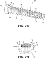
- FIGS. 7A-7E depict an alternative embodiment of a fixation screw assembly 105 for sacroiliac joint fusion according to other embodiments.
- Fixation screw assembly 105 is similar to the fixation assemblies previously discussed. Therefore, like features will be described with reference to similar numeral indicators.
- the fixation screw assembly 105 may be especially suitable as a sacroiliac fusion screw and is intended to increase the fixation achieved in sacroiliac fusion while decreasing the chance of migration.
- the sacroiliac fixation screw assembly 105 may be placed across the sacroiliac joint, and may traverse varying bone quality, including soft cancellous bone of the sacrum and hard cortical bone of the iliac wings.
- fixation screw assembly 105 including a dual inner diameter offers varying thread forms to address varying bone quality.
- the screw profile maximizes bone purchase when placed from a cortical to cancellous anatomy.
- the shaft 110 may include one or more biomaterial slots or windows 116, 118.
- the biomaterial windows 116, 118 may be filled with bone graft and cross either the sacroiliac joint for fusion or enhance fusion and prevent migration of the screw especially for longer screw lengths.
- a first biomaterial window 116 is similar to biomaterial window 16 discussed previously.
- a second biomaterial window 118 is provided closer to the distal portion 114 and is offset 90 degrees relative to the first biomaterial window 116.
- the biomaterial windows 116, 118 may be elongated having a length extending along the longitudinal axis of the device 102 greater than its respective width.
- the biomaterial windows 116, 118 are each in fluid communication with the cannulated opening 106.
- the biomaterial slots or windows 116, 118 may be filled with bone graft material, and are located along the length of the screw to thereby cross the sacroiliac joint for fusion. Additional windows 116, 118 be filled with bone graft to enhance fusion and prevent migration of the device 105 especially for longer screw lengths.
- the fixation screw assembly 105 also includes a washer member 150.
- the washer member 150 may resemble a ring-shaped or annular collar having a circular hole that can fit around the head member 130 of the fixation screw assembly 105.
- An inner surface of the washer member 150 may be substantially spherical and may correspond to a substantially spherical outer surface of the head member 130, thereby allowing for polyaxial rotation.
- Angulation may be needed when the fixation member 102 is implanted laterally because the anatomy of the iliac wings is sloped and may vary drastically between patients.
- the washer member 150 may have an inner annular lip 152. As best seen in the close-up cross section shown in FIG. 7B , when the washer member 150 is angled, a portion of the lip 152 on the top of the washer member 150 bottoms out on a groove 136 on the top of the spherical head member 130.
- the lip 152 on the washer member 150 coupled with the groove 136 on the screw head 130 may allow for maximum angulation while maintaining a portion of the washer member 150 below the equator of the screw shank 110 to prevent disassembly during implantation.
- Angulation may be important when the sacroiliac screw is implanted laterally to accommodate varying anatomy of the iliac wing. If only minimal angulation were provided by the implant, it is possible that a portion of the washer would not be seated in bone and would be free-floating in soft tissue.
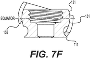
- Fig. 7F illustrates another embodiment of a washer member 151 in a cross sectional view.
- the washer member 151 can be slidably moved up and down the shaft 111 until it is locked around the head member 131.
- the washer member 151 may include one or more engagement surfaces or teeth 153 that can engage a surface of a bone member (e.g., an ilium) when the fixation screw assembly is implanted into bone.
- the teeth 153 may be provided on the bottom of the washer member 151 to grip into bone and provide tactile feedback to the user.
- the bottom teeth 153 of the washer member 150 may be tapered inward to allow the teeth 153 of the washer member 151 to recess into bone to provide a lower profile implant and maintain tactile feedback.
- the components of the fixation screw assembly 105 can be composed of various biocompatible materials.
- the materials include, but are not limited to, stainless steel, alloys, titanium, titanium based alloys or polymeric materials.
- the components of the fixation screw assembly 105 can be coated, roughened, or otherwise treated to improve osseointegration.
- the implant can be driven and inserted by traditional methods, image guided methods, or other using other minimally invasive procedures.
- the fixation screw assembly 105 may be implanted laterally or posteriorly, for example, to achieve a sacroiliac joint fusion.
- the screw assembly 160 may include one or more biomaterial slots or windows 162, 164, 166.
- the biomaterial windows 162, 164, 166 may be filled with bone graft and cross either the sacroiliac joint for fusion or enhance fusion and prevent migration of the screw especially for longer screw lengths.
- a second biomaterial window 164 is provided closer to the distal portion and is offset 90 degrees relative to the first biomaterial window 162.
- a third biomaterial window 166 is provided even closer to the distal end of the shaft and configured to have a smaller diameter than the first and second biomaterial windows.
- the biomaterial windows 162, 164, 166 may be elongated having a length extending along the longitudinal axis of the device greater than its respective width.
- the biomaterial windows 162, 164, 166 are each in fluid communication with the cannulated opening.
- the biomaterial slots or windows 162, 164, 166 may be filled with bone graft material, and are located along the length of the screw to thereby cross the sacroiliac joint for fusion.
- the biomaterial windows geometry is configured such that there is no gap between adjacent fusion areas. Since the sacroiliac joint is extremely variable in every patient and minimal in width, ensuring the fusion area crosses the joint requires no gap between adjacent fusion areas. In order to not compromise the screws strength, adjacent biomaterial windows are placed perpendicular to each other and are tapered in the overlapping section to maintain as much cross-sectional area as possible.
- FIG. 8B illustrates yet another embodiment of the screw assembly 168.
- the shaft is provided with two biomaterial windows 170, 172.
- the first biomaterial window 170 is positioned closer to the screw head 174 and the second biomaterial window 172 is positioned closer to the distal end of the shaft 176.
- the first and second biomaterial windows are perpendicular to one another and overlap.
- the shaft of the screw assembly is also cannulated.
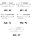
- FIGS. 9A-9E illustrate different configurations of the biomaterial windows on the shaft of screw assembly.
- FIG. 9A illustrates a shaft of screw assembly with three biomaterial windows, with two of the biomaterial windows in a first plane and a third biomaterial window offset by 90 degrees and configured to overlap with the first and second biomaterial windows.
- FIG. 9A illustrates a shaft of screw assembly with three biomaterial windows, with two of the biomaterial windows in a first plane and a third biomaterial window offset by 90 degrees and configured to overlap with the first and second biomaterial windows.
- FIG. 9B illustrates an embodiment in the which the shaft of a screw assembly is provided with a one elongated biomaterial window and two smaller circular or oval windows in a first plane. This embodiment also provides three additional circular or oval windows offset by 90 degrees form the first plane and configured to overlap the two circular windows of the first plane.
- FIG. 9C illustrates a shaft of a screw assembly having a first bullet nosed biomaterial window in a first plane and a second bullet nosed biomaterial window in a second plane offset by 90 degrees. The first bullet nosed biomaterial window and the second bullet nosed biomaterial window are configured to overlap with one another.
- FIGS. 9D and 9E are additional embodiments of a shaft of a screw assembly with a first and second biomaterial window offset by 90 degrees and overlapping. More specifically, as illustrated in FIGS. 9A, 9C and 9E , the biomaterial windows may be tapered. It should be noted the biomaterial window may be formed in any shape that would allow bone growth.
- the overlapping geometry of the biomaterial windows ensure that the fusion area will cross the joint regardless of insertion point or trajectory.
- the multiple fusion areas are intended to increase the chance of fusion along the length of the screw to decrease screw migration. This is advantageous to accommodate various patient anatomy, various bone quality, and various trajectories.
- the shaft of the screw assembly may also include several overlapping perpendicular slots intended to be filled with bone graft and cross either the sacroiliac joint for fusion or enhance fusion and prevent migration of the screw especially for longer screw lengths.
- the screw assemblies as illustrated in FIG. 8A and 8B are also cannulated.
- FIGS. 11A-11F illustrates the screw assembly manufactures by various methods. Specifically, FIG. 11A illustrates the screw assembly is a machined assembled screw. FIG. 11B is an acid etched screw. FIG. 11C is a machined screw with laser engravings. FIG. 11D is a machined screw that includes 3D printed bone plugs positioned within the biomaterial windows. FIG. 11E is a 3D printed screw. FIG. 11F is a 3D printed dowel with 3D printed porous plug that is positioned within the biomaterial windows.
- fixation screw assemblies and/or lag screw assemblies described above can be used in various surgical methods, and in particular, those involving fusion of the sacroiliac joint.
- the screw assemblies can be inserted minimally invasively, and can be inserted using one or more percutaneous delivery instruments.
- fixation screw assemblies 5a, 5b, and 5c can include bone engagement portions 8 having shafts 10 of variable lengths.
- FIGS. 12A, 12B, and 12C illustrate different approaches for positioning the screw assembly.
- FIG. 12A illustrates a method in which the screw assembly is positioned in a lateral approach.
- FIG. 12B illustrates a method in which the screw assembly is positioned in a posterior approach placing the screw assembly medial to lateral and
- FIG. 12C illustrates a method in which the screw is positioned with a posterior approach placing the screw lateral to medial.
- the processes encompassed by this application are not limited to the steps described above.
- an additional step can be provided in which biologic material is introduced into the fixation screw assembly (e.g., via a biomaterial window), thereby aiding in the fusion of the sacroiliac joint.
Abstract
Description
- This Patent Application is continuation-in-part of
U.S. Patent Application Serial No. 15/795,920 filed on October 27,2017 U.S. Patent Application No. 14/563,697, filed December 8, 2014 U.S. Patent Application No. 13/184,026, filed on July 15, 2011 - The present application generally relates to fixation implants, and in particular, screw implants.
- In vertebrate anatomy, the sacrum is a large, triangular bone that lies at the bottom of the lumbar spine, where it connects with the L5 vertebra. The sacrum lies adjacent to two hip bones, known as the right ilium and left ilium. The sacrum connects with these bones via joints known as sacroiliac joints (or SI joints).
- The sacroiliac joints assist in the transmission of forces from the spine to the lower extremities. Degeneration of the sacroiliac joints can occur due to diseases, such as degenerative sacroiliitis and inflammatory sacroiliitis, as well as due to normal aging and trauma. One type of treatment for a degenerated sacroiliac joint is fusion of the joint, which ultimately relieves pain.
- Thus, there remains a need for improved implants that assist in the fusion of sacroiliac joints.
- Various fixation implants are provided for assisting in bone fusion. In some embodiments, an implant for implanting across a sacroiliac joint is provided. The implant includes a bone engaging portion comprising a shaft and a head portion, wherein the shaft includes a plurality of threads. The shaft includes a biomaterial window for receiving biological material to assist in fusion of the sacroiliac joint. The implant further includes a flexible washer member configured to be in a locking configuration around the head portion, wherein the washer member includes a plurality of slits that accommodate expansion of the washer member around the head portion and one or more engagement members for engaging a bone surface. The washer member is capable of polyaxial movement relative to a longitudinal axis of the bone engaging portion.
- In some embodiments, an implant for implant across a sacroiliac joint comprises a bone engaging portion comprising a shaft and a head portion, wherein the shaft includes a plurality of threads. The shaft can have a length of between about 25 mm and 110 mm for extending across at least a portion of an ilium, a sacroiliac joint and sacrum. The implant further includes a flexible washer member configured to be in a locking configuration around the head portion. The washer member is capable of expansion around the head portion and includes one or more engagement members for engaging a bone surface. The washer member is capable of polyaxial movement relative to a longitudinal axis of the bone engagement portion.
- According to some embodiments, a fixation screw assembly for fusing a sacroiliac joint includes a fixation member and a washer member. The fixation member includes a head member and a bone-engaging portion coupled to the head member. The head member having a generally spherical outer surface and a groove. The washer member has an inner annular lip. The washer member is operatively coupled to the fixation member around the head member. An inner surface of the washer member is generally spherical and corresponding to the generally spherical outer surface of the head member. The washer member is capable of polyaxial movement relative to a longitudinal axis of the fixation member. When the washer member is sufficiently angled relative to the longitudinal axis of the fixation member, the lip of the washer member bottoms out on the groove of the head member.
- According to yet other embodiments, a fixation screw assembly for fusing a sacroiliac joint includes a fixation member and a washer member. The fixation member includes a head member and a bone-engaging portion including a plurality of threads coupled to the head member. The head member has a generally spherical outer surface. The bone-engaging portion includes a dual inner diameter including a first portion with shallow threads and a second portion with deep threads. The washer member is operatively coupled to the fixation member around the head member. An inner surface of the washer member is generally spherical and corresponds to the generally spherical outer surface of the head member. The washer member is capable of polyaxial movement relative to a longitudinal axis of the fixation member.
- In some embodiments, a method of fusing a sacroiliac joint is provided. The method comprises forming an incision in a patient; delivering a fixation screw assembly through the incision and laterally toward an ilium, wherein the fixation screw assembly includes a washer member and a bone engagement portion comprising a shaft and head member, wherein the washer member is operatively coupled to the bone engagement portion around the head member, and wherein the washer member is capable of polyaxial movement relative to a longitudinal axis of the bone engagement portion; driving the fixation screw assembly through the ilium, across a sacroiliac joint and into a sacrum until the washer member engages a surface of the ilium; and maintaining the fixation screw assembly in place to assist in fusion of the sacroiliac joint.
-
-
FIG. 1A is a front view of a fixation screw assembly for sacroiliac joint fusion according to some embodiments. -
FIG. 1B is a front view of the fixation screw assembly inFIG. 1A with a washer in a locked configuration according to some embodiments. -
FIG. 2 is a close-up cross-sectional view of a washer member angled relative to the bone-engaging portion according some embodiments. -
FIG. 3 is a front view of a fixation screw assembly having a biomaterial window according to some embodiments. -
FIG. 4 is a front view of a lag screw assembly for sacroiliac joint fusion according to some embodiments. -
FIG. 5 is a front view of a lag screw assembly having a biomaterial window according to some embodiments. -
FIG. 6 illustrates multiple fixation screw assemblies assisting in fusion of the sacroiliac joint according to some embodiments. -
FIGS. 7A-7F illustrate various view of an alternative embodiment of a fixation screw assembly. -
FIGS. 8A and 8B illustrate alternative embodiments of a fixation screw assembly. -
FIGS. 9A-9E illustrates different embodiments of the positioning of biomaterial windows on a shaft of the fixation screw assembly. -
FIG. 10 illustrates a screw assembly with an acid etching treatment. -
FIGS. 11A-11F illustrates screw assemblies manufactured by various methods. -
FIGS. 12A-12C illustrate the positioning of the screw assembly within the body using different methods. - Detailed embodiments of the invention are disclosed herein; however, it is to be understood that the disclosed embodiments are merely exemplary of the invention, which may be embodied in various forms. Therefore, specific structural and functional details disclosed herein are not to be interpreted as limiting, but merely as a basis for the claims and as a representative basis for teaching one skilled in the art to variously employ the present invention in virtually any appropriately detailed structure.
- The present application generally relates to fixation implants, and in particular, screw implants. The screw implants can be used to assist in the fusion of the sacroiliac joint. In some embodiments, the screw implants can be introduced through an ilium, past a degenerated sacroiliac joint and into the sacrum. After implantation, the screw implants remain in place and assist in the fusion of the sacroiliac joint.
- One of the difficulties with implanting a screw into a bone member is inadvertent back out. For the ilia, which are wing-shaped, the inadvertent back out of fixation screws presents a challenging problem due to the curved surfaces. To address this problem, the screw implants of the present application advantageously provide a mechanism that prevents or reduces the risk of inadvertent back out from an ilium. In particular, the screw implants include an easily assembled washer member that assists in preventing inadvertent back out of the screw implant. The washer member is advantageously designed to have flexibility to conform to the ilium contour when the screw implant is implanted in the ilium.
-
FIG. 1A is a front view of a fixation screw assembly for sacroiliac joint fusion according to some embodiments. Thefixation screw assembly 5 includes a bone-engagingportion 8 comprising ashaft 10 operably coupled to ahead member 30. Thefixation screw assembly 5 also includes awasher member 50 that can be upwardly loaded via theshaft 10 until it is positioned proximate thehead member 30. Once proximate thehead member 30, thewasher member 50 can be forced upwardly (e.g., using an instrument) around thehead member 30, where it is placed into a locked configuration in which it is securely fastened around thehead member 30. Once in the locked configuration, thefixation screw assembly 5 can be inserted into a bone member, such as an ilium, whereby it can assist in fusion (e.g., of the sacroiliac joint). - The
shaft 10 of the bone-engagingportion 8 includes a plurality ofthreads 12. As shown inFIG. 1A , thethreads 12 extend along at least a majority of the length of theshaft 10. In other embodiments, thethreads 12 extend only along a minority portion of theshaft 10. In some embodiments, thethreads 12 of the bone-engagingportion 8 of theshaft 10 are dual lead threads, although any type of thread may be used to facilitate the insertion of bone-engagingportion 8 into bone. - The
shaft 10 of the bone-engagingportion 8 also includes adistal portion 14 which serves as the lead end for entry into a bone member. Thedistal portion 14 can be tapered to assist in the insertion process. In addition, at least one flute can be provided on thedistal portion 14 or along any other part of the bone-engagingportion 8 in order to clear any chips, dust, or debris generated when the bone-engagingportion 8 is implanted into bone tissue. In addition, in some embodiments, theshaft 10 can be cannulated to receive a guide wire or other type of instrument to assist in implantation. - In some embodiments, the
shaft 10 of thefixation screw assembly 5 is inserted through multiple bone members (e.g., through an ilium and sacrum) to assist in fusion. In order to accommodate insertion through multiple bone members, theshaft 10 advantageously has a length of between about 20 mm to about 110 mm, or between about 25 mm to about 110 mm. In some embodiments, theshaft 10 of thefixation screw assembly 5 also has a diameter or width of between about 6 mm and about 14 mm, or between about 8 mm and 12 mm. These ranges advantageously allow biologic material to be packed within the interior of theshaft 10, as discussed in more detail below. As shown inFIGS. 1A and 1B , theshaft 10 of thefixation screw assembly 5 can remain generally constant in diameter along a majority of the length of theassembly 5, thereby advantageously allowing for optimal screw positioning when the bone screw is inserted into a predetermined area in bone tissue. However, in other embodiments, theshaft 10 can taper, such that its diameter becomes narrower towards a distal end of theshaft 10. - The
shaft 10 is operably connected to ahead member 30. Theshaft 10 transitions into thehead member 30 via aneck portion 32. In some embodiments, theneck portion 32 has a diameter or width equal to or less than that of the shaft. Within atop portion 34 of thehead member 30 is an engagement portion configured to receive a driving instrument, such as a screw driver (not shown). The screw driver can be used to drive thefixation screw assembly 5 into one or more bone members, such as the ilium and/or sacrum. - The
fixation screw assembly 5 includes awasher member 50 that is easily assembled into a locked configuration with the bone-engagingportion 8. In some embodiments, thewasher member 50 resembles a ring-shaped or annular collar having a circular hole that can fit around theshaft 10 of thefixation screw assembly 5. Thewasher member 50 can be slidably moved up and down theshaft 10 until it is locked around thehead member 30. Thewasher member 50 includes one ormore slits 52 that can accommodate expansion of thewasher member 50 over thehead member 30, thereby placing thewasher member 50 in an assembled and locked configuration around thehead member 30. In some embodiments, thewasher member 50 is pre-assembled in a locked configuration around thehead member 30 of the fixation screw assembly 5 (as shown inFIG. 1B ). On an end of thewasher member 50 opposite from theslits 52, thewasher member 50 includes one or more engagement surfaces orteeth 54 that can engage a surface of a bone member (e.g., an ilium) when thefixation screw assembly 5 is implanted into bone. - Advantageously, the
washer member 50 is flexible and polyaxial relative to the bone-engagingportion 8. In other words, thewasher member 50 can be angled, rotated or swiveled in multiple directions, as best shown inFIG. 2 . In some embodiments, thewasher member 50 can have a central axis that is positioned at an angle of between about 0 and about 30 degrees, or between about 0 and 24 degrees, relative to the longitudinal axis of the bone-engagingportion 8. - The components of the
fixation screw assembly 5 can be composed of various biocompatible materials. The materials include, but are not limited to, stainless steel, alloys, titanium, titanium based alloys or polymeric materials. - In operation, when a lateral compressive force is applied to the
fixation screw assembly 5, the bone-engagingportion 8 is driven through a bone member, such as the ilium. As the bone-engagingportion 8 is driven laterally, thewasher member 50 also engages a surface of the bone member (as shown inFIG. 6 ). Thewasher member 50 can engage the bone member at a different angle from the bone-engagingportion 8. This relative angulation advantageously allows thewasher member 50 to engage a curved surface of a bone member (e.g., the ilium) with ease, even when the bone-engagingportion 8 is at a different angle. Furthermore, the compressive force of anangled washer member 50 against thehead member 30 of the bone-engagingportion 8 also advantageously prevents back out of an implantedfixation screw assembly 5. -
FIG. 2 is a close-up cross-sectional view of a washer member angled relative to the bone-engaging portion according some embodiments. From this view, the angulation of thewasher member 50 relative to thehead member 30 of the bone-engagingportion 8 is visible. Also, thephysical interface 76 between thewasher member 50 and thehead member 30 is also shown. When a force is applied, thewasher member 50 will be placed in a compressive force with thehead member 30 at theinterface 76, thereby helping to prevent inadvertent back out of the bone-engagingportion 8 from a bone member. -
FIG. 3 is a front view of a fixation screw assembly having a biomaterial window according to some embodiments. Thefixation screw assembly 5 is similar to the assembly inFIGS. 1A and 1B , except that it also includes abiomaterial window 16. Biological material, including natural and synthetic material, can be inserted into thebiomaterial window 16 to assist in bone growth and fusion. In some embodiments, the biological material comprises a rectangular window, as shown in the illustrated embodiment. The biomaterial window advantageously has a length of between about 1/4 to 4/5 of the length of theshaft 10, such that it can expand across multiple bone members and/or joints if desired. In some embodiments, the biomaterial window has a length of between about 1/3 to 1/2 of the length of theshaft 10. -
FIG. 4 is a front view of a lag screw assembly for sacroiliac joint fusion according to some embodiments. The lag screw assembly 15 includes many of the features of thefixation screw assembly 5 inFIG. 1 , including a bone-engagingportion 8, a head portion and awasher 50 configured to lock around the head portion. However, unlike thefixation screw assembly 5, the lag screw assembly 15 further includes a substantially smooth,non-threaded portion 80 that extends between the bone-engagingportion 8 and the head portion. In some embodiments, the threaded portion and the non-threaded portion of the lag screw assembly form a continuous, monolithic component. -
FIG. 5 is a front view of a lag screw assembly having a biomaterial window according to some embodiments. As shown in the illustrated figure, the lag screw assembly 15 includes abiomaterial window 16 through which biologic material can be deposited. Advantageously, the lag screw assembly 15 can be designed such that thebiomaterial window 16 extends across both the threaded portion and thenon-threaded portion 80. In other embodiments, thebiomaterial window 16 need only extend within thenon-threaded portion 80, such that the threads of the lag screw assembly remain intact. However, one skilled in the art will appreciate that the biomaterial window can also extend into the threaded portion of the bone-engagingportion 8 if desired. -
FIGS. 7A-7E depict an alternative embodiment of afixation screw assembly 105 for sacroiliac joint fusion according to other embodiments.Fixation screw assembly 105 is similar to the fixation assemblies previously discussed. Therefore, like features will be described with reference to similar numeral indicators. Thefixation screw assembly 105 may be especially suitable as a sacroiliac fusion screw and is intended to increase the fixation achieved in sacroiliac fusion while decreasing the chance of migration. The sacroiliacfixation screw assembly 105 may be placed across the sacroiliac joint, and may traverse varying bone quality, including soft cancellous bone of the sacrum and hard cortical bone of the iliac wings. Oftentimes bone screws do not address the drastic change in bone quality between sacrum and ilium causing haloing of screws on the sacral cancellous side. Thefixation screw assembly 105 described herein including a dual inner diameter offers varying thread forms to address varying bone quality. In addition, the screw profile maximizes bone purchase when placed from a cortical to cancellous anatomy. Although generally described with reference to sacroiliac fusion, it will be appreciated that thefixation screw assembly 105 may be utilized for other bone screw applications. -
FIG. 7A provides a perspective view of theassembly 105. Thefixation screw assembly 105 includes afixation member 102 and awasher member 150. Thefixation member 102 extends from aproximal portion 104 to adistal portion 114. Thefixation member 102 includes a bone-engagingportion 108 including a plurality ofthreads 112. Thefixation member 102 comprises a shank orshaft 110 operably coupled to ahead member 130, for example, through aneck portion 132. Thehead member 30 includes anengagement portion 34. Theengagement portion 34 may include an internally threaded portion and/or a socket portion (e.g., hexalobular), configured to receive a driving instrument, such as a screw driver (not shown). The screw driver can be used to drive thefixation screw assembly 105 into one or more bone members, such as the ilium and/or sacrum. The hexalobular driving feature may help to prevent stripping of the screw or instrument stripping especially because thefixation member 102 is going through hard cortical bone requiring large forces to drive the screw. - In this embodiment, the
shaft 110 is cannulated with anopening 106 extending from theproximal portion 104 to thedistal portion 114 of thefixation member 102, and may thereby receive a guide wire or other type of instrument to assist in implantation. When cannulated, thefixation assembly 105 may be inserted in a minimally invasive fashion. - The
shaft 110 may include one or more biomaterial slots orwindows biomaterial windows first biomaterial window 116 is similar tobiomaterial window 16 discussed previously. As best seen in the cross-sectional view shown inFIG. 7E , asecond biomaterial window 118 is provided closer to thedistal portion 114 and is offset 90 degrees relative to thefirst biomaterial window 116. Thebiomaterial windows device 102 greater than its respective width. Thebiomaterial windows opening 106. The biomaterial slots orwindows Additional windows device 105 especially for longer screw lengths. - As best seen in the close-up perspective view in
FIG. 7C and the close-up cross-sectional view inFIG. 7D , theshaft 110 of thefixation member 102 may include a dual inner diameter. A dualinner diameter screw 102 provides forshallow threads 124 anddeep threads 126 with aconstant pitch 128 and constant outer diameter on two regions of thebone screw shaft 110. The portion ofthreads 112 at theproximal portion 104 of the screw 102 (intended to fixate cortical bone) hasshallow threads 124 while the portion ofthreads 112 at the distal tip of the screw 102 (intended to fixate cancellous bone) hasdeep threads 126. Thedeep threads 126 combined with the consistency inpitch 128 allow for more bone to be located within thedeep threads 126 than within theshallow threads 124, thereby providing increased bone purchase, increased resistance to pullout, and/or increased resistance to migration in softer less dense bone. The dual inner diameter thread may provide for increased fixation, decreased migration, decreased pullout, and decreased haloing of thedevice 105. This is advantageous when there is a drastic change in bone quality at various parts along the screw length. The feature of varying inner diameter with a constant outer diameter allows forshallow threads 124 at theproximal portion 104 anddeep threads 126 at thedistal portion 114, which may be ideal for crossing from cortical to cancellous bone. - The
fixation screw assembly 105 also includes awasher member 150. Thewasher member 150 may resemble a ring-shaped or annular collar having a circular hole that can fit around thehead member 130 of thefixation screw assembly 105. An inner surface of thewasher member 150 may be substantially spherical and may correspond to a substantially spherical outer surface of thehead member 130, thereby allowing for polyaxial rotation. Angulation may be needed when thefixation member 102 is implanted laterally because the anatomy of the iliac wings is sloped and may vary drastically between patients. - The
washer member 150 may have an innerannular lip 152. As best seen in the close-up cross section shown inFIG. 7B , when thewasher member 150 is angled, a portion of thelip 152 on the top of thewasher member 150 bottoms out on agroove 136 on the top of thespherical head member 130. Thelip 152 on thewasher member 150 coupled with thegroove 136 on thescrew head 130 may allow for maximum angulation while maintaining a portion of thewasher member 150 below the equator of thescrew shank 110 to prevent disassembly during implantation. Angulation may be important when the sacroiliac screw is implanted laterally to accommodate varying anatomy of the iliac wing. If only minimal angulation were provided by the implant, it is possible that a portion of the washer would not be seated in bone and would be free-floating in soft tissue. - The
washer member 150 can be angled, rotated or swiveled in multiple directions. Thewasher member 150 can be slidably moved up and down theshaft 110 until it is locked around thehead member 130. Thewasher member 150 may include one or more engagement surfaces orteeth 154 that can engage a surface of a bone member (e.g., an ilium) when the fixation screw assembly 1055 is implanted into bone. Theteeth 154 may be provided on the bottom of thewasher member 150 to grip into bone and provide tactile feedback to the user. Thebottom teeth 154 of thewasher member 150 may be tapered inward to allow theteeth 154 of thewasher member 150 to recess into bone to provide a lower profile implant and maintain tactile feedback. Similarly, the bottom outside outer surface of thewasher member 150 may be tapered inward to allow theteeth 154 of thewasher member 150 to sometimes recess into bone to provide a lower profile implant but maintain tactile feedback. The outer diameter of thewasher member 150 is larger than the outer diameter of thehead member 130 so a portion of thewasher teeth 154 always contact bone. Thewasher member 150 may be assembled onto thefixation member 102 from the top of thefixation member 102 to prevent disassembly of thewasher member 150 from the fixation member if theassembly 105 is removed after implantation. In this manner, thewasher member 150 cannot disassemble from thescrew shank 110 during removal since thewasher member 150 is assembled onto thescrew shank 110 from the top. -
Fig. 7F illustrates another embodiment of awasher member 151 in a cross sectional view. Thewasher member 151 can be slidably moved up and down theshaft 111 until it is locked around thehead member 131. Thewasher member 151 may include one or more engagement surfaces orteeth 153 that can engage a surface of a bone member (e.g., an ilium) when the fixation screw assembly is implanted into bone. Theteeth 153 may be provided on the bottom of thewasher member 151 to grip into bone and provide tactile feedback to the user. Thebottom teeth 153 of thewasher member 150 may be tapered inward to allow theteeth 153 of thewasher member 151 to recess into bone to provide a lower profile implant and maintain tactile feedback. Similarly, the bottom outside outer surface of thewasher member 151 may be tapered inward to allow theteeth 153 of thewasher member 151 to recess into bone to provide a lower profile implant but maintain tactile feedback. The configuration of thewasher member 151 allows for extreme angulation. A portion of the washer member is configured to always remain below the equator of the screw head when maximum angulation is achieved to prevent disassembly during implantation. Theteeth 153 on the bottom surface of thewasher member 151 also provides tactile feedback to the user. The outer diameter of the washer member is larger than the outer diameter of the screw so a portion of thewasher teeth 153 always contact bone. - Similar to
assembly 105, the components of thefixation screw assembly 105 can be composed of various biocompatible materials. The materials include, but are not limited to, stainless steel, alloys, titanium, titanium based alloys or polymeric materials. The components of thefixation screw assembly 105 can be coated, roughened, or otherwise treated to improve osseointegration. The implant can be driven and inserted by traditional methods, image guided methods, or other using other minimally invasive procedures. Thefixation screw assembly 105 may be implanted laterally or posteriorly, for example, to achieve a sacroiliac joint fusion. - In another embodiment as shown in
FIG. 8A , thescrew assembly 160 may include one or more biomaterial slots orwindows biomaterial windows FIG. 8A , asecond biomaterial window 164 is provided closer to the distal portion and is offset 90 degrees relative to thefirst biomaterial window 162. Athird biomaterial window 166 is provided even closer to the distal end of the shaft and configured to have a smaller diameter than the first and second biomaterial windows. Thebiomaterial windows biomaterial windows windows -
Figure 8B illustrates yet another embodiment of thescrew assembly 168. In this embodiment the shaft is provided with twobiomaterial windows first biomaterial window 170 is positioned closer to thescrew head 174 and thesecond biomaterial window 172 is positioned closer to the distal end of theshaft 176. The first and second biomaterial windows are perpendicular to one another and overlap. The shaft of the screw assembly is also cannulated.FIGS. 9A-9E illustrate different configurations of the biomaterial windows on the shaft of screw assembly.FIG. 9A illustrates a shaft of screw assembly with three biomaterial windows, with two of the biomaterial windows in a first plane and a third biomaterial window offset by 90 degrees and configured to overlap with the first and second biomaterial windows.FIG. 9B illustrates an embodiment in the which the shaft of a screw assembly is provided with a one elongated biomaterial window and two smaller circular or oval windows in a first plane. This embodiment also provides three additional circular or oval windows offset by 90 degrees form the first plane and configured to overlap the two circular windows of the first plane.FIG. 9C illustrates a shaft of a screw assembly having a first bullet nosed biomaterial window in a first plane and a second bullet nosed biomaterial window in a second plane offset by 90 degrees. The first bullet nosed biomaterial window and the second bullet nosed biomaterial window are configured to overlap with one another.FIGS. 9D and 9E are additional embodiments of a shaft of a screw assembly with a first and second biomaterial window offset by 90 degrees and overlapping. More specifically, as illustrated inFIGS. 9A, 9C and 9E , the biomaterial windows may be tapered. It should be noted the biomaterial window may be formed in any shape that would allow bone growth. - The overlapping geometry of the biomaterial windows ensure that the fusion area will cross the joint regardless of insertion point or trajectory. The multiple fusion areas are intended to increase the chance of fusion along the length of the screw to decrease screw migration. This is advantageous to accommodate various patient anatomy, various bone quality, and various trajectories. The shaft of the screw assembly may also include several overlapping perpendicular slots intended to be filled with bone graft and cross either the sacroiliac joint for fusion or enhance fusion and prevent migration of the screw especially for longer screw lengths. The screw assemblies as illustrated in
FIG. 8A and 8B are also cannulated. -
FIG. 10 illustrates a screw assembly that is configured with a laser engraving treatment. A nanotube treatment may be added to the screw to improve osseointegration and antimicrobial properties. The subtractive treatments may also be applied to the minor diameter of the threads as to not compromise structural integrity of the screw. The treatment may be offset from the sharp edges of the biomaterial windows to reduce the likelihood of crack propagation. The subtractive treatment may be applied along the entire length of the screw or only at the portion of the screw that comes in contact with sacral bone. The subtractive treatment may be omitted near the slotted portion of the screw. -
FIGS. 11A-11F illustrates the screw assembly manufactures by various methods. Specifically,FIG. 11A illustrates the screw assembly is a machined assembled screw.FIG. 11B is an acid etched screw.FIG. 11C is a machined screw with laser engravings.FIG. 11D is a machined screw that includes 3D printed bone plugs positioned within the biomaterial windows.FIG. 11E is a 3D printed screw.FIG. 11F is a 3D printed dowel with 3D printed porous plug that is positioned within the biomaterial windows. - The fixation screw assemblies and/or lag screw assemblies described above can be used in various surgical methods, and in particular, those involving fusion of the sacroiliac joint. The screw assemblies can be inserted minimally invasively, and can be inserted using one or more percutaneous delivery instruments.
- In some embodiments, the application encompasses surgical methods including:
- a. forming an incision in a patient, wherein the incision has a width of between about 7 mm and 33 mm;
- b. inserting a guide sleeve percutaneously through the incision to provide a lateral approach for inserting a fixation screw assembly;
- c. inserting a fixation screw assembly through the guide sleeve, wherein the fixation screw assembly includes a flexible washer member and a bone engagement portion comprising a shaft and head portion, wherein the washer member is pre-assembled in a locked configuration around the head portion, and wherein the washer member is configured to move polyaxially relative to the shaft and head portion;
- d. using a screw driver to drive the fixation screw assembly through an ilium, sacroiliac joint and sacrum;
- e. driving the fixation screw assembly through the bone members until the washer member compresses against a surface of the ilium, thereby helping to prevent back out of the fixation screw;
- f. maintaining the fixation screw in place to assist in fusion of the sacroiliac joint.
- The process described above can be repeated multiple times until two, three or more fixation screw assemblies are deposited across the sacroiliac joint. Advantageously, in some embodiments, at least two fixation screw assemblies are provided to stabilize and assist in the fusion of the sacroiliac joint. In some embodiments, at least three fixation screw assemblies are provided, as shown in
FIG. 6 . As shown in the illustrated embodiment, thefixation screw assemblies bone engagement portions 8 havingshafts 10 of variable lengths. For example, whilefixation screw assemblies 5a and 5c haveshafts 10 that are long enough to be implanted through a portion of an ilium 7, sacroiliac joint 11 and sacrum 9,fixation screw assembly 5b has a relatively shorter shaft that passes only through a portion of the ilium 7. - While the process detailed above describes a lateral approach, one skilled in the art will appreciate that insertion of the fixation screw assembly and/or lag screw assemblies can be performed via other approaches as well, including anteriorly and posteriorly. For instance,
FIGS. 12A, 12B, and 12C illustrate different approaches for positioning the screw assembly.FIG. 12A illustrates a method in which the screw assembly is positioned in a lateral approach.FIG. 12B illustrates a method in which the screw assembly is positioned in a posterior approach placing the screw assembly medial to lateral andFIG. 12C illustrates a method in which the screw is positioned with a posterior approach placing the screw lateral to medial. In addition, the processes encompassed by this application are not limited to the steps described above. For example, an additional step can be provided in which biologic material is introduced into the fixation screw assembly (e.g., via a biomaterial window), thereby aiding in the fusion of the sacroiliac joint. - It will be apparent to those skilled in the art that various modifications and variations can be made in the present invention without departing from the scope or spirit of the invention. Moreover, the improved implants and related methods of use need not feature all of the objects, advantages, features and aspects discussed above. Thus, for example, those skilled in the art will recognize that the invention can be embodied or carried out in a manner that achieves or optimizes one advantage or a group of advantages as taught herein without necessarily achieving other objects or advantages as may be taught or suggested herein. In addition, while a number of variations of the invention have been shown and described in detail, other modifications and methods of use, which are within the scope of this invention, will be readily apparent to those of skill in the art based upon this disclosure. It is contemplated that various combinations or subcombinations of these specific features and aspects of embodiments may be made and still fall within the scope of the invention. Accordingly, it should be understood that various features and aspects of the disclosed embodiments can be combined with or substituted for one another in order to form varying modes of the discussed spacer implants. Thus, it is intended that the present invention cover the modifications and variations of this invention provided that they come within the scope of the appended claims or their equivalents. The invention could be defined inter alia by the following examples:
- 1. A fixation screw assembly for fusing a sacroiliac joint comprising: a fixation member including a head member and a bone-engaging portion coupled to the head member, the head member having a generally spherical outer surface and a groove; and a washer member having an inner annular lip, wherein the washer member is operatively coupled to the fixation member around the head member, an inner surface of the washer member being generally spherical and corresponding to the generally spherical outer surface of the head member, wherein the washer member is capable of polyaxial movement relative to a longitudinal axis of the fixation member, wherein when the washer member is sufficiently angled relative to the longitudinal axis of the fixation member, wherein the bone engaging portion includes a first biomaterial window and a second biomaterial window, the first biomaterial window and the second biomaterial window are configured perpendicular to one another and overlap.
- 2. The assembly of example 1, wherein the fixation member is cannulated with an opening extending from a proximal portion to a distal portion of the fixation member.
- 3. The assembly of example 1, wherein the shaft includes a third biomaterial window offset 90 degrees relative to the first biomaterial window.
- 4. The assembly of example 3, wherein the first, second and third biomaterial windows are each in fluid communication with the cannulated opening.
- 5. The assembly of example 3, wherein the first and second biomaterial window overlap and the second and third biomaterial window overlap.
- 6. The assembly of example 5, wherein the fixation member includes a dual inner diameter including a first portion with shallow threads and a second portion with deep threads.
- 7. The assembly of example 1, wherein the fixation member is 3D printed.
- 8. The assembly of example 1, wherein the washer member is configured to be angled, rotated or swiveled in multiple directions.
- 9. The assembly of example 1, wherein the washer member includes one or more engagement surfaces configured to engage adjacent bone.
- 10. The assembly of example 9, wherein the engagement surfaces are teeth that are tapered inward to allow the teeth to recess into bone.
- 11. A fixation screw assembly for fusing a sacroiliac joint comprising: a fixation member including a head member and a bone-engaging portion including a plurality of threads coupled to the head member, the head member having a generally spherical outer surface, wherein the bone-engaging portion includes a dual inner diameter including a first portion with shallow threads and a second portion with deep threads; and a washer member operatively coupled to the fixation member around the head member, an inner surface of the washer member being generally spherical and corresponding to the generally spherical outer surface of the head member, wherein the washer member is capable of polyaxial movement relative to a longitudinal axis of the fixation member wherein the bone engaging portion includes a first biomaterial window and a second biomaterial windown offset 90 degrees relative to the first biomaterial window, wherein the first biomaterial window and the second biomaterial window overlap.
- 12. The assembly of example 11, wherein the fixation member is cannulated with an opening extending from a proximal portion to a distal portion of the fixation member.
- 13. The assembly of example 11, wherein the shaft includes a third biomaterial window offset 90 degrees relative to the second biomaterial window and overlaps the second biomaterial window.
- 14. The assembly of example 13, wherein the first, second and third biomaterial windows are each in fluid communication with the cannulated opening.
- 15. The assembly of example 11, wherein the head member of the fixation member includes a groove at a proximal-most end of the head member and the washer member includes a lip at a proximal-most end of the washer member.
- 16. The assembly of example 15, wherein when the washer member is sufficiently angled relative to the longitudinal axis of the fixation member, the lip of the washer member bottoms out on the groove of the head member.
- 17. The assembly of example 11, wherein the fixation member is 3D printed.
- 18. The assembly of example 11, wherein the washer member is configured to be angled, rotated or swiveled in multiple directions.
- 19. The assembly of example 11, wherein the washer member includes one or more engagement surfaces configured to engage adjacent bone.
- 20. The assembly of example 19, wherein the engagement surfaces are teeth that are tapered inward to allow the teeth to recess into bone.
Claims (10)
- A fixation screw assembly for fusing a sacroiliac joint comprising:a fixation member including a head member and a bone-engaging portion coupled to the head member, the head member having a generally spherical outer surface and a groove; anda washer member having an inner annular lip, wherein the washer member is operatively coupled to the fixation member around the head member, an inner surface of the washer member being generally spherical and corresponding to the generally spherical outer surface of the head member, wherein the washer member is capable of polyaxial movement relative to a longitudinal axis of the fixation member,wherein when the washer member is sufficiently angled relative to the longitudinal axis of the fixation member,wherein the bone engaging portion includes a first biomaterial window and a second biomaterial window, the first biomaterial window and the second biomaterial window are configured perpendicular to one another and overlap.
- The assembly of claim 1, wherein the fixation member is cannulated with an opening extending from a proximal portion to a distal portion of the fixation member.
- The assembly of claim 1, wherein the shaft includes a third biomaterial window offset 90 degrees relative to the first biomaterial window.
- The assembly of claim 3, wherein the first, second and third biomaterial windows are each in fluid communication with the cannulated opening.
- The assembly of claim 3, wherein the first and second biomaterial window overlap and the second and third biomaterial window overlap.
- The assembly of claim 5, wherein the fixation member includes a dual inner diameter including a first portion with shallow threads and a second portion with deep threads.
- The assembly of claim 1, wherein the fixation member is 3D printed.
- The assembly of claim 1, wherein the washer member is configured to be angled, rotated or swiveled in multiple directions.
- The assembly of claim 1, wherein the washer member includes one or more engagement surfaces configured to engage adjacent bone.
- The assembly of claim 9, wherein the engagement surfaces are teeth that are tapered inward to allow the teeth to recess into bone.
Applications Claiming Priority (1)
| Application Number | Priority Date | Filing Date | Title |
|---|---|---|---|
| US16/112,838 US10925653B2 (en) | 2011-07-15 | 2018-08-27 | Screw implants for bone fusion |
Publications (2)
| Publication Number | Publication Date |
|---|---|
| EP3616634A1 true EP3616634A1 (en) | 2020-03-04 |
| EP3616634B1 EP3616634B1 (en) | 2023-03-08 |
Family
ID=67770415
Family Applications (1)
| Application Number | Title | Priority Date | Filing Date |
|---|---|---|---|
| EP19193725.9A Active EP3616634B1 (en) | 2018-08-27 | 2019-08-27 | Screw implants for bone fusion |
Country Status (2)
| Country | Link |
|---|---|
| EP (1) | EP3616634B1 (en) |
| JP (1) | JP6979051B2 (en) |
Cited By (13)
| Publication number | Priority date | Publication date | Assignee | Title |
|---|---|---|---|---|
| WO2021204905A1 (en) * | 2020-04-08 | 2021-10-14 | Spinewelding Ag | Bone implant |
| WO2021204907A1 (en) * | 2020-04-08 | 2021-10-14 | Spinewelding Ag | Surgical system comprising an implant and a bone anchor suitable for fixating the implant relative to bone tissue |
| WO2021204908A1 (en) | 2020-04-08 | 2021-10-14 | Spinewelding Ag | Fenestrated bone anchor |
| US11234830B2 (en) | 2019-02-14 | 2022-02-01 | Si-Bone Inc. | Implants for spinal fixation and or fusion |
| US11291485B2 (en) | 2012-05-04 | 2022-04-05 | Si-Bone Inc. | Fenestrated implant |
| US11337821B2 (en) | 2012-03-09 | 2022-05-24 | Si-Bone Inc. | Integrated implant |
| US11369419B2 (en) | 2019-02-14 | 2022-06-28 | Si-Bone Inc. | Implants for spinal fixation and or fusion |
| US11471286B2 (en) | 2012-03-09 | 2022-10-18 | Si-Bone Inc. | Systems, devices, and methods for joint fusion |
| US11571245B2 (en) | 2019-11-27 | 2023-02-07 | Si-Bone Inc. | Bone stabilizing implants and methods of placement across SI joints |
| US11633292B2 (en) | 2005-05-24 | 2023-04-25 | Si-Bone Inc. | Apparatus, systems, and methods for the fixation or fusion of bone |
| US11684378B2 (en) | 2014-09-18 | 2023-06-27 | Si-Bone Inc. | Implants for bone fixation or fusion |
| US11752011B2 (en) | 2020-12-09 | 2023-09-12 | Si-Bone Inc. | Sacro-iliac joint stabilizing implants and methods of implantation |
| US11877756B2 (en) | 2017-09-26 | 2024-01-23 | Si-Bone Inc. | Systems and methods for decorticating the sacroiliac joint |
Citations (6)
| Publication number | Priority date | Publication date | Assignee | Title |
|---|---|---|---|---|
| US20020177898A1 (en) * | 1997-04-25 | 2002-11-28 | Yves Crozet | Two part intersomatic implant |
| US20030088251A1 (en) * | 2001-11-05 | 2003-05-08 | Braun John T | Devices and methods for the correction and treatment of spinal deformities |
| US20050055026A1 (en) * | 2002-10-02 | 2005-03-10 | Biedermann Motech Gmbh | Bone anchoring element |
| US20120010659A1 (en) * | 2010-07-09 | 2012-01-12 | Nicholas Angert | Facet fusion implant |
| US9358057B1 (en) * | 2015-02-25 | 2016-06-07 | Amendia, Inc. | Sacroiliac screw |
| US20180042652A1 (en) * | 2011-07-15 | 2018-02-15 | Globus Medical, Inc. | Screw implants for bone fusion |
-
2019
- 2019-08-27 EP EP19193725.9A patent/EP3616634B1/en active Active
- 2019-08-27 JP JP2019154337A patent/JP6979051B2/en active Active
Patent Citations (6)
| Publication number | Priority date | Publication date | Assignee | Title |
|---|---|---|---|---|
| US20020177898A1 (en) * | 1997-04-25 | 2002-11-28 | Yves Crozet | Two part intersomatic implant |
| US20030088251A1 (en) * | 2001-11-05 | 2003-05-08 | Braun John T | Devices and methods for the correction and treatment of spinal deformities |
| US20050055026A1 (en) * | 2002-10-02 | 2005-03-10 | Biedermann Motech Gmbh | Bone anchoring element |
| US20120010659A1 (en) * | 2010-07-09 | 2012-01-12 | Nicholas Angert | Facet fusion implant |
| US20180042652A1 (en) * | 2011-07-15 | 2018-02-15 | Globus Medical, Inc. | Screw implants for bone fusion |
| US9358057B1 (en) * | 2015-02-25 | 2016-06-07 | Amendia, Inc. | Sacroiliac screw |
Cited By (18)
| Publication number | Priority date | Publication date | Assignee | Title |
|---|---|---|---|---|
| US11633292B2 (en) | 2005-05-24 | 2023-04-25 | Si-Bone Inc. | Apparatus, systems, and methods for the fixation or fusion of bone |
| US11672664B2 (en) | 2012-03-09 | 2023-06-13 | Si-Bone Inc. | Systems, devices, and methods for joint fusion |
| US11337821B2 (en) | 2012-03-09 | 2022-05-24 | Si-Bone Inc. | Integrated implant |
| US11471286B2 (en) | 2012-03-09 | 2022-10-18 | Si-Bone Inc. | Systems, devices, and methods for joint fusion |
| US11478287B2 (en) | 2012-05-04 | 2022-10-25 | Si-Bone Inc. | Fenestrated implant |
| US11291485B2 (en) | 2012-05-04 | 2022-04-05 | Si-Bone Inc. | Fenestrated implant |
| US11446069B2 (en) | 2012-05-04 | 2022-09-20 | Si-Bone Inc. | Fenestrated implant |
| US11684378B2 (en) | 2014-09-18 | 2023-06-27 | Si-Bone Inc. | Implants for bone fixation or fusion |
| US11877756B2 (en) | 2017-09-26 | 2024-01-23 | Si-Bone Inc. | Systems and methods for decorticating the sacroiliac joint |
| US11369419B2 (en) | 2019-02-14 | 2022-06-28 | Si-Bone Inc. | Implants for spinal fixation and or fusion |
| US11234830B2 (en) | 2019-02-14 | 2022-02-01 | Si-Bone Inc. | Implants for spinal fixation and or fusion |
| US11678997B2 (en) | 2019-02-14 | 2023-06-20 | Si-Bone Inc. | Implants for spinal fixation and or fusion |
| US11672570B2 (en) | 2019-11-27 | 2023-06-13 | Si-Bone Inc. | Bone stabilizing implants and methods of placement across SI Joints |
| US11571245B2 (en) | 2019-11-27 | 2023-02-07 | Si-Bone Inc. | Bone stabilizing implants and methods of placement across SI joints |
| WO2021204907A1 (en) * | 2020-04-08 | 2021-10-14 | Spinewelding Ag | Surgical system comprising an implant and a bone anchor suitable for fixating the implant relative to bone tissue |
| WO2021204905A1 (en) * | 2020-04-08 | 2021-10-14 | Spinewelding Ag | Bone implant |
| WO2021204908A1 (en) | 2020-04-08 | 2021-10-14 | Spinewelding Ag | Fenestrated bone anchor |
| US11752011B2 (en) | 2020-12-09 | 2023-09-12 | Si-Bone Inc. | Sacro-iliac joint stabilizing implants and methods of implantation |
Also Published As
| Publication number | Publication date |
|---|---|
| EP3616634B1 (en) | 2023-03-08 |
| JP6979051B2 (en) | 2021-12-08 |
| JP2020032187A (en) | 2020-03-05 |
Similar Documents
| Publication | Publication Date | Title |
|---|---|---|
| EP3616634B1 (en) | Screw implants for bone fusion | |
| US11723703B2 (en) | Screw implants for bone fusion | |
| US10335216B2 (en) | Screw implants for bone fusion | |
| US11678997B2 (en) | Implants for spinal fixation and or fusion | |
| US20150157377A1 (en) | Screw Implants For Bone Fusion | |
| US10357368B2 (en) | Sacroiliac joint implants and implantation methods | |
| US9445842B2 (en) | Facet fixation prosthesis | |
| US9649138B2 (en) | Facet screw and method for spinal stabilization | |
| US8409257B2 (en) | Systems and methods for facet joint stabilization | |
| US8986355B2 (en) | Facet fusion implant | |
| US10729482B2 (en) | Bone fixation device | |
| JP6864620B2 (en) | Bone screw | |
| EP4260824A1 (en) | Pedicle-based intradiscal fixation | |
| US11951010B2 (en) | Sacroiliac joint stabilization system | |
| US11331131B2 (en) | Fixation device and method of using the same | |
| US11607256B1 (en) | Bone screw and method of using same |
Legal Events
| Date | Code | Title | Description |
|---|---|---|---|
| PUAI | Public reference made under article 153(3) epc to a published international application that has entered the european phase |
Free format text: ORIGINAL CODE: 0009012 |
|
| STAA | Information on the status of an ep patent application or granted ep patent |
Free format text: STATUS: REQUEST FOR EXAMINATION WAS MADE |
|
| 17P | Request for examination filed |
Effective date: 20190827 |
|
| AK | Designated contracting states |
Kind code of ref document: A1 Designated state(s): AL AT BE BG CH CY CZ DE DK EE ES FI FR GB GR HR HU IE IS IT LI LT LU LV MC MK MT NL NO PL PT RO RS SE SI SK SM TR |
|
| AX | Request for extension of the european patent |
Extension state: BA ME |
|
| GRAP | Despatch of communication of intention to grant a patent |
Free format text: ORIGINAL CODE: EPIDOSNIGR1 |
|
| STAA | Information on the status of an ep patent application or granted ep patent |
Free format text: STATUS: GRANT OF PATENT IS INTENDED |
|
| INTG | Intention to grant announced |
Effective date: 20221125 |
|
| GRAS | Grant fee paid |
Free format text: ORIGINAL CODE: EPIDOSNIGR3 |
|
| GRAA | (expected) grant |
Free format text: ORIGINAL CODE: 0009210 |
|
| STAA | Information on the status of an ep patent application or granted ep patent |
Free format text: STATUS: THE PATENT HAS BEEN GRANTED |
|
| AK | Designated contracting states |
Kind code of ref document: B1 Designated state(s): AL AT BE BG CH CY CZ DE DK EE ES FI FR GB GR HR HU IE IS IT LI LT LU LV MC MK MT NL NO PL PT RO RS SE SI SK SM TR |
|
| REG | Reference to a national code |
Ref country code: CH Ref legal event code: EP Ref country code: AT Ref legal event code: REF Ref document number: 1552053 Country of ref document: AT Kind code of ref document: T Effective date: 20230315 |
|
| REG | Reference to a national code |
Ref country code: DE Ref legal event code: R096 Ref document number: 602019026085 Country of ref document: DE |
|
| REG | Reference to a national code |
Ref country code: IE Ref legal event code: FG4D |
|
| REG | Reference to a national code |
Ref country code: LT Ref legal event code: MG9D |
|
| REG | Reference to a national code |
Ref country code: NL Ref legal event code: MP Effective date: 20230308 |
|
| PG25 | Lapsed in a contracting state [announced via postgrant information from national office to epo] |
Ref country code: RS Free format text: LAPSE BECAUSE OF FAILURE TO SUBMIT A TRANSLATION OF THE DESCRIPTION OR TO PAY THE FEE WITHIN THE PRESCRIBED TIME-LIMIT Effective date: 20230308 Ref country code: NO Free format text: LAPSE BECAUSE OF FAILURE TO SUBMIT A TRANSLATION OF THE DESCRIPTION OR TO PAY THE FEE WITHIN THE PRESCRIBED TIME-LIMIT Effective date: 20230608 Ref country code: LV Free format text: LAPSE BECAUSE OF FAILURE TO SUBMIT A TRANSLATION OF THE DESCRIPTION OR TO PAY THE FEE WITHIN THE PRESCRIBED TIME-LIMIT Effective date: 20230308 Ref country code: LT Free format text: LAPSE BECAUSE OF FAILURE TO SUBMIT A TRANSLATION OF THE DESCRIPTION OR TO PAY THE FEE WITHIN THE PRESCRIBED TIME-LIMIT Effective date: 20230308 Ref country code: HR Free format text: LAPSE BECAUSE OF FAILURE TO SUBMIT A TRANSLATION OF THE DESCRIPTION OR TO PAY THE FEE WITHIN THE PRESCRIBED TIME-LIMIT Effective date: 20230308 Ref country code: ES Free format text: LAPSE BECAUSE OF FAILURE TO SUBMIT A TRANSLATION OF THE DESCRIPTION OR TO PAY THE FEE WITHIN THE PRESCRIBED TIME-LIMIT Effective date: 20230308 |
|
| REG | Reference to a national code |
Ref country code: AT Ref legal event code: MK05 Ref document number: 1552053 Country of ref document: AT Kind code of ref document: T Effective date: 20230308 |
|
| PG25 | Lapsed in a contracting state [announced via postgrant information from national office to epo] |
Ref country code: SE Free format text: LAPSE BECAUSE OF FAILURE TO SUBMIT A TRANSLATION OF THE DESCRIPTION OR TO PAY THE FEE WITHIN THE PRESCRIBED TIME-LIMIT Effective date: 20230308 Ref country code: NL Free format text: LAPSE BECAUSE OF FAILURE TO SUBMIT A TRANSLATION OF THE DESCRIPTION OR TO PAY THE FEE WITHIN THE PRESCRIBED TIME-LIMIT Effective date: 20230308 Ref country code: GR Free format text: LAPSE BECAUSE OF FAILURE TO SUBMIT A TRANSLATION OF THE DESCRIPTION OR TO PAY THE FEE WITHIN THE PRESCRIBED TIME-LIMIT Effective date: 20230609 Ref country code: FI Free format text: LAPSE BECAUSE OF FAILURE TO SUBMIT A TRANSLATION OF THE DESCRIPTION OR TO PAY THE FEE WITHIN THE PRESCRIBED TIME-LIMIT Effective date: 20230308 |
|
| PG25 | Lapsed in a contracting state [announced via postgrant information from national office to epo] |
Ref country code: SM Free format text: LAPSE BECAUSE OF FAILURE TO SUBMIT A TRANSLATION OF THE DESCRIPTION OR TO PAY THE FEE WITHIN THE PRESCRIBED TIME-LIMIT Effective date: 20230308 Ref country code: RO Free format text: LAPSE BECAUSE OF FAILURE TO SUBMIT A TRANSLATION OF THE DESCRIPTION OR TO PAY THE FEE WITHIN THE PRESCRIBED TIME-LIMIT Effective date: 20230308 Ref country code: PT Free format text: LAPSE BECAUSE OF FAILURE TO SUBMIT A TRANSLATION OF THE DESCRIPTION OR TO PAY THE FEE WITHIN THE PRESCRIBED TIME-LIMIT Effective date: 20230710 Ref country code: EE Free format text: LAPSE BECAUSE OF FAILURE TO SUBMIT A TRANSLATION OF THE DESCRIPTION OR TO PAY THE FEE WITHIN THE PRESCRIBED TIME-LIMIT Effective date: 20230308 Ref country code: CZ Free format text: LAPSE BECAUSE OF FAILURE TO SUBMIT A TRANSLATION OF THE DESCRIPTION OR TO PAY THE FEE WITHIN THE PRESCRIBED TIME-LIMIT Effective date: 20230308 Ref country code: AT Free format text: LAPSE BECAUSE OF FAILURE TO SUBMIT A TRANSLATION OF THE DESCRIPTION OR TO PAY THE FEE WITHIN THE PRESCRIBED TIME-LIMIT Effective date: 20230308 |
|
| PGFP | Annual fee paid to national office [announced via postgrant information from national office to epo] |
Ref country code: GB Payment date: 20230828 Year of fee payment: 5 |
|
| PG25 | Lapsed in a contracting state [announced via postgrant information from national office to epo] |
Ref country code: SK Free format text: LAPSE BECAUSE OF FAILURE TO SUBMIT A TRANSLATION OF THE DESCRIPTION OR TO PAY THE FEE WITHIN THE PRESCRIBED TIME-LIMIT Effective date: 20230308 Ref country code: PL Free format text: LAPSE BECAUSE OF FAILURE TO SUBMIT A TRANSLATION OF THE DESCRIPTION OR TO PAY THE FEE WITHIN THE PRESCRIBED TIME-LIMIT Effective date: 20230308 Ref country code: IS Free format text: LAPSE BECAUSE OF FAILURE TO SUBMIT A TRANSLATION OF THE DESCRIPTION OR TO PAY THE FEE WITHIN THE PRESCRIBED TIME-LIMIT Effective date: 20230708 |
|
| PGFP | Annual fee paid to national office [announced via postgrant information from national office to epo] |
Ref country code: DE Payment date: 20230829 Year of fee payment: 5 |
|
| REG | Reference to a national code |
Ref country code: DE Ref legal event code: R097 Ref document number: 602019026085 Country of ref document: DE |
|
| PLBE | No opposition filed within time limit |
Free format text: ORIGINAL CODE: 0009261 |
|
| STAA | Information on the status of an ep patent application or granted ep patent |
Free format text: STATUS: NO OPPOSITION FILED WITHIN TIME LIMIT |
|
| PG25 | Lapsed in a contracting state [announced via postgrant information from national office to epo] |
Ref country code: SI Free format text: LAPSE BECAUSE OF FAILURE TO SUBMIT A TRANSLATION OF THE DESCRIPTION OR TO PAY THE FEE WITHIN THE PRESCRIBED TIME-LIMIT Effective date: 20230308 Ref country code: DK Free format text: LAPSE BECAUSE OF FAILURE TO SUBMIT A TRANSLATION OF THE DESCRIPTION OR TO PAY THE FEE WITHIN THE PRESCRIBED TIME-LIMIT Effective date: 20230308 |
|
| 26N | No opposition filed |
Effective date: 20231211 |
|
| PG25 | Lapsed in a contracting state [announced via postgrant information from national office to epo] |
Ref country code: MC Free format text: LAPSE BECAUSE OF FAILURE TO SUBMIT A TRANSLATION OF THE DESCRIPTION OR TO PAY THE FEE WITHIN THE PRESCRIBED TIME-LIMIT Effective date: 20230308 |
|
| REG | Reference to a national code |
Ref country code: CH Ref legal event code: PL |
|
| PG25 | Lapsed in a contracting state [announced via postgrant information from national office to epo] |
Ref country code: MC Free format text: LAPSE BECAUSE OF FAILURE TO SUBMIT A TRANSLATION OF THE DESCRIPTION OR TO PAY THE FEE WITHIN THE PRESCRIBED TIME-LIMIT Effective date: 20230308 |
|
| PG25 | Lapsed in a contracting state [announced via postgrant information from national office to epo] |
Ref country code: LU Free format text: LAPSE BECAUSE OF NON-PAYMENT OF DUE FEES Effective date: 20230827 |