EP3616625B1 - Agencement de biopsie - Google Patents
Agencement de biopsie Download PDFInfo
- Publication number
- EP3616625B1 EP3616625B1 EP18192314.5A EP18192314A EP3616625B1 EP 3616625 B1 EP3616625 B1 EP 3616625B1 EP 18192314 A EP18192314 A EP 18192314A EP 3616625 B1 EP3616625 B1 EP 3616625B1
- Authority
- EP
- European Patent Office
- Prior art keywords
- probe
- needle
- driver unit
- module
- type
- Prior art date
- Legal status (The legal status is an assumption and is not a legal conclusion. Google has not performed a legal analysis and makes no representation as to the accuracy of the status listed.)
- Active
Links
- 238000001574 biopsy Methods 0.000 title claims description 93
- 239000000523 sample Substances 0.000 claims description 429
- 230000033001 locomotion Effects 0.000 claims description 47
- 238000005070 sampling Methods 0.000 claims description 35
- 238000000034 method Methods 0.000 claims description 24
- 239000003550 marker Substances 0.000 claims description 15
- 238000013188 needle biopsy Methods 0.000 claims description 12
- 241001465754 Metazoa Species 0.000 claims description 11
- 238000012546 transfer Methods 0.000 claims description 6
- 210000001519 tissue Anatomy 0.000 description 34
- 230000004913 activation Effects 0.000 description 20
- 230000003902 lesion Effects 0.000 description 14
- 206010028980 Neoplasm Diseases 0.000 description 7
- 241001631457 Cannula Species 0.000 description 4
- 230000013011 mating Effects 0.000 description 4
- 230000008569 process Effects 0.000 description 4
- 230000003213 activating effect Effects 0.000 description 3
- 230000001419 dependent effect Effects 0.000 description 3
- 238000003745 diagnosis Methods 0.000 description 3
- 230000003176 fibrotic effect Effects 0.000 description 3
- 238000003780 insertion Methods 0.000 description 3
- 230000037431 insertion Effects 0.000 description 3
- 230000000149 penetrating effect Effects 0.000 description 3
- 239000007787 solid Substances 0.000 description 3
- 230000001133 acceleration Effects 0.000 description 2
- 239000000090 biomarker Substances 0.000 description 2
- 238000011161 development Methods 0.000 description 2
- 230000018109 developmental process Effects 0.000 description 2
- 230000007246 mechanism Effects 0.000 description 2
- 230000006641 stabilisation Effects 0.000 description 2
- 238000011105 stabilization Methods 0.000 description 2
- 238000007794 visualization technique Methods 0.000 description 2
- 208000019901 Anxiety disease Diseases 0.000 description 1
- 208000004434 Calcinosis Diseases 0.000 description 1
- 230000009471 action Effects 0.000 description 1
- 238000009098 adjuvant therapy Methods 0.000 description 1
- 238000004458 analytical method Methods 0.000 description 1
- 230000036506 anxiety Effects 0.000 description 1
- 230000008859 change Effects 0.000 description 1
- 230000000295 complement effect Effects 0.000 description 1
- 238000013461 design Methods 0.000 description 1
- 230000004069 differentiation Effects 0.000 description 1
- 239000003814 drug Substances 0.000 description 1
- 230000002962 histologic effect Effects 0.000 description 1
- 238000003384 imaging method Methods 0.000 description 1
- 238000011065 in-situ storage Methods 0.000 description 1
- 230000000977 initiatory effect Effects 0.000 description 1
- 210000001165 lymph node Anatomy 0.000 description 1
- 230000003211 malignant effect Effects 0.000 description 1
- 238000004137 mechanical activation Methods 0.000 description 1
- 238000009099 neoadjuvant therapy Methods 0.000 description 1
- 230000003287 optical effect Effects 0.000 description 1
- 210000000056 organ Anatomy 0.000 description 1
- 230000035515 penetration Effects 0.000 description 1
- 230000035945 sensitivity Effects 0.000 description 1
- 238000000926 separation method Methods 0.000 description 1
- 230000008685 targeting Effects 0.000 description 1
Images


Classifications
-
- A—HUMAN NECESSITIES
- A61—MEDICAL OR VETERINARY SCIENCE; HYGIENE
- A61B—DIAGNOSIS; SURGERY; IDENTIFICATION
- A61B10/00—Other methods or instruments for diagnosis, e.g. instruments for taking a cell sample, for biopsy, for vaccination diagnosis; Sex determination; Ovulation-period determination; Throat striking implements
- A61B10/02—Instruments for taking cell samples or for biopsy
- A61B10/0233—Pointed or sharp biopsy instruments
- A61B10/0283—Pointed or sharp biopsy instruments with vacuum aspiration, e.g. caused by retractable plunger or by connected syringe
-
- A—HUMAN NECESSITIES
- A61—MEDICAL OR VETERINARY SCIENCE; HYGIENE
- A61B—DIAGNOSIS; SURGERY; IDENTIFICATION
- A61B10/00—Other methods or instruments for diagnosis, e.g. instruments for taking a cell sample, for biopsy, for vaccination diagnosis; Sex determination; Ovulation-period determination; Throat striking implements
- A61B10/02—Instruments for taking cell samples or for biopsy
- A61B10/0233—Pointed or sharp biopsy instruments
- A61B10/0266—Pointed or sharp biopsy instruments means for severing sample
-
- A—HUMAN NECESSITIES
- A61—MEDICAL OR VETERINARY SCIENCE; HYGIENE
- A61B—DIAGNOSIS; SURGERY; IDENTIFICATION
- A61B90/00—Instruments, implements or accessories specially adapted for surgery or diagnosis and not covered by any of the groups A61B1/00 - A61B50/00, e.g. for luxation treatment or for protecting wound edges
- A61B90/90—Identification means for patients or instruments, e.g. tags
-
- A—HUMAN NECESSITIES
- A61—MEDICAL OR VETERINARY SCIENCE; HYGIENE
- A61B—DIAGNOSIS; SURGERY; IDENTIFICATION
- A61B10/00—Other methods or instruments for diagnosis, e.g. instruments for taking a cell sample, for biopsy, for vaccination diagnosis; Sex determination; Ovulation-period determination; Throat striking implements
- A61B10/02—Instruments for taking cell samples or for biopsy
- A61B2010/0208—Biopsy devices with actuators, e.g. with triggered spring mechanisms
-
- A—HUMAN NECESSITIES
- A61—MEDICAL OR VETERINARY SCIENCE; HYGIENE
- A61B—DIAGNOSIS; SURGERY; IDENTIFICATION
- A61B10/00—Other methods or instruments for diagnosis, e.g. instruments for taking a cell sample, for biopsy, for vaccination diagnosis; Sex determination; Ovulation-period determination; Throat striking implements
- A61B10/02—Instruments for taking cell samples or for biopsy
- A61B2010/0225—Instruments for taking cell samples or for biopsy for taking multiple samples
-
- A—HUMAN NECESSITIES
- A61—MEDICAL OR VETERINARY SCIENCE; HYGIENE
- A61B—DIAGNOSIS; SURGERY; IDENTIFICATION
- A61B17/00—Surgical instruments, devices or methods, e.g. tourniquets
- A61B2017/0046—Surgical instruments, devices or methods, e.g. tourniquets with a releasable handle; with handle and operating part separable
- A61B2017/00464—Surgical instruments, devices or methods, e.g. tourniquets with a releasable handle; with handle and operating part separable for use with different instruments
Definitions
- the present invention relates to a biopsy arrangement for taking a biopsy in a human or animal tissue, a driver unit and probes as defined in the claims.
- CNB and VAB allow for large volume tissue sampling which permits differentiation between in situ and invasive lesions, histologic diagnosis of micro-calcifications and the analysis of several relevant biomarkers.
- biopsy needles used in most CNB and VAB devices is a sharp, solid tip, which is needed for penetration of tissue towards the location where a biopsy is to be taken.
- the needle To penetrate suspicious lesions the needle has to be inserted manually or using the generally used spring-loaded mechanism to thrust the needle into the lesions with a predetermined length. Thereafter a tissue sampling procedure is initiated, usually incorporating the opening of a residual space which is filled with surrounding tissue and subsequently closed, whereby the tissue inside the residual space is severed from surrounding tissue.
- the opening and possible closing of the residual space is usually accomplished by the relative movement of two separate elements of the needle biopsy assembly, e.g. an inner sampling needle relative to an outer cutting needle, an inner trocar relative to an outer sampling needle, or a distal cutting blade relative to a distal tip sampling needle.
- two separate elements of the needle biopsy assembly e.g. an inner sampling needle relative to an outer cutting needle, an inner trocar relative to an outer sampling needle, or a distal cutting blade relative to a distal tip sampling needle.
- biopsy devices are well known in the art.
- a few documents describing biopsy devices with hollow needles and elongated rods are WO 0056220 , EP 2520237 , US 2012/0029354 , US 5188118 , US 5348022 , US 5121751 , US 6120463 , US 8282573 , US 7828748 , WO 2014/007380 , DE 20211934U , US 8313444 , and US 5392790 .
- a core biopsy arrangement has been described by the present applicant in EP 2323563 , wherein a reciprocating longitudinal movement is applied to a biopsy needle.
- biopsy arrangement utilizing such a reciprocating longitudinal movement of the biopsy needle where specific details around the needle configuration comprising an inner trocar and a specific configuration of the needle distal tip for cutting the sample is described. Further, the following documents describe biopsy arrangements comprising blades or severing arrangements: WO 2012015801 , EP 1832234 , WO 0010465 , US 5615690 , RU 2212848 , US 2009012423 , WO 2008115526 . In US 2012/0283563 a biopsy system is disclosed comprising a tissue sensor and an indicator.
- the manual insertion of large diameter needles through healthy tissue towards the targeted lesion can be cumbersome, especially if said tissue is dense or fibrotic.
- the physician has to apply manual force to navigate the needle towards the lesion while maintaining dexterity and control not to injure vessels and organs.
- the insertion process is a source of patient anxiety and should therefore be as short and efficient as possible.
- the cases indicated for biopsy vary widely in technical complexity regarding location and size of the lesion as well as the need for tissue volume. Different devices with different needle insertion and sample acquisition mechanism are used dependent on the requirements of the case at hand.
- Ultrasound-guided biopsies are highly dependent on the experience of the physician.
- the need for multiple biopsy platforms limits the experience a physician can gain on each single platform.
- the healthcare facility needs to purchase, store and maintain multiple biopsy platforms with obvious economic disadvantages.
- An object of the present invention is to provide a biopsy arrangement which can be used for taking a biopsy from many different types of lesions in different locations.
- a further object of the present invention is to provide a biopsy arrangement with improved flexibility and unprecedented ease of use.
- a biopsy arrangement for taking a biopsy in a human or animal tissue comprises:
- a driver unit for use together with at least two different types of probes for taking a biopsy in a human or animal tissue.
- Said driver unit comprises a first connection device for releasably connecting said probes, wherein said driver unit comprises at least two different probe controlling devices which can control different probe modules in a connected probe, wherein the different types of probes use different sampling techniques, whereby both core needle biopsy and vacuum assisted biopsy can be provided by one and the same biopsy arrangement and wherein one driver unit can be used for a number of different types of probes.
- At least two different types of probes for taking a biopsy or leaving a marker in a human or animal tissue each comprises a second connection device configured for releasable connection to a first connection device of a driver unit as described above, wherein said at least two different types of probes (5a, 5b, 5c, 5d) comprise at least a first probe type (5a) and a second probe type (5b), wherein probe modules (201, 202) of the first probe type (5a) comprise a suction transferring module (201) and at least one needle manipulating module (202), wherein said suction transferring module (201) is configured for transferring a suction from the suction generating device (101) of the driver unit (3) to a needle (25a) of the first probe type (5a) and wherein said at least one needle manipulating module (202) is a first probe type needle manipulating module (202) configured for providing longitudinal and/or rotational movement to at least a part of the needle (25a) of the first probe type (5a),
- a biopsy arrangement where a driver unit can be used for a number of different types of probes.
- the driver unit can hereby be reused and the probes can suitably be single use probes.
- Different types of probes are in this invention not only different dimensions of the biopsy needles but also includes different means for sampling the tissue which also requires different functions for controlling the probe.
- At least one of the probe types which can be connected to and controlled by the driver unit comprises a suction transferring module and at least one of the probe types comprises a spring loaded needle manipulating module.
- both core needle biopsy and vacuum assisted biopsy can be provided by one and the same biopsy arrangement.
- the driver unit comprises at least two different probe controlling devices comprising a suction generating device and a needle moving device.
- Probe modules in the different probes can be controlled by the probe controlling devices in the driver unit when the probes are connected to the driver unit.
- the physician can easily change between different probe types and still use the same driver unit.
- a user friendly device is provided since the interface is extremely simplistic and physicians only need to master one driver unit.
- the most suitable probe type can be chosen for each patient and for each lesion which strongly facilitates the work given the heterogeneity of lesions sampled today (small, large, soft, hard, difficult locations etc.).
- Modern visualization techniques enables targeting smaller and smaller lesions and changes in treatment regimes are adding requirements for repeat biopsies during neoadjuvant treatment as well as pre-operative sampling of lymph nodes.
- tissue samples of better quality can be taken, which supports the important development of personalized medicine.
- the situation for the physician typically a radiologist
- clinics would only need one biopsy platform instead of a number of different platforms used for different types and positions of tumors.
- the high quality of the tissue samples provided by the biopsy arrangement according to the invention will improve possibility for both correct diagnosis and treatment.
- said suction generating device of the driver unit is configured for connecting to a suction transferring module of a connected probe and said needle moving device of the driver unit is configured for connecting to one or more needle manipulating modules of a connected probe for controlling longitudinal and/or rotational movement of at least a part of a needle of a probe connected to the driver unit.
- said probe controlling devices of the driver unit further comprise a pulsing device which can transfer reciprocating pulses to a needle of a connected probe.
- a pulsing device which can transfer reciprocating pulses to a needle of a connected probe.
- longitudinal, reciprocating pulses can be transferred to a biopsy needle of a connected probe.
- Such a reciprocating oscillating movement of the needle or a part of the needle is especially suitable when dense or fibrotic tissue need to be penetrated on the way to a tumor.
- the oscillating movement can preferably be used in order to improve the filling of the needle with tissue utilizing the inertia stabilization caused by the fast acceleration pulses applied to the needle.
- a further probe module of both the first and second probe types is a pulse transferring module which is configured for transferring reciprocating pulses provided from the pulsing device of the driver unit to at least a part of a needle of the first and second probe types when connected to the driver unit.
- the pulse transferring module of at least one of the different types of probes is configured for transferring reciprocating pulses provided from the pulsing device of the driver unit to both an inner and an outer needle part of a needle of the probe and the pulse transferring module of another one of the different types of probes is configured for transferring reciprocating pulses provided from the pulsing device of the driver unit to only one of an inner and an outer needle part of the needle.
- said biopsy arrangement comprises a third probe type which can be releasably connected to the driver unit, said third probe type being a different type of probe than the first and the second probe types, wherein probe modules of the third probe type comprise a suction transferring module and a needle manipulating module, wherein said suction transferring module is configured for transferring a suction from the suction generating device of the driver unit to a needle of the third probe type and wherein said needle manipulating module is a third probe type needle manipulating module, which is configured for providing longitudinal movement to an inner needle part of the needle of the third probe type for positioning of the inner needle part in a front or back position in relation to an outer needle part of the needle and configured for providing rotational movement to the outer needle part of the needle.
- probe modules of the third probe type comprise a suction transferring module and a needle manipulating module
- said suction transferring module is configured for transferring a suction from the suction generating device of the driver unit to a needle of the third probe type
- said needle manipulating module is
- said third probe type further comprises a sample separating module configured for cooperating with a sample separating device provided in the driver unit, said sample separating device comprising or being connected to a motor, wherein said sample separating module is connected to an outer needle part of the needle such that a rotational movement can be provided to the outer needle part from the sample separating device through the sample separating module.
- said third probe type further comprises a pulse transferring module which is configured for transferring reciprocating pulses provided from the pulsing device of the driver unit to an inner and/or outer needle part of a needle of the third probe type.
- said biopsy arrangement further comprises a fourth probe type which can be releasably connected to the driver unit, wherein said fourth probe type is a marker probe configured for leaving a marker in a human or animal tissue, which marker probe can be controlled by one or more of the probe controlling devices provided in the driver unit.
- said biopsy arrangement according to the invention can also be used for leaving a marker in the tissue, i.e. one and the same driver unit can be used also for the marker probe. This will provide an effective and easily handled system.
- At least one of the at least two different types of probes comprises a distal-tip loaded needle and at least one of the at least two different types of probes comprises a side aperture needle.
- different probes comprising different needle types, using different sampling techniques can be used with one and the same driver unit.
- each one of the at least two different types of probes comprises a unique probe identification and the driver unit comprises a probe identification recognition device which is connected to the at least two different probe controlling devices and comprises control logic such that the probe identification recognition device can activate certain probe controlling devices in dependence of which type of probe has been identified by the probe identification recognition device.
- the driver unit comprises a probe identification recognition device which is connected to the at least two different probe controlling devices and comprises control logic such that the probe identification recognition device can activate certain probe controlling devices in dependence of which type of probe has been identified by the probe identification recognition device.
- the driver unit can be used for different probe types and different functions in the driver unit can be activated in dependence of type of probe connected.
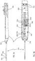
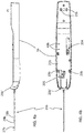
- FIGS 1a and 1b show different perspective views of a biopsy arrangement 1 according to one embodiment of the invention.
- the biopsy arrangement 1 is an arrangement for taking a biopsy in a human or animal tissue and comprises according to the invention a driver unit 3 and at least two different types of probes 5a, 5b, 5c, 5d which can be releasably connected to the driver unit 3.
- the driver unit 3 can suitably be hand held and it is reusable.
- the probes 5a, 5b, 5c, 5d are suitably single use biopsy probes or a marker probe.
- the at least two different types of probes comprise at least a first probe type 5a and a second probe type 5b. According to the invention these different types of probes are not only different dimensions of the biopsy needles but also including different functions for controlling the probe.
- At least one of the single use probe types which can be connected to and controlled by the driver unit comprises a suction transferring module and at least one of the single use probe types comprises a spring loaded needle manipulating module.
- both core needle biopsy and vacuum assisted biopsy can be provided by one and the same biopsy arrangement.
- the different types of probes use different sampling techniques.
- FIGs 2a and 2b show different perspective views of the driver unit 3 of the biopsy arrangement 1 as shown in Figures 1a and 1b .
- a driver connection surface 9 of the driver unit 3 can be seen which driver connection surface 9 can be mated and connected with a probe connection surface 21a, 21b, 21c, 21d of a connected probe 5a, 5b, 5c, 5d.
- Figures 3-6 show four different types of probes 5a, 5b, 5c, 5d according to embodiments of the invention which can be used together with the driver unit 3 as shown in Figures 2 .
- Figures 3a and 3b show a first probe type 5a
- Figures 4a and 4b show a second probe type 5b
- Figures 5a and 5b show a third probe type 5c
- Figures 6a and 6b show a fourth probe type 5d.
- at least two different single use probe types should be provided for connection to one and the same driver unit. All the four probe types 5a, 5b, 5c, 5d as shown in Figures 3 , 4 , 5 and 6 need not be provided according to the invention and furthermore different properties of the different probe types which will be described in detail below with reference to Figures 3-6 may be combined differently in different probe types and still be within the scope of the invention.
- the driver unit 3 comprises at least two different probe controlling devices 101, 102, 103, 104 which are controlling different probe modules 201, 202, 203, 204, 205, 206, 207, 208, 209 in a connected probe 5a, 5b, 5c, 5d.
- the at least two different probe controlling devices 101, 102, 103, 104 comprise at least a suction generating device 101 and a needle moving device 102.
- the needle moving device 102 is a DC motor both directly coupled to a cogwheel 102a generating rotational movement but also coupled to a linear screw 102b with an actuator generating a longitudinal movement.
- the driver unit 3 can be connected to a base unit (not shown).
- the base unit can provide power and possibly also vacuum and pressurized air to the driver unit 3.
- the driver unit 3 can be connected directly to a power point without the need of a base unit in between. Power is needed both for the suction generating device 101 and the needle moving device 102.
- the suction generating device 101 is typically a sealed air connection coupled to a vacuum pump with an integrated back flow valve to ensure air only flows in on direction.
- the driver unit 3 further comprises a pulsing device 103 which can transfer longitudinal, reciprocating pulses to a biopsy needle of a connected probe.
- a reciprocating oscillating movement of the needle or a part of the needle is especially suitable when dense or fibrotic tissue need to be penetrated on the way to a tumor.
- the oscillating movement can preferably be used in order to improve the filling of the needle with tissue utilizing the inertia stabilization caused by the fast acceleration pulses applied to the needle.
- the pulsing device 103 can be a piston arrangement.
- Such a piston arrangement comprises a piston arranged to reciprocate in a piston casing.
- This piston arrangement is driven by a movement generating source (not shown), e.g. weight accelerated by pressurized air generated by a compressor.
- a movement generating source can be provided either in the driver unit 3 or in a base unit to which the driver unit can be connected.
- the piston arrangement is driven by magnetic forces, hydraulic forces or spring-generated forces.
- the piston arrangement is driven by forces generated by an electric motor or a piezo-electric device.
- EP 2323563 , EP 3206587 and WO 2016/058845 the present applicant describes details of one type of pulsing device which can be used also in this invention.
- the driver unit 3 comprises furthermore a first connection device 11 for realeasable connection to said probes 5a, 5b, 5c, 5d.
- the first connection device 11 can be provided as one or more recesses and/or projecting parts 11 for mating with corresponding recesses/projecting parts 23a, 23b, 23c, 23d on a probe 5a, 5b, 5c, 5d.
- These recesses and/or projecting parts 11 can be provided to the driver connection surface 9 as shown in Figure 2b , i.e. in this example two projecting parts 11 in one end of the driver unit and two recesses in an opposite end.
- FIG. 2b i.e. in this example two projecting parts 11 in one end of the driver unit and two recesses in an opposite end.
- different configurations are of course possible.
- the first connection device 11 further comprises a front connection device 11a provided in a front end of the driver unit 3 for mating with a front connection device 23a' of a probe.
- the first connection device 11 furthermore comprises a releasing button 11b. A probe connected to the driver unit 3 can be released by pushing this releasing button 11b.
- This release button 11b is hereby connected to a locking device provided to the recesses and/or projecting parts 11 of the first connection device 11.
- At least one activation button 13a, 13b is provided on an outside surface of the driver unit 3.
- This activation button 13a, 13b is connected to the at least two different probe controlling devices 101, 102, 103, 104 of the driver unit 3.
- a physician using the biopsy arrangement 1 can activate the different probe controlling devices by pushing this at least one activation button 13a, 13b.
- One push on the activation button can in some embodiments initiate a whole sampling sequence and/or a number of pushes on the activation button can activate different steps in a sampling sequence. More than one activation button 13a, 13b could also be provided for initiating different steps of a sampling sequence.
- two activation buttons 13a, 13b are provided, where a first activation button 13a is for activation of a sampling sequence and/or different steps of a sampling sequence and a second activation button 13b is provided for controlling a pulsing device of the driver unit as described above.
- a first probe type 5a is shown in Figures 3a and 3b.
- Figure 3a is a side view of the first probe type 5a
- Figure 3b is a top view of the first probe type 5a showing a probe connection surface 21a of the first probe type 5a which probe connection surface 21a can be mated and connected with the driver connection surface 9 of the driver unit 3.
- the first probe type 5a comprises a second connection device 23a for releasable connection to the first connection device 11 of the driver unit 3.
- the second connection device 23a can be provided as one or more recesses and/or projecting parts for mating with corresponding recesses/projecting parts 11 on a driver unit 3.
- the recesses and/or projecting parts 23a can be provided to the probe connection surface 21a as shown in Figure 3b , i.e. in this example two projecting parts 23a in one end of the probe and two recesses 23a in an opposite end.
- the second connection device 23a further comprises a front connection device 23a' provided in a front end of the probe 5a for mating with a front connection device 11a of the driver unit 3.
- the first probe type 5a comprises at least two different probe modules 201, 202. These probe modules comprise a suction transferring module 201 and at least one needle manipulating module 202.
- the suction transferring module 201 is configured for transferring suction from the suction generating device 101 of the driver unit 3 to a needle 25a of the first probe 5a.
- a biopsy sample can be sucked into a sample receiving opening 27a of the needle and the biopsy sample can possibly also be transferred within the needle 25 to a sample collection device 28a possibly provided in the single use probe 5a.
- a sample collection device 28a is not necessary for the invention.
- the at least one needle manipulating module 202 for the first probe type 5a is called a first probe type needle manipulating module 202 and it can be configured for providing longitudinal and/or rotational movement to at least a part of the needle 25a of the first probe type 5a.
- both longitudinal and rotational movement is provided to the needle 25.
- the needle 25a comprises an inner needle part 29a and an outer needle part 31a (which in this embodiment both are cannulas), i.e.
- the first probe type needle manipulating module 202 can be configured to provide longitudinal movement to only the inner needle part 29a in relation to the outer needle part 31a hereby providing the opening and closing of the sample receiving opening 27a. Furthermore the first probe type needle manipulating module 202 can be configured for providing rotational movement to only the inner needle part 29a in order to cut off the biopsy sample. However, another alternative would be to provide the longitudinal movement and the rotational movement to only the outer needle part 31a for cutting off the biopsy sample.
- the first probe type needle manipulating module 202 comprises in this embodiment a rotational movement generating part 202a, for example a cogwheel, and a longitudinal movement generating part 202b, for example a linear screw with an actuator.
- the first probe type needle manipulating module 202 is configured for connecting to the needle moving device 102 of the driver unit 3.
- the first probe type 5a further comprises a pulse transferring module 203, which is configured for transferring reciprocating pulses provided from the pulsing device 103 of the driver unit 3 to the biopsy needle 25a of the first probe type 5a when connected to the driver unit 3.
- This first probe type pulse transferring module 203 can be configured for transferring the reciprocating pulses to only one of the inner or outer needle part 29a, 31a of the needle 25a or to both the inner and outer needle part 29a, 31a. In this first probe type 5a it can be advantageous to only transfer the reciprocating pulses to the outer needle part 31a of the needle 25a.
- the whole sampling sequence can in one embodiment be initiated by only one push on a first activation button 13a of the driver unit 3 when the needle has been placed in a position suitable for tissue sampling.
- the suction generating device 101 is first activated for generating a vacuum to the needle and then the needle moving device 102 is automatically activated such that the inner needle part 29a is rotated and translated longitudinally in relation to the outer needle part 31a, first back for filling the needle with sample and then forward for severing the sample whereby the sample is transported to the sample collection device 28a due to the pressure difference.
- a second activation button 13b can be pushed for activating the pulsing device 103 during needle positioning before the sampling process.
- a second probe type 5b is shown in Figures 4a and 4b.
- Figure 4a is a side view of the second probe type 5b
- Figure 4b is a top view of the second probe type 5b showing a probe connection surface 21b of the second probe type 5a which probe connection surface 21b should be mated and connected with the driver connection surface 9.
- the second probe type comprises a second connection device 23b for releasable connection to the first connection device 11 of the driver unit 3 for example provided as projecting parts and/or recesses 23b and a front connection device 23b' on the probe connection surface 21b in the same way as described above for the first probe type 5a.
- the second probe type 5b comprises at least one probe module which is a needle manipulating module 204, in this embodiment called a second probe type spring loaded needle manipulating module 204.
- Said second probe type spring loaded needle manipulating module 204 is configured for providing a spring loaded longitudinal movement to at least a part of a needle 25b of the second probe type 5b.
- this needle 25b can comprise an inner needle part 29b and an outer needle part 31b (which in this embodiment both can be cannulas) whereby a sample receiving opening 27b can be opened or closed by a relative motion between the inner and outer needle part 29b, 31b.
- the inner needle part 29a can in one embodiment be provided with the sample receiving opening 27b at a side surface of a top part of the needle and the outer needle part 31b can be configured for cutting the sample provided into the opening 27b when the outer needle part 31b is moved in relation to the inner needle part 29b for closing the opening 27b.
- the longitudinal motion of first the inner needle part 29b into a tumor and thereafter the outer needle part 31b to cut the sample is in this second probe type 5b provided by a spring loaded action. This is what usually is called core needle biopsy.
- the spring loading is provided in the second probe type spring loaded needle manipulating module 204 which is connected to the needle moving device 102 of the driver unit 3 for being activated. At least one spring is hereby provided in the second probe type spring loaded needle manipulating module 204.
- the second probe type spring loaded needle manipulating module 204 is configured for connecting to the needle moving device 102 of the driver unit 3 for loading and releasing the at least one spring.
- a coil spring can be used and loaded to for example 30-60N in dependence of the weight of the needle part to be accelerated.
- the outer needle part should be accelerated over a distance between 15-30mm to a speed of 7-15m/s.
- the second probe type 5b can in one embodiment of the invention comprise a pulse transferring module 205, which is configured for transferring reciprocating pulses provided from the pulsing device 103 of the driver unit 3 to the needle 25b of the second probe type 5b when connected to the driver unit 3.
- This second probe type pulse transferring module 205 can be configured for transferring the reciprocating pulses to only one of the inner or outer needle part 29b, 31b of the needle 25b or to both the inner and outer needle part 29b, 31b. In this second probe type 5b it can be advantageous to transfer the reciprocating pulses to both the inner and outer needle parts 29b, 31b of the needle 25b.
- the sampling sequence can in one embodiment be initiated by a first push on a first activation button 13a of the driver unit 3 when the needle has been placed in a position suitable for tissue sampling.
- the first push on the first activation button 13a will activate the needle moving device 102 such that an outer needle part 31b of the needle will be retracted, a spring will be loaded and tissue will fill the sample receiving opening 27b.
- a second push on the first activation button 13a will release the spring whereby the outer needle part 31b will move forward and hereby close the sample receiving opening 27b of the needle and a sample will be severed.
- a second activation button 13b can be pushed for activating the pulsing device 103 during needle positioning before the sampling process.
- a third probe type 5c is shown in Figures 5a and 5b.
- Figure 5a is a side view of the third probe type 5c
- Figure 5b is a top view of the third probe type 5c showing a probe connection surface 21c of the third probe type 5c which probe connection surface 21c should be mated and connected with the driver connection surface 9.
- the third probe type comprises a second connection device 23c for releasable connection to the first connection device 11 of the driver unit 3 for example provided as projecting parts and/or recesses 23c and a front connection device 23c' on the probe connection surface 21c in the same way as described above for the first probe type 5a.
- the third probe type 5c comprises at least two probe modules.
- the third probe type 5c is a different type of probe than the first and the second probe types.
- Probe modules of the third probe type 5c comprise a suction transferring module 206, a needle manipulating module 207, in this embodiment called a third probe type needle manipulating module 207 and possibly also a pulse transferring module 208.
- Said suction transferring module 206 is configured for transferring a suction from the suction generating device 101 of the driver unit 3 to a needle 25c of the third probe type 5c.
- Said third probe type needle manipulating module 207 is configured for providing longitudinal movement to an inner needle part 29c of the needle 25c of the third probe type 5c for positioning of the inner needle part 29c in a front or back position in relation to an outer needle part 31c of the needle 25c.
- Said pulse transferring module 208 is configured for transferring reciprocating pulses provided from the pulsing device 103 of the driver unit 3 to the inner and/or outer needle part 29c, 31c of the needle 25c of the third probe type 5c.
- a needle part connection device is provided in connection with the pulse transferring module 208, which needle part connection device is configured for keeping the inner and outer needle part together or separated such that the pulses can be provided either to the combined unit of inner and outer needle part of the needle or to one of them separately.
- a pulse transferring module and needle part connection device is described by the present applicant in EP 3206587 and WO 2016/058845 .
- the third probe type comprises furthermore in this embodiment, but not necessarily a sample separating module 209.
- the sample separating module 209 is configured to be connected to a sample separating device 104 (seen in Figure 2b ) optionally provided in the driver unit 3 when the third probe is connected to the driver unit.
- the sample separating module 209 and sample separating device 104 are however not necessary for the invention.
- the sample separating device 104, provided in the driver unit 3 can be a cogwheel connected to a motor and the sample separating module 209 provided in the probe can be a cogwheel connected to an outer needle part 31c of the needle 25c such that a rotational movement can be provided to the outer needle part 31c in order to separate a sample, i.e. cut a sample from the tissue.
- the sampling sequence can in one embodiment be initiated by a first push on a first activation button 13a of the driver unit 3 when the needle has been placed in a position suitable for tissue sampling.
- the first push will in one embodiment activate the needle moving device 102 such that the inner needle part 29c is retracted and also activate the suction generating device 101.
- the second activation button 13b can be used for activating the pulsing device 103.
- the needle can be pulsed into the lesion and sample will fill the needle.
- a second push of the first activation button 13a will activate the sample separation device 104 and a sample will be severed as described above.
- a third push of the first activation button 13a can then activate the needle moving device 102 again such that the inner needle part 29c is moved forward and the sample hereby is pushed out from the needle.
- the inner needle part can be a solid trocar and the outer needle part a cannula.
- a fourth probe type 5d is shown in Figures 6a and 6b.
- Figure 6a is a side view of the fourth probe type 5d
- Figure 6b is a top view of the fourth probe type 5d showing a probe connection surface 21d of the fourth probe type 5d which probe connection surface 21d should be mated and connected with the driver connection surface 9.
- the fourth probe type comprises a second connection device 23d for releasable connection to the first connection device 11 of the driver unit 3 for example provided as projecting parts and/or recesses 23d and a front connection device 23d' on the probe connection surface 21d in the same way as described above for the first probe type 5a.
- the fourth probe type 5d is similar to the second probe type 5b and comprises a needle manipulating module 204', which is spring loaded in the same way as described above in relation to the second probe type 5b.
- the fourth probe type 5d can suitably also comprise a pulse transferring module 205', which is configured for transferring reciprocating pulses provided from the pulsing device 103 of the driver unit 3 to a needle 25d of the fourth probe type 5d when connected to the driver unit 3.
- the needle 25d of the fourth probe type 5d comprises an inner needle part 29d and an outer needle part 31d, where the inner needle part 29d is arranged to push out a marker 32 in the tissue when the needle 25d has been positioned correctly in the tissue.
- the longitudinal movement of the inner needle part 29d for pushing out the marker 32 is controlled by the needle manipulating module 204'.
- the inner needle part can be a solid trocar and the outer needle part can be a cannula.
- the outer needle part 31d is suitably provided with a sharp beveled end for penetrating the tissue.
- any one of the first, second or third probe types 5a, 5b, 5c can comprise a further probe module (not shown) for leaving a marker in a human or animal tissue, i.e. a marker function could be integrated in the first, second and/or third probe types 5a, 5b, 5c.
- the needles 25a, 25b, 25c, 25d of the different probe types 5a, 5b, 5c, 5d can as described above comprise an inner and an outer needle part 29a, b, c, d, 31a, b, c, d.
- the sampling method can be either a distal-tip sampling method as shown for the third probe type 5c or a side aperture sampling method as shown for the first and second probe types 5a, 5b.
- Each one of the different single use probe types 5a, 5b, 5c, 5d comprises according to one embodiment of the invention a unique probe identification 41a, 41b, 41c, 41d and the reusable drive unit 3 comprises a probe identification recognition device 43.
- the probe identification and the probe identification recognition device can be based on for example mechanical activation or electrical or optical reading.
- the probe identification is provided as projections provided in different patterns 41a, 41b, 41c, 41d on the connection surface 21a, 21b, 21c, 21d of the probes 5a, 5b, 5c, 5d. These projections are received in corresponding recesses with sensors 43 (probe identification recognition device) in the connection surface 9 of the driver unit 3.
- the probe identification recognition device 43 of the driver unit 3 is connected to the at least two different probe controlling devices 101, 102, 103, 104 and comprises control logic such that the probe identification recognition device 43 can activate certain probe controlling devices 101, 102, 103, 104 in dependence of which type of probe 5a, 5b, 5c, 5d has been identified by the probe identification recognition device 43.
- the control logic can be a microprocessor with software connected to position indicators.
- Probe modules can be chosen from the ones described above and be combined in different ways and further probe modules can be provided. Furthermore a design of the needle of the probe can be varied, for example either a distal-tip or a side aperture sampling method can be provided.
Claims (21)
- Agencement de biopsie (1) pour prélever une biopsie dans un tissu humain ou animal, ledit agencement de biopsie comprenant :- une unité d'entraînement (3) ; et- au moins deux différents types de sondes (5a, 5b, 5c, 5d) qui peuvent être connectées de manière amovible à l'unité d'entraînement (3), lesdits au moins deux différents types de sondes comprenant au moins un premier type de sonde (5a) et un deuxième type de sonde (5b),dans lequel ladite unité d'entraînement (3) comprend au moins deux dispositifs de commande de sonde différents (101, 102, 103, 104) qui commandent des modules de sonde différents (201, 202, 203, 204, 205, 206, 207, 208, 209) dans une sonde connectée (5a, 5b, 5c, 5d), lesdits au moins deux dispositifs de commande de sonde différents (101, 102, 103, 104) comprenant un dispositif de génération d'aspiration (101) et un dispositif de déplacement d'aiguille (102), et
dans lequel les modules de sonde (201, 202) du premier type de sonde (5a) comprennent un module de transfert d'aspiration (201) et au moins un module de manipulation d'aiguille (202), dans lequel ledit module de transfert d'aspiration (201) est conçu pour transférer une aspiration du dispositif de génération d'aspiration (101) de l'unité d'entraînement (3) à une aiguille (25a) du premier type de sonde (5a), et dans lequel ledit au moins un module de manipulation d'aiguille (202) est un module de manipulation d'aiguille (202) du premier type de sonde conçu pour imprimer un mouvement longitudinal et/ou de rotation à au moins une partie de l'aiguille (25a) du premier type de sonde (5a), et
dans lequel les modules de sonde (204) du deuxième type de sonde (5b) comprennent au moins un module de manipulation d'aiguille (204), qui est un module de manipulation d'aiguille (204) à ressort du deuxième type de sonde qui est conçu pour imprimer un mouvement longitudinal à ressort à au moins une partie d'une aiguille (25b) du deuxième type de sonde (5b),
dans lequel les différents types de sondes (5a, 5b, 5c, 5d) utilisent des techniques d'échantillonnage différentes, la biopsie au trocart et la biopsie assistée par le vide pouvant toutes deux être fournies par un seul et même agencement de biopsie, et dans lequel une unité d'entraînement peut être utilisée pour un certain nombre de différents types de sondes. - Agencement de biopsie (1) selon la revendication 1, dans lequel ledit dispositif de génération d'aspiration (101) de l'unité d'entraînement (3) est conçu pour se connecter à un module de transfert d'aspiration (201, 206) d'une sonde connectée (5a, 5b, 5c, 5d) et ledit dispositif de déplacement d'aiguille (102) de l'unité d'entraînement (3) est conçu pour se connecter à un ou plusieurs modules de manipulation d'aiguille (202, 204, 207) d'une sonde connectée (5a, 5b, 5c, 5d) pour commander le mouvement longitudinal et/ou de rotation d'au moins une partie d'une aiguille (25a, 25b, 25c, 25d) d'une sonde (5a, 5b, 5c, 5d) connectée à l'unité d'entraînement (3).
- Agencement de biopsie selon l'une quelconque des revendications précédentes, dans lequel lesdits dispositifs de commande de sonde (101, 102, 103, 104) de l'unité d'entraînement (3) comprennent en outre un dispositif à impulsions (103) qui peut transférer des impulsions de va-et-vient à une aiguille (25a, 25b, 25c, 25d) d'une sonde connectée (5a, 5b, 5c, 5d).
- Agencement de biopsie selon la revendication 3, dans lequel un autre module de sonde (203, 205) à la fois du premier type de sonde et du deuxième type de sonde (5a, 5b) est un module de transfert d'impulsions (203, 205) qui est conçu pour transférer des impulsions de va-et-vient fournies par le dispositif à impulsions (103) de l'unité d'entraînement (3) à au moins une partie d'une aiguille (25a, 25b) des premier et deuxième types de sonde (5a, 5b) lorsqu'elles sont connectées à l'unité d'entraînement (3).
- Agencement de biopsie selon la revendication 4, dans lequel le module de transfert d'impulsions (205, 208) d'au moins l'un des différents types de sondes (5b) est conçu pour transférer des impulsions de va-et-vient fournies par le dispositif à impulsions (103) de l'unité d'entraînement (3) à la fois à une partie d'aiguille intérieure et à une partie d'aiguille extérieure (29b,c, 31b,c) d'une aiguille (25b) de la sonde (5b) et dans lequel le module de transfert d'impulsions (203) d'un autre des différents types de sondes (5a) est conçu pour transférer des impulsions de va-et-vient fournies par le dispositif à impulsions (103) de l'unité d'entraînement (3) à une seule parmi une partie d'aiguille intérieure et une partie d'aiguille extérieure (29a, 31a) de l'aiguille (25a).
- Agencement de biopsie selon l'une quelconque des revendications précédentes, ledit agencement de biopsie (1) comprenant un troisième type de sonde (5c) qui peut être connecté de manière amovible à l'unité d'entraînement (3), ledit troisième type de sonde étant un type de sonde différent des premier et deuxième types de sonde (5a, 5b), dans lequel les modules de sonde (206, 207, 208, 209) du troisième type de sonde (5c) comprennent un module de transfert d'aspiration (206) et un module de manipulation d'aiguille (207), dans lequel ledit module de transfert d'aspiration (206) est conçu pour transférer une aspiration du dispositif de génération d'aspiration (101) de l'unité d'entraînement (3) à une aiguille (25c) du troisième type de sonde (5c) et dans lequel ledit module de manipulation d'aiguille (207) est un module de manipulation d'aiguille (207) du troisième type de sonde, qui est conçu pour imprimer un mouvement longitudinal à une partie d'aiguille intérieure (29c) de l'aiguille (25c) du troisième type de sonde (5c) pour le positionnement de la partie d'aiguille intérieure (29c) dans une position avant ou arrière par rapport à une partie d'aiguille extérieure (31c) de l'aiguille (25c) et conçu pour imprimer un mouvement de rotation à la partie d'aiguille extérieure (31c) de l'aiguille (25c).
- Agencement de biopsie selon la revendication 6, dans lequel ledit troisième type de sonde (5c) comprend en outre un module de séparation d'échantillon (209) conçu pour coopérer avec un dispositif de séparation d'échantillon (104) prévu dans l'unité d'entraînement (3), ledit dispositif de séparation d'échantillon (104) comprenant un moteur ou étant connecté à un moteur, dans lequel ledit module de séparation d'échantillon (209) est connecté à une partie d'aiguille extérieure (31c) de l'aiguille (25c) de sorte qu'un mouvement de rotation peut être imprimé à la partie d'aiguille extérieure (31c) à partir du dispositif de séparation d'échantillon (104) par l'intermédiaire du module de séparation d'échantillon (209).
- Agencement de biopsie selon la revendication 6 ou 7, dans lequel ledit troisième type de sonde (5c) comprend en outre un module de transfert d'impulsions (208) qui est conçu pour transférer des impulsions de va-et-vient fournies par le dispositif à impulsions (103) de l'unité d'entraînement (3) à une partie d'aiguille intérieure et/ou extérieure (29c, 31c) d'une aiguille (25c) du troisième type de sonde (5c).
- Agencement de biopsie selon l'une quelconque des revendications précédentes, ledit agencement de biopsie (1) comprenant en outre un quatrième type de sonde (5d) qui peut être connecté de manière amovible à l'unité d'entraînement (3), dans lequel ledit quatrième type de sonde est une sonde de marqueur (5d) conçue pour laisser un marqueur dans un tissu humain ou animal, laquelle sonde de marqueur (5d) pouvant être commandée par un ou plusieurs des dispositifs de commande de sonde (101, 102, 103, 104) prévus dans l'unité d'entraînement (3) .
- Agencement de biopsie selon l'une quelconque des revendications précédentes, dans lequel au moins l'un des au moins deux différents types de sondes (5c) comprend une aiguille à extrémité distale (25c) et au moins l'un des au moins deux différents types de sondes (5a, 5b) comprend une aiguille à ouverture latérale (25a, 25b).
- Agencement de biopsie selon l'une quelconque des revendications précédentes, dans lequel chacun des au moins deux différents types de sondes (5a, 5b, 5c, 5d) comprend une identification de sonde unique (41a, 41b, 41c, 41d) et l'unité d'entraînement (3) comprend un dispositif de reconnaissance d'identification de sonde (43) qui est connecté aux au moins deux dispositifs de commande de sonde différents (101, 102, 103, 104) et comprend une logique de commande de sorte que le dispositif de reconnaissance d'identification de sonde (43) peut activer certains dispositifs de commande de sonde (101, 102, 103, 104) en fonction du type de sonde (5a, 5b, 5c, 5d) qui a été identifié par le dispositif de reconnaissance d'identification de sonde (43).
- Agencement de biopsie selon l'une quelconque des revendications précédentes, dans lequel le premier type de sonde (5a) comprend un dispositif de collecte d'échantillons (29a) connecté à l'aiguille (25a).
- Unité d'entraînement (3) destiné à être utilisé conjointement avec au moins deux différents types de sondes (5a, 5b, 5c, 5d) pour prélever une biopsie dans un tissu humain ou animal, ladite unité d'entraînement (3) comprenant un premier dispositif de connexion (11) pour connecter de manière amovible lesdites sondes (5a, 5b, 5c, 5d), ladite unité d'entraînement (3) comprenant au moins deux dispositifs de commande de sonde différents (101, 102, 103, 104) qui peuvent commander des modules de sonde différents (201, 202, 203, 204, 205, 206, 207, 208, 209) dans une sonde connectée (5a, 5b, 5c, 5d), dans laquelle les différents types de sondes (5a, 5b, 5c, 5d) utilisent des techniques d'échantillonnage différentes, la biopsie au trocart et la biopsie assistée par le vide pouvant toutes deux être fournies par un seul et même agencement de biopsie, et dans laquelle une unité d'entraînement peut être utilisée pour un certain nombre de différents types de sondes.
- Unité d'entraînement selon la revendication 13, dans laquelle lesdits au moins deux dispositifs de commande de sonde différents (101, 102, 103, 104) de l'unité d'entraînement (3) comprennent un dispositif de génération d'aspiration (101) et au moins un dispositif de déplacement d'aiguille (102) pour commander le mouvement longitudinal et/ou de rotation d'une aiguille (25a, 25b, 25c, 25d) d'une sonde connectée (5a, 5b, 5c, 5d) .
- Unité d'entraînement selon l'une quelconque des revendications 13 et 14, dans laquelle lesdits dispositifs de commande de sonde (101, 102, 103, 104) de l'unité d'entraînement (3) comprennent un dispositif à impulsions (103) qui peut transférer des impulsions de va-et-vient à une aiguille (25a, 25b, 25c, 25d) d'une sonde connectée (5a, 5b, 5c, 5d).
- Unité d'entraînement selon l'une quelconque des revendications 13 à 15, comprenant en outre un dispositif de reconnaissance d'identification de sonde (43) conçu pour reconnaître une identification de sonde (41a, 41b, 41c, 41d) d'une sonde connectée (5a, 5b, 5c, 5d), lequel dispositif de reconnaissance d'identification de sonde (43) étant connecté aux au moins deux dispositifs de commande de sonde différents (101, 102, 103, 104) et comprenant une logique de commande de sorte que le dispositif de reconnaissance d'identification de sonde (43) peut activer certains dispositifs de commande de sonde (101, 102, 103, 104) en fonction du type de sonde (5a, 5b, 5c, 5d) qui a été identifié par le dispositif de reconnaissance d'identification de sonde (43).
- Agencement d'au moins deux différents types de sondes (5a, 5b, 5c, 5d) pour prélever une biopsie ou laisser un marqueur dans un tissu humain ou animal, lesquelles sondes (5a, 5b, 5c, 5d) comprenant chacune un second dispositif de connexion (23a, 23b, 23c, 23d) conçu pour se connecter de manière amovible à un premier dispositif de connexion (11) d'une unité d'entraînement (3) selon l'une quelconque des revendications 13 à 16, dans lequel lesdits au moins deux différents types de sondes (5a, 5b, 5c, 5d) comprennent au moins un premier type de sonde (5a) et un deuxième type de sonde (5b), dans lequel lesdits au moins deux types de sondes (5a, 5b, 5c, 5d) comprennent des modules de sonde différents (201, 202, 203, 204, 205, 206, 207, 208, 209) qui sont commandés par les au moins deux dispositifs de commande de sonde différents (101, 102, 103, 104) compris dans l'unité d'entraînement (3) lorsqu'elles sont connectées à une unité d'entraînement (3) selon l'une quelconque des revendications 13 à 16, dans lequel les modules de sonde (201, 202) du premier type de sonde (5a) comprennent un module de transfert d'aspiration (201) et au moins un module de manipulation d'aiguille (202), dans lequel ledit module de transfert d'aspiration (201) est conçu pour transférer une aspiration du dispositif de génération d'aspiration (101) de l'unité d'entraînement (3) à une aiguille (25a) du premier type de sonde (5a), et dans lequel ledit au moins un module de manipulation d'aiguille (202) est un module de manipulation d'aiguille (202) du premier type de sonde conçu pour imprimer un mouvement longitudinal et/ou de rotation à au moins une partie de l'aiguille (25a) du premier type de sonde (5a), et
dans lequel les modules de sonde (204) du deuxième type de sonde (5b) comprennent au moins un module de manipulation d'aiguille (204), qui est un module de manipulation d'aiguille (204) à ressort du deuxième type de sonde qui est conçu pour imprimer un mouvement longitudinal à ressort à au moins une partie d'une aiguille (25b) du deuxième type de sonde (5b),
dans lequel les différents types de sondes (5a, 5b, 5c, 5d) utilisent des techniques d'échantillonnage différentes, la biopsie au trocart et la biopsie assistée par le vide pouvant toutes deux être fournies par un seul et même agencement de biopsie, et dans lequel une unité d'entraînement peut être utilisée pour un certain nombre de différents types de sondes. - Agencement d'au moins deux différents types de sondes selon la revendication 17, dans lequel chaque sonde comprend en outre un module de transfert d'impulsions (203, 205, 208, 205') conçu pour transférer des impulsions de va-et-vient fournies par un dispositif à impulsions (103) de l'unité d'entraînement (3) à au moins une partie d'une aiguille (25a, 25b, 25c, 25d) de la sonde (5a, 5b, 5c, 5d) .
- Agencement d'au moins deux différents types de sondes selon la revendication 17 ou 18, comprenant en outre un troisième type de sonde (5c) qui peut être connecté de manière amovible à l'unité d'entraînement selon l'une quelconque des revendications 13 à 16, ledit troisième type de sonde (5c) étant un type de sonde différent des premier et deuxième types de sonde (5a, 5b), dans lequel les modules de sonde (206, 207, 208, 209) du troisième type de sonde (5c) comprennent un module de transfert d'aspiration (206) et un module de manipulation d'aiguille (207), dans lequel ledit module de manipulation d'aiguille (207) est un module de manipulation d'aiguille (207) du troisième type de sonde, qui est conçu pour imprimer un mouvement longitudinal à une partie d'aiguille intérieure (29c) d'une aiguille (25c) du troisième type de sonde (5c) pour le positionnement de la partie d'aiguille intérieure (29c) dans une position avant ou arrière par rapport à une partie d'aiguille extérieure (31c) de l'aiguille (25c) et conçu pour imprimer un mouvement de rotation à la partie d'aiguille extérieure (31c) de l'aiguille (25c) et dans lequel ledit module de transfert d'aspiration (206) est conçu pour transférer une aspiration du dispositif de génération d'aspiration (101) de l'unité d'entraînement (3) à l'aiguille (25c) du troisième type de sonde (5c).
- Agencement d'au moins deux différents types de sondes selon la revendication 19, dans lequel le troisième type de sonde (5c) comprend en outre un module de séparation d'échantillon (209) conçu pour coopérer avec un dispositif de séparation d'échantillon (104) prévu dans l'unité d'entraînement (3), ledit dispositif de séparation d'échantillon (104) comprenant un moteur ou étant connecté à un moteur, dans lequel ledit module de séparation d'échantillon (209) est connecté à une partie d'aiguille extérieure (31c) de l'aiguille (25c) de sorte qu'un mouvement de rotation peut être imprimé à la partie d'aiguille extérieure (31c) à partir du dispositif de séparation d'échantillon (104) par l'intermédiaire du module de séparation d'échantillon (209).
- Agencement d'au moins deux différents types de sondes selon l'une quelconque des revendications 17 à 20, dans lequel chaque sonde comprend en outre une identification de sonde unique (41a, 41b, 41c, 41d) par laquelle le type de sonde (5a, 5b, 5c, 5d) peut être reconnu par un dispositif de reconnaissance d'identification de sonde (43) de l'unité d'entraînement (3) lorsque ladite sonde (5a, 5b, 5c, 5d) est connectée à l'unité d'entraînement (3).
Priority Applications (4)
| Application Number | Priority Date | Filing Date | Title |
|---|---|---|---|
| EP18192314.5A EP3616625B1 (fr) | 2018-09-03 | 2018-09-03 | Agencement de biopsie |
| US17/272,983 US20220211358A1 (en) | 2018-09-03 | 2019-08-30 | A biopsy arrangement |
| PCT/EP2019/073208 WO2020048888A1 (fr) | 2018-09-03 | 2019-08-30 | Agencement d'aiguille de biopsie |
| CN201980057490.XA CN112770678A (zh) | 2018-09-03 | 2019-08-30 | 活检布置 |
Applications Claiming Priority (1)
| Application Number | Priority Date | Filing Date | Title |
|---|---|---|---|
| EP18192314.5A EP3616625B1 (fr) | 2018-09-03 | 2018-09-03 | Agencement de biopsie |
Publications (2)
| Publication Number | Publication Date |
|---|---|
| EP3616625A1 EP3616625A1 (fr) | 2020-03-04 |
| EP3616625B1 true EP3616625B1 (fr) | 2021-03-24 |
Family
ID=63490359
Family Applications (1)
| Application Number | Title | Priority Date | Filing Date |
|---|---|---|---|
| EP18192314.5A Active EP3616625B1 (fr) | 2018-09-03 | 2018-09-03 | Agencement de biopsie |
Country Status (4)
| Country | Link |
|---|---|
| US (1) | US20220211358A1 (fr) |
| EP (1) | EP3616625B1 (fr) |
| CN (1) | CN112770678A (fr) |
| WO (1) | WO2020048888A1 (fr) |
Families Citing this family (2)
| Publication number | Priority date | Publication date | Assignee | Title |
|---|---|---|---|---|
| CN113243941B (zh) * | 2021-04-30 | 2023-06-27 | 重庆西山科技股份有限公司 | 模式可调的活检系统 |
| CN116784893B (zh) * | 2023-05-28 | 2024-01-19 | 湖南迅卓实业有限公司 | 一种用于活检的旋转组织样本切割器 |
Family Cites Families (31)
| Publication number | Priority date | Publication date | Assignee | Title |
|---|---|---|---|---|
| US5172701A (en) | 1990-02-28 | 1992-12-22 | Medical Device Technologies, Inc. | Single use automated soft tissue aspiration biopsy device |
| US5121751A (en) | 1990-03-16 | 1992-06-16 | Ryder International Corporation | Instrument for tissue sampling |
| US5188118A (en) | 1990-11-07 | 1993-02-23 | Terwilliger Richard A | Automatic biopsy instrument with independently actuated stylet and cannula |
| US5392790A (en) | 1993-04-30 | 1995-02-28 | Ryder International Corporation | Instrument for obtaining bore type tissue sampling |
| US5615690A (en) | 1995-02-15 | 1997-04-01 | Symbiosis Corporation | Tissue core biopsy cannula |
| IT1292837B1 (it) | 1997-04-03 | 1999-02-11 | Alberto Bauer | Apparecchio chirurgico per biopsia. |
| US6063037A (en) | 1998-08-21 | 2000-05-16 | Manan Medical Products, Inc. | Bone marrow biopsy needle |
| US8282573B2 (en) | 2003-02-24 | 2012-10-09 | Senorx, Inc. | Biopsy device with selectable tissue receiving aperture orientation and site illumination |
| AU3306500A (en) | 1999-03-19 | 2000-10-09 | Paul Cervi | Biopsy needle |
| RU2212848C2 (ru) | 2001-01-30 | 2003-09-27 | Шахматов Дмитрий Тихонович | Вакуумно-механическая игла для пункционной биопсии |
| DE20211934U1 (de) | 2002-08-02 | 2002-09-19 | Heske Norbert F | Biopsievorrichtung zur Entnahme von Gewebeproben unter Vakuum |
| BRPI0407847A (pt) | 2003-02-25 | 2006-02-14 | Ethicon Endo Surgery Inc | dispositivo de biópsia com avanço de cortador de velocidade variável |
| US9408592B2 (en) * | 2003-12-23 | 2016-08-09 | Senorx, Inc. | Biopsy device with aperture orientation and improved tip |
| US8568334B2 (en) | 2004-05-11 | 2013-10-29 | Inrad, Inc. | Core biopsy device |
| US7867173B2 (en) * | 2005-08-05 | 2011-01-11 | Devicor Medical Products, Inc. | Biopsy device with replaceable probe and incorporating vibration insertion assist and static vacuum source sample stacking retrieval |
| US7828748B2 (en) | 2005-08-05 | 2010-11-09 | Devicor Medical Products, Inc. | Vacuum syringe assisted biopsy device |
| US7806834B2 (en) | 2006-03-07 | 2010-10-05 | Devicor Medical Products, Inc. | Device for minimally invasive internal tissue removal |
| US7938786B2 (en) * | 2006-12-13 | 2011-05-10 | Devicor Medical Products, Inc. | Vacuum timing algorithm for biopsy device |
| US20120283563A1 (en) * | 2011-05-03 | 2012-11-08 | Moore Kyle P | Biopsy device with manifold alignment feature and tissue sensor |
| US8480595B2 (en) * | 2006-12-13 | 2013-07-09 | Devicor Medical Products, Inc. | Biopsy device with motorized needle cocking |
| CA2672664C (fr) * | 2006-12-13 | 2017-09-05 | Ethicon Endo-Surgery, Inc. | Dispositif de biopsie, systeme et methode |
| US8066717B2 (en) | 2007-03-19 | 2011-11-29 | Restoration Robotics, Inc. | Device and method for harvesting and implanting follicular units |
| EP2138104A1 (fr) | 2008-06-25 | 2009-12-30 | Vibra Tech AB | Agencement de biopsie du cýur |
| US10080578B2 (en) | 2008-12-16 | 2018-09-25 | Nico Corporation | Tissue removal device with adjustable delivery sleeve for neurosurgical and spinal surgery applications |
| US8628482B2 (en) * | 2010-02-24 | 2014-01-14 | Devicor Medical Products, Inc. | Needle tip for biopsy device |
| JP5890411B2 (ja) | 2010-07-27 | 2016-03-22 | プロメックス・テクノロジーズ・エルエルシー | 完全コア生検装置 |
| EP2520237A4 (fr) | 2010-07-30 | 2017-08-30 | Olympus Corporation | Aiguille médicale et instrument médical |
| US9955955B2 (en) * | 2011-12-05 | 2018-05-01 | Devicor Medical Products, Inc. | Biopsy device with slide-in probe |
| JP6183858B2 (ja) | 2012-07-06 | 2017-08-23 | 国立大学法人鳥取大学 | 生検針 |
| EP3009076A1 (fr) | 2014-10-13 | 2016-04-20 | NeoDynamics AB | Agencement de trocart pour dispositif d'échantillonnage de tissu |
| EP3009075A1 (fr) | 2014-10-13 | 2016-04-20 | NeoDynamics AB | Dispositif d'échantillonnage de tissu avec pointe distale |
-
2018
- 2018-09-03 EP EP18192314.5A patent/EP3616625B1/fr active Active
-
2019
- 2019-08-30 WO PCT/EP2019/073208 patent/WO2020048888A1/fr active Application Filing
- 2019-08-30 US US17/272,983 patent/US20220211358A1/en active Pending
- 2019-08-30 CN CN201980057490.XA patent/CN112770678A/zh active Pending
Non-Patent Citations (1)
| Title |
|---|
| None * |
Also Published As
| Publication number | Publication date |
|---|---|
| WO2020048888A1 (fr) | 2020-03-12 |
| US20220211358A1 (en) | 2022-07-07 |
| CN112770678A (zh) | 2021-05-07 |
| EP3616625A1 (fr) | 2020-03-04 |
Similar Documents
| Publication | Publication Date | Title |
|---|---|---|
| US9439632B2 (en) | Self-contained handheld biopsy needle | |
| US9155527B2 (en) | Soft tissue coring biopsy devices and methods | |
| EP1520518B1 (fr) | Outil de biopsie avec mécanisme interne de prélèvement d'échantillons | |
| US10231750B2 (en) | Excisional device distal working end actuation mechanism and method | |
| JP2005288175A (ja) | 外科生検装置を用いてマーカーを配置するためのマーカー装置及び方法 | |
| US11083441B2 (en) | Distal tip tissue sampling arrangement | |
| US10342519B2 (en) | Trocar arrangement for tissue sampling device | |
| EP3616625B1 (fr) | Agencement de biopsie | |
| WO2002062231A2 (fr) | Appareil et procede de biopsie | |
| CN212281441U (zh) | 活检针 | |
| JP2021532872A (ja) | 単一挿入で複数のサンプルを収集するためのコア針生検デバイス | |
| US20220338850A1 (en) | A biopsy arrangement | |
| EP3292822A2 (fr) | Dispositif de biopsie |
Legal Events
| Date | Code | Title | Description |
|---|---|---|---|
| PUAI | Public reference made under article 153(3) epc to a published international application that has entered the european phase |
Free format text: ORIGINAL CODE: 0009012 |
|
| STAA | Information on the status of an ep patent application or granted ep patent |
Free format text: STATUS: THE APPLICATION HAS BEEN PUBLISHED |
|
| AK | Designated contracting states |
Kind code of ref document: A1 Designated state(s): AL AT BE BG CH CY CZ DE DK EE ES FI FR GB GR HR HU IE IS IT LI LT LU LV MC MK MT NL NO PL PT RO RS SE SI SK SM TR |
|
| AX | Request for extension of the european patent |
Extension state: BA ME |
|
| STAA | Information on the status of an ep patent application or granted ep patent |
Free format text: STATUS: REQUEST FOR EXAMINATION WAS MADE |
|
| 17P | Request for examination filed |
Effective date: 20200825 |
|
| RBV | Designated contracting states (corrected) |
Designated state(s): AL AT BE BG CH CY CZ DE DK EE ES FI FR GB GR HR HU IE IS IT LI LT LU LV MC MK MT NL NO PL PT RO RS SE SI SK SM TR |
|
| GRAP | Despatch of communication of intention to grant a patent |
Free format text: ORIGINAL CODE: EPIDOSNIGR1 |
|
| STAA | Information on the status of an ep patent application or granted ep patent |
Free format text: STATUS: GRANT OF PATENT IS INTENDED |
|
| INTG | Intention to grant announced |
Effective date: 20201208 |
|
| RIN1 | Information on inventor provided before grant (corrected) |
Inventor name: SCHAESSBURGER, KAI-UWE Inventor name: FOGHELIN, ANNA Inventor name: SVANBERG, LARS-PETER Inventor name: VRENNING, JOERGEN Inventor name: STAHLE, RONNY Inventor name: ERIKSRUD, ANNA Inventor name: OLSEN, MAGNUS |
|
| GRAS | Grant fee paid |
Free format text: ORIGINAL CODE: EPIDOSNIGR3 |
|
| GRAA | (expected) grant |
Free format text: ORIGINAL CODE: 0009210 |
|
| STAA | Information on the status of an ep patent application or granted ep patent |
Free format text: STATUS: THE PATENT HAS BEEN GRANTED |
|
| AK | Designated contracting states |
Kind code of ref document: B1 Designated state(s): AL AT BE BG CH CY CZ DE DK EE ES FI FR GB GR HR HU IE IS IT LI LT LU LV MC MK MT NL NO PL PT RO RS SE SI SK SM TR |
|
| REG | Reference to a national code |
Ref country code: GB Ref legal event code: FG4D |
|
| REG | Reference to a national code |
Ref country code: CH Ref legal event code: EP |
|
| REG | Reference to a national code |
Ref country code: IE Ref legal event code: FG4D |
|
| REG | Reference to a national code |
Ref country code: AT Ref legal event code: REF Ref document number: 1373659 Country of ref document: AT Kind code of ref document: T Effective date: 20210415 Ref country code: DE Ref legal event code: R096 Ref document number: 602018014289 Country of ref document: DE |
|
| REG | Reference to a national code |
Ref country code: LT Ref legal event code: MG9D |
|
| PG25 | Lapsed in a contracting state [announced via postgrant information from national office to epo] |
Ref country code: FI Free format text: LAPSE BECAUSE OF FAILURE TO SUBMIT A TRANSLATION OF THE DESCRIPTION OR TO PAY THE FEE WITHIN THE PRESCRIBED TIME-LIMIT Effective date: 20210324 Ref country code: GR Free format text: LAPSE BECAUSE OF FAILURE TO SUBMIT A TRANSLATION OF THE DESCRIPTION OR TO PAY THE FEE WITHIN THE PRESCRIBED TIME-LIMIT Effective date: 20210625 Ref country code: HR Free format text: LAPSE BECAUSE OF FAILURE TO SUBMIT A TRANSLATION OF THE DESCRIPTION OR TO PAY THE FEE WITHIN THE PRESCRIBED TIME-LIMIT Effective date: 20210324 Ref country code: BG Free format text: LAPSE BECAUSE OF FAILURE TO SUBMIT A TRANSLATION OF THE DESCRIPTION OR TO PAY THE FEE WITHIN THE PRESCRIBED TIME-LIMIT Effective date: 20210624 Ref country code: NO Free format text: LAPSE BECAUSE OF FAILURE TO SUBMIT A TRANSLATION OF THE DESCRIPTION OR TO PAY THE FEE WITHIN THE PRESCRIBED TIME-LIMIT Effective date: 20210624 |
|
| PG25 | Lapsed in a contracting state [announced via postgrant information from national office to epo] |
Ref country code: SE Free format text: LAPSE BECAUSE OF FAILURE TO SUBMIT A TRANSLATION OF THE DESCRIPTION OR TO PAY THE FEE WITHIN THE PRESCRIBED TIME-LIMIT Effective date: 20210324 Ref country code: LV Free format text: LAPSE BECAUSE OF FAILURE TO SUBMIT A TRANSLATION OF THE DESCRIPTION OR TO PAY THE FEE WITHIN THE PRESCRIBED TIME-LIMIT Effective date: 20210324 Ref country code: RS Free format text: LAPSE BECAUSE OF FAILURE TO SUBMIT A TRANSLATION OF THE DESCRIPTION OR TO PAY THE FEE WITHIN THE PRESCRIBED TIME-LIMIT Effective date: 20210324 |
|
| REG | Reference to a national code |
Ref country code: NL Ref legal event code: MP Effective date: 20210324 |
|
| REG | Reference to a national code |
Ref country code: AT Ref legal event code: MK05 Ref document number: 1373659 Country of ref document: AT Kind code of ref document: T Effective date: 20210324 |
|
| PG25 | Lapsed in a contracting state [announced via postgrant information from national office to epo] |
Ref country code: NL Free format text: LAPSE BECAUSE OF FAILURE TO SUBMIT A TRANSLATION OF THE DESCRIPTION OR TO PAY THE FEE WITHIN THE PRESCRIBED TIME-LIMIT Effective date: 20210324 |
|
| PG25 | Lapsed in a contracting state [announced via postgrant information from national office to epo] |
Ref country code: CZ Free format text: LAPSE BECAUSE OF FAILURE TO SUBMIT A TRANSLATION OF THE DESCRIPTION OR TO PAY THE FEE WITHIN THE PRESCRIBED TIME-LIMIT Effective date: 20210324 Ref country code: EE Free format text: LAPSE BECAUSE OF FAILURE TO SUBMIT A TRANSLATION OF THE DESCRIPTION OR TO PAY THE FEE WITHIN THE PRESCRIBED TIME-LIMIT Effective date: 20210324 Ref country code: LT Free format text: LAPSE BECAUSE OF FAILURE TO SUBMIT A TRANSLATION OF THE DESCRIPTION OR TO PAY THE FEE WITHIN THE PRESCRIBED TIME-LIMIT Effective date: 20210324 Ref country code: SM Free format text: LAPSE BECAUSE OF FAILURE TO SUBMIT A TRANSLATION OF THE DESCRIPTION OR TO PAY THE FEE WITHIN THE PRESCRIBED TIME-LIMIT Effective date: 20210324 Ref country code: AT Free format text: LAPSE BECAUSE OF FAILURE TO SUBMIT A TRANSLATION OF THE DESCRIPTION OR TO PAY THE FEE WITHIN THE PRESCRIBED TIME-LIMIT Effective date: 20210324 |
|
| PG25 | Lapsed in a contracting state [announced via postgrant information from national office to epo] |
Ref country code: IS Free format text: LAPSE BECAUSE OF FAILURE TO SUBMIT A TRANSLATION OF THE DESCRIPTION OR TO PAY THE FEE WITHIN THE PRESCRIBED TIME-LIMIT Effective date: 20210724 Ref country code: PT Free format text: LAPSE BECAUSE OF FAILURE TO SUBMIT A TRANSLATION OF THE DESCRIPTION OR TO PAY THE FEE WITHIN THE PRESCRIBED TIME-LIMIT Effective date: 20210726 Ref country code: PL Free format text: LAPSE BECAUSE OF FAILURE TO SUBMIT A TRANSLATION OF THE DESCRIPTION OR TO PAY THE FEE WITHIN THE PRESCRIBED TIME-LIMIT Effective date: 20210324 Ref country code: RO Free format text: LAPSE BECAUSE OF FAILURE TO SUBMIT A TRANSLATION OF THE DESCRIPTION OR TO PAY THE FEE WITHIN THE PRESCRIBED TIME-LIMIT Effective date: 20210324 Ref country code: SK Free format text: LAPSE BECAUSE OF FAILURE TO SUBMIT A TRANSLATION OF THE DESCRIPTION OR TO PAY THE FEE WITHIN THE PRESCRIBED TIME-LIMIT Effective date: 20210324 |
|
| REG | Reference to a national code |
Ref country code: DE Ref legal event code: R097 Ref document number: 602018014289 Country of ref document: DE |
|
| PG25 | Lapsed in a contracting state [announced via postgrant information from national office to epo] |
Ref country code: ES Free format text: LAPSE BECAUSE OF FAILURE TO SUBMIT A TRANSLATION OF THE DESCRIPTION OR TO PAY THE FEE WITHIN THE PRESCRIBED TIME-LIMIT Effective date: 20210324 Ref country code: DK Free format text: LAPSE BECAUSE OF FAILURE TO SUBMIT A TRANSLATION OF THE DESCRIPTION OR TO PAY THE FEE WITHIN THE PRESCRIBED TIME-LIMIT Effective date: 20210324 Ref country code: AL Free format text: LAPSE BECAUSE OF FAILURE TO SUBMIT A TRANSLATION OF THE DESCRIPTION OR TO PAY THE FEE WITHIN THE PRESCRIBED TIME-LIMIT Effective date: 20210324 |
|
| PLBE | No opposition filed within time limit |
Free format text: ORIGINAL CODE: 0009261 |
|
| STAA | Information on the status of an ep patent application or granted ep patent |
Free format text: STATUS: NO OPPOSITION FILED WITHIN TIME LIMIT |
|
| PG25 | Lapsed in a contracting state [announced via postgrant information from national office to epo] |
Ref country code: SI Free format text: LAPSE BECAUSE OF FAILURE TO SUBMIT A TRANSLATION OF THE DESCRIPTION OR TO PAY THE FEE WITHIN THE PRESCRIBED TIME-LIMIT Effective date: 20210324 |
|
| 26N | No opposition filed |
Effective date: 20220104 |
|
| REG | Reference to a national code |
Ref country code: CH Ref legal event code: PL |
|
| REG | Reference to a national code |
Ref country code: BE Ref legal event code: MM Effective date: 20210930 |
|
| PG25 | Lapsed in a contracting state [announced via postgrant information from national office to epo] |
Ref country code: IS Free format text: LAPSE BECAUSE OF FAILURE TO SUBMIT A TRANSLATION OF THE DESCRIPTION OR TO PAY THE FEE WITHIN THE PRESCRIBED TIME-LIMIT Effective date: 20210724 Ref country code: MC Free format text: LAPSE BECAUSE OF FAILURE TO SUBMIT A TRANSLATION OF THE DESCRIPTION OR TO PAY THE FEE WITHIN THE PRESCRIBED TIME-LIMIT Effective date: 20210324 |
|
| PG25 | Lapsed in a contracting state [announced via postgrant information from national office to epo] |
Ref country code: LU Free format text: LAPSE BECAUSE OF NON-PAYMENT OF DUE FEES Effective date: 20210903 Ref country code: IE Free format text: LAPSE BECAUSE OF NON-PAYMENT OF DUE FEES Effective date: 20210903 Ref country code: BE Free format text: LAPSE BECAUSE OF NON-PAYMENT OF DUE FEES Effective date: 20210930 |
|
| PG25 | Lapsed in a contracting state [announced via postgrant information from national office to epo] |
Ref country code: LI Free format text: LAPSE BECAUSE OF NON-PAYMENT OF DUE FEES Effective date: 20210930 Ref country code: CH Free format text: LAPSE BECAUSE OF NON-PAYMENT OF DUE FEES Effective date: 20210930 |
|
| PG25 | Lapsed in a contracting state [announced via postgrant information from national office to epo] |
Ref country code: IT Free format text: LAPSE BECAUSE OF FAILURE TO SUBMIT A TRANSLATION OF THE DESCRIPTION OR TO PAY THE FEE WITHIN THE PRESCRIBED TIME-LIMIT Effective date: 20210324 |
|
| PG25 | Lapsed in a contracting state [announced via postgrant information from national office to epo] |
Ref country code: CY Free format text: LAPSE BECAUSE OF FAILURE TO SUBMIT A TRANSLATION OF THE DESCRIPTION OR TO PAY THE FEE WITHIN THE PRESCRIBED TIME-LIMIT Effective date: 20210324 |
|
| P01 | Opt-out of the competence of the unified patent court (upc) registered |
Effective date: 20230529 |
|
| PG25 | Lapsed in a contracting state [announced via postgrant information from national office to epo] |
Ref country code: HU Free format text: LAPSE BECAUSE OF FAILURE TO SUBMIT A TRANSLATION OF THE DESCRIPTION OR TO PAY THE FEE WITHIN THE PRESCRIBED TIME-LIMIT; INVALID AB INITIO Effective date: 20180903 |
|
| PGFP | Annual fee paid to national office [announced via postgrant information from national office to epo] |
Ref country code: GB Payment date: 20230927 Year of fee payment: 6 |
|
| PGFP | Annual fee paid to national office [announced via postgrant information from national office to epo] |
Ref country code: FR Payment date: 20230922 Year of fee payment: 6 Ref country code: DE Payment date: 20230928 Year of fee payment: 6 |