EP3614816B1 - Coupling assembly and cable management device thereof - Google Patents
Coupling assembly and cable management device thereof Download PDFInfo
- Publication number
- EP3614816B1 EP3614816B1 EP19150042.0A EP19150042A EP3614816B1 EP 3614816 B1 EP3614816 B1 EP 3614816B1 EP 19150042 A EP19150042 A EP 19150042A EP 3614816 B1 EP3614816 B1 EP 3614816B1
- Authority
- EP
- European Patent Office
- Prior art keywords
- component
- cable management
- respect
- management device
- coupling member
- Prior art date
- Legal status (The legal status is an assumption and is not a legal conclusion. Google has not performed a legal analysis and makes no representation as to the accuracy of the status listed.)
- Active
Links
- 230000008878 coupling Effects 0.000 title claims description 89
- 238000010168 coupling process Methods 0.000 title claims description 89
- 238000005859 coupling reaction Methods 0.000 title claims description 89
- 238000006073 displacement reaction Methods 0.000 claims description 5
- 230000000712 assembly Effects 0.000 description 6
- 238000000429 assembly Methods 0.000 description 6
- 238000000034 method Methods 0.000 description 2
- 230000001419 dependent effect Effects 0.000 description 1
Images


Classifications
-
- H—ELECTRICITY
- H05—ELECTRIC TECHNIQUES NOT OTHERWISE PROVIDED FOR
- H05K—PRINTED CIRCUITS; CASINGS OR CONSTRUCTIONAL DETAILS OF ELECTRIC APPARATUS; MANUFACTURE OF ASSEMBLAGES OF ELECTRICAL COMPONENTS
- H05K7/00—Constructional details common to different types of electric apparatus
- H05K7/14—Mounting supporting structure in casing or on frame or rack
- H05K7/1485—Servers; Data center rooms, e.g. 19-inch computer racks
- H05K7/1488—Cabinets therefor, e.g. chassis or racks or mechanical interfaces between blades and support structures
- H05K7/1491—Cabinets therefor, e.g. chassis or racks or mechanical interfaces between blades and support structures having cable management arrangements
-
- H—ELECTRICITY
- H02—GENERATION; CONVERSION OR DISTRIBUTION OF ELECTRIC POWER
- H02G—INSTALLATION OF ELECTRIC CABLES OR LINES, OR OF COMBINED OPTICAL AND ELECTRIC CABLES OR LINES
- H02G11/00—Arrangements of electric cables or lines between relatively-movable parts
-
- H—ELECTRICITY
- H05—ELECTRIC TECHNIQUES NOT OTHERWISE PROVIDED FOR
- H05K—PRINTED CIRCUITS; CASINGS OR CONSTRUCTIONAL DETAILS OF ELECTRIC APPARATUS; MANUFACTURE OF ASSEMBLAGES OF ELECTRICAL COMPONENTS
- H05K7/00—Constructional details common to different types of electric apparatus
- H05K7/18—Construction of rack or frame
- H05K7/183—Construction of rack or frame support rails therefor
Definitions
- the present invention relates to a cable management device and more particularly to a cable management device for use with slide rails.
- an electronic equipment rack system is so designed that a piece of electronic equipment is mounted on a rack via a pair of slide rail assemblies in order to be able to be pulled out of and pushed back into the rack through the slide rails of the slide rail assemblies.
- a cable management device may be required to support those cables or put them in order.
- US Patent No. 6,715,718 B1 discloses an adjustable bracket device connected between a cable management arm and a rack.
- a cable management arm (30) of a predetermined length can be applied to a rack (10) of a relatively small depth by being attached to a chassis (20) and an adjustable bracket (40) via a positioning plate (51) and a fixing member (52), or more particularly by being selectively positioned at a rear position (a) of the adjustable bracket (40).
- the cable management arm (30) can also be applied to a rack (10') of a relatively great depth by being selectively positioned at a front position (b) of the adjustable bracket (40).
- US Patent No. 9,281,676 B2 discloses an adjustment device for a cable management arm, wherein the cable management arm (20) is connected to two posts (22, 24) of a rack via two adjustment devices (16, 18) respectively.
- the two adjustment devices (16, 18) are adjustable in length to adapt the cable management arm (20) to racks of different depths.
- US 6 715 718 B2 discloses a cable management device, comprising: a first cable management arm; and a second cable management arm pivotally connected with respect to the first cable management arm, wherein the cable management device further comprises: a first component pivotally connected with respect to the first cable management arm, a second component displaceable with respect to the first component, wherein the second component and the first component define different lengths when the second component reaches different positions after displacement with respect to the first component.
- US 2014/183306 A1 discloses another device.
- a cable management device as defined by claim 1 is provided.
- the dependent claims show some examples thereof.
- the present invention relates to the cable management device of a coupling assembly, wherein the cable management device has a variable coupling length.
- a cable management device includes a first cable management arm, a second cable management arm, a first component, a second component, and a first engaging member.
- the second cable management arm is pivotally connected with respect to the first cable management arm.
- the first component is pivotally connected with respect to the first cable management arm.
- the second component can be displaced with respect to the first component.
- the first engaging member is disposed on one of the first component.
- the second component and the first component define different lengths when the second component reaches different positions after displacement with respect to the first component, and the first engaging member is configured to engage with the other of the first component and the second component so as to keep the second component at one of the different positions with respect to the first component.
- the first component includes a first guiding feature
- the second component is provided with a first projection.
- the first projection is located in a portion of the first guiding feature so that the second component can be displaced with respect to the first component to a limited extent.
- the first guiding feature is a slot or an elongated groove.
- first component and the second component are mounted with respect to each other via a channel.
- the first engaging member is disposed on the first component and includes a first elastic arm and a first engaging portion, wherein the first engaging portion is disposed on the first elastic arm and is configured to engage with either one of a first feature and a second feature of the second component.
- the cable management device includes a first coupling member, wherein the first coupling member is pivotally connected with respect to the second component and is configured to mount the cable management device on a first target object.
- the cable management device includes a third component, a fourth component, and a second engaging member.
- the third component is pivotally connected with respect to the second cable management arm.
- the fourth component can be displaced with respect to the third component.
- the second engaging member is disposed on one of the third component and the fourth component.
- the fourth component and the third component define different lengths when the fourth component reaches different positions after displacement with respect to the third component, and the second engaging member is configured to engage with the other of the third component and the fourth component so as to keep the fourth component at one of the different positions with respect to the third component.
- the third component includes a second guiding feature
- the fourth component is provided with a second projection.
- the second projection is located in a portion of the second guiding feature so that the fourth component can be displaced with respect to the third component to a limited extent.
- the second guiding feature is a slot or an elongated groove.
- the third component and the fourth component are mounted with respect to each other via a channel.
- the second engaging member is disposed on the third component and includes a second elastic arm and a second engaging portion, wherein the second engaging portion is disposed on the second elastic arm and is configured to engage with either one of a first feature and a second feature of the fourth component.
- the cable management device includes a second coupling member, wherein the second coupling member is pivotally connected with respect to the fourth component and is configured to mount the cable management device on a second target object.
- the cable management device includes a supporting member, a mounting base, and a third coupling member.
- the supporting member is configured to support one of the first cable management arm and the second cable management arm.
- the mounting base is disposed on the supporting member.
- the third coupling member can be displaced with respect to the mounting base.
- the mounting base includes a third guiding feature
- the third coupling member is provided with a third projection.
- the third projection is located in a portion of the third guiding feature so that the third coupling member can be displaced with respect to the mounting base to a limited extent, and the third coupling member is configured to mount the cable management device on a third target object.
- a coupling assembly includes a first slide rail assembly, a second slide rail assembly, and the cable management device according to any of the foregoing examples.
- the first slide rail assembly includes a firs rail and a second rail, wherein the second rail can be displaced with respect to the first rail.
- the second slide rail assembly includes a third rail and a fourth rail, wherein the fourth rail can be displaced with respect to the third rail.
- the cable management device 20 includes a first cable management arm 22, a second cable management arm 24, a first component 26, and a second component 28.
- the cable management device 20 further includes a first engaging member 30 and a first coupling member 32.
- the first cable management arm 22 includes a first end portion 22a and a second end portion 22b away from the first end portion 22a.
- the second cable management arm 24 can be moved with respect to the first cable management arm 22.
- the second cable management arm 24 includes a first end portion 24a and a second end portion 24b away from the first end portion 24a. More specifically, the second cable management arm 24 is pivotally connected with respect to the first cable management arm 22.
- the second cable management arm 24 is pivotally connected to the first cable management arm 22 at a position adjacent to the second end portion 22b of the first cable management arm 22. More specifically, the second end portion 24b of the second cable management arm 24 and the second end portion 22b of the first cable management arm 22 are pivotally connected with respect to each other.
- a pivotal connection base 34 is pivotally connected to the second end portion 22b of the first cable management arm 22 and the second end portion 24b of the second cable management arm 24 via two shafts 36a, 36b respectively.
- one of the first cable management arm 22, the second cable management arm 24, and the pivotal connection base 34 is provided with a cable accommodating feature 37.
- each of the first cable management arm 22, the second cable management arm 24, and the pivotal connection base 34 is provided with at least one cable accommodating feature 37 by way of example.
- the first component 26 is pivotally connected with respect to the first cable management arm 22, wherein the pivotal connection may be formed either directly or indirectly.
- the first component 26 is pivotally connected to the first cable management arm 22 at a position adjacent to the first end portion 22a of the first cable management arm 22 via a first pivotal connection element 38 by way of example but not limitation.
- the second component 28 can be displaced with respect to the first component 26.
- the second component 28 and the first component 26 are movably mounted with respect to each other through a channel 40.
- the second component 28 includes a first wall 42a, a second wall 42b, and a middle wall 44 connected between the first wall 42a and the second wall 42b; and the first wall 42a, the second wall 42b, and the middle wall 44 of the second component 28 jointly define the channel 40 for accommodating the first component 26.
- the first component 26 includes a first guiding feature 46, and the second component 28 is additionally equipped, or integrally formed, with a first projection 48.
- the first projection 48 is located in a portion of the first guiding feature 46 so that the second component 28 can be displaced with respect to the first component 26 to a limited extent.
- the first guiding feature 46 is a slot or elongated groove with a boundary
- the first projection 48 has a body 48a and a head 48b.
- the body 48a extends through a portion of the first guiding feature 46 and is connected to the second component 28.
- the head 48b is larger than the body 48a and is stopped on one side of the first component 26.
- the first guiding feature 46 and the first projection 48 are not necessarily so configured.
- the first projection 48 may be formed as a rib instead.
- the first engaging member 30 is disposed on one of the first component 26 and the second component 28.
- the first engaging member 30 is disposed on the first component 26 by way of example.
- the first engaging member 30 is configured to engage with the other of the first component 26 and the second component 28.
- the first engaging member 30 is configured to engage with the second component 28 by way of example.
- the first engaging member 30 includes a first fixing portion 30a, a first elastic arm 30b, and a first engaging portion 30c.
- the first fixing portion 30a is connected to the first component 26.
- the first elastic arm 30b extends from the first fixing portion 30a.
- the first engaging portion 30c is disposed on the first elastic arm 30b and is, for example, a protruding block (or hook) for engaging with any one of a plurality of different portions of the second component 28.
- the first engaging portion 30c is configured to engage with a first feature 28a or a second feature 28b of the second component 28, wherein the first feature 28a and the second feature 28b are preferably holes or grooves.
- the first coupling member 32 is disposed on the second component 28.
- the first coupling member 32 is pivotally connected with respect to the second component 28.
- the first coupling member 32 is pivotally connected to the second component 28 at a position adjacent to an end portion of the second component 28 via a second pivotal connection element 50.
- the first coupling member 32 is not necessarily so connected.
- the cable management device 20 further includes a third component 52, a fourth component 54, and a second engaging member 56.
- the cable management device 20 further includes a second coupling member 58.
- the third component 52 is pivotally connected with respect to the second cable management arm 24, wherein the pivotal connection may be formed either directly or indirectly.
- the third component 52 is pivotally connected to the second cable management arm 24 at a position adjacent to the first end portion 24a of the second cable management arm 24 via a third pivotal connection element 60 by way of example but not limitation.
- the fourth component 54 can be displaced with respect to the third component 52.
- the fourth component 54 and the third component 52 are movably mounted with respect to each other through a channel 62.
- the fourth component 54 includes a first wall 64a, a second wall 64b, and a middle wall 66 connected between the first wall 64a and the second wall 64b; and the first wall 64a, the second wall 64b, and the middle wall 66 of the fourth component 54 jointly define the channel 62 for accommodating the third component 52.
- the third component 52 includes a second guiding feature 68, and the fourth component 54 is additionally equipped, or integrally formed, with a second projection 70.
- the second projection 70 is located in a portion of the second guiding feature 68 so that the fourth component 54 can be displaced with respect to the third component 52 to a limited extent.
- the second guiding feature 68 is a slot or elongated groove with a boundary
- the second projection 70 has a body 70a and a head 70b.
- the body 70a extends through a portion of the second guiding feature 68 and is connected to the fourth component 54.
- the head 70b is larger than the body 70a and is stopped on one side of the third component 52.
- the second guiding feature 68 and the second projection 70 are not necessarily so configured.
- the second projection 70 may be formed as a rib instead.
- the second engaging member 56 is disposed on one of the third component 52 and the fourth component 54.
- the second engaging member 56 is arranged on the third component 52 by way of example.
- the second engaging member 56 is configured to engage with the other of the third component 52 and the fourth component 54.
- the second engaging member 56 is configured to engage with the fourth component 54 by way of example.
- the second engaging member 56 includes a second fixing portion 56a, a second elastic arm 56b, and a second engaging portion 56c.
- the second fixing portion 56a is connected to the third component 52.
- the second elastic arm 56b extends from the second fixing portion 56a.
- the second engaging portion 56c is disposed on the second elastic arm 56b and is, for example, a protruding block (or hook) for engaging with any one of a plurality of different portions of the fourth component 54.
- the second engaging portion 56c is configured to engage with a first feature 54a or a second feature 54b of the fourth component 54, wherein the first feature 54a and the second feature 54b are preferably holes or grooves.
- the second coupling member 58 is disposed on the fourth component 54.
- the second coupling member 58 is pivotally connected with respect to the fourth component 54.
- the second coupling member 58 is pivotally connected to the fourth component 54 at a position adjacent to an end portion of the fourth component 54 via a fourth pivotal connection element 72.
- the second coupling member 58 is not necessarily so connected.
- the cable management device 20 further includes a supporting member 74, a mounting base 76, and a third coupling member 78.
- the supporting member 74 has a predetermined length and is movably disposed below the first cable management arm 22 and the second cable management arm 24 in order to support one of the first cable management arm 22 and the second cable management arm 24.
- the supporting member 74 is connected to a bottom portion of the pivotal connection base 34 by way of example.
- the mounting base 76 is pivotally connected to a supporting base 75 via a mounting member 81, wherein the supporting base 75 is connected to the supporting member 74.
- the third coupling member 78 can be displaced with respect to the mounting base 76.
- the mounting base 76 includes at least one third guiding feature 80, and the third coupling member 78 is additionally equipped, or integrally formed, with at least one third projection 82.
- the at least one third projection 82 is located in a portion of the at least one third guiding feature 80 so that the third coupling member 78 can be displaced with respect to the mounting base 76 to a limited extent.
- the at least one third guiding feature 80 is a slot or elongated groove with a boundary
- the at least one third projection 82 has a body 82a and a head 82b.
- the body 82a extends through a portion of the at least one third guiding feature 80 and is connected to the third coupling member 78.
- the head 82b is larger than the body 82a and is stopped on one side of the mounting base 76.
- the at least one third guiding feature 80 and the at least one third projection 82 are not necessarily so configured.
- the at least one third projection 82 may be formed as a rib instead.
- the cable management device 20 further includes a third engaging member 84.
- the third engaging member 84 is disposed on one of the mounting base 76 and the third coupling member 78.
- the third engaging member 84 is disposed on the mounting base 76 by way of example.
- the third engaging member 84 is configured to engage with the other of the mounting base 76 and the third coupling member 78.
- the third engaging member 84 is configured to engage with the third coupling member 78 by way of example.
- the third engaging member 84 includes a third fixing portion 84a, a third elastic arm 84b, and a third engaging portion 84c.
- the third fixing portion 84a is connected to the mounting base 76.
- the third elastic arm 84b extends from the third fixing portion 84a.
- the third engaging portion 84c is disposed on the third elastic arm 84b and is, for example, a protruding block (or hook) for engaging with any one of a plurality of different portions of the third coupling member 78.
- the third engaging portion 84c is configured to engage with at least one first feature 78a or at least one second feature 78b of the third coupling member 78, wherein the at least one first feature 78a and the at least one second feature 78b are preferably holes or grooves.
- the mounting base 76, the first component 26, and the third component 52 are all pivotable and can be pointed in the same direction.
- the second component 28 (together with the first coupling member 32) can arrive at a corresponding first position P1 with respect to the first component 26 (see also FIG. 3 )
- the fourth component 54 (together with the second coupling member 58) can arrive at a corresponding first position P1 with respect to the third component 52
- the third coupling member 78 can arrive at a corresponding first position P1 with respect to the mounting base 76.
- the second component 28 (together with the first coupling member 32) can be displaced with respect to the first component 26 from the corresponding first position P1 to a corresponding second position P2.
- the fourth component 54 (together with the second coupling member 58) can be displaced with respect to the third component 52 from the corresponding first position P1 in FIG. 2 to a corresponding second position (not shown).
- first engaging member 30 can engage with the second component 28 to keep the second component 28 (and the first coupling member 32) at one of a plurality of different positions with respect to the first component 26.
- first engaging portion 30c of the first engaging member 30 can be brought into engagement with the first feature 28a of the second component 28 to keep the second component 28 at the corresponding first position P1 as shown in FIG.
- the first engaging portion 30c of the first engaging member 30 can be brought into engagement with the second feature 28b of the second component 28 to keep the second component 28 at the corresponding second position P2 as shown in FIG. 4 .
- the second component 28 and the first component 26 define a first length L1 (see FIG. 3 ).
- the first length L1 is shown as extending between the front end of the first coupling member 32 and the rear end of the first component 26 by way of example.
- the second component 28 and the first component 26 define a second length L2 (see FIG. 4 ), wherein the second length L2 is different from the first length L1.
- the second length L2 is shown as extending between the front end of the first coupling member 32 and the rear end of the first component 26 by way of example, and the second length L2 is greater than the first length L1.
- the second engaging portion 56c of the second engaging member 56 can be brought into engagement with the first feature 54a or the second feature 54b of the fourth component 54 to keep the fourth component 54 (and the second coupling member 58) at the corresponding first position P1 or the corresponding second position, and the fourth component 54 and the third component 52 define different lengths when the fourth component 54 arrives respectively at the corresponding second position from the corresponding first position P1 with respect to the third component 52 and at the corresponding first position P1 from the corresponding second position.
- the third coupling member 78 can be displaced with respect to the mounting base 76 from the corresponding first position P1 to a corresponding second position P2.
- the third engaging portion 84c of the third engaging member 84 can be brought into engagement with the at least one first feature 78a of the third coupling member 78 to keep the third coupling member 78 at the corresponding first position PI, thereby defining a first length E1 between the front end of the third coupling member 78 and the rear end of the mounting base 76.
- the third engaging portion 84c of the third engaging member 84 can be brought into engagement with the at least one second feature 78b of the third coupling member 78 to keep the third coupling member 78 at the corresponding second position P2, thereby defining a second length E2 between the front end of the third coupling member 78 and the rear end of the mounting base 76, wherein the second length E2 is different from the first length E1.
- the second length E2 is greater than the first length E1.
- FIG. 7 shows a rack system that includes the cable management device 20, a first slide rail assembly 86 (referred to as a slide rail assembly in the claims), and a second slide rail assembly 88 (referred to as another slide rail assembly in the claims).
- the cable management device 20 and the first slide rail assembly 86 constitute a coupling assembly.
- the first slide rail assembly 86 includes a first rail 90 and a second rail 92 longitudinally displaceable with respect to the first rail 90.
- the first rail 90 is, for example, fixed on a first post 94a and a second post 94b of a rack, and the second rail 92 can be displaced with respect to the first rail 90.
- the first slide rail assembly 86 further includes a middle rail 96 movably mounted between the first rail 90 and the second rail 92 to increase the distance for which the second rail 92 can be displaced with respect to the first rail 90.
- the second slide rail assembly 88 includes a third rail 98 and a fourth rail 100; the third rail 98 is, for example, fixed on another first post 94c and another second post 94d of the rack; and the fourth rail 100 can be displaced with respect to the third rail 98.
- the first cable management arm 22 of the cable management device 20 is coupled to a first target object through the first coupling member 32.
- the first target object is the first rail 90 of the first slide rail assembly 86, such as but not limited to a rear end portion of the first rail 90.
- the first target object may alternatively be the second post 94b, a bracket, or other objects where the first cable management arm 22 can be mounted.
- the second cable management arm 24 is coupled to a second target object such as the second rail 92 of the first slide rail assembly 86.
- the second cable management arm 24 is coupled to the second rail 92 of the first slide rail assembly 86 (such as but not limited to a rear end portion of the second rail 92) through the second coupling member 58.
- the second target object may alternatively be a piece of electronic equipment (as described further below), a chassis (as described further below), or other movable objects.
- the supporting member 74 includes a first supporting portion 74a and a second supporting portion 74b that are retractable/extensible with respect to each other.
- the third coupling member 78 is coupled to a third target object such as the third rail 98 of the second slide rail assembly 88.
- the third coupling member 78 is coupled to a rear end portion of the third rail 98, but in practice the third coupling member 78 may alternatively be coupled to the second post 94d, a bracket, or other objects where the third coupling member 78 can be mounted.
- a piece of electronic equipment 102 (or a chassis) is mounted between the first slide rail assembly 86 and the second slide rail assembly 88.
- the electronic equipment 102 can be pulled in a first direction D1 from inside the rack to outside the rack via the second rail 92 and the fourth rail 100 and thus be displaced out of the rack.
- the second cable management arm 24 is opened with respect to the first cable management arm 22 in response to the second rail 92 of the first slide rail assembly 86 (or the electronic equipment 102) being displaced in the first direction D1.
- the cable accommodating features 37 can be used to receive the cables trailing behind the electronic equipment 102.
- the supporting member 74 can support the first cable management arm 22 or the second cable management arm 24.
- the electronic equipment 102 can be pushed in a second direction D2 from outside the rack to inside the rack.
- the second cable management arm 24 is brought close to (or closed with respect to) the first cable management arm 22 in response to the second rail 92 of the first slide rail assembly 86 (or the electronic equipment 102) being displaced in the second direction D2, with the supporting member 74 supporting the first cable management arm 22 or the second cable management arm 24.
- the first cable management arm 22 in FIG. 8 is in a closed state with respect to the second cable management arm 24.
- the second component 28 (and the first coupling member 32) are at the corresponding first position P1 with respect to the first component 26
- the fourth component 54 are at the corresponding first position P1 with respect to the third component 52
- the third coupling member 78 is at the corresponding first position P1 with respect to the mounting base 76
- a first space S1 is defined between the rear side of the electronic equipment 102 and (the second cable management arm 24 of) the cable management device 20.
- the first space S 1 may not be large enough for the cables trailing behind the electronic equipment 102 or may be too narrow for a technician to arrange the cables with ease.
- FIG. 9 shows the first cable management arm 22 in the closed state with respect to the second cable management arm 24 too, but a second space S2 larger than the first space S1 is defined between the rear side of the electronic equipment 102 and (the second cable management arm 24 of) the cable management device 20 by increasing the coupling length of the cable management device 20 (i.e., the coupling length between the cable management device 20 and the slide rail assemblies 86, 88), or more specifically by displacing the second component 28 (and the first coupling member 32) to the corresponding second position P2 with respect to the first component 26, the fourth component 54 (and the second coupling member 58) to the corresponding second position P2 with respect to the third component 52, and/or the third coupling member 78 to the corresponding second position P2 with respect to the mounting base 76.
- the second space S2 provides more room for, and thus makes it easier to work with, the cables trailing behind the electronic equipment 102.
- the second space S2 allows a technician to arrange the cables with greater ease.
- the coupling assembly described above and its cable management device preferably have the following features:
Description
- The present invention relates to a cable management device and more particularly to a cable management device for use with slide rails.
- Generally, an electronic equipment rack system is so designed that a piece of electronic equipment is mounted on a rack via a pair of slide rail assemblies in order to be able to be pulled out of and pushed back into the rack through the slide rails of the slide rail assemblies. As electronic equipment has cables, a cable management device may be required to support those cables or put them in order.
-
US Patent No. 6,715,718 B1 , for example, discloses an adjustable bracket device connected between a cable management arm and a rack. As shown inFIG. 5 accompanying the specification of this US patent, a cable management arm (30) of a predetermined length can be applied to a rack (10) of a relatively small depth by being attached to a chassis (20) and an adjustable bracket (40) via a positioning plate (51) and a fixing member (52), or more particularly by being selectively positioned at a rear position (a) of the adjustable bracket (40). The cable management arm (30) can also be applied to a rack (10') of a relatively great depth by being selectively positioned at a front position (b) of the adjustable bracket (40). The adjustable bracket (40), therefore, allows the cable management arm (30) to be applied to racks of different depths. As another example,US Patent No. 9,281,676 B2 -
US 6 715 718 B2 discloses a cable management device, comprising: a first cable management arm; and a second cable management arm pivotally connected with respect to the first cable management arm, wherein the cable management device further comprises: a first component pivotally connected with respect to the first cable management arm, a second component displaceable with respect to the first component, wherein the second component and the first component define different lengths when the second component reaches different positions after displacement with respect to the first component.US 2014/183306 A1 discloses another device. - According to the present invention, a cable management device as defined by claim 1 is provided. The dependent claims show some examples thereof. The present invention relates to the cable management device of a coupling assembly, wherein the cable management device has a variable coupling length.
- According to one example of the present invention, a cable management device includes a first cable management arm, a second cable management arm, a first component, a second component, and a first engaging member. The second cable management arm is pivotally connected with respect to the first cable management arm. The first component is pivotally connected with respect to the first cable management arm. The second component can be displaced with respect to the first component. The first engaging member is disposed on one of the first component. The second component and the first component define different lengths when the second component reaches different positions after displacement with respect to the first component, and the first engaging member is configured to engage with the other of the first component and the second component so as to keep the second component at one of the different positions with respect to the first component.
- For example, the first component includes a first guiding feature, and the second component is provided with a first projection. The first projection is located in a portion of the first guiding feature so that the second component can be displaced with respect to the first component to a limited extent.
- For example, the first guiding feature is a slot or an elongated groove.
- For example, the first component and the second component are mounted with respect to each other via a channel.
- For example, the first engaging member is disposed on the first component and includes a first elastic arm and a first engaging portion, wherein the first engaging portion is disposed on the first elastic arm and is configured to engage with either one of a first feature and a second feature of the second component.
- The cable management device includes a first coupling member, wherein the first coupling member is pivotally connected with respect to the second component and is configured to mount the cable management device on a first target object.
- The cable management device includes a third component, a fourth component, and a second engaging member. The third component is pivotally connected with respect to the second cable management arm. The fourth component can be displaced with respect to the third component. The second engaging member is disposed on one of the third component and the fourth component. The fourth component and the third component define different lengths when the fourth component reaches different positions after displacement with respect to the third component, and the second engaging member is configured to engage with the other of the third component and the fourth component so as to keep the fourth component at one of the different positions with respect to the third component.
- For example, the third component includes a second guiding feature, and the fourth component is provided with a second projection. The second projection is located in a portion of the second guiding feature so that the fourth component can be displaced with respect to the third component to a limited extent.
- For example, the second guiding feature is a slot or an elongated groove.
- For example, the third component and the fourth component are mounted with respect to each other via a channel.
- For example, the second engaging member is disposed on the third component and includes a second elastic arm and a second engaging portion, wherein the second engaging portion is disposed on the second elastic arm and is configured to engage with either one of a first feature and a second feature of the fourth component.
- The cable management device includes a second coupling member, wherein the second coupling member is pivotally connected with respect to the fourth component and is configured to mount the cable management device on a second target object.
- For example, the cable management device includes a supporting member, a mounting base, and a third coupling member. The supporting member is configured to support one of the first cable management arm and the second cable management arm. The mounting base is disposed on the supporting member. The third coupling member can be displaced with respect to the mounting base.
- For example, the mounting base includes a third guiding feature, and the third coupling member is provided with a third projection. The third projection is located in a portion of the third guiding feature so that the third coupling member can be displaced with respect to the mounting base to a limited extent, and the third coupling member is configured to mount the cable management device on a third target object.
- According to another example of the present invention, a coupling assembly includes a first slide rail assembly, a second slide rail assembly, and the cable management device according to any of the foregoing examples. The first slide rail assembly includes a firs rail and a second rail, wherein the second rail can be displaced with respect to the first rail. The second slide rail assembly includes a third rail and a fourth rail, wherein the fourth rail can be displaced with respect to the third rail.
-
-
FIG. 1 is an exploded perspective view of the cable management device according to an embodiment of the present invention; -
FIG. 2 is an assembled perspective view of the cable management device according to the embodiment of the present invention; -
FIG. 3 is a schematic perspective view showing that a component of the cable management device according to the embodiment of the present invention can be displaced to and kept at a first position with respect to another component; -
FIG. 4 is a schematic perspective view showing that the first component of the cable management device according to the embodiment of the present invention can be displaced to and kept at a second position with respect to the second mentioned component; -
FIG. 5 is a schematic perspective view showing that a coupling member of the cable management device according to the embodiment of the present invention can be displaced to and kept at a first position with respect to a mounting base; -
FIG. 6 is a schematic perspective view showing that the coupling member of the cable management device according to the embodiment of the present invention can be displaced to and kept at a second position with respect to the mounting base; -
FIG. 7 is a schematic perspective view showing that a piece of electronic equipment is pulled out of a rack through the slide rails of a pair of slide rail assemblies to which the cable management device according to the embodiment of the present invention is coupled; -
FIG. 8 is a schematic perspective view showing that the electronic equipment is pushed back in the rack through the slide rails of the slide rail assemblies, with the cable management device in a first state; and -
FIG. 9 is a schematic perspective view showing that the electronic equipment is pushed back in the rack through the slide rails of the slide rail assemblies, with the cable management device in a second state. - Referring to
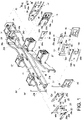
FIG. 1 andFIG. 2 , thecable management device 20 according to an embodiment of the present invention includes a firstcable management arm 22, a secondcable management arm 24, afirst component 26, and asecond component 28. Preferably, thecable management device 20 further includes a firstengaging member 30 and afirst coupling member 32. - The first
cable management arm 22 includes afirst end portion 22a and asecond end portion 22b away from thefirst end portion 22a. - The second
cable management arm 24 can be moved with respect to the firstcable management arm 22. The secondcable management arm 24 includes afirst end portion 24a and asecond end portion 24b away from thefirst end portion 24a. More specifically, the secondcable management arm 24 is pivotally connected with respect to the firstcable management arm 22. For example, the secondcable management arm 24 is pivotally connected to the firstcable management arm 22 at a position adjacent to thesecond end portion 22b of the firstcable management arm 22. More specifically, thesecond end portion 24b of the secondcable management arm 24 and thesecond end portion 22b of the firstcable management arm 22 are pivotally connected with respect to each other. Here, by way of example, apivotal connection base 34 is pivotally connected to thesecond end portion 22b of the firstcable management arm 22 and thesecond end portion 24b of the secondcable management arm 24 via twoshafts cable management arm 22, the secondcable management arm 24, and thepivotal connection base 34 is provided with acable accommodating feature 37. Here, each of the firstcable management arm 22, the secondcable management arm 24, and thepivotal connection base 34 is provided with at least onecable accommodating feature 37 by way of example. - The
first component 26 is pivotally connected with respect to the firstcable management arm 22, wherein the pivotal connection may be formed either directly or indirectly. Here, thefirst component 26 is pivotally connected to the firstcable management arm 22 at a position adjacent to thefirst end portion 22a of the firstcable management arm 22 via a firstpivotal connection element 38 by way of example but not limitation. - The
second component 28 can be displaced with respect to thefirst component 26. Preferably, thesecond component 28 and thefirst component 26 are movably mounted with respect to each other through achannel 40. Here, by way of example, thesecond component 28 includes afirst wall 42a, asecond wall 42b, and amiddle wall 44 connected between thefirst wall 42a and thesecond wall 42b; and thefirst wall 42a, thesecond wall 42b, and themiddle wall 44 of thesecond component 28 jointly define thechannel 40 for accommodating thefirst component 26. Preferably, thefirst component 26 includes afirst guiding feature 46, and thesecond component 28 is additionally equipped, or integrally formed, with afirst projection 48. Thefirst projection 48 is located in a portion of thefirst guiding feature 46 so that thesecond component 28 can be displaced with respect to thefirst component 26 to a limited extent. In this embodiment, thefirst guiding feature 46 is a slot or elongated groove with a boundary, and thefirst projection 48 has abody 48a and ahead 48b. Thebody 48a extends through a portion of thefirst guiding feature 46 and is connected to thesecond component 28. Thehead 48b is larger than thebody 48a and is stopped on one side of thefirst component 26. In practice, however, thefirst guiding feature 46 and thefirst projection 48 are not necessarily so configured. For example, thefirst projection 48 may be formed as a rib instead. - The first engaging
member 30 is disposed on one of thefirst component 26 and thesecond component 28. Here, the first engagingmember 30 is disposed on thefirst component 26 by way of example. The first engagingmember 30 is configured to engage with the other of thefirst component 26 and thesecond component 28. Here, the first engagingmember 30 is configured to engage with thesecond component 28 by way of example. Preferably, the first engagingmember 30 includes afirst fixing portion 30a, a firstelastic arm 30b, and a first engagingportion 30c. Thefirst fixing portion 30a is connected to thefirst component 26. The firstelastic arm 30b extends from thefirst fixing portion 30a. The firstengaging portion 30c is disposed on the firstelastic arm 30b and is, for example, a protruding block (or hook) for engaging with any one of a plurality of different portions of thesecond component 28. For example, the first engagingportion 30c is configured to engage with afirst feature 28a or asecond feature 28b of thesecond component 28, wherein thefirst feature 28a and thesecond feature 28b are preferably holes or grooves. - The
first coupling member 32 is disposed on thesecond component 28. In this embodiment, thefirst coupling member 32 is pivotally connected with respect to thesecond component 28. For example, thefirst coupling member 32 is pivotally connected to thesecond component 28 at a position adjacent to an end portion of thesecond component 28 via a secondpivotal connection element 50. In practice, however, thefirst coupling member 32 is not necessarily so connected. - The
cable management device 20 further includes athird component 52, afourth component 54, and a second engagingmember 56. Thecable management device 20 further includes asecond coupling member 58. - The
third component 52 is pivotally connected with respect to the secondcable management arm 24, wherein the pivotal connection may be formed either directly or indirectly. Here, thethird component 52 is pivotally connected to the secondcable management arm 24 at a position adjacent to thefirst end portion 24a of the secondcable management arm 24 via a thirdpivotal connection element 60 by way of example but not limitation. - The
fourth component 54 can be displaced with respect to thethird component 52. Preferably, thefourth component 54 and thethird component 52 are movably mounted with respect to each other through achannel 62. Here, by way of example, thefourth component 54 includes afirst wall 64a, asecond wall 64b, and amiddle wall 66 connected between thefirst wall 64a and thesecond wall 64b; and thefirst wall 64a, thesecond wall 64b, and themiddle wall 66 of thefourth component 54 jointly define thechannel 62 for accommodating thethird component 52. Preferably, thethird component 52 includes asecond guiding feature 68, and thefourth component 54 is additionally equipped, or integrally formed, with asecond projection 70. Thesecond projection 70 is located in a portion of thesecond guiding feature 68 so that thefourth component 54 can be displaced with respect to thethird component 52 to a limited extent. In this embodiment, thesecond guiding feature 68 is a slot or elongated groove with a boundary, and thesecond projection 70 has abody 70a and ahead 70b. Thebody 70a extends through a portion of thesecond guiding feature 68 and is connected to thefourth component 54. Thehead 70b is larger than thebody 70a and is stopped on one side of thethird component 52. In practice, however, thesecond guiding feature 68 and thesecond projection 70 are not necessarily so configured. For example, thesecond projection 70 may be formed as a rib instead. - The second engaging
member 56 is disposed on one of thethird component 52 and thefourth component 54. Here, the second engagingmember 56 is arranged on thethird component 52 by way of example. The second engagingmember 56 is configured to engage with the other of thethird component 52 and thefourth component 54. Here, the second engagingmember 56 is configured to engage with thefourth component 54 by way of example. Preferably, the second engagingmember 56 includes asecond fixing portion 56a, a secondelastic arm 56b, and a secondengaging portion 56c. Thesecond fixing portion 56a is connected to thethird component 52. The secondelastic arm 56b extends from thesecond fixing portion 56a. The secondengaging portion 56c is disposed on the secondelastic arm 56b and is, for example, a protruding block (or hook) for engaging with any one of a plurality of different portions of thefourth component 54. For example, the second engagingportion 56c is configured to engage with afirst feature 54a or asecond feature 54b of thefourth component 54, wherein thefirst feature 54a and thesecond feature 54b are preferably holes or grooves. - The
second coupling member 58 is disposed on thefourth component 54. In this embodiment, thesecond coupling member 58 is pivotally connected with respect to thefourth component 54. For example, thesecond coupling member 58 is pivotally connected to thefourth component 54 at a position adjacent to an end portion of thefourth component 54 via a fourthpivotal connection element 72. In practice, however, thesecond coupling member 58 is not necessarily so connected. - Preferably, the
cable management device 20 further includes a supportingmember 74, a mountingbase 76, and athird coupling member 78. - The supporting
member 74 has a predetermined length and is movably disposed below the firstcable management arm 22 and the secondcable management arm 24 in order to support one of the firstcable management arm 22 and the secondcable management arm 24. Here, the supportingmember 74 is connected to a bottom portion of thepivotal connection base 34 by way of example. The mountingbase 76 is pivotally connected to a supportingbase 75 via a mountingmember 81, wherein the supportingbase 75 is connected to the supportingmember 74. Thethird coupling member 78 can be displaced with respect to the mountingbase 76. Preferably, the mountingbase 76 includes at least onethird guiding feature 80, and thethird coupling member 78 is additionally equipped, or integrally formed, with at least onethird projection 82. The at least onethird projection 82 is located in a portion of the at least onethird guiding feature 80 so that thethird coupling member 78 can be displaced with respect to the mountingbase 76 to a limited extent. In this embodiment, the at least onethird guiding feature 80 is a slot or elongated groove with a boundary, and the at least onethird projection 82 has abody 82a and ahead 82b. Thebody 82a extends through a portion of the at least onethird guiding feature 80 and is connected to thethird coupling member 78. Thehead 82b is larger than thebody 82a and is stopped on one side of the mountingbase 76. In practice, however, the at least onethird guiding feature 80 and the at least onethird projection 82 are not necessarily so configured. For example, the at least onethird projection 82 may be formed as a rib instead. - Preferably, the
cable management device 20 further includes a third engagingmember 84. The third engagingmember 84 is disposed on one of the mountingbase 76 and thethird coupling member 78. Here, the third engagingmember 84 is disposed on the mountingbase 76 by way of example. The third engagingmember 84 is configured to engage with the other of the mountingbase 76 and thethird coupling member 78. Here, the third engagingmember 84 is configured to engage with thethird coupling member 78 by way of example. Preferably, the third engagingmember 84 includes athird fixing portion 84a, a thirdelastic arm 84b, and a thirdengaging portion 84c. Thethird fixing portion 84a is connected to the mountingbase 76. The thirdelastic arm 84b extends from thethird fixing portion 84a. The thirdengaging portion 84c is disposed on the thirdelastic arm 84b and is, for example, a protruding block (or hook) for engaging with any one of a plurality of different portions of thethird coupling member 78. For example, the third engagingportion 84c is configured to engage with at least onefirst feature 78a or at least onesecond feature 78b of thethird coupling member 78, wherein the at least onefirst feature 78a and the at least onesecond feature 78b are preferably holes or grooves. It is worth mentioning that the mountingbase 76, thefirst component 26, and thethird component 52 are all pivotable and can be pointed in the same direction. - As shown in
FIG. 2 , the second component 28 (together with the first coupling member 32) can arrive at a corresponding first position P1 with respect to the first component 26 (see alsoFIG. 3 ), the fourth component 54 (together with the second coupling member 58) can arrive at a corresponding first position P1 with respect to thethird component 52, and thethird coupling member 78 can arrive at a corresponding first position P1 with respect to the mountingbase 76. - As shown in
FIG. 3 and FIG. 4 , the second component 28 (together with the first coupling member 32) can be displaced with respect to thefirst component 26 from the corresponding first position P1 to a corresponding second position P2. Similarly, the fourth component 54 (together with the second coupling member 58) can be displaced with respect to thethird component 52 from the corresponding first position P1 inFIG. 2 to a corresponding second position (not shown). - Please note that the first engaging
member 30 can engage with thesecond component 28 to keep the second component 28 (and the first coupling member 32) at one of a plurality of different positions with respect to thefirst component 26. For example, when the second component 28 (and the first coupling member 32) are at the corresponding first position P1 with respect to thefirst component 26, the first engagingportion 30c of the first engagingmember 30 can be brought into engagement with thefirst feature 28a of thesecond component 28 to keep thesecond component 28 at the corresponding first position P1 as shown inFIG. 3 , and when the second component 28 (and the first coupling member 32) are at the corresponding second position P2 with respect to thefirst component 26, the first engagingportion 30c of the first engagingmember 30 can be brought into engagement with thesecond feature 28b of thesecond component 28 to keep thesecond component 28 at the corresponding second position P2 as shown inFIG. 4 . - It is worth mentioning that, when the
second component 28 is at the corresponding first position P1 with respect to thefirst component 26, thesecond component 28 and thefirst component 26 define a first length L1 (seeFIG. 3 ). Here, with thefirst coupling member 32 disposed on thesecond component 28, the first length L1 is shown as extending between the front end of thefirst coupling member 32 and the rear end of thefirst component 26 by way of example. Similarly, when thesecond component 28 is at the corresponding second position P2 with respect to thefirst component 26, thesecond component 28 and thefirst component 26 define a second length L2 (seeFIG. 4 ), wherein the second length L2 is different from the first length L1. Here, with thefirst coupling member 32 disposed on thesecond component 28, the second length L2 is shown as extending between the front end of thefirst coupling member 32 and the rear end of thefirst component 26 by way of example, and the second length L2 is greater than the first length L1. - Likewise, as shown in
FIG. 2 andFIG. 1 , the second engagingportion 56c of the second engagingmember 56 can be brought into engagement with thefirst feature 54a or thesecond feature 54b of thefourth component 54 to keep the fourth component 54 (and the second coupling member 58) at the corresponding first position P1 or the corresponding second position, and thefourth component 54 and thethird component 52 define different lengths when thefourth component 54 arrives respectively at the corresponding second position from the corresponding first position P1 with respect to thethird component 52 and at the corresponding first position P1 from the corresponding second position. - Referring to
FIG. 5 and FIG. 6 in conjunction withFIG. 2 , thethird coupling member 78 can be displaced with respect to the mountingbase 76 from the corresponding first position P1 to a corresponding second position P2. When thethird coupling member 78 is at the corresponding first position PI, the third engagingportion 84c of the third engagingmember 84 can be brought into engagement with the at least onefirst feature 78a of thethird coupling member 78 to keep thethird coupling member 78 at the corresponding first position PI, thereby defining a first length E1 between the front end of thethird coupling member 78 and the rear end of the mountingbase 76. When thethird coupling member 78 is at the corresponding second position P2, the third engagingportion 84c of the third engagingmember 84 can be brought into engagement with the at least onesecond feature 78b of thethird coupling member 78 to keep thethird coupling member 78 at the corresponding second position P2, thereby defining a second length E2 between the front end of thethird coupling member 78 and the rear end of the mountingbase 76, wherein the second length E2 is different from the first length E1. Here, the second length E2 is greater than the first length E1. -
FIG. 7 shows a rack system that includes thecable management device 20, a first slide rail assembly 86 (referred to as a slide rail assembly in the claims), and a second slide rail assembly 88 (referred to as another slide rail assembly in the claims). Thecable management device 20 and the firstslide rail assembly 86 constitute a coupling assembly. The firstslide rail assembly 86 includes afirst rail 90 and asecond rail 92 longitudinally displaceable with respect to thefirst rail 90. Thefirst rail 90 is, for example, fixed on afirst post 94a and asecond post 94b of a rack, and thesecond rail 92 can be displaced with respect to thefirst rail 90. Preferably, the firstslide rail assembly 86 further includes amiddle rail 96 movably mounted between thefirst rail 90 and thesecond rail 92 to increase the distance for which thesecond rail 92 can be displaced with respect to thefirst rail 90. Similarly, the secondslide rail assembly 88 includes athird rail 98 and afourth rail 100; thethird rail 98 is, for example, fixed on anotherfirst post 94c and anothersecond post 94d of the rack; and thefourth rail 100 can be displaced with respect to thethird rail 98. - The first
cable management arm 22 of thecable management device 20 is coupled to a first target object through thefirst coupling member 32. Here, the first target object is thefirst rail 90 of the firstslide rail assembly 86, such as but not limited to a rear end portion of thefirst rail 90. The first target object may alternatively be thesecond post 94b, a bracket, or other objects where the firstcable management arm 22 can be mounted. The secondcable management arm 24 is coupled to a second target object such as thesecond rail 92 of the firstslide rail assembly 86. Here, the secondcable management arm 24 is coupled to thesecond rail 92 of the first slide rail assembly 86 (such as but not limited to a rear end portion of the second rail 92) through thesecond coupling member 58. The second target object may alternatively be a piece of electronic equipment (as described further below), a chassis (as described further below), or other movable objects. In addition, the supportingmember 74 includes a first supportingportion 74a and a second supportingportion 74b that are retractable/extensible with respect to each other. As shown inFIG. 7 (see alsoFIG. 2 ), thethird coupling member 78 is coupled to a third target object such as thethird rail 98 of the secondslide rail assembly 88. Here, thethird coupling member 78 is coupled to a rear end portion of thethird rail 98, but in practice thethird coupling member 78 may alternatively be coupled to thesecond post 94d, a bracket, or other objects where thethird coupling member 78 can be mounted. - A piece of electronic equipment 102 (or a chassis) is mounted between the first
slide rail assembly 86 and the secondslide rail assembly 88. Theelectronic equipment 102 can be pulled in a first direction D1 from inside the rack to outside the rack via thesecond rail 92 and thefourth rail 100 and thus be displaced out of the rack. During the process, the secondcable management arm 24 is opened with respect to the firstcable management arm 22 in response to thesecond rail 92 of the first slide rail assembly 86 (or the electronic equipment 102) being displaced in the first direction D1. Thecable accommodating features 37 can be used to receive the cables trailing behind theelectronic equipment 102. (A person of ordinary skill in the art should be able to understand how cables are received in the cable accommodating features 37, so further description is omitted for the sake of brevity.) Also, the supportingmember 74 can support the firstcable management arm 22 or the secondcable management arm 24. - As shown in
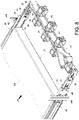
FIG. 8 , theelectronic equipment 102 can be pushed in a second direction D2 from outside the rack to inside the rack. During the process, the secondcable management arm 24 is brought close to (or closed with respect to) the firstcable management arm 22 in response to thesecond rail 92 of the first slide rail assembly 86 (or the electronic equipment 102) being displaced in the second direction D2, with the supportingmember 74 supporting the firstcable management arm 22 or the secondcable management arm 24. - More specifically, the first
cable management arm 22 inFIG. 8 is in a closed state with respect to the secondcable management arm 24. When the second component 28 (and the first coupling member 32) are at the corresponding first position P1 with respect to thefirst component 26, the fourth component 54 (and the second coupling member 58) are at the corresponding first position P1 with respect to thethird component 52, and/or thethird coupling member 78 is at the corresponding first position P1 with respect to the mountingbase 76, a first space S1 is defined between the rear side of theelectronic equipment 102 and (the secondcable management arm 24 of) thecable management device 20. The first space S 1, however, may not be large enough for the cables trailing behind theelectronic equipment 102 or may be too narrow for a technician to arrange the cables with ease. -
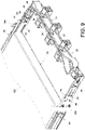
FIG. 9 shows the firstcable management arm 22 in the closed state with respect to the secondcable management arm 24 too, but a second space S2 larger than the first space S1 is defined between the rear side of theelectronic equipment 102 and (the secondcable management arm 24 of) thecable management device 20 by increasing the coupling length of the cable management device 20 (i.e., the coupling length between thecable management device 20 and theslide rail assemblies 86, 88), or more specifically by displacing the second component 28 (and the first coupling member 32) to the corresponding second position P2 with respect to thefirst component 26, the fourth component 54 (and the second coupling member 58) to the corresponding second position P2 with respect to thethird component 52, and/or thethird coupling member 78 to the corresponding second position P2 with respect to the mountingbase 76. The second space S2 provides more room for, and thus makes it easier to work with, the cables trailing behind theelectronic equipment 102. For example, the second space S2 allows a technician to arrange the cables with greater ease. - The coupling assembly described above and its cable management device preferably have the following features:
- 1. The
cable management device 20 has a mechanism (or more particularly a retractable mechanism) that allows the second component 28 (and the first coupling member 32) to be shifted in position with respect to thefirst component 26, the fourth component 54 (and the second coupling member 58) to be shifted in position with respect to thethird component 52, and/or thethird coupling member 78 to be shifted in position with respect to the mountingbase 76, thereby changing the coupling length of thecable management device 20 to solve space-related problems. - 2. The first engaging
member 30 can be used to keep the second component 28 (and the first coupling member 32) in position with respect to thefirst component 26; the second engagingmember 56 can be used to keep the fourth component 54 (and the second coupling member 58) in position with respect to thethird component 52; and the third engagingmember 84 can be used to keep thethird coupling member 78 in position with respect to the mountingbase 76. - 3. The foregoing adjustable design enables the present invention to adapt to chassis of different sizes, e.g., of different depths.
- While the present invention has been disclosed through the preferred embodiment described above, the embodiment is not intended to be restrictive of the scope of the invention. The scope of patent protection sought by the applicant is defined by the appended claims.
Claims (12)
- A cable management device (20), comprising:a first cable management arm (22); anda second cable management arm (24) pivotally connected with respect to the first cable management arm (22);characterized inthat the cable management device further comprises:a first component (26) pivotally connected with respect to the first cable management arm (22);a second component (28) displaceable with respect to the first component (26);a first engaging member (30) disposed on one of the first component (26) and the second component (28); anda first coupling member (32) pivotally connected with respect to the second component (28) and configured to mount the cable management device (20) on a first target object (90);wherein the second component (28) and the first component (26) define different lengths when the second component (28) reaches different positions after displacement with respect to the first component (26), and the first engaging member (30) is configured to engage with the other of the first component (26) and the second component (28) and thereby keep the second component (28) at one of the different positions with respect to the first component (26), andwherein the second cable management device (24) is coupled to a second target object (92) attached to an electronic component or to a rack,the cable management device (20) further comprising:a third component (52) pivotally connected with respect to the second cable management arm (24);a fourth component (54) displaceable with respect to the third component (52); anda second engaging member (56) disposed on one of the third component (52) and the fourth component (54),wherein the fourth component (54) and the third component (52) define different lengths when the fourth component (54) reaches different positions after displacement with respect to the third component (52), and the second engaging member (56) is configured to engage with the other of the third component (52) and the fourth component (54) and thereby keep the fourth component (54) at one of the different positions with respect to the third component (52), andthe cable management device (20) further comprising a second coupling member (58) pivotally connected with respect to the fourth component (54),and the second coupling member (58) is configured to mount the cable management device (20) on the second target object (92),wherein the second target object (92) can be displaced with respect to the first target object (90).
- The cable management device (20) as claimed in claim 1, wherein the first component (26) includes a first guiding feature (46), the second component (28) is provided with a first projection (48), and the first projection (48) is located in a portion of the first guiding feature (46) in order for the second component (28) to be displaceable with respect to the first component (26) to a limited extent.
- The cable management device (20) as claimed in claim 2, wherein the first guiding feature (46) is a slot or an elongated groove.
- The cable management device (20) as claimed in any of claims 1-3, wherein the first component (26) and the second component (28) are mounted with respect to each other via a channel (40).
- The cable management device (20) as claimed in any of claims 1-4, wherein the first engaging member (30) is disposed on the first component (26), the first engaging member (30) includes a first elastic arm (30b) and a first engaging portion (30c) disposed on the first elastic arm (30b), and the first engaging portion (30c) is configured to engage with either one of a first feature (28a) and a second feature (28b) of the second component (28).
- The cable management device (20) as claimed in any of claims 1-5, wherein the third component (52) includes a second guiding feature (68), the fourth component (54) is provided with a second projection (70), and the second projection (70) is located in a portion of the second guiding feature (68) in order for the fourth component (54) to be displaceable with respect to the third component (52) to a limited extent.
- The cable management device (20) as claimed in claim 6, wherein the second guiding feature (68) is a slot or an elongated groove.
- The cable management device (20) as claimed in any of claims 1-7, wherein the third component (52) and the fourth component (54) are mounted with respect to each other via a channel (62).
- The cable management device (20) as claimed in any of claims 1-8, wherein the second engaging member (56) is disposed on the third component (52), the second engaging member (56) includes a second elastic arm (56b) and a second engaging portion (56c) disposed on the second elastic arm (56b), and the second engaging portion (56c) is configured to engage with either one of a first feature (54a) and a second feature (54b) of the fourth component (54).
- The cable management device (20) as claimed in any of claims 1-9, wherein the cable management device (20) includes a supporting member (74), a mounting base (76), and a third coupling member (78); the supporting member (74) is configured to support one of the first cable management arm (22) and the second cable management arm (24); the mounting base (76) is disposed on a supporting base (75) connected to the supporting member (74); and the third coupling member (78) is displaceable with respect to the mounting base (76).
- The cable management device (20) as claimed in claim 10, wherein the mounting base (76) includes a third guiding feature (80), the third coupling member (78) is provided with a third projection (82), the third projection (82) is located in a portion of the third guiding feature (80) in order for the third coupling member (78) to be displaceable with respect to the mounting base (76) to a limited extent, and the third coupling member (78) is configured to mount the cable management device (20) on a third target object (98).
- A coupling assembly, comprising:a first slide rail assembly (86) including a first rail (90) and a second rail (92),wherein the second rail (92) is displaceable with respect to the first rail (90);a second slide rail assembly (88) including a third rail (98) and a fourth rail (100), wherein the fourth rail (100) is displaceable with respect to the third rail (98); andthe cable management device (20) according to any of claims 1-11.
Applications Claiming Priority (1)
| Application Number | Priority Date | Filing Date | Title |
|---|---|---|---|
| TW107129219A TWI677275B (en) | 2018-08-20 | 2018-08-20 | Coupling assembly and cable management device thereof |
Publications (2)
| Publication Number | Publication Date |
|---|---|
| EP3614816A1 EP3614816A1 (en) | 2020-02-26 |
| EP3614816B1 true EP3614816B1 (en) | 2022-09-14 |
Family
ID=64901941
Family Applications (1)
| Application Number | Title | Priority Date | Filing Date |
|---|---|---|---|
| EP19150042.0A Active EP3614816B1 (en) | 2018-08-20 | 2019-01-02 | Coupling assembly and cable management device thereof |
Country Status (4)
| Country | Link |
|---|---|
| US (1) | US10709033B2 (en) |
| EP (1) | EP3614816B1 (en) |
| JP (1) | JP6817348B2 (en) |
| TW (1) | TWI677275B (en) |
Families Citing this family (5)
| Publication number | Priority date | Publication date | Assignee | Title |
|---|---|---|---|---|
| TWI725461B (en) * | 2019-06-25 | 2021-04-21 | 川湖科技股份有限公司 | Cable management assembly |
| US11464130B2 (en) * | 2019-07-31 | 2022-10-04 | Hewlett Packard Enterprise Development Lp | Cable management arm extension |
| US11277933B2 (en) | 2019-07-31 | 2022-03-15 | Hewlett Packard Enterprise Development Lp | Cable management arm |
| TWI703915B (en) * | 2019-11-05 | 2020-09-01 | 川湖科技股份有限公司 | Connection mechanism and cable management device thereof |
| TWI717151B (en) * | 2019-12-12 | 2021-01-21 | 川湖科技股份有限公司 | Cable management assembly |
Family Cites Families (19)
| Publication number | Priority date | Publication date | Assignee | Title |
|---|---|---|---|---|
| US6681942B2 (en) * | 1999-10-27 | 2004-01-27 | Hewlett-Packard Development Company | Rack mount assembly |
| US6715718B1 (en) | 2002-09-25 | 2004-04-06 | King Side Works Co., Ltd. | Adjustable bracket device of a cable management arm for furniture |
| JP3903983B2 (en) * | 2003-12-24 | 2007-04-11 | ソニー株式会社 | Battery lock mechanism of electronic equipment |
| US7554819B2 (en) * | 2004-10-15 | 2009-06-30 | King Slide Works Co., Ltd. | Cable management arm assembly |
| TW200912172A (en) * | 2007-09-06 | 2009-03-16 | King Slide Works Co Ltd | Supporting device of wire-arranging frame |
| TWI425903B (en) * | 2011-06-10 | 2014-02-01 | King Slide Technology Co Ltd | Connecting device of a cable management arm |
| TWI446665B (en) * | 2012-02-21 | 2014-07-21 | King Slide Works Co Ltd | Connection device for connecting a cable management arm to a slide rail |
| US9144174B2 (en) * | 2012-12-07 | 2015-09-22 | King Slide Works Co., Ltd. | Cable management arm assembly |
| US9281676B2 (en) | 2013-09-12 | 2016-03-08 | King Slide Works Co., Ltd. | Adjustment device for cable management arm |
| JP3187607U (en) * | 2013-09-25 | 2013-12-05 | 川湖科技股▲分▼有限公司 | Adjustment device and cable management arm using the same |
| JP6241263B2 (en) * | 2013-12-20 | 2017-12-06 | 富士通株式会社 | Electronic device, rail structure and rack |
| US9480182B2 (en) * | 2014-12-30 | 2016-10-25 | King Slide Works Co., Ltd. | Cable management arm |
| US9640961B2 (en) * | 2015-01-28 | 2017-05-02 | King Slide Works Co., Ltd. | Cable management assembly |
| TWI544861B (en) * | 2015-02-17 | 2016-08-01 | The improved structure of the management device | |
| US9635942B2 (en) | 2015-03-26 | 2017-05-02 | King Slide Works Co., Ltd. | Slide rail assembly |
| TWI556711B (en) * | 2015-05-05 | 2016-11-01 | King Slide Works Co Ltd | Cable management device |
| TWI605328B (en) * | 2016-08-12 | 2017-11-11 | 川湖科技股份有限公司 | Cable management assembly and cable management device thereof |
| TWI634829B (en) * | 2017-08-18 | 2018-09-01 | 川湖科技股份有限公司 | Cable management device and coupling assembly for rack system |
| TWI670910B (en) * | 2017-11-13 | 2019-09-01 | 川湖科技股份有限公司 | Coupling assembly and cable management device thereof |
-
2018
- 2018-08-20 TW TW107129219A patent/TWI677275B/en active
- 2018-12-24 US US16/231,782 patent/US10709033B2/en active Active
-
2019
- 2019-01-02 EP EP19150042.0A patent/EP3614816B1/en active Active
- 2019-01-29 JP JP2019012644A patent/JP6817348B2/en active Active
Also Published As
| Publication number | Publication date |
|---|---|
| TWI677275B (en) | 2019-11-11 |
| JP6817348B2 (en) | 2021-01-20 |
| EP3614816A1 (en) | 2020-02-26 |
| TW202010382A (en) | 2020-03-01 |
| US10709033B2 (en) | 2020-07-07 |
| JP2020031205A (en) | 2020-02-27 |
| US20200060040A1 (en) | 2020-02-20 |
Similar Documents
| Publication | Publication Date | Title |
|---|---|---|
| EP3614816B1 (en) | Coupling assembly and cable management device thereof | |
| EP3082387B1 (en) | Slide rail assembly | |
| EP3398481B1 (en) | Slide rail assembly | |
| EP3094165B1 (en) | Slide rail assembly | |
| EP3335590A1 (en) | Support structure for support bracket and rail | |
| EP3122164A1 (en) | Slide rail assembly and bracket device thereof | |
| EP3154320A2 (en) | Slide rail assembly and bracket device thereof | |
| EP3352547B1 (en) | Slide rail assembly | |
| US20160097229A1 (en) | Slide rail assembly | |
| EP3199061A1 (en) | Slide rail assembly | |
| EP3332670B1 (en) | Adjustable slide rail mechanism for drawers | |
| EP3193569A1 (en) | Bracket device | |
| TWI481364B (en) | Slide rail assembly for use in a rack system | |
| EP3440961A1 (en) | Slide rail assembly and rail kit thereof | |
| EP3567994B1 (en) | Slide rail assembly and slide rail kit thereof | |
| EP3258754A1 (en) | Rack system and slide rail assemblies thereof | |
| US11134583B2 (en) | Slide rail mechanism and supporting assembly thereof | |
| EP3041329A1 (en) | Cable management arm | |
| EP3076774B1 (en) | Slide rail assembly | |
| EP3700310B1 (en) | Slide rail mechanism and supporting assembly thereof | |
| CN110856379B (en) | Connection assembly and wire arranging device thereof | |
| EP3836324A1 (en) | Cable management assembly | |
| EP3058847B1 (en) | Slide rail assembly | |
| CN116548753A (en) | Sliding rail assembly | |
| EP3478042B1 (en) | Slide rail mechanism |
Legal Events
| Date | Code | Title | Description |
|---|---|---|---|
| PUAI | Public reference made under article 153(3) epc to a published international application that has entered the european phase |
Free format text: ORIGINAL CODE: 0009012 |
|
| STAA | Information on the status of an ep patent application or granted ep patent |
Free format text: STATUS: REQUEST FOR EXAMINATION WAS MADE |
|
| 17P | Request for examination filed |
Effective date: 20191106 |
|
| AK | Designated contracting states |
Kind code of ref document: A1 Designated state(s): AL AT BE BG CH CY CZ DE DK EE ES FI FR GB GR HR HU IE IS IT LI LT LU LV MC MK MT NL NO PL PT RO RS SE SI SK SM TR |
|
| AX | Request for extension of the european patent |
Extension state: BA ME |
|
| STAA | Information on the status of an ep patent application or granted ep patent |
Free format text: STATUS: EXAMINATION IS IN PROGRESS |
|
| 17Q | First examination report despatched |
Effective date: 20210512 |
|
| GRAP | Despatch of communication of intention to grant a patent |
Free format text: ORIGINAL CODE: EPIDOSNIGR1 |
|
| STAA | Information on the status of an ep patent application or granted ep patent |
Free format text: STATUS: GRANT OF PATENT IS INTENDED |
|
| INTG | Intention to grant announced |
Effective date: 20220406 |
|
| GRAS | Grant fee paid |
Free format text: ORIGINAL CODE: EPIDOSNIGR3 |
|
| GRAA | (expected) grant |
Free format text: ORIGINAL CODE: 0009210 |
|
| STAA | Information on the status of an ep patent application or granted ep patent |
Free format text: STATUS: THE PATENT HAS BEEN GRANTED |
|
| AK | Designated contracting states |
Kind code of ref document: B1 Designated state(s): AL AT BE BG CH CY CZ DE DK EE ES FI FR GB GR HR HU IE IS IT LI LT LU LV MC MK MT NL NO PL PT RO RS SE SI SK SM TR |
|
| REG | Reference to a national code |
Ref country code: GB Ref legal event code: FG4D |
|
| REG | Reference to a national code |
Ref country code: CH Ref legal event code: EP |
|
| REG | Reference to a national code |
Ref country code: DE Ref legal event code: R096 Ref document number: 602019019459 Country of ref document: DE |
|
| REG | Reference to a national code |
Ref country code: IE Ref legal event code: FG4D |
|
| REG | Reference to a national code |
Ref country code: AT Ref legal event code: REF Ref document number: 1519492 Country of ref document: AT Kind code of ref document: T Effective date: 20221015 |
|
| REG | Reference to a national code |
Ref country code: LT Ref legal event code: MG9D |
|
| REG | Reference to a national code |
Ref country code: NL Ref legal event code: MP Effective date: 20220914 |
|
| PG25 | Lapsed in a contracting state [announced via postgrant information from national office to epo] |
Ref country code: SE Free format text: LAPSE BECAUSE OF FAILURE TO SUBMIT A TRANSLATION OF THE DESCRIPTION OR TO PAY THE FEE WITHIN THE PRESCRIBED TIME-LIMIT Effective date: 20220914 Ref country code: RS Free format text: LAPSE BECAUSE OF FAILURE TO SUBMIT A TRANSLATION OF THE DESCRIPTION OR TO PAY THE FEE WITHIN THE PRESCRIBED TIME-LIMIT Effective date: 20220914 Ref country code: NO Free format text: LAPSE BECAUSE OF FAILURE TO SUBMIT A TRANSLATION OF THE DESCRIPTION OR TO PAY THE FEE WITHIN THE PRESCRIBED TIME-LIMIT Effective date: 20221214 Ref country code: LV Free format text: LAPSE BECAUSE OF FAILURE TO SUBMIT A TRANSLATION OF THE DESCRIPTION OR TO PAY THE FEE WITHIN THE PRESCRIBED TIME-LIMIT Effective date: 20220914 Ref country code: LT Free format text: LAPSE BECAUSE OF FAILURE TO SUBMIT A TRANSLATION OF THE DESCRIPTION OR TO PAY THE FEE WITHIN THE PRESCRIBED TIME-LIMIT Effective date: 20220914 Ref country code: FI Free format text: LAPSE BECAUSE OF FAILURE TO SUBMIT A TRANSLATION OF THE DESCRIPTION OR TO PAY THE FEE WITHIN THE PRESCRIBED TIME-LIMIT Effective date: 20220914 |
|
| PGFP | Annual fee paid to national office [announced via postgrant information from national office to epo] |
Ref country code: IE Payment date: 20221201 Year of fee payment: 5 Ref country code: GB Payment date: 20221201 Year of fee payment: 5 |
|
| REG | Reference to a national code |
Ref country code: AT Ref legal event code: MK05 Ref document number: 1519492 Country of ref document: AT Kind code of ref document: T Effective date: 20220914 |
|
| PG25 | Lapsed in a contracting state [announced via postgrant information from national office to epo] |
Ref country code: HR Free format text: LAPSE BECAUSE OF FAILURE TO SUBMIT A TRANSLATION OF THE DESCRIPTION OR TO PAY THE FEE WITHIN THE PRESCRIBED TIME-LIMIT Effective date: 20220914 Ref country code: GR Free format text: LAPSE BECAUSE OF FAILURE TO SUBMIT A TRANSLATION OF THE DESCRIPTION OR TO PAY THE FEE WITHIN THE PRESCRIBED TIME-LIMIT Effective date: 20221215 |
|
| PG25 | Lapsed in a contracting state [announced via postgrant information from national office to epo] |
Ref country code: SM Free format text: LAPSE BECAUSE OF FAILURE TO SUBMIT A TRANSLATION OF THE DESCRIPTION OR TO PAY THE FEE WITHIN THE PRESCRIBED TIME-LIMIT Effective date: 20220914 Ref country code: RO Free format text: LAPSE BECAUSE OF FAILURE TO SUBMIT A TRANSLATION OF THE DESCRIPTION OR TO PAY THE FEE WITHIN THE PRESCRIBED TIME-LIMIT Effective date: 20220914 Ref country code: PT Free format text: LAPSE BECAUSE OF FAILURE TO SUBMIT A TRANSLATION OF THE DESCRIPTION OR TO PAY THE FEE WITHIN THE PRESCRIBED TIME-LIMIT Effective date: 20230116 Ref country code: ES Free format text: LAPSE BECAUSE OF FAILURE TO SUBMIT A TRANSLATION OF THE DESCRIPTION OR TO PAY THE FEE WITHIN THE PRESCRIBED TIME-LIMIT Effective date: 20220914 Ref country code: CZ Free format text: LAPSE BECAUSE OF FAILURE TO SUBMIT A TRANSLATION OF THE DESCRIPTION OR TO PAY THE FEE WITHIN THE PRESCRIBED TIME-LIMIT Effective date: 20220914 Ref country code: AT Free format text: LAPSE BECAUSE OF FAILURE TO SUBMIT A TRANSLATION OF THE DESCRIPTION OR TO PAY THE FEE WITHIN THE PRESCRIBED TIME-LIMIT Effective date: 20220914 |
|
| PG25 | Lapsed in a contracting state [announced via postgrant information from national office to epo] |
Ref country code: SK Free format text: LAPSE BECAUSE OF FAILURE TO SUBMIT A TRANSLATION OF THE DESCRIPTION OR TO PAY THE FEE WITHIN THE PRESCRIBED TIME-LIMIT Effective date: 20220914 Ref country code: PL Free format text: LAPSE BECAUSE OF FAILURE TO SUBMIT A TRANSLATION OF THE DESCRIPTION OR TO PAY THE FEE WITHIN THE PRESCRIBED TIME-LIMIT Effective date: 20220914 Ref country code: IS Free format text: LAPSE BECAUSE OF FAILURE TO SUBMIT A TRANSLATION OF THE DESCRIPTION OR TO PAY THE FEE WITHIN THE PRESCRIBED TIME-LIMIT Effective date: 20230114 Ref country code: EE Free format text: LAPSE BECAUSE OF FAILURE TO SUBMIT A TRANSLATION OF THE DESCRIPTION OR TO PAY THE FEE WITHIN THE PRESCRIBED TIME-LIMIT Effective date: 20220914 |
|
| PGFP | Annual fee paid to national office [announced via postgrant information from national office to epo] |
Ref country code: DE Payment date: 20230113 Year of fee payment: 5 |
|
| REG | Reference to a national code |
Ref country code: DE Ref legal event code: R097 Ref document number: 602019019459 Country of ref document: DE |
|
| PG25 | Lapsed in a contracting state [announced via postgrant information from national office to epo] |
Ref country code: NL Free format text: LAPSE BECAUSE OF FAILURE TO SUBMIT A TRANSLATION OF THE DESCRIPTION OR TO PAY THE FEE WITHIN THE PRESCRIBED TIME-LIMIT Effective date: 20220914 Ref country code: AL Free format text: LAPSE BECAUSE OF FAILURE TO SUBMIT A TRANSLATION OF THE DESCRIPTION OR TO PAY THE FEE WITHIN THE PRESCRIBED TIME-LIMIT Effective date: 20220914 |
|
| PLBE | No opposition filed within time limit |
Free format text: ORIGINAL CODE: 0009261 |
|
| STAA | Information on the status of an ep patent application or granted ep patent |
Free format text: STATUS: NO OPPOSITION FILED WITHIN TIME LIMIT |
|
| PG25 | Lapsed in a contracting state [announced via postgrant information from national office to epo] |
Ref country code: DK Free format text: LAPSE BECAUSE OF FAILURE TO SUBMIT A TRANSLATION OF THE DESCRIPTION OR TO PAY THE FEE WITHIN THE PRESCRIBED TIME-LIMIT Effective date: 20220914 |
|
| 26N | No opposition filed |
Effective date: 20230615 |
|
| PG25 | Lapsed in a contracting state [announced via postgrant information from national office to epo] |
Ref country code: SI Free format text: LAPSE BECAUSE OF FAILURE TO SUBMIT A TRANSLATION OF THE DESCRIPTION OR TO PAY THE FEE WITHIN THE PRESCRIBED TIME-LIMIT Effective date: 20220914 |
|
| REG | Reference to a national code |
Ref country code: CH Ref legal event code: PL |
|
| PG25 | Lapsed in a contracting state [announced via postgrant information from national office to epo] |
Ref country code: LU Free format text: LAPSE BECAUSE OF NON-PAYMENT OF DUE FEES Effective date: 20230102 |
|
| REG | Reference to a national code |
Ref country code: BE Ref legal event code: MM Effective date: 20230131 |
|
| PG25 | Lapsed in a contracting state [announced via postgrant information from national office to epo] |
Ref country code: LI Free format text: LAPSE BECAUSE OF NON-PAYMENT OF DUE FEES Effective date: 20230131 Ref country code: CH Free format text: LAPSE BECAUSE OF NON-PAYMENT OF DUE FEES Effective date: 20230131 |
|
| PG25 | Lapsed in a contracting state [announced via postgrant information from national office to epo] |
Ref country code: FR Free format text: LAPSE BECAUSE OF NON-PAYMENT OF DUE FEES Effective date: 20230131 Ref country code: BE Free format text: LAPSE BECAUSE OF NON-PAYMENT OF DUE FEES Effective date: 20230131 |
|
| PGFP | Annual fee paid to national office [announced via postgrant information from national office to epo] |
Ref country code: IE Payment date: 20240108 Year of fee payment: 6 |