EP3614698A1 - Dämpfungseinrichtung für einen hörer eines hörinstruments sowie hörinstrument mit einer solchen dämpfungseinrichtung - Google Patents
Dämpfungseinrichtung für einen hörer eines hörinstruments sowie hörinstrument mit einer solchen dämpfungseinrichtung Download PDFInfo
- Publication number
- EP3614698A1 EP3614698A1 EP19185641.8A EP19185641A EP3614698A1 EP 3614698 A1 EP3614698 A1 EP 3614698A1 EP 19185641 A EP19185641 A EP 19185641A EP 3614698 A1 EP3614698 A1 EP 3614698A1
- Authority
- EP
- European Patent Office
- Prior art keywords
- damping
- cage
- shell
- receiver
- damping device
- Prior art date
- Legal status (The legal status is an assumption and is not a legal conclusion. Google has not performed a legal analysis and makes no representation as to the accuracy of the status listed.)
- Granted
Links
Images


Classifications
-
- H—ELECTRICITY
- H04—ELECTRIC COMMUNICATION TECHNIQUE
- H04R—LOUDSPEAKERS, MICROPHONES, GRAMOPHONE PICK-UPS OR LIKE ACOUSTIC ELECTROMECHANICAL TRANSDUCERS; ELECTRIC HEARING AIDS; PUBLIC ADDRESS SYSTEMS
- H04R25/00—Electric hearing aids
- H04R25/60—Mounting or interconnection of hearing aid parts, e.g. inside tips, housings or to ossicles
-
- H—ELECTRICITY
- H04—ELECTRIC COMMUNICATION TECHNIQUE
- H04R—LOUDSPEAKERS, MICROPHONES, GRAMOPHONE PICK-UPS OR LIKE ACOUSTIC ELECTROMECHANICAL TRANSDUCERS; ELECTRIC HEARING AIDS; PUBLIC ADDRESS SYSTEMS
- H04R25/00—Electric hearing aids
- H04R25/60—Mounting or interconnection of hearing aid parts, e.g. inside tips, housings or to ossicles
- H04R25/604—Mounting or interconnection of hearing aid parts, e.g. inside tips, housings or to ossicles of acoustic or vibrational transducers
-
- H—ELECTRICITY
- H04—ELECTRIC COMMUNICATION TECHNIQUE
- H04R—LOUDSPEAKERS, MICROPHONES, GRAMOPHONE PICK-UPS OR LIKE ACOUSTIC ELECTROMECHANICAL TRANSDUCERS; ELECTRIC HEARING AIDS; PUBLIC ADDRESS SYSTEMS
- H04R25/00—Electric hearing aids
- H04R25/45—Prevention of acoustic reaction, i.e. acoustic oscillatory feedback
-
- H—ELECTRICITY
- H04—ELECTRIC COMMUNICATION TECHNIQUE
- H04R—LOUDSPEAKERS, MICROPHONES, GRAMOPHONE PICK-UPS OR LIKE ACOUSTIC ELECTROMECHANICAL TRANSDUCERS; ELECTRIC HEARING AIDS; PUBLIC ADDRESS SYSTEMS
- H04R25/00—Electric hearing aids
- H04R25/65—Housing parts, e.g. shells, tips or moulds, or their manufacture
-
- H—ELECTRICITY
- H04—ELECTRIC COMMUNICATION TECHNIQUE
- H04R—LOUDSPEAKERS, MICROPHONES, GRAMOPHONE PICK-UPS OR LIKE ACOUSTIC ELECTROMECHANICAL TRANSDUCERS; ELECTRIC HEARING AIDS; PUBLIC ADDRESS SYSTEMS
- H04R25/00—Electric hearing aids
- H04R25/70—Adaptation of deaf aid to hearing loss, e.g. initial electronic fitting
-
- H—ELECTRICITY
- H04—ELECTRIC COMMUNICATION TECHNIQUE
- H04R—LOUDSPEAKERS, MICROPHONES, GRAMOPHONE PICK-UPS OR LIKE ACOUSTIC ELECTROMECHANICAL TRANSDUCERS; ELECTRIC HEARING AIDS; PUBLIC ADDRESS SYSTEMS
- H04R2225/00—Details of deaf aids covered by H04R25/00, not provided for in any of its subgroups
- H04R2225/025—In the ear hearing aids [ITE] hearing aids
-
- H—ELECTRICITY
- H04—ELECTRIC COMMUNICATION TECHNIQUE
- H04R—LOUDSPEAKERS, MICROPHONES, GRAMOPHONE PICK-UPS OR LIKE ACOUSTIC ELECTROMECHANICAL TRANSDUCERS; ELECTRIC HEARING AIDS; PUBLIC ADDRESS SYSTEMS
- H04R25/00—Electric hearing aids
- H04R25/45—Prevention of acoustic reaction, i.e. acoustic oscillatory feedback
- H04R25/456—Prevention of acoustic reaction, i.e. acoustic oscillatory feedback mechanically
Definitions
- the invention relates to a damping device for vibration-damping (vibration-damping) mounting of a listener within a hearing instrument.
- the invention further relates to a hearing instrument with a corresponding damping device.
- hearing instruments which record ambient sound, modify them in terms of signal technology and emit a modified sound signal to the hearing of a person wearing the hearing instrument (“wearer”).
- a hearing instrument that is designed to supply a hearing-impaired wearer and processes, in particular amplifies, acoustic ambient signals in such a way that the hearing damage is compensated for in whole or in part, is referred to here and below as a “hearing aid”.
- a hearing aid usually comprises an input converter, for example in the form of a microphone, a signal processing unit with an amplifier, and an output converter.
- the output converter is usually implemented as a miniature loudspeaker and is also referred to as a "receiver”.
- hearing instruments that are aimed at the care of normal hearing, to protect the hearing of the wearer or to support sound perception (e.g. understanding speech in complex noise environments) for specific purposes.
- Such hearing instruments are often constructed similarly to hearing aids and include in particular also the above-mentioned components input converter, signal processing and output converter.
- BTE hearing instruments (behind-the-ear, also behind-the-ear, BTE for short), a housing equipped with the input converter, signal processing and a battery is worn behind the ear.
- the listener can either be arranged directly in the wearer's ear canal (so-called ex-listener hearing instruments or listener-in-the-canal, or RIC hearing instruments for short).
- the handset is arranged within the housing itself.
- a flexible sound tube also known as a "tube” directs the acoustic output signals of the listener from the housing to the ear canal (tube hearing instruments).
- ITE hearing instruments in-the-ear, also in-the-ear, ITE for short
- a housing that contains all the functional components, including the microphone and the receiver is at least partially worn in the ear canal.
- CIC Compactly-in-Canal
- a secure and, in particular, vibration-damped mounting of the listener within the housing of the hearing instrument is necessary in order to minimize the transmission of airborne and structure-borne noise within the housing and thus to avoid the occurrence of acoustic feedback as far as possible.
- the receiver of a hearing instrument is usually mounted with individually shaped bearings (for each hearing instrument model) which are adapted to the respective receiver design as well as to the available space in the hearing instrument and to the required amplification of the hearing instrument. It is common for a listener to be damped by means of a rubber band or a rubber bag which is wrapped around the rear part of the listener, so that the listener is prevented from bumping into the hard housing wall of the hearing instrument. In addition, listeners become common enclosed in plastic or metal chambers in order to avoid the transmission of airborne noise within the housing of the hearing instrument as far as possible.
- Effective damping concepts are becoming increasingly important, particularly in view of the growing standardization of manufacturing processes.
- hearing instruments are often developed nowadays as part of a device family that comprise different designs (e.g. BTE, ITE or RIC devices) with uniform components.
- device families are also developed that each have different components in a uniform housing, in particular receivers with different designs (e.g. single and double earphones) and / or different outputs.
- the vibration damping of the receiver is particularly demanding for a BTE device with a comparatively large housing, since here receivers with a shape that is poorly adapted to the installation space (but sometimes comparatively high weight and / or high performance) are stable, but with good vibration damping have to be hung up.
- the various functions of the handset suspension namely the mechanical holding function on the one hand and the vibration damping function on the other hand, are often in conflict here, since they would require contradictory designs of the handset suspension and are therefore difficult to reconcile with one another.
- a comparatively soft design of the receiver suspension would be advantageous, but this would be disadvantageous for a low-vibration mechanical mounting of the receiver.
- the invention is therefore based on the object of making it possible to mount a receiver securely and effectively in terms of vibration damping within a hearing instrument.
- the damping device according to the invention is used for vibration-damping mounting of a receiver within a hearing instrument.
- the damping device comprises an elastic damping element, a cage connected to the elastic damping element, and a shell surrounding the cage. According to the invention, both the elastic damping element and at least part of the shell have a lower hardness than the cage.
- the combination of - viewed from the inside out - soft material of the damping element, hard material of the cage and again soft material of the shell for vibration-damping suspension of listeners (in particular heavy and / or powerful listeners) is particularly advantageous.
- the material of the inner damping element can be made particularly soft due to the supporting effect of the hard cage.
- a particularly effective vibration damping, in particular at high frequencies, is thus achieved without having to accept a weakening of the mechanical mounting of the receiver.
- the soft shell is particularly effective for damping low frequencies; in particular, it prevents vibrations of the cage receiver from building up due to mechanical feedback effects.
- the shell effectively protects the handset from damage caused by mechanical shocks, for example if the hearing instrument is dropped.
- the elastic damping element is preferably made entirely or partially from an elastomeric material and particularly preferably from a fluorine elastomer and / or a fluorine-silicone elastomer.
- the degree of hardness of this elastic material preferably has a Shore hardness (Shore A) in a range between 20 and 30, and particularly preferably a Shore hardness of 25.
- the shell or its soft part are preferably also made of a fluorine elastomer and / or a fluorine-silicone elastomer.
- the degree of hardness of this elastic material of the shell preferably has a Shore hardness in a range between 50 and 60.
- the use of the fluorine elastomer "Viton" from DuPont is particularly suitable here.
- the cage which has greater hardness both in comparison to the damping element and (in whole or in part) to the shell, preferably consists of a (dimensionally stable) plastic, in particular of (reinforced or unreinforced) polyamide or polycarbonate.
- a "thermoset plastic” is a thermoset or a (non-elastomeric) thermoplastic.
- the cage in the context of the invention can also consist of a metal, for example a steel sheet.
- the shell (also referred to as a box) is formed in two parts. It consists in particular of two half-shells which are pushed from opposite sides onto the structural unit formed from the damping element and the cage.
- the two parts of the shell can consist of the same material or of different (in particular different hard) materials.
- a particularly advantageous embodiment of the invention is one in which the shell is made of a comparatively hard material, in particular a dimensionally stable plastic or metal, in a front area and of a comparatively soft material, in particular the above-mentioned elastomer material, in a rear area.
- the front area is the area of the shell which faces the sound outlet of the receiver in the installed state and on which the sound tube is inserted into the shell in a BTE device.
- the shell is preferably designed such that it has a mounting space for the listener - and thus also the damping element reinforced by the cage - encloses airtight.
- the shell is designed to be completely closed in order to generate a closed air volume in which the receiver is mounted as intended.
- the air volume closed off by the shell is advantageously used as an extension of the back volume for the listener.
- Such an expanded back volume is required in particular for earphones with higher performance and / or small earphone housings.
- the fact that the vibration of the sound-generating membrane displaces air behind the membrane is particularly noticeable.
- the membrane vibration in the air space behind the membrane would cause noticeable pressure fluctuations with brief overpressures and underpressures, which would counteract the deflection of the membrane and reduce the efficiency of the receiver (and thus in particular the sound power generated).
- powerful or particularly small listeners therefore often have a pressure equalization opening (backventing) behind the membrane, so that the air space surrounding the listener increases the back volume of the listener.
- a handset with backventing emits more airborne sound to the rear, so that a hermetic seal of the air space around the handset is useful in order to avoid crosstalk from the listener sound to the or each microphone of the hearing instrument (with the associated feedback risk). This is achieved in a particularly effective manner by the airtight design of the shell described above.
- the elastic damping element is preferably designed as a tube that completely surrounds the listener.
- the damping element is placed on the outside of the receiver around its outer circumference.
- the front and back of the listener preferably remain open.
- the elastic damping element expediently comprises holding projections which bear against the handset in the assembled state and thus clamp the handset between them.
- the retaining projections can be within the scope of the invention their size and damping properties can be adapted to the size and weight of the handset to be stored.
- the holding projections are designed as conical knobs, the distal ends of which each form a contact surface for the receiver to be supported.
- the cage is designed in such a way that it surrounds the damping element and that the outer circumference of the damping element therefore bears against an inner circumference of the cage.
- the cage is at least partially embedded in the material of the damping element. In this way, a positive connection between the material of the damping element and the material of the cage is achieved, as a result of which the soft material of the damping element is reinforced in a particularly effective manner.
- the damping element consists of a plurality of disjointed retaining projections, which are individually connected to the cage, in particular molded onto the cage.
- the hearing instrument according to the invention has a housing, a receiver and a damping device according to one of the above-described embodiments of the invention.
- the receiver is mounted in a vibration-damped manner within the housing of the hearing instrument by the damping device.
- the shell i.e. the sheathing surrounding the damping element and the cage, is particularly adapted to the inner shape of a housing recess of the hearing instrument provided for holding the listener and is at least partially in contact with a wall of the housing, so that the listener is free of play and stable via the damping device is held in an intended position.
- the damping device enables the listener to be sufficiently mobile to absorb vibration energy, in particular to be able to process (ie dissipate) in the higher frequencies.
- the surface of the shell is optionally structured, in particular notched, in order to reduce the transmission of force due to movement of the receiver to the housing of the hearing instrument surrounding the shell in the assembled state as effectively as possible.
- the structuring of the surface of the shell ensures that the shell does not rest against the entire housing wall, but only in discrete areas on the surrounding housing wall of the hearing instrument.
- the areas of the shell that are not in contact with the housing wall can deform, in particular bulge, in response to movements of the receiver, without touching the housing wall, so that a comparatively large proportion of the receiver movements can be absorbed by the shell.
- the attenuation device according to the invention is preferably used in a BTE hearing aid. Within the scope of the invention, however, it can also be used advantageously in an ITE hearing instrument, provided that there is sufficient installation space there.
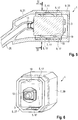
- the 1 to 3 show a first exemplary embodiment of a damping device 1, which is used for the vibration-damped mounting of a receiver 3 within a hearing instrument 4 designed as a hearing device ( Fig. 8 ) serves.
- the internal structure of the receiver 3 is shown in the sectional views 1 and 2 not shown explicitly for reasons of simplification.
- the damping device 1 comprises an elastic damping element 5, a cage 7 supporting it, and a shell 9 surrounding the cage 7.
- Fig. 4 the damping element 5 and the cage 7 with the receiver 3 stored therein are shown in isolation (ie without the surrounding shell 9).
- the cage 7 is in the 1 to 4 Embodiment shown by a tubular or tubular body 11 made of a dimensionally stable plastic, namely preferably a thermoset.
- the tubular / tube-like base body 11 has an approximately square cross section adapted to the receiver 3 and completely surrounds the side surfaces of the receiver 3.
- a sound outlet 13 of the receiver 3 and a rear side of the receiver 3 opposite the sound outlet 13, on the other hand, are arranged on the open sides of the tubular base body 11.
- the cage 7 is provided on all sides with openings 15 (that is, openings which extend from the inner circumference of the base body 11 to its outer circumference).
- the damping element 5 is in the 1 to 4 Embodiment shown from a number of unconnected holding projections in the form of hollow conical knobs 17, the distal ends (ie facing away from the inner circumference of the base body 11) each form a contact surface 19 for the receiver 3.
- the conical knobs 17 are formed from an elastic material (for example a fluorosilicone) which is softer than the material of the cage 7 and has for example a Shore hardness (Shore A) of 20-25, in particular 23.
- the cage 7 and the damping element 5 are preferably produced together in a two-component injection molding process.
- the shell 9 consists of two parts, namely a front half-shell 21 and a rear half-shell 23, these half-shells 21, 23 complementing one another to form an airtight cover for the listener 3.
- the air volume forming a mounting space for the receiver 3 and enclosed by the half-shells 21, 23 is used as an extension of the rear volume of the receiver 3 if the receiver 4 is provided with a rear opening (back venting).
- the front half-shell 21 surrounds the handset 3, which is mounted as intended, on the side on which the sound outlet 13 of the handset 3 is arranged.
- a sound tube 25 of the hearing instrument 4 is guided through this front half-shell 21 of the shell 9 and is connected to the sound outlet 13 in the interior of the shell 9 in order to transport the sound output via the sound outlet 13 to the ear of a wearer.
- the sound tube 25 a part manufactured separately from the front half-shell 21, which is pressed into an opening 26 of the front half-shell 21 (see. Fig. 1 ).
- the two half-shells 21 and 23 of the shell 9 made of elastic material (eg "Viton").
- This material is preferably chosen such that the shell 9 is harder than the knobs 17 of the damping element 5, but softer than the cage 7.
- the material of the two half-shells 21 and 23 has a Shore hardness of 55.
- the front one Half-shell 21 made from a hard material than the rear half-shell 23, in particular from a dimensionally stable plastic or from a metallic material.
- Fig. 5 An alternative embodiment of the damping device 1 is shown. This differs from the exemplary embodiment described above in that the front half-shell 21 of the shell 9 is formed in one piece (monolithic) with the sound tube 25.
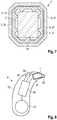
- FIG. 6 and 7 Another embodiment of the damping device 1 is shown.
- This exemplary embodiment differs from the exemplary embodiments described above in that the damping element 5 itself forms a coherent tubular body 27, from the inner circumference of which the knobs 17 protrude.
- the knobs 17 are not hollow here, but filled, so that the damping element 5 has a smooth outer circumference.
- the cage 7 is formed here by a further tubular or tubular body 29 which, in contrast to the base body 11 of the exemplary embodiment 1 to 4 but with uninterrupted side walls (i.e. without the breakthroughs 15) is executed.
- the cage 7 surrounds the damping element 5 on the outside, so that the outer circumference of the damping element 5 lies against the inner circumference of the cage 7.
- the cage 7 extends over the entire length of the damping element 5 (in Fig. 6 the cage 7 is only partially shown for better visibility of the damping element 5). Both the damping element 5 and the cage 7 are open on the front side, on which the sound outlet 13 of the receiver 3 is arranged, and on the opposite rear side.
- the damping element 5 and the cage 7 here preferably consist of those in connection with the embodiment according to FIG Fig. 1 to 4 mentioned materials.
- the cage 7 is made of a metallic material, in particular a steel sheet.
- the cage 7 is completely or partially embedded in the material of the sealing element 5.
- the hearing instrument 4 comprises a housing 33 in which the receiver 3 is mounted by means of one of the above-described embodiments of the damping device 1.
- the hearing instrument 31 further comprises two microphones 35, a battery 37 and a signal processing unit 39 (for example in the form of a digital signal processor or a microcontroller).
- the shell 9 of the damping device 1 lies at least partially against a wall 41 of the housing 33, so that the receiver 3 is mounted in the housing 33 without play via the damping device 1.
Landscapes
- Engineering & Computer Science (AREA)
- Health & Medical Sciences (AREA)
- General Health & Medical Sciences (AREA)
- Neurosurgery (AREA)
- Otolaryngology (AREA)
- Physics & Mathematics (AREA)
- Acoustics & Sound (AREA)
- Signal Processing (AREA)
- Manufacturing & Machinery (AREA)
- Telephone Set Structure (AREA)
- Vibration Prevention Devices (AREA)
- Headphones And Earphones (AREA)
Abstract
Description
- Die Erfindung betrifft eine Dämpfungseinrichtung zur schwingungsdämpfenden (vibrationsdämpfenden) Lagerung eines Hörers innerhalb eines Hörinstruments. Weiter betrifft die Erfindung ein Hörinstrument mit einer entsprechenden Dämpfungseinrichtung.
- Als "Hörinstrument" werden allgemein Geräte bezeichnet, die einen Umgebungsschall aufnehmen, signaltechnisch modifizieren und ein modifiziertes Schallsignal an das Gehör einer das Hörinstrument tragenden Person ("Träger") abgeben.
- Ein Hörinstrument, das zur Versorgung eines hörgeschädigten Trägers ausgebildet ist und das akustische Umgebungssignale derart verarbeitet, insbesondere verstärkt, dass die Hörschädigung ganz oder teilweise kompensiert wird, wird hier und im Folgenden als "Hörgerät" bezeichnet. Ein Hörgerät umfasst hierzu üblicherweise einen Eingangswandler, beispielsweise in Form eines Mikrofons, eine Signalverarbeitungseinheit mit einem Verstärker, sowie einen Ausgangswandler. Der Ausgangswandler ist in der Regel als Miniaturlautsprecher realisiert und wird auch als "Hörer" (Receiver) bezeichnet.
- Zusätzlich zu Hörgeräten gibt es allerdings auch Hörinstrumente, die auf die Versorgung von Normalhörenden ausgerichtet sind, um das Gehör des Trägers zu schützen oder um die Geräuschwahrnehmung (z.B. das Sprachverständnis in komplexen Geräuschumgebungen) für bestimmte Zwecke zu unterstützen. Solche Hörinstrumente sind oft ähnlich aufgebaut wie Hörgeräte und umfassen insbesondere auch die oben genannten Komponenten Eingangswandler, Signalverarbeitung und Ausgangswandler.
- Um den zahlreichen individuellen Bedürfnissen entgegenzukommen, werden unterschiedliche Bauformen von Hörinstrumenten angeboten. Bei sogenannten BTE-Hörinstrumenten (Behind-The-Ear, auch Hinter-dem-Ohr, kurz HdO) wird ein mit dem Eingangswandler, der Signalverarbeitung und einer Batterie bestücktes Gehäuse hinter dem Ohr getragen. Je nach Ausgestaltung kann der Hörer entweder direkt im Gehörgang des Trägers (sogenannte Ex-Hörer-Hörinstrumente oder Hörer-in-the-Canal-, kurz RIC-Hörinstrumente) angeordnet sein. Alternativ ist der Hörer innerhalb des Gehäuses selbst angeordnet. In diesem Fall leitet ein flexibler, auch als "Tube" bezeichneter Schallschlauch die akustischen Ausgabesignale des Hörers vom Gehäuse zum Gehörgang (Schlauch-Hörinstrumente). Bei sogenannten ITE-Hörinstrumenten (In-the-Ear, auch In-dem-Ohr, kurz IdO) wird ein Gehäuse, welches sämtliche funktionale Komponenten einschließlich des Mikrofons und des Hörers enthält, zumindest teilweise im Gehörgang getragen. Sogenannte CIC-Hörinstrumente (Completely-in-Canal) sind den ITE-Hörinstrumenten ähnlich, werden jedoch vollständig im Gehörgang getragen.
- Unabhängig von der Bauweise ist eine sichere und insbesondere schwingungsgedämpfte Lagerung des Hörers innerhalb des Gehäuses des Hörinstruments notwendig, um die Übertragung von Luft- und Körperschall innerhalb des Gehäuses zu minimieren und somit das Auftreten von akustischen Rückkopplungen möglichst zu vermeiden.
- Zur Erzielung einer effektiven Schwingungsdämpfung ist der Hörer eines Hörinstruments üblicherweise mit (für jedes Hörinstrumentenmodell) individuell geformten Lagerungen gelagert, die sowohl an die jeweilige Hörer-Bauform als auch an den verfügbaren Raum im Hörinstrument als auch an die geforderte Verstärkung des Hörinstruments angepasst sind. Gängig ist die Dämpfung eines Hörers mittels eines Gummibandes oder einer Gummitasche, die um den hinteren Teil des Hörers gewickelt werden, so dass ein Anstoßen des Hörers an die harte Gehäusewand des Hörinstruments vermieden wird. Zusätzlich werden Hörer häufig in Kammern aus Kunststoff oder Metall eingeschlossen, um eine Übertragung von Luftschall innerhalb des Gehäuses des Hörinstruments möglichst zu vermeiden.
- Effektiven Dämpfungskonzepten kommt insbesondere angesichts wachsender Vereinheitlichung der Herstellungsprozesse eine steigende Bedeutung zu. Insbesondere werden Hörinstrumente heutzutage häufig als Teil einer Gerätefamilie entwickelt, die verschiedene Bauformen (z.B. BTE, ITE oder RIC-Geräte) mit einheitlichen Komponenten umfassen. Umgekehrt werden auch Gerätefamilien entwickelt, die in einem einheitlichen Gehäuse jeweils unterschiedliche Komponenten, insbesondere Receiver mit unterschiedlicher Bauart (z.B. Einfach und Doppelhörer) und/oder unterschiedlicher Leistung aufweisen. In beiden Fällen ist insbesondere bei einem BTE-Gerät mit vergleichsweise großem Gehäuse die Schwingungsdämpfung des Receivers anspruchsvoll, da hier häufig Receiver mit einer an den Bauräumen schlecht angepassten Form (aber teilweise vergleichsweise hohen Gewicht und/oder hoher Leistung) stabil, aber mit guter Schwingungsdämpfung aufgehängt werden müssen. Die verschiedenen Funktionen der Höreraufhängung, nämlich einerseits die mechanische Haltefunktion und andererseits die Schwingungsdämpfungsfunktion stehen hierbei oft in Widerstreit, da sie einander widersprechende Ausbildungen der Höreraufhängung fordern würden und daher nur schwer miteinander in Einklang zu bringen sind. So wäre insbesondere im Sinne einer effektiven Schwingungsdämpfung eine vergleichsweise weiche Ausgestaltung der Höreraufhängung vorteilhaft, die aber für eine schwingungsarme mechanische Halterung des Hörers nachteilig wäre.
- Der Erfindung liegt daher die Aufgabe zugrunde, eine sichere und hinsichtlich der Schwingungsdämpfung effektive Lagerung eines Hörers innerhalb eines Hörinstruments zu ermöglichen.
- Bezüglich einer Dämpfungseinrichtung wird diese Aufgabe erfindungsgemäß gelöst durch die Merkmale des Anspruchs 1. Bezüglich eines Hörinstruments wird die Aufgabe erfindungsgemäß gelöst durch die Merkmale des Anspruchs 7. Vorteilhafte Ausgestaltungen der Erfindung sind in den Unteransprüchen und der nachfolgenden Beschreibung dargelegt.
- Die erfindungsgemäße Dämpfungseinrichtung wird zur schwingungsdämpfenden Lagerung eines Hörers innerhalb eines Hörinstruments eingesetzt. Die Dämpfungseinrichtung umfasst ein elastisches Dämpfungselement, einen mit dem elastischen Dämpfungselement verbundenen Käfig, sowie eine den Käfig umgebende Schale. Erfindungsgemäß weisen dabei sowohl das elastische Dämpfungselement als auch zumindest ein Teil der Schale eine gegenüber dem Käfig geringere Härte auf.
- Es hat sich gezeigt, dass die Kombination aus - von innen nach außen betrachtet - weichem Material des Dämpfungselements, hartem Material des Käfigs und wiederum weichem Material der Schale zur schwingungsgedämpften Aufhängung von Hörern (insbesondere schweren und/oder leistungsstarken Hörern) besonders vorteilhaft ist. Insbesondere kann das Material des inneren Dämpfungselements infolge der stützenden Wirkung des harten Käfigs besonders weich ausgebildet sein. Es wird somit eine besonders effektive Schwingungsdämpfung, insbesondere bei hohen Frequenzen, erzielt, ohne dass hierfür eine Schwächung der mechanischen Halterung des Hörers in Kauf genommen werden müsste. Die weiche Schale ist wiederum zur Dämpfung von tiefen Frequenzen besonders effektiv; sie verhindert dabei insbesondere, dass sich Schwingungen des Hörers des Käfigs durch mechanische Rückkopplungseffekte aufschaukeln. Zudem schützt die Schale den Hörer wirkungsvoll vor Beschädigung durch mechanische Stöße, beispielsweise wenn das Hörinstrument fallen gelassen wird.
- Bevorzugt ist das elastische Dämpfungselement ganz oder teilweise aus einem elastomeren Material und besonders bevorzugt aus einem Fluor-Elastomer und/oder einem Fluor-Silikon-Elastomer gefertigt. Der Härtegrad dieses elastischen Materials weist bevorzugt eine Shore-Härte (Shore A) in einem Bereich zwischen 20 und 30, und besonders bevorzugt eine Shore Härte von 25 auf.
- Die Schale oder deren weicher Teil sind bevorzugt ebenfalls aus einem Fluor-Elastomer und/oder einem Fluor-Silikon-Elastomer gefertigt. Der Härtegrad dieses elastischen Materials der Schale weist bevorzugt eine Shore-Härte in einem Bereich zwischen 50 und 60 auf. Hier eignet sich insbesondere der Einsatz des Fluor-Elastomers "Viton" der Firma DuPont.
- Der Käfig, der sowohl im Vergleich zu dem Dämpfungselement als auch (ganz oder teilweise) zu der Schale eine größere Härte aufweist, besteht vorzugsweise aus einem (formstabilen) Kunststoff, insbesondere aus (verstärktem oder unverstärktem) Polyamid oder Polycarbonat. Als "formstabiler Kunststoff" wird ein Duroplast oder ein (nicht-elastomerer) Thermoplast bezeichnet. Alternativ kann der Käfig im Rahmen der Erfindung auch aus einem Metall, beispielsweise aus einem Stahlblech, bestehen.
- In einer bevorzugten Ausführungsform ist die (auch als Box bezeichnete) Schale zweiteilig ausgebildet. Sie besteht dabei insbesondere aus zwei Halbschalen, die von entgegengesetzten Seiten auf die aus dem Dämpfungselement und dem Käfig gebildete Baueinheit aufgeschoben sind. Die beiden Teile der Schale können im Rahmen der Erfindung aus dem gleichen Material oder aus unterschiedlichen (insbesondere unterschiedlich harten) Materialien bestehen. Besonders vorteilhaft ist hierbei eine Ausführung der Erfindung, bei der die Schale in einem vorderen aus einem vergleichsweise harten Werkstoff, insbesondere einem formstabilen Kunststoff oder aus Metall, und in einem hinteren Bereich aus einem vergleichsweise weichen Werkstoff, insbesondere dem vorstehend erwähnten Elastomermaterial, gefertigt ist. Als vorderer Bereich ist dabei derjenige Bereich der Schale bezeichnet, dem im Montagezustand der Schallauslass des Hörers zugewandt ist, und an dem bei einem BTE-Gerät der Schallschlauch in die Schale eingeführt wird.
- Um die Ausbreitung des von dem Hörer (außerhalb des Schallauslasses) abgegebenen Luftschalls in dem Gehäuse des Hörinstruments weitestmöglich zu unterbinden, ist die Schale vorzugsweise derart ausgebildet, dass sie einen Montageraum für den Hörer - und damit auch das durch den Käfig verstärkte Dämpfungselement - luftdicht umschließt. Mit anderen Worten ist die Schale vollständig geschlossen ausgebildet, um ein abgeschlossenes Luftvolumen zu erzeugen, in dem der Hörer bestimmungsgemäß montiert wird. Das durch die Schale abgeschlossene Luftvolumen wird dabei vorteilhaft als Erweiterung des Rückvolumens für den Hörer genutzt.
- Ein solches erweitertes Rückvolumen wird insbesondere bei Hörern mit höherer Leistung und/oder kleinem Hörergehäuse benötigt. Bei einem solchen Hörer macht sich die Tatsache, dass die Schwingung der schallerzeugenden Membran auch hinter der Membran Luft verdrängt, besonders stark bemerkbar. Bei einem geschlossenen Hörergehäuse würde die Membranschwingung in dem Luftraum hinter der Membran (Rückvolumen) spürbare Druckschwankungen mit kurzzeitigen Über- und Unterdrücken verursachen, die der Auslenkung der Membran entgegenwirken und die Effizienz des Hörers (und somit insbesondere auch die erzeugte Schallleistung) reduzieren würden. Um die Effizienz des Hörers zu erhöhen, haben leistungsstarke oder besonders kleine Hörer daher häufig eine Druckausgleichsöffnung (Backventing) hinter der Membran, so dass der den Hörer umgebende Luftraum das Rückvolumen des Hörers vergrößert. Ein Hörer mit Backventing emittiert aber mehr Luftschall nach hinten, so dass ein hermetischer Abschluss des Luftraums um den Hörer sinnvoll ist, um ein Übersprechen des Hörerschalls auf das oder jedes Mikrofon des Hörinstruments (mit dem damit einhergehenden Rückkopplungsrisiko) zu vermeiden. Dies wird durch die vorstehend beschriebene luftdichte Ausführung der Schale auf besonders effektive Weise erreicht.
- Das elastische Dämpfungselement ist vorzugsweise als ein den Hörer vollumfänglich umschließender Schlauch ausgebildet. Mit anderen Worten ist das Dämpfungselement außenseitig des Hörers um dessen Außenumfang gelegt. Die Vorder- und die Rückseite des Hörers verbleiben hierbei bevorzugt offen.
- Das elastische Dämpfungselement umfasst zweckmäßigerweise Haltevorsprünge, die im Montagezustand an dem Hörer anliegen und somit den Hörer zwischen sich einklemmen. Die Haltevorsprünge können im Rahmen der Erfindung hinsichtlich ihrer Größe und Dämpfungseigenschaften an die Größe und das Gewicht des jeweils zu lagernden Hörers angepasst sein. In einer vorteilhaften Ausgestaltung sind die Haltevorsprünge als konische Noppen ausgebildet, deren distalen Enden jeweils eine Anlagefläche für den zu lagernden Hörer bilden.
- Der Käfig ist in einer vorteilhaften Ausgestaltung der Erfindung derart ausgebildet, dass er das Dämpfungselement umgibt, und dass somit der Außenumfang des Dämpfungselements an einem Innenumfang des Käfigs anliegt. In einer ebenfalls bevorzugten Alternativausführung ist der Käfig zumindest teilweise in das Material des Dämpfungselementes eingebettet. Hierdurch wird ein Formschluss zwischen dem Material des Dämpfungselements und dem Material des Käfigs erzielt, wodurch das weiche Material des Dämpfungselements in besonders effektiver Weise verstärkt wird. In einer weiteren Alternativausführung besteht das Dämpfungselement aus mehreren unzusammenhängenden Haltevorsprüngen, die einzeln mit dem Käfig verbunden, insbesondere an den Käfig angespritzt, sind.
- Das erfindungsgemäße Hörinstrument weist ein Gehäuse, einen Hörer und eine Dämpfungseinrichtung gemäß einer der vorbeschriebenen Ausgestaltungen der Erfindung auf. Der Hörer ist durch die Dämpfungseinrichtung schwingungsgedämpft innerhalb Gehäuses des Hörinstruments gelagert.
- Die für die erfindungsgemäße Dämpfungseinrichtung beschriebenen Vorteile und bevorzugten Ausführungsformen gelten gleichermaßen für das erfindungsgemäße Hörinstrument und können entsprechend sinngemäß auf dieses übertragen werden.
- Die Schale, also die das Dämpfungselement und den Käfig umschließende Ummantelung, ist insbesondere an die innere Form einer zur Halterung des Hörers vorgesehenen Gehäuseaussparung des Hörinstruments angepasst und liegt zumindest teilweise an einer Wandung des Gehäuses an, so dass der Hörer über die Dämpfungseinrichtung spielfrei und stabil in einer vorgesehenen Position gehalten wird. Ungeachtet der spielfreien Halterung ermöglicht die Dämpfungseinrichtung eine hinreichende Beweglichkeit des Hörers, um Vibrationsenergie, insbesondere in den höheren Frequenzen, abarbeiten (d.h. dissipieren) zu können. Die Oberfläche der Schale ist optional strukturiert, insbesondere eingekerbt, um eine Kraftübertragung aufgrund einer Bewegung des Hörers auf das die Schale im Montagezustand umgebende Gehäuse des Hörinstruments möglichst effektiv zu reduzieren. Durch die Strukturierung der Oberfläche der Schale wird erreicht, dass die Schale nicht vollflächig, sondern nur in diskreten Bereichen an der umgebenden Gehäusewand des Hörinstruments anliegt. Hierdurch können sich die nicht an der Gehäusewand anliegenden Bereiche der Schale in Reaktion auf Bewegungen des Hörers verformen, insbesondere ausbeulen, ohne die Gehäusewand zu berühren, so dass ein vergleichsweise großer Anteil der Hörerbewegungen durch die Schale aufgefangen werden kann.
- Die erfindungsgemäße Dämpfungseinrichtung wird vorzugsweise bei einem BTE-Hörgerät eingesetzt. Sie kann im Rahmen der Erfindung aber auch vorteilhaft bei einem ITE-Hörinstrument eingesetzt werden, sofern dort genügend Bauraum vorhanden ist.
- Nachfolgend werden Ausführungsbeispiele der Erfindung anhand einer Zeichnung näher erläutert. Dabei zeigen:
- Fig. 1
- in einem Längsschnitt eine Dämpfungseinrichtung mit einem elastischen Dämpfungselement, einem dieses stützenden Käfig und einer den Käfig umhüllenden Schale sowie einen in der Dämpfungseinrichtung gelagerten Hörer,
- Fig. 2
- in einem Querschnitt II-II gemäß
Fig. 1 die Dämpfungseinrichtung und den Hörer gemäßFig. 1 , - Fig. 3
- in perspektivischer Darstellung die Dämpfungseinrichtung und den Hörer gemäß
Fig. 1 , - Fig. 4
- in perspektivischer isolierter Darstellung das elastische Dämpfungselement und den Käfig der Dämpfungseinrichtung gemäß
Fig. 1 sowie den darin gelagerten Hörer, - Fig. 5
- in Darstellung gemäß
Fig. 1 ein alternatives Ausführungsbeispiel der Dämpfungseinrichtung mit dem darin gelagerten Hörer, - Fig. 6
- in Darstellung gemäß
Fig. 4 das elastische Dämpfungselement und den Käfig eines weiteren Ausführungsbeispiels der Dämpfungseinrichtung (wobei der Käfig hier nur teilweise dargestellt ist) sowie den darin gelagerten Hörer, - Fig. 7
- in Darstellung gemäß
Fig. 2 die Dämpfungseinrichtung gemäßFig. 6 , und - Fig. 8
- in schematischer Darstellung ein Hörinstrument mit der Dämpfungseinrichtung gemäß einer der
Fig. 1 bis 7 sowie mit dem darin gelagerten Hörer. - Einander entsprechende Teile sind in allen Figuren stets mit gleichen Bezugszeichen versehen.
- Die
Fig. 1 bis 3 zeigen ein erstes Ausführungsbeispiel einer Dämpfungseinrichtung 1, die zur schwingungsgedämpften Lagerung eines Hörers 3 innerhalb eines als Hörgerät ausgebildeten Hörinstruments 4 (Fig. 8 ) dient. Der innere Aufbau des Hörers 3 ist in den Schnittdarstellungen gemäßFig. 1 und 2 aus Vereinfachungsgründen nicht explizit dargestellt. - Die Dämpfungseinrichtung 1 umfasst ein elastisches Dämpfungselement 5, einen dieses stützenden Käfig 7, sowie eine den Käfig 7 umgebende Schale 9. In
Fig. 4 sind das Dämpfungselement 5 und der Käfig 7 mit dem darin gelagerten Hörer 3 isoliert (d.h. ohne die umgebende Schale 9) dargestellt. - Der Käfig 7 ist in der in den
Fig. 1 bis 4 dargestellten Ausführungsform durch einen schlauch- oder rohrartigen Grundkörper 11 aus einem formstabilen Kunststoff, nämlich vorzugsweise einem Duroplast gebildet. Der schlauch-/rohrartige Grundkörper 11 weist einen an den Hörer 3 angepassten, etwa viereckigen Querschnitt auf und umschließt die Seitenflächen des Hörers 3 vollumfänglich. Ein Schallauslass 13 des Hörers 3 und eine dem Schallauslass 13 gegenüberliegende Rückseite des Hörers 3 sind dagegen an den offenen Seiten des schlauchförmigen Grundkörpers 11 angeordnet. - An allen Seiten ist der Käfig 7 mit Durchbrüchen 15 versehen (also Öffnungen, die sich von dem Innenumfang des Grundkörpers 11 bis zu dessen Außenumfang erstrecken).
- Das Dämpfungselement 5 besteht in der in den
Fig. 1 bis 4 gezeigten Ausführungsform aus einer Anzahl von unverbundenen Haltevorsprüngen in Form von hohlen konischen Noppen 17, deren distale (d.h. von dem Innenumfang des Grundkörpers 11 abgewandte) Enden jeweils eine Anlagefläche 19 für den Hörer 3 bilden. Die konischen Noppen 17 sind aus einem elastischen Material (beispielsweise einem Fluorsilikon) gebildet, das weicher als das Material des Käfigs 7 ist und beispielsweise eine Shore-Härte (Shore A) von 20-25, insbesondere 23 aufweist. - In jeden Durchbruch 15 des Käfigs 7 ist dabei jeweils eine der Noppen 17 eingebracht, insbesondere eingespritzt. Vorzugsweise sind der Käfig 7 und das Dämpfungselement 5 gemeinsam in einem Zwei-Komponenten-Spritzguss-Prozess gefertigt.
- Die Schale 9 besteht aus zwei Teilen, nämlich einer vorderen Halbschale 21 und einer hinteren Halbschale 23, wobei sich diese Halbschalen 21, 23 zu einer luftdicht geschlossenen Ummantelung für den Hörer 3 ergänzen. Das einen Montageraum für den Hörer 3 bildende, von den Halbschalen 21,23 umschlossene Luftvolumen wird - wenn der Hörer 4 mit einer rückseitigen Öffnung (Backventing) versehen ist - als Erweiterung des Rückvolumens des Hörers 3 genutzt.
- Die vordere Halbschale 21 umgibt den bestimmungsgemäß montierten Hörer 3 an derjenigen Seite, an der der Schallauslass 13 des Hörers 3 angeordnet ist. Durch diese vordere Halbschale 21 der Schale 9 ist ein Schallschlauch 25 des Hörinstruments 4 hindurchgeführt, der im Inneren der Schale 9 mit dem Schallauslass 13 verbunden ist, um den über den Schallauslass 13 ausgegebenen Schall zu dem Ohr eines Trägers zu transportieren. In der Ausführung gemäß
Fig. 1 bis 4 ist der Schallschlauch 25 ein von der vorderen Halbschale 21 getrennt gefertigtes Teil, das in eine Öffnung 26 der vorderen Halbschale 21 eingepresst ist (s.Fig. 1 ). - In der Ausführungsform gemäß
Fig. 1 bis 4 sind die beiden Halbschalen 21 und 23 der Schale 9 aus elastischen Material (z.B. "Viton") gefertigt. Dieses Material ist dabei derart vorzugsweise gewählt, dass die Schale 9 härter ist als die Noppen 17 des Dämpfungselements 5, aber weicher als der Käfig 7. Beispielsweise hat das Material der beiden Halbschalen 21 und 23 eine Shore-Härte von 55. Alternativ ist die vordere Halbschale 21 aus einem härten Material gefertigt als die hintere Halbschale 23, insbesondere aus einem formstabilen Kunststoff oder aus einem metallischen Werkstoff. - In
Fig. 5 ist ein alternatives Ausführungsbeispiel der Dämpfungseinrichtung 1 dargestellt. Dieses unterscheidet sich von dem vorstehend beschriebenen Ausführungsbeispiel darin, dass die vordere Halbschale 21 der Schale 9 einstückig (monolithisch) mit dem Schallschlauch 25 ausgebildet ist. - In den
Fig. 6 und7 ist ein weiteres Ausführungsbeispiel der Dämpfungseinrichtung 1 dargestellt. Dieses Ausführungsbeispiel unterscheidet sich von den vorstehend beschriebenen Ausführungsbeispielen darin, dass das Dämpfungselement 5 selbst einen zusammenhängende schlauchartigen Körper 27 bildet, von dessen Innenumfang die Noppen 17 abstehen. Zudem sind die Noppen 17 hier nicht hohl, sondern gefüllt, so dass das Dämpfungselement 5 einen glatten Außenumfang aufweist. Der Käfig 7 ist hier durch einen weiteren schlauch- oder rohrartigen Körper 29 gebildet, der im Gegensatz zu dem Grundkörper 11 des Ausführungsbeispiels gemäßFig. 1 bis 4 aber mit ununterbrochenen Seitenwänden (also ohne die Durchbrüche 15) ausgeführt ist. Der Käfig 7 umgibt das Dämpfungselement 5 außenseitig, so dass der Außenumfang des Dämpfungselements 5 an dem Innenumfang des Käfigs 7 anliegt. Der Käfig 7 erstreckt sich hierbei über die gesamte Länge des Dämpfungselements 5 (inFig. 6 ist der Käfig 7 zur besseren Sichtbarkeit des Dämpfungselements 5 nur teilweise dargestellt). An der Vorderseite, an der der Schallauslass 13 des Hörers 3 angeordnet ist, und an der gegenüberliegenden Rückseite sind sowohl das Dämpfungselement 5 als auch der Käfig 7 offen. - Das Dämpfungselement 5 und der Käfig 7 bestehen hier vorzugsweise aus den im Zusammenhang mit dem Ausführungsbeispiel gemäß
Fig.1 bis 4 genannten Materialien. Alternativ hier ist der Käfig 7 aus einem metallischen Werkstoff, insbesondere einem Stahlblech gefertigt. In einer weiteren Variante der Dämpfungseinrichtung 1 ist der Käfig 7 ganz oder teilweise in das Material des Dichtungselements 5 eingebettet. - Gemäß
Fig. 8 umfasst das Hörinstrument 4 ein Gehäuse 33, in welchem der Hörer 3 mittels einer der vorstehend beschriebenen Ausführungsformen der Dämpfungseinrichtung 1 gelagert ist. Weiter umfasst das Hörinstrument 31 zwei Mikrofone 35, eine Batterie 37 und eine Signalverarbeitungseinheit 39 (z. B. in Form eines digitalen Signalprozessors oder eines Mikrocontrollers). In eingebautem Zustand liegt die Schale 9 der Dämpfungseinrichtung 1 dabei zumindest teilweise an einer Wandung 41 des Gehäuses 33 an, so dass der Hörer 3 über die Dämpfungseinrichtung 1 spielfrei in dem Gehäuse 33 gelagert ist. - Die Erfindung wird an den vorstehend beschriebenen Ausführungsbeispielen besonders deutlich, ist auf diese Ausführungsbeispiele gleichwohl aber nicht beschränkt. Vielmehr können weitere Ausführungsformen der Erfindung aus den Ansprüchen und der vorstehenden Beschreibung abgeleitet werden. Insbesondere können die anhand der Ausführungsbeispiele beschriebenen Einzelmerkmale im Rahmen der Ansprüche auch in anderer Weise miteinander kombiniert werden, ohne von der Erfindung abzuweichen.
-
- 1
- Dämpfungseinrichtung
- 3
- Hörer
- 4
- Hörinstrument
- 5
- Dämpfungselement
- 7
- Käfig
- 9
- Schale
- 11
- Grundkörper
- 13
- Schallauslass
- 15
- Durchbruch
- 17
- Noppe
- 19
- Anlagefläche
- 21
- (vordere) Halbschale
- 23
- (hintere) Halbschale
- 25
- Schallschlauch
- 26
- Öffnung
- 27
- Körper
- 29
- Körper
- 33
- Hörgerätegehäuse
- 35
- Mikrofon
- 37
- Batterie
- 39
- Signalverarbeitungseinheit
- 41
- Wandung
Claims (8)
- Dämpfungseinrichtung (1) zur schwingungsdämpfenden Lagerung eines Hörers (3) innerhalb eines Hörinstruments (4), umfassend ein elastisches Dämpfungselement (5), einen mit dem elastischen Dämpfungselement (5) verbundenen Käfig (7), sowie eine den Käfig (7) umgebende Schale (9), wobei das elastische Dämpfungselement (5) und mindestens ein Teil der Schale (9) jeweils eine gegenüber dem Käfig (7) geringere Härte aufweisen.
- Dämpfungseinrichtung (1) nach Anspruch 1,
wobei das Dämpfungselement (5) aus einem elastomeren Material mit einer Shore-Härte in einem Bereich zwischen 20 und 30 ausgebildet ist. - Dämpfungseinrichtung (1) nach Anspruch 1 oder 2,
wobei die Schale (9) zumindest teilweise aus einem elastomeren Material mit einer Shore-Härte in einem Bereich zwischen 50 und 60 ausgebildet ist. - Dämpfungseinrichtung (1) nach einem der vorhergehenden Ansprüche, wobei der Käfig (7) aus einem formstabilen Kunststoff oder einem metallischen Material ausgebildet ist.
- Dämpfungseinrichtung (1) nach einem der vorhergehenden Ansprüche, wobei das elastische Dämpfungselement (5) an einem Innenumfang des Käfigs (7) angeordnet ist.
- Dämpfungseinrichtung (1) nach einem der vorhergehenden Ansprüche, wobei die Schale (9) als eine das Dämpfungselement (5) luftdicht umschließenden Ummantelung ausgebildet ist.
- Hörinstrument (4) mit einem Gehäuse (33), mit einem Hörer (3) und mit der Dämpfungseinrichtung (1) nach einem der Ansprüche 1 bis 6, wobei der Hörer (3) mittels der Dämpfungseinrichtung (1) schwingungsdämpfend innerhalb des Gehäuses (33) gelagert ist.
- Dämpfungseinrichtung (1) nach Anspruch 7,
wobei die Schale (9) zumindest teilweise an einer Wandung (41) des Gehäuses (33) anliegt.
Applications Claiming Priority (1)
| Application Number | Priority Date | Filing Date | Title |
|---|---|---|---|
| DE102018214322.6A DE102018214322A1 (de) | 2018-08-24 | 2018-08-24 | Dämpfungseinrichtung für einen Hörer eines Hörinstruments sowie Hörinstrument mit einer solchen Dämpfungseinrichtung |
Publications (2)
| Publication Number | Publication Date |
|---|---|
| EP3614698A1 true EP3614698A1 (de) | 2020-02-26 |
| EP3614698B1 EP3614698B1 (de) | 2022-08-31 |
Family
ID=67262085
Family Applications (1)
| Application Number | Title | Priority Date | Filing Date |
|---|---|---|---|
| EP19185641.8A Active EP3614698B1 (de) | 2018-08-24 | 2019-07-11 | Dämpfungseinrichtung für einen hörer eines hörinstruments sowie hörinstrument mit einer solchen dämpfungseinrichtung |
Country Status (5)
| Country | Link |
|---|---|
| US (1) | US10873818B2 (de) |
| EP (1) | EP3614698B1 (de) |
| CN (1) | CN110858948B (de) |
| DE (1) | DE102018214322A1 (de) |
| DK (1) | DK3614698T3 (de) |
Families Citing this family (2)
| Publication number | Priority date | Publication date | Assignee | Title |
|---|---|---|---|---|
| DE102020200164A1 (de) * | 2020-01-09 | 2021-07-15 | Sivantos Pte. Ltd. | Lautsprecherbox und Hörgerät |
| EP4557763A1 (de) * | 2023-11-16 | 2025-05-21 | GN Hearing A/S | Hörgerät mit empfängerstossschutz |
Citations (3)
| Publication number | Priority date | Publication date | Assignee | Title |
|---|---|---|---|---|
| WO2007038897A2 (de) * | 2006-11-09 | 2007-04-12 | Phonak Ag | Lagerung von elektronischen bauteilen |
| DE102010009782A1 (de) * | 2010-03-01 | 2011-09-01 | Audifon Gmbh & Co. Kg | Hörgerät |
| WO2014090282A1 (en) * | 2012-12-11 | 2014-06-19 | Phonak Ag | Magnetically-shielding housing |
Family Cites Families (13)
| Publication number | Priority date | Publication date | Assignee | Title |
|---|---|---|---|---|
| JPS5512085B2 (de) * | 1974-03-08 | 1980-03-29 | ||
| DE8704315U1 (de) * | 1987-03-23 | 1987-05-27 | Siemens AG, 1000 Berlin und 8000 München | Hörgerät, dessen Bauelemente in einem Hörgerätgehäuse gehaltert sind |
| US6751326B2 (en) * | 2000-03-15 | 2004-06-15 | Knowles Electronics, Llc | Vibration-dampening receiver assembly |
| US7181035B2 (en) * | 2000-11-22 | 2007-02-20 | Sonion Nederland B.V. | Acoustical receiver housing for hearing aids |
| EP1248496A3 (de) * | 2001-04-04 | 2005-11-02 | Sonionmicrotronic Nederland B.V. | Akustischer Empfänger mit verbesserter mechanischer Aufhängung |
| US9578429B2 (en) * | 2006-11-09 | 2017-02-21 | Sonova Ag | Support mount for electronic components |
| DE102007037024A1 (de) * | 2007-08-06 | 2009-02-26 | Siemens Medical Instruments Pte. Ltd. | Hörereinrichtung mit elastisch gelagertem Hörer |
| US8379897B2 (en) * | 2008-09-17 | 2013-02-19 | Daniel R. Schumaier | Hearing assistance device having reduced mechanical feedback |
| CA2739942A1 (en) * | 2008-10-10 | 2010-04-15 | Widex A/S | A receiver for a concha |
| DE102010022323A1 (de) * | 2010-06-01 | 2011-12-01 | Siemens Medical Instruments Pte. Ltd. | Tief-Ohrkanal-Hörinstrument |
| WO2013091724A1 (en) * | 2011-12-23 | 2013-06-27 | Phonak Ag | Tip-plate assembly, hearing device with a tip-plate assembly and method of manufacturing a hearing device with a tip-plate assembly |
| US20130279732A1 (en) * | 2012-04-23 | 2013-10-24 | Knowles Electronics, Llc | Shock Resistant Receiver And Method Of Manufacturing The Same |
| EP3624466B1 (de) * | 2015-09-30 | 2024-04-03 | Oticon A/s | Hörgerät mit einer empfängeranordnung |
-
2018
- 2018-08-24 DE DE102018214322.6A patent/DE102018214322A1/de not_active Withdrawn
-
2019
- 2019-07-11 DK DK19185641.8T patent/DK3614698T3/da active
- 2019-07-11 EP EP19185641.8A patent/EP3614698B1/de active Active
- 2019-08-12 US US16/537,681 patent/US10873818B2/en active Active
- 2019-08-21 CN CN201910772136.7A patent/CN110858948B/zh active Active
Patent Citations (3)
| Publication number | Priority date | Publication date | Assignee | Title |
|---|---|---|---|---|
| WO2007038897A2 (de) * | 2006-11-09 | 2007-04-12 | Phonak Ag | Lagerung von elektronischen bauteilen |
| DE102010009782A1 (de) * | 2010-03-01 | 2011-09-01 | Audifon Gmbh & Co. Kg | Hörgerät |
| WO2014090282A1 (en) * | 2012-12-11 | 2014-06-19 | Phonak Ag | Magnetically-shielding housing |
Also Published As
| Publication number | Publication date |
|---|---|
| CN110858948A (zh) | 2020-03-03 |
| DE102018214322A1 (de) | 2020-02-27 |
| CN110858948B (zh) | 2022-02-11 |
| DK3614698T3 (da) | 2022-11-21 |
| EP3614698B1 (de) | 2022-08-31 |
| US10873818B2 (en) | 2020-12-22 |
| US20200068321A1 (en) | 2020-02-27 |
Similar Documents
| Publication | Publication Date | Title |
|---|---|---|
| DE102008052681B3 (de) | Ohrstück mit Stegen | |
| EP1993324B1 (de) | Ohrpassstück mit Adapterdichtung | |
| DE69209254T2 (de) | Nicht-verschliessbarer Wandler für IdO-Verwendungen | |
| DE102018221726A1 (de) | Audiovorrichtung mit akustischem Ventil | |
| DE202007016881U1 (de) | Hörer | |
| DE112007001275T5 (de) | Personenhöreinrichtung | |
| DE102007037024A1 (de) | Hörereinrichtung mit elastisch gelagertem Hörer | |
| EP2219392B1 (de) | Microfonmodul für eine hörvorrichtung | |
| DE202018107150U1 (de) | Ohrstöpsel mit Trümmersperre für akustische Vorrichtungen | |
| EP1349425B1 (de) | Platzierung eines elektroakustischen Miniaturwandlers in einem Hörgerät | |
| DE102013108796A1 (de) | Kopfhörer mit passiven Schallmembranen | |
| EP2200343A1 (de) | Im-Ohr-tragbares Hörhilfegerät mit einem Richtmikrofon | |
| EP3614698B1 (de) | Dämpfungseinrichtung für einen hörer eines hörinstruments sowie hörinstrument mit einer solchen dämpfungseinrichtung | |
| EP1750480A1 (de) | Hörvorrichtung mit einem Dämpfungselement | |
| EP2007172B1 (de) | Schallausgangsröhrchen mit 2-Komponenten-Aufbau | |
| DE102018214323A1 (de) | Hörinstrument mit einer Kopplungseinheit zur schwingungsgedämpften Lagerung eines Hörers | |
| EP1874090B1 (de) | Hörhilfsgerät | |
| EP2594089B1 (de) | Mikrofonschutzeinrichtung | |
| EP2982135A1 (de) | Ohrkanal-hörer und ohrpass-einheit für einen hörer | |
| JP5091711B2 (ja) | 耳垢侵入防止チップ及び補聴器 | |
| EP3614697B1 (de) | Elastisches dämpfungselement für einen hörer eines hörinstruments sowie hörinstrument mit einem solchen dämpfungselement | |
| DE102017114008A1 (de) | In-Ohr Hörer | |
| EP2897377A1 (de) | HdO-Hörinstrument mit Gehäuse und Schallschlauch | |
| DE202012100913U1 (de) | Ohrhöreranordnung mit einem integrierten Mikrofon | |
| EP4106347B1 (de) | Hörvorrichtung |
Legal Events
| Date | Code | Title | Description |
|---|---|---|---|
| PUAI | Public reference made under article 153(3) epc to a published international application that has entered the european phase |
Free format text: ORIGINAL CODE: 0009012 |
|
| STAA | Information on the status of an ep patent application or granted ep patent |
Free format text: STATUS: THE APPLICATION HAS BEEN PUBLISHED |
|
| AK | Designated contracting states |
Kind code of ref document: A1 Designated state(s): AL AT BE BG CH CY CZ DE DK EE ES FI FR GB GR HR HU IE IS IT LI LT LU LV MC MK MT NL NO PL PT RO RS SE SI SK SM TR |
|
| AX | Request for extension of the european patent |
Extension state: BA ME |
|
| STAA | Information on the status of an ep patent application or granted ep patent |
Free format text: STATUS: REQUEST FOR EXAMINATION WAS MADE |
|
| 17P | Request for examination filed |
Effective date: 20200810 |
|
| RBV | Designated contracting states (corrected) |
Designated state(s): AL AT BE BG CH CY CZ DE DK EE ES FI FR GB GR HR HU IE IS IT LI LT LU LV MC MK MT NL NO PL PT RO RS SE SI SK SM TR |
|
| STAA | Information on the status of an ep patent application or granted ep patent |
Free format text: STATUS: EXAMINATION IS IN PROGRESS |
|
| 17Q | First examination report despatched |
Effective date: 20201022 |
|
| GRAP | Despatch of communication of intention to grant a patent |
Free format text: ORIGINAL CODE: EPIDOSNIGR1 |
|
| STAA | Information on the status of an ep patent application or granted ep patent |
Free format text: STATUS: GRANT OF PATENT IS INTENDED |
|
| INTG | Intention to grant announced |
Effective date: 20220321 |
|
| GRAS | Grant fee paid |
Free format text: ORIGINAL CODE: EPIDOSNIGR3 |
|
| GRAA | (expected) grant |
Free format text: ORIGINAL CODE: 0009210 |
|
| STAA | Information on the status of an ep patent application or granted ep patent |
Free format text: STATUS: THE PATENT HAS BEEN GRANTED |
|
| AK | Designated contracting states |
Kind code of ref document: B1 Designated state(s): AL AT BE BG CH CY CZ DE DK EE ES FI FR GB GR HR HU IE IS IT LI LT LU LV MC MK MT NL NO PL PT RO RS SE SI SK SM TR |
|
| REG | Reference to a national code |
Ref country code: CH Ref legal event code: EP Ref country code: GB Ref legal event code: FG4D Free format text: NOT ENGLISH |
|
| REG | Reference to a national code |
Ref country code: AT Ref legal event code: REF Ref document number: 1516202 Country of ref document: AT Kind code of ref document: T Effective date: 20220915 Ref country code: DE Ref legal event code: R096 Ref document number: 502019005475 Country of ref document: DE |
|
| REG | Reference to a national code |
Ref country code: IE Ref legal event code: FG4D Free format text: LANGUAGE OF EP DOCUMENT: GERMAN |
|
| REG | Reference to a national code |
Ref country code: DK Ref legal event code: T3 Effective date: 20221116 |
|
| REG | Reference to a national code |
Ref country code: LT Ref legal event code: MG9D |
|
| REG | Reference to a national code |
Ref country code: NL Ref legal event code: MP Effective date: 20220831 |
|
| PG25 | Lapsed in a contracting state [announced via postgrant information from national office to epo] |
Ref country code: SE Free format text: LAPSE BECAUSE OF FAILURE TO SUBMIT A TRANSLATION OF THE DESCRIPTION OR TO PAY THE FEE WITHIN THE PRESCRIBED TIME-LIMIT Effective date: 20220831 Ref country code: RS Free format text: LAPSE BECAUSE OF FAILURE TO SUBMIT A TRANSLATION OF THE DESCRIPTION OR TO PAY THE FEE WITHIN THE PRESCRIBED TIME-LIMIT Effective date: 20220831 Ref country code: NO Free format text: LAPSE BECAUSE OF FAILURE TO SUBMIT A TRANSLATION OF THE DESCRIPTION OR TO PAY THE FEE WITHIN THE PRESCRIBED TIME-LIMIT Effective date: 20221130 Ref country code: LV Free format text: LAPSE BECAUSE OF FAILURE TO SUBMIT A TRANSLATION OF THE DESCRIPTION OR TO PAY THE FEE WITHIN THE PRESCRIBED TIME-LIMIT Effective date: 20220831 Ref country code: LT Free format text: LAPSE BECAUSE OF FAILURE TO SUBMIT A TRANSLATION OF THE DESCRIPTION OR TO PAY THE FEE WITHIN THE PRESCRIBED TIME-LIMIT Effective date: 20220831 Ref country code: FI Free format text: LAPSE BECAUSE OF FAILURE TO SUBMIT A TRANSLATION OF THE DESCRIPTION OR TO PAY THE FEE WITHIN THE PRESCRIBED TIME-LIMIT Effective date: 20220831 |
|
| PG25 | Lapsed in a contracting state [announced via postgrant information from national office to epo] |
Ref country code: PL Free format text: LAPSE BECAUSE OF FAILURE TO SUBMIT A TRANSLATION OF THE DESCRIPTION OR TO PAY THE FEE WITHIN THE PRESCRIBED TIME-LIMIT Effective date: 20220831 Ref country code: IS Free format text: LAPSE BECAUSE OF FAILURE TO SUBMIT A TRANSLATION OF THE DESCRIPTION OR TO PAY THE FEE WITHIN THE PRESCRIBED TIME-LIMIT Effective date: 20221231 Ref country code: HR Free format text: LAPSE BECAUSE OF FAILURE TO SUBMIT A TRANSLATION OF THE DESCRIPTION OR TO PAY THE FEE WITHIN THE PRESCRIBED TIME-LIMIT Effective date: 20220831 Ref country code: GR Free format text: LAPSE BECAUSE OF FAILURE TO SUBMIT A TRANSLATION OF THE DESCRIPTION OR TO PAY THE FEE WITHIN THE PRESCRIBED TIME-LIMIT Effective date: 20221201 |
|
| PG25 | Lapsed in a contracting state [announced via postgrant information from national office to epo] |
Ref country code: SM Free format text: LAPSE BECAUSE OF FAILURE TO SUBMIT A TRANSLATION OF THE DESCRIPTION OR TO PAY THE FEE WITHIN THE PRESCRIBED TIME-LIMIT Effective date: 20220831 Ref country code: RO Free format text: LAPSE BECAUSE OF FAILURE TO SUBMIT A TRANSLATION OF THE DESCRIPTION OR TO PAY THE FEE WITHIN THE PRESCRIBED TIME-LIMIT Effective date: 20220831 Ref country code: PT Free format text: LAPSE BECAUSE OF FAILURE TO SUBMIT A TRANSLATION OF THE DESCRIPTION OR TO PAY THE FEE WITHIN THE PRESCRIBED TIME-LIMIT Effective date: 20230102 Ref country code: ES Free format text: LAPSE BECAUSE OF FAILURE TO SUBMIT A TRANSLATION OF THE DESCRIPTION OR TO PAY THE FEE WITHIN THE PRESCRIBED TIME-LIMIT Effective date: 20220831 Ref country code: CZ Free format text: LAPSE BECAUSE OF FAILURE TO SUBMIT A TRANSLATION OF THE DESCRIPTION OR TO PAY THE FEE WITHIN THE PRESCRIBED TIME-LIMIT Effective date: 20220831 |
|
| PG25 | Lapsed in a contracting state [announced via postgrant information from national office to epo] |
Ref country code: SK Free format text: LAPSE BECAUSE OF FAILURE TO SUBMIT A TRANSLATION OF THE DESCRIPTION OR TO PAY THE FEE WITHIN THE PRESCRIBED TIME-LIMIT Effective date: 20220831 Ref country code: EE Free format text: LAPSE BECAUSE OF FAILURE TO SUBMIT A TRANSLATION OF THE DESCRIPTION OR TO PAY THE FEE WITHIN THE PRESCRIBED TIME-LIMIT Effective date: 20220831 |
|
| REG | Reference to a national code |
Ref country code: DE Ref legal event code: R097 Ref document number: 502019005475 Country of ref document: DE |
|
| PG25 | Lapsed in a contracting state [announced via postgrant information from national office to epo] |
Ref country code: NL Free format text: LAPSE BECAUSE OF FAILURE TO SUBMIT A TRANSLATION OF THE DESCRIPTION OR TO PAY THE FEE WITHIN THE PRESCRIBED TIME-LIMIT Effective date: 20220831 Ref country code: AL Free format text: LAPSE BECAUSE OF FAILURE TO SUBMIT A TRANSLATION OF THE DESCRIPTION OR TO PAY THE FEE WITHIN THE PRESCRIBED TIME-LIMIT Effective date: 20220831 |
|
| PLBE | No opposition filed within time limit |
Free format text: ORIGINAL CODE: 0009261 |
|
| STAA | Information on the status of an ep patent application or granted ep patent |
Free format text: STATUS: NO OPPOSITION FILED WITHIN TIME LIMIT |
|
| 26N | No opposition filed |
Effective date: 20230601 |
|
| PG25 | Lapsed in a contracting state [announced via postgrant information from national office to epo] |
Ref country code: SI Free format text: LAPSE BECAUSE OF FAILURE TO SUBMIT A TRANSLATION OF THE DESCRIPTION OR TO PAY THE FEE WITHIN THE PRESCRIBED TIME-LIMIT Effective date: 20220831 |
|
| PG25 | Lapsed in a contracting state [announced via postgrant information from national office to epo] |
Ref country code: MC Free format text: LAPSE BECAUSE OF FAILURE TO SUBMIT A TRANSLATION OF THE DESCRIPTION OR TO PAY THE FEE WITHIN THE PRESCRIBED TIME-LIMIT Effective date: 20220831 |
|
| PG25 | Lapsed in a contracting state [announced via postgrant information from national office to epo] |
Ref country code: MC Free format text: LAPSE BECAUSE OF FAILURE TO SUBMIT A TRANSLATION OF THE DESCRIPTION OR TO PAY THE FEE WITHIN THE PRESCRIBED TIME-LIMIT Effective date: 20220831 |
|
| REG | Reference to a national code |
Ref country code: BE Ref legal event code: MM Effective date: 20230731 |
|
| PG25 | Lapsed in a contracting state [announced via postgrant information from national office to epo] |
Ref country code: LU Free format text: LAPSE BECAUSE OF NON-PAYMENT OF DUE FEES Effective date: 20230711 |
|
| PG25 | Lapsed in a contracting state [announced via postgrant information from national office to epo] |
Ref country code: LU Free format text: LAPSE BECAUSE OF NON-PAYMENT OF DUE FEES Effective date: 20230711 |
|
| REG | Reference to a national code |
Ref country code: IE Ref legal event code: MM4A |
|
| PG25 | Lapsed in a contracting state [announced via postgrant information from national office to epo] |
Ref country code: IT Free format text: LAPSE BECAUSE OF FAILURE TO SUBMIT A TRANSLATION OF THE DESCRIPTION OR TO PAY THE FEE WITHIN THE PRESCRIBED TIME-LIMIT Effective date: 20220831 Ref country code: BE Free format text: LAPSE BECAUSE OF NON-PAYMENT OF DUE FEES Effective date: 20230731 |
|
| PG25 | Lapsed in a contracting state [announced via postgrant information from national office to epo] |
Ref country code: IE Free format text: LAPSE BECAUSE OF NON-PAYMENT OF DUE FEES Effective date: 20230711 |
|
| PG25 | Lapsed in a contracting state [announced via postgrant information from national office to epo] |
Ref country code: IE Free format text: LAPSE BECAUSE OF NON-PAYMENT OF DUE FEES Effective date: 20230711 |
|
| PG25 | Lapsed in a contracting state [announced via postgrant information from national office to epo] |
Ref country code: BG Free format text: LAPSE BECAUSE OF FAILURE TO SUBMIT A TRANSLATION OF THE DESCRIPTION OR TO PAY THE FEE WITHIN THE PRESCRIBED TIME-LIMIT Effective date: 20220831 |
|
| PG25 | Lapsed in a contracting state [announced via postgrant information from national office to epo] |
Ref country code: BG Free format text: LAPSE BECAUSE OF FAILURE TO SUBMIT A TRANSLATION OF THE DESCRIPTION OR TO PAY THE FEE WITHIN THE PRESCRIBED TIME-LIMIT Effective date: 20220831 |
|
| PGFP | Annual fee paid to national office [announced via postgrant information from national office to epo] |
Ref country code: GB Payment date: 20250619 Year of fee payment: 7 Ref country code: DK Payment date: 20250619 Year of fee payment: 7 |
|
| PGFP | Annual fee paid to national office [announced via postgrant information from national office to epo] |
Ref country code: FR Payment date: 20250619 Year of fee payment: 7 |
|
| PG25 | Lapsed in a contracting state [announced via postgrant information from national office to epo] |
Ref country code: CY Free format text: LAPSE BECAUSE OF FAILURE TO SUBMIT A TRANSLATION OF THE DESCRIPTION OR TO PAY THE FEE WITHIN THE PRESCRIBED TIME-LIMIT; INVALID AB INITIO Effective date: 20190711 |
|
| PG25 | Lapsed in a contracting state [announced via postgrant information from national office to epo] |
Ref country code: HU Free format text: LAPSE BECAUSE OF FAILURE TO SUBMIT A TRANSLATION OF THE DESCRIPTION OR TO PAY THE FEE WITHIN THE PRESCRIBED TIME-LIMIT; INVALID AB INITIO Effective date: 20190711 |
|
| REG | Reference to a national code |
Ref country code: AT Ref legal event code: MM01 Ref document number: 1516202 Country of ref document: AT Kind code of ref document: T Effective date: 20240711 |
|
| PGFP | Annual fee paid to national office [announced via postgrant information from national office to epo] |
Ref country code: DE Payment date: 20250620 Year of fee payment: 7 |
|
| PG25 | Lapsed in a contracting state [announced via postgrant information from national office to epo] |
Ref country code: AT Free format text: LAPSE BECAUSE OF NON-PAYMENT OF DUE FEES Effective date: 20240711 |
|
| PGFP | Annual fee paid to national office [announced via postgrant information from national office to epo] |
Ref country code: CH Payment date: 20250801 Year of fee payment: 7 |
|
| PG25 | Lapsed in a contracting state [announced via postgrant information from national office to epo] |
Ref country code: TR Free format text: LAPSE BECAUSE OF FAILURE TO SUBMIT A TRANSLATION OF THE DESCRIPTION OR TO PAY THE FEE WITHIN THE PRESCRIBED TIME-LIMIT Effective date: 20220831 |
|
| PGFP | Annual fee paid to national office [announced via postgrant information from national office to epo] |
Ref country code: AT Payment date: 20260410 Year of fee payment: 5 |