EP3614559A1 - Induction motor speed estimation method and power conversion device using same - Google Patents
Induction motor speed estimation method and power conversion device using same Download PDFInfo
- Publication number
- EP3614559A1 EP3614559A1 EP18787754.3A EP18787754A EP3614559A1 EP 3614559 A1 EP3614559 A1 EP 3614559A1 EP 18787754 A EP18787754 A EP 18787754A EP 3614559 A1 EP3614559 A1 EP 3614559A1
- Authority
- EP
- European Patent Office
- Prior art keywords
- value
- axis
- current
- induction motor
- multiplying
- Prior art date
- Legal status (The legal status is an assumption and is not a legal conclusion. Google has not performed a legal analysis and makes no representation as to the accuracy of the status listed.)
- Granted
Links
Images


Classifications
-
- H—ELECTRICITY
- H02—GENERATION; CONVERSION OR DISTRIBUTION OF ELECTRIC POWER
- H02P—CONTROL OR REGULATION OF ELECTRIC MOTORS, ELECTRIC GENERATORS OR DYNAMO-ELECTRIC CONVERTERS; CONTROLLING TRANSFORMERS, REACTORS OR CHOKE COILS
- H02P21/00—Arrangements or methods for the control of electric machines by vector control, e.g. by control of field orientation
- H02P21/24—Vector control not involving the use of rotor position or rotor speed sensors
-
- H—ELECTRICITY
- H02—GENERATION; CONVERSION OR DISTRIBUTION OF ELECTRIC POWER
- H02P—CONTROL OR REGULATION OF ELECTRIC MOTORS, ELECTRIC GENERATORS OR DYNAMO-ELECTRIC CONVERTERS; CONTROLLING TRANSFORMERS, REACTORS OR CHOKE COILS
- H02P21/00—Arrangements or methods for the control of electric machines by vector control, e.g. by control of field orientation
- H02P21/14—Estimation or adaptation of machine parameters, e.g. flux, current or voltage
- H02P21/18—Estimation of position or speed
-
- H—ELECTRICITY
- H02—GENERATION; CONVERSION OR DISTRIBUTION OF ELECTRIC POWER
- H02M—APPARATUS FOR CONVERSION BETWEEN AC AND AC, BETWEEN AC AND DC, OR BETWEEN DC AND DC, AND FOR USE WITH MAINS OR SIMILAR POWER SUPPLY SYSTEMS; CONVERSION OF DC OR AC INPUT POWER INTO SURGE OUTPUT POWER; CONTROL OR REGULATION THEREOF
- H02M7/00—Conversion of AC power input into DC power output; Conversion of DC power input into AC power output
- H02M7/42—Conversion of DC power input into AC power output without possibility of reversal
- H02M7/44—Conversion of DC power input into AC power output without possibility of reversal by static converters
- H02M7/48—Conversion of DC power input into AC power output without possibility of reversal by static converters using discharge tubes with control electrode or semiconductor devices with control electrode
-
- H—ELECTRICITY
- H02—GENERATION; CONVERSION OR DISTRIBUTION OF ELECTRIC POWER
- H02P—CONTROL OR REGULATION OF ELECTRIC MOTORS, ELECTRIC GENERATORS OR DYNAMO-ELECTRIC CONVERTERS; CONTROLLING TRANSFORMERS, REACTORS OR CHOKE COILS
- H02P2207/00—Indexing scheme relating to controlling arrangements characterised by the type of motor
- H02P2207/01—Asynchronous machines
Definitions
- the present invention relates to a speed sensorless vector control of an induction motor that does not use a speed sensor, and relates to an induction motor speed estimation method and a power conversion device using the induction motor speed estimation method.
- Patent Literature 1 JP-A-6-105580 (Patent Literature 1) is taken as background art in the technical field.
- Patent Literature 1 a disturbance observer is provided to estimate a q-axis back electromotive force value, and to calculate a speed estimation value ⁇ r ⁇ by dividing by a magnetic flux coefficient according to the following Formula (1).
- R 1 represents a primary resistance value
- R 2 ' represents a secondary resistance value converted to a primary side
- L ⁇ represents a leakage inductance value
- M represents a mutual inductance value
- L 2 represents a secondary inductance value
- T obs represents a speed estimation delay time constant set in the disturbance observer.
- the formula is derived by setting constants other than the primary resistance value as true values, as described in ⁇ 5> of the claim 4, a vector direction of a current estimation error e e iR s in consideration of only the setting error of the primary resistance value is calculated from the formula, and if there is an error other than the primary resistance value, the characteristics of the speed sensorless vector control may also be deteriorated.
- a purpose of the present invention is to provide a speed estimation method capable of preventing torque shortage caused by the coil temperature inside the induction motor and obtaining highly accurate speed control characteristics and to provide a power conversion device using the speed estimation method.
- the invention provides a power conversion device that drives an induction motor by speed sensorless vector control, which includes a coordinate conversion unit that converts a command value or a detection value to control axes using a primary current direction and a direction delayed by 90 degrees from the primary current direction as a rotating coordinate system; and a speed estimation calculation unit that calculates a speed estimation value of the induction motor on the basis of the command value or the detection value converted by the coordinate conversion unit.
- the power conversion device controls an output frequency value on the basis of the speed estimation value.
- the invention it is possible to provide a speed estimation method capable of preventing torque shortage caused by the coil temperature inside the induction motor and obtaining highly accurate speed control characteristics and a power conversion device using the speed estimation method.
- FIG. 1 is a configuration diagram of a power conversion device in the first embodiment.
- an induction motor 1 driven by the power conversion device is configured to generate torque by a magnetic flux generated by a current of a magnetic flux axis component (d-axis) and a current of a torque axis component (q-axis) orthogonal to the magnetic flux axis.
- a power converter 2 is configured to output a voltage value proportional to three-phase alternating current (AC) voltage command values V u *, V v *, V w *, and to vary an output voltage and an output frequency of the induction motor 1.
- a direct current (DC) power supply 2a is configured to supply a DC voltage to the power converter 2.
- a current detector 3 is configured to output detection values I uc , I vc , and I wc of three-phase AC currents I u , I v , and I w of the induction motor 1.
- a coordinate conversion unit 4 is configured to output current detection values I dc and I qc of the d-axis and the q-axis from the detection values I uc , I vc , and I wc of the three-phase AC currents I u , I v and I w and a phase estimation value ⁇ dc .
- a speed estimation calculation unit 5 is configured to output a speed estimation value ⁇ r ⁇ of the induction motor 1 on the basis of current command values I m *, I t *, current detection values I mc , I tc , and voltage command values V mc **, V tc ** of an m-axis and a t-axis, an output frequency value ⁇ 1 * and circuit constants of the induction motor 1 (R 1 , R 2 ', M, L 2 , ⁇ 2d *).
- a slip frequency calculation unit 6 is configured to output a slip frequency command value ⁇ s * of the induction motor 1 on the basis of current command values I d * and I q * of the d-axis and the q-axis and a secondary time constant T 2 calculated from the circuit constants of the induction motor 1.
- An addition unit 7 is configured to output an output frequency value ⁇ 1 *, which is an addition value of the speed estimation value ⁇ r ⁇ and the slip frequency command value ⁇ s *.
- a phase estimation calculation unit 8 is configured to integrate and calculate the output frequency value ⁇ 1 * and to output the phase estimation value ⁇ dc .
- a d-axis current command setting unit 9 is configured to output a d-axis current command value I d * having a positive polarity.
- the d-axis current command value I d * is set or controlled to a constant value.
- I d * is variably set or controlled with respect to the torque and a rotating speed.
- a speed control calculation unit 10 is configured to output a q-axis current command value I q * from a deviation ( ⁇ r * - ⁇ r ⁇ ) between the speed command value ⁇ r * and a speed estimation value ⁇ r ⁇ .
- a vector control calculation unit 11 is configured to output voltage reference values V dc * and V qc * of the d-axis and the q-axis on the basis of the circuit constants of the induction motor 1 (R 1 , L ⁇ , M, L 2 ) and the current command values I d *, I q *, and the output frequency value ⁇ 1 *.
- a d-axis current control calculation unit 12 is configured to output a d-axis voltage correction value ⁇ V d * from a deviation (I d * - I dc ) between the d-axis current command value I d * and the current detection value I dc .
- a q-axis current control calculation unit 13 is configured to output a q-axis voltage correction value ⁇ V q * from a deviation (I q * - I qc ) between the q-axis current command value I q * and the current detection value I qc .
- An addition unit 14 is configured to output a voltage command value V dc **, which is an addition value of the d-axis voltage reference value V dc * and the d-axis voltage correction value ⁇ V d *.
- An addition unit 15 is configured to output a voltage command value V qc **, which is an addition value of the q-axis voltage reference value V qc * and the q-axis voltage correction value ⁇ V q *.
- a coordinate conversion unit 16 is configured to output three-phase AC voltage command values V u *, V v *, and V w * from the voltage command values V dc **, V qc ** and the phase estimation value ⁇ dc .
- a primary current phase calculation unit 17 is configured to output a phase angle ⁇ ⁇ c from the d-axis to the m-axis from the current command values I d * and I q *.
- a coordinate conversion unit 18 is configured to output the voltage command values V mc ** and V tc ** on the m-t axes from the voltage command values V dc ** and V qc ** and the phase angle ⁇ ⁇ c .
- a coordinate conversion unit 19 is configured to output current detection values I mc and I tc on the m-t axes from the current detection values I dc and I qc of the d-axis and the q-axis.
- a coordinate conversion unit 20 is configured to output the current command values I m * and I t * on the m-t axes from the d-axis current command value I d * and the q-axis current command value I q *.
- the d-axis current command setting unit 9 outputs a current command value I d * necessary for generating a d-axis secondary magnetic flux value ⁇ 2d in the induction motor 1. Further, in the speed control calculation unit 10, the q-axis current command value I q * is calculated according to Formula (2) so that the speed estimation value ⁇ r ⁇ coincides with the speed command value ⁇ r *.
- Kp ASR represents speed control proportional gain
- Ki ASR represents speed control integral gain
- the vector control calculation unit 11 calculates the voltage reference values V dc * and V qc * according to Formula (3) using the current command values I d * and I q * of the d-axis and the q-axis, the circuit constants of the induction motor 1 (R 1 , L ⁇ , M, L 2 ), a d-axis secondary flux command value ⁇ 2d *, and the output frequency value ⁇ 1 *.
- T ACR represents a time constant corresponding to a current control delay.
- the d-axis current command value I d * and the current detection value I dc are input to the d-axis current control calculation unit 12, and the q-axis current command value I q * and the current detection value I qc are input to the q-axis current control calculation unit 13.
- PI proportional + integral
- K pdACR represents d-axis current control proportional gain
- K idACR represents d-axis current control integral gain
- K pqACR represents q-axis current control proportional gain
- K iqACR represents q-axis current control integral gain
- the speed estimation calculation unit 5 estimates the speed of the induction motor 1 is by Formula (1).
- the slip frequency calculation unit 6 calculates the slip frequency command value ⁇ s * of the induction motor 1 according to Formula (6).
- ⁇ s ⁇ 1 T 2 ⁇ I d ⁇ 1 1 + T ACR S I q ⁇
- T 2 represents a secondary time constant value
- ⁇ 1 ⁇ ⁇ r ⁇ + ⁇ s ⁇ the addition unit 7 calculates the output frequency value ⁇ 1 * using the speed estimation value ⁇ r ⁇ and the slip frequency command value ⁇ s *.
- the phase estimation calculation unit 8 calculates a phase ⁇ d of the magnetic flux axis of the induction motor 1 according to Formula (8).
- ⁇ dc 1 s ⁇ 1 ⁇
- the calculation by sensorless control is executed taking the phase estimation value ⁇ dc which is an estimation value of the phase ⁇ d of the magnetic flux axis as a control reference.
- the above are the basic operations.
- FIG. 2 shows load operation characteristics when using Patent Literature 1 which is a related art for speed estimation calculation.
- setting of the primary resistance value R 1 * used in Formula (1) and Formula (3) is set to 0.5 times R1
- the induction motor 1 is operated at 1 Hz in a low speed range
- a ramp-shaped torque ⁇ L is given up to 200% from a point A to a point C in the figure.
- an actual speed value ⁇ r of the induction motor 1 is lower than the speed estimation value ⁇ r ⁇ , and the induction motor 1 is stopped after the point B shown in FIG. 2 , it can be seen that the speed estimation value ⁇ r ⁇ is 1 Hz in a steady state, and an estimation error ⁇ r is generated. This is due to a voltage component of (R 1 * + R 2 '*)I qc included in the numerator term of Formula (1), and torque shortage may be generated in the low speed operation.
- the torque shortage can be improved. This will be described below.
- FIG. 3 is a d-q axes vector diagram, which are control axes in the related art.
- a direction of the magnetic flux is d-axis, and a direction that is 90 degrees ( ⁇ /2) ahead of the d-axis is q-axis.
- a d-axis current I d I d 2 + I q 2
- FIG. 4 is an m-t axes vector diagram, which are control axes introduced in the first embodiment.
- a direction of the primary current is the t-axis, and a direction delayed by 90 degrees from the t-axis is the m-axis.
- an m-axis current I m , a t-axis current I t , and a primary current I 1 are in a relationship of Formula (11).
- I 1 I m 2 + I t 2
- the current command values I d *, I q * of the d-axis and the q-axis, and the phase angle ⁇ ⁇ c are input, and according to Formula (15), the current command values I m *, I t * of the m-axis and the t-axis are output.
- FIG. 5 shows the load operation characteristics in the first embodiment (the conditions used in FIG. 2 are set).
- an absolute value of the primary frequency ⁇ 1 * may be about 10% or less of a rated frequency of the induction motor 1 in the low speed range described above.
- a drop voltage related to the primary resistance value and a drop voltage related to the back electromotive force are compared, and it is also possible to set a case where Formula (17) R 1 ⁇ I q ⁇ ⁇ ⁇ r ⁇ L ⁇ ⁇ Id ⁇ + M ⁇ L 2 ⁇ ⁇ 2 ⁇ d ⁇ is satisfied as the low speed range.
- V m R 1 + L ⁇ s I m ⁇ ⁇ 1 L ⁇ I t + M L 2 ⁇ 2 ⁇ d sin ⁇ 2 ⁇ ⁇ ⁇
- the value of the primary resistance value R 1 changes as a length of an electric wire connecting a power conversion device 21 and the induction motor 1 is changed.
- an m-axis voltage value V m is a constant value.
- a voltage detector 22 and a current detector 23 are attached to the power conversion device 21 that drives the induction motor 1, and an encoder 24 is attached to a shaft of the induction motor 1.
- a three-phase voltage value (V u1 , V v1 , V w1 ), which is an output of the voltage detector 22, a three-phase current value (I u1 , I v1 , I w1 ), which is an output of the current detector 23, and a position ⁇ d1 , which is an output of the encoder, are input to a V m voltage component calculation unit 25.
- the V m voltage component is calculated based on the input information, and the first embodiment is employed as long as there is no change in an output value of the V m voltage component calculation unit 25 even if the length of the electric wire described above is changed.
- the first embodiment is a power conversion device for driving an induction motor by speed sensorless vector control, which has a coordinate conversion unit for converting a command value or a detection value to control axes using a primary current direction and a direction delayed by 90 degrees from the primary current direction as a rotating coordinate system; and a speed estimation calculation unit for calculating a speed estimation value of the induction motor on the basis of the command value or the detection value converted by the coordinate conversion unit.
- the power conversion device controls an output frequency value on the basis of the speed estimation value.
- the direction of the primary current is set as the t-axis and the direction delayed by 90 degrees therefrom is set as the m-axis, and the speed estimation value is calculated by using the voltage command values and the current detection values on the rotating coordinate system of the m-t axes, and the circuit constants of the induction motor.
- the first embodiment is a method for improving the accuracy of the speed estimation value in the low speed range
- a method for improving the accuracy of the speed estimation value in a middle-high speed range will be described.
- the configuration diagram of the power conversion device in the second embodiment is the same as that shown in FIG. 1 except for the speed estimation calculation unit 5, therefore, the drawing and the description thereof are omitted.
- a speed estimation calculation unit 5' in the second embodiment estimates a t-axis back electromotive force value and outputs ⁇ r ⁇ by dividing by a magnetic flux coefficient.
- an absolute value of the primary frequency ⁇ 1 * may be about 10% or more of a rated rotating speed.
- a drop voltage related to the primary resistance value and a drop voltage related to the back electromotive force are compared, it is also possible to set a case where Formula (21) is satisfied as the middle-high speed range.
- the first embodiment is a method for improving the accuracy of the speed estimation value in the low speed range
- a method for switching the speed estimation value in the low speed range and the middle-high speed range will be described.
- the configuration diagram of the power conversion device in the third embodiment is the same as that shown in FIG. 1 except for the speed estimation calculation unit 5, therefore, the drawing and the description thereof are omitted.
- FIG. 7 shows a configuration of a speed estimation calculation unit 5" in the third embodiment.
- a speed estimation calculation unit 5"a is a calculation unit of Formula (16) and outputs a speed estimation value ⁇ r ⁇
- 5"b is a calculation unit of Formula (20) and outputs a speed estimation value ⁇ r ⁇ .
- 5"c is a switching unit for the speed estimation value, which selects the speed estimation value ⁇ r ⁇ in the low speed range and selects the speed estimation value ⁇ r ⁇ in the middle-high speed range, and outputs either one of them as ⁇ r ⁇ .
- the low speed range may be set when an absolute value of the primary frequency ⁇ 1 * is about 10% or less of a rated rotating speed
- the middle-high speed range may be set when the absolute value of the primary frequency ⁇ 1 * is about 10% or more of the rated rotating speed.
- a drop voltage related to the primary resistance value and a drop voltage related to the back electromotive force are compared, it is also possible to set the case where Formula (17) is satisfied as the low speed range and the case where Formula (21) is satisfied as the middle-high speed range.
- FIG. 8 is a configuration diagram of the power conversion device in the fourth embodiment. Since 1 to 4, 6 to 10, 17, 19, and 20 in FIG. 8 are the same as those in FIG. 1 , descriptions thereof will be omitted.
- an m-axis current control calculation unit 12' outputs an m-axis voltage command value V mc *** from a deviation (I m * - I mc ) between the m-axis current command value I m * and the current detection value I mc .
- a t-axis current control calculation unit 13' outputs a t-axis voltage command value V tc *** from a deviation (I t * - I tc ) between the t-axis current command value I t * and the current detection value I tc .
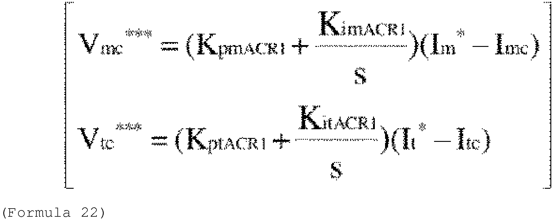
- PI proportional + integral control is performed so that the current detection values I mc and I tc of the respective components follow the current command values I m * and I t *, and the voltage command values V mc *** and V tc *** of the m-axis and the t-axis are output.
- V mc ⁇ ⁇ ⁇ K pmACR 1 + K imACR 1 s I m ⁇ ⁇ I mc
- V tc ⁇ ⁇ ⁇ K ptACR 1 + K itACR 1 s I t ⁇ ⁇ I tc
- K pmACR represents the m-axis current control proportional gain
- K imACR represents the m-axis current control integral gain
- K ptACR represents the t-axis current control proportional gain
- K itACR represents the t-axis current control integral gain
- a coordinate conversion unit 16' outputs a three-phase AC voltage command values V u *, V v *, V w * from the voltage command values V mc ***, V tc ***, and the phase estimation value ⁇ dc .
- current control may be calculated on the m-t axis, and high response current control characteristics can be obtained with low sensitivity to the primary resistance value.
- FIG. 9 is a configuration diagram of a power converter in the fifth embodiment.
- the configuration shown in FIG. 9 is the same as that shown in FIG. 1 except for the speed estimation calculation unit 5 and 26, and therefore, the description thereof is omitted.
- 26 is a level value for determining a low speed range and a middle-high speed range, with two ( ⁇ * 1 , ⁇ * 2 ) being set.
- 5% of the rated frequency is set to ⁇ * 1
- 10% of the rated frequency is set to ⁇ * 2 .
- the level value for determination is set to the first ⁇ * 1 and actual operation is performed.
- the level value for determination is changed to the second ⁇ * 2 at a next calculation timing.
- level values for determination are set in the fifth embodiment, a plurality of level values for determination may be prepared. In this way, by providing a plurality of level values for determination, highly accurate speed control can be obtained even in an induction motor having a large primary resistance value and a large influence of the variation.
- FIG. 10 is a configuration diagram of an induction motor driving system in the sixth embodiment.
- 27a constituted by the components 1, 4, 5"', 6 to 20, and 26 is the same as that of FIG. 9 .
- the induction motor 1 is driven by the power conversion device 27. Further, in the power conversion device 27, the components 1, 4, 5"', 6 to 20, and 26 are implemented as software as 27a, and a digital operator 27b is implemented as hardware.
- the level value 26 for determining the low speed range and the middle-high speed range may be set by a host device such as the digital operator 27b of the power conversion device 27, a personal computer 28, a tablet 29, and a smartphone 30. Further, by using a circuit constant, a rated frequency, and a rated current value of the induction motor set in an internal memory of a microcomputer mounted in the power conversion device including a power converter, the setting may be performed automatically.
- the voltage correction values ⁇ V d * and ⁇ V q * are generated based on the current command values I d * and I q * and the current detection values I dc and I qc , and the calculation is performed according to Formula (3) by adding the voltage correction value and the voltage reference value of the vector control.
- the vector control method may be performed in which intermediate current command values I d ** and I q ** shown in Formula (23) used for vector control calculation are generated based on the current command values I d * and I q * and the current detection values I dc and I qc , and the voltage command values V dc *** and V qc *** are calculated according to Formula (24) by using the current command value, the output frequency value ⁇ 1 *, and the circuit constants of the induction motor 1.
- K pdACR1 represents the d-axis current control proportional gain
- K idACR1 represents the d-axis current control integral gain
- K pqACR1 represents the q-axis current control integral gain
- K iqACR1 represents the q-axis current control integral gain
- T d represents d-axis electric time constant (L d /R)
- T q represents q-axis electric time constant (L q /R).
- the speed estimation calculation unit calculates the speed estimation value.
- K pqACR2 represents current control proportional gain
- K iqACR2 represents current control integral gain
- the outputs of the current control calculation unit of the m-t axes are output as V mc *** and V tc *** according to Formula (22).
- the speed estimation value is calculated in the speed estimation calculation unit 5", a method in which the current control and the speed estimation are used in combination in the t-axis current control may be used. That is, the speed estimation value ⁇ r ⁇ is calculated according to Formula (30).
- K ptACR2 represents current control proportional gain
- K itACR2 represents current control integral gain
- the speed estimation value may be calculated on the m-t axes in the low speed range and on the conventional d-q axes in the middle-high speed range.
- the switching element constituting the power converter 2 may be a silicon (Si) semiconductor element, or may be a wide band gap semiconductor element such as silicon carbide (SiC) or gallium nitride (GaN).
- the invention is not limited to the embodiments described above, and includes various modifications. For example, it is possible to replace a part of the configuration of one embodiment with the configuration of another embodiment, and it is also possible to add the configuration of another embodiment to the configuration of one embodiment. Further, it is also possible to add, delete, and replace other configurations for a part of the configurations of each embodiment.
Landscapes
- Engineering & Computer Science (AREA)
- Power Engineering (AREA)
- Control Of Ac Motors In General (AREA)
- Inverter Devices (AREA)
Abstract
Description
- The present invention relates to a speed sensorless vector control of an induction motor that does not use a speed sensor, and relates to an induction motor speed estimation method and a power conversion device using the induction motor speed estimation method.
- There is so-called speed sensorless vector control that estimates a speed of an induction motor without providing a speed sensor and controls the speed of the induction motor on the basis of a speed estimation value.
JP-A-6-105580 Patent Literature 1, a disturbance observer is provided to estimate a q-axis back electromotive force value, and to calculate a speed estimation value ωr^ by dividing by a magnetic flux coefficient according to the following Formula (1).
- Here, R1 represents a primary resistance value, R2' represents a secondary resistance value converted to a primary side, Lσ represents a leakage inductance value, M represents a mutual inductance value, L2 represents a secondary inductance value, and Tobs represents a speed estimation delay time constant set in the disturbance observer.
- In this method, when the primary resistance value R1 changes with coil temperature inside the induction motor, an error may occur between a set value R1* and the primary resistance value R1 used in Formula (1). In this case, an estimation error is generated in the speed estimation value, and therefore, stable speed control cannot be performed and torque shortage occurs in a low speed range where an output voltage becomes low.
- Therefore, as a control method with low sensitivity to changes in primary resistance value, a technique is described in which circuit constants of the induction motor other than the primary resistance value are assumed as true values, a γ-axis which is a primary current estimation error vector direction caused by a new primary resistance setting error and a δ-axis ahead of the γ-axis by 90 degrees are defined, and torque shortage is prevented by estimating a rotating speed on the control axes as described in
JP-A-2005-057963 -
- PTL 1:
JP-A-6-105580 - PTL 2:
JP-A-2005-057963 - In the method described in
Patent Literature 2, as described in <4> ofclaim 4 ofPatent Literature 2, the formula is derived by setting constants other than the primary resistance value as true values, as described in <5> of theclaim 4, a vector direction of a current estimation error ee iRs in consideration of only the setting error of the primary resistance value is calculated from the formula, and if there is an error other than the primary resistance value, the characteristics of the speed sensorless vector control may also be deteriorated. - A purpose of the present invention is to provide a speed estimation method capable of preventing torque shortage caused by the coil temperature inside the induction motor and obtaining highly accurate speed control characteristics and to provide a power conversion device using the speed estimation method.
- In view of the above background and problems, the invention provides a power conversion device that drives an induction motor by speed sensorless vector control, which includes a coordinate conversion unit that converts a command value or a detection value to control axes using a primary current direction and a direction delayed by 90 degrees from the primary current direction as a rotating coordinate system; and a speed estimation calculation unit that calculates a speed estimation value of the induction motor on the basis of the command value or the detection value converted by the coordinate conversion unit. The power conversion device controls an output frequency value on the basis of the speed estimation value.
- According to the invention, it is possible to provide a speed estimation method capable of preventing torque shortage caused by the coil temperature inside the induction motor and obtaining highly accurate speed control characteristics and a power conversion device using the speed estimation method.
-
- [
FIG. 1] FIG. 1 is a configuration diagram of a power conversion device in a first embodiment. - [
FIG. 2] FIG. 2 is a diagram of a load operation characteristic when using related art. - [
FIG. 3] FIG. 3 is a d-q axes vector diagram in related art. - [
FIG. 4] FIG. 4 is an m-t axes vector diagram in the first embodiment. - [
FIG. 5] FIG. 5 is a diagram of a load operation characteristic in the first embodiment. - [
FIG. 6] FIG. 6 is a configuration diagram illustrating a verification method when the first embodiment is employed. - [
FIG. 7] FIG. 7 is a configuration diagram of a speed estimation calculation unit in a third embodiment. - [
FIG. 8] FIG. 8 is a configuration diagram of a power conversion device in a fourth embodiment. - [
FIG. 9] FIG. 9 is a configuration diagram of a power conversion device in a fifth embodiment. - [
FIG. 10] FIG. 10 is a configuration diagram of an induction motor driving system in a sixth embodiment. - The embodiments will be described in detail below with reference to the drawings.
-
FIG. 1 is a configuration diagram of a power conversion device in the first embodiment. InFIG. 1 , aninduction motor 1 driven by the power conversion device is configured to generate torque by a magnetic flux generated by a current of a magnetic flux axis component (d-axis) and a current of a torque axis component (q-axis) orthogonal to the magnetic flux axis. Apower converter 2 is configured to output a voltage value proportional to three-phase alternating current (AC) voltage command values Vu*, Vv*, Vw*, and to vary an output voltage and an output frequency of theinduction motor 1. A direct current (DC)power supply 2a is configured to supply a DC voltage to thepower converter 2. Acurrent detector 3 is configured to output detection values Iuc, Ivc, and Iwc of three-phase AC currents Iu, Iv, and Iw of theinduction motor 1. Thecurrent detector 3 may detect phase currents of two phases of the three phases of theinduction motor 1, for example, a U-phase and a W-phase, and a line current of a V-phase is obtained as Iv = - (Iu + Iw) from an AC condition (Iu + Iv + Iw = 0). Acoordinate conversion unit 4 is configured to output current detection values Idc and Iqc of the d-axis and the q-axis from the detection values Iuc, Ivc, and Iwc of the three-phase AC currents Iu, Iv and Iw and a phase estimation value θdc. - A speed
estimation calculation unit 5 is configured to output a speed estimation value ωr^ of theinduction motor 1 on the basis of current command values Im*, It*, current detection values Imc, Itc, and voltage command values Vmc**, Vtc** of an m-axis and a t-axis, an output frequency value ω1* and circuit constants of the induction motor 1 (R1, R2', M, L2, ϕ2d*). - A slip frequency calculation unit 6 is configured to output a slip frequency command value ωs* of the
induction motor 1 on the basis of current command values Id* and Iq* of the d-axis and the q-axis and a secondary time constant T2 calculated from the circuit constants of theinduction motor 1. An addition unit 7 is configured to output an output frequency value ω1*, which is an addition value of the speed estimation value ωr^ and the slip frequency command value ωs*. - A phase
estimation calculation unit 8 is configured to integrate and calculate the output frequency value ω1* and to output the phase estimation value θdc. - A d-axis current
command setting unit 9 is configured to output a d-axis current command value Id* having a positive polarity. In a constant torque region, the d-axis current command value Id* is set or controlled to a constant value. In the constant output region, Id* is variably set or controlled with respect to the torque and a rotating speed. - A speed
control calculation unit 10 is configured to output a q-axis current command value Iq* from a deviation (ωr* - ωr^^) between the speed command value ωr* and a speed estimation value ωr^^. - A vector
control calculation unit 11 is configured to output voltage reference values Vdc* and Vqc* of the d-axis and the q-axis on the basis of the circuit constants of the induction motor 1 (R1, Lσ, M, L2) and the current command values Id*, Iq*, and the output frequency value ω1*. - A d-axis current
control calculation unit 12 is configured to output a d-axis voltage correction value ΔVd* from a deviation (Id* - Idc) between the d-axis current command value Id* and the current detection value Idc. - A q-axis current
control calculation unit 13 is configured to output a q-axis voltage correction value ΔVq* from a deviation (Iq* - Iqc) between the q-axis current command value Iq* and the current detection value Iqc. - An
addition unit 14 is configured to output a voltage command value Vdc**, which is an addition value of the d-axis voltage reference value Vdc* and the d-axis voltage correction value ΔVd*. Anaddition unit 15 is configured to output a voltage command value Vqc**, which is an addition value of the q-axis voltage reference value Vqc* and the q-axis voltage correction value ΔVq*. - A
coordinate conversion unit 16 is configured to output three-phase AC voltage command values Vu*, Vv*, and Vw* from the voltage command values Vdc**, Vqc** and the phase estimation value θdc. - A primary current
phase calculation unit 17 is configured to output a phase angle θϕc from the d-axis to the m-axis from the current command values Id* and Iq*. - A
coordinate conversion unit 18 is configured to output the voltage command values Vmc** and Vtc** on the m-t axes from the voltage command values Vdc** and Vqc** and the phase angle θϕc. - A
coordinate conversion unit 19 is configured to output current detection values Imc and Itc on the m-t axes from the current detection values Idc and Iqc of the d-axis and the q-axis. - A
coordinate conversion unit 20 is configured to output the current command values Im* and It* on the m-t axes from the d-axis current command value Id* and the q-axis current command value Iq*. - First, basic operations of the speed sensorless control method when the primary current
phase calculation unit 17 and thecoordinate conversion units 18 to 20 which are the characteristics of the first embodiment are not used will be described. - The d-axis current
command setting unit 9 outputs a current command value Id* necessary for generating a d-axis secondary magnetic flux value ϕ2d in theinduction motor 1. Further, in the speedcontrol calculation unit 10, the q-axis current command value Iq* is calculated according to Formula (2) so that the speed estimation value ωr^^ coincides with the speed command value ωr*.
- Here, KpASR represents speed control proportional gain, and KiASR represents speed control integral gain.
- The vector
control calculation unit 11 calculates the voltage reference values Vdc* and Vqc* according to Formula (3) using the current command values Id* and Iq* of the d-axis and the q-axis, the circuit constants of the induction motor 1 (R1, Lσ, M, L2), a d-axis secondary flux command value ϕ2d*, and the output frequency value ω1*.
- Here, TACR represents a time constant corresponding to a current control delay.
- The d-axis current command value Id* and the current detection value Idc are input to the d-axis current
control calculation unit 12, and the q-axis current command value Iq* and the current detection value Iqc are input to the q-axis currentcontrol calculation unit 13. Here, according to Formula (4), PI (proportional + integral) control is performed so that the current detection values Idc and Iqc of respective components follow the current command values Id* and Iq*, and the voltage correction values ΔVd* and ΔVq* of the d-axis and the q-axis are output.
- Here, KpdACR represents d-axis current control proportional gain, KidACR represents d-axis current control integral gain, KpqACR represents q-axis current control proportional gain, and KiqACR represents q-axis current control integral gain.
- In addition, in the
addition units

the voltage command values Vdc** and Vqc** are calculated, and the output voltage of thepower converter 2 is controlled. - The speed
estimation calculation unit 5 estimates the speed of theinduction motor 1 is by Formula (1). - In addition, the slip frequency calculation unit 6 calculates the slip frequency command value ωs* of the
induction motor 1 according to Formula (6).
- Here, T2 represents a secondary time constant value.
- Further, according to Formula (7),

the addition unit 7 calculates the output frequency value ω1* using the speed estimation value ωr^ and the slip frequency command value ωs*. - The phase
estimation calculation unit 8 calculates a phase θd of the magnetic flux axis of theinduction motor 1 according to Formula (8).
- The calculation by sensorless control is executed taking the phase estimation value θdc which is an estimation value of the phase θd of the magnetic flux axis as a control reference. The above are the basic operations.
- Here, control characteristics when using the primary current
phase calculation unit 17 and the coordinateconversion units 18 to 20 which are characteristics of the first embodiment will be described. -
FIG. 2 shows load operation characteristics when usingPatent Literature 1 which is a related art for speed estimation calculation. Here, setting of the primary resistance value R1* used in Formula (1) and Formula (3) is set to 0.5 times R1, theinduction motor 1 is operated at 1 Hz in a low speed range, and a ramp-shaped torque τL is given up to 200% from a point A to a point C in the figure. Although an actual speed value ωr of theinduction motor 1 is lower than the speed estimation value ωr^, and theinduction motor 1 is stopped after the point B shown inFIG. 2 , it can be seen that the speed estimation value ωr^ is 1 Hz in a steady state, and an estimation error Δωr is generated. This is due to a voltage component of (R1* + R2'*)Iqc included in the numerator term of Formula (1), and torque shortage may be generated in the low speed operation. - By using the primary current
phase calculation unit 17 and the coordinateconversion units 18 to 20 which are characteristics of the first embodiment, the torque shortage can be improved. This will be described below. -
FIG. 3 is a d-q axes vector diagram, which are control axes in the related art. A direction of the magnetic flux is d-axis, and a direction that is 90 degrees (π/2) ahead of the d-axis is q-axis. Here, a d-axis current Id, a q-axis current Iq, and a primary current I1 are in a relationship of Formula (9).
- Further, in Formula (10),

a relationship of a phase angle between Id and I1 is shown. -
FIG. 4 is an m-t axes vector diagram, which are control axes introduced in the first embodiment. A direction of the primary current is the t-axis, and a direction delayed by 90 degrees from the t-axis is the m-axis. Here, an m-axis current Im, a t-axis current It, and a primary current I1 are in a relationship of Formula (11).
- In the primary current
phase calculation unit 17 inFIG. 1 , the current command values Id*, Iq* of the d-axis and the q-axis are input, and according to Formula (12),

a phase angle θϕc used for the calculation formulas of the coordinateconversion units 18 to 20 is output. - In the coordinate
conversion unit 18, voltage command values Vdc** and Vqc** of the d-axis and the q-axis and the phase angle θϕc are input, and according to Formula (13),

voltage command values Vmc** and Vtc** of the m-axis and the t-axis are output. - In the coordinate
conversion unit 19, the current detection values Idc and Iqc of the d-axis and the q-axis and the phase angle θϕc are input, and according to Formula (14),

the current detection values Imc and Itc of the m-axis and the t-axis are output. - In the coordinate
conversion unit 20, the current command values Id*, Iq* of the d-axis and the q-axis, and the phase angle θϕc are input, and according to Formula (15),
- In the speed
estimation calculation unit 5, according to Formula (16), an m-axis back electromotive force value is estimated and divided by the magnetic flux coefficient, and ωr^^ is output.
- (R1* + R2'*)Imc, which is a voltage component included in a numerator term of Formula (16) in the low speed range, is always 0 V by setting Imc = 0 even if there is an error in setting R1*, and thus the estimation accuracy of the speed estimation value ωr^^ is improved.
-
FIG. 5 shows the load operation characteristics in the first embodiment (the conditions used inFIG. 2 are set). By comparing the load characteristics disclosed inFIGS. 2 and5 , the accuracy of the speed estimation value ωr^^ of theinduction motor 1 is significantly improved, and the effect thereof is obvious. That is, in a low speed range, sensitivity to the primary resistance value is low, and stable and highly accurate speed control can be obtained. - In addition, an absolute value of the primary frequency ω1* may be about 10% or less of a rated frequency of the
induction motor 1 in the low speed range described above. Alternatively, a drop voltage related to the primary resistance value and a drop voltage related to the back electromotive force are compared, and it is also possible to set a case where Formula (17)

is satisfied as the low speed range. - Here, a verification method when the first embodiment is employed will be described using
FIG. 6 . - When the control calculation is performed on the m-t axes of the primary current axes, an m-axis voltage command value is expressed by Formula (18).

- In the formula, since the m-axis current Im = 0, the m-axis voltage command value becomes Formula (19).

- The value of the primary resistance value R1 changes as a length of an electric wire connecting a
power conversion device 21 and theinduction motor 1 is changed. In the method of the first embodiment, since the sensitivity to the primary resistance value R1 is low, an m-axis voltage value Vm is a constant value. - Therefore, as shown in
FIG. 6 , avoltage detector 22 and acurrent detector 23 are attached to thepower conversion device 21 that drives theinduction motor 1, and anencoder 24 is attached to a shaft of theinduction motor 1. A three-phase voltage value (Vu1, Vv1, Vw1), which is an output of thevoltage detector 22, a three-phase current value (Iu1, Iv1, Iw1), which is an output of thecurrent detector 23, and a position θd1, which is an output of the encoder, are input to a Vm voltagecomponent calculation unit 25. The Vm voltage component is calculated based on the input information, and the first embodiment is employed as long as there is no change in an output value of the Vm voltagecomponent calculation unit 25 even if the length of the electric wire described above is changed. - As described above, the first embodiment is a power conversion device for driving an induction motor by speed sensorless vector control, which has a coordinate conversion unit for converting a command value or a detection value to control axes using a primary current direction and a direction delayed by 90 degrees from the primary current direction as a rotating coordinate system; and a speed estimation calculation unit for calculating a speed estimation value of the induction motor on the basis of the command value or the detection value converted by the coordinate conversion unit. The power conversion device controls an output frequency value on the basis of the speed estimation value. That is, the direction of the primary current is set as the t-axis and the direction delayed by 90 degrees therefrom is set as the m-axis, and the speed estimation value is calculated by using the voltage command values and the current detection values on the rotating coordinate system of the m-t axes, and the circuit constants of the induction motor.
- In this way, it is possible to provide an induction motor speed estimation method capable of obtaining highly accurate speed control characteristics without torque shortage by lowering sensitivity to the primary resistance value in the low speed range, and a power conversion device using the induction motor speed estimation method.
- The first embodiment is a method for improving the accuracy of the speed estimation value in the low speed range, in the second embodiment, a method for improving the accuracy of the speed estimation value in a middle-high speed range will be described.
- The configuration diagram of the power conversion device in the second embodiment is the same as that shown in
FIG. 1 except for the speedestimation calculation unit 5, therefore, the drawing and the description thereof are omitted. - According to Formula (20),

- ω1*Lσ*Im*, which is a voltage component included in a numerator term of Formula (20) in the middle-high speed range, is always 0 V by setting Im* = 0 even if there is an error in setting Lσ*, and thus the estimation accuracy of the speed estimation value ωr^^ is improved. That is, in the middle-high speed range, sensitivity to the leakage inductance value is low, and highly accurate speed control can be obtained.
- In the middle-high speed range described above, an absolute value of the primary frequency ω1* may be about 10% or more of a rated rotating speed. Alternatively, a drop voltage related to the primary resistance value and a drop voltage related to the back electromotive force are compared, it is also possible to set a case where Formula (21) is satisfied as the middle-high speed range.

- The first embodiment is a method for improving the accuracy of the speed estimation value in the low speed range, and in the third embodiment, a method for switching the speed estimation value in the low speed range and the middle-high speed range will be described.
- The configuration diagram of the power conversion device in the third embodiment is the same as that shown in
FIG. 1 except for the speedestimation calculation unit 5, therefore, the drawing and the description thereof are omitted. -
FIG. 7 shows a configuration of a speedestimation calculation unit 5" in the third embodiment. A speedestimation calculation unit 5"a is a calculation unit of Formula (16) and outputs a speed estimation value ωr^^, and 5"b is a calculation unit of Formula (20) and outputs a speed estimation value ωr^^^. 5"c is a switching unit for the speed estimation value, which selects the speed estimation value ωr^^ in the low speed range and selects the speed estimation value ωr^^^ in the middle-high speed range, and outputs either one of them as ωr^^^^. - Further, for the low speed range and the middle-high speed range described above, the low speed range may be set when an absolute value of the primary frequency ω1* is about 10% or less of a rated rotating speed, and the middle-high speed range may be set when the absolute value of the primary frequency ω1* is about 10% or more of the rated rotating speed. Alternatively, a drop voltage related to the primary resistance value and a drop voltage related to the back electromotive force are compared, it is also possible to set the case where Formula (17) is satisfied as the low speed range and the case where Formula (21) is satisfied as the middle-high speed range.
- As in the third embodiment, by switching the speed estimation value in the low speed range and the high speed range, highly accurate speed control in the entire speed range can be obtained.
- In the first embodiment, only the speed estimation calculation unit is calculated on the m-t axes. However, in the fourth embodiment, a method in which the current control calculation units of d-axis and q-axis are also calculated on the m-t axes will be described.
-
FIG. 8 is a configuration diagram of the power conversion device in the fourth embodiment. Since 1 to 4, 6 to 10, 17, 19, and 20 inFIG. 8 are the same as those inFIG. 1 , descriptions thereof will be omitted. - In
FIG. 8 , an m-axis current control calculation unit 12' outputs an m-axis voltage command value Vmc*** from a deviation (Im* - Imc) between the m-axis current command value Im* and the current detection value Imc. A t-axis current control calculation unit 13' outputs a t-axis voltage command value Vtc*** from a deviation (It* - Itc) between the t-axis current command value It* and the current detection value Itc. - Here, according to Formula (22), PI (proportional + integral) control is performed so that the current detection values Imc and Itc of the respective components follow the current command values Im* and It*, and the voltage command values Vmc*** and Vtc*** of the m-axis and the t-axis are output.
- Here, KpmACR represents the m-axis current control proportional gain, KimACR represents the m-axis current control integral gain, KptACR represents the t-axis current control proportional gain, and KitACR represents the t-axis current control integral gain.
- A coordinate conversion unit 16' outputs a three-phase AC voltage command values Vu*, Vv*, Vw* from the voltage command values Vmc***, Vtc***, and the phase estimation value θdc.
- As in the fourth embodiment, current control may be calculated on the m-t axis, and high response current control characteristics can be obtained with low sensitivity to the primary resistance value.
- In the first to fourth embodiments, in the speed
estimation calculation units -
FIG. 9 is a configuration diagram of a power converter in the fifth embodiment. The configuration shown inFIG. 9 is the same as that shown inFIG. 1 except for the speedestimation calculation unit - 26 is a level value for determining a low speed range and a middle-high speed range, with two (ω*1, ω*2) being set.
- For example, 5% of the rated frequency is set to ω*1, and 10% of the rated frequency is set to ω*2. Then, in a speed
estimation calculation unit 5"', firstly, the level value for determination is set to the first ω*1 and actual operation is performed. As a result, when torque shortage or overcurrent trip is generated, the level value for determination is changed to the second ω*2 at a next calculation timing. With this configuration, it is possible to optimally set the level value for determination. - Further, although two level values for determination are set in the fifth embodiment, a plurality of level values for determination may be prepared. In this way, by providing a plurality of level values for determination, highly accurate speed control can be obtained even in an induction motor having a large primary resistance value and a large influence of the variation.
- In the sixth embodiment, an example in which the fifth embodiment is applied to an induction motor driving system will be described.
-
FIG. 10 is a configuration diagram of an induction motor driving system in the sixth embodiment. InFIG. 10 , 27a constituted by thecomponents FIG. 9 . - In
FIG. 10 , theinduction motor 1 is driven by the power conversion device 27. Further, in the power conversion device 27, thecomponents digital operator 27b is implemented as hardware. - The
level value 26 for determining the low speed range and the middle-high speed range may be set by a host device such as thedigital operator 27b of the power conversion device 27, apersonal computer 28, atablet 29, and a smartphone 30. Further, by using a circuit constant, a rated frequency, and a rated current value of the induction motor set in an internal memory of a microcomputer mounted in the power conversion device including a power converter, the setting may be performed automatically. - When the sixth embodiment is applied to an induction motor driving system, highly accurate speed control characteristics can be obtained in the entire speed range.
- Note that, in the sixth embodiment, although an example in which the fifth embodiment is applied has been described, the first to fourth embodiments may also be applied.
- Further, in the first to third embodiments, the voltage correction values ΔVd* and ΔVq* are generated based on the current command values Id* and Iq* and the current detection values Idc and Iqc, and the calculation is performed according to Formula (3) by adding the voltage correction value and the voltage reference value of the vector control. The vector control method may be performed in which intermediate current command values Id** and Iq** shown in Formula (23) used for vector control calculation are generated based on the current command values Id* and Iq* and the current detection values Idc and Iqc,

induction motor 1.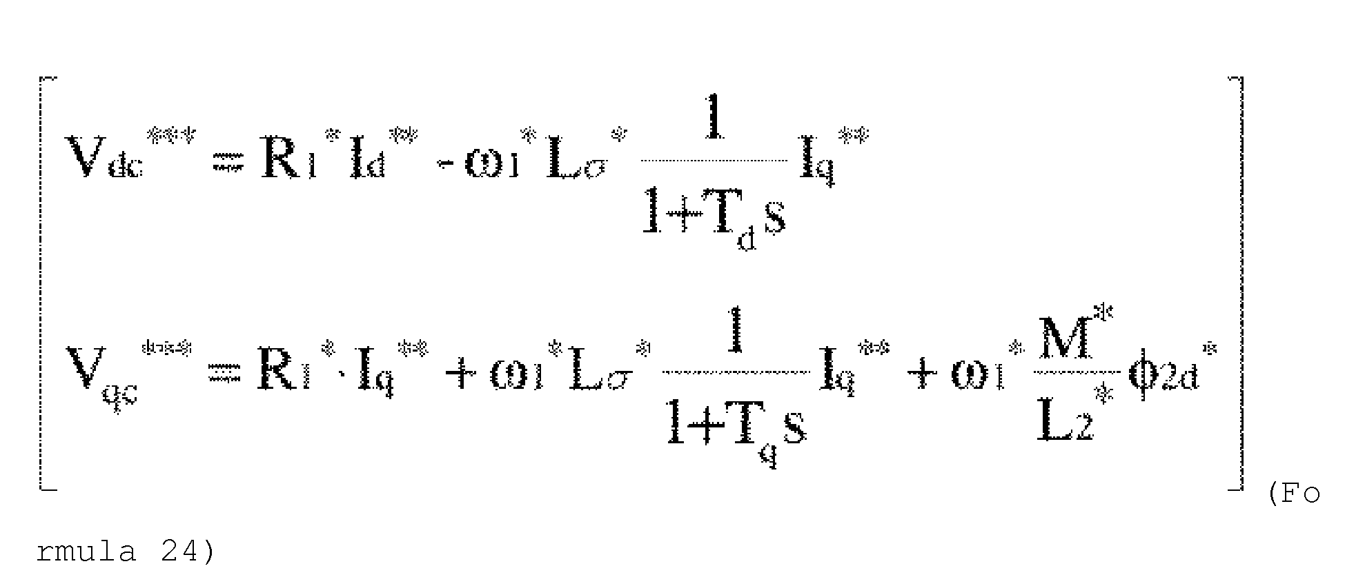
- Here, KpdACR1 represents the d-axis current control proportional gain, KidACR1 represents the d-axis current control integral gain, KpqACR1 represents the q-axis current control integral gain, KiqACR1 represents the q-axis current control integral gain, Td represents d-axis electric time constant (Ld/R), and Tq represents q-axis electric time constant (Lq/R).
- Further, the vector control method may also be performed in which based on the current detection values Idc and Iqc, and the current command values Id* and Iq*, a voltage correction value ΔVd_P* of a d-axis proportional calculation component, a voltage correction value ΔVd_i* of a d-axis integral calculation component, a voltage correction value ΔVq_p* of a q-axis proportional calculation component, and a voltage correction value ΔVq_i* of a q-axis integral calculation component, which are used for vector control calculation are calculated according to Formula (25),

induction motor 1, according to Formula (26),

the voltage command values Vdc**** and Vqc**** are calculated. - Further, in the first to sixth embodiments, the speed estimation calculation unit calculates the speed estimation value. However, a method in which current control and speed estimation are used in combination in q-axis current control may be used. That is, as shown in Formula (27), the speed estimation value ωr^^^^^ is calculated.

- Here, KpqACR2 represents current control proportional gain, and KiqACR2 represents current control integral gain.
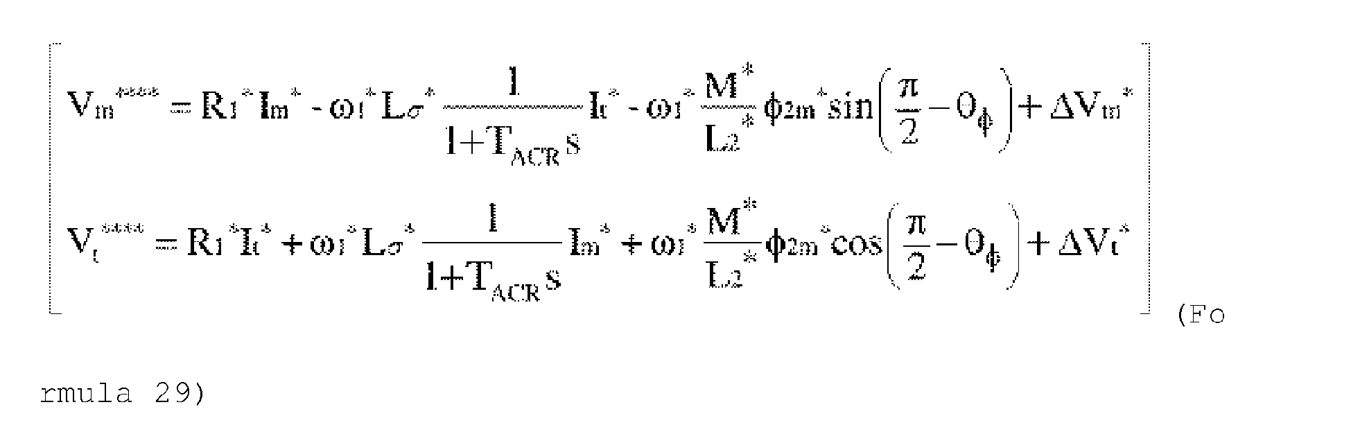
- Further, in the fourth embodiment, the outputs of the current control calculation unit of the m-t axes are output as Vmc*** and Vtc*** according to Formula (22). However, voltage correction values ΔVm* and ΔVt* are generated based on the current command values Im* and Im* and the current detection values Imc and Imc according to Formula (28), and the voltage correction values and the voltage reference value of vector control are added according to Formula (29),

- In addition, in the fourth embodiment, although the speed estimation value is calculated in the speed
estimation calculation unit 5", a method in which the current control and the speed estimation are used in combination in the t-axis current control may be used. That is, the speed estimation value ωr^^^^^^ is calculated according to Formula (30).
- Here, KptACR2 represents current control proportional gain, and KitACR2 represents current control integral gain.
- Further, in the first to sixth embodiment, the speed estimation value may be calculated on the m-t axes in the low speed range and on the conventional d-q axes in the middle-high speed range.
- Note that, in the first to sixth embodiment, the switching element constituting the
power converter 2 may be a silicon (Si) semiconductor element, or may be a wide band gap semiconductor element such as silicon carbide (SiC) or gallium nitride (GaN). - Although the above embodiments have been described, the invention is not limited to the embodiments described above, and includes various modifications. For example, it is possible to replace a part of the configuration of one embodiment with the configuration of another embodiment, and it is also possible to add the configuration of another embodiment to the configuration of one embodiment. Further, it is also possible to add, delete, and replace other configurations for a part of the configurations of each embodiment.
-
- 1 induction motor
- 2 power converter
- 2a DC power supply
- 3 current detector
- 4, 16, 18, 19, 20 coordinate conversion unit
- 5 speed estimation calculation unit
- 6 slip frequency calculation unit
- 7 addition unit
- 8 phase estimation calculation unit
- 9 d-axis current command setting unit
- 10 speed control calculation unit
- 11 vector control calculation unit
- 12 d-axis current control calculation unit
- 13 q-axis current control calculation unit
- 14, 15 addition unit
- 17 primary current phase calculation unit
- 21 power conversion device
- 22 voltage detector
- 23 current detector
- 24 encoder
- 25 Vm voltage component calculation unit
- 26 level value
- 27 power conversion device
- 27a soft processing
- 27b digital operator
- Id* d-axis current command value
- Iq* q-axis current command value
- Idc d-axis current detection value
- Iq* q-axis current detection value
- Im* m-axis current command value
- It* t-axis current command value
- Imc m-axis current detection value
- Itc t-axis current detection value
- ωr* speed command value
- ωr speed of
induction motor 1 - ωr^, ωr^^, ωr^^^, ωr^^^^, ωr^^^^^, ωr^^^^^^, speed estimation value
- ωs* slip frequency command value
- ω1* output frequency value or speed command value of
induction motor 1 - θdc phase estimation value
- θϕ, θϕc phase angle
- Vdc* d-axis voltage command reference value
- Vqc* q-axis voltage command reference value
- Vdc**, Vdc***, Vdc****, Vdc***** d-axis voltage command value
- Vqc**, Vqc***, Vqc****, Vqc***** q-axis voltage command value
- Vmc**, Vmc***, Vmc**** m-axis voltage command value
- Vtc**, Vtc***, Vtc**** t-axis voltage command value
Claims (15)
- A power conversion device that drives an induction motor by speed sensorless vector control, comprising:a coordinate conversion unit configured to convert a command value or a detection value to control axes using a primary current direction and a direction delayed by 90 degrees from the primary current direction as a rotating coordinate system; anda speed estimation calculation unit configured to calculate a speed estimation value of the induction motor on the basis of the command value or the detection value converted by the coordinate conversion unit, whereinan output frequency value is controlled on the basis of the speed estimation value.
- The power conversion device according to claim 1, further comprising:
a vector control calculation unit configured to perform vector control calculation on the basis of the command value or the detection value converted by the coordinate conversion unit. - The power conversion device according to claim 1 or 2, wherein
the coordinate conversion unit is configured to calculate current command values or current detection values and voltage command values of a t-axis which is the primary current direction and of a m-axis which is a direction delayed by 90 degrees from the t-axis by using a sine signal and a cosine signal of a subtraction value obtained by dividing a q-axis current command value or current detection value of the induction motor by a d-axis current command value or current detection value and subtracting an inverse tangent signal of the divided value from 90 degrees, and the current command values or current detection values and voltage command values of the d-axis and the q-axis. - The power conversion device according to claim 3, wherein a t-axis current command value or current detection value is a square root of an addition value of a value obtained by squaring the d-axis current command value or current detection value and a value obtained by squaring the q-axis current command value or current detection value, and the m-axis current command value or current detection value is zero.
- The power conversion device according to claim 3 or 4, wherein
the speed estimation calculation unit is configured to calculate the speed estimation value of the induction motor by using the m-axis voltage command value, the current command values and current detection values of the m-axis and the t-axis, a sine signal, a circuit constant of the induction motor, the output frequency value, and a slip frequency command value in a low speed range in which an absolute value of a value obtained by multiplying an addition value, which is obtained by adding a value obtained by multiplying a leakage inductance value of the induction motor by a d-axis current and a value obtained by dividing a mutual inductance by a secondary inductance and multiplying by a d-axis secondary flux, by the output frequency value or a speed command value, is smaller than an absolute value of a value obtained by multiplying a primary resistance value by a q-axis current. - The power conversion device according to claim 3 or 4, wherein
the speed estimation calculation unit is configured to calculate the speed estimation value of the induction motor by using the t-axis voltage command value, the current command values and current detection values of the m-axis and the t-axis, a cosine signal, a circuit constant of the induction motor, the output frequency value, and a slip frequency command value in a middle-high speed range in which an absolute value of a value obtained by multiplying an addition value, which is obtained by adding a value obtained by multiplying a leakage inductance value of the induction motor by a d-axis current and a value obtained by dividing a mutual inductance by a secondary inductance and multiplying by a d-axis secondary flux, by the output frequency value or a speed command value, is larger than an absolute value of a value obtained by multiplying a primary resistance value by a q-axis current. - The power conversion device according to claim 3 or 4, wherein
the speed estimation calculation unit is configured to switch the speed estimation value of the induction motor between a low speed range in which an absolute value 1 of a value obtained by multiplying an addition value, which is obtained by adding a value obtained by multiplying a leakage inductance value of the induction motor by a d-axis current and a value obtained by dividing a mutual inductance by a secondary inductance and multiplying by a d-axis secondary flux, by the output frequency value or a speed command value, is smaller than an absolute value 2 of a value obtained by multiplying a primary resistance value by a q-axis current, and a middle-high speed range in which the absolute value 1 is larger than the absolute value 2. - The power conversion device according to claim 7, wherein
a level value that switches between the low speed range and the middle-high speed range is automatically set by using a circuit constant of the induction motor and a rated frequency and a rated current value set in internal memory. - The power conversion device according to claim 7, wherein
a switching threshold of the low speed range and the middle-high speed range can be set and changed by connecting a digital operator or a personal computer or tablet or a smartphone device. - A speed estimation method for speed sensorless vector control of an induction motor, the speed estimation method comprising:
calculating a speed estimation value of the induction motor on control axes which use a primary current direction and a direction delayed by 90 degrees from the primary current direction as the control axes of a rotating coordinate system. - The speed estimation method according to claim 10, further comprising:
a coordinate conversion processing that converts a command value or a detection value to the control axes, in which current command values or current detection values and voltage command values of a t-axis which is a primary current direction and a m-axis which is a direction delayed by 90 degrees from the t-axis are calculated by using a sine signal and a cosine signal of a subtraction value obtained by dividing a q-axis current command value or current detection value of the induction motor by a d-axis current command value or current detection value and subtracting an inverse tangent signal of the divided value from 90 degrees, and the current command values or current detection values and voltage command values of the d-axis and the q-axis. - The speed estimation method according to claim 11, wherein
a t-axis current command value or current detection value is a square root of an addition value of a value obtained by squaring the d-axis current command value or current detection value and a value obtained by squaring the q-axis current command value or current detection value, and the m-axis current command value or current detection value is zero. - The speed estimation method according to claim 11 or 12, wherein
the speed estimation value is calculated by using the m-axis voltage command value, the current command values and current detection values of the m-axis and the t-axis, a sine signal, a circuit constant of the induction motor, the output frequency value, and a slip frequency command value in a low speed range in which an absolute value of a value obtained by multiplying an addition value, which is obtained by adding a value obtained by multiplying a leakage inductance value of the induction motor by a d-axis current and a value obtained by dividing a mutual inductance by a secondary inductance and multiplying by a d-axis secondary flux, by the output frequency value or a speed command value, is smaller than an absolute value of a value obtained by multiplying a primary resistance value by a q-axis current. - The speed estimation method according to claim 11 or 12, wherein
the speed estimation value is calculated by using the t-axis voltage command value, the current command values and current detection values of the m-axis and the t-axis, a cosine signal, a circuit constant of the induction motor, the output frequency value, and a slip frequency command value in a middle-high speed range in which an absolute value of a value obtained by multiplying an addition value, which is obtained by adding a value obtained by multiplying a leakage inductance value of the induction motor by a d-axis current and a value obtained by dividing a mutual inductance by a secondary inductance and multiplying by a d-axis secondary flux, by the output frequency value or a speed command value, is larger than an absolute value of a value obtained by multiplying a primary resistance value by a q-axis current. - The speed estimation method according to claim 11 or 12, wherein
the speed estimation value is switched between a low speed range in which an absolute value 1 of a value obtained by multiplying an addition value, which is obtained by adding a value obtained by multiplying a leakage inductance value of the induction motor by a d-axis current and a value obtained by dividing a mutual inductance by a secondary inductance and multiplying by a d-axis secondary flux, by the output frequency value or a speed command value, is smaller than an absolute value 2 of a value obtained by multiplying a primary resistance value by a q-axis current, and a middle-high speed range in which the absolute value 1 is larger than the absolute value 2.
Applications Claiming Priority (2)
| Application Number | Priority Date | Filing Date | Title |
|---|---|---|---|
| JP2017083412A JP6979281B2 (en) | 2017-04-20 | 2017-04-20 | Induction motor speed estimation method and power conversion device using it |
| PCT/JP2018/005238 WO2018193697A1 (en) | 2017-04-20 | 2018-02-15 | Induction motor speed estimation method and power conversion device using same |
Publications (3)
| Publication Number | Publication Date |
|---|---|
| EP3614559A1 true EP3614559A1 (en) | 2020-02-26 |
| EP3614559A4 EP3614559A4 (en) | 2020-12-30 |
| EP3614559B1 EP3614559B1 (en) | 2023-06-28 |
Family
ID=63857005
Family Applications (1)
| Application Number | Title | Priority Date | Filing Date |
|---|---|---|---|
| EP18787754.3A Active EP3614559B1 (en) | 2017-04-20 | 2018-02-15 | Induction motor speed estimation method and power conversion device using same |
Country Status (5)
| Country | Link |
|---|---|
| EP (1) | EP3614559B1 (en) |
| JP (1) | JP6979281B2 (en) |
| CN (1) | CN110235355B (en) |
| ES (1) | ES2949631T3 (en) |
| WO (1) | WO2018193697A1 (en) |
Families Citing this family (5)
| Publication number | Priority date | Publication date | Assignee | Title |
|---|---|---|---|---|
| US11159112B2 (en) | 2018-11-30 | 2021-10-26 | The Trustees Of Columbia University In The City Of New York | Systems and methods for high performance filtering techniques for sensorless direct position and speed estimation |
| JP7286528B2 (en) * | 2019-12-13 | 2023-06-05 | 株式会社日立産機システム | power converter |
| JP7627204B2 (en) * | 2021-11-18 | 2025-02-05 | 株式会社日立産機システム | Power Conversion Equipment |
| JP7628071B2 (en) | 2021-12-01 | 2025-02-07 | 株式会社日立産機システム | Power Conversion Equipment |
| JP7850059B2 (en) | 2022-11-24 | 2026-04-22 | 株式会社日立産機システム | Power converter and motor control system |
Family Cites Families (8)
| Publication number | Priority date | Publication date | Assignee | Title |
|---|---|---|---|---|
| JP2943377B2 (en) * | 1991-04-01 | 1999-08-30 | 株式会社明電舎 | Vector controller for induction motor |
| JP3160778B2 (en) | 1992-09-18 | 2001-04-25 | 株式会社日立製作所 | Inverter-driven motor speed estimation method and device, and motor vector control device using the speed estimation method |
| JPH06209590A (en) * | 1993-01-11 | 1994-07-26 | Meidensha Corp | Vector controller for induction motor |
| KR100400594B1 (en) * | 2001-04-24 | 2003-10-08 | 엘지산전 주식회사 | Apparatus for speed presumption of induction motor |
| JP4281054B2 (en) * | 2003-08-07 | 2009-06-17 | 学校法人明治大学 | Speed sensorless vector control method and apparatus for induction motor |
| JP5130031B2 (en) * | 2007-12-10 | 2013-01-30 | 株式会社日立製作所 | Position sensorless control device for permanent magnet motor |
| JP2009165281A (en) * | 2008-01-08 | 2009-07-23 | Fuji Electric Systems Co Ltd | Speed sensorless vector controller |
| JP6431788B2 (en) * | 2015-03-05 | 2018-11-28 | 株式会社日立産機システム | Power converter and control method thereof |
-
2017
- 2017-04-20 JP JP2017083412A patent/JP6979281B2/en active Active
-
2018
- 2018-02-15 CN CN201880009903.2A patent/CN110235355B/en active Active
- 2018-02-15 WO PCT/JP2018/005238 patent/WO2018193697A1/en not_active Ceased
- 2018-02-15 EP EP18787754.3A patent/EP3614559B1/en active Active
- 2018-02-15 ES ES18787754T patent/ES2949631T3/en active Active
Also Published As
| Publication number | Publication date |
|---|---|
| WO2018193697A1 (en) | 2018-10-25 |
| CN110235355B (en) | 2023-03-10 |
| JP6979281B2 (en) | 2021-12-08 |
| JP2018182989A (en) | 2018-11-15 |
| ES2949631T3 (en) | 2023-10-02 |
| EP3614559A4 (en) | 2020-12-30 |
| CN110235355A (en) | 2019-09-13 |
| EP3614559B1 (en) | 2023-06-28 |
Similar Documents
| Publication | Publication Date | Title |
|---|---|---|
| KR101109067B1 (en) | Position sensorless control device of permanent magnet motor | |
| EP3614559B1 (en) | Induction motor speed estimation method and power conversion device using same | |
| US8988027B2 (en) | Motor control apparatus and motor control method | |
| KR100371369B1 (en) | Vector control system of induction motor | |
| EP3267577B1 (en) | Power conversion device and method for controlling same | |
| JP5223109B2 (en) | Control device for permanent magnet type synchronous motor | |
| KR101619567B1 (en) | Apparatus for estimating parameters in induction machine | |
| US11437944B2 (en) | Power conversion device | |
| EP3886314A1 (en) | Inverter control device | |
| EP3605830B1 (en) | Synchronous motor control apparatus | |
| JP5499594B2 (en) | Control device for permanent magnet type synchronous motor | |
| JP6641445B2 (en) | Power converter control method and power converter | |
| EP3703249B1 (en) | Power conversion device and controlling method therefor | |
| JP6848680B2 (en) | Synchronous motor control device | |
| JP5534991B2 (en) | Control device for synchronous motor | |
| JP2009284557A (en) | Controller for permanent magnet type synchronous motor | |
| JP6573213B2 (en) | Control device for permanent magnet type synchronous motor | |
| JP6108114B2 (en) | Control device for permanent magnet type synchronous motor | |
| EP4625809A1 (en) | Power conversion device and motor control system | |
| JP2020058231A (en) | Power converter control method and power converter | |
| JP5040605B2 (en) | Control device for permanent magnet type synchronous motor |
Legal Events
| Date | Code | Title | Description |
|---|---|---|---|
| STAA | Information on the status of an ep patent application or granted ep patent |
Free format text: STATUS: THE INTERNATIONAL PUBLICATION HAS BEEN MADE |
|
| PUAI | Public reference made under article 153(3) epc to a published international application that has entered the european phase |
Free format text: ORIGINAL CODE: 0009012 |
|
| STAA | Information on the status of an ep patent application or granted ep patent |
Free format text: STATUS: REQUEST FOR EXAMINATION WAS MADE |
|
| 17P | Request for examination filed |
Effective date: 20190705 |
|
| AK | Designated contracting states |
Kind code of ref document: A1 Designated state(s): AL AT BE BG CH CY CZ DE DK EE ES FI FR GB GR HR HU IE IS IT LI LT LU LV MC MK MT NL NO PL PT RO RS SE SI SK SM TR |
|
| AX | Request for extension of the european patent |
Extension state: BA ME |
|
| DAV | Request for validation of the european patent (deleted) | ||
| DAX | Request for extension of the european patent (deleted) | ||
| A4 | Supplementary search report drawn up and despatched |
Effective date: 20201130 |
|
| RIC1 | Information provided on ipc code assigned before grant |
Ipc: H02P 21/24 20160101AFI20201124BHEP Ipc: H02M 7/48 20070101ALI20201124BHEP |
|
| RIN1 | Information on inventor provided before grant (corrected) |
Inventor name: KANEKO, SATORU Inventor name: TOBARI, KAZUAKI Inventor name: SUGIMOTO, TAKUYA Inventor name: IWAJI, YOSHITAKA Inventor name: OOHASHI, HIRONORI Inventor name: NAKAMURA, ATSUHIKO Inventor name: ONUMA, YUSAKU |
|
| STAA | Information on the status of an ep patent application or granted ep patent |
Free format text: STATUS: EXAMINATION IS IN PROGRESS |
|
| 17Q | First examination report despatched |
Effective date: 20220307 |
|
| GRAP | Despatch of communication of intention to grant a patent |
Free format text: ORIGINAL CODE: EPIDOSNIGR1 |
|
| STAA | Information on the status of an ep patent application or granted ep patent |
Free format text: STATUS: GRANT OF PATENT IS INTENDED |
|
| INTG | Intention to grant announced |
Effective date: 20230208 |
|
| GRAS | Grant fee paid |
Free format text: ORIGINAL CODE: EPIDOSNIGR3 |
|
| GRAA | (expected) grant |
Free format text: ORIGINAL CODE: 0009210 |
|
| STAA | Information on the status of an ep patent application or granted ep patent |
Free format text: STATUS: THE PATENT HAS BEEN GRANTED |
|
| AK | Designated contracting states |
Kind code of ref document: B1 Designated state(s): AL AT BE BG CH CY CZ DE DK EE ES FI FR GB GR HR HU IE IS IT LI LT LU LV MC MK MT NL NO PL PT RO RS SE SI SK SM TR |
|
| REG | Reference to a national code |
Ref country code: CH Ref legal event code: EP |
|
| REG | Reference to a national code |
Ref country code: AT Ref legal event code: REF Ref document number: 1583631 Country of ref document: AT Kind code of ref document: T Effective date: 20230715 |
|
| REG | Reference to a national code |
Ref country code: IE Ref legal event code: FG4D |
|
| REG | Reference to a national code |
Ref country code: DE Ref legal event code: R096 Ref document number: 602018052501 Country of ref document: DE |
|
| REG | Reference to a national code |
Ref country code: ES Ref legal event code: FG2A Ref document number: 2949631 Country of ref document: ES Kind code of ref document: T3 Effective date: 20231002 |
|
| REG | Reference to a national code |
Ref country code: LT Ref legal event code: MG9D |
|
| PG25 | Lapsed in a contracting state [announced via postgrant information from national office to epo] |
Ref country code: SE Free format text: LAPSE BECAUSE OF FAILURE TO SUBMIT A TRANSLATION OF THE DESCRIPTION OR TO PAY THE FEE WITHIN THE PRESCRIBED TIME-LIMIT Effective date: 20230628 Ref country code: NO Free format text: LAPSE BECAUSE OF FAILURE TO SUBMIT A TRANSLATION OF THE DESCRIPTION OR TO PAY THE FEE WITHIN THE PRESCRIBED TIME-LIMIT Effective date: 20230928 |
|
| REG | Reference to a national code |
Ref country code: NL Ref legal event code: MP Effective date: 20230628 |
|
| REG | Reference to a national code |
Ref country code: AT Ref legal event code: MK05 Ref document number: 1583631 Country of ref document: AT Kind code of ref document: T Effective date: 20230628 |
|
| PG25 | Lapsed in a contracting state [announced via postgrant information from national office to epo] |
Ref country code: RS Free format text: LAPSE BECAUSE OF FAILURE TO SUBMIT A TRANSLATION OF THE DESCRIPTION OR TO PAY THE FEE WITHIN THE PRESCRIBED TIME-LIMIT Effective date: 20230628 Ref country code: NL Free format text: LAPSE BECAUSE OF FAILURE TO SUBMIT A TRANSLATION OF THE DESCRIPTION OR TO PAY THE FEE WITHIN THE PRESCRIBED TIME-LIMIT Effective date: 20230628 Ref country code: LV Free format text: LAPSE BECAUSE OF FAILURE TO SUBMIT A TRANSLATION OF THE DESCRIPTION OR TO PAY THE FEE WITHIN THE PRESCRIBED TIME-LIMIT Effective date: 20230628 Ref country code: LT Free format text: LAPSE BECAUSE OF FAILURE TO SUBMIT A TRANSLATION OF THE DESCRIPTION OR TO PAY THE FEE WITHIN THE PRESCRIBED TIME-LIMIT Effective date: 20230628 Ref country code: HR Free format text: LAPSE BECAUSE OF FAILURE TO SUBMIT A TRANSLATION OF THE DESCRIPTION OR TO PAY THE FEE WITHIN THE PRESCRIBED TIME-LIMIT Effective date: 20230628 Ref country code: GR Free format text: LAPSE BECAUSE OF FAILURE TO SUBMIT A TRANSLATION OF THE DESCRIPTION OR TO PAY THE FEE WITHIN THE PRESCRIBED TIME-LIMIT Effective date: 20230929 |
|
| PG25 | Lapsed in a contracting state [announced via postgrant information from national office to epo] |
Ref country code: FI Free format text: LAPSE BECAUSE OF FAILURE TO SUBMIT A TRANSLATION OF THE DESCRIPTION OR TO PAY THE FEE WITHIN THE PRESCRIBED TIME-LIMIT Effective date: 20230628 |
|
| PG25 | Lapsed in a contracting state [announced via postgrant information from national office to epo] |
Ref country code: SK Free format text: LAPSE BECAUSE OF FAILURE TO SUBMIT A TRANSLATION OF THE DESCRIPTION OR TO PAY THE FEE WITHIN THE PRESCRIBED TIME-LIMIT Effective date: 20230628 |
|
| PG25 | Lapsed in a contracting state [announced via postgrant information from national office to epo] |
Ref country code: IS Free format text: LAPSE BECAUSE OF FAILURE TO SUBMIT A TRANSLATION OF THE DESCRIPTION OR TO PAY THE FEE WITHIN THE PRESCRIBED TIME-LIMIT Effective date: 20231028 |
|
| PG25 | Lapsed in a contracting state [announced via postgrant information from national office to epo] |
Ref country code: SM Free format text: LAPSE BECAUSE OF FAILURE TO SUBMIT A TRANSLATION OF THE DESCRIPTION OR TO PAY THE FEE WITHIN THE PRESCRIBED TIME-LIMIT Effective date: 20230628 Ref country code: SK Free format text: LAPSE BECAUSE OF FAILURE TO SUBMIT A TRANSLATION OF THE DESCRIPTION OR TO PAY THE FEE WITHIN THE PRESCRIBED TIME-LIMIT Effective date: 20230628 Ref country code: RO Free format text: LAPSE BECAUSE OF FAILURE TO SUBMIT A TRANSLATION OF THE DESCRIPTION OR TO PAY THE FEE WITHIN THE PRESCRIBED TIME-LIMIT Effective date: 20230628 Ref country code: PT Free format text: LAPSE BECAUSE OF FAILURE TO SUBMIT A TRANSLATION OF THE DESCRIPTION OR TO PAY THE FEE WITHIN THE PRESCRIBED TIME-LIMIT Effective date: 20231030 Ref country code: IS Free format text: LAPSE BECAUSE OF FAILURE TO SUBMIT A TRANSLATION OF THE DESCRIPTION OR TO PAY THE FEE WITHIN THE PRESCRIBED TIME-LIMIT Effective date: 20231028 Ref country code: EE Free format text: LAPSE BECAUSE OF FAILURE TO SUBMIT A TRANSLATION OF THE DESCRIPTION OR TO PAY THE FEE WITHIN THE PRESCRIBED TIME-LIMIT Effective date: 20230628 Ref country code: CZ Free format text: LAPSE BECAUSE OF FAILURE TO SUBMIT A TRANSLATION OF THE DESCRIPTION OR TO PAY THE FEE WITHIN THE PRESCRIBED TIME-LIMIT Effective date: 20230628 Ref country code: AT Free format text: LAPSE BECAUSE OF FAILURE TO SUBMIT A TRANSLATION OF THE DESCRIPTION OR TO PAY THE FEE WITHIN THE PRESCRIBED TIME-LIMIT Effective date: 20230628 |
|
| PG25 | Lapsed in a contracting state [announced via postgrant information from national office to epo] |
Ref country code: PL Free format text: LAPSE BECAUSE OF FAILURE TO SUBMIT A TRANSLATION OF THE DESCRIPTION OR TO PAY THE FEE WITHIN THE PRESCRIBED TIME-LIMIT Effective date: 20230628 |
|
| REG | Reference to a national code |
Ref country code: DE Ref legal event code: R097 Ref document number: 602018052501 Country of ref document: DE |
|
| PG25 | Lapsed in a contracting state [announced via postgrant information from national office to epo] |
Ref country code: DK Free format text: LAPSE BECAUSE OF FAILURE TO SUBMIT A TRANSLATION OF THE DESCRIPTION OR TO PAY THE FEE WITHIN THE PRESCRIBED TIME-LIMIT Effective date: 20230628 |
|
| PLBE | No opposition filed within time limit |
Free format text: ORIGINAL CODE: 0009261 |
|
| STAA | Information on the status of an ep patent application or granted ep patent |
Free format text: STATUS: NO OPPOSITION FILED WITHIN TIME LIMIT |
|
| 26N | No opposition filed |
Effective date: 20240402 |
|
| PG25 | Lapsed in a contracting state [announced via postgrant information from national office to epo] |
Ref country code: SI Free format text: LAPSE BECAUSE OF FAILURE TO SUBMIT A TRANSLATION OF THE DESCRIPTION OR TO PAY THE FEE WITHIN THE PRESCRIBED TIME-LIMIT Effective date: 20230628 |
|
| PG25 | Lapsed in a contracting state [announced via postgrant information from national office to epo] |
Ref country code: MC Free format text: LAPSE BECAUSE OF FAILURE TO SUBMIT A TRANSLATION OF THE DESCRIPTION OR TO PAY THE FEE WITHIN THE PRESCRIBED TIME-LIMIT Effective date: 20230628 |
|
| REG | Reference to a national code |
Ref country code: CH Ref legal event code: PL |
|
| PG25 | Lapsed in a contracting state [announced via postgrant information from national office to epo] |
Ref country code: LU Free format text: LAPSE BECAUSE OF NON-PAYMENT OF DUE FEES Effective date: 20240215 |
|
| PG25 | Lapsed in a contracting state [announced via postgrant information from national office to epo] |
Ref country code: CH Free format text: LAPSE BECAUSE OF NON-PAYMENT OF DUE FEES Effective date: 20240229 |
|
| GBPC | Gb: european patent ceased through non-payment of renewal fee |
Effective date: 20240215 |
|
| PG25 | Lapsed in a contracting state [announced via postgrant information from national office to epo] |
Ref country code: LU Free format text: LAPSE BECAUSE OF NON-PAYMENT OF DUE FEES Effective date: 20240215 Ref country code: CH Free format text: LAPSE BECAUSE OF NON-PAYMENT OF DUE FEES Effective date: 20240229 |
|
| PG25 | Lapsed in a contracting state [announced via postgrant information from national office to epo] |
Ref country code: BG Free format text: LAPSE BECAUSE OF FAILURE TO SUBMIT A TRANSLATION OF THE DESCRIPTION OR TO PAY THE FEE WITHIN THE PRESCRIBED TIME-LIMIT Effective date: 20230628 |
|
| PG25 | Lapsed in a contracting state [announced via postgrant information from national office to epo] |
Ref country code: BG Free format text: LAPSE BECAUSE OF FAILURE TO SUBMIT A TRANSLATION OF THE DESCRIPTION OR TO PAY THE FEE WITHIN THE PRESCRIBED TIME-LIMIT Effective date: 20230628 |
|
| REG | Reference to a national code |
Ref country code: BE Ref legal event code: MM Effective date: 20240229 |
|
| PG25 | Lapsed in a contracting state [announced via postgrant information from national office to epo] |
Ref country code: BE Free format text: LAPSE BECAUSE OF NON-PAYMENT OF DUE FEES Effective date: 20240229 |
|
| PG25 | Lapsed in a contracting state [announced via postgrant information from national office to epo] |
Ref country code: GB Free format text: LAPSE BECAUSE OF NON-PAYMENT OF DUE FEES Effective date: 20240215 |
|
| PG25 | Lapsed in a contracting state [announced via postgrant information from national office to epo] |
Ref country code: FR Free format text: LAPSE BECAUSE OF NON-PAYMENT OF DUE FEES Effective date: 20240229 |
|
| PG25 | Lapsed in a contracting state [announced via postgrant information from national office to epo] |
Ref country code: IE Free format text: LAPSE BECAUSE OF NON-PAYMENT OF DUE FEES Effective date: 20240215 |
|
| PG25 | Lapsed in a contracting state [announced via postgrant information from national office to epo] |
Ref country code: IE Free format text: LAPSE BECAUSE OF NON-PAYMENT OF DUE FEES Effective date: 20240215 Ref country code: GB Free format text: LAPSE BECAUSE OF NON-PAYMENT OF DUE FEES Effective date: 20240215 Ref country code: FR Free format text: LAPSE BECAUSE OF NON-PAYMENT OF DUE FEES Effective date: 20240229 Ref country code: BE Free format text: LAPSE BECAUSE OF NON-PAYMENT OF DUE FEES Effective date: 20240229 |
|
| PG25 | Lapsed in a contracting state [announced via postgrant information from national office to epo] |
Ref country code: CY Free format text: LAPSE BECAUSE OF FAILURE TO SUBMIT A TRANSLATION OF THE DESCRIPTION OR TO PAY THE FEE WITHIN THE PRESCRIBED TIME-LIMIT; INVALID AB INITIO Effective date: 20180215 |
|
| PG25 | Lapsed in a contracting state [announced via postgrant information from national office to epo] |
Ref country code: HU Free format text: LAPSE BECAUSE OF FAILURE TO SUBMIT A TRANSLATION OF THE DESCRIPTION OR TO PAY THE FEE WITHIN THE PRESCRIBED TIME-LIMIT; INVALID AB INITIO Effective date: 20180215 |
|
| PG25 | Lapsed in a contracting state [announced via postgrant information from national office to epo] |
Ref country code: TR Free format text: LAPSE BECAUSE OF FAILURE TO SUBMIT A TRANSLATION OF THE DESCRIPTION OR TO PAY THE FEE WITHIN THE PRESCRIBED TIME-LIMIT Effective date: 20230628 |
|
| PGFP | Annual fee paid to national office [announced via postgrant information from national office to epo] |
Ref country code: ES Payment date: 20260302 Year of fee payment: 9 |
|
| PGFP | Annual fee paid to national office [announced via postgrant information from national office to epo] |
Ref country code: DE Payment date: 20260121 Year of fee payment: 9 |
|
| PGFP | Annual fee paid to national office [announced via postgrant information from national office to epo] |
Ref country code: IT Payment date: 20260121 Year of fee payment: 9 |