EP3614461A1 - A transferable electrode tip for resistance welding an anode tab to the casing of an electrochemical cell - Google Patents
A transferable electrode tip for resistance welding an anode tab to the casing of an electrochemical cell Download PDFInfo
- Publication number
- EP3614461A1 EP3614461A1 EP19193531.1A EP19193531A EP3614461A1 EP 3614461 A1 EP3614461 A1 EP 3614461A1 EP 19193531 A EP19193531 A EP 19193531A EP 3614461 A1 EP3614461 A1 EP 3614461A1
- Authority
- EP
- European Patent Office
- Prior art keywords
- anode
- cathode
- tab
- casing
- current collector
- Prior art date
- Legal status (The legal status is an assumption and is not a legal conclusion. Google has not performed a legal analysis and makes no representation as to the accuracy of the status listed.)
- Granted
Links
- 238000003466 welding Methods 0.000 title claims abstract description 70
- PXHVJJICTQNCMI-UHFFFAOYSA-N Nickel Chemical compound [Ni] PXHVJJICTQNCMI-UHFFFAOYSA-N 0.000 claims abstract description 52
- 229910001220 stainless steel Inorganic materials 0.000 claims abstract description 28
- 239000010935 stainless steel Substances 0.000 claims abstract description 27
- 229910052759 nickel Inorganic materials 0.000 claims abstract description 25
- 238000000034 method Methods 0.000 claims abstract description 16
- 229910052751 metal Inorganic materials 0.000 claims description 49
- 239000002184 metal Substances 0.000 claims description 49
- RTAQQCXQSZGOHL-UHFFFAOYSA-N Titanium Chemical compound [Ti] RTAQQCXQSZGOHL-UHFFFAOYSA-N 0.000 claims description 16
- 239000010936 titanium Substances 0.000 claims description 16
- 229910052782 aluminium Inorganic materials 0.000 claims description 14
- 239000000203 mixture Substances 0.000 claims description 14
- 229910052719 titanium Inorganic materials 0.000 claims description 14
- XAGFODPZIPBFFR-UHFFFAOYSA-N aluminium Chemical compound [Al] XAGFODPZIPBFFR-UHFFFAOYSA-N 0.000 claims description 13
- 239000006182 cathode active material Substances 0.000 claims description 13
- RYGMFSIKBFXOCR-UHFFFAOYSA-N Copper Chemical compound [Cu] RYGMFSIKBFXOCR-UHFFFAOYSA-N 0.000 claims description 12
- 229910052802 copper Inorganic materials 0.000 claims description 12
- 239000010949 copper Substances 0.000 claims description 12
- WHXSMMKQMYFTQS-UHFFFAOYSA-N Lithium Chemical compound [Li] WHXSMMKQMYFTQS-UHFFFAOYSA-N 0.000 claims description 11
- 229910052744 lithium Inorganic materials 0.000 claims description 11
- RAVDHKVWJUPFPT-UHFFFAOYSA-N silver;oxido(dioxo)vanadium Chemical compound [Ag+].[O-][V](=O)=O RAVDHKVWJUPFPT-UHFFFAOYSA-N 0.000 claims description 11
- 239000006183 anode active material Substances 0.000 claims description 8
- 239000003792 electrolyte Substances 0.000 claims description 7
- 150000002739 metals Chemical class 0.000 claims description 7
- NUJOXMJBOLGQSY-UHFFFAOYSA-N manganese dioxide Chemical compound O=[Mn]=O NUJOXMJBOLGQSY-UHFFFAOYSA-N 0.000 claims description 4
- YALCWJZSJOMTCG-UHFFFAOYSA-N [O--].[O--].[O--].[O--].[V+5].[Cu++].[Ag+] Chemical compound [O--].[O--].[O--].[O--].[V+5].[Cu++].[Ag+] YALCWJZSJOMTCG-UHFFFAOYSA-N 0.000 claims description 3
- ZGDWHDKHJKZZIQ-UHFFFAOYSA-N cobalt nickel Chemical compound [Co].[Ni].[Ni].[Ni] ZGDWHDKHJKZZIQ-UHFFFAOYSA-N 0.000 claims description 3
- QPLDLSVMHZLSFG-UHFFFAOYSA-N Copper oxide Chemical compound [Cu]=O QPLDLSVMHZLSFG-UHFFFAOYSA-N 0.000 claims description 2
- 239000005751 Copper oxide Substances 0.000 claims description 2
- MBMLMWLHJBBADN-UHFFFAOYSA-N Ferrous sulfide Chemical compound [Fe]=S MBMLMWLHJBBADN-UHFFFAOYSA-N 0.000 claims description 2
- 229910013864 LiCo0.92Sn0.08O2 Inorganic materials 0.000 claims description 2
- 229910032387 LiCoO2 Inorganic materials 0.000 claims description 2
- 229910003005 LiNiO2 Inorganic materials 0.000 claims description 2
- 229910002097 Lithium manganese(III,IV) oxide Inorganic materials 0.000 claims description 2
- JKLVRIRNLLAISP-UHFFFAOYSA-N [O-2].[V+5].[Cu+2] Chemical compound [O-2].[V+5].[Cu+2] JKLVRIRNLLAISP-UHFFFAOYSA-N 0.000 claims description 2
- NFMAZVUSKIJEIH-UHFFFAOYSA-N bis(sulfanylidene)iron Chemical compound S=[Fe]=S NFMAZVUSKIJEIH-UHFFFAOYSA-N 0.000 claims description 2
- 239000003575 carbonaceous material Substances 0.000 claims description 2
- 229910000431 copper oxide Inorganic materials 0.000 claims description 2
- OMZSGWSJDCOLKM-UHFFFAOYSA-N copper(II) sulfide Chemical compound [S-2].[Cu+2] OMZSGWSJDCOLKM-UHFFFAOYSA-N 0.000 claims description 2
- 229910000339 iron disulfide Inorganic materials 0.000 claims description 2
- 229910000480 nickel oxide Inorganic materials 0.000 claims description 2
- GNRSAWUEBMWBQH-UHFFFAOYSA-N oxonickel Chemical compound [Ni]=O GNRSAWUEBMWBQH-UHFFFAOYSA-N 0.000 claims description 2
- CFJRPNFOLVDFMJ-UHFFFAOYSA-N titanium disulfide Chemical compound S=[Ti]=S CFJRPNFOLVDFMJ-UHFFFAOYSA-N 0.000 claims description 2
- 230000003213 activating effect Effects 0.000 claims 2
- QTHKJEYUQSLYTH-UHFFFAOYSA-N [Co]=O.[Ni].[Li] Chemical compound [Co]=O.[Ni].[Li] QTHKJEYUQSLYTH-UHFFFAOYSA-N 0.000 claims 1
- 230000008569 process Effects 0.000 abstract description 4
- 239000000463 material Substances 0.000 description 22
- OKTJSMMVPCPJKN-UHFFFAOYSA-N Carbon Chemical compound [C] OKTJSMMVPCPJKN-UHFFFAOYSA-N 0.000 description 10
- 238000013461 design Methods 0.000 description 10
- 239000002904 solvent Substances 0.000 description 10
- WYTGDNHDOZPMIW-RCBQFDQVSA-N alstonine Natural products C1=CC2=C3C=CC=CC3=NC2=C2N1C[C@H]1[C@H](C)OC=C(C(=O)OC)[C@H]1C2 WYTGDNHDOZPMIW-RCBQFDQVSA-N 0.000 description 7
- 238000005304 joining Methods 0.000 description 5
- RUOJZAUFBMNUDX-UHFFFAOYSA-N propylene carbonate Chemical compound CC1COC(=O)O1 RUOJZAUFBMNUDX-UHFFFAOYSA-N 0.000 description 5
- XTHFKEDIFFGKHM-UHFFFAOYSA-N Dimethoxyethane Chemical compound COCCOC XTHFKEDIFFGKHM-UHFFFAOYSA-N 0.000 description 4
- KMTRUDSVKNLOMY-UHFFFAOYSA-N Ethylene carbonate Chemical compound O=C1OCCO1 KMTRUDSVKNLOMY-UHFFFAOYSA-N 0.000 description 4
- SECXISVLQFMRJM-UHFFFAOYSA-N N-Methylpyrrolidone Chemical compound CN1CCCC1=O SECXISVLQFMRJM-UHFFFAOYSA-N 0.000 description 4
- WYURNTSHIVDZCO-UHFFFAOYSA-N Tetrahydrofuran Chemical compound C1CCOC1 WYURNTSHIVDZCO-UHFFFAOYSA-N 0.000 description 4
- 239000010439 graphite Substances 0.000 description 4
- 229910002804 graphite Inorganic materials 0.000 description 4
- 230000008018 melting Effects 0.000 description 4
- 238000002844 melting Methods 0.000 description 4
- -1 polytetrafluoroethylene Polymers 0.000 description 4
- ZZXUZKXVROWEIF-UHFFFAOYSA-N 1,2-butylene carbonate Chemical compound CCC1COC(=O)O1 ZZXUZKXVROWEIF-UHFFFAOYSA-N 0.000 description 3
- WEVYAHXRMPXWCK-UHFFFAOYSA-N Acetonitrile Chemical compound CC#N WEVYAHXRMPXWCK-UHFFFAOYSA-N 0.000 description 3
- OIFBSDVPJOWBCH-UHFFFAOYSA-N Diethyl carbonate Chemical compound CCOC(=O)OCC OIFBSDVPJOWBCH-UHFFFAOYSA-N 0.000 description 3
- 239000002033 PVDF binder Substances 0.000 description 3
- 239000006230 acetylene black Substances 0.000 description 3
- 229910052799 carbon Inorganic materials 0.000 description 3
- 239000006229 carbon black Substances 0.000 description 3
- VUPKGFBOKBGHFZ-UHFFFAOYSA-N dipropyl carbonate Chemical compound CCCOC(=O)OCCC VUPKGFBOKBGHFZ-UHFFFAOYSA-N 0.000 description 3
- JBTWLSYIZRCDFO-UHFFFAOYSA-N ethyl methyl carbonate Chemical compound CCOC(=O)OC JBTWLSYIZRCDFO-UHFFFAOYSA-N 0.000 description 3
- CYEDOLFRAIXARV-UHFFFAOYSA-N ethyl propyl carbonate Chemical compound CCCOC(=O)OCC CYEDOLFRAIXARV-UHFFFAOYSA-N 0.000 description 3
- KKQAVHGECIBFRQ-UHFFFAOYSA-N methyl propyl carbonate Chemical compound CCCOC(=O)OC KKQAVHGECIBFRQ-UHFFFAOYSA-N 0.000 description 3
- 229920002981 polyvinylidene fluoride Polymers 0.000 description 3
- 150000003839 salts Chemical class 0.000 description 3
- VAYTZRYEBVHVLE-UHFFFAOYSA-N 1,3-dioxol-2-one Chemical compound O=C1OC=CO1 VAYTZRYEBVHVLE-UHFFFAOYSA-N 0.000 description 2
- VYZAMTAEIAYCRO-UHFFFAOYSA-N Chromium Chemical compound [Cr] VYZAMTAEIAYCRO-UHFFFAOYSA-N 0.000 description 2
- IAZDPXIOMUYVGZ-UHFFFAOYSA-N Dimethylsulphoxide Chemical compound CS(C)=O IAZDPXIOMUYVGZ-UHFFFAOYSA-N 0.000 description 2
- 229910001200 Ferrotitanium Inorganic materials 0.000 description 2
- ZHNUHDYFZUAESO-UHFFFAOYSA-N Formamide Chemical compound NC=O ZHNUHDYFZUAESO-UHFFFAOYSA-N 0.000 description 2
- XEEYBQQBJWHFJM-UHFFFAOYSA-N Iron Chemical compound [Fe] XEEYBQQBJWHFJM-UHFFFAOYSA-N 0.000 description 2
- 229910001290 LiPF6 Inorganic materials 0.000 description 2
- ZOKXTWBITQBERF-UHFFFAOYSA-N Molybdenum Chemical compound [Mo] ZOKXTWBITQBERF-UHFFFAOYSA-N 0.000 description 2
- XBDQKXXYIPTUBI-UHFFFAOYSA-M Propionate Chemical compound CCC([O-])=O XBDQKXXYIPTUBI-UHFFFAOYSA-M 0.000 description 2
- KXKVLQRXCPHEJC-UHFFFAOYSA-N acetic acid trimethyl ester Natural products COC(C)=O KXKVLQRXCPHEJC-UHFFFAOYSA-N 0.000 description 2
- 239000011149 active material Substances 0.000 description 2
- 229910052783 alkali metal Inorganic materials 0.000 description 2
- 230000008901 benefit Effects 0.000 description 2
- 239000011230 binding agent Substances 0.000 description 2
- 150000004649 carbonic acid derivatives Chemical class 0.000 description 2
- 239000010406 cathode material Substances 0.000 description 2
- 229910052804 chromium Inorganic materials 0.000 description 2
- 239000011651 chromium Substances 0.000 description 2
- 239000012141 concentrate Substances 0.000 description 2
- 238000011109 contamination Methods 0.000 description 2
- 150000005676 cyclic carbonates Chemical class 0.000 description 2
- 125000004122 cyclic group Chemical group 0.000 description 2
- 239000003085 diluting agent Substances 0.000 description 2
- IEJIGPNLZYLLBP-UHFFFAOYSA-N dimethyl carbonate Chemical compound COC(=O)OC IEJIGPNLZYLLBP-UHFFFAOYSA-N 0.000 description 2
- 230000000694 effects Effects 0.000 description 2
- 239000004811 fluoropolymer Substances 0.000 description 2
- GAEKPEKOJKCEMS-UHFFFAOYSA-N gamma-valerolactone Chemical compound CC1CCC(=O)O1 GAEKPEKOJKCEMS-UHFFFAOYSA-N 0.000 description 2
- 238000009830 intercalation Methods 0.000 description 2
- 229910001540 lithium hexafluoroarsenate(V) Inorganic materials 0.000 description 2
- 229910052750 molybdenum Inorganic materials 0.000 description 2
- 239000011733 molybdenum Substances 0.000 description 2
- 150000005677 organic carbonates Chemical class 0.000 description 2
- BASFCYQUMIYNBI-UHFFFAOYSA-N platinum Chemical compound [Pt] BASFCYQUMIYNBI-UHFFFAOYSA-N 0.000 description 2
- 239000004810 polytetrafluoroethylene Substances 0.000 description 2
- 229920001343 polytetrafluoroethylene Polymers 0.000 description 2
- 239000000843 powder Substances 0.000 description 2
- YLQBMQCUIZJEEH-UHFFFAOYSA-N tetrahydrofuran Natural products C=1C=COC=1 YLQBMQCUIZJEEH-UHFFFAOYSA-N 0.000 description 2
- LZDKZFUFMNSQCJ-UHFFFAOYSA-N 1,2-diethoxyethane Chemical compound CCOCCOCC LZDKZFUFMNSQCJ-UHFFFAOYSA-N 0.000 description 1
- GEWWCWZGHNIUBW-UHFFFAOYSA-N 1-(4-nitrophenyl)propan-2-one Chemical compound CC(=O)CC1=CC=C([N+]([O-])=O)C=C1 GEWWCWZGHNIUBW-UHFFFAOYSA-N 0.000 description 1
- CAQYAZNFWDDMIT-UHFFFAOYSA-N 1-ethoxy-2-methoxyethane Chemical compound CCOCCOC CAQYAZNFWDDMIT-UHFFFAOYSA-N 0.000 description 1
- 239000010963 304 stainless steel Substances 0.000 description 1
- 229910000619 316 stainless steel Inorganic materials 0.000 description 1
- 229910013375 LiC Inorganic materials 0.000 description 1
- 229910013458 LiC6 Inorganic materials 0.000 description 1
- 229910000552 LiCF3SO3 Inorganic materials 0.000 description 1
- 229910012665 LiCo1-x Inorganic materials 0.000 description 1
- 229910052493 LiFePO4 Inorganic materials 0.000 description 1
- 229910010937 LiGaCl4 Inorganic materials 0.000 description 1
- 229910013406 LiN(SO2CF3)2 Inorganic materials 0.000 description 1
- 229910013361 LiNixCoyAl1-x-yO2 Inorganic materials 0.000 description 1
- 229910013677 LiNixMnyCo1-x-yO2 Inorganic materials 0.000 description 1
- 229910013686 LiNixMnyCo1−x−yO2 Inorganic materials 0.000 description 1
- 229910012432 LiSO6F Inorganic materials 0.000 description 1
- PWHULOQIROXLJO-UHFFFAOYSA-N Manganese Chemical compound [Mn] PWHULOQIROXLJO-UHFFFAOYSA-N 0.000 description 1
- FXHOOIRPVKKKFG-UHFFFAOYSA-N N,N-Dimethylacetamide Chemical compound CN(C)C(C)=O FXHOOIRPVKKKFG-UHFFFAOYSA-N 0.000 description 1
- 229910000990 Ni alloy Inorganic materials 0.000 description 1
- 239000004952 Polyamide Substances 0.000 description 1
- 239000004642 Polyimide Substances 0.000 description 1
- 229910000589 SAE 304 stainless steel Inorganic materials 0.000 description 1
- 229910008423 Si—B Inorganic materials 0.000 description 1
- 150000001340 alkali metals Chemical class 0.000 description 1
- 229910045601 alloy Inorganic materials 0.000 description 1
- 239000000956 alloy Substances 0.000 description 1
- 238000005275 alloying Methods 0.000 description 1
- 239000010405 anode material Substances 0.000 description 1
- 230000003190 augmentative effect Effects 0.000 description 1
- 229910052796 boron Inorganic materials 0.000 description 1
- 230000015556 catabolic process Effects 0.000 description 1
- 229910010293 ceramic material Inorganic materials 0.000 description 1
- 238000006243 chemical reaction Methods 0.000 description 1
- VNTLIPZTSJSULJ-UHFFFAOYSA-N chromium molybdenum Chemical compound [Cr].[Mo] VNTLIPZTSJSULJ-UHFFFAOYSA-N 0.000 description 1
- 229910017052 cobalt Inorganic materials 0.000 description 1
- 239000010941 cobalt Substances 0.000 description 1
- GUTLYIVDDKVIGB-UHFFFAOYSA-N cobalt atom Chemical compound [Co] GUTLYIVDDKVIGB-UHFFFAOYSA-N 0.000 description 1
- 239000000571 coke Substances 0.000 description 1
- 239000002131 composite material Substances 0.000 description 1
- 239000002482 conductive additive Substances 0.000 description 1
- 239000004020 conductor Substances 0.000 description 1
- 238000005260 corrosion Methods 0.000 description 1
- 230000007797 corrosion Effects 0.000 description 1
- 150000003950 cyclic amides Chemical class 0.000 description 1
- 150000004292 cyclic ethers Chemical class 0.000 description 1
- 230000001351 cycling effect Effects 0.000 description 1
- 238000006731 degradation reaction Methods 0.000 description 1
- SBZXBUIDTXKZTM-UHFFFAOYSA-N diglyme Chemical compound COCCOCCOC SBZXBUIDTXKZTM-UHFFFAOYSA-N 0.000 description 1
- 229940113088 dimethylacetamide Drugs 0.000 description 1
- 150000002148 esters Chemical class 0.000 description 1
- 229920000840 ethylene tetrafluoroethylene copolymer Polymers 0.000 description 1
- 230000008020 evaporation Effects 0.000 description 1
- 238000001704 evaporation Methods 0.000 description 1
- 239000000835 fiber Substances 0.000 description 1
- 239000011888 foil Substances 0.000 description 1
- 239000011521 glass Substances 0.000 description 1
- 229910021397 glassy carbon Inorganic materials 0.000 description 1
- PCHJSUWPFVWCPO-UHFFFAOYSA-N gold Chemical compound [Au] PCHJSUWPFVWCPO-UHFFFAOYSA-N 0.000 description 1
- 229910052737 gold Inorganic materials 0.000 description 1
- 239000010931 gold Substances 0.000 description 1
- 238000010438 heat treatment Methods 0.000 description 1
- 230000006872 improvement Effects 0.000 description 1
- 238000010348 incorporation Methods 0.000 description 1
- 229910017053 inorganic salt Inorganic materials 0.000 description 1
- 150000002500 ions Chemical class 0.000 description 1
- 229910052742 iron Inorganic materials 0.000 description 1
- 230000001788 irregular Effects 0.000 description 1
- 229910001547 lithium hexafluoroantimonate(V) Inorganic materials 0.000 description 1
- MHCFAGZWMAWTNR-UHFFFAOYSA-M lithium perchlorate Chemical compound [Li+].[O-]Cl(=O)(=O)=O MHCFAGZWMAWTNR-UHFFFAOYSA-M 0.000 description 1
- 229910001486 lithium perchlorate Inorganic materials 0.000 description 1
- 229910003002 lithium salt Inorganic materials 0.000 description 1
- 159000000002 lithium salts Chemical class 0.000 description 1
- 229910001537 lithium tetrachloroaluminate Inorganic materials 0.000 description 1
- 229910001496 lithium tetrafluoroborate Inorganic materials 0.000 description 1
- QSZMZKBZAYQGRS-UHFFFAOYSA-N lithium;bis(trifluoromethylsulfonyl)azanide Chemical compound [Li+].FC(F)(F)S(=O)(=O)[N-]S(=O)(=O)C(F)(F)F QSZMZKBZAYQGRS-UHFFFAOYSA-N 0.000 description 1
- 229910052748 manganese Inorganic materials 0.000 description 1
- 239000011572 manganese Substances 0.000 description 1
- 238000004519 manufacturing process Methods 0.000 description 1
- 230000013011 mating Effects 0.000 description 1
- 239000000155 melt Substances 0.000 description 1
- 229910044991 metal oxide Inorganic materials 0.000 description 1
- 150000004706 metal oxides Chemical class 0.000 description 1
- 229910052976 metal sulfide Inorganic materials 0.000 description 1
- 238000013508 migration Methods 0.000 description 1
- 230000005012 migration Effects 0.000 description 1
- 229910003455 mixed metal oxide Inorganic materials 0.000 description 1
- 238000012986 modification Methods 0.000 description 1
- 230000004048 modification Effects 0.000 description 1
- 229910052758 niobium Inorganic materials 0.000 description 1
- 239000010955 niobium Substances 0.000 description 1
- GUCVJGMIXFAOAE-UHFFFAOYSA-N niobium atom Chemical compound [Nb] GUCVJGMIXFAOAE-UHFFFAOYSA-N 0.000 description 1
- 239000011255 nonaqueous electrolyte Substances 0.000 description 1
- 230000001590 oxidative effect Effects 0.000 description 1
- 239000008188 pellet Substances 0.000 description 1
- 229910052697 platinum Inorganic materials 0.000 description 1
- 229920002647 polyamide Polymers 0.000 description 1
- 229920001721 polyimide Polymers 0.000 description 1
- 229920005596 polymer binder Polymers 0.000 description 1
- 239000012255 powdered metal Substances 0.000 description 1
- 239000003870 refractory metal Substances 0.000 description 1
- 239000011347 resin Substances 0.000 description 1
- 229920005989 resin Polymers 0.000 description 1
- 150000003346 selenoethers Chemical class 0.000 description 1
- 229910052710 silicon Inorganic materials 0.000 description 1
- 239000007787 solid Substances 0.000 description 1
- 239000011343 solid material Substances 0.000 description 1
- 239000000126 substance Substances 0.000 description 1
- 150000004763 sulfides Chemical class 0.000 description 1
- 229910052715 tantalum Inorganic materials 0.000 description 1
- GUVRBAGPIYLISA-UHFFFAOYSA-N tantalum atom Chemical compound [Ta] GUVRBAGPIYLISA-UHFFFAOYSA-N 0.000 description 1
- 150000004772 tellurides Chemical class 0.000 description 1
- 238000012360 testing method Methods 0.000 description 1
- 229910052718 tin Inorganic materials 0.000 description 1
- 229910052720 vanadium Inorganic materials 0.000 description 1
- LEONUFNNVUYDNQ-UHFFFAOYSA-N vanadium atom Chemical compound [V] LEONUFNNVUYDNQ-UHFFFAOYSA-N 0.000 description 1
- 230000000007 visual effect Effects 0.000 description 1
Images


Classifications
-
- H—ELECTRICITY
- H01—ELECTRIC ELEMENTS
- H01M—PROCESSES OR MEANS, e.g. BATTERIES, FOR THE DIRECT CONVERSION OF CHEMICAL ENERGY INTO ELECTRICAL ENERGY
- H01M4/00—Electrodes
- H01M4/02—Electrodes composed of, or comprising, active material
- H01M4/36—Selection of substances as active materials, active masses, active liquids
- H01M4/38—Selection of substances as active materials, active masses, active liquids of elements or alloys
- H01M4/381—Alkaline or alkaline earth metals elements
- H01M4/382—Lithium
-
- H—ELECTRICITY
- H01—ELECTRIC ELEMENTS
- H01M—PROCESSES OR MEANS, e.g. BATTERIES, FOR THE DIRECT CONVERSION OF CHEMICAL ENERGY INTO ELECTRICAL ENERGY
- H01M50/00—Constructional details or processes of manufacture of the non-active parts of electrochemical cells other than fuel cells, e.g. hybrid cells
- H01M50/50—Current conducting connections for cells or batteries
- H01M50/531—Electrode connections inside a battery casing
- H01M50/538—Connection of several leads or tabs of wound or folded electrode stacks
-
- H—ELECTRICITY
- H01—ELECTRIC ELEMENTS
- H01M—PROCESSES OR MEANS, e.g. BATTERIES, FOR THE DIRECT CONVERSION OF CHEMICAL ENERGY INTO ELECTRICAL ENERGY
- H01M10/00—Secondary cells; Manufacture thereof
- H01M10/05—Accumulators with non-aqueous electrolyte
- H01M10/052—Li-accumulators
-
- H—ELECTRICITY
- H01—ELECTRIC ELEMENTS
- H01M—PROCESSES OR MEANS, e.g. BATTERIES, FOR THE DIRECT CONVERSION OF CHEMICAL ENERGY INTO ELECTRICAL ENERGY
- H01M10/00—Secondary cells; Manufacture thereof
- H01M10/05—Accumulators with non-aqueous electrolyte
- H01M10/052—Li-accumulators
- H01M10/0525—Rocking-chair batteries, i.e. batteries with lithium insertion or intercalation in both electrodes; Lithium-ion batteries
-
- H—ELECTRICITY
- H01—ELECTRIC ELEMENTS
- H01M—PROCESSES OR MEANS, e.g. BATTERIES, FOR THE DIRECT CONVERSION OF CHEMICAL ENERGY INTO ELECTRICAL ENERGY
- H01M10/00—Secondary cells; Manufacture thereof
- H01M10/05—Accumulators with non-aqueous electrolyte
- H01M10/058—Construction or manufacture
- H01M10/0585—Construction or manufacture of accumulators having only flat construction elements, i.e. flat positive electrodes, flat negative electrodes and flat separators
-
- H—ELECTRICITY
- H01—ELECTRIC ELEMENTS
- H01M—PROCESSES OR MEANS, e.g. BATTERIES, FOR THE DIRECT CONVERSION OF CHEMICAL ENERGY INTO ELECTRICAL ENERGY
- H01M4/00—Electrodes
- H01M4/02—Electrodes composed of, or comprising, active material
- H01M4/36—Selection of substances as active materials, active masses, active liquids
- H01M4/48—Selection of substances as active materials, active masses, active liquids of inorganic oxides or hydroxides
- H01M4/485—Selection of substances as active materials, active masses, active liquids of inorganic oxides or hydroxides of mixed oxides or hydroxides for inserting or intercalating light metals, e.g. LiTi2O4 or LiTi2OxFy
-
- H—ELECTRICITY
- H01—ELECTRIC ELEMENTS
- H01M—PROCESSES OR MEANS, e.g. BATTERIES, FOR THE DIRECT CONVERSION OF CHEMICAL ENERGY INTO ELECTRICAL ENERGY
- H01M4/00—Electrodes
- H01M4/02—Electrodes composed of, or comprising, active material
- H01M4/36—Selection of substances as active materials, active masses, active liquids
- H01M4/48—Selection of substances as active materials, active masses, active liquids of inorganic oxides or hydroxides
- H01M4/50—Selection of substances as active materials, active masses, active liquids of inorganic oxides or hydroxides of manganese
- H01M4/505—Selection of substances as active materials, active masses, active liquids of inorganic oxides or hydroxides of manganese of mixed oxides or hydroxides containing manganese for inserting or intercalating light metals, e.g. LiMn2O4 or LiMn2OxFy
-
- H—ELECTRICITY
- H01—ELECTRIC ELEMENTS
- H01M—PROCESSES OR MEANS, e.g. BATTERIES, FOR THE DIRECT CONVERSION OF CHEMICAL ENERGY INTO ELECTRICAL ENERGY
- H01M4/00—Electrodes
- H01M4/02—Electrodes composed of, or comprising, active material
- H01M4/36—Selection of substances as active materials, active masses, active liquids
- H01M4/48—Selection of substances as active materials, active masses, active liquids of inorganic oxides or hydroxides
- H01M4/52—Selection of substances as active materials, active masses, active liquids of inorganic oxides or hydroxides of nickel, cobalt or iron
- H01M4/525—Selection of substances as active materials, active masses, active liquids of inorganic oxides or hydroxides of nickel, cobalt or iron of mixed oxides or hydroxides containing iron, cobalt or nickel for inserting or intercalating light metals, e.g. LiNiO2, LiCoO2 or LiCoOxFy
-
- H—ELECTRICITY
- H01—ELECTRIC ELEMENTS
- H01M—PROCESSES OR MEANS, e.g. BATTERIES, FOR THE DIRECT CONVERSION OF CHEMICAL ENERGY INTO ELECTRICAL ENERGY
- H01M4/00—Electrodes
- H01M4/02—Electrodes composed of, or comprising, active material
- H01M4/36—Selection of substances as active materials, active masses, active liquids
- H01M4/48—Selection of substances as active materials, active masses, active liquids of inorganic oxides or hydroxides
- H01M4/54—Selection of substances as active materials, active masses, active liquids of inorganic oxides or hydroxides of silver
-
- H—ELECTRICITY
- H01—ELECTRIC ELEMENTS
- H01M—PROCESSES OR MEANS, e.g. BATTERIES, FOR THE DIRECT CONVERSION OF CHEMICAL ENERGY INTO ELECTRICAL ENERGY
- H01M4/00—Electrodes
- H01M4/02—Electrodes composed of, or comprising, active material
- H01M4/36—Selection of substances as active materials, active masses, active liquids
- H01M4/58—Selection of substances as active materials, active masses, active liquids of inorganic compounds other than oxides or hydroxides, e.g. sulfides, selenides, tellurides, halogenides or LiCoFy; of polyanionic structures, e.g. phosphates, silicates or borates
- H01M4/583—Carbonaceous material, e.g. graphite-intercalation compounds or CFx
- H01M4/587—Carbonaceous material, e.g. graphite-intercalation compounds or CFx for inserting or intercalating light metals
-
- H—ELECTRICITY
- H01—ELECTRIC ELEMENTS
- H01M—PROCESSES OR MEANS, e.g. BATTERIES, FOR THE DIRECT CONVERSION OF CHEMICAL ENERGY INTO ELECTRICAL ENERGY
- H01M50/00—Constructional details or processes of manufacture of the non-active parts of electrochemical cells other than fuel cells, e.g. hybrid cells
- H01M50/10—Primary casings, jackets or wrappings of a single cell or a single battery
- H01M50/102—Primary casings, jackets or wrappings of a single cell or a single battery characterised by their shape or physical structure
- H01M50/103—Primary casings, jackets or wrappings of a single cell or a single battery characterised by their shape or physical structure prismatic or rectangular
-
- H—ELECTRICITY
- H01—ELECTRIC ELEMENTS
- H01M—PROCESSES OR MEANS, e.g. BATTERIES, FOR THE DIRECT CONVERSION OF CHEMICAL ENERGY INTO ELECTRICAL ENERGY
- H01M50/00—Constructional details or processes of manufacture of the non-active parts of electrochemical cells other than fuel cells, e.g. hybrid cells
- H01M50/10—Primary casings, jackets or wrappings of a single cell or a single battery
- H01M50/172—Arrangements of electric connectors penetrating the casing
- H01M50/174—Arrangements of electric connectors penetrating the casing adapted for the shape of the cells
- H01M50/176—Arrangements of electric connectors penetrating the casing adapted for the shape of the cells for prismatic or rectangular cells
-
- H—ELECTRICITY
- H01—ELECTRIC ELEMENTS
- H01M—PROCESSES OR MEANS, e.g. BATTERIES, FOR THE DIRECT CONVERSION OF CHEMICAL ENERGY INTO ELECTRICAL ENERGY
- H01M50/00—Constructional details or processes of manufacture of the non-active parts of electrochemical cells other than fuel cells, e.g. hybrid cells
- H01M50/10—Primary casings, jackets or wrappings of a single cell or a single battery
- H01M50/183—Sealing members
- H01M50/184—Sealing members characterised by their shape or structure
-
- H—ELECTRICITY
- H01—ELECTRIC ELEMENTS
- H01M—PROCESSES OR MEANS, e.g. BATTERIES, FOR THE DIRECT CONVERSION OF CHEMICAL ENERGY INTO ELECTRICAL ENERGY
- H01M50/00—Constructional details or processes of manufacture of the non-active parts of electrochemical cells other than fuel cells, e.g. hybrid cells
- H01M50/10—Primary casings, jackets or wrappings of a single cell or a single battery
- H01M50/183—Sealing members
- H01M50/186—Sealing members characterised by the disposition of the sealing members
- H01M50/188—Sealing members characterised by the disposition of the sealing members the sealing members being arranged between the lid and terminal
-
- H—ELECTRICITY
- H01—ELECTRIC ELEMENTS
- H01M—PROCESSES OR MEANS, e.g. BATTERIES, FOR THE DIRECT CONVERSION OF CHEMICAL ENERGY INTO ELECTRICAL ENERGY
- H01M50/00—Constructional details or processes of manufacture of the non-active parts of electrochemical cells other than fuel cells, e.g. hybrid cells
- H01M50/10—Primary casings, jackets or wrappings of a single cell or a single battery
- H01M50/183—Sealing members
- H01M50/19—Sealing members characterised by the material
- H01M50/191—Inorganic material
-
- H—ELECTRICITY
- H01—ELECTRIC ELEMENTS
- H01M—PROCESSES OR MEANS, e.g. BATTERIES, FOR THE DIRECT CONVERSION OF CHEMICAL ENERGY INTO ELECTRICAL ENERGY
- H01M50/00—Constructional details or processes of manufacture of the non-active parts of electrochemical cells other than fuel cells, e.g. hybrid cells
- H01M50/50—Current conducting connections for cells or batteries
- H01M50/531—Electrode connections inside a battery casing
- H01M50/533—Electrode connections inside a battery casing characterised by the shape of the leads or tabs
-
- H—ELECTRICITY
- H01—ELECTRIC ELEMENTS
- H01M—PROCESSES OR MEANS, e.g. BATTERIES, FOR THE DIRECT CONVERSION OF CHEMICAL ENERGY INTO ELECTRICAL ENERGY
- H01M50/00—Constructional details or processes of manufacture of the non-active parts of electrochemical cells other than fuel cells, e.g. hybrid cells
- H01M50/50—Current conducting connections for cells or batteries
- H01M50/531—Electrode connections inside a battery casing
- H01M50/534—Electrode connections inside a battery casing characterised by the material of the leads or tabs
-
- H—ELECTRICITY
- H01—ELECTRIC ELEMENTS
- H01M—PROCESSES OR MEANS, e.g. BATTERIES, FOR THE DIRECT CONVERSION OF CHEMICAL ENERGY INTO ELECTRICAL ENERGY
- H01M50/00—Constructional details or processes of manufacture of the non-active parts of electrochemical cells other than fuel cells, e.g. hybrid cells
- H01M50/50—Current conducting connections for cells or batteries
- H01M50/531—Electrode connections inside a battery casing
- H01M50/536—Electrode connections inside a battery casing characterised by the method of fixing the leads to the electrodes, e.g. by welding
-
- H—ELECTRICITY
- H01—ELECTRIC ELEMENTS
- H01M—PROCESSES OR MEANS, e.g. BATTERIES, FOR THE DIRECT CONVERSION OF CHEMICAL ENERGY INTO ELECTRICAL ENERGY
- H01M50/00—Constructional details or processes of manufacture of the non-active parts of electrochemical cells other than fuel cells, e.g. hybrid cells
- H01M50/50—Current conducting connections for cells or batteries
- H01M50/543—Terminals
- H01M50/545—Terminals formed by the casing of the cells
-
- H—ELECTRICITY
- H01—ELECTRIC ELEMENTS
- H01M—PROCESSES OR MEANS, e.g. BATTERIES, FOR THE DIRECT CONVERSION OF CHEMICAL ENERGY INTO ELECTRICAL ENERGY
- H01M50/00—Constructional details or processes of manufacture of the non-active parts of electrochemical cells other than fuel cells, e.g. hybrid cells
- H01M50/50—Current conducting connections for cells or batteries
- H01M50/543—Terminals
- H01M50/564—Terminals characterised by their manufacturing process
- H01M50/566—Terminals characterised by their manufacturing process by welding, soldering or brazing
-
- H—ELECTRICITY
- H01—ELECTRIC ELEMENTS
- H01M—PROCESSES OR MEANS, e.g. BATTERIES, FOR THE DIRECT CONVERSION OF CHEMICAL ENERGY INTO ELECTRICAL ENERGY
- H01M6/00—Primary cells; Manufacture thereof
- H01M6/02—Details
-
- H—ELECTRICITY
- H01—ELECTRIC ELEMENTS
- H01M—PROCESSES OR MEANS, e.g. BATTERIES, FOR THE DIRECT CONVERSION OF CHEMICAL ENERGY INTO ELECTRICAL ENERGY
- H01M6/00—Primary cells; Manufacture thereof
- H01M6/14—Cells with non-aqueous electrolyte
-
- B—PERFORMING OPERATIONS; TRANSPORTING
- B23—MACHINE TOOLS; METAL-WORKING NOT OTHERWISE PROVIDED FOR
- B23K—SOLDERING OR UNSOLDERING; WELDING; CLADDING OR PLATING BY SOLDERING OR WELDING; CUTTING BY APPLYING HEAT LOCALLY, e.g. FLAME CUTTING; WORKING BY LASER BEAM
- B23K11/00—Resistance welding; Severing by resistance heating
- B23K11/002—Resistance welding; Severing by resistance heating specially adapted for particular articles or work
-
- H—ELECTRICITY
- H01—ELECTRIC ELEMENTS
- H01M—PROCESSES OR MEANS, e.g. BATTERIES, FOR THE DIRECT CONVERSION OF CHEMICAL ENERGY INTO ELECTRICAL ENERGY
- H01M2220/00—Batteries for particular applications
- H01M2220/30—Batteries in portable systems, e.g. mobile phone, laptop
-
- Y—GENERAL TAGGING OF NEW TECHNOLOGICAL DEVELOPMENTS; GENERAL TAGGING OF CROSS-SECTIONAL TECHNOLOGIES SPANNING OVER SEVERAL SECTIONS OF THE IPC; TECHNICAL SUBJECTS COVERED BY FORMER USPC CROSS-REFERENCE ART COLLECTIONS [XRACs] AND DIGESTS
- Y02—TECHNOLOGIES OR APPLICATIONS FOR MITIGATION OR ADAPTATION AGAINST CLIMATE CHANGE
- Y02E—REDUCTION OF GREENHOUSE GAS [GHG] EMISSIONS, RELATED TO ENERGY GENERATION, TRANSMISSION OR DISTRIBUTION
- Y02E60/00—Enabling technologies; Technologies with a potential or indirect contribution to GHG emissions mitigation
- Y02E60/10—Energy storage using batteries
Definitions
- the present invention generally relates to the conversion of chemical energy to electrical energy. More particularly, this invention may relate to an improvement in weld connecting the tab or tabs of an anode current collector to the casing of an electrochemical cell.
- the casing is the anode terminal.
- a terminal pin electrically isolated from the casing may serve as the cathode terminal.
- the present invention may relate to weld connecting the cathode tab or tabs of the cathode current collector to the casing with the terminal pin being the anode terminal.
- Resistance welding When connecting the tabs of a current collector to the casing of an electrochemical cell, resistance welding is commonly used.
- One noteworthy advantage over other joining techniques is that with resistance welding the anode tab is clamped against the cell casing, which keeps the two parts in their intended position prior to the weld being formed.
- Resistance welding is also a simple one-step process that can be used at locations within the casing that are relatively hard to access.
- Electrodes are commonly made of copper. Since the resistivity of copper is significantly lower than that of the anode current collector materials, for example nickel, there can be some amount of copper softening so that when the welding operation is completed, and the movable welding electrode is being withdrawn from the anode current collector tab, the welding electrode can stick to the anode tab. At the least, there can be copper contamination left behind on the anode tab. In effect, the copper welding electrode has welded itself to the nickel anode tab and breaking this connection can cause the anode tab to tear or pull away from the casing to which it is being welded.
- anode tabs when two anode tabs are stacked one upon the other, it is not uncommon for the anode tabs to not weld to each other in a robust manner that is desired for implantable medical applications.
- the best way to determine this is to subject the anode tabs to a pull test, which is not only an added and time-consuming step but, as discussed above, can be difficult to perform when the anode tabs are welded to the cell casing in a hard to access location.
- a typical anode current collector has a thickness of about 0.0002 inches while a casing is typically about 0.012 inches thick. Any sticking of the movable copper welding electrode to the anode tab can easily result in damage such as tearing of the tab as the welding electrode is withdrawn.
- a relatively high resistance material referred to as a transferable electrode tip
- the transferable electrode tip creates a resistive balance between the ball and case that helps to direct or concentrate the heat generated during the welding process so that the anode tabs are welded together at a "point" contact or point weld.
- the transferable electrode tip is to improve process capability without adding any product functionality. Unless its removal, either partially or completely, is a mandatory requirement, the transferable electrode tip remains in the final weld as a transferred and affixed electrode tip.
- FIG. 1 is a perspective view of an electrochemical cell 10 according to the present disclosure.
- the cell 10 is contained in a hermetically sealed casing 12 comprising an open-ended container 14 closed by a lid 16. After an electrode assembly 18 ( FIGs. 3 to 7 ) is housed inside the container 14, its open-end is closed by the lid 16.
- the container 14 comprises a surrounding edge wall 14A joined to a front major sidewall 14B and a back major sidewall 14C.
- the front and back sidewalls 14B, 14C are substantially parallel to each other.
- An exemplary casing design that is suitable for electrochemical cell 10 is of mating clamshell portions as describes in U.S. Patent No. 6,613,474 to Frustaci et al. , which is assigned to the assignee of the present invention and incorporated herein by reference.
- Typical materials for the casing include stainless-steel, titanium, and aluminum.
- the surrounding edge wall 14A supports a glass-to-metal seal 20 (GTMS) comprising a ferrule 22 connected to the casing lid 16 in an appropriately sized opening, and a glass or ceramic material 24 that hermetically seals between the ferrule and a terminal pin 26.
- GTMS glass-to-metal seal 20
- the terminal pin 26 extends from inside the casing 12 where it is electrically connected to one of the anode and the cathode, preferably the cathode, to outside the casing for connection to a load to be powered by the cell 10. That way, the GTMS 20 electrically isolates the terminal pin 26 from the casing 12 with the casing serving as the other terminal for the cell, typically the negative terminal electrically connected to the anode of the electrode assembly 18.
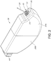
- FIG. 2 is a perspective view of the electrochemical cell 10 shown in FIG. 1 , but with the casing 12 having been removed from the electrode assembly 18.
- the electrode assembly 18 comprising an anode in electrochemical association with a cathode is housed inside a polymeric envelope 28.
- the polymeric envelope 28 is comprised of a right-side portion 28A that is mated to a left-side portion 28B.
- the right-side polymeric portion 28A is contoured to fit snugly over the electrode assembly 18 and has an opening 30 that is sized and shaped to receive the GTMS 20.
- the left-side portion 28B With the right-side portion of the polymeric envelope in place, the left-side portion 28B is moved over the left end of the electrode assembly 18 until it mates with the right-side envelope portion 28A.
- the left-side envelope portion 28B is somewhat larger than the right-side portion 28A so that the end of the right-side portion is received inside the left-side portion in a snug-fitting relationship.
- the right-side envelope portion 28A is somewhat larger than the left-side portion 28B so that the end of the left-side portion is received inside the right-side portion in a snug-fitting relationship.
- FIGs. 3 to 8 illustrate that the electrode assembly 18 is comprised of a relatively long or elongate plate-shaped anode 32 comprising an anode active material, for example lithium, supported on an anode current collector.
- anode active material for example lithium
- Suitable materials for the anode current collector include nickel, titanium, and aluminum.
- the anode is folded into a serpentine configuration as described in U.S. Patent No. 5,147,737 to Post et al. , which is assigned to the assignee of the present invention and incorporated herein by reference.
- nine cathode plates 34A, 34B, 34C, 34D, 34E, 34F, 34G, 34H and 341 reside or are interleaved between adjacent folds of the serpentine anode 32. While nine cathode plates are shown in the exemplary electrochemical cell 10, it is within the scope of the present disclosure that there can be as few as two cathode plates up to many more than nine plates. Twenty to fifty plates are possible in some cell designs.
- the serpentine anode is of a length that is sufficient to have an adequate number of folds so that a cathode plate is nested or interleaved in a fold with the major sides of each cathode plate facing directly to a portion of the anode.
- Each cathode plate is comprised of a cathode current collector (not shown) supporting a cathode active material on its opposed major faces or sides.
- the cathode plates 34A, 34B, 34C, 34D, 34E, 34F, 34G, 34H and 341 are contained in their own separator envelope (not numbered) so that when the cathode plates are interleaved between folds of the serpentine anode, a short-circuit does not occur.
- lithium as an exemplary anode active material is supported on the opposed major sides or faces of the anode current collector except for the side portions of the serpentine anode 32 facing outwardly next to the first cathode plate 36A and the ninth cathode plate 361.
- the cathode plates 34A, 34B, 34C, 34D, 34E, 34F, 34G, 34H and 341 are provided with respective extending tabs 36A, 36B, 36C, 36D, 36E, 36F, 36G, 36H and 341.
- FIG. 3 shows that the first cathode tab 36A extends outwardly from its current collector in a substantially co-planar relationship.
- the other cathode tabs 36B to 361 are bent so that each one lays on top of the next immediately adjacent tab in a stacked relationship. In that respect, the second cathode tab 36B is bent so that it lays against an inner surface of the first cathode tab 36A.
- the third cathode tab 36C is bent so that it lays against an inner surface of the second cathode tab 36B.
- the fourth cathode tab 36D is bent so that it lays against an inner surface of the third cathode tab 36C.
- the fifth cathode tab 36E is bent so that it lays against an inner surface of the fourth cathode tab 36D.
- the sixth cathode tab 36F is bent so that it lays against an inner surface of the fifth cathode tab 36E.
- the seventh cathode tab 36G is bent so that it lays against an inner surface of the sixth cathode tab 36F.
- the eighth cathode tab 36H is bent so that it lays against an inner surface of the seventh cathode tab 36G.
- the ninth cathode tab 361 is bent so that it lays against an inner surface of the eighth cathode tab 36H.
- a metal strip 38 having a length extending from a proximal portion 38A having a proximal end 38A' to a distal portion 38B having a distal end 38B' and serving as a cathode lead is wrapped around the stacked tabs.
- the proximal portion 38A of the metal strip 38 is bent into a L-shaped configuration and contacted to the aligned edges of the nine tabs and the outer surface of the first cathode tab 36A.
- the opposed distal portion 38B of the metal strip has an axial slot 40, preferably centered, that receives the proximal end of the terminal pin 26 comprising the GTMS 20.
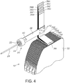
- FIG. 4 shows that the proximal portion 38A ( FIG. 3 ) of the metal strip is bent so that it lays against the inner surface of the ninth cathode tab 361. In this position, the proximal end 38A' ( FIG. 3 ) of the metal strip 38 is substantially aligned with the edges of the nine tabs 34A to 341 opposite the bend in the initial L-shaped strip configuration shown in FIG. 3 .
- the distal portion 38B ( FIG. 3 ) of the metal strip connected to the GTMS 20 is then bent backwards 180° so that it lays against the proximal portion 38A of the strip contacting the inner surface of the ninth cathode tab 361.
- the metal strip now has the shape of a strip-shaped hoop surrounding or encircling the cathode tabs 36A to 361.
- a welding device for example a laser welder (not shown), is used to connect the backwards bent distal portion 38B to the underlying proximal portion 38A of the metal strip with a series of welds 42.
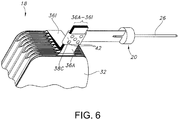
- FIG. 6 shows that the welds 42 penetrate completely through the distal portion 38B of the metal strip laying over the proximal portion 38A and through the nine cathode tabs 36A to 361 and then to an intermediate portion 36C of the metal strip.
- the intermediate portion 38C resides between the proximal portion 38A and the distal portion 38B of the metal strip.
- five welds are shown, that is not intended to be limiting. A lesser or greater number of welds 42 is contemplated by the scope of the present disclosure.
- the metal strip 38 is securely connected to the bent and overlying cathode tabs 36A to 361 so that the strip serves as a band or hoop that confines and joins the cathode tabs together, and that the welds penetrate completely through the various layers so that the welds 42 exist on the "back side" at the intermediate strip portion 38C. That way, weld integrity is visually verifiable from both sides of the hoop-shaped metal strip 38.
- FIGs. 5 and 6 illustrate that the cathode tabs 36A to 361 are trimmed so that their cut ends are a short distance spaced above the metal band 38 to thereby leave a bundle of extending stubs of the cathode tabs.
- FIG. 7 shows that the banded cathode tabs 36A to 361 have now been folded so that a distal portion of the ninth tab 361 faces its proximal portion in an overlaid relationship.
- the metal strip 38 resides between the proximal and distal portions of the ninth cathode tab 361.
- An outwardly facing side of the first tab 36A distant the ninth tab 361 is spaced furthest from the electrode assembly 18.
- the metal strip 38 is bent at a right angle proximate the aligned edges of the cathode tabs 36A to 361.
- the axis of the terminal pin 26 is substantially perpendicular to the outwardly facing side of the first tab 36A.
- FIG. 8 is a side view of this configuration.
- FIG. 9 shows that the metal strip 38 is then bent into a semi-looped configuration with the axis of the terminal pin 26 being substantially at a 45° angle with respect to the outwardly facing side of the first cathode tab 36A.
- FIG. 10 shows the electrode assembly 18 housed in the polymeric envelope 28 with the ferrule 22 of the GTMS 20 secured in the appropriately sized opening 30 in the casing.
- the anode current collector (not shown) is provided with anode tabs 44A, 44B that are connected to an inner surface of the casing.
- the negative terminal is completed with a negative terminal pin 48 connected to the casing 12 by a weld 50.
- FIGs. 1 and 10 illustrate that the negative terminal pin 48 is aligned side-by-side with the positive or cathode terminal pin 26.
- the welds 46 must penetrate completely through the anode tabs 44A, 44B to mechanically contact the inner surface of the casing 12. This contact can be at any one of the casing sidewalls including the surrounding edge wall 14A and the front and back sidewalls 14B, 14C.
- the anode tabs 44A, 44B are of a thinner material than that of the casing sidewalls 14A, 14B and 14C. Typical thicknesses for the anode tabs 44A, 44B range from about 0.00015" to about 0.0003", preferably about 0.0002", while typical thicknesses for the casing sidewalls range from about 0.010" to about 0.020", preferably about 0.012".
- the anode tabs 44A, 44B and the casing sidewalls are of dissimilar materials, which makes forming a robust connection somewhat more difficult than if they were of the same or similar materials.
- the anode tabs 44A, 44B are selected from nickel, titanium, and aluminum and the casing is selected from stainless-steel, titanium, and aluminum.
- An exemplary cell design has nickel as a preferred anode current collector material supporting lithium as an anode active material and stainless-steel as a typical casing material.
- the anode tabs 44A, 44B extending from each end of the elongate anode current collector are first in an unbent, outwardly extending configuration.
- Tab 44A is first bent inwardly toward tab 44B along a first crease 52A that is proximate the left-side portion 28B of the polymeric envelope 28.
- tab 44B is bent upwardly along a second crease 52B so that it lays against tab 44A.
- the tabs 44A, 44B are then both bent backwardly along a third crease 52C toward the edge of the polymeric envelope portion 28A from which tab 44A extends to assume the configuration shown in FIG. 13 .
- the thusly constructed electrode assembly including the bent anode tabs 44A, 44B is then housed inside the open-ended casing 12 for weld connection of the tabs to the casing serving as the anode terminal.
- FIG. 14 is a prior art schematic of a welding assembly 100 for tack welding the anode tabs 44A, 44B shown in FIG. 13 to a sidewall of the casing 12.
- the welding assembly 100 comprises the casing 12 with the anode tabs 44A, 44B laying against an inside surface thereof. This assembly is positioned between a stationary welding electrode 102 and a movable welding electrode 104. As the electrode 104 moves into contact with anode tab 44A, the anode tabs 44A, 44B and the casing 12 are clamped between the electrodes 102, 104.
- the welding electrodes 102, 104 are electrically connected to a resistance welding power source and control unit 106 which effects the weld connection of the tabs 44A, 44B to each other and to the casing 12.
- the anode tabs are of the same material, the main reason for the lack of heat generated between the two nickel layers is due to their high relatively conductivity and relatively low thickness of about 0.0002". This creates lower bulk heating in the exemplary nickel current collector tabs 44A, 44B and more importantly a lower contact resistance between the two nickel layers.
- FIG. 14 illustrates this where R1 is the bulk resistance of the movable welding electrode 104, R2 is the contact resistance between electrode 104 and anode tab 44A, R3 is the bulk resistance of anode tab 44A, R4 is the contact resistance between anode tabs 44A and 44B, R5 is the bulk resistance of anode tab 44B, R6 is the contact resistance between anode tab 44B and the casing 12, R7 is the bulk resistance of the casing 12, R8 is the contact resistance between the casing 12 and the stationary welding electrode 102 and R9 is the bulk resistance of the welding electrode 102 and the contact joints and cables 108, 110 to the resistance welding power source and control unit 106.
- R6 and R7 are suitable for generating enough heat for joining the anode tab 44B to the casing with a good bond that is desired for an implantable electrochemical cell application, and the like.
- R3, R4 and R5 may not generate enough heat for joining the anode tabs 44A, 44B together. Consequently, when a relatively low resistance welding electrode 104 is used, welding concerns such as sticking between the anode tabs 44A, 44B and between the welding electrode 104 and the anode tab 44A is not uncommon.
- Unsticking the welding electrode 104 from the anode tab 44A typically results in a torn tab, which is undesirable and means that the anode tab must be scrapped. Unsticking the welding electrode 104 from the anode tab 44A may also undesirably contaminate the tab with the material of the welding electrode 104, for example with copper from the electrode.
- a high resistance transferrable electrode tip 112 of bulk resistance R1' is added to the end of the movable electrode 104 according to the present disclosure.
- the transferrable electrode tip 112 is of a refractory metal and is preferably stainless-steel.
- the relatively high bulk resistance of the transferrable electrode tip 112 helps to focus or drive the heat generated by the movable welding electrode 104 through the contact resistance R2 between electrode 104 and anode tab 44A, through the bulk resistance R3 of anode tab 44A, through the contact resistance R4 between anode tabs 44A and 44B, through the bulk resistance R5 of anode tab 44B, through the contact resistance R6 between anode tab 44B and the casing 12, through the bulk resistance R7 of the casing 12, through the contact resistance R8 between the casing 12 and the stationary welding electrode 102 and to the bulk resistance R9 of the welding electrode 102.
- the melting temperature of the copper stationary and movable welding electrodes 102 and 104 is about 1,085°C (about 1,984°F)
- of grade 304 stainless-steel is from about 1,400°C to about 1,450°C (about 2,552°F to about 2,642°F)
- of grade 316 stainless-steel is from about 1,375°C to about 1,400°C (about 2,507°F to about 2,552°F)
- nickel is about 1,455°C (about 2,651°F)
- titanium is about 1,668°C (3,034°F)
- aluminum is about 660.3°C (1,221°F).
- the transferrable electrode tip creates a resistive balance between the ball and case that helps to direct or concentrate the heat generated by the welding electrodes so that the anode tabs are mechanically welded together at a "point" contact or point weld 46.
- the movable electrode 104 translates axially away from the welded cell assembly, leaving the transferrable electrode tip 112 behind as a transferred and affixed electrode tip 112A ( FIG. 11 ) portion of the weld 46.
- the finished casing 12 is removed from the welding assembly 100 and another casing 12/anode tab 44A, 44B subassembly is moving into position for the next welding operation.
- the transferrable electrode tip 112 compensates for the various resistance R3, R4 and R5 of the conductive anode tabs 44A, 44B, for example the nickel anode tabs, not generating a sufficient amount of heat during resistance welding to be readily joined together and to the casing.
- the present welding technique works similarly well when only one anode tab is being welded to the casing or when three, four, five, six or more anode tabs are being welded together and to the casing.
- This is a function of the transferrable electrode tip 112 having a relatively smaller mass than that of the anode tabs.
- the transferrable electrode tip 112 is a stainless-steel ball having a diameter of from about 0.03 inches to about 0.06 inches, preferable about 0.04 inches.
- the transferrable electrode tip 112 is likewise being of titanium or, the casing can be of titanium and the transferrable electrode tip 112 is stainless-steel.
- the transferrable electrode tip 112 is preferably a round ball having a shape similar to a BB shot pellet, that should not be considered as a limitation of the present disclosure.
- the transferrable electrode tip 112 can have the shape of a cone, a square cube, a rectangular cube, or any other irregular shape that is suitable for the cell design being manufactured.
- the electrochemical cell 10 can be of a primary or a secondary chemistry.
- the anode comprises metals capable of alloying with lithium at potentials below 1.0 V vs. lithium, such as Sn, Si, Al, B, Si-B, and composites of those metals with inactive metals to reduce volume expansion.
- the form of the anode may vary, but preferably it is of a thin sheet or foil that is pressed, evaporation, or rolled on the metallic anode current collector.
- the cathode of a primary cell is of electrically conductive material, preferably a solid material.
- the solid cathode may comprise a metal element, a metal oxide, a mixed metal oxide, and a metal sulfide, and combinations thereof.
- a preferred cathode active material is selected from the group consisting of silver vanadium oxide (SVO), copper silver vanadium oxide, manganese dioxide, cobalt nickel, nickel oxide, copper oxide, copper sulfide, iron sulfide, iron disulfide, titanium disulfide, copper vanadium oxide, carbon monofluoride (CF x ), and mixtures thereof.
- the cathode active material is mixed with a binder material such as a powdered fluoro-polymer, more preferably powdered polytetrafluoroethylene or powdered polyvinylidene fluoride (PVDF) present at about 1 to about 5 weight percent of the cathode mixture.
- a binder material such as a powdered fluoro-polymer, more preferably powdered polytetrafluoroethylene or powdered polyvinylidene fluoride (PVDF) present at about 1 to about 5 weight percent of the cathode mixture.
- PVDF powdered polytetrafluoroethylene or powdered polyvinylidene fluoride
- a conductive diluent is preferably added to the cathode mixture to improve conductivity.
- Suitable materials for this purpose include acetylene black, carbon black and/or graphite or a metallic powder such as powdered nickel, aluminum, titanium and stainless steel.
- the preferred cathode active mixture for the electrochemical cell 10 includes a powdered fluoro-polymer binder present at about 3 weight percent, a conductive diluent present at about 3 weight percent, and about 94 weight percent of the cathode active material.
- the primary electrochemical cell 10 includes a nonaqueous, ionically conductive electrolyte having an inorganic, ionically conductive salt dissolved in a nonaqueous solvent and, more preferably, a lithium salt dissolved in a mixture of a low viscosity solvent and a high permittivity solvent.
- the salt serves as the vehicle for migration of the anode ions to intercalate or react with the cathode active material and suitable salts include LiPF 6 , LiBF 4 , LiAsF 6 , LiSbF 6 , LiClO 4 , LiO 2 , LiAlCl 4 , LiGaCl 4 , LiC(SO 2 CF 3 ) 3 , LiN(SO 2 CF 3 ) 2 , LiSCN, LiO 3 SCF 3 , LiC 6 F 5 SO 3 , LiO 2 CCF 3 , LiSO 6 F, LiB(C 6 H 5 ) 4 , LiCF 3 SO 3 , and mixtures thereof.
- suitable salts include LiPF 6 , LiBF 4 , LiAsF 6 , LiSbF 6 , LiClO 4 , LiO 2 , LiAlCl 4 , LiGaCl 4 , LiC(SO 2 CF 3 ) 3 , LiN(SO 2 CF 3 ) 2 ,
- Suitable low viscosity solvents include esters, linear and cyclic ethers and dialkyl carbonates such as tetrahydrofuran (THF), methyl acetate (MA), diglyme, trigylme, tetragylme, dimethyl carbonate (DMC), 1,2-dimethoxyethane (DME), 1,2-diethoxyethane (DEE), 1-ethoxy,2-methoxyethane (EME), ethyl methyl carbonate, methyl propyl carbonate, ethyl propyl carbonate, diethyl carbonate, dipropyl carbonate, and mixtures thereof.
- THF tetrahydrofuran
- MA methyl acetate
- DMC 1,2-dimethoxyethane
- DEE 1,2-diethoxyethane
- EME 1-ethoxy,2-methoxyethane
- ethyl methyl carbonate methyl propyl carbonate, ethyl propyl carbon
- High permittivity solvents include cyclic carbonates, cyclic esters and cyclic amides such as propylene carbonate (PC), ethylene carbonate (EC), butylene carbonate, acetonitrile, dimethyl sulfoxide, dimethyl, formamide, dimethyl acetamide, ⁇ -valerolactone, ⁇ -butyrolactone (GBL), N-methyl-pyrrolidinone (NMP), and mixtures thereof.
- the preferred electrolyte for a lithium primary cell 10 is 0.8M to 1.5M LiAsF 6 or LiPF 6 dissolved in a 50:50 mixture, by volume, of PC as the preferred high permittivity solvent and DME as the preferred low viscosity solvent.
- the active material of the cathode is silver vanadium oxide (SVO) as described in U.S. Pat. Nos. 4,310,609 and 4,391,729 to Liang et al. , or copper silver vanadium oxide as described in U.S. Pat. Nos. 5,472,810 and 5,516,340 to Takeuchi et al. , all assigned to the assignee of the present invention, the disclosures of which are hereby incorporated by reference.
- SVO silver vanadium oxide
- Another embodiment of the present disclosure has the cathode plates 34A, 34B, 34C, 34D, 34E, 34F, 34G, 34H and 341 each of the configuration: SVO/first current collector/CF x /second current collector/SVO, wherein SVO is silver vanadium oxide.
- This alternate embodiment for the cathode plates is described in U.S. Patent No. 6,551,747 to Gan , which is assigned to the assignee of the present invention and incorporated herein by reference. Again, twenty to fifty plates, each of the configuration: SVO/first current collector/CF x /second current collector/SVO are contemplated in some cell designs.
- the anode in addition to lithium, can comprise a material capable of intercalating and de-intercalating an alkali metal, and preferably lithium.
- a carbonaceous anode comprising any of the various forms of carbon (e.g., coke, graphite, acetylene black, carbon black, glassy carbon, etc.), which are capable of reversibly retaining the lithium species, is preferred.
- Graphite is particularly preferred due to its relatively high lithium-retention capacity.
- fibers of the carbonaceous material are particularly advantageous because they have excellent mechanical properties that permit them to be fabricated into rigid electrodes capable of withstanding degradation during repeated charge/discharge cycling.
- the cathode of the exemplary secondary electrochemical cell 10 preferably comprises a lithiated material that is stable in air and readily handled.
- air-stable lithiated cathode materials include oxides, sulfides, selenides, and tellurides of such metals as vanadium, titanium, chromium, copper, molybdenum, niobium, iron, nickel, cobalt and manganese.
- the more preferred oxides include LiNiO 2 , LiMn 2 O 4 , LiCoO 2 , LiCo 0.92 Sn 0.08 O 2 , LiCo 1-x Ni x O 2 , LiFePO 4 , LiNi x Mn y Co 1-x-y O 2 , and LiNi x Co y Al 1-x-y O 2 .
- the lithiated active material is preferably mixed with a conductive additive selected from acetylene black, carbon black, graphite, and powdered metals of nickel, aluminum, titanium and stainless steel.
- the cathode further comprises a fluoro-resin binder, preferably in a powder form, such as PTFE, PVDF, ETFE, polyamides and polyimides, and mixtures thereof.
- the respective anode and cathode current collectors are selected from stainless steel, titanium, tantalum, platinum, gold, aluminum, cobalt nickel alloys, highly alloyed ferritic stainless steel containing molybdenum and chromium, and nickel-, chromium- and molybdenum-containing alloys. Nickel is preferred for the anode current collector supporting lithium and aluminum is preferred for the cathode current collectors.
- Suitable secondary electrochemical systems are comprised of nonaqueous electrolytes of an inorganic salt dissolved in a nonaqueous solvent and more preferably an alkali metal salt dissolved in a quaternary mixture of organic carbonate solvents comprising dialkyl (non-cyclic) carbonates selected from dimethyl carbonate (DMC), diethyl carbonate (DEC), dipropyl carbonate (DPC), ethyl methyl carbonate (EMC), methyl propyl carbonate (MPC), and ethyl propyl carbonate (EPC), and mixtures thereof, and at least one cyclic carbonate selected from propylene carbonate (PC), ethylene carbonate (EC), butylene carbonate (BC), and vinylene carbonate (VC), and mixtures thereof.
- Organic carbonates are generally used in the electrolyte solvent system for such battery chemistries because they exhibit high oxidative stability toward cathode materials and good kinetic stability toward anode materials.
- the cell casing 12 is filled with the appropriate electrolyte described hereinabove through a fill opening or port in the casing.
- the opening is then hermetically sealed such as by close-welding a plug (not shown) in the fill opening using a laser.
- the present disclosure relates to an electrochemical cell 10 comprising an electrode assembly 18 formed from an elongate anode that is folded into a serpentine configuration with a plurality of cathode plates 34A to 34I nested or interleaved between the folds.
- the tabs are folded into an overlapping and stacked relationship with each cathode tab touching its immediately adjacent neighbor tab.
- the proximal end of a metal strip 38 serving as a cathode lead is wrapped around the stacked cathode tabs and then a laser is used to weld through all layers of the metal strip 38 serving as a hoop and each of the bound cathode tabs.
- the laser welds are visible from the opposite side of the strip-shaped hoop surrounding the stacked cathode tabs from which the welding device, for example the laser beam of a laser welder, first contacts the assembly. This provides the welding engineer with a visual indication that the welded connection of the metal strip-shaped hoop to the stacked cathode tabs is robust and structurally sound.
- the distal end of the metal strip 38 is provided with an axial slot 40 that receives the proximal end of a cathode terminal pin 26.
- the terminal pin which is welded to the metal strip 38, is part of a hermetic glass-to-metal seal (GTMS) 20. With the GTMS hermetically secured in an opening in the cell casing 12, the terminal pin 26 is electrically isolated from the casing 12 with the plurality of cathode plates being electrically connected to each other through the welded metal strip 38.
- GTMS hermetic glass-to-metal seal
- anode tabs 44A, 44B extending from the opposite ends of the serpentine anode are resistance welded to an inner surface of the casing 12 using the welding assembly 100 shown in FIG. 15 including the transferrable electrode tip 112.
- the resulting weld or welds 46 have a profile of: melted transferrable electrode tip 112 providing a transferred and affixed electrode tip 112A ( FIG. 11 ) welded to anode tab 44A welded to anode tab 44B in turn welded to the casing 12 according to the present disclosure.
- This welded configuration completes the case-negative design of the exemplary electrochemical cell 10.
- the cell 10 can have a case-positive configuration.
- a cell configuration has the cathode in the shape of a serpentine electrode with anode plates interleaved between adjacent folds.
- the serpentine cathode current collector also has at least one and preferably two cathode tabs extending outwardly therefrom. It is these tabs that are resistance welded to the casing 12 as described in detail hereinabove for the anode tabs 44A, 44B.
Abstract
Description
- This application claims priority to
U.S. Provisional Application Serial No. 62/722,475, filed on August 24, 2018 U.S. Patent Application Serial No. 16/504,423, filed on July 8, 2019 - The present invention generally relates to the conversion of chemical energy to electrical energy. More particularly, this invention may relate to an improvement in weld connecting the tab or tabs of an anode current collector to the casing of an electrochemical cell. In a case-negative design, the casing is the anode terminal. A terminal pin electrically isolated from the casing may serve as the cathode terminal. Alternatively, in a case-positive cell configuration, the present invention may relate to weld connecting the cathode tab or tabs of the cathode current collector to the casing with the terminal pin being the anode terminal.
- When connecting the tabs of a current collector to the casing of an electrochemical cell, resistance welding is commonly used. One noteworthy advantage over other joining techniques is that with resistance welding the anode tab is clamped against the cell casing, which keeps the two parts in their intended position prior to the weld being formed. Resistance welding is also a simple one-step process that can be used at locations within the casing that are relatively hard to access.
- Materials such as nickel, titanium, and aluminum, which are commonly used for the anode current collector including its tabs, have relatively high electrical conductivity and corrosion resistivity. Stainless-steel, titanium, and aluminum are typical casing materials, and they have relatively high electrical resistivity in comparison to the commonly used anode current collector materials. Welding electrodes are commonly made of copper. Since the resistivity of copper is significantly lower than that of the anode current collector materials, for example nickel, there can be some amount of copper softening so that when the welding operation is completed, and the movable welding electrode is being withdrawn from the anode current collector tab, the welding electrode can stick to the anode tab. At the least, there can be copper contamination left behind on the anode tab. In effect, the copper welding electrode has welded itself to the nickel anode tab and breaking this connection can cause the anode tab to tear or pull away from the casing to which it is being welded.
- Moreover, when two anode tabs are stacked one upon the other, it is not uncommon for the anode tabs to not weld to each other in a robust manner that is desired for implantable medical applications. The best way to determine this is to subject the anode tabs to a pull test, which is not only an added and time-consuming step but, as discussed above, can be difficult to perform when the anode tabs are welded to the cell casing in a hard to access location.
- Further, the challenge of resistance welding an exemplary nickel anode current collector tab to an exemplary stainless-steel casing is augmented by the difference is thicknesses of the two materials. A typical anode current collector has a thickness of about 0.0002 inches while a casing is typically about 0.012 inches thick. Any sticking of the movable copper welding electrode to the anode tab can easily result in damage such as tearing of the tab as the welding electrode is withdrawn.
- Thus, there is a need for a new welding technique that is repeatable and suitable for joining two dissimilar materials together, such as the tab of an anode current collector to the casing of an electrochemical cell. Moreover, the new welding technique must produce a robust weld when two layers of the same material are being joined to each other. That is the situation when two anode tabs are stacked one upon the other and then welded to the cell casing. The present welding technique provides such a new welding technique.
- Aspects and embodiments of the invention are set out in the appended claims.
-
-
FIG. 1 is a perspective view of anelectrochemical cell 10 according to the present disclosure. -
FIG. 2 is a perspective view of thecell 10 shown inFIG. 1 , but with thecasing 12 removed and theelectrode assembly 18 housed in apolymeric envelope 28. -
FIG. 3 is a perspective view, partly broken away, showing the extendingcathode tabs 36A to 361 folded into a stacked configuration with the proximal portion of a metal strip-shaped hoop 38 supporting a distal glass-to-metal seal 20 partially folded around the tabs. -
FIG. 4 is a perspective view, partly broken away, showing the strip-shaped hoop 38 ofFIG. 3 encircling the bundledcathode tabs 36A to 361 and connected thereto withwelds 42. -
FIG. 5 is a perspective view, partly broken away, showing thetrimmed cathode tabs 36A to 361 with the encircling strip-shaped hoop 38. -
FIG. 6 is a perspective view, partly broken away, of the configuration illustrated inFIG. 5 , but from an opposite perspective. -
FIG. 7 is a perspective view, partly broken away, of theelectrode assembly 18 illustrated inFIG. 6 , but with thecathode tabs 36A to 361 bent over theelectrode assembly 18 and the strip-shaped hoop 38 bent so that the outwardly extendingterminal pin 26 is substantially perpendicular to the upper edge of the electrode assembly. -
FIG. 8 is a partly broken away, side elevational view of the strip-shaped hoop 38 encircling thecathode tabs 36A to 361 and the extendingterminal pin 26. -
FIG. 9 is a partly broken away, side elevational view of a distal portion of the strip-shaped hoop 38 ofFIG. 8 bent into a semi-looped configuration. -
FIG. 10 is a partly broken away, side elevational view of theelectrode assembly 18 housed inside themetal casing 12 for theelectrochemical cell 10 shown inFIG. 1 . -
FIG. 11 is a cross-sectional view taken along line 11-11 ofFIG. 10 . -
FIG. 12 is a partially broken-away, perspective view of twoanode tabs polymeric envelope 28B housing the anode and cathode shown inFIGs. 3 to 7 . -
FIG. 13 is a partially broken-away, perspective view of theanode tabs FIG. 12 after they have been bent into a configuration for weld connection to a sidewall of thecell casing 12. -
FIG. 14 is a schematic view of awelding assembly 100 for resistance welding theanode tabs FIG. 13 to thecell casing 12 according to the prior art. -
FIG. 15 is a partial schematic view of thewelding assembly 100 shown inFIG. 14 , but with an addedtransferrable electrode tip 112 for resistance welding theanode tabs casing 12 according to the present disclosure. - The new weld design disclosed herein may overcome the drawbacks of prior art resistance welding techniques with the result that welds between the anode tabs and the cell casing are robust and consistence from one weld to the next. According to the present disclosure, a relatively high resistance material, referred to as a transferable electrode tip, may be added between the movable welding electrode and the two or more stacked anode tabs being welded to a cell casing. The transferable electrode tip creates a resistive balance between the ball and case that helps to direct or concentrate the heat generated during the welding process so that the anode tabs are welded together at a "point" contact or point weld. For redundancy, it is preferred that at least two point-welds are made between the stacked anode tabs and the cell casing. Thus, the purpose of the transferable electrode tip is to improve process capability without adding any product functionality. Unless its removal, either partially or completely, is a mandatory requirement, the transferable electrode tip remains in the final weld as a transferred and affixed electrode tip.
- The foregoing and additional advantages and characterizing features of the present disclosure will become clearly apparent upon reading the ensuing description together with the included drawings.
- Turning now to the drawings,
FIG. 1 is a perspective view of anelectrochemical cell 10 according to the present disclosure. Thecell 10 is contained in a hermetically sealedcasing 12 comprising an open-ended container 14 closed by alid 16. After an electrode assembly 18 (FIGs. 3 to 7 ) is housed inside thecontainer 14, its open-end is closed by thelid 16. Thecontainer 14 comprises a surroundingedge wall 14A joined to a frontmajor sidewall 14B and a backmajor sidewall 14C. The front andback sidewalls electrochemical cell 10 is of mating clamshell portions as describes inU.S. Patent No. 6,613,474 to Frustaci et al. , which is assigned to the assignee of the present invention and incorporated herein by reference. Typical materials for the casing include stainless-steel, titanium, and aluminum. - The surrounding
edge wall 14A supports a glass-to-metal seal 20 (GTMS) comprising aferrule 22 connected to thecasing lid 16 in an appropriately sized opening, and a glass orceramic material 24 that hermetically seals between the ferrule and aterminal pin 26. Theterminal pin 26 extends from inside thecasing 12 where it is electrically connected to one of the anode and the cathode, preferably the cathode, to outside the casing for connection to a load to be powered by thecell 10. That way, the GTMS 20 electrically isolates theterminal pin 26 from thecasing 12 with the casing serving as the other terminal for the cell, typically the negative terminal electrically connected to the anode of theelectrode assembly 18. -
FIG. 2 is a perspective view of theelectrochemical cell 10 shown inFIG. 1 , but with thecasing 12 having been removed from theelectrode assembly 18. In that respect, this figure shows that theelectrode assembly 18 comprising an anode in electrochemical association with a cathode is housed inside apolymeric envelope 28. Thepolymeric envelope 28 is comprised of a right-side portion 28A that is mated to a left-side portion 28B. The right-sidepolymeric portion 28A is contoured to fit snugly over theelectrode assembly 18 and has anopening 30 that is sized and shaped to receive theGTMS 20. With the right-side portion of the polymeric envelope in place, the left-side portion 28B is moved over the left end of theelectrode assembly 18 until it mates with the right-side envelope portion 28A. In that respect, the left-side envelope portion 28B is somewhat larger than the right-side portion 28A so that the end of the right-side portion is received inside the left-side portion in a snug-fitting relationship. Alternatively, the right-side envelope portion 28A is somewhat larger than the left-side portion 28B so that the end of the left-side portion is received inside the right-side portion in a snug-fitting relationship. -
FIGs. 3 to 8 illustrate that theelectrode assembly 18 is comprised of a relatively long or elongate plate-shapedanode 32 comprising an anode active material, for example lithium, supported on an anode current collector. Suitable materials for the anode current collector include nickel, titanium, and aluminum. The anode is folded into a serpentine configuration as described inU.S. Patent No. 5,147,737 to Post et al. , which is assigned to the assignee of the present invention and incorporated herein by reference. - In the exemplary embodiment of the
electrochemical cell 10 illustrated in the drawings, ninecathode plates serpentine anode 32. While nine cathode plates are shown in the exemplaryelectrochemical cell 10, it is within the scope of the present disclosure that there can be as few as two cathode plates up to many more than nine plates. Twenty to fifty plates are possible in some cell designs. Regardless the number of cathode plates, however, the serpentine anode is of a length that is sufficient to have an adequate number of folds so that a cathode plate is nested or interleaved in a fold with the major sides of each cathode plate facing directly to a portion of the anode. - Each cathode plate is comprised of a cathode current collector (not shown) supporting a cathode active material on its opposed major faces or sides. The
cathode plates serpentine anode 32 facing outwardly next to thefirst cathode plate 36A and theninth cathode plate 361. - The
cathode plates tabs FIG. 3 shows that thefirst cathode tab 36A extends outwardly from its current collector in a substantially co-planar relationship. Theother cathode tabs 36B to 361 are bent so that each one lays on top of the next immediately adjacent tab in a stacked relationship. In that respect, thesecond cathode tab 36B is bent so that it lays against an inner surface of thefirst cathode tab 36A. Thethird cathode tab 36C is bent so that it lays against an inner surface of thesecond cathode tab 36B. Thefourth cathode tab 36D is bent so that it lays against an inner surface of thethird cathode tab 36C. Thefifth cathode tab 36E is bent so that it lays against an inner surface of thefourth cathode tab 36D. Thesixth cathode tab 36F is bent so that it lays against an inner surface of thefifth cathode tab 36E. Theseventh cathode tab 36G is bent so that it lays against an inner surface of thesixth cathode tab 36F. Theeighth cathode tab 36H is bent so that it lays against an inner surface of theseventh cathode tab 36G. And, theninth cathode tab 361 is bent so that it lays against an inner surface of theeighth cathode tab 36H. - With the
cathode tabs 36A to 361 in the bent and stacked relationship shown inFIG. 3 , ametal strip 38 having a length extending from aproximal portion 38A having aproximal end 38A' to adistal portion 38B having adistal end 38B' and serving as a cathode lead is wrapped around the stacked tabs. First, theproximal portion 38A of themetal strip 38 is bent into a L-shaped configuration and contacted to the aligned edges of the nine tabs and the outer surface of thefirst cathode tab 36A. The opposeddistal portion 38B of the metal strip has anaxial slot 40, preferably centered, that receives the proximal end of theterminal pin 26 comprising theGTMS 20. -
FIG. 4 shows that theproximal portion 38A (FIG. 3 ) of the metal strip is bent so that it lays against the inner surface of theninth cathode tab 361. In this position, theproximal end 38A' (FIG. 3 ) of themetal strip 38 is substantially aligned with the edges of the ninetabs 34A to 341 opposite the bend in the initial L-shaped strip configuration shown inFIG. 3 . - The
distal portion 38B (FIG. 3 ) of the metal strip connected to theGTMS 20 is then bent backwards 180° so that it lays against theproximal portion 38A of the strip contacting the inner surface of theninth cathode tab 361. The metal strip now has the shape of a strip-shaped hoop surrounding or encircling thecathode tabs 36A to 361. - A welding device, for example a laser welder (not shown), is used to connect the backwards bent
distal portion 38B to the underlyingproximal portion 38A of the metal strip with a series ofwelds 42.FIG. 6 shows that thewelds 42 penetrate completely through thedistal portion 38B of the metal strip laying over theproximal portion 38A and through the ninecathode tabs 36A to 361 and then to anintermediate portion 36C of the metal strip. Theintermediate portion 38C resides between theproximal portion 38A and thedistal portion 38B of the metal strip. Moreover, while five welds are shown, that is not intended to be limiting. A lesser or greater number ofwelds 42 is contemplated by the scope of the present disclosure. The important aspect is that themetal strip 38 is securely connected to the bent andoverlying cathode tabs 36A to 361 so that the strip serves as a band or hoop that confines and joins the cathode tabs together, and that the welds penetrate completely through the various layers so that thewelds 42 exist on the "back side" at theintermediate strip portion 38C. That way, weld integrity is visually verifiable from both sides of the hoop-shapedmetal strip 38. -
FIGs. 5 and6 illustrate that thecathode tabs 36A to 361 are trimmed so that their cut ends are a short distance spaced above themetal band 38 to thereby leave a bundle of extending stubs of the cathode tabs. -
FIG. 7 shows that the bandedcathode tabs 36A to 361 have now been folded so that a distal portion of theninth tab 361 faces its proximal portion in an overlaid relationship. In this configuration, themetal strip 38 resides between the proximal and distal portions of theninth cathode tab 361. An outwardly facing side of thefirst tab 36A distant theninth tab 361 is spaced furthest from theelectrode assembly 18. Then, themetal strip 38 is bent at a right angle proximate the aligned edges of thecathode tabs 36A to 361. In this configuration, the axis of theterminal pin 26 is substantially perpendicular to the outwardly facing side of thefirst tab 36A.FIG. 8 is a side view of this configuration. -
FIG. 9 shows that themetal strip 38 is then bent into a semi-looped configuration with the axis of theterminal pin 26 being substantially at a 45° angle with respect to the outwardly facing side of thefirst cathode tab 36A. -
FIG. 10 shows theelectrode assembly 18 housed in thepolymeric envelope 28 with theferrule 22 of theGTMS 20 secured in the appropriatelysized opening 30 in the casing. This drawing also illustrates that the anode current collector (not shown) is provided withanode tabs anode tabs anode tabs casing 12 is made withwelds 46. That way, thecasing 12 serves as the anode or negative terminal for thecell 10. The negative terminal is completed with a negativeterminal pin 48 connected to thecasing 12 by aweld 50.FIGs. 1 and10 illustrate that the negativeterminal pin 48 is aligned side-by-side with the positive orcathode terminal pin 26. - An important aspect of the present disclosure is that to ensure a robust connection, the
welds 46 must penetrate completely through theanode tabs casing 12. This contact can be at any one of the casing sidewalls including the surroundingedge wall 14A and the front and back sidewalls 14B, 14C. However, theanode tabs anode tabs anode tabs anode tabs - As shown in
FIG. 12 , theanode tabs Tab 44A is first bent inwardly towardtab 44B along afirst crease 52A that is proximate the left-side portion 28B of thepolymeric envelope 28. Then,tab 44B is bent upwardly along asecond crease 52B so that it lays againsttab 44A. Thetabs third crease 52C toward the edge of thepolymeric envelope portion 28A from whichtab 44A extends to assume the configuration shown inFIG. 13 . The thusly constructed electrode assembly including thebent anode tabs casing 12 for weld connection of the tabs to the casing serving as the anode terminal. -
FIG. 14 is a prior art schematic of awelding assembly 100 for tack welding theanode tabs FIG. 13 to a sidewall of thecasing 12. Thewelding assembly 100 comprises thecasing 12 with theanode tabs stationary welding electrode 102 and amovable welding electrode 104. As theelectrode 104 moves into contact withanode tab 44A, theanode tabs casing 12 are clamped between theelectrodes welding electrodes control unit 106 which effects the weld connection of thetabs casing 12. - While resistance welding relies on heat generated through the bulk resistance of the parts being joined and of the welding electrodes, most of the heat that is generated takes the form of contact resistance at the interfaces of the parts with each other and with the welding electrodes. In that respect, because so much heat is concentrated at the various contact resistance interfaces, the total amount of heat that is generated through electrical resistance of the current passing through the parts being joined is often enough to weld a single exemplary nickel anode tab to an exemplary stainless-steel casing. However, if the cell design has an anode with two or more current collector tabs stacked one upon the other, as in the presently illustrated
cell 10, a sufficient amount of heat may not be generated between the stacked anode tabs. Since the anode tabs are of the same material, the main reason for the lack of heat generated between the two nickel layers is due to their high relatively conductivity and relatively low thickness of about 0.0002". This creates lower bulk heating in the exemplary nickelcurrent collector tabs - In other words, when a cell design requires two or more layers of the same metal to be welded to each other, it is proposed that the clamping pressure exerted by the welding electrode can somewhat negate the contact resistance that normally exists between two different metals with the result that the two anode tab layers act more like a bulk layer of increased thickness than two layers of different materials. This phenomenon means that there is a need to improve the resistance between two metal layers being resistance welded together, such as occurs when two tabs of an exemplary nickel anode current collector are being welded to an exemplary stainless-steel cell casing.
-
FIG. 14 illustrates this where R1 is the bulk resistance of themovable welding electrode 104, R2 is the contact resistance betweenelectrode 104 andanode tab 44A, R3 is the bulk resistance ofanode tab 44A, R4 is the contact resistance betweenanode tabs anode tab 44B, R6 is the contact resistance betweenanode tab 44B and thecasing 12, R7 is the bulk resistance of thecasing 12, R8 is the contact resistance between thecasing 12 and thestationary welding electrode 102 and R9 is the bulk resistance of thewelding electrode 102 and the contact joints andcables control unit 106. - When joining an exemplary
nickel anode tab steel casing 12, at the inner and outer surfaces of the casing, R6 and R7 are suitable for generating enough heat for joining theanode tab 44B to the casing with a good bond that is desired for an implantable electrochemical cell application, and the like. However, R3, R4 and R5 may not generate enough heat for joining theanode tabs resistance welding electrode 104 is used, welding concerns such as sticking between theanode tabs welding electrode 104 and theanode tab 44A is not uncommon. Unsticking thewelding electrode 104 from theanode tab 44A typically results in a torn tab, which is undesirable and means that the anode tab must be scrapped. Unsticking thewelding electrode 104 from theanode tab 44A may also undesirably contaminate the tab with the material of thewelding electrode 104, for example with copper from the electrode. - In
FIG. 15 , a high resistancetransferrable electrode tip 112 of bulk resistance R1' is added to the end of themovable electrode 104 according to the present disclosure. Thetransferrable electrode tip 112 is of a refractory metal and is preferably stainless-steel. The relatively high bulk resistance of thetransferrable electrode tip 112 helps to focus or drive the heat generated by themovable welding electrode 104 through the contact resistance R2 betweenelectrode 104 andanode tab 44A, through the bulk resistance R3 ofanode tab 44A, through the contact resistance R4 betweenanode tabs anode tab 44B, through the contact resistance R6 betweenanode tab 44B and thecasing 12, through the bulk resistance R7 of thecasing 12, through the contact resistance R8 between thecasing 12 and thestationary welding electrode 102 and to the bulk resistance R9 of thewelding electrode 102. - The melting temperature of the copper stationary and
movable welding electrodes copper welding electrode weld 46. Moreover, if the copper electrode should melt in an appreciable manner, leaving any residue behind, that "contamination" is left on the transferred and affixedelectrode tip 112A (FIG. 11 ) portion of theweld 46, which is formed when thetransferrable electrode tip 112 at least partially melts during the welding operation, and not on the anode tabs. - In that manner, after the
anode tabs casing 12, themovable electrode 104 translates axially away from the welded cell assembly, leaving thetransferrable electrode tip 112 behind as a transferred and affixedelectrode tip 112A (FIG. 11 ) portion of theweld 46. Thefinished casing 12 is removed from thewelding assembly 100 and anothercasing 12/anode tab transferrable electrode tip 112 compensates for the various resistance R3, R4 and R5 of theconductive anode tabs - It is further noted that while the present disclosure is described with the anode having two
anode tabs transferrable electrode tip 112 having a relatively smaller mass than that of the anode tabs. When the casing is of stainless-steel, it is preferred that thetransferrable electrode tip 112 is a stainless-steel ball having a diameter of from about 0.03 inches to about 0.06 inches, preferable about 0.04 inches. If the cell casing is of titanium, another embodiment of the present disclosure has thetransferrable electrode tip 112 likewise being of titanium or, the casing can be of titanium and thetransferrable electrode tip 112 is stainless-steel. Moreover, while thetransferrable electrode tip 112 is preferably a round ball having a shape similar to a BB shot pellet, that should not be considered as a limitation of the present disclosure. Instead, thetransferrable electrode tip 112 can have the shape of a cone, a square cube, a rectangular cube, or any other irregular shape that is suitable for the cell design being manufactured. - The
electrochemical cell 10 can be of a primary or a secondary chemistry. If of a primary chemistry, the anode comprises metals capable of alloying with lithium at potentials below 1.0 V vs. lithium, such as Sn, Si, Al, B, Si-B, and composites of those metals with inactive metals to reduce volume expansion. The form of the anode may vary, but preferably it is of a thin sheet or foil that is pressed, evaporation, or rolled on the metallic anode current collector. - The cathode of a primary cell is of electrically conductive material, preferably a solid material. The solid cathode may comprise a metal element, a metal oxide, a mixed metal oxide, and a metal sulfide, and combinations thereof. A preferred cathode active material is selected from the group consisting of silver vanadium oxide (SVO), copper silver vanadium oxide, manganese dioxide, cobalt nickel, nickel oxide, copper oxide, copper sulfide, iron sulfide, iron disulfide, titanium disulfide, copper vanadium oxide, carbon monofluoride (CFx), and mixtures thereof.
- Before fabrication into an electrode for incorporation into the
electrochemical cell 10, the cathode active material is mixed with a binder material such as a powdered fluoro-polymer, more preferably powdered polytetrafluoroethylene or powdered polyvinylidene fluoride (PVDF) present at about 1 to about 5 weight percent of the cathode mixture. Further, up to about 10 weight percent of a conductive diluent is preferably added to the cathode mixture to improve conductivity. Suitable materials for this purpose include acetylene black, carbon black and/or graphite or a metallic powder such as powdered nickel, aluminum, titanium and stainless steel. The preferred cathode active mixture for theelectrochemical cell 10 includes a powdered fluoro-polymer binder present at about 3 weight percent, a conductive diluent present at about 3 weight percent, and about 94 weight percent of the cathode active material. - The primary
electrochemical cell 10 includes a nonaqueous, ionically conductive electrolyte having an inorganic, ionically conductive salt dissolved in a nonaqueous solvent and, more preferably, a lithium salt dissolved in a mixture of a low viscosity solvent and a high permittivity solvent. The salt serves as the vehicle for migration of the anode ions to intercalate or react with the cathode active material and suitable salts include LiPF6, LiBF4, LiAsF6, LiSbF6, LiClO4, LiO2, LiAlCl4, LiGaCl4, LiC(SO2CF3)3, LiN(SO2CF3)2, LiSCN, LiO3SCF3, LiC6 F5SO3, LiO2CCF3, LiSO6F, LiB(C6H5)4, LiCF3SO3, and mixtures thereof. - Suitable low viscosity solvents include esters, linear and cyclic ethers and dialkyl carbonates such as tetrahydrofuran (THF), methyl acetate (MA), diglyme, trigylme, tetragylme, dimethyl carbonate (DMC), 1,2-dimethoxyethane (DME), 1,2-diethoxyethane (DEE), 1-ethoxy,2-methoxyethane (EME), ethyl methyl carbonate, methyl propyl carbonate, ethyl propyl carbonate, diethyl carbonate, dipropyl carbonate, and mixtures thereof. High permittivity solvents include cyclic carbonates, cyclic esters and cyclic amides such as propylene carbonate (PC), ethylene carbonate (EC), butylene carbonate, acetonitrile, dimethyl sulfoxide, dimethyl, formamide, dimethyl acetamide, γ-valerolactone, γ-butyrolactone (GBL), N-methyl-pyrrolidinone (NMP), and mixtures thereof. The preferred electrolyte for a lithium
primary cell 10 is 0.8M to 1.5M LiAsF6 or LiPF6 dissolved in a 50:50 mixture, by volume, of PC as the preferred high permittivity solvent and DME as the preferred low viscosity solvent. - By way of example, in an illustrative electrochemical cell, the active material of the cathode is silver vanadium oxide (SVO) as described in
U.S. Pat. Nos. 4,310,609 and4,391,729 to Liang et al. , or copper silver vanadium oxide as described inU.S. Pat. Nos. 5,472,810 and5,516,340 to Takeuchi et al. , all assigned to the assignee of the present invention, the disclosures of which are hereby incorporated by reference. - Another embodiment of the present disclosure has the
cathode plates U.S. Patent No. 6,551,747 to Gan , which is assigned to the assignee of the present invention and incorporated herein by reference. Again, twenty to fifty plates, each of the configuration: SVO/first current collector/CFx/second current collector/SVO are contemplated in some cell designs. - In an exemplary secondary
electrochemical cell 10, in addition to lithium, the anode can comprise a material capable of intercalating and de-intercalating an alkali metal, and preferably lithium. A carbonaceous anode comprising any of the various forms of carbon (e.g., coke, graphite, acetylene black, carbon black, glassy carbon, etc.), which are capable of reversibly retaining the lithium species, is preferred. Graphite is particularly preferred due to its relatively high lithium-retention capacity. Regardless the form of carbon, fibers of the carbonaceous material are particularly advantageous because they have excellent mechanical properties that permit them to be fabricated into rigid electrodes capable of withstanding degradation during repeated charge/discharge cycling. - The cathode of the exemplary secondary
electrochemical cell 10 preferably comprises a lithiated material that is stable in air and readily handled. Examples of such air-stable lithiated cathode materials include oxides, sulfides, selenides, and tellurides of such metals as vanadium, titanium, chromium, copper, molybdenum, niobium, iron, nickel, cobalt and manganese. The more preferred oxides include LiNiO2, LiMn2O4, LiCoO2, LiCo0.92Sn0.08O2, LiCo1-x NixO2, LiFePO4, LiNixMnyCo1-x-yO2, and LiNixCoyAl1-x-yO2. - For the
electrochemical cell 10, the lithiated active material is preferably mixed with a conductive additive selected from acetylene black, carbon black, graphite, and powdered metals of nickel, aluminum, titanium and stainless steel. The cathode further comprises a fluoro-resin binder, preferably in a powder form, such as PTFE, PVDF, ETFE, polyamides and polyimides, and mixtures thereof. - The respective anode and cathode current collectors are selected from stainless steel, titanium, tantalum, platinum, gold, aluminum, cobalt nickel alloys, highly alloyed ferritic stainless steel containing molybdenum and chromium, and nickel-, chromium- and molybdenum-containing alloys. Nickel is preferred for the anode current collector supporting lithium and aluminum is preferred for the cathode current collectors.
- Suitable secondary electrochemical systems are comprised of nonaqueous electrolytes of an inorganic salt dissolved in a nonaqueous solvent and more preferably an alkali metal salt dissolved in a quaternary mixture of organic carbonate solvents comprising dialkyl (non-cyclic) carbonates selected from dimethyl carbonate (DMC), diethyl carbonate (DEC), dipropyl carbonate (DPC), ethyl methyl carbonate (EMC), methyl propyl carbonate (MPC), and ethyl propyl carbonate (EPC), and mixtures thereof, and at least one cyclic carbonate selected from propylene carbonate (PC), ethylene carbonate (EC), butylene carbonate (BC), and vinylene carbonate (VC), and mixtures thereof. Organic carbonates are generally used in the electrolyte solvent system for such battery chemistries because they exhibit high oxidative stability toward cathode materials and good kinetic stability toward anode materials.
- Whether of a primary or a secondary chemistry, the
cell casing 12 is filled with the appropriate electrolyte described hereinabove through a fill opening or port in the casing. The opening is then hermetically sealed such as by close-welding a plug (not shown) in the fill opening using a laser. - Thus, the present disclosure relates to an
electrochemical cell 10 comprising anelectrode assembly 18 formed from an elongate anode that is folded into a serpentine configuration with a plurality ofcathode plates 34A to 34I nested or interleaved between the folds. To make a robust and secure connection of therespective cathode tabs 36A to 36I to a cathode terminal, the tabs are folded into an overlapping and stacked relationship with each cathode tab touching its immediately adjacent neighbor tab. The proximal end of ametal strip 38 serving as a cathode lead is wrapped around the stacked cathode tabs and then a laser is used to weld through all layers of themetal strip 38 serving as a hoop and each of the bound cathode tabs. Preferably, the laser welds are visible from the opposite side of the strip-shaped hoop surrounding the stacked cathode tabs from which the welding device, for example the laser beam of a laser welder, first contacts the assembly. This provides the welding engineer with a visual indication that the welded connection of the metal strip-shaped hoop to the stacked cathode tabs is robust and structurally sound. - The distal end of the
metal strip 38 is provided with anaxial slot 40 that receives the proximal end of acathode terminal pin 26. The terminal pin, which is welded to themetal strip 38, is part of a hermetic glass-to-metal seal (GTMS) 20. With the GTMS hermetically secured in an opening in thecell casing 12, theterminal pin 26 is electrically isolated from thecasing 12 with the plurality of cathode plates being electrically connected to each other through the weldedmetal strip 38. - Moreover,
anode tabs casing 12 using thewelding assembly 100 shown inFIG. 15 including thetransferrable electrode tip 112. The resulting weld or welds 46 have a profile of: meltedtransferrable electrode tip 112 providing a transferred and affixedelectrode tip 112A (FIG. 11 ) welded toanode tab 44A welded toanode tab 44B in turn welded to thecasing 12 according to the present disclosure. This welded configuration completes the case-negative design of the exemplaryelectrochemical cell 10. - It is further within the scope of the present disclosure that the
cell 10 can have a case-positive configuration. Such a cell configuration has the cathode in the shape of a serpentine electrode with anode plates interleaved between adjacent folds. The serpentine cathode current collector also has at least one and preferably two cathode tabs extending outwardly therefrom. It is these tabs that are resistance welded to thecasing 12 as described in detail hereinabove for theanode tabs - It is appreciated that various modifications to the inventive concepts described herein may be apparent to those of ordinary skill in the art without departing from the spirit and scope of the present invention as defined by the appended claims.
Claims (16)
- An electrochemical cell, comprising:a) a casing;b) an electrode assembly housed inside the casing, the electrode assembly comprising:i) at least a first cathode comprising a first cathode active material contacted to a first cathode current collector, the first cathode current collector having a first cathode tab extending outwardly therefrom;ii) at least one anode comprising an anode active material contacted to an anode current collector, wherein the at least one anode is in electrochemical association with the first cathode, and wherein the anode has at least a first anode tab extending outwardly therefrom;iii) at least one anode weld electrically and mechanically connecting the first anode tab to the casing serving as a negative terminal for the cell; andiv) a separator residing between the anode and the first cathode; andc) a feedthrough comprising a terminal pin of a glass-to-metal seal supported by the casing, wherein the terminal pin extends from a terminal pin proximal end electrically connected to the cathode tab to a terminal pin distal end located outside the casing to thereby serve as a positive terminal for the cell; andd) an electrolyte in the casing activating the electrode assembly.
- The electrochemical cell of claim 1, wherein the at least one anode weld connecting the first anode tab to the casing has the following profile: an affixed electrode tip of a first metal, the first anode tab of a second metal, and the casing of a third metal, wherein the first and third metals are the same or different and they are different than the second metal of the anode tab; and
preferably wherein the affixed electrode tip is a ball having a diameter of from about 0.03 inches to about 0.06 inches. - The electrochemical cell of claim 2, wherein the affixed electrode tip is stainless-steel, the first anode tab is selected from the group consisting of nickel, titanium, and aluminum, and the casing is selected from the group consisting of stainless-steel, titanium, and aluminum; and
preferably wherein the affixed electrode tip is stainless-steel, the first anode tab is nickel, and the casing is stainless-steel. - The electrochemical cell of any of claims 1 to 3, wherein the at least one anode has the first anode tab and at least a second anode tab extending outwardly therefrom, and wherein the at least one weld electrically and mechanically connects the affixed electrode tip to the first anode tab, the first and second anode tabs to each other, and the second anode tab to the casing; and
preferably wherein the first and second anode tabs each have a thickness of about 0.0002 inches. - The electrochemical cell of any of claims 1 to 4, wherein the cathode comprises a second cathode comprising a second cathode active material contacted to a second cathode current collector, and wherein, with the first and second cathodes in a side-by-side arrangement, the at least one anode is positioned between the first and second cathodes.
- The electrochemical cell of any of claims 1 to 5, wherein the anode active material of the anode is comprised of lithium and the first cathode active material of the first cathode is selected from the group consisting of silver vanadium oxide, copper silver vanadium oxide, manganese dioxide, cobalt nickel, nickel oxide, copper oxide, copper sulfide, iron sulfide, iron disulfide, titanium disulfide, copper vanadium oxide, and mixtures thereof.
- The electrochemical cell of any of claims 1 to 5, wherein the anode active material of the anode is a carbonaceous material and the first cathode active material is selected from the group consisting of LiNiO2, LiMn2O4, LiCoO2, LiCo0.92Sn0.08O2, and lithium nickel cobalt oxide.
- An electrochemical cell, comprising:a) a casing;b) an electrode assembly housed inside the casing, the electrode assembly comprising:i) at least a first cathode and a second cathode, the first cathode comprising a first cathode active material contacted to a first cathode current collector, and the second cathode comprising a second cathode active material contacted to a second cathode current collector, wherein:A) the first cathode current collector has a first cathode tab extending outwardly from a first cathode tab proximal portion having a first cathode tab proximal end connected to the first cathode current collector to a first cathode tab distal portion, wherein the first cathode tab has opposed first and second major sides; andB) the second cathode current collector has a second cathode tab extending outwardly from a second cathode tab proximal portion having a second cathode tab proximal end connected to the second cathode current collector to a second cathode tab distal portion, wherein the second cathode tab has opposed third and fourth major sides,C) a cathode lead extending from a cathode lead proximal portion to a cathode lead distal portion, wherein, with the first and second cathodes in a side-by-side arrangement, a first section and a second section of the cathode lead proximal portion contact the respective fourth major side of the second cathode tab and the first major side of the first cathode tab with a third section of the cathode lead proximal portion contacting the first section of the cathode lead; andD) at least one cathode weld contacting the first, second and third sections of the cathode lead proximal portion and the first and second cathode tabs;ii) at least one anode comprising:A) an anode active material contacted to an anode current collector, wherein the at least one anode is positioned between the side-by-side first and second cathodes, and wherein the anode has at least a first anode tab extending outwardly from the anode current collector; andB) at least one anode weld electrically and mechanically connecting the first anode tab to the casing serving as a negative terminal for the cell; andiii) a separator residing between the anode and the first and second cathodes; andc) a feedthrough comprising a terminal pin of a glass-to-metal seal supported by the casing, wherein the terminal pin extends from a terminal pin proximal end electrically connected to the cathode lead distal portion to a terminal pin distal end located outside the casing to thereby serve as a positive terminal for the cell; andd) an electrolyte in the casing activating the electrode assembly.
- The electrochemical cell of claim 8, wherein the at least one anode weld electrically and mechanically connecting the first anode tab to the casing has the following profile: an affixed electrode tip of a first metal, the first anode tab of a second metal, and the casing of a third metal, wherein the first and third metals are the same or different and they are different than the second metal of the anode tab; and
preferably wherein the affixed electrode tip is a ball having a diameter of from about 0.03 inches to about 0.06 inches. - The electrochemical cell of claim 9, wherein the affixed electrode tip is stainless-steel, the first anode tab is nickel, and the casing is stainless-steel.
- The electrochemical cell of any of claims 8 to 10, wherein the at least one anode has the first anode tab and at least a second anode tab extending outwardly therefrom, and wherein the at least one anode weld electrically and mechanically connects the affixed electrode tip to the first and tab, and the first and second anode tabs to each other, and the second anode tab to the casing; and
preferably wherein the first and second anode tabs each have a thickness of about 0.0002 inches. - A method for providing an electrochemical cell, comprising the steps of:a) providing an open-ended container;b) providing an electrode assembly, comprising:i) at least a first cathode and a second cathode, the first cathode comprising a first cathode active material contacted to a first cathode current collector having a first cathode tab extending outwardly therefrom, and the second cathode comprising a second cathode active material contacted to a second cathode current collector having a second cathode tab extending outwardly therefrom;ii) providing a cathode lead, wherein, with the first and second cathodes in a side-by-side arrangement, connecting the cathode lead to the first and second cathode tabs;iii) providing an anode comprising an anode active material contacted to an anode current collector, the anode having at least a first anode tab extending outwardly from the anode current collector; andiv) positioning the anode between the side-by-side first and second cathodes with a separator residing between the anode and the first and second cathodes; andc) housing the electrode assembly inside the container and then connecting the first anode tab to the container serving as a negative terminal for the cell;d) providing a lid sized and shaped to close the open end of the container;e) securing a feedthrough comprising a terminal pin of a glass-to-metal seal in an opening in the lid;f) electrically connecting a proximal end of the terminal pin to the cathode lead distal portion;g) securing the lid to the container to close the open end thereof with a terminal pin distal end extending outside the casing to thereby serve as a positive terminal for the cell; andh) filling an electrolyte into the casing through a fill port and then closing the fill port.
- The method of claim 12, including positioning the anode tab contacting an inner surface of the casing between opposed resistance welding electrodes and then passing a current between the welding electrodes that is sufficient to weld the anode tab to the casing.
- The method of claim 12 or claim 13, including providing a transferrable electrode tip between a movable one of the resistance welding electrodes and the anode tab prior to welding the anode tab to the casing; and
preferably including providing the transferrable electrode tip being a ball having a diameter of from about 0.03 inches to about 0.06 inches. - The method of claim 14, including providing the movable one of the resistance welding electrodes comprising copper, the transferrable electrode tip comprising stainless-steel, the anode tab comprising nickel and the casing comprising stainless-steel.
- The method of any of claims 12 to 15, including providing the at least one anode having the first anode tab and at least a second anode tab extending outwardly therefrom, and stacking the first and second anode tabs together and positioning the stacked anode tabs between the opposed resistance welding electrodes and then passing a current between the welding electrodes that is sufficient to weld the first and second anode tabs to each other with the first anode tab welded to an affixed electrode tip and the second anode tab welded to the casing.
Applications Claiming Priority (2)
| Application Number | Priority Date | Filing Date | Title |
|---|---|---|---|
| US201862722475P | 2018-08-24 | 2018-08-24 | |
| US16/504,423 US11114661B2 (en) | 2018-07-13 | 2019-07-08 | Electrochemical cell having a serpentine anode with a plurality of interleaved cathode plates having extending tabs stacked and connected to each other by a welded surrounding metal hoop |
Publications (2)
| Publication Number | Publication Date |
|---|---|
| EP3614461A1 true EP3614461A1 (en) | 2020-02-26 |
| EP3614461B1 EP3614461B1 (en) | 2023-11-15 |
Family
ID=67766045
Family Applications (1)
| Application Number | Title | Priority Date | Filing Date |
|---|---|---|---|
| EP19193531.1A Active EP3614461B1 (en) | 2018-08-24 | 2019-08-26 | A transferable electrode tip for resistance welding an anode tab to the casing of an electrochemical cell |
Country Status (1)
| Country | Link |
|---|---|
| EP (1) | EP3614461B1 (en) |
Cited By (4)
| Publication number | Priority date | Publication date | Assignee | Title |
|---|---|---|---|---|
| CN112151779A (en) * | 2020-09-18 | 2020-12-29 | 深圳市贝特瑞纳米科技有限公司 | Binary anode composite material and preparation method and application thereof |
| WO2021263135A1 (en) * | 2020-06-25 | 2021-12-30 | Medtronic, Inc. | Shaped rechargeable battery electronic interconnect |
| CN114535801A (en) * | 2022-04-01 | 2022-05-27 | 柳州宏德激光科技有限公司 | Laser welding equipment for recycling power battery |
| WO2023082153A1 (en) * | 2021-11-11 | 2023-05-19 | 宁德时代新能源科技股份有限公司 | Battery cell, battery, electrical device, and battery cell preparation method and apparatus |
Citations (8)
| Publication number | Priority date | Publication date | Assignee | Title |
|---|---|---|---|---|
| US4310609A (en) | 1979-12-17 | 1982-01-12 | Wilson Greatbatch Ltd. | Metal oxide composite cathode material for high energy density batteries |
| US4391729A (en) | 1979-12-17 | 1983-07-05 | Wilson Greatbatch Ltd. | Metal oxide composite cathode material for high energy density batteries |
| US4964877A (en) * | 1986-01-14 | 1990-10-23 | Wilson Greatbatch Ltd. | Non-aqueous lithium battery |
| US5147737A (en) | 1991-05-07 | 1992-09-15 | Wilson Greatbatch Ltd. | Electrochemical cell with improved efficiency serpentine electrode |
| US5472810A (en) | 1993-03-17 | 1995-12-05 | W. Greatbatch Ltd. | Copper, silver, vanadium oxide composite cathode material for high energy density batteries |
| US5516340A (en) | 1993-03-17 | 1996-05-14 | Wilson Greatbatch Ltd. | Process for making a metal oxide composite cathode material for high energy density batteries |
| US6551747B1 (en) | 2000-04-27 | 2003-04-22 | Wilson Greatbatch Ltd. | Sandwich cathode design for alkali metal electrochemical cell with high discharge rate capability |
| US6613474B2 (en) | 2000-04-06 | 2003-09-02 | Wilson Greatbatch Ltd. | Electrochemical cell having a casing of mating portions |
-
2019
- 2019-08-26 EP EP19193531.1A patent/EP3614461B1/en active Active
Patent Citations (8)
| Publication number | Priority date | Publication date | Assignee | Title |
|---|---|---|---|---|
| US4310609A (en) | 1979-12-17 | 1982-01-12 | Wilson Greatbatch Ltd. | Metal oxide composite cathode material for high energy density batteries |
| US4391729A (en) | 1979-12-17 | 1983-07-05 | Wilson Greatbatch Ltd. | Metal oxide composite cathode material for high energy density batteries |
| US4964877A (en) * | 1986-01-14 | 1990-10-23 | Wilson Greatbatch Ltd. | Non-aqueous lithium battery |
| US5147737A (en) | 1991-05-07 | 1992-09-15 | Wilson Greatbatch Ltd. | Electrochemical cell with improved efficiency serpentine electrode |
| US5472810A (en) | 1993-03-17 | 1995-12-05 | W. Greatbatch Ltd. | Copper, silver, vanadium oxide composite cathode material for high energy density batteries |
| US5516340A (en) | 1993-03-17 | 1996-05-14 | Wilson Greatbatch Ltd. | Process for making a metal oxide composite cathode material for high energy density batteries |
| US6613474B2 (en) | 2000-04-06 | 2003-09-02 | Wilson Greatbatch Ltd. | Electrochemical cell having a casing of mating portions |
| US6551747B1 (en) | 2000-04-27 | 2003-04-22 | Wilson Greatbatch Ltd. | Sandwich cathode design for alkali metal electrochemical cell with high discharge rate capability |
Cited By (5)
| Publication number | Priority date | Publication date | Assignee | Title |
|---|---|---|---|---|
| WO2021263135A1 (en) * | 2020-06-25 | 2021-12-30 | Medtronic, Inc. | Shaped rechargeable battery electronic interconnect |
| CN112151779A (en) * | 2020-09-18 | 2020-12-29 | 深圳市贝特瑞纳米科技有限公司 | Binary anode composite material and preparation method and application thereof |
| WO2023082153A1 (en) * | 2021-11-11 | 2023-05-19 | 宁德时代新能源科技股份有限公司 | Battery cell, battery, electrical device, and battery cell preparation method and apparatus |
| CN114535801A (en) * | 2022-04-01 | 2022-05-27 | 柳州宏德激光科技有限公司 | Laser welding equipment for recycling power battery |
| CN114535801B (en) * | 2022-04-01 | 2022-09-27 | 柳州宏德激光科技有限公司 | Laser welding equipment for recycling power battery |
Also Published As
| Publication number | Publication date |
|---|---|
| EP3614461B1 (en) | 2023-11-15 |
Similar Documents
| Publication | Publication Date | Title |
|---|---|---|
| EP3614461B1 (en) | A transferable electrode tip for resistance welding an anode tab to the casing of an electrochemical cell | |
| US10170744B2 (en) | Electrochemical current collector screen designs utilizing ultrasonic welding | |
| US11114661B2 (en) | Electrochemical cell having a serpentine anode with a plurality of interleaved cathode plates having extending tabs stacked and connected to each other by a welded surrounding metal hoop | |
| JP4659861B2 (en) | Flat secondary battery and manufacturing method thereof | |
| JP6870914B2 (en) | Non-aqueous electrolyte batteries, battery packs and vehicles | |
| US10916740B2 (en) | Method of providing an electrochemical cell casing having an open-ended main body portion of grade 5 or 23 titanium closed by upper and lower lids of grade 1 or 2 titanium | |
| EP2023423A2 (en) | Non-prismatic electrochemical cell | |
| EP2325928B1 (en) | Direct resistance welding - self brazing of aluminum to molybdenum pin | |
| US20120282519A1 (en) | Dissimilar Material Battery Enclosure for Improved Weld Structure | |
| JP2000348768A (en) | Nitric ester additive for nonaqueous electrolytic solution in rechargeable electrochemical battery | |
| US10205151B2 (en) | Connector from the tab of an electrode current collector to the terminal pin of a feedthrough in an electrochemical cell | |
| KR20170032456A (en) | Nonaqueous electrolyte battery and battery pack | |
| US11355820B2 (en) | Transferable electrode tip for resistance welding an anode tab to the casing of an electrochemical cell | |
| US9300007B1 (en) | Ultrasonic welding of lithium onto a current collector | |
| JP5100441B2 (en) | Non-aqueous electrolyte battery | |
| JP2002237334A (en) | Double collector type negative electrode structure for alkaline metal ion battery | |
| EP3958391A1 (en) | Glass-to-metal seal terminal pin for an electrochemical cell | |
| JP6279707B2 (en) | Nonaqueous electrolyte battery and battery pack | |
| JP6931293B2 (en) | How to manufacture a secondary battery | |
| US20160271728A1 (en) | Laser welding-self brazing in medical power manufacturing | |
| JP4455008B2 (en) | Nonaqueous electrolyte secondary battery | |
| JP2008021431A (en) | Non-aqueous electrolyte secondary battery | |
| JP4635404B2 (en) | Non-aqueous electrolyte battery | |
| JP2003303624A (en) | Non-aqueous electrolyte secondary battery | |
| JP2016085884A (en) | battery |
Legal Events
| Date | Code | Title | Description |
|---|---|---|---|
| PUAI | Public reference made under article 153(3) epc to a published international application that has entered the european phase |
Free format text: ORIGINAL CODE: 0009012 |
|
| STAA | Information on the status of an ep patent application or granted ep patent |
Free format text: STATUS: THE APPLICATION HAS BEEN PUBLISHED |
|
| AK | Designated contracting states |
Kind code of ref document: A1 Designated state(s): AL AT BE BG CH CY CZ DE DK EE ES FI FR GB GR HR HU IE IS IT LI LT LU LV MC MK MT NL NO PL PT RO RS SE SI SK SM TR |
|
| AX | Request for extension of the european patent |
Extension state: BA ME |
|
| STAA | Information on the status of an ep patent application or granted ep patent |
Free format text: STATUS: REQUEST FOR EXAMINATION WAS MADE |
|
| 17P | Request for examination filed |
Effective date: 20200819 |
|
| RBV | Designated contracting states (corrected) |
Designated state(s): AL AT BE BG CH CY CZ DE DK EE ES FI FR GB GR HR HU IE IS IT LI LT LU LV MC MK MT NL NO PL PT RO RS SE SI SK SM TR |
|
| STAA | Information on the status of an ep patent application or granted ep patent |
Free format text: STATUS: EXAMINATION IS IN PROGRESS |
|
| 17Q | First examination report despatched |
Effective date: 20220221 |
|
| REG | Reference to a national code |
Ref country code: DE Ref legal event code: R079 Ref document number: 602019041349 Country of ref document: DE Free format text: PREVIOUS MAIN CLASS: H01M0002200000 Ipc: H01M0004380000 Ref country code: DE Ref legal event code: R079 Ipc: H01M0004380000 |
|
| GRAP | Despatch of communication of intention to grant a patent |
Free format text: ORIGINAL CODE: EPIDOSNIGR1 |
|
| STAA | Information on the status of an ep patent application or granted ep patent |
Free format text: STATUS: GRANT OF PATENT IS INTENDED |
|
| RIC1 | Information provided on ipc code assigned before grant |
Ipc: B23K 11/00 20060101ALI20230427BHEP Ipc: H01M 50/538 20210101ALI20230427BHEP Ipc: H01M 50/534 20210101ALI20230427BHEP Ipc: H01M 50/54 20210101ALI20230427BHEP Ipc: H01M 50/566 20210101ALI20230427BHEP Ipc: H01M 50/545 20210101ALI20230427BHEP Ipc: H01M 50/536 20210101ALI20230427BHEP Ipc: H01M 50/533 20210101ALI20230427BHEP Ipc: H01M 50/191 20210101ALI20230427BHEP Ipc: H01M 50/188 20210101ALI20230427BHEP Ipc: H01M 50/184 20210101ALI20230427BHEP Ipc: H01M 50/176 20210101ALI20230427BHEP Ipc: H01M 50/103 20210101ALI20230427BHEP Ipc: H01M 10/0585 20100101ALI20230427BHEP Ipc: H01M 10/0525 20100101ALI20230427BHEP Ipc: H01M 10/052 20100101ALI20230427BHEP Ipc: H01M 6/14 20060101ALI20230427BHEP Ipc: H01M 6/02 20060101ALI20230427BHEP Ipc: H01M 4/38 20060101AFI20230427BHEP |
|
| INTG | Intention to grant announced |
Effective date: 20230511 |
|
| GRAS | Grant fee paid |
Free format text: ORIGINAL CODE: EPIDOSNIGR3 |
|
| GRAA | (expected) grant |
Free format text: ORIGINAL CODE: 0009210 |
|
| STAA | Information on the status of an ep patent application or granted ep patent |
Free format text: STATUS: THE PATENT HAS BEEN GRANTED |
|
| AK | Designated contracting states |
Kind code of ref document: B1 Designated state(s): AL AT BE BG CH CY CZ DE DK EE ES FI FR GB GR HR HU IE IS IT LI LT LU LV MC MK MT NL NO PL PT RO RS SE SI SK SM TR |
|
| REG | Reference to a national code |
Ref country code: CH Ref legal event code: EP Ref country code: GB Ref legal event code: FG4D |
|
| REG | Reference to a national code |
Ref country code: DE Ref legal event code: R096 Ref document number: 602019041349 Country of ref document: DE |
|
| REG | Reference to a national code |
Ref country code: IE Ref legal event code: FG4D |
|
| REG | Reference to a national code |
Ref country code: LT Ref legal event code: MG9D |
|
| REG | Reference to a national code |
Ref country code: NL Ref legal event code: MP Effective date: 20231115 |
|
| PG25 | Lapsed in a contracting state [announced via postgrant information from national office to epo] |
Ref country code: GR Free format text: LAPSE BECAUSE OF FAILURE TO SUBMIT A TRANSLATION OF THE DESCRIPTION OR TO PAY THE FEE WITHIN THE PRESCRIBED TIME-LIMIT Effective date: 20240216 |
|
| PG25 | Lapsed in a contracting state [announced via postgrant information from national office to epo] |
Ref country code: IS Free format text: LAPSE BECAUSE OF FAILURE TO SUBMIT A TRANSLATION OF THE DESCRIPTION OR TO PAY THE FEE WITHIN THE PRESCRIBED TIME-LIMIT Effective date: 20240315 |