EP3614204A1 - Imaging device - Google Patents
Imaging device Download PDFInfo
- Publication number
- EP3614204A1 EP3614204A1 EP18787114.0A EP18787114A EP3614204A1 EP 3614204 A1 EP3614204 A1 EP 3614204A1 EP 18787114 A EP18787114 A EP 18787114A EP 3614204 A1 EP3614204 A1 EP 3614204A1
- Authority
- EP
- European Patent Office
- Prior art keywords
- adhesive
- holder
- locations
- lens barrel
- bonding region
- Prior art date
- Legal status (The legal status is an assumption and is not a legal conclusion. Google has not performed a legal analysis and makes no representation as to the accuracy of the status listed.)
- Granted
Links
Images





Classifications
-
- G—PHYSICS
- G03—PHOTOGRAPHY; CINEMATOGRAPHY; ANALOGOUS TECHNIQUES USING WAVES OTHER THAN OPTICAL WAVES; ELECTROGRAPHY; HOLOGRAPHY
- G03B—APPARATUS OR ARRANGEMENTS FOR TAKING PHOTOGRAPHS OR FOR PROJECTING OR VIEWING THEM; APPARATUS OR ARRANGEMENTS EMPLOYING ANALOGOUS TECHNIQUES USING WAVES OTHER THAN OPTICAL WAVES; ACCESSORIES THEREFOR
- G03B17/00—Details of cameras or camera bodies; Accessories therefor
- G03B17/02—Bodies
-
- G—PHYSICS
- G02—OPTICS
- G02B—OPTICAL ELEMENTS, SYSTEMS OR APPARATUS
- G02B7/00—Mountings, adjusting means, or light-tight connections, for optical elements
- G02B7/02—Mountings, adjusting means, or light-tight connections, for optical elements for lenses
- G02B7/021—Mountings, adjusting means, or light-tight connections, for optical elements for lenses for more than one lens
-
- G—PHYSICS
- G02—OPTICS
- G02B—OPTICAL ELEMENTS, SYSTEMS OR APPARATUS
- G02B7/00—Mountings, adjusting means, or light-tight connections, for optical elements
- G02B7/02—Mountings, adjusting means, or light-tight connections, for optical elements for lenses
- G02B7/028—Mountings, adjusting means, or light-tight connections, for optical elements for lenses with means for compensating for changes in temperature or for controlling the temperature; thermal stabilisation
-
- G—PHYSICS
- G03—PHOTOGRAPHY; CINEMATOGRAPHY; ANALOGOUS TECHNIQUES USING WAVES OTHER THAN OPTICAL WAVES; ELECTROGRAPHY; HOLOGRAPHY
- G03B—APPARATUS OR ARRANGEMENTS FOR TAKING PHOTOGRAPHS OR FOR PROJECTING OR VIEWING THEM; APPARATUS OR ARRANGEMENTS EMPLOYING ANALOGOUS TECHNIQUES USING WAVES OTHER THAN OPTICAL WAVES; ACCESSORIES THEREFOR
- G03B30/00—Camera modules comprising integrated lens units and imaging units, specially adapted for being embedded in other devices, e.g. mobile phones or vehicles
-
- G—PHYSICS
- G03—PHOTOGRAPHY; CINEMATOGRAPHY; ANALOGOUS TECHNIQUES USING WAVES OTHER THAN OPTICAL WAVES; ELECTROGRAPHY; HOLOGRAPHY
- G03B—APPARATUS OR ARRANGEMENTS FOR TAKING PHOTOGRAPHS OR FOR PROJECTING OR VIEWING THEM; APPARATUS OR ARRANGEMENTS EMPLOYING ANALOGOUS TECHNIQUES USING WAVES OTHER THAN OPTICAL WAVES; ACCESSORIES THEREFOR
- G03B35/00—Stereoscopic photography
- G03B35/08—Stereoscopic photography by simultaneous recording
-
- H—ELECTRICITY
- H04—ELECTRIC COMMUNICATION TECHNIQUE
- H04N—PICTORIAL COMMUNICATION, e.g. TELEVISION
- H04N23/00—Cameras or camera modules comprising electronic image sensors; Control thereof
- H04N23/50—Constructional details
- H04N23/55—Optical parts specially adapted for electronic image sensors; Mounting thereof
-
- H—ELECTRICITY
- H04—ELECTRIC COMMUNICATION TECHNIQUE
- H04N—PICTORIAL COMMUNICATION, e.g. TELEVISION
- H04N23/00—Cameras or camera modules comprising electronic image sensors; Control thereof
- H04N23/57—Mechanical or electrical details of cameras or camera modules specially adapted for being embedded in other devices
-
- G—PHYSICS
- G03—PHOTOGRAPHY; CINEMATOGRAPHY; ANALOGOUS TECHNIQUES USING WAVES OTHER THAN OPTICAL WAVES; ELECTROGRAPHY; HOLOGRAPHY
- G03B—APPARATUS OR ARRANGEMENTS FOR TAKING PHOTOGRAPHS OR FOR PROJECTING OR VIEWING THEM; APPARATUS OR ARRANGEMENTS EMPLOYING ANALOGOUS TECHNIQUES USING WAVES OTHER THAN OPTICAL WAVES; ACCESSORIES THEREFOR
- G03B2217/00—Details of cameras or camera bodies; Accessories therefor
- G03B2217/002—Details of arrangement of components in or on camera body
Definitions
- the present invention relates to an imaging device.
- a driving support system in which an imaging device is mounted on a vehicle, and information for safe traveling is provided to a driver based on ambient environment data at the time of vehicle traveling, acquired by the imaging device, or vehicle control is automatically performed based on the information has been proposed.
- the imaging device described above for example, a stereo-camera device is known, and, for example, a vehicle, a pedestrian, and an obstacle in front of the vehicle are recognized by a pair of imaging elements installed on left and right sides and the imaging device is used for an application such as automatic braking. Therefore, it is necessary to reliably measure a distance from an object.
- a process of extracting a feature point common to a pair of images from information on the images and of calculating the number of pixels in which the position of the feature point is shifted between the pair of images is performed by an integrated circuit, and the distance is calculated. Therefore, if there is a deviation other than the original parallax between the pair of images, an error occurs in the result of distance measurement. Therefore, it is common practice to adjust the optical axes of two cameras with high precision so as to minimize the deviation, or to correct the deviation in the process performed by the integrated circuit.
- PTL 1 discloses that a camera module (imaging element module) is attached to a housing by a screw.
- the fastening force of the fastening member is transmitted to the pressurized camera module, which may cause the deviation in rotational direction of the axis and the deviation in the optical axis position at the time of fastening. Therefore, it is difficult to adjust the position of the optical axis with high accuracy, and to eliminate the positional deviation due to the friction between the housing and the imaging element module at the time of fastening.
- the purpose of the present invention is to provide an imaging device capable of reducing optical axis misalignment from, for instance, thermal deformations due to the differences in thermal expansion at ambient temperature between a housing and an imaging element module.
- one of the representative imaging devices of the present invention includes, as a camera module, an imaging element module including a lens barrel and a holder on an outer periphery of the lens barrel; and a housing configured to hold the imaging element module.
- the housing includes a support configured to support the holder of the imaging element module, the holder is held by the housing via a first bonding region between the support and the lens barrel, and a second bonding region located closer to the lens barrel than the first bonding region.
- an imaging device capable of reducing optical axis misalignment from thermal deformations due to the differences in thermal expansion at ambient temperature or the like between a housing and an imaging element module.
- orthogonal coordinate axes consisting of an x-axis, a y-axis, and a z-axis are described in order to clarify the description of the position of each part.
- FIGS. 1(a) and 1(b) are configuration diagrams of the stereo-camera 100 according to a first embodiment of the present invention.
- FIG. 1(a) illustrates a diagram seen from a front surface side and an upper surface side of the stereo-camera 100
- FIG. 1(b) illustrates a diagram seen from a rear surface side and a lower surface side.
- the stereo-camera 100 according to the present embodiment has a structure in which a pair of camera modules (imaging element modules) 102 are attached to both ends of a housing 101, and a cover 103 covering the rear surface and the lower surface is attached to the housing 101 using a screw or the like.
- Stereo-camera 100 Electrical connection to the stereo-camera 100 is made by connecting wiring to an internal electrical connector 104 via an opening on the rear surface of the cover 103.
- a distance to an object can be obtained by imaging a front surface side of the stereo-camera 100 by the pair of camera modules 102 and obtaining the parallax of the object from the pair of images.
- the stereo-camera 100 is described as an example, it is not limited to the stereo-camera 100, and, unless otherwise stated, in the present embodiment and other embodiments, the imaging device including at least one camera module such as a monocular camera is included.
- FIG. 2 is a plan view illustrating a state where the stereo-camera 100 of the first embodiment of the present invention is installed in a car.
- the camera module 102 is installed to be close to an inclined windshield 110, and can recognize the object appearing in a visual field region surrounded by a broken line.
- a left-right direction connecting the pair of camera modules 102 is referred to as the X-axis
- a front-rear direction that is an optical axis direction of the camera module 102 is referred to as the Z-axis
- an up-down direction perpendicular to the X-axis and the Z-axis is referred to as the Y-axis.
- FIG. 3 is an exploded perspective view of the stereo-camera 100 according to the first embodiment of the present invention.
- the pair of left and right camera modules 102 are fastened to the left and right of the housing 101 via an adhesive (not illustrated) as fastening means.
- a circuit board 105 in which a signal processing circuit is formed is provided in the housing 101, and is wired to the outside via the electrical connector 104 mounted on the circuit board 105.
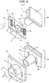
- FIG. 4 is an exploded perspective view partially illustrating a fastening portion of the housing 101 and the camera module 102 according to the first embodiment of the present invention
- FIG. 4(a) and FIG. 4(b) illustrate the fastening portion by changing the viewpoint direction.
- the camera module 102 is configured such that a cylindrical lens barrel 2 is connected to a sensor board 3 via a holder 1.
- a lens 4 is mounted on the lens barrel 2, and an imaging element 15 (not illustrated) is provided on the sensor board 3.
- the relative positions of the lens 4 and the sensor board 3 are adjusted and fixed such that an image passing through the lens 4 is appropriately focused at the center of the imaging element 15.
- the lens barrel 2 is inserted into a hole 5 provided in the housing 101, and the holder 1 is supported by two supports 6a and 6b.
- Holes 8a and 8b for applying first adhesives 7a and 7b are formed in the vicinity of the lens barrel 2 side of the supports 6a and 6b of the housing 101.
- the first adhesives 7a and 7b can be applied from a side opposite to a direction in which the holder 1 is disposed with respect to the housing 101.
- the holder 1 has grooves 9a and 9b around the lens barrel 2
- the housing 101 has projections 10a and 10b to be inserted into the grooves 9a and 9b
- second adhesives 11a and 11b are applied between the grooves 9a and 9b and the projections 10a and 10b.
- a fastening member such as a screw
- the deviation in rotational direction of the axis and the deviation in the optical axis position occur due to the pressure (fastening force of the screw).
- such a deviation can be reduced by using an adhesive as fastening means.
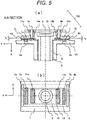
- FIG. 5(a) is a cross-sectional view of an attachment structure of the housing 101 and the holder 1 according to the first embodiment of the present invention.
- FIG. 5(b) is a plan view illustrating the holder 1, a support position, and an adhesion position according to the first embodiment of the present invention.
- the camera module 102 is fastened to the housing 101 via an adhesive as fastening means.
- the camera module 102 is configured such that the cylindrical lens barrel 2 is connected to the sensor board 3 via the holder 1.
- the lens 4 is mounted on the lens barrel 2, the imaging element 15 is provided on the sensor board 3, and the relative positions of the lens 4 and the sensor board 3 are adjusted and fixed such that an image passing through the lens 4 is appropriately focused at the center of the imaging element 15.
- the lens barrel 2 is inserted into the hole 5 provided in the housing 101, and the holder 1 is supported by the two supports 6a and 6b.
- the holes 8a and 8b for applying the first adhesives 7a and 7b are formed in the vicinity of the lens barrel 2 side of the supports 6a and 6b of the housing 101, and the first adhesives 7a and 7b can be applied from the side opposite to the direction in which the holder 1 is disposed with respect to the housing 101.
- the holder 1 has the grooves 9a and 9b around the lens barrel 2
- the housing 101 has the projections 10a and 10b to be inserted into the grooves 9a and 9b
- the second adhesives 11a and 11b are applied between the grooves 9a and 9b and the projections 10a and 10b.
- a thermosetting adhesive is easy to secure performance (adhesive force) for strengthening the fixation between the housing 101 and the holder 1, but since it takes time until the adhesive is cured, two types of adhesives are used such that the first adhesives 7a and 7b are used for temporary fixing, and the second adhesives 11a and 11b are used for main fixing.
- the first adhesives 7a and 7b have a function of holding the positional relationship between the housing 101 and the holder 1 until the second adhesives 11a and 11b are cured, and by using ultraviolet curable adhesives as the first adhesives 7a and 7b, the first adhesives 7a and 7b can be quickly cured by irradiating the adhesives with ultraviolet rays through the holes 8a and 8b of the housing 101 after adjustment. Thereafter, the thermosetting second adhesives 11a and 11b are used as an adhesive and cured in a thermostatic chamber or the like.
- a first bonding region 13 surrounded by the first adhesives 7a and 7b is closer to the lens barrel 2 side than a support region 12 surrounded by the supports 6a and 6b, and a second bonding region 14 surrounded by the second adhesives 11a and 11b is closer to the lens barrel 2 side than the first bonding region 13.
- the lens barrel 2 has a small tilt
- a lens tilt optical axis misalignment
- the shape of the supports 6a and 6b can be freely set, such as a trapezoidal shape, a semicircular shape, or a slope.
- the first adhesives 7a and 7b may be an adhesive having a short curing time such as a pressure sensitive type
- the second adhesives 11a and 11b may be a thermosetting type or a moisture curing type.
- the housing 101 is placed with the holder 1 facing down, the second adhesives 11a and 11b are applied to the grooves 9a and 9b provided in the holder 1, the projections 10a and 10b of the housing 101 are inserted to the grooves such that portions of gaps t a and t b between the bottoms of the grooves 9a and 9b and the projections 10a and 10b, which are thin portions of the adhesive layer, are accurately assembled, and thereby it becomes possible to increase and stabilize the adhesive force between the camera module 102 and the housing 101.
- the lens barrel 2 is configured not to be tilted due to a defect.
- the reason why the lens tilt is small will be described with reference to FIG. 6 .
- FIG. 6(a) is a schematic view of the deformation by the first adhesives 7a and 7b according to the first embodiment of the present invention
- FIG. 6(b) is a schematic view of the deformation by the second adhesives 11a and 11b according to the first embodiment of the present invention.
- the holder 1 In the holder 1 supported by the supports 6a and 6b, the holder 1 is deformed by a force F 1 by the first adhesives 7a and 7b. Further, the holder 1 is deformed by a force F 2 by the second adhesives 11a and 11b.
- the contact between the holder 1 and the housing 101 becomes almost the same, and even if the force F 1 by the first adhesives 7a and 7b or the force F 2 by the second adhesives 11a and 11b changes, the displacement ⁇ z in the z direction in the drawing is changed but the tilt of the lens is small.
- the force F 1 and the force F 2 are a force due to expansion or contraction of the component by the change in ambient temperature, or a force due to swelling by humidity or curing shrinkage of the adhesive.
- the lens is configured not to be tilted with respect to the environmental changes.
- the lens tilt optical axis misalignment
- a stereo-camera is obtained in which the lens tilt can be reduced with respect to the changes in the environment such as the ambient temperature, and the optical axis misalignment can be reduced.
- the distance measurement can be realized stably and accurately.
- the first adhesives 7a and 7b are for temporary fixing, the first adhesives 7a and 7b are preferably close to the supports 6a and 6b in order to reduce the deformation of the holder 1 at the time of curing shrinkage of the adhesive.
- L 1 ⁇ L 2 in FIG. 6 it is possible to reduce the deformation at the time of curing shrinkage of the first adhesives 7a and 7b.
- the second bonding region 24 may be closer to the lens barrel 14 side than the first bonding region 23.
- FIG. 7 is an exploded perspective view partially illustrating a fastening portion of the housing 101 and a camera module 106 according to the second embodiment of the present invention
- FIG. 7(a) and FIG. 7(b) illustrate the fastening portion by changing the viewpoint direction.
- the camera module 106 is configured such that a cylindrical lens barrel 22 is connected to the sensor board 3 via a holder 21.
- the lens 4 is mounted on the lens barrel 22, and the imaging element 15 (not illustrated) is provided on the sensor board 3.
- the relative positions of the lens 4 and the sensor board 3 are adjusted and fixed such that an image passing through the lens 4 is appropriately focused at the center of the imaging element 15.
- the lens barrel 2 is inserted into the hole 5 formed in the housing 101, and the holder 21 is supported by three supports 24a, 24b, and 24c.
- Holes 25a, 25b, and 25c for applying first adhesives 26a, 26b, and 26c are formed in the vicinity of the lens barrel 22 side of the supports 24a, 24b, and 24c of the housing 101, and the first adhesives 26a, 26b, and 26c can be applied from a side opposite to a direction in which the holder 1 is disposed with respect to the housing 101.
- the holder 21 has grooves 27a and 27 around the lens barrel 22, the housing 101 has projections 28a and 28b to be inserted into the grooves 27a and 27b, and second adhesives 29a and 29b (not illustrated) are applied between the grooves 27a and 27b and the projections 28a and 28b.
- FIG. 8 is a plan view illustrating the holder 21, a support position, and an adhesion position according to the second embodiment of the present invention.
- the holder 21 can be stably supported by evenly disposing the supports 24a, 24b, and 24c at at least three locations around the lens barrel 22.
- a first bonding region 31 surrounded by at least three locations of the first adhesives 26a, 26b, and 26c is closer to the lens barrel 22 side than a support region 30 surrounded by the supports 24a, 24b, and 24c, and a second bonding region 32 surrounded by the second adhesives 29a and 29b is closer to the lens barrel 22 side than the first bonding region 31.
- the support of the holder 21 can be stably performed and the fixation of the second adhesives 29a and 29b can be stabilized.
- a structure is obtained in which the lens barrel 22 has a small tilt, in other words, a lens tilt (optical axis misalignment) is small with respect to environmental changes such as a deformation due to expansion or contraction of the component by the change in ambient temperature, or a deformation due to swelling by humidity or curing shrinkage of the adhesive.
- the deformation of the holder 21 by the first adhesives 26a, 26b, and 26c and the deformation of the holder 21 by the second adhesives 29a and 29b can be made in the same direction, the contact between the holder 21 and the housing 101 becomes almost the same, and thereby a structure in which a lens tilt (optical axis misalignment) is small is obtained.
- this stereo-camera 100 the distance measurement or the like can be realized stably and accurately.
- the shapes 26a, 26b, and 26c of the first adhesives and the shapes of the second adhesives 29a and 29b may be any shape such as a cylindrical shape, a rectangular solid, or a fan shape.
- the lens barrel 22 can be stably attached to a body tube by disposing the shapes of the second adhesives 29a and 29b in a band shape circumferentially around the lens barrel 22.
- a bonding area of the second adhesives 29a and 29b to be greater than a bonding area of the first adhesives 26a, 26b, and 26c and increasing the adhesive force of the second adhesives 29a and 29b, the fixation between the housing 101 and the holder 21 can be strengthened, and thereby the stereo-camera 100 capable of performing measurement stably and accurately can be realized.
- FIG. 9 is a plan view illustrating a holder 34, a support position, and an adhesion position according to a third embodiment of the present invention.
- the holder 33 can be stably supported by evenly disposing supports 35a, 35b, and 35c at three locations around a lens barrel 34.
- a first bonding region 39 surrounded by three locations of first adhesives 36a, 36b, and 36c is closer to the lens barrel 34 side than a support region 38 surrounded by the supports 35a, 35b, and 35c, and a second bonding region 40 surrounded by at least three locations of second adhesives 37a, 37b, and 37c is closer to the lens barrel 34 side than the first bonding region 39.
- the support of the surface of the holder 33 becomes even, and the holder 33 can be stably fixed.
- the first adhesives 36a, 36b, and 36c and the second adhesives 37a, 37b, and 37c are disposed around the lens barrel 34 such that there is no overlapping portion in the circumferential direction, the holder 41 can be evenly fixed without interference by an adhesive application device when the camera module 106 is fixed.
- a structure is obtained in which the lens barrel 34 has a small tilt, in other words, a lens tilt (optical axis misalignment) is small with respect to environmental changes such as a deformation due to expansion or contraction of the component by the change in ambient temperature, or a deformation due to swelling by humidity or curing shrinkage of the adhesive.
- the deformation of the holder 33 by the first adhesives 36a, 36b, and 36c and the deformation of the holder 33 by the second adhesives 37a, 37b, and 37c can be made in the same direction, the contact between the holder 33 and the housing 101 becomes almost the same, and thereby a structure in which a lens tilt (optical axis misalignment) is small is obtained.
- this stereo-camera 100 the distance measurement or the like can be realized stably and accurately.
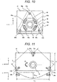
- FIG. 10 is a plan view illustrating a holder 41, a support position, and an adhesion position according to a fourth embodiment of the present invention.
- the holder 41 can be stably supported by evenly disposing supports 43a, 43b, and 43c at three locations around a lens barrel 42.
- a first bonding region 47 surrounded by three locations of first adhesives 44a, 44b, and 44c is closer to the lens barrel 42 side than a support region 46 surrounded by the supports 43a, 43b, and 43c, and a second bonding region 48 surrounded by four locations of second adhesives 45a, 45b, 45c, and 45d is closer to the lens barrel 42 side than the first bonding region 47.
- the deformation of the holder 41 by the second adhesives 45a, 45b, 45c, and 45d can be dispersed by providing the second adhesives 45a, 45b, 45c, and 45d at four locations, the stress applied to the end faces of the second adhesives 45a, 45b, 45c, and 45d can be reduced by reducing a bonding area per location, and the holder 41 can be stably fixed.
- the number of divisions of the second adhesives 45a, 45b, 45c, and 45d can be arbitrarily set.
- a structure is obtained in which the lens barrel 42 has a small tilt, in other words, a lens tilt (optical axis misalignment) is small with respect to environmental changes such as a deformation due to expansion or contraction of the component by the change in ambient temperature, or a deformation due to swelling by humidity or curing shrinkage of the adhesive.
- the deformation of the holder 41 by the first adhesives 44a, 44b, and 44c and the deformation of the holder 41 by the second adhesives 45a, 45b, 45c, and 45d can be made in the same direction, the contact between the holder 41 and the housing 101 becomes almost the same, and thereby a structure in which a lens tilt (optical axis misalignment) is small is obtained.
- this stereo-camera 100 the distance measurement or the like can be realized stably and accurately.
- FIG. 11 is a plan view for describing a problem associated with a holder 51, a support position, and an adhesion position according to a fifth embodiment of the present invention, and a schematic view of a deformation.
- Reduction in size and thickness of the stereo-camera 100 may be obtained by changing the positions of supports 53a, 53b, and 53c, and disposing the supports 53a, 53b, and 53c to avoid a lens barrel 52.
- An example of disposition of the supports 53a, 53b, and 53c corresponding to the reduction in size and thickness of the stereo-camera 100 is illustrated in FIG. 11 .
- a height H of the holder can be reduced, and thus it is possible to realize reduction in thickness of a camera module 107 and reduction in size and thickness of the stereo-camera 100.
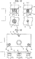
- FIG. 12 is a cross-sectional view and a plan view partially illustrating an adhesive structure.
- FIG. 12(a) is a view illustrating a case where an area exposed to air (hereinafter, referred to as an "exposed area") with respect to a volume of the adhesive 56 is large
- FIG. 12(b) is a view illustrating a case where an area exposed to air with respect to a volume of the adhesive 59 is small.
- the portion exposed to air is deformed to absorb the volume change of the contraction or the expansion of the adhesive 56.
- a force 57 (pressure) applied to the adhesive 56 is decreased, and a force on a holder 55 is also decreased.
- a force 57 (pressure) applied to the adhesive 56 is decreased, and a force on a holder 55 is also decreased.
- the portion exposed to air with respect to the volume of the adhesive 59 is small, since the portion exposed to air (exposed area) is small, the deformation of the portion exposed to air is reduced so as not to absorb all the volume change of the contraction or the expansion of the adhesive 59, a force 60 (pressure) applied to the adhesive 59 is increased, and a force on a holder 58 is increased.
- FIG. 13 is a schematic view illustrating a structure of a holder 61, supports 63a, 63b, and 63c, and first adhesives 64, 64a, and 64b according to the fifth embodiment of the present invention.
- a height of the holder can be reduced, and thus it is possible to realize reduction in thickness of the camera module 107 and reduction in size and thickness of the stereo-camera 100.
- a bonding area of the first adhesive 64 at the first position in the vicinity of the support 63a excluding the supports 63b and 63c constituting a side where the distance between the supports is long is set to be greater bonding areas of the first adhesives 65a and 65b at second and third positions in the vicinity of the other supports 63b and 63c.
- the relationship between a diameter ⁇ C of the bonding area of the first adhesive 64 at the first position, and diameters ⁇ D a and ⁇ D b of the bonding areas of the first adhesives 65a and 65c at the second and third positions in the vicinity of the other supports 63b and 63c is ⁇ C> ⁇ D a , ⁇ D b .
- FIG. 14 is a cross-sectional view and a plan view partially illustrating an adhesive structure according to a sixth embodiment of the present invention.
- the same effect as the difference in the bonding areas of the first adhesives 64, 65a, and 65b are also obtained by changing the amount of the adhesive. As illustrated in FIG.
- an adhesion height h a of a first adhesive 69a at the first position in the vicinity of the support 63a excluding the supports 68b and 63c constituting a side where the distance between the supports is long is set to be greater than adhesion heights h b and h c of first adhesives 69b and 69c at second and third positions in the vicinity of the other supports 68b and 68c (h a >h b , h c ).
- the amounts of the first adhesives 69a, 69b, and 69c are set such that the bonding areas thereof are the same and the heights h a , h b , and h c of the adhesives are different, the adhesive force of each position of the first adhesives 69a, 69b, and 69c can be made uniform, and a holder 66 can be attached uniformly and stably.
- the force applied to the holder 66 from the first adhesive 69a at the first position is increased, and thereby a force to tilt a lens barrel 67 in a direction opposite to the tilt of the lens barrel 67 by the unbalance of the supports 68a, 68b, and 68c is generated.
- the lens barrel 67 has a small tilt, in other words, a lens tilt (optical axis misalignment) is small, and thus it is possible to realize reduction in thickness of the camera module 107 and reduction in size and thickness of the stereo-camera 100. Since this effect is caused by the size of the area exposed to air with respect to the volume of the adhesive, any case which causes a difference in the area exposed to air with respect to the volume of the adhesive, such as difference in amount or shape of the adhesive may be used. By using this stereo-camera 100, the distance measurement or the like can be realized stably and accurately.
- FIG. 15 is a plan view partially illustrating an adhesive structure according to a seventh embodiment of the present invention.
- the same effect as the difference in the bonding areas of the first adhesives 64, 65a, and 65b are also obtained by changing the adhesion positions of second adhesives 74a and 74b.
- second adhesives 74a and 74b are disposed in the vicinity of the support 72a excluding the supports 72b and 72c constituting a side where the distance between the supports is long, to be close to a lens barrel 71.
- a force applied to a holder 70 from the second adhesives 74a and 74b is increased, and thereby a force to tilt the lens barrel 71 in a direction opposite to the tilt of the lens barrel 71 by the unbalance of the supports 72a, 72b, and 72c and the first adhesives 73a, 73b, and 73c is generated.
- a structure is obtained in which the lens barrel 71 has a small tilt, in other words, a lens tilt (optical axis misalignment) is small, and thus it is possible to realize reduction in thickness of the camera module 107 and reduction in size and thickness of the stereo-camera 100.
- this stereo-camera 100 the distance measurement or the like can be realized stably and accurately.
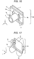
- FIG. 16 is a perspective view of a camera module 108 according to an eighth embodiment of the present invention.
- the tilt of the lens barrel 52 depending on the positions of the supports 53a, 53b, and 53c and the positions of the first adhesives 54a, 54b, 54c illustrated in FIG. 11 is caused by the deformation of the holder 51 when the rigidity of the holder 51 is uniform. Accordingly, if in a holder 75, the rigidity of a portion between a second support and a third support where the distance between the supports is large and the deformation of the holder 75 is large is increased, it is possible to reduce the tilt of a lens barrel 76.
- FIG. 16 illustrates a shape in which a projection 77 for increasing the rigidity of the holder is provided.
- the projection 77 of the holder 75 can be obtained by increasing the plate thickness of the holder 75, providing a rib, or attaching a separated member so as to increase the rigidity of the holder 75.
- FIG. 17 is a perspective view of a camera module 109 according to a ninth embodiment of the present invention.
- the first adhesives 7a and 7b can be replaced with a jig without using the adhesives 7a and 7b for temporary fixing illustrated in FIG. 4 .
- a projection 80 for holding the camera module 109 from the support (not illustrated) to a lens barrel 79 side is provided to a holder 78.
- a second adhesive (not illustrated) is disposed closer to the lens barrel side than the projections 80.
- a notch 81 is provided on the projection 80 of the holder 78 toward the lens barrel 79 in order to position and hold the camera module 109 from the outside, and thereby a structure capable of positioning is obtained.
- the line connecting the notches 81 passes through the center of the lens 4.
- a structure capable of reducing the lens tilt at the time of adjustment is obtained. Since the projection 80 is a structure for holding the holder 78, the projection 80 may be a cylinder, a rectangular parallelepiped, a hole, or the like.
- the projections 80 for holding the holder 78, and the supports a structure is obtained in which the lens barrel 79 has a small tilt, in other words, a tilt of the lens 4 (optical axis misalignment) is small.
- this stereo-camera 100 the distance measurement or the like can be realized stably and accurately.
- an imaging element module including a lens barrel and a holder on an outer periphery of the lens barrel; and a housing configured to hold the imaging element module.
- the housing includes a support configured to support the holder of the imaging element module, the holder is held by the housing via a first bonding region between the support and the lens barrel, and a second bonding region located closer to the lens barrel than the first bonding region.
- the second bonding region is disposed in a band shape on the outer periphery of the lens barrel.
- the holder includes a groove
- the housing includes a projection
- the projection is configured to be inserted into the groove
- the second bonding region is located between the groove and the projection.
- a hole is formed in the housing, and a first adhesive is applied to the first bonding region through the hole.
- the support is provided at three locations, an application portion for a first adhesive is provided at three locations of the first bonding region, and an application portion for a second adhesive is provided at three locations of the second bonding region.
- first adhesive and the second adhesive are disposed not to overlap in a circumferential direction around the lens barrel.
- the support is provided at three locations, an application portion for a first adhesive is provided at three locations of the first bonding region, an application portion for a second adhesive is provided at three locations of the second bonding region, and areas which are exposed to air, of the first adhesive in a vicinity of the supports constituting a longest distance among distances between the supports at the three locations are greater than an area which is exposed to air, of the first adhesive in a vicinity of the other support.
- the support is provided at three locations, an application portion for a first adhesive is provided at three locations of the first bonding region, an application portion for a second adhesive is provided at three locations of the second bonding region, and application heights of the first adhesive in a vicinity of the supports constituting a longest distance among distances between the supports at the three locations are lower than an application height of the first adhesive in a vicinity of the other support.
- the support is provided at three locations, an application portion for a first adhesive is provided at three locations of the first bonding region, an application portion for a second adhesive is provided at three locations of the second bonding region, and amounts of the first adhesive in a vicinity of the supports constituting a longest distance among distances between the supports at the three locations are greater than an amount of the first adhesive in a vicinity of the other support.
- the support is provided at three locations, an application portion for a first adhesive is provided at three locations of the first bonding region, an application portion for a second adhesive is provided at three locations of the second bonding region, and the second adhesive is disposed in a vicinity of the supports constituting a longest distance among distances between the supports at the three locations to be close to the lens barrel.
- the support is provided at three locations, an application portion for a first adhesive is provided at three locations of the first bonding region, an application portion for a second adhesive is provided at three locations of the second bonding region, and the projection is provided to the holder with respect to the supports constituting a longest distance among distances between the supports at the three locations.
- an imaging element module including a lens barrel and a holder on an outer periphery of the lens barrel; and a housing configured to hold the imaging element module.
- the housing includes a support configured to support the holder of the imaging element module, and the holder is held by the housing via a first press region surrounded by projections configured to hold the holder and be provided between the lens barrel and the supports, and a second bonding region located closer to the lens barrel than the first press region.
Landscapes
- Physics & Mathematics (AREA)
- General Physics & Mathematics (AREA)
- Optics & Photonics (AREA)
- Engineering & Computer Science (AREA)
- Multimedia (AREA)
- Signal Processing (AREA)
- Studio Devices (AREA)
- Lens Barrels (AREA)
- Stereoscopic And Panoramic Photography (AREA)
- Camera Bodies And Camera Details Or Accessories (AREA)
Abstract
Description
- The present invention relates to an imaging device.
- In recent years, a driving support system in which an imaging device is mounted on a vehicle, and information for safe traveling is provided to a driver based on ambient environment data at the time of vehicle traveling, acquired by the imaging device, or vehicle control is automatically performed based on the information has been proposed. As the imaging device described above, for example, a stereo-camera device is known, and, for example, a vehicle, a pedestrian, and an obstacle in front of the vehicle are recognized by a pair of imaging elements installed on left and right sides and the imaging device is used for an application such as automatic braking. Therefore, it is necessary to reliably measure a distance from an object.
- In the stereo-camera device, a process of extracting a feature point common to a pair of images from information on the images and of calculating the number of pixels in which the position of the feature point is shifted between the pair of images is performed by an integrated circuit, and the distance is calculated. Therefore, if there is a deviation other than the original parallax between the pair of images, an error occurs in the result of distance measurement. Therefore, it is common practice to adjust the optical axes of two cameras with high precision so as to minimize the deviation, or to correct the deviation in the process performed by the integrated circuit.
- In the imaging device, when fixing a housing and an imaging element module, in general, fixing is performed by fastening a fixing member while correction of the deviation or the like in the position of the optical axis of the imaging element module, and the rotational direction of the axis is performed by confirming actual images.
PTL 1 discloses that a camera module (imaging element module) is attached to a housing by a screw. - PTL 1:
JP 2016-208125 A - When the camera module is attached to the housing by a fastening member such as a screw as in the related art, the fastening force of the fastening member is transmitted to the pressurized camera module, which may cause the deviation in rotational direction of the axis and the deviation in the optical axis position at the time of fastening. Therefore, it is difficult to adjust the position of the optical axis with high accuracy, and to eliminate the positional deviation due to the friction between the housing and the imaging element module at the time of fastening.
- In addition, when a fastening portion is fastened by a screw or the like, bending is suppressed by the frictional force between a bearing surface of the screw and a holder of the camera module, but there is a possibility that a large thermal stress is generated against temperature change due to ambient temperature or the like, and the fastening portion may slip. The slippage does not always occur stably, and the reproducibility of the deformed shape with respect to temperature change is poor. For this reason, deterioration of reproducibility and drift of the optical axis misalignment and the parallax deviation are caused in the left and right camera modules, and there is a problem of occurrence of an error in the distance measurement which is difficult to correct.
- The purpose of the present invention is to provide an imaging device capable of reducing optical axis misalignment from, for instance, thermal deformations due to the differences in thermal expansion at ambient temperature between a housing and an imaging element module.
- In order to solve the above-described problem, one of the representative imaging devices of the present invention includes, as a camera module, an imaging element module including a lens barrel and a holder on an outer periphery of the lens barrel; and a housing configured to hold the imaging element module. The housing includes a support configured to support the holder of the imaging element module, the holder is held by the housing via a first bonding region between the support and the lens barrel, and a second bonding region located closer to the lens barrel than the first bonding region.
- According to the present invention, there is provided an imaging device capable of reducing optical axis misalignment from thermal deformations due to the differences in thermal expansion at ambient temperature or the like between a housing and an imaging element module.
- Problems, configurations, and effects other than the above are clarified by the following description of the embodiments.
-
- [
FIG. 1] FIG. 1 is a configuration diagram of a stereo-camera according to a first embodiment of the present invention.FIG. 1(a) is a perspective view of a front surface side and an upper surface side, andFIG. 1(b) is a perspective view of a rear surface side and a lower surface side. - [
FIG. 2] FIG. 2 is a plan view illustrating a state where the stereo-camera of the first embodiment of the present invention is installed in a car. - [
FIG. 3] FIG. 3 is an exploded perspective view of the stereo-camera according to the first embodiment of the present invention. - [
FIG. 4] FIG. 4 is an exploded perspective view partially illustrating a fastening portion of a housing and a camera module according to the first embodiment of the present invention.FIG. 4(a) is a perspective view seen from a rear side, andFIG. 4(b) is a perspective view seen from a front side. - [
FIG. 5] FIG. 5 is a cross-sectional view of an attachment structure of the housing and a holder according to the first embodiment of the present invention.FIG.5(a) is a cross-sectional view taken along line A-A ofFIG. 4(b) , andFIG. 5(b) is a plan view ofFIG. 5(a) . - [
FIG. 6] FIG. 6 is a schematic view of a deformation by a first adhesive and a schematic view of a deformation by a second adhesive according to the first embodiment of the present invention,FIG. 6(a) is a schematic view of the deformation by the first adhesive, andFIG. 6(b) is a schematic view of the deformation by the second adhesive. - [
FIG. 7] FIG. 7 is an exploded perspective view partially illustrating a fastening portion of a housing and a camera module according to a second embodiment of the present invention.FIG. 7(a) is a perspective view seen from a rear side, andFIG. 7(b) is a perspective view seen from a front side. - [
FIG. 8] FIG. 8 is a plan view illustrating a holder, a support position, and an adhesion position according to the second embodiment of the present invention. - [
FIG. 9] FIG. 9 is a plan view illustrating a holder, a support position, and an adhesion position according to a third embodiment of the present invention. - [
FIG. 10] FIG. 10 is a plan view illustrating a holder, a support position, and an adhesion position according to a fourth embodiment of the present invention. - [
FIG. 11] FIG. 11 is a plan view for describing a problem associated with a holder, a support position, and an adhesion position according to a fifth embodiment of the present invention, and a schematic view of a deformation. - [
FIG. 12] FIG. 12 is a cross-sectional view and a plan view partially illustrating an adhesive structure.FIG. 12(a) is a view illustrating a case where an area exposed to air with respect to the volume of the adhesive is large, andFIG. 12(b) is a view illustrating a case where an area exposed to air with respect to the volume of the adhesive is small. - [
FIG. 13] FIG. 13 is a schematic view illustrating a structure of the holder, a support, and a first adhesive according to the fifth embodiment of the present invention. - [
FIG. 14] FIG. 14 is a cross-sectional view and a plan view partially illustrating an adhesive structure according to a sixth embodiment of the present invention. - [
FIG. 15] FIG. 15 is a plan view partially illustrating an adhesive structure according to a seventh embodiment of the present invention. - [
FIG. 16] FIG. 16 is a perspective view of acamera module 108 according to an eighth embodiment of the present invention. - [
FIG. 17] FIG. 17 is a perspective view of acamera module 109 according to a ninth embodiment of the present invention. - Hereinafter, embodiments of the present invention will be described with reference to the drawings. In addition, since configurations assigned with the same reference numeral have the same function, unless otherwise stated, the description of the configuration already described is omitted.
- In addition, in the necessary drawings, orthogonal coordinate axes consisting of an x-axis, a y-axis, and a z-axis are described in order to clarify the description of the position of each part.
- An example of a stereo-
camera 100 of the present embodiment will be described.FIGS. 1(a) and 1(b) are configuration diagrams of the stereo-camera 100 according to a first embodiment of the present invention.FIG. 1(a) illustrates a diagram seen from a front surface side and an upper surface side of the stereo-camera 100, andFIG. 1(b) illustrates a diagram seen from a rear surface side and a lower surface side. The stereo-camera 100 according to the present embodiment has a structure in which a pair of camera modules (imaging element modules) 102 are attached to both ends of ahousing 101, and acover 103 covering the rear surface and the lower surface is attached to thehousing 101 using a screw or the like. Electrical connection to the stereo-camera 100 is made by connecting wiring to an internalelectrical connector 104 via an opening on the rear surface of thecover 103. A distance to an object can be obtained by imaging a front surface side of the stereo-camera 100 by the pair ofcamera modules 102 and obtaining the parallax of the object from the pair of images. Hereinafter, although the stereo-camera 100 is described as an example, it is not limited to the stereo-camera 100, and, unless otherwise stated, in the present embodiment and other embodiments, the imaging device including at least one camera module such as a monocular camera is included. -
FIG. 2 is a plan view illustrating a state where the stereo-camera 100 of the first embodiment of the present invention is installed in a car. Thecamera module 102 is installed to be close to aninclined windshield 110, and can recognize the object appearing in a visual field region surrounded by a broken line. As illustrated inFIGS. 1 and2 , a left-right direction connecting the pair ofcamera modules 102 is referred to as the X-axis, a front-rear direction that is an optical axis direction of thecamera module 102 is referred to as the Z-axis, and an up-down direction perpendicular to the X-axis and the Z-axis is referred to as the Y-axis. -
FIG. 3 is an exploded perspective view of the stereo-camera 100 according to the first embodiment of the present invention. The pair of left andright camera modules 102 are fastened to the left and right of thehousing 101 via an adhesive (not illustrated) as fastening means. In addition, acircuit board 105 in which a signal processing circuit is formed is provided in thehousing 101, and is wired to the outside via theelectrical connector 104 mounted on thecircuit board 105. -
FIG. 4 is an exploded perspective view partially illustrating a fastening portion of thehousing 101 and thecamera module 102 according to the first embodiment of the present invention,FIG. 4(a) and FIG. 4(b) illustrate the fastening portion by changing the viewpoint direction. Thecamera module 102 is configured such that acylindrical lens barrel 2 is connected to asensor board 3 via aholder 1. Alens 4 is mounted on thelens barrel 2, and an imaging element 15 (not illustrated) is provided on thesensor board 3. The relative positions of thelens 4 and thesensor board 3 are adjusted and fixed such that an image passing through thelens 4 is appropriately focused at the center of theimaging element 15. - In the
camera module 102, thelens barrel 2 is inserted into ahole 5 provided in thehousing 101, and theholder 1 is supported by twosupports Holes first adhesives lens barrel 2 side of thesupports housing 101. Thefirst adhesives holder 1 is disposed with respect to thehousing 101. In addition, theholder 1 hasgrooves lens barrel 2, thehousing 101 hasprojections grooves second adhesives grooves projections camera module 102 including theholder 1 is fixed to thehousing 101, the deviation in rotational direction of the axis and the deviation in the optical axis position occur due to the pressure (fastening force of the screw). In the present embodiment, such a deviation can be reduced by using an adhesive as fastening means. - Here, the concept of the present embodiment for changes in the environment such as ambient temperature and humidity will be described using
FIG. 5 andFIG 6 .FIG. 5(a) is a cross-sectional view of an attachment structure of thehousing 101 and theholder 1 according to the first embodiment of the present invention.FIG. 5(b) is a plan view illustrating theholder 1, a support position, and an adhesion position according to the first embodiment of the present invention. Thecamera module 102 is fastened to thehousing 101 via an adhesive as fastening means. Thecamera module 102 is configured such that thecylindrical lens barrel 2 is connected to thesensor board 3 via theholder 1. Thelens 4 is mounted on thelens barrel 2, theimaging element 15 is provided on thesensor board 3, and the relative positions of thelens 4 and thesensor board 3 are adjusted and fixed such that an image passing through thelens 4 is appropriately focused at the center of theimaging element 15. - In the
camera module 102, thelens barrel 2 is inserted into thehole 5 provided in thehousing 101, and theholder 1 is supported by the twosupports holes first adhesives lens barrel 2 side of thesupports housing 101, and thefirst adhesives holder 1 is disposed with respect to thehousing 101. In addition, theholder 1 has thegrooves lens barrel 2, thehousing 101 has theprojections grooves second adhesives grooves projections housing 101 and theholder 1, but since it takes time until the adhesive is cured, two types of adhesives are used such that thefirst adhesives second adhesives first adhesives housing 101 and theholder 1 until thesecond adhesives first adhesives first adhesives holes housing 101 after adjustment. Thereafter, the thermosettingsecond adhesives - At this time, as illustrated in
FIG. 5(b) , afirst bonding region 13 surrounded by thefirst adhesives lens barrel 2 side than asupport region 12 surrounded by thesupports second bonding region 14 surrounded by thesecond adhesives lens barrel 2 side than thefirst bonding region 13. By satisfying the conditions of thesupport region 12, thefirst bonding region 13, and thesecond bonding region 14, a structure is obtained in which thelens barrel 2 has a small tilt, in other words, a lens tilt (optical axis misalignment) is small with respect to environmental changes such as a deformation due to expansion or contraction of the component by the change in ambient temperature, or a deformation due to swelling by humidity or curing shrinkage of the adhesive. Here, the shape of thesupports first adhesives second adhesives - Further, the
housing 101 is placed with theholder 1 facing down, thesecond adhesives grooves holder 1, theprojections housing 101 are inserted to the grooves such that portions of gaps ta and tb between the bottoms of thegrooves projections camera module 102 and thehousing 101. Further, by providing thegrooves second adhesives hole 5 of the housing and thelens barrel 2 of the holder, and thus thelens barrel 2 is configured not to be tilted due to a defect. The reason why the lens tilt is small will be described with reference toFIG. 6 . -
FIG. 6(a) is a schematic view of the deformation by thefirst adhesives FIG. 6(b) is a schematic view of the deformation by thesecond adhesives holder 1 supported by thesupports holder 1 is deformed by a force F1 by thefirst adhesives holder 1 is deformed by a force F2 by thesecond adhesives holder 1 by thefirst adhesives holder 1 by thesecond adhesives holder 1 and thehousing 101 becomes almost the same, and even if the force F1 by thefirst adhesives second adhesives supports first adhesives second adhesives camera 100, since the rotation of the left and right camera modules around the y-axis and the rotation of the left and right camera modules around the x-axis have a great influence on an error in the distance measurement, it is important that the lens tilt (optical axis misalignment) is small with respect to the environmental changes for improving the accuracy of the distance measurement. With this configuration, a stereo-camera is obtained in which the lens tilt can be reduced with respect to the changes in the environment such as the ambient temperature, and the optical axis misalignment can be reduced. By using this stereo-camera, the distance measurement can be realized stably and accurately. - Since the
first adhesives first adhesives supports holder 1 at the time of curing shrinkage of the adhesive. By setting L1<L2 inFIG. 6 , it is possible to reduce the deformation at the time of curing shrinkage of thefirst adhesives lens barrel 14 side than thefirst bonding region 23. - As before, a second embodiment will be described using
FIG. 7 andFIG. 8 .FIG. 7 is an exploded perspective view partially illustrating a fastening portion of thehousing 101 and acamera module 106 according to the second embodiment of the present invention,FIG. 7(a) and FIG. 7(b) illustrate the fastening portion by changing the viewpoint direction. - The
camera module 106 is configured such that acylindrical lens barrel 22 is connected to thesensor board 3 via aholder 21. Thelens 4 is mounted on thelens barrel 22, and the imaging element 15 (not illustrated) is provided on thesensor board 3. The relative positions of thelens 4 and thesensor board 3 are adjusted and fixed such that an image passing through thelens 4 is appropriately focused at the center of theimaging element 15. - In the
camera module 106, thelens barrel 2 is inserted into thehole 5 formed in thehousing 101, and theholder 21 is supported by threesupports Holes first adhesives lens barrel 22 side of thesupports housing 101, and thefirst adhesives holder 1 is disposed with respect to thehousing 101. In addition, theholder 21 hasgrooves 27a and 27 around thelens barrel 22, thehousing 101 hasprojections grooves second adhesives grooves projections -
FIG. 8 is a plan view illustrating theholder 21, a support position, and an adhesion position according to the second embodiment of the present invention. Theholder 21 can be stably supported by evenly disposing thesupports lens barrel 22. Afirst bonding region 31 surrounded by at least three locations of thefirst adhesives lens barrel 22 side than asupport region 30 surrounded by thesupports second adhesives lens barrel 22 side than thefirst bonding region 31. By disposing thefirst adhesives supports holder 21 can be stably performed and the fixation of thesecond adhesives support region 30, thefirst bonding region 31, and the second bonding region 32, a structure is obtained in which thelens barrel 22 has a small tilt, in other words, a lens tilt (optical axis misalignment) is small with respect to environmental changes such as a deformation due to expansion or contraction of the component by the change in ambient temperature, or a deformation due to swelling by humidity or curing shrinkage of the adhesive. At this time, when thefirst bonding region 31 is included 2/3 or more on thelens barrel 22 side of thesupport region 30, and the second bonding region 32 is included 2/3 or more on thelens barrel 22 side of thefirst bonding region 31, the deformation of theholder 21 by thefirst adhesives holder 21 by thesecond adhesives holder 21 and thehousing 101 becomes almost the same, and thereby a structure in which a lens tilt (optical axis misalignment) is small is obtained. By using this stereo-camera 100, the distance measurement or the like can be realized stably and accurately. - Here, the
shapes second adhesives lens barrel 22 can be stably attached to a body tube by disposing the shapes of thesecond adhesives lens barrel 22. Further, by setting a bonding area of thesecond adhesives first adhesives second adhesives housing 101 and theholder 21 can be strengthened, and thereby the stereo-camera 100 capable of performing measurement stably and accurately can be realized. -
FIG. 9 is a plan view illustrating aholder 34, a support position, and an adhesion position according to a third embodiment of the present invention. - The
holder 33 can be stably supported by evenly disposingsupports lens barrel 34. Afirst bonding region 39 surrounded by three locations offirst adhesives lens barrel 34 side than asupport region 38 surrounded by thesupports second bonding region 40 surrounded by at least three locations ofsecond adhesives lens barrel 34 side than thefirst bonding region 39. By disposing thefirst adhesives supports holder 33 at the time of temporary fixing can be stably held. By providing thesecond adhesives holder 33 becomes even, and theholder 33 can be stably fixed. At this time, when thefirst adhesives second adhesives lens barrel 34 such that there is no overlapping portion in the circumferential direction, theholder 41 can be evenly fixed without interference by an adhesive application device when thecamera module 106 is fixed. By satisfying the conditions of thesupport region 38, thefirst bonding region 39, and thesecond bonding region 40, a structure is obtained in which thelens barrel 34 has a small tilt, in other words, a lens tilt (optical axis misalignment) is small with respect to environmental changes such as a deformation due to expansion or contraction of the component by the change in ambient temperature, or a deformation due to swelling by humidity or curing shrinkage of the adhesive. At this time, when thefirst bonding region 39 is included 2/3 or more on thelens barrel 34 side of thesupport region 38, and thesecond bonding region 40 is included 2/3 or more on thelens barrel 34 side of thefirst bonding region 39, the deformation of theholder 33 by thefirst adhesives holder 33 by thesecond adhesives holder 33 and thehousing 101 becomes almost the same, and thereby a structure in which a lens tilt (optical axis misalignment) is small is obtained. By using this stereo-camera 100, the distance measurement or the like can be realized stably and accurately. -
FIG. 10 is a plan view illustrating aholder 41, a support position, and an adhesion position according to a fourth embodiment of the present invention. - The
holder 41 can be stably supported by evenly disposingsupports lens barrel 42. Afirst bonding region 47 surrounded by three locations offirst adhesives lens barrel 42 side than asupport region 46 surrounded by thesupports second bonding region 48 surrounded by four locations ofsecond adhesives lens barrel 42 side than thefirst bonding region 47. By disposing thefirst adhesives supports holder 41 at the time of temporary fixing can be stably held. The deformation of theholder 41 by thesecond adhesives second adhesives second adhesives holder 41 can be stably fixed. Here, the number of divisions of thesecond adhesives - By satisfying the conditions of the
support region 46, thefirst bonding region 47, and thesecond bonding region 48, a structure is obtained in which thelens barrel 42 has a small tilt, in other words, a lens tilt (optical axis misalignment) is small with respect to environmental changes such as a deformation due to expansion or contraction of the component by the change in ambient temperature, or a deformation due to swelling by humidity or curing shrinkage of the adhesive. At this time, when thefirst bonding region 47 is included 2/3 or more on thelens barrel 42 side of thesupport region 46, and thesecond bonding region 48 is included 2/3 or more on thelens barrel 42 side of thefirst bonding region 47, the deformation of theholder 41 by thefirst adhesives holder 41 by thesecond adhesives holder 41 and thehousing 101 becomes almost the same, and thereby a structure in which a lens tilt (optical axis misalignment) is small is obtained. By using this stereo-camera 100, the distance measurement or the like can be realized stably and accurately. -
FIG. 11 is a plan view for describing a problem associated with aholder 51, a support position, and an adhesion position according to a fifth embodiment of the present invention, and a schematic view of a deformation. - Reduction in size and thickness of the stereo-
camera 100 may be obtained by changing the positions ofsupports supports lens barrel 52. An example of disposition of thesupports camera 100 is illustrated inFIG. 11 . By setting a distance L11 between thesecond support 53b and thethird support 53c, among three locations of thesupports supports lens barrel 52 in the y direction in the drawing, a height H of the holder can be reduced, and thus it is possible to realize reduction in thickness of a camera module 107 and reduction in size and thickness of the stereo-camera 100. At this time, since the distance L11 is longer than the other two distances L12 and L13, the deformation of the holder progresses, deflection with respect to the same force becomes increased, a deflection amount Δz11 is increased, and thelens barrel 52 is tilted to θx. - Here, a force received from
adhesives 56 and 59 (pressure of the adhesive) will be described with reference toFIG. 12. FIG. 12 is a cross-sectional view and a plan view partially illustrating an adhesive structure.FIG. 12(a) is a view illustrating a case where an area exposed to air (hereinafter, referred to as an "exposed area") with respect to a volume of the adhesive 56 is large, andFIG. 12(b) is a view illustrating a case where an area exposed to air with respect to a volume of the adhesive 59 is small. In a case where the area exposed to air with respect to the volume of the adhesive 56 is large, the portion exposed to air is deformed to absorb the volume change of the contraction or the expansion of the adhesive 56. Therefore, a force 57 (pressure) applied to the adhesive 56 is decreased, and a force on aholder 55 is also decreased. On the other hand, in a case where the area exposed to air with respect to the volume of the adhesive 59 is small, since the portion exposed to air (exposed area) is small, the deformation of the portion exposed to air is reduced so as not to absorb all the volume change of the contraction or the expansion of the adhesive 59, a force 60 (pressure) applied to the adhesive 59 is increased, and a force on aholder 58 is increased. - Using this principle, a structure for reducing the tilt of the
lens barrel 52 by unbalance of thesupports FIG. 13. FIG. 13 is a schematic view illustrating a structure of aholder 61, supports 63a, 63b, and 63c, andfirst adhesives 64, 64a, and 64b according to the fifth embodiment of the present invention. By setting a distance between thesecond support 63b and thethird support 63c, among three locations of thesupports supports camera 100. Among the positions of thesupports support 63a excluding thesupports first adhesives other supports FIG. 13 , the relationship between a diameter ϕC of the bonding area of the first adhesive 64 at the first position, and diameters ϕDa and ϕDb of the bonding areas of thefirst adhesives 65a and 65c at the second and third positions in the vicinity of theother supports holder 61 from the first adhesive 64 at the first position is increased, and thereby a force to tilt the lens barrel 62 in a direction opposite to the tilt of the lens barrel 62 by the unbalance of thesupports first adhesives supports camera 100. By using this stereo-camera 100, the distance measurement or the like can be realized stably and accurately. -
FIG. 14 is a cross-sectional view and a plan view partially illustrating an adhesive structure according to a sixth embodiment of the present invention. The same effect as the difference in the bonding areas of thefirst adhesives FIG. 11 , at the time of positioning supports 68a, 68b, and 68c, an adhesion height ha of afirst adhesive 69a at the first position in the vicinity of thesupport 63a excluding thesupports first adhesives other supports first adhesives first adhesives holder 66 can be attached uniformly and stably. By setting the adhesion height ha of thefirst adhesive 69a at the first position to be greater than the heights hb and hc of the other first adhesives, the force applied to theholder 66 from thefirst adhesive 69a at the first position is increased, and thereby a force to tilt alens barrel 67 in a direction opposite to the tilt of thelens barrel 67 by the unbalance of thesupports first adhesives supports lens barrel 67 has a small tilt, in other words, a lens tilt (optical axis misalignment) is small, and thus it is possible to realize reduction in thickness of the camera module 107 and reduction in size and thickness of the stereo-camera 100. Since this effect is caused by the size of the area exposed to air with respect to the volume of the adhesive, any case which causes a difference in the area exposed to air with respect to the volume of the adhesive, such as difference in amount or shape of the adhesive may be used. By using this stereo-camera 100, the distance measurement or the like can be realized stably and accurately. -
FIG. 15 is a plan view partially illustrating an adhesive structure according to a seventh embodiment of the present invention. The same effect as the difference in the bonding areas of thefirst adhesives second adhesives FIG. 15 , at the time of positioning supports 72a, 72b, and 72c,second adhesives supports lens barrel 71. A force applied to aholder 70 from thesecond adhesives lens barrel 71 in a direction opposite to the tilt of thelens barrel 71 by the unbalance of thesupports first adhesives supports first adhesives second adhesives lens barrel 71 has a small tilt, in other words, a lens tilt (optical axis misalignment) is small, and thus it is possible to realize reduction in thickness of the camera module 107 and reduction in size and thickness of the stereo-camera 100. By using this stereo-camera 100, the distance measurement or the like can be realized stably and accurately. -
FIG. 16 is a perspective view of acamera module 108 according to an eighth embodiment of the present invention. The tilt of thelens barrel 52 depending on the positions of thesupports first adhesives FIG. 11 is caused by the deformation of theholder 51 when the rigidity of theholder 51 is uniform. Accordingly, if in aholder 75, the rigidity of a portion between a second support and a third support where the distance between the supports is large and the deformation of theholder 75 is large is increased, it is possible to reduce the tilt of alens barrel 76.FIG. 16 illustrates a shape in which aprojection 77 for increasing the rigidity of the holder is provided. By providing theprojection 77 to theholder 75, a structure is obtained in which the tilt of thelens barrel 76 by the unbalance of the supports and the positions of the first adhesives is small, in other words, a structure is obtained in which a tilt of a lens 4 (optical axis misalignment) is small, and thus it is possible to realize reduction in thickness of thecamera module 108 and reduction in size and thickness of the stereo-camera 100. By using this stereo-camera 100, the distance measurement or the like can be realized stably and accurately. Theprojection 77 of theholder 75 can be obtained by increasing the plate thickness of theholder 75, providing a rib, or attaching a separated member so as to increase the rigidity of theholder 75. -
FIG. 17 is a perspective view of acamera module 109 according to a ninth embodiment of the present invention. Thefirst adhesives adhesives FIG. 4 . Here, in order to enable the use of the jig, aprojection 80 for holding thecamera module 109 from the support (not illustrated) to alens barrel 79 side is provided to aholder 78. A second adhesive (not illustrated) is disposed closer to the lens barrel side than theprojections 80. Anotch 81 is provided on theprojection 80 of theholder 78 toward thelens barrel 79 in order to position and hold thecamera module 109 from the outside, and thereby a structure capable of positioning is obtained. The line connecting thenotches 81 passes through the center of thelens 4. A structure capable of reducing the lens tilt at the time of adjustment is obtained. Since theprojection 80 is a structure for holding theholder 78, theprojection 80 may be a cylinder, a rectangular parallelepiped, a hole, or the like. - By the arrangement of the second adhesives, the
projections 80 for holding theholder 78, and the supports, a structure is obtained in which thelens barrel 79 has a small tilt, in other words, a tilt of the lens 4 (optical axis misalignment) is small. By using this stereo-camera 100, the distance measurement or the like can be realized stably and accurately. - The embodiments described above can be expressed as follows.
- There are provided an imaging element module including a lens barrel and a holder on an outer periphery of the lens barrel; and a housing configured to hold the imaging element module. The housing includes a support configured to support the holder of the imaging element module, the holder is held by the housing via a first bonding region between the support and the lens barrel, and a second bonding region located closer to the lens barrel than the first bonding region.
- In addition, the second bonding region is disposed in a band shape on the outer periphery of the lens barrel.
- In addition, the holder includes a groove, the housing includes a projection, the projection is configured to be inserted into the groove, and the second bonding region is located between the groove and the projection.
- In addition, a hole is formed in the housing, and a first adhesive is applied to the first bonding region through the hole.
- In addition, the support is provided at three locations, an application portion for a first adhesive is provided at three locations of the first bonding region, and an application portion for a second adhesive is provided at three locations of the second bonding region.
- In addition, the first adhesive and the second adhesive are disposed not to overlap in a circumferential direction around the lens barrel.
- In addition, the support is provided at three locations, an application portion for a first adhesive is provided at three locations of the first bonding region, an application portion for a second adhesive is provided at three locations of the second bonding region, and areas which are exposed to air, of the first adhesive in a vicinity of the supports constituting a longest distance among distances between the supports at the three locations are greater than an area which is exposed to air, of the first adhesive in a vicinity of the other support.
- In addition, the support is provided at three locations, an application portion for a first adhesive is provided at three locations of the first bonding region, an application portion for a second adhesive is provided at three locations of the second bonding region, and application heights of the first adhesive in a vicinity of the supports constituting a longest distance among distances between the supports at the three locations are lower than an application height of the first adhesive in a vicinity of the other support.
- In addition, the support is provided at three locations, an application portion for a first adhesive is provided at three locations of the first bonding region, an application portion for a second adhesive is provided at three locations of the second bonding region, and amounts of the first adhesive in a vicinity of the supports constituting a longest distance among distances between the supports at the three locations are greater than an amount of the first adhesive in a vicinity of the other support.
- In addition, the support is provided at three locations, an application portion for a first adhesive is provided at three locations of the first bonding region, an application portion for a second adhesive is provided at three locations of the second bonding region, and the second adhesive is disposed in a vicinity of the supports constituting a longest distance among distances between the supports at the three locations to be close to the lens barrel.
- In addition, the support is provided at three locations, an application portion for a first adhesive is provided at three locations of the first bonding region, an application portion for a second adhesive is provided at three locations of the second bonding region, and the projection is provided to the holder with respect to the supports constituting a longest distance among distances between the supports at the three locations.
- There are provided an imaging element module including a lens barrel and a holder on an outer periphery of the lens barrel; and a housing configured to hold the imaging element module. The housing includes a support configured to support the holder of the imaging element module, and the holder is held by the housing via a first press region surrounded by projections configured to hold the holder and be provided between the lens barrel and the supports, and a second bonding region located closer to the lens barrel than the first press region.
- The respective embodiments described above are described in detail in order to describe the present invention for easy understanding, and are not necessarily limited to those having all the described configurations. In addition, it is possible to replace part of the configuration of a certain embodiment with part of the configuration of other embodiments, and further to add part or all of the configurations of other embodiments to the configuration of a certain embodiment.
-
- 1
- holder
- 2
- lens barrel
- 3
- sensor board
- 4
- lens
- 5
- hole
- 6,
- 6a, 6b support
- 7
- first adhesive
- 8
- hole
- 9
- groove
- 10
- projection
- 11
- second adhesive
- 12
- support region
- 13
- first bonding region
- 14
- second bonding region
- 15
- imaging element
- 55
- holder
- 56
- adhesive
- 57
- force
- 77
- projection
- 80
- projection
- 81
- notch
- 100
- stereo-camera
- 101
- housing
- 102
- camera module (imaging element module)
- 103
- cover
- 104
- connector
- 105
- circuit board
- 106
- camera module
- 107
- camera module
- 108
- camera module
- 109
- camera module
- 110
- windshield
Claims (12)
- An imaging device comprising:an imaging element module including a lens barrel and a holder on an outer periphery of the lens barrel; and a housing configured to hold the imaging element module,wherein the housing includes a support configured to support the holder of the imaging element module, andthe holder is held by the housing via a first bonding region between the support and the lens barrel, and a second bonding region located closer to the lens barrel than the first bonding region.
- The imaging device according to claim 1,
wherein the second bonding region is disposed in a band shape on the outer periphery of the lens barrel. - The imaging device according to claim 1,
wherein the holder includes a groove, the housing includes a projection, and the projection is configured to be inserted into the groove, and
the second bonding region is located between the groove and the projection. - The imaging device according to claim 1,
wherein a hole is formed in the housing, and a first adhesive is applied to the first bonding region through the hole. - The imaging device according to claim 1,
wherein the support is provided at three locations, an application portion for a first adhesive is provided at three locations of the first bonding region, and an application portion for a second adhesive is provided at three locations of the second bonding region. - The imaging device according to claim 5,
wherein the first adhesive and the second adhesive are disposed not to overlap in a circumferential direction around the lens barrel. - The imaging device according to claim 1,
wherein the support is provided at three locations, an application portion for a first adhesive is provided at three locations of the first bonding region, and an application portion for a second adhesive is provided at three locations of the second bonding region, and
areas which are exposed to air of the first adhesive in a vicinity of the supports constituting a longest distance among distances between the supports at the three locations are greater than an area which is exposed to air of the first adhesive in a vicinity of the other support. - The imaging device according to claim 1,
wherein the support is provided at three locations, an application portion for a first adhesive is provided at three locations of the first bonding region, and an application portion for a second adhesive is provided at three locations of the second bonding region, and
application heights of the first adhesive in a vicinity of the supports constituting a longest distance among distances between the supports at the three locations are lower than an application height of the first adhesive in a vicinity of the other support. - The imaging device according to claim 1,
wherein the support is provided at three locations, an application portion for a first adhesive is provided at three locations of the first bonding region, and an application portion for a second adhesive is provided at three locations of the second bonding region, and
amounts of the first adhesive in a vicinity of the supports constituting a longest distance among distances between the supports at the three locations are greater than an amount of the first adhesive in a vicinity of the other support. - The imaging device according to claim 1,
wherein the support is provided at three locations, an application portion for a first adhesive is provided at three locations of the first bonding region, and an application portion for a second adhesive is provided at three locations of the second bonding region, and
the second adhesive is disposed in a vicinity of the supports constituting a longest distance among distances between the supports at the three locations to be close to the lens barrel. - The imaging device according to claim 1,
wherein the support is provided at three locations, an application portion for a first adhesive is provided at three locations of the first bonding region, and an application portion for a second adhesive is provided at three locations of the second bonding region, and
the projection is provided to the holder with respect to the supports constituting a longest distance among distances between the supports at the three locations. - An imaging device comprising:an imaging element module including a lens barrel and a holder on an outer periphery of the lens barrel; and a housing configured to hold the imaging element module,wherein the housing includes a support configured to support the holder of the imaging element module, andthe holder is held by the housing via a first press region surrounded by projections configured to hold the holder and be provided between the lens barrel and the supports, and a second bonding region located closer to the lens barrel than the first press region.
Applications Claiming Priority (2)
| Application Number | Priority Date | Filing Date | Title |
|---|---|---|---|
| JP2017084118A JP6815269B2 (en) | 2017-04-21 | 2017-04-21 | Imaging device |
| PCT/JP2018/014995 WO2018193903A1 (en) | 2017-04-21 | 2018-04-10 | Imaging device |
Publications (3)
| Publication Number | Publication Date |
|---|---|
| EP3614204A1 true EP3614204A1 (en) | 2020-02-26 |
| EP3614204A4 EP3614204A4 (en) | 2021-01-06 |
| EP3614204B1 EP3614204B1 (en) | 2023-11-22 |
Family
ID=63856686
Family Applications (1)
| Application Number | Title | Priority Date | Filing Date |
|---|---|---|---|
| EP18787114.0A Active EP3614204B1 (en) | 2017-04-21 | 2018-04-10 | Imaging device |
Country Status (3)
| Country | Link |
|---|---|
| EP (1) | EP3614204B1 (en) |
| JP (1) | JP6815269B2 (en) |
| WO (1) | WO2018193903A1 (en) |
Families Citing this family (3)
| Publication number | Priority date | Publication date | Assignee | Title |
|---|---|---|---|---|
| JP7358313B2 (en) * | 2020-08-31 | 2023-10-10 | 日立Astemo株式会社 | Imaging device |
| JP7771782B2 (en) * | 2022-01-25 | 2025-11-18 | 株式会社デンソー | Imaging device |
| JP2025003102A (en) * | 2023-06-23 | 2025-01-09 | 日立Astemo株式会社 | Imaging device |
Family Cites Families (12)
| Publication number | Priority date | Publication date | Assignee | Title |
|---|---|---|---|---|
| JP2006091464A (en) * | 2004-09-24 | 2006-04-06 | Sony Corp | Image generating apparatus and manufacturing method thereof |
| JP2008070790A (en) * | 2006-09-15 | 2008-03-27 | Auto Network Gijutsu Kenkyusho:Kk | Imaging device |
| JP2008261974A (en) * | 2007-04-11 | 2008-10-30 | Konica Minolta Holdings Inc | Imaging system |
| US8248526B2 (en) * | 2008-04-24 | 2012-08-21 | Kyocera Corporation | Imaging module |
| JP2012155102A (en) * | 2011-01-25 | 2012-08-16 | Sharp Corp | Stereo camera unit, manufacturing method thereof, and electronic information apparatus |
| CN108449533B (en) * | 2011-08-02 | 2020-07-28 | 马格纳电子系统公司 | Vehicle camera system |
| DE102013200966B4 (en) * | 2012-02-10 | 2023-11-16 | Robert Bosch Gmbh | Module device for a camera system and corresponding camera system |
| US9621769B2 (en) * | 2014-06-11 | 2017-04-11 | Magna Electronics Inc. | Camera module for vehicle vision system |
| JP2016014564A (en) * | 2014-07-01 | 2016-01-28 | 株式会社リコー | Imaging unit |
| JP2016039428A (en) * | 2014-08-06 | 2016-03-22 | 日立オートモティブシステムズ株式会社 | In-vehicle camera imaging unit and in-vehicle camera |
| JP2016127581A (en) * | 2014-12-27 | 2016-07-11 | 日本電産コパル株式会社 | Imaging device and camera |
| JP6344297B2 (en) | 2015-04-16 | 2018-06-20 | 株式会社デンソー | Imaging device and printed circuit board used therefor |
-
2017
- 2017-04-21 JP JP2017084118A patent/JP6815269B2/en active Active
-
2018
- 2018-04-10 WO PCT/JP2018/014995 patent/WO2018193903A1/en not_active Ceased
- 2018-04-10 EP EP18787114.0A patent/EP3614204B1/en active Active
Also Published As
| Publication number | Publication date |
|---|---|
| EP3614204A4 (en) | 2021-01-06 |
| JP6815269B2 (en) | 2021-01-20 |
| EP3614204B1 (en) | 2023-11-22 |
| JP2018180460A (en) | 2018-11-15 |
| WO2018193903A1 (en) | 2018-10-25 |
Similar Documents
| Publication | Publication Date | Title |
|---|---|---|
| KR100917514B1 (en) | Stereo camera | |
| US7111996B2 (en) | Stereo camera arrangement in a motor vehicle | |
| US10870401B2 (en) | Imaging device | |
| JP4378434B2 (en) | Compound eye camera module | |
| EP3614204B1 (en) | Imaging device | |
| US20240422411A1 (en) | Method for producing a camera, and camera | |
| US11353678B2 (en) | Image-capturing apparatus | |
| JP5961506B2 (en) | Stereo camera device | |
| JP6621716B2 (en) | Stereo camera | |
| WO2018055906A1 (en) | Imaging device | |
| KR20050004687A (en) | Range Finder | |
| JP2009068906A (en) | Distance measuring device | |
| JP6995968B2 (en) | Imaging device | |
| EP3070524B1 (en) | Imaging unit, vehicle control unit and heat transfer method for imaging unit | |
| JP2019113753A (en) | Lens barrel, lens unit, and camera module | |
| JP5425392B2 (en) | Lens unit and camera module | |
| JP2019113711A (en) | Lens unit and camera module | |
| EP3769136B1 (en) | Image-sensor fixing structure | |
| JP6377748B2 (en) | Lens unit, in-vehicle camera, and imaging device | |
| JP2005136743A (en) | Image sensor position adjustment apparatus and position adjustment method | |
| JP2880821B2 (en) | Optical module for distance measurement | |
| US20130327930A1 (en) | Optical encoder and lens fixing mechanism thereof | |
| WO2022070604A1 (en) | Camera module and on-board camera device | |
| CN121336134A (en) | camera device | |
| CN118984963A (en) | Lens unit |
Legal Events
| Date | Code | Title | Description |
|---|---|---|---|
| STAA | Information on the status of an ep patent application or granted ep patent |
Free format text: STATUS: THE INTERNATIONAL PUBLICATION HAS BEEN MADE |
|
| PUAI | Public reference made under article 153(3) epc to a published international application that has entered the european phase |
Free format text: ORIGINAL CODE: 0009012 |
|
| STAA | Information on the status of an ep patent application or granted ep patent |
Free format text: STATUS: REQUEST FOR EXAMINATION WAS MADE |
|
| 17P | Request for examination filed |
Effective date: 20191121 |
|
| AK | Designated contracting states |
Kind code of ref document: A1 Designated state(s): AL AT BE BG CH CY CZ DE DK EE ES FI FR GB GR HR HU IE IS IT LI LT LU LV MC MK MT NL NO PL PT RO RS SE SI SK SM TR |
|
| AX | Request for extension of the european patent |
Extension state: BA ME |
|
| DAV | Request for validation of the european patent (deleted) | ||
| DAX | Request for extension of the european patent (deleted) | ||
| A4 | Supplementary search report drawn up and despatched |
Effective date: 20201208 |
|
| RIC1 | Information provided on ipc code assigned before grant |
Ipc: H04N 5/225 20060101ALI20201202BHEP Ipc: G03B 35/08 20060101ALI20201202BHEP Ipc: G02B 7/02 20060101ALI20201202BHEP Ipc: G03B 17/02 20060101AFI20201202BHEP |
|
| RAP3 | Party data changed (applicant data changed or rights of an application transferred) |
Owner name: HITACHI ASTEMO, LTD. |
|
| REG | Reference to a national code |
Ref country code: DE Ref legal event code: R079 Free format text: PREVIOUS MAIN CLASS: G03B0017020000 Ipc: G03B0030000000 Ref document number: 602018061499 Country of ref document: DE |
|
| RIC1 | Information provided on ipc code assigned before grant |
Ipc: H04N 23/57 20230101ALN20230421BHEP Ipc: H04N 23/55 20230101ALN20230421BHEP Ipc: G03B 35/08 20060101ALI20230421BHEP Ipc: G02B 7/02 20060101ALI20230421BHEP Ipc: G03B 17/02 20060101ALI20230421BHEP Ipc: G03B 30/00 20210101AFI20230421BHEP |
|
| GRAP | Despatch of communication of intention to grant a patent |
Free format text: ORIGINAL CODE: EPIDOSNIGR1 |
|
| STAA | Information on the status of an ep patent application or granted ep patent |
Free format text: STATUS: GRANT OF PATENT IS INTENDED |
|
| RIC1 | Information provided on ipc code assigned before grant |
Ipc: H04N 23/57 20230101ALN20230531BHEP Ipc: H04N 23/55 20230101ALN20230531BHEP Ipc: G03B 35/08 20060101ALI20230531BHEP Ipc: G02B 7/02 20060101ALI20230531BHEP Ipc: G03B 17/02 20060101ALI20230531BHEP Ipc: G03B 30/00 20210101AFI20230531BHEP |
|
| INTG | Intention to grant announced |
Effective date: 20230621 |
|
| GRAS | Grant fee paid |
Free format text: ORIGINAL CODE: EPIDOSNIGR3 |
|
| GRAA | (expected) grant |
Free format text: ORIGINAL CODE: 0009210 |
|
| STAA | Information on the status of an ep patent application or granted ep patent |
Free format text: STATUS: THE PATENT HAS BEEN GRANTED |
|
| AK | Designated contracting states |
Kind code of ref document: B1 Designated state(s): AL AT BE BG CH CY CZ DE DK EE ES FI FR GB GR HR HU IE IS IT LI LT LU LV MC MK MT NL NO PL PT RO RS SE SI SK SM TR |
|
| REG | Reference to a national code |
Ref country code: GB Ref legal event code: FG4D |
|
| REG | Reference to a national code |
Ref country code: CH Ref legal event code: EP Ref country code: DE Ref legal event code: R096 Ref document number: 602018061499 Country of ref document: DE |
|
| REG | Reference to a national code |
Ref country code: IE Ref legal event code: FG4D |
|
| REG | Reference to a national code |
Ref country code: LT Ref legal event code: MG9D |
|
| REG | Reference to a national code |
Ref country code: NL Ref legal event code: MP Effective date: 20231122 |
|
| PG25 | Lapsed in a contracting state [announced via postgrant information from national office to epo] |
Ref country code: GR Free format text: LAPSE BECAUSE OF FAILURE TO SUBMIT A TRANSLATION OF THE DESCRIPTION OR TO PAY THE FEE WITHIN THE PRESCRIBED TIME-LIMIT Effective date: 20240223 |
|
| PG25 | Lapsed in a contracting state [announced via postgrant information from national office to epo] |
Ref country code: IS Free format text: LAPSE BECAUSE OF FAILURE TO SUBMIT A TRANSLATION OF THE DESCRIPTION OR TO PAY THE FEE WITHIN THE PRESCRIBED TIME-LIMIT Effective date: 20240322 |
|
| PG25 | Lapsed in a contracting state [announced via postgrant information from national office to epo] |
Ref country code: LT Free format text: LAPSE BECAUSE OF FAILURE TO SUBMIT A TRANSLATION OF THE DESCRIPTION OR TO PAY THE FEE WITHIN THE PRESCRIBED TIME-LIMIT Effective date: 20231122 |
|
| REG | Reference to a national code |
Ref country code: AT Ref legal event code: MK05 Ref document number: 1634375 Country of ref document: AT Kind code of ref document: T Effective date: 20231122 |
|
| PG25 | Lapsed in a contracting state [announced via postgrant information from national office to epo] |
Ref country code: NL Free format text: LAPSE BECAUSE OF FAILURE TO SUBMIT A TRANSLATION OF THE DESCRIPTION OR TO PAY THE FEE WITHIN THE PRESCRIBED TIME-LIMIT Effective date: 20231122 |
|
| PG25 | Lapsed in a contracting state [announced via postgrant information from national office to epo] |
Ref country code: AT Free format text: LAPSE BECAUSE OF FAILURE TO SUBMIT A TRANSLATION OF THE DESCRIPTION OR TO PAY THE FEE WITHIN THE PRESCRIBED TIME-LIMIT Effective date: 20231122 |
|
| PG25 | Lapsed in a contracting state [announced via postgrant information from national office to epo] |
Ref country code: ES Free format text: LAPSE BECAUSE OF FAILURE TO SUBMIT A TRANSLATION OF THE DESCRIPTION OR TO PAY THE FEE WITHIN THE PRESCRIBED TIME-LIMIT Effective date: 20231122 |
|
| PG25 | Lapsed in a contracting state [announced via postgrant information from national office to epo] |
Ref country code: NL Free format text: LAPSE BECAUSE OF FAILURE TO SUBMIT A TRANSLATION OF THE DESCRIPTION OR TO PAY THE FEE WITHIN THE PRESCRIBED TIME-LIMIT Effective date: 20231122 Ref country code: LT Free format text: LAPSE BECAUSE OF FAILURE TO SUBMIT A TRANSLATION OF THE DESCRIPTION OR TO PAY THE FEE WITHIN THE PRESCRIBED TIME-LIMIT Effective date: 20231122 Ref country code: IS Free format text: LAPSE BECAUSE OF FAILURE TO SUBMIT A TRANSLATION OF THE DESCRIPTION OR TO PAY THE FEE WITHIN THE PRESCRIBED TIME-LIMIT Effective date: 20240322 Ref country code: GR Free format text: LAPSE BECAUSE OF FAILURE TO SUBMIT A TRANSLATION OF THE DESCRIPTION OR TO PAY THE FEE WITHIN THE PRESCRIBED TIME-LIMIT Effective date: 20240223 Ref country code: ES Free format text: LAPSE BECAUSE OF FAILURE TO SUBMIT A TRANSLATION OF THE DESCRIPTION OR TO PAY THE FEE WITHIN THE PRESCRIBED TIME-LIMIT Effective date: 20231122 Ref country code: BG Free format text: LAPSE BECAUSE OF FAILURE TO SUBMIT A TRANSLATION OF THE DESCRIPTION OR TO PAY THE FEE WITHIN THE PRESCRIBED TIME-LIMIT Effective date: 20240222 Ref country code: AT Free format text: LAPSE BECAUSE OF FAILURE TO SUBMIT A TRANSLATION OF THE DESCRIPTION OR TO PAY THE FEE WITHIN THE PRESCRIBED TIME-LIMIT Effective date: 20231122 Ref country code: PT Free format text: LAPSE BECAUSE OF FAILURE TO SUBMIT A TRANSLATION OF THE DESCRIPTION OR TO PAY THE FEE WITHIN THE PRESCRIBED TIME-LIMIT Effective date: 20240322 |
|
| PG25 | Lapsed in a contracting state [announced via postgrant information from national office to epo] |
Ref country code: SE Free format text: LAPSE BECAUSE OF FAILURE TO SUBMIT A TRANSLATION OF THE DESCRIPTION OR TO PAY THE FEE WITHIN THE PRESCRIBED TIME-LIMIT Effective date: 20231122 Ref country code: RS Free format text: LAPSE BECAUSE OF FAILURE TO SUBMIT A TRANSLATION OF THE DESCRIPTION OR TO PAY THE FEE WITHIN THE PRESCRIBED TIME-LIMIT Effective date: 20231122 Ref country code: PL Free format text: LAPSE BECAUSE OF FAILURE TO SUBMIT A TRANSLATION OF THE DESCRIPTION OR TO PAY THE FEE WITHIN THE PRESCRIBED TIME-LIMIT Effective date: 20231122 Ref country code: NO Free format text: LAPSE BECAUSE OF FAILURE TO SUBMIT A TRANSLATION OF THE DESCRIPTION OR TO PAY THE FEE WITHIN THE PRESCRIBED TIME-LIMIT Effective date: 20240222 Ref country code: LV Free format text: LAPSE BECAUSE OF FAILURE TO SUBMIT A TRANSLATION OF THE DESCRIPTION OR TO PAY THE FEE WITHIN THE PRESCRIBED TIME-LIMIT Effective date: 20231122 Ref country code: HR Free format text: LAPSE BECAUSE OF FAILURE TO SUBMIT A TRANSLATION OF THE DESCRIPTION OR TO PAY THE FEE WITHIN THE PRESCRIBED TIME-LIMIT Effective date: 20231122 |
|
| PG25 | Lapsed in a contracting state [announced via postgrant information from national office to epo] |
Ref country code: DK Free format text: LAPSE BECAUSE OF FAILURE TO SUBMIT A TRANSLATION OF THE DESCRIPTION OR TO PAY THE FEE WITHIN THE PRESCRIBED TIME-LIMIT Effective date: 20231122 |
|
| PG25 | Lapsed in a contracting state [announced via postgrant information from national office to epo] |
Ref country code: CZ Free format text: LAPSE BECAUSE OF FAILURE TO SUBMIT A TRANSLATION OF THE DESCRIPTION OR TO PAY THE FEE WITHIN THE PRESCRIBED TIME-LIMIT Effective date: 20231122 |
|
| PG25 | Lapsed in a contracting state [announced via postgrant information from national office to epo] |
Ref country code: SK Free format text: LAPSE BECAUSE OF FAILURE TO SUBMIT A TRANSLATION OF THE DESCRIPTION OR TO PAY THE FEE WITHIN THE PRESCRIBED TIME-LIMIT Effective date: 20231122 |
|
| PG25 | Lapsed in a contracting state [announced via postgrant information from national office to epo] |
Ref country code: SM Free format text: LAPSE BECAUSE OF FAILURE TO SUBMIT A TRANSLATION OF THE DESCRIPTION OR TO PAY THE FEE WITHIN THE PRESCRIBED TIME-LIMIT Effective date: 20231122 Ref country code: SK Free format text: LAPSE BECAUSE OF FAILURE TO SUBMIT A TRANSLATION OF THE DESCRIPTION OR TO PAY THE FEE WITHIN THE PRESCRIBED TIME-LIMIT Effective date: 20231122 Ref country code: RO Free format text: LAPSE BECAUSE OF FAILURE TO SUBMIT A TRANSLATION OF THE DESCRIPTION OR TO PAY THE FEE WITHIN THE PRESCRIBED TIME-LIMIT Effective date: 20231122 Ref country code: IT Free format text: LAPSE BECAUSE OF FAILURE TO SUBMIT A TRANSLATION OF THE DESCRIPTION OR TO PAY THE FEE WITHIN THE PRESCRIBED TIME-LIMIT Effective date: 20231122 Ref country code: EE Free format text: LAPSE BECAUSE OF FAILURE TO SUBMIT A TRANSLATION OF THE DESCRIPTION OR TO PAY THE FEE WITHIN THE PRESCRIBED TIME-LIMIT Effective date: 20231122 Ref country code: DK Free format text: LAPSE BECAUSE OF FAILURE TO SUBMIT A TRANSLATION OF THE DESCRIPTION OR TO PAY THE FEE WITHIN THE PRESCRIBED TIME-LIMIT Effective date: 20231122 Ref country code: CZ Free format text: LAPSE BECAUSE OF FAILURE TO SUBMIT A TRANSLATION OF THE DESCRIPTION OR TO PAY THE FEE WITHIN THE PRESCRIBED TIME-LIMIT Effective date: 20231122 |
|
| REG | Reference to a national code |
Ref country code: DE Ref legal event code: R097 Ref document number: 602018061499 Country of ref document: DE |
|
| PLBE | No opposition filed within time limit |
Free format text: ORIGINAL CODE: 0009261 |
|
| STAA | Information on the status of an ep patent application or granted ep patent |
Free format text: STATUS: NO OPPOSITION FILED WITHIN TIME LIMIT |
|
| PG25 | Lapsed in a contracting state [announced via postgrant information from national office to epo] |
Ref country code: SI Free format text: LAPSE BECAUSE OF FAILURE TO SUBMIT A TRANSLATION OF THE DESCRIPTION OR TO PAY THE FEE WITHIN THE PRESCRIBED TIME-LIMIT Effective date: 20231122 |
|
| 26N | No opposition filed |
Effective date: 20240823 |
|
| PG25 | Lapsed in a contracting state [announced via postgrant information from national office to epo] |
Ref country code: SI Free format text: LAPSE BECAUSE OF FAILURE TO SUBMIT A TRANSLATION OF THE DESCRIPTION OR TO PAY THE FEE WITHIN THE PRESCRIBED TIME-LIMIT Effective date: 20231122 |
|
| PG25 | Lapsed in a contracting state [announced via postgrant information from national office to epo] |
Ref country code: MC Free format text: LAPSE BECAUSE OF FAILURE TO SUBMIT A TRANSLATION OF THE DESCRIPTION OR TO PAY THE FEE WITHIN THE PRESCRIBED TIME-LIMIT Effective date: 20231122 |
|
| PG25 | Lapsed in a contracting state [announced via postgrant information from national office to epo] |
Ref country code: MC Free format text: LAPSE BECAUSE OF FAILURE TO SUBMIT A TRANSLATION OF THE DESCRIPTION OR TO PAY THE FEE WITHIN THE PRESCRIBED TIME-LIMIT Effective date: 20231122 |
|
| REG | Reference to a national code |
Ref country code: CH Ref legal event code: PL |
|
| PG25 | Lapsed in a contracting state [announced via postgrant information from national office to epo] |
Ref country code: LU Free format text: LAPSE BECAUSE OF NON-PAYMENT OF DUE FEES Effective date: 20240410 |
|
| GBPC | Gb: european patent ceased through non-payment of renewal fee |
Effective date: 20240410 |
|
| REG | Reference to a national code |
Ref country code: BE Ref legal event code: MM Effective date: 20240430 |
|
| PG25 | Lapsed in a contracting state [announced via postgrant information from national office to epo] |
Ref country code: LU Free format text: LAPSE BECAUSE OF NON-PAYMENT OF DUE FEES Effective date: 20240410 |
|
| PG25 | Lapsed in a contracting state [announced via postgrant information from national office to epo] |
Ref country code: BE Free format text: LAPSE BECAUSE OF NON-PAYMENT OF DUE FEES Effective date: 20240430 |
|
| PG25 | Lapsed in a contracting state [announced via postgrant information from national office to epo] |
Ref country code: GB Free format text: LAPSE BECAUSE OF NON-PAYMENT OF DUE FEES Effective date: 20240410 |
|
| PG25 | Lapsed in a contracting state [announced via postgrant information from national office to epo] |
Ref country code: FR Free format text: LAPSE BECAUSE OF NON-PAYMENT OF DUE FEES Effective date: 20240430 |
|
| PG25 | Lapsed in a contracting state [announced via postgrant information from national office to epo] |
Ref country code: GB Free format text: LAPSE BECAUSE OF NON-PAYMENT OF DUE FEES Effective date: 20240410 Ref country code: FR Free format text: LAPSE BECAUSE OF NON-PAYMENT OF DUE FEES Effective date: 20240430 Ref country code: BE Free format text: LAPSE BECAUSE OF NON-PAYMENT OF DUE FEES Effective date: 20240430 Ref country code: CH Free format text: LAPSE BECAUSE OF NON-PAYMENT OF DUE FEES Effective date: 20240430 |
|
| PG25 | Lapsed in a contracting state [announced via postgrant information from national office to epo] |
Ref country code: IE Free format text: LAPSE BECAUSE OF NON-PAYMENT OF DUE FEES Effective date: 20240410 |
|
| PG25 | Lapsed in a contracting state [announced via postgrant information from national office to epo] |
Ref country code: CY Free format text: LAPSE BECAUSE OF FAILURE TO SUBMIT A TRANSLATION OF THE DESCRIPTION OR TO PAY THE FEE WITHIN THE PRESCRIBED TIME-LIMIT; INVALID AB INITIO Effective date: 20180410 |
|
| PG25 | Lapsed in a contracting state [announced via postgrant information from national office to epo] |
Ref country code: HU Free format text: LAPSE BECAUSE OF FAILURE TO SUBMIT A TRANSLATION OF THE DESCRIPTION OR TO PAY THE FEE WITHIN THE PRESCRIBED TIME-LIMIT; INVALID AB INITIO Effective date: 20180410 |
|
| PG25 | Lapsed in a contracting state [announced via postgrant information from national office to epo] |
Ref country code: FI Free format text: LAPSE BECAUSE OF FAILURE TO SUBMIT A TRANSLATION OF THE DESCRIPTION OR TO PAY THE FEE WITHIN THE PRESCRIBED TIME-LIMIT Effective date: 20231122 |
|
| PG25 | Lapsed in a contracting state [announced via postgrant information from national office to epo] |
Ref country code: TR Free format text: LAPSE BECAUSE OF FAILURE TO SUBMIT A TRANSLATION OF THE DESCRIPTION OR TO PAY THE FEE WITHIN THE PRESCRIBED TIME-LIMIT Effective date: 20231122 |
|
| PGFP | Annual fee paid to national office [announced via postgrant information from national office to epo] |
Ref country code: DE Payment date: 20260305 Year of fee payment: 9 |