EP3613937A1 - Device for noise damping and rock drilling rig - Google Patents
Device for noise damping and rock drilling rig Download PDFInfo
- Publication number
- EP3613937A1 EP3613937A1 EP18189797.6A EP18189797A EP3613937A1 EP 3613937 A1 EP3613937 A1 EP 3613937A1 EP 18189797 A EP18189797 A EP 18189797A EP 3613937 A1 EP3613937 A1 EP 3613937A1
- Authority
- EP
- European Patent Office
- Prior art keywords
- panels
- skin structure
- frame
- noise
- outer layer
- Prior art date
- Legal status (The legal status is an assumption and is not a legal conclusion. Google has not performed a legal analysis and makes no representation as to the accuracy of the status listed.)
- Granted
Links
Images


Classifications
-
- E—FIXED CONSTRUCTIONS
- E21—EARTH OR ROCK DRILLING; MINING
- E21B—EARTH OR ROCK DRILLING; OBTAINING OIL, GAS, WATER, SOLUBLE OR MELTABLE MATERIALS OR A SLURRY OF MINERALS FROM WELLS
- E21B7/00—Special methods or apparatus for drilling
- E21B7/02—Drilling rigs characterised by means for land transport with their own drive, e.g. skid mounting or wheel mounting
- E21B7/025—Rock drills, i.e. jumbo drills
-
- E—FIXED CONSTRUCTIONS
- E21—EARTH OR ROCK DRILLING; MINING
- E21B—EARTH OR ROCK DRILLING; OBTAINING OIL, GAS, WATER, SOLUBLE OR MELTABLE MATERIALS OR A SLURRY OF MINERALS FROM WELLS
- E21B15/00—Supports for the drilling machine, e.g. derricks or masts
-
- E—FIXED CONSTRUCTIONS
- E21—EARTH OR ROCK DRILLING; MINING
- E21B—EARTH OR ROCK DRILLING; OBTAINING OIL, GAS, WATER, SOLUBLE OR MELTABLE MATERIALS OR A SLURRY OF MINERALS FROM WELLS
- E21B19/00—Handling rods, casings, tubes or the like outside the borehole, e.g. in the derrick; Apparatus for feeding the rods or cables
- E21B19/08—Apparatus for feeding the rods or cables; Apparatus for increasing or decreasing the pressure on the drilling tool; Apparatus for counterbalancing the weight of the rods
-
- G—PHYSICS
- G10—MUSICAL INSTRUMENTS; ACOUSTICS
- G10K—SOUND-PRODUCING DEVICES; METHODS OR DEVICES FOR PROTECTING AGAINST, OR FOR DAMPING, NOISE OR OTHER ACOUSTIC WAVES IN GENERAL; ACOUSTICS NOT OTHERWISE PROVIDED FOR
- G10K11/00—Methods or devices for transmitting, conducting or directing sound in general; Methods or devices for protecting against, or for damping, noise or other acoustic waves in general
- G10K11/16—Methods or devices for protecting against, or for damping, noise or other acoustic waves in general
-
- G—PHYSICS
- G10—MUSICAL INSTRUMENTS; ACOUSTICS
- G10K—SOUND-PRODUCING DEVICES; METHODS OR DEVICES FOR PROTECTING AGAINST, OR FOR DAMPING, NOISE OR OTHER ACOUSTIC WAVES IN GENERAL; ACOUSTICS NOT OTHERWISE PROVIDED FOR
- G10K11/00—Methods or devices for transmitting, conducting or directing sound in general; Methods or devices for protecting against, or for damping, noise or other acoustic waves in general
- G10K11/16—Methods or devices for protecting against, or for damping, noise or other acoustic waves in general
- G10K11/162—Selection of materials
Definitions
- the rock drilling rig according to the invention is characterized by the characterizing features of a second independent apparatus claim.
Landscapes
- Engineering & Computer Science (AREA)
- Geology (AREA)
- Life Sciences & Earth Sciences (AREA)
- Mining & Mineral Resources (AREA)
- Physics & Mathematics (AREA)
- Environmental & Geological Engineering (AREA)
- Fluid Mechanics (AREA)
- General Life Sciences & Earth Sciences (AREA)
- Geochemistry & Mineralogy (AREA)
- Acoustics & Sound (AREA)
- Multimedia (AREA)
- Mechanical Engineering (AREA)
- Earth Drilling (AREA)
- Percussive Tools And Related Accessories (AREA)
Abstract
Description
- The invention relates to a device for dampening noise caused in rock drilling. The device is arranged around a drilling unit of a rock drilling rig.
- The invention further relates to a rock drilling rig provided with a noise dampening device.
- The field of the invention is defined more specifically in the preambles of the independent claims.
- In mines, construction sites and at other work areas different type of rock drilling rigs are used for drilling holes for different purposes. The rock drilling rigs are provided with one or more booms and rock drilling units are arranged at distal ends of the booms for drilling the drill holes. When rock is drilled, noise is spreading to the surroundings. The noise is produced mainly by an impact device of a rock drilling machine percussing on an impact head of a drilling tool and the tool impacting on the rock. In order to prevent problems caused by the noise, attempts have been made to solve the issue, particularly in surface drilling, by using various noise damping housings around the feed beam and the rock drilling machine. However, the present noise dampening solutions have shown to contain some disadvantages regarding their complicated, expensive and clumsy structure.
- An object of the invention is to provide a novel and improved device for reducing drilling sound. The invention further relates to a novel an improved rock drilling rig.
- The device according to the invention is characterized by the characterizing features of a first independent apparatus claim.
- The rock drilling rig according to the invention is characterized by the characterizing features of a second independent apparatus claim.
- An idea of the disclosed solution is that the noise dampening solution is designed for rock drilling units and comprises a skin structure and a frame, which are separate elements. The skin structure surrounds the rock drilling unit at least partly and thereby prevents free spreading of noise to the surroundings. The frame provides support for the skin structure and allows mounting to a feed beam of the drilling unit. Further, the skin structure comprises several noise dampening panels, which are separately fastened to the frame. Removable mounting between the panels and the frame allows individual handling of the panels.
- An advantage of the disclosed solution is that since the structure comprises several separately mountable and dismountable noise panels, the structure may be modified later and damaged panels may be easily changed. Because the frame and the skin structure are separate elements, the structure may be simple and easy to manufacture. On the other hand, the skin structure and the structure of the frame may both be optimized. Compared to complex integrated noise housings, the disclosed solution provides a flexible and light-weight solution.
- A further advantage is that the skin structure consists of several noise dampening panels, which are simple in structure and their size is limited. This kind of panels are easy to manufacture and no special production technology is needed. Since the panels are mounted in a removable manner, selected panels can also be dismounted for service and repair work.
- According to an embodiment, the frame of the noise dampening device is one single unity extending longitudinally from a front end portion to a rear end portion of the device. This way the frame has one piece structure instead of having several separate frame parts at a distance from each other. However, the single piece frame may formed of several frame pieces which are connected to each other by means of weld joints, screw mounting, rivets or corresponding coupling techniques. Thanks to the single piece structure the frame may be rigid and mounting of the frame is easy and quick. The structure of the frame and its mounting points may be designed according to configuration of the rock drilling unit.
- According to an embodiment, the frame of the noise dampening device comprises a rack formed of metallic bars or tubes. The rack comprises at least two parallel longitudinal bars connected to each other, and several transverse supports. The transverse supports may serve as fastening legs for the rack or they may serve alternatively, or in addition to, as support surfaces for mounting side panels to the rack. Further, the rack is provided with several fastening points for fastening the panels mechanically to the rack. The rack may comprise several steel bars or tubes which are bent and connected by weld joints to each other.
- According to an embodiment, the frame of the noise protector comprises a rack comprising an upper frame having rectangular shape and several elongated supporting elements arranged transversally relative to the longitudinal direction of the frame, and wherein upper ends of the supports are fastened immovably to the upper frame.
- According to an embodiment, the fastening points of the frame or rack are configured to receive fastening elements, such as fastening screws, pins or rivets, of the panels. In other words, between the rack and the noise dampening panels are mounting means allowing mounting and dismounting the panels.
- According to an embodiment, the skin structure comprises at least three separate panels.
- According to an embodiment, the number of separate panels is at least six.
- According to an embodiment, the panels are provided with sealing elements at their edges. The sealing element may be a sealing strip with desired profile and being formed of rubber-like material, for example.
- According to an embodiment, bottom of the feed beam is not entirely surrounded by the skin structure. In other words, the skin structure may surround the rock drilling unit partly so that one surface of the feed beam is outside it. Then the noise protector is easier to support to the feed beam, and further, movable connection between the rock drilling unit and a drilling boom is easier to arrange.
- According to an embodiment, the skin structure comprises at least two successive side panels on both longitudinal sides of the skin structure, at least one front panel at front end portion, and at least one rear panel at rear end portion of the skin structure. The skin structure also comprises at least two successive top panels on longitudinal top side of the skin structure.
- According to an embodiment, at least one of the noise damping panels comprises a transparent section or window allowing monitoring operation of the drilling unit. The mentioned monitoring window may be located at the top side of the skin structure. However, it is relatively easy to arrange windows to any other location where monitoring is needed.
- According to an embodiment, the skin structure comprises at least one panel mounted by means of hinges to the frame. Alternatively, at least one panel may be fastened to the frame by means of quick coupling means. The mentioned openable panels allow easy access to an inner space of the noise protector. The openable panel is serving as a lid and may be provided with sensing means for detecting opening of the lid for security purposes.
- According to an embodiment, at a rear portion of the skin structure is at least one rear panel provided with an opening allowing the generated noise to spread through the opening out of the space limited by the skin structure. It has been noted in practical tests that the rear opening has a positive impact to the noise dampening. The rock drilling unit is, at least in surface drilling solutions, typically positioned during the operation so that the rear opening is facing upwards, whereby the noise discharging from the inside causes no harm.
- According to an embodiment, shape of the opening of the rear panel disclosed in the previous embodiment is substantially rectangular and the structure of the rear panel is configured to surround the opening from three sides. It has been found out in practical tests that the rectangular shape is advantageous for the rear opening.
- According to an embodiment, the skin structure is provided with at least two longitudinally successive rear panels at longitudinal distance from each other. Furthermore, each of the rear panels is provided with the opening disclosed in previous two embodiments. When several rear panels with openings form compartments at the rear part, the discharging noise can be dampened even more effectively.
- According to an embodiment, the panels are fastened to the frame by means of mechanical fastening elements. The mechanical mounting of the panels may be based on screw mounting, which is safe, reliable and cost-effective. Alternatively, it may be possible to utilize shape locking elements and quick coupling means for connecting the panels.
- According to an embodiment, each of the panels comprises an outer layer and at least one additional layer connected on an inner side of the outer layer. The outer layer is made of material impermeable to air and the at least one additional layer comprises noise dampening material. In other words, the panels may comprise two, three or four superimposed material layers. The outer layer may serve as a main load carrying structure and protective cover, and the one or more inner layers may serve as noise dampeners.
- According to an embodiment, at least part of the noise dampening panels comprises three superimposed layers, an outer layer, and inner layer and a middle layer. The outer layer is formed of metallic sheet material, the inner layer comprises light-weight sound absorbing element, and the middle layer comprises damping mass applied directly on an inner surface side of the mentioned outer layer.
- According to an embodiment, at least part of the noise dampening panels may have two-layer configuration comprising an outer layer made of plastic material or fiber reinforced composite, for example, and an inner layer made of sound absorbing material. When the outer layer is made of non-metallic material, vibrations of the structure are easier to handle and one absorbing layer may be sufficient. However, also some other non-metallic materials, such as some composite structures, may require use of damping mass. If internal damping properties of material of the outer layer are good, then no damping mass is needed. That is because propagation of vibrations in such material is poor. Examples of such material are different plastics and rubber-like materials.
- According to an embodiment, the sound absorbing element of the inner layer is mechanically fastened to the outer layer, which forms a body for the panel. The mechanical fastening element may be a pin fastened to an inner surface of the inner layer and which is protruding inwards. The pin may be a screw, for example. However, it may also be possible to fasten the absorbing element by using glue bonding.
- According to an embodiment, at least some of the panels may be provided with either the sound absorbing element or with the damping mass. Then, the skin structure may comprise small sized panels or some specially shaped pieces, which are provided with only one sound absorbing material or system fastened on the inner surface side of the impermeable outer layer of the panel.
- According to an embodiment, the inner layer is made of sound absorbing foam material, which has sheet-like or plate-like configuration. Thickness of the foam plate may be 20 - 50 mm, for example. The foam plate is light in weight, is relatively easily bendable and also fastening of such plate is easy.
- According to an embodiment, the inner layer may be formed of foam plate material of which consists of closed cell polyethylene foam. The foam plate is provided with cells that are subsequently opened through the manufacturing process. As a result of the opened cells the material has highly efficient sound absorbent properties.
- According to an embodiment, the inner layer may be formed of any other acoustic foam panel suitable for the purpose and the harsh circumstances of the rock drilling.
- According to an embodiment, the damping mass, which may serve as the middle layer or the layer applied directly on the inner side of the outer layer, may be of viscoelastic damping compound. The damping mass may be applied on the inner surface of the outer layer by spraying or rolling, for example. Purpose of the viscoelastic damping compound is to reduce noise radiated by vibration or shock excited metal surfaces and panels by imparting vibration damping to metal or other hard non-metallic, shifting the peaks of the generated sound by lowering the natural frequency, and increasing the sound transmission loss.
- According to an embodiment, the outer layer of the panel may be made of aluminum alloy plate, whereby it is light in weight, durable and corrosion resistant.
- According to an embodiment, the noise protector is provided with a pre-designed substitute system wherein at least some of the noise dampening plates are changeable to plates with corresponding dimensions and fastening means but having grating-like configuration with several through openings. Thereby device is changeable from the noise damping device to a protective cage without any changes to the frame. The substitute system increases operational flexibility when best suited configuration may be selected and easily implemented.
- According to an embodiment, the substitute system discloses in the previous embodiment provides modularity for the device, which can be initially equipped either with noise plates or grating plates depending on the need. Further, the initial setting may be changed later since the frame suits as a general fastening base for both type of plates. In other words, at least part of the separate panels of the skin structure are substitutable with other type of panels, whereby the nature of the device is easily changeable.
- According to an embodiment, the solution may include a method of forming a device for dampening noise produced in rock drilling. The method includes features disclosed above in this patent document. The solution may also include another method of dampening noise in rock drilling and utilizing the disclosed noise dampener in the method.
- The above disclosed embodiments may be combined in order to form suitable solutions having those of the above features that are needed.
- Some embodiments are described in more detail in the accompanying drawings, in which
-
Figure 1 is a schematic side view of a rock drilling rig for surface drilling and being provided with a noise protector; -
Figure 2 is a schematic diagram of some features of a noise dampening device; -
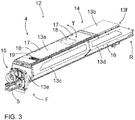
Figure 3 is a schematic view of a noise dampening structure arranged to cover a rock drilling unit partly; -
Figure 4 is a schematic and exploded view of a noise dampening device; -
Figure 5 is a schematic view of a protection panel which may substitute a noise dampening panel of a noise protector; and -
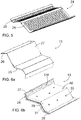
Figure 6a is a schematic view of a noise dampening panel seen from an outer surface side andFigure 6b shows the same panel from an inner surface side. - For the sake of clarity, the figures show some embodiments of the disclosed solution in a simplified manner. In the figures, like reference numerals identify like elements.
-
Figure 1 shows a rock drilling rig 1. The rock drilling rig 1 comprises amovable carrier 2 and at least oneboom 3 connected to thecarrier 2. At a distal end portion of theboom 3 is adrilling unit 4. Thedrilling unit 4 may comprise afeed beam 5 and arock drilling machine 6 supported on it. Therock drilling machine 6 may comprise a rotating unit for rotating atool 8. Further, therock drilling machine 6 comprises an impact device, which generates impact pulses for adrill bit 10 in order to form adrill hole 11. Since operation of therock drilling machine 6 causes noise, the rock drilling unit is surrounded at least partly by means of anoise dampening device 12. The noise dampener or protector may be as it is disclosed in this patent document. - Let it be mentioned that the disclosed noise dampening solution may also be used for other type of drilling rigs and drilling machines. Thereby, the disclosed solution may be implemented in rock drilling rigs intended for underground drilling and may be implemented also in rotary and DTH drilling as well as in exploration drilling.
-
Figure 2 discloses some features of a noise dampening device intended for rock drilling use. The features shown therein are already disclosed above in this patent document. -
Figure 3 discloses anoise dampening device 12, which comprises several removablenoise dampening panels 13a - 13f which form together askin structure 14 and an inner space inside which a rock drilling machine is mounted and which covers also afeed beam 5 at least partly. At a front end F of adrilling unit 4 may bedevices 15 or auxiliary components operation of which does not cause noise whereby they may be left outside thenoise protector 12. The dampeningpanels 13 may be fastened to a separate frame by means offastening elements 16, such as screws or quick coupling elements. Further, some of thepanels 13 may be coupled by means ofhinges 17 so that they may be turned T between open and close positions. Theskin structure 14 may comprise two or more longitudinally successivetop panels successive side panels noise protector 12, afront panel 13e, and further, one or morerear panels 13f at a rear end portion R of thenoise dampener 12. Further, one ormore panels 13 may be provided withtransparent monitoring sections 18. Alternatively, thepanels 13 may comprise openable small lids facilitating maintenance and monitoring, for example. Further, instead of fastening screws or corresponding elements,quick coupling locks 19 may be used for fastening thepanels 13. -
Figure 4 discloses that askin structure 14 may comprise several independentnoise dampening panels 13a - 13j, and aseparate frame 20 for supporting theskin structure 14 and for connecting it to a feed beam. Theframe 20 may be a rack type structure comprising twolongitudinal bars transverse supports 22 or support elements. The supports 22 may connect the frame to the feed beam or other components of the drilling unit and they may also serve as fastening surface for the panels. Alternatively, thesupports 22 are intended only for fastening the panels and theframe 20 is mounted by using separate fastening bars, elements or devices. As it is shown inFigure 4 , at the rear end R of theskin structure 14 may be two rear panels 13f1 and 13f2 which may both comprise anopening 23, which may be shaped to be rectangular. The rear panels may be arranged successively at a longitudinal distance from each other. -
Figure 5 discloses asubstitute panel 24 which may be mounted to a frame of a noise protector when no noise dampening is needed. Thepanel 24 may have a grating-like configuration whereby it comprises several throughopenings 25. Thepanel 24 may serve as mechanical protector preventing access to rotating and moving machine elements. Thepanel 24 may be dimensioned similarly as noise dampening panels and may comprisesimilar fastening openings 26 or fastening means as noise dampening panels, whereby the panels are compatible with the frame. -
Figures 6a and 6b disclose anoise dampening panel 13 comprising anouter layer 27, aninner layer 28 and amiddle layer 29. Theouter layer 27 may be made of aluminium alloy and it may be shaped into desired form by means of bending and other sheet machining techniques. On an inner surface of theouter layer 27 may be applied damping mass DM, which forms the mentionedmiddle layer 29. A light-weight absorbing element AE may be mounted to theouter layer 27 by means of mechanical fastening elements or pins 30. Further, edge areas of thepanel 13 may be provided withseals 31. - The drawings and the related description are only intended to illustrate the idea of the invention. In its details, the invention may vary within the scope of the claims.
Claims (12)
- A device (12) for dampening noise of a rock drilling unit (4), wherein the device (12) comprises:a skin structure (14), which is configured to form a space for receiving the rock drilling unit (4) at least partly; anda frame (20) for fastening the skin structure (14) to a feed beam (5) of the drilling unit (4);characterized in thatthe frame (20) and the skin structure (14) are separate elements; andthe skin structure (14) comprises several separate noise dampening panels (13) fastened to the frame (20) in a removable manner, whereby each panel (13) is individually mountable and dismountable.
- The device as claimed in claim 1, characterized in that
the frame (20) is one single unity extending longitudinally from a front end portion (F) to a rear end portion (R) of the device (12). - The device as claimed in claim 1 or 2, characterized in that
the frame (20) comprises a rack formed of metallic bars or tubes;
the rack comprises at least two parallel longitudinal bars (21a, 21b) connected to each other, and several transverse supports (22); and
the rack is provided with several fastening points for fastening the panels (13) mechanically to the rack. - The device as claimed in any one of the preceding claims 1 - 3, characterized in that
the skin structure (14) comprises at least three separate panels (13a - 13j). - The device as claimed in any one of the preceding claims 1 - 4, characterized in that
the skin structure (14) comprises at least two successive side panels (13a, 13b, 13g - 13j)on both longitudinal sides of the skin structure (14); at least one front panel (13e) at front end portion (F) and at least one rear panel (13f1, 13f2) at rear end portion (R) of the skin structure (14); and further at least two successive top panels (13a, 13b)on longitudinal top side of the skin structure (14). - The device as claimed in any one of the preceding claims 1 - 5, characterized in that
the skin structure (14) comprises at least one panel mounted by means of hinges (17) to the frame (20). - The device as claimed in any one of the preceding claims 1 - 6, characterized in that
at a rear portion (R) of the skin structure (14) is at least one rear panel (13f1, 13f2) provided with an opening (23) allowing the generated noise to spread through the opening (23) out of the space limited by the skin structure (14) . - The device as claimed in any one of the preceding claims 1 - 7, characterized in that
the panels (13) are fastened to the frame (20) by means of mechanical fastening elements (16). - The device as claimed in any one of the preceding claims 1 - 8, characterized in that
each of the panels (13) comprises an outer layer (27) and at least one additional layer (28, 29) connected on an inner side of the outer layer (27); and
the outer layer (27) is made of material impermeable to air and the at least one additional layer (28, 29) comprises noise dampening material. - The device as claimed in any one of the preceding claims 1 - 9, characterized in that
at least part of the noise dampening panels (13) comprises three superimposed layers, an outer layer (27), and inner layer (29) and a middle layer (28); and
the outer layer (27) is formed of metallic sheet material, the inner layer (29) comprises light-weight sound absorbing element (AE), and the middle layer (28) comprises damping mass (DA) applied directly on an inner surface side of the mentioned outer layer (27). - The device as claimed in any one of the preceding claims 1 - 10, characterized in that
the device (12) is provided with a pre-designed substitute system wherein at least some of the noise dampening plates (13) are changeable to plates (24) with corresponding dimensions and fastening means but having grating-like configuration with several through openings (25), whereby the device (12) is changeable from the noise damping device to a protective cage without any changes to the frame (20) . - A rock drilling rig (1) comprising:a movable carrier (2);at least one drilling boom (3);a drilling unit (4) at a distal end part of the drilling boom (3), wherein the drilling unit (4) comprises a feed beam (5) and a rock drilling machine (6) supported movably on the feed beam (5); anda noise damping device (12) comprising a skin structure (14) surrounding at least partly the drilling unit (4) and a frame (20) for supporting the device (14) to the drilling unit (4);characterized in thatthe noise damping device (14) is in accordance with the device disclosed in the previous claims 1 - 11.
Priority Applications (5)
| Application Number | Priority Date | Filing Date | Title |
|---|---|---|---|
| EP18189797.6A EP3613937B1 (en) | 2018-08-20 | 2018-08-20 | Device for noise damping and rock drilling rig |
| AU2019204374A AU2019204374A1 (en) | 2018-08-20 | 2019-06-21 | Device for noise damping and rock drilling rig |
| CN201910654031.1A CN110847812A (en) | 2018-08-20 | 2019-07-19 | Device for reducing noise and rock drilling rig |
| JP2019140494A JP7324080B2 (en) | 2018-08-20 | 2019-07-31 | Devices and drilling rigs for noise attenuation |
| US16/543,682 US10995551B2 (en) | 2018-08-20 | 2019-08-19 | Device for noise damping and rock drilling rig |
Applications Claiming Priority (1)
| Application Number | Priority Date | Filing Date | Title |
|---|---|---|---|
| EP18189797.6A EP3613937B1 (en) | 2018-08-20 | 2018-08-20 | Device for noise damping and rock drilling rig |
Publications (2)
| Publication Number | Publication Date |
|---|---|
| EP3613937A1 true EP3613937A1 (en) | 2020-02-26 |
| EP3613937B1 EP3613937B1 (en) | 2022-08-10 |
Family
ID=63311924
Family Applications (1)
| Application Number | Title | Priority Date | Filing Date |
|---|---|---|---|
| EP18189797.6A Active EP3613937B1 (en) | 2018-08-20 | 2018-08-20 | Device for noise damping and rock drilling rig |
Country Status (5)
| Country | Link |
|---|---|
| US (1) | US10995551B2 (en) |
| EP (1) | EP3613937B1 (en) |
| JP (1) | JP7324080B2 (en) |
| CN (1) | CN110847812A (en) |
| AU (1) | AU2019204374A1 (en) |
Families Citing this family (4)
| Publication number | Priority date | Publication date | Assignee | Title |
|---|---|---|---|---|
| US11759929B2 (en) * | 2014-07-28 | 2023-09-19 | Black & Decker Inc. | Power tool sound damping |
| AU2021243288B2 (en) | 2020-03-23 | 2023-07-20 | Ihi Corporation | Hydrocarbon generation system and hydrocarbon generation method |
| US12667949B2 (en) * | 2022-02-10 | 2026-06-30 | United States Of America As Represented By The Secretary Of The Air Force | Sound suppressing device attachment for tools |
| CN115035879A (en) * | 2022-05-27 | 2022-09-09 | 四川宏华石油设备有限公司 | Noise reduction device for top driving device of petroleum drilling machine |
Citations (5)
| Publication number | Priority date | Publication date | Assignee | Title |
|---|---|---|---|---|
| DE1905981U (en) * | 1964-09-28 | 1964-12-03 | Demag Ag | DEVICE FOR EMISSIONS IN THE CASE OF RAMMS AT MAEKLERS. |
| DE7312658U (en) * | 1973-04-04 | 1973-07-19 | Hochtief Ag | Sound insulation jacket for post drivers |
| DE3229998A1 (en) * | 1982-08-12 | 1984-02-16 | Ing. Günter Klemm, Spezialunternehmen für Bohrtechnik, 5962 Drolshagen | Drilling apparatus |
| WO2008007820A1 (en) * | 2006-07-12 | 2008-01-17 | Sung Bae Kim | Ram housing for pile driving hammer |
| WO2011029993A1 (en) * | 2009-09-08 | 2011-03-17 | Sandvik Mining And Construction Oy | Method for stiffening protective structure of rock drilling rig, and protective structure of rock drilling rig |
Family Cites Families (11)
| Publication number | Priority date | Publication date | Assignee | Title |
|---|---|---|---|---|
| JPS5445680Y2 (en) * | 1975-01-16 | 1979-12-27 | ||
| JPS5414848Y2 (en) * | 1975-04-25 | 1979-06-18 | ||
| FI69680C (en) | 1984-06-12 | 1986-03-10 | Tampella Oy Ab | FOERFARANDE FOER OPTIMERING AV BERGBORRNING |
| US4751979A (en) * | 1985-05-16 | 1988-06-21 | Airborne Express, Inc. | Engine noise suppression kit for the nacelles of a jet aircraft |
| JPH05295978A (en) * | 1992-04-20 | 1993-11-09 | San Giken Kk | Rock drilling equipment |
| JPH0685055A (en) * | 1992-09-04 | 1994-03-25 | Toshiba Corp | Manufacture of semiconductor element |
| JP2895334B2 (en) * | 1992-12-15 | 1999-05-24 | ライト工業株式会社 | Soundproofing |
| FI108561B (en) * | 1998-09-29 | 2002-02-15 | Tamrock Oy | Case for sound insulation of rock drilling equipment and arrangement with rock drilling equipment |
| FI123739B (en) * | 2007-04-04 | 2013-10-15 | Sandvik Mining & Constr Oy | Protective structure for a rock drilling rig for noise cancellation |
| FI20095923L (en) * | 2009-09-08 | 2011-03-09 | Sandvik Mining & Constr Oy | Rock drilling unit, feed beam and method for damping vibration |
| FI20096109L (en) * | 2009-10-28 | 2011-04-29 | Sandvik Mining & Constr Oy | Method for connecting a protective structure to a feeder beam and a protective structure for a mining actuator |
-
2018
- 2018-08-20 EP EP18189797.6A patent/EP3613937B1/en active Active
-
2019
- 2019-06-21 AU AU2019204374A patent/AU2019204374A1/en not_active Abandoned
- 2019-07-19 CN CN201910654031.1A patent/CN110847812A/en active Pending
- 2019-07-31 JP JP2019140494A patent/JP7324080B2/en active Active
- 2019-08-19 US US16/543,682 patent/US10995551B2/en active Active
Patent Citations (5)
| Publication number | Priority date | Publication date | Assignee | Title |
|---|---|---|---|---|
| DE1905981U (en) * | 1964-09-28 | 1964-12-03 | Demag Ag | DEVICE FOR EMISSIONS IN THE CASE OF RAMMS AT MAEKLERS. |
| DE7312658U (en) * | 1973-04-04 | 1973-07-19 | Hochtief Ag | Sound insulation jacket for post drivers |
| DE3229998A1 (en) * | 1982-08-12 | 1984-02-16 | Ing. Günter Klemm, Spezialunternehmen für Bohrtechnik, 5962 Drolshagen | Drilling apparatus |
| WO2008007820A1 (en) * | 2006-07-12 | 2008-01-17 | Sung Bae Kim | Ram housing for pile driving hammer |
| WO2011029993A1 (en) * | 2009-09-08 | 2011-03-17 | Sandvik Mining And Construction Oy | Method for stiffening protective structure of rock drilling rig, and protective structure of rock drilling rig |
Also Published As
| Publication number | Publication date |
|---|---|
| AU2019204374A1 (en) | 2020-03-05 |
| JP7324080B2 (en) | 2023-08-09 |
| EP3613937B1 (en) | 2022-08-10 |
| CN110847812A (en) | 2020-02-28 |
| JP2020051245A (en) | 2020-04-02 |
| US10995551B2 (en) | 2021-05-04 |
| US20200058281A1 (en) | 2020-02-20 |
Similar Documents
| Publication | Publication Date | Title |
|---|---|---|
| US10995551B2 (en) | Device for noise damping and rock drilling rig | |
| US8061449B2 (en) | Housing arrangement | |
| US8176682B2 (en) | Double panel door and double frame providing radio frequency shielding and soundproofing | |
| EP1657374B1 (en) | Thermal - Acoustic enclosure | |
| AU2010294119B2 (en) | Rock drilling unit, feed beam, and method for damping vibration | |
| US20060027149A1 (en) | Ablative blast resistant security door panel | |
| EP3408087B1 (en) | Multilayered panel for machinery enclosure | |
| ITPI20090013A1 (en) | ANTI-NOISE BARRIER WITH VARIABLE SOUND ABSORPTION AND SOUND ABSORPTION CHARACTERISTICS | |
| JP2895334B2 (en) | Soundproofing | |
| Camargo et al. | Engineered noise controls for miner safety and environmental responsibility | |
| JPH0470416A (en) | Soundproof device | |
| WO2008122694A1 (en) | Sound dampening housing for rock drill | |
| KR200481539Y1 (en) | Openable Baffle Wall Structure For Marine Facility | |
| CN119777515A (en) | A kind of splicable training site sound insulation and noise reduction wall panel and its use method | |
| KR101721887B1 (en) | Soundproof wall structure for tunnel | |
| CN109050203A (en) | Shelter air-conditioning anti-resonance mounting structure and its corresponding installation method | |
| Bender et al. | Noise Reduction of Jumbo Mounted Percussive Drills: Phase II–Development of Noise Treatment | |
| KR101487089B1 (en) | Apparatus for maintaining a lightweight panel thickness | |
| CN120621612A (en) | Ship cab integrated window installation method | |
| WO2017042755A1 (en) | Noise supression equipment |
Legal Events
| Date | Code | Title | Description |
|---|---|---|---|
| PUAI | Public reference made under article 153(3) epc to a published international application that has entered the european phase |
Free format text: ORIGINAL CODE: 0009012 |
|
| STAA | Information on the status of an ep patent application or granted ep patent |
Free format text: STATUS: REQUEST FOR EXAMINATION WAS MADE |
|
| 17P | Request for examination filed |
Effective date: 20190625 |
|
| AK | Designated contracting states |
Kind code of ref document: A1 Designated state(s): AL AT BE BG CH CY CZ DE DK EE ES FI FR GB GR HR HU IE IS IT LI LT LU LV MC MK MT NL NO PL PT RO RS SE SI SK SM TR |
|
| AX | Request for extension of the european patent |
Extension state: BA ME |
|
| GRAP | Despatch of communication of intention to grant a patent |
Free format text: ORIGINAL CODE: EPIDOSNIGR1 |
|
| STAA | Information on the status of an ep patent application or granted ep patent |
Free format text: STATUS: GRANT OF PATENT IS INTENDED |
|
| INTG | Intention to grant announced |
Effective date: 20220523 |
|
| GRAS | Grant fee paid |
Free format text: ORIGINAL CODE: EPIDOSNIGR3 |
|
| GRAA | (expected) grant |
Free format text: ORIGINAL CODE: 0009210 |
|
| STAA | Information on the status of an ep patent application or granted ep patent |
Free format text: STATUS: THE PATENT HAS BEEN GRANTED |
|
| AK | Designated contracting states |
Kind code of ref document: B1 Designated state(s): AL AT BE BG CH CY CZ DE DK EE ES FI FR GB GR HR HU IE IS IT LI LT LU LV MC MK MT NL NO PL PT RO RS SE SI SK SM TR |
|
| REG | Reference to a national code |
Ref country code: AT Ref legal event code: REF Ref document number: 1510672 Country of ref document: AT Kind code of ref document: T Effective date: 20220815 Ref country code: CH Ref legal event code: EP |
|
| REG | Reference to a national code |
Ref country code: IE Ref legal event code: FG4D |
|
| REG | Reference to a national code |
Ref country code: DE Ref legal event code: R096 Ref document number: 602018038997 Country of ref document: DE |
|
| REG | Reference to a national code |
Ref country code: FI Ref legal event code: FGE |
|
| REG | Reference to a national code |
Ref country code: SE Ref legal event code: TRGR |
|
| REG | Reference to a national code |
Ref country code: NL Ref legal event code: MP Effective date: 20220810 |
|
| REG | Reference to a national code |
Ref country code: LT Ref legal event code: MG9D |
|
| PG25 | Lapsed in a contracting state [announced via postgrant information from national office to epo] |
Ref country code: RS Free format text: LAPSE BECAUSE OF FAILURE TO SUBMIT A TRANSLATION OF THE DESCRIPTION OR TO PAY THE FEE WITHIN THE PRESCRIBED TIME-LIMIT Effective date: 20220810 Ref country code: PT Free format text: LAPSE BECAUSE OF FAILURE TO SUBMIT A TRANSLATION OF THE DESCRIPTION OR TO PAY THE FEE WITHIN THE PRESCRIBED TIME-LIMIT Effective date: 20221212 Ref country code: NO Free format text: LAPSE BECAUSE OF FAILURE TO SUBMIT A TRANSLATION OF THE DESCRIPTION OR TO PAY THE FEE WITHIN THE PRESCRIBED TIME-LIMIT Effective date: 20221110 Ref country code: NL Free format text: LAPSE BECAUSE OF FAILURE TO SUBMIT A TRANSLATION OF THE DESCRIPTION OR TO PAY THE FEE WITHIN THE PRESCRIBED TIME-LIMIT Effective date: 20220810 Ref country code: LV Free format text: LAPSE BECAUSE OF FAILURE TO SUBMIT A TRANSLATION OF THE DESCRIPTION OR TO PAY THE FEE WITHIN THE PRESCRIBED TIME-LIMIT Effective date: 20220810 Ref country code: LT Free format text: LAPSE BECAUSE OF FAILURE TO SUBMIT A TRANSLATION OF THE DESCRIPTION OR TO PAY THE FEE WITHIN THE PRESCRIBED TIME-LIMIT Effective date: 20220810 |
|
| REG | Reference to a national code |
Ref country code: AT Ref legal event code: MK05 Ref document number: 1510672 Country of ref document: AT Kind code of ref document: T Effective date: 20220810 |
|
| PG25 | Lapsed in a contracting state [announced via postgrant information from national office to epo] |
Ref country code: PL Free format text: LAPSE BECAUSE OF FAILURE TO SUBMIT A TRANSLATION OF THE DESCRIPTION OR TO PAY THE FEE WITHIN THE PRESCRIBED TIME-LIMIT Effective date: 20220810 Ref country code: IS Free format text: LAPSE BECAUSE OF FAILURE TO SUBMIT A TRANSLATION OF THE DESCRIPTION OR TO PAY THE FEE WITHIN THE PRESCRIBED TIME-LIMIT Effective date: 20221210 Ref country code: HR Free format text: LAPSE BECAUSE OF FAILURE TO SUBMIT A TRANSLATION OF THE DESCRIPTION OR TO PAY THE FEE WITHIN THE PRESCRIBED TIME-LIMIT Effective date: 20220810 Ref country code: GR Free format text: LAPSE BECAUSE OF FAILURE TO SUBMIT A TRANSLATION OF THE DESCRIPTION OR TO PAY THE FEE WITHIN THE PRESCRIBED TIME-LIMIT Effective date: 20221111 |
|
| REG | Reference to a national code |
Ref country code: CH Ref legal event code: PL |
|
| PG25 | Lapsed in a contracting state [announced via postgrant information from national office to epo] |
Ref country code: SM Free format text: LAPSE BECAUSE OF FAILURE TO SUBMIT A TRANSLATION OF THE DESCRIPTION OR TO PAY THE FEE WITHIN THE PRESCRIBED TIME-LIMIT Effective date: 20220810 Ref country code: RO Free format text: LAPSE BECAUSE OF FAILURE TO SUBMIT A TRANSLATION OF THE DESCRIPTION OR TO PAY THE FEE WITHIN THE PRESCRIBED TIME-LIMIT Effective date: 20220810 Ref country code: LU Free format text: LAPSE BECAUSE OF NON-PAYMENT OF DUE FEES Effective date: 20220820 Ref country code: LI Free format text: LAPSE BECAUSE OF NON-PAYMENT OF DUE FEES Effective date: 20220831 Ref country code: ES Free format text: LAPSE BECAUSE OF FAILURE TO SUBMIT A TRANSLATION OF THE DESCRIPTION OR TO PAY THE FEE WITHIN THE PRESCRIBED TIME-LIMIT Effective date: 20220810 Ref country code: DK Free format text: LAPSE BECAUSE OF FAILURE TO SUBMIT A TRANSLATION OF THE DESCRIPTION OR TO PAY THE FEE WITHIN THE PRESCRIBED TIME-LIMIT Effective date: 20220810 Ref country code: CZ Free format text: LAPSE BECAUSE OF FAILURE TO SUBMIT A TRANSLATION OF THE DESCRIPTION OR TO PAY THE FEE WITHIN THE PRESCRIBED TIME-LIMIT Effective date: 20220810 Ref country code: CH Free format text: LAPSE BECAUSE OF NON-PAYMENT OF DUE FEES Effective date: 20220831 Ref country code: AT Free format text: LAPSE BECAUSE OF FAILURE TO SUBMIT A TRANSLATION OF THE DESCRIPTION OR TO PAY THE FEE WITHIN THE PRESCRIBED TIME-LIMIT Effective date: 20220810 |
|
| REG | Reference to a national code |
Ref country code: BE Ref legal event code: MM Effective date: 20220831 |
|
| REG | Reference to a national code |
Ref country code: DE Ref legal event code: R097 Ref document number: 602018038997 Country of ref document: DE |
|
| PG25 | Lapsed in a contracting state [announced via postgrant information from national office to epo] |
Ref country code: SK Free format text: LAPSE BECAUSE OF FAILURE TO SUBMIT A TRANSLATION OF THE DESCRIPTION OR TO PAY THE FEE WITHIN THE PRESCRIBED TIME-LIMIT Effective date: 20220810 Ref country code: MC Free format text: LAPSE BECAUSE OF FAILURE TO SUBMIT A TRANSLATION OF THE DESCRIPTION OR TO PAY THE FEE WITHIN THE PRESCRIBED TIME-LIMIT Effective date: 20220810 Ref country code: EE Free format text: LAPSE BECAUSE OF FAILURE TO SUBMIT A TRANSLATION OF THE DESCRIPTION OR TO PAY THE FEE WITHIN THE PRESCRIBED TIME-LIMIT Effective date: 20220810 |
|
| PLBE | No opposition filed within time limit |
Free format text: ORIGINAL CODE: 0009261 |
|
| STAA | Information on the status of an ep patent application or granted ep patent |
Free format text: STATUS: NO OPPOSITION FILED WITHIN TIME LIMIT |
|
| PG25 | Lapsed in a contracting state [announced via postgrant information from national office to epo] |
Ref country code: AL Free format text: LAPSE BECAUSE OF FAILURE TO SUBMIT A TRANSLATION OF THE DESCRIPTION OR TO PAY THE FEE WITHIN THE PRESCRIBED TIME-LIMIT Effective date: 20220810 |
|
| P01 | Opt-out of the competence of the unified patent court (upc) registered |
Effective date: 20230603 |
|
| 26N | No opposition filed |
Effective date: 20230511 |
|
| GBPC | Gb: european patent ceased through non-payment of renewal fee |
Effective date: 20221110 |
|
| PG25 | Lapsed in a contracting state [announced via postgrant information from national office to epo] |
Ref country code: IE Free format text: LAPSE BECAUSE OF NON-PAYMENT OF DUE FEES Effective date: 20220820 |
|
| PG25 | Lapsed in a contracting state [announced via postgrant information from national office to epo] |
Ref country code: SI Free format text: LAPSE BECAUSE OF FAILURE TO SUBMIT A TRANSLATION OF THE DESCRIPTION OR TO PAY THE FEE WITHIN THE PRESCRIBED TIME-LIMIT Effective date: 20220810 |
|
| PG25 | Lapsed in a contracting state [announced via postgrant information from national office to epo] |
Ref country code: BE Free format text: LAPSE BECAUSE OF NON-PAYMENT OF DUE FEES Effective date: 20220831 |
|
| PG25 | Lapsed in a contracting state [announced via postgrant information from national office to epo] |
Ref country code: GB Free format text: LAPSE BECAUSE OF NON-PAYMENT OF DUE FEES Effective date: 20221110 |
|
| PG25 | Lapsed in a contracting state [announced via postgrant information from national office to epo] |
Ref country code: HU Free format text: LAPSE BECAUSE OF FAILURE TO SUBMIT A TRANSLATION OF THE DESCRIPTION OR TO PAY THE FEE WITHIN THE PRESCRIBED TIME-LIMIT; INVALID AB INITIO Effective date: 20180820 |
|
| PG25 | Lapsed in a contracting state [announced via postgrant information from national office to epo] |
Ref country code: CY Free format text: LAPSE BECAUSE OF FAILURE TO SUBMIT A TRANSLATION OF THE DESCRIPTION OR TO PAY THE FEE WITHIN THE PRESCRIBED TIME-LIMIT Effective date: 20220810 |
|
| PG25 | Lapsed in a contracting state [announced via postgrant information from national office to epo] |
Ref country code: MK Free format text: LAPSE BECAUSE OF FAILURE TO SUBMIT A TRANSLATION OF THE DESCRIPTION OR TO PAY THE FEE WITHIN THE PRESCRIBED TIME-LIMIT Effective date: 20220810 Ref country code: IT Free format text: LAPSE BECAUSE OF FAILURE TO SUBMIT A TRANSLATION OF THE DESCRIPTION OR TO PAY THE FEE WITHIN THE PRESCRIBED TIME-LIMIT Effective date: 20220810 |
|
| PG25 | Lapsed in a contracting state [announced via postgrant information from national office to epo] |
Ref country code: TR Free format text: LAPSE BECAUSE OF FAILURE TO SUBMIT A TRANSLATION OF THE DESCRIPTION OR TO PAY THE FEE WITHIN THE PRESCRIBED TIME-LIMIT Effective date: 20220810 |
|
| PG25 | Lapsed in a contracting state [announced via postgrant information from national office to epo] |
Ref country code: BG Free format text: LAPSE BECAUSE OF FAILURE TO SUBMIT A TRANSLATION OF THE DESCRIPTION OR TO PAY THE FEE WITHIN THE PRESCRIBED TIME-LIMIT Effective date: 20220810 |
|
| PG25 | Lapsed in a contracting state [announced via postgrant information from national office to epo] |
Ref country code: MT Free format text: LAPSE BECAUSE OF FAILURE TO SUBMIT A TRANSLATION OF THE DESCRIPTION OR TO PAY THE FEE WITHIN THE PRESCRIBED TIME-LIMIT Effective date: 20220810 |
|
| PGFP | Annual fee paid to national office [announced via postgrant information from national office to epo] |
Ref country code: FI Payment date: 20250814 Year of fee payment: 8 |
|
| PGFP | Annual fee paid to national office [announced via postgrant information from national office to epo] |
Ref country code: DE Payment date: 20250702 Year of fee payment: 8 |
|
| PGFP | Annual fee paid to national office [announced via postgrant information from national office to epo] |
Ref country code: FR Payment date: 20250721 Year of fee payment: 8 |
|
| PGFP | Annual fee paid to national office [announced via postgrant information from national office to epo] |
Ref country code: SE Payment date: 20250702 Year of fee payment: 8 |