EP3613902A1 - Fender device - Google Patents
Fender device Download PDFInfo
- Publication number
- EP3613902A1 EP3613902A1 EP17905287.3A EP17905287A EP3613902A1 EP 3613902 A1 EP3613902 A1 EP 3613902A1 EP 17905287 A EP17905287 A EP 17905287A EP 3613902 A1 EP3613902 A1 EP 3613902A1
- Authority
- EP
- European Patent Office
- Prior art keywords
- shock
- convex part
- absorbing member
- fender device
- peripheral line
- Prior art date
- Legal status (The legal status is an assumption and is not a legal conclusion. Google has not performed a legal analysis and makes no representation as to the accuracy of the status listed.)
- Granted
Links
Images




Classifications
-
- E—FIXED CONSTRUCTIONS
- E02—HYDRAULIC ENGINEERING; FOUNDATIONS; SOIL SHIFTING
- E02B—HYDRAULIC ENGINEERING
- E02B3/00—Engineering works in connection with control or use of streams, rivers, coasts, or other marine sites; Sealings or joints for engineering works in general
- E02B3/20—Equipment for shipping on coasts, in harbours or on other fixed marine structures, e.g. bollards
- E02B3/26—Fenders
-
- Y—GENERAL TAGGING OF NEW TECHNOLOGICAL DEVELOPMENTS; GENERAL TAGGING OF CROSS-SECTIONAL TECHNOLOGIES SPANNING OVER SEVERAL SECTIONS OF THE IPC; TECHNICAL SUBJECTS COVERED BY FORMER USPC CROSS-REFERENCE ART COLLECTIONS [XRACs] AND DIGESTS
- Y02—TECHNOLOGIES OR APPLICATIONS FOR MITIGATION OR ADAPTATION AGAINST CLIMATE CHANGE
- Y02A—TECHNOLOGIES FOR ADAPTATION TO CLIMATE CHANGE
- Y02A30/00—Adapting or protecting infrastructure or their operation
- Y02A30/30—Adapting or protecting infrastructure or their operation in transportation, e.g. on roads, waterways or railways
Definitions
- the present invention relates to a fender device for protecting a ship during berthing.
- a fender device may be installed on a boarding surface of a quay or a pier or the like in order to alleviate shock during berthing of a ship at the boarding surface.
- fender devices there are various types of fender devices existing, one type including a tubular shock-absorbing member installed so that a center axis is along a normal direction of the boarding surface (see Patent Documents 1 and 2).
- the shock-absorbing member is made of an elastic material such as rubber or the like, and absorbs energy of the shock by being compressively deformed in the direction of the center axis when pushed by the ship. Accordingly, damage to the ship and the boarding surface can be avoided.
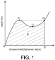
- FIG. 1 shows a characteristic curve indicating a relationship between compression ratio and reaction force when a shock-absorbing member of the above type is compressed.
- this type of shock-absorbing member As shown in the same figure, in this type of shock-absorbing member, as the shock-absorbing member is pushed by the ship and the compression progresses, the reaction force gradually increases from an origin O corresponding to a state in which the shock-absorbing member is not being compressed, and the shock-absorbing member buckles when a certain point (maximum point P 1 ) is reached. After that, although the reaction force gradually decreases due to the buckling, when a certain point (minimum point P 2 ) is reached, the shock-absorbing member starts to behave as a rubber mass. For that reason, the reaction force turns to increase again at point P 2 , passes through point P 3 at which the reaction force is the same as at point P 1 , and the reaction force continues to increase even after that.
- a range of the compression ratio at which the purpose of fenders can be achieved is set to a range until reaching a compression ratio (hereinafter "critical compression ratio") C corresponding to point P 3 .
- critical compression ratio a compression ratio
- the amount of the energy that can be absorbed by the shock-absorbing member in the compression ratio range of 0 to C is equivalent to an area B of a region surrounded by the characteristic curve, the horizontal axis passing through the origin O and the vertical axis passing through point P 3 . Therefore, it is important to increase the area B in the fender device.
- Patent Document 1 discloses a fender device in which a convex part is provided along a peripheral direction on an inner surface of a hollow truncated cone-shaped shock-absorbing member.
- a timing at which the inner surfaces on both sides of the convex part contact each other is delayed. Accordingly, the amount of the energy that can be absorbed by the shock-absorbing member until reaching the critical compression ratio, i.e., the area B, is increased.
- fender devices if of the same size, are desired to have a larger energy absorption amount, and, if having the same energy absorption amount, are desired to be smaller in size, and there is an increasing demand for fender devices with higher shock-absorbing performance.
- the present invention aims to improve the shock-absorbing performance of a fender device.
- a fender device is a fender device attached to a boarding surface at which a ship berths, the fender device including a tubular shock-absorbing member.
- the shock-absorbing member is made of an elastic material, has a center axis extending in a normal direction of the boarding surface, is compressed in the direction of the center axis, and buckles in a compression process.
- the shock-absorbing member has an inner surface, and includes a first convex part that is formed on the inner surface along a peripheral direction during non-compression and a second convex part that is formed in the vicinity of the first convex part on the inner surface along the peripheral direction during non-compression.
- the inner surface includes a first peripheral line and a second peripheral line.
- the first peripheral line defines a boundary of the first convex part that is a boundary opposite the second convex part.
- the second peripheral line defines a boundary of the first convex part that is a boundary on the second convex part side.
- the shock-absorbing member bends along the first peripheral line and the second peripheral line during buckling.
- a fender device is the fender device according to the first aspect, wherein the first convex part is disposed inside a part of the shock-absorbing member that bends so as to protrude outward during buckling of the shock-absorbing member.
- a fender device is the fender device according to the first aspect or the second aspect, wherein a boundary of the second convex part on the first convex part side is defined by the second peripheral line.
- a fender device is the fender device according to any one of the first to third aspects, wherein during buckling of the shock-absorbing member, a portion on the first convex part side included in the second convex part makes surface contact along the peripheral direction with a portion on the second convex part side included in the first convex part.
- a fender device is the fender device according to any one of the first to fourth aspects, wherein the shock-absorbing member is roughly in a shape of a hollow truncated cone and has a first end face along the normal direction of the boarding surface and a second end face larger in diameter than the first end face.
- a fender device is the fender device according to the fifth aspect, wherein the second convex part is disposed on a second end face side of the first convex part.
- a fender device is the fender device according to the fifth aspect or the sixth aspect, wherein during 50% compression of the shock-absorbing member, the first peripheral line is located closer to the first end face side than the second peripheral line.
- a fender device is the fender device according to any one of the fifth to seventh aspects, wherein during 70% compression of the shock-absorbing member, the first peripheral line is located closer to the first end face side than the second peripheral line.
- a fender device is the fender device according to any one of the fifth to eighth aspects, wherein during compression of the shock-absorbing member at a critical compression ratio, the first peripheral line is located closer to the first end face side than the second peripheral line.
- a fender device is the fender device according to any one of the first to ninth aspects, wherein the first convex part is continuously formed over an entire circumference.
- a fender device is the fender device according to any one of the first to tenth aspects, wherein the second convex part is continuously formed over the entire circumference.
- a fender device is the fender device according to any one of the first to eleventh aspects, further including a shock-receiving member disposed on the ship side of the shock-absorbing member and contacting the ship.
- the tubular shock-absorbing member included in the fender device according to the present invention is made of the elastic material, has the center axis extending in the normal direction of the boarding surface, is compressed in the direction of the center axis, and buckles in the compression process.
- the first and second convex parts extending along the peripheral direction are formed on the inner surface of the shock-absorbing member during non-compression, wherein the second convex part is disposed in the vicinity of the first convex part.
- the shock-absorbing member is configured to bend along the first and second peripheral lines on both sides of the first convex part during buckling. As a result, it becomes difficult to compress the shock-absorbing member due to the presence of the first convex part, and the shock-absorbing member thus increases in the critical compression ratio.
- the shock-absorbing performance of the fender device is improved.
- a fender device according to an embodiment of the present invention is hereinafter explained with reference to the drawings.
- FIG. 2 shows a cross-sectional view of a fender device 1 according to the present embodiment.
- the fender device 1 is attached to a boarding surface 5 of a quay or a pier or the like at which a ship berths, and alleviates shock during berthing of the ship at the boarding surface 5.
- the fender device 1 includes a shock-receiving member 10 in direct contact with a side surface of the ship or the like, and further includes an elastically deformable shock-absorbing member 20 between the shock-receiving member 10 and the boarding surface 5.
- FIG. 2 shows a normal state in which no external force is applied to the shock-receiving member 10, i.e., the fender device 1 during non-compression of the shock-absorbing member 20.
- the shock-receiving member 10 is disposed on a ship side of the shock-absorbing member 20 along a normal direction (hereinafter "direction A1") of the boarding surface 5.
- the shock-receiving member 10 has a shock-receiving plate 11 made of steel.
- a surface member 12 made of a material having lower rigidity is fixed to an outer surface 11a on the ship side of the shock-receiving plate 11 in order to prevent damage to the ship.
- the surface member 12 is made of rubber or resin.
- the shock-receiving plate 11 is installed parallel or substantially parallel to the boarding surface 5.
- the shock-receiving member 10 As a whole has a platelike shape .
- the shape does not matter as long as the shock-receiving member 10 is capable of appropriately receiving the side surface of the ship or the like.
- the material of the shock-receiving plate 11 is not limited to steel but may be other metal, or may be resin or ceramic, as long as the rigidity suitable for the function as the shock-receiving plate can be secured.
- the surface member 12 can also be omitted.
- the shock-absorbing member 20 is disposed on the boarding surface 5 side of the shock-receiving plate 11 along the direction A1. More specifically, the shock-absorbing member 20 is attached to a back surface 11b side of the shock-receiving plate 11 with a spacer 30 sandwiched therebetween.
- the spacer 30 is disposed between the shock-receiving plate 11 and the shock-absorbing member 20 along the direction A1 during non-compression of the shock-absorbing member 20.
- the spacer 30 is a cylindrical member whose center axis extends parallel or substantially parallel to the direction A1.
- the shape of the spacer 30 is not limited to this example and may be, for example, a ring shape or a prism shape.
- the spacer 30 is directly connected to the back surface 11b of the shock-receiving plate 11.
- a mode of the connection can be appropriately selected.
- the connection can be achieved by welding and/or by using a fastener such as a bolt or the like.
- the spacer 30 can be omitted, and the shock-receiving plate 11 and the shock-absorbing member 20 can be directly connected.
- the spacer 30 has a function of increasing a critical compression ratio C of the shock-absorbing member 20 and thus increasing the amount of energy that can be absorbed by the shock-absorbing member 20; in that respect, it is preferable to provide the spacer 30.
- the material of the spacer 30 is not particularly limited. Although the spacer 30 is made of steel in the present embodiment, it may be made of other metal, or may be made of resin or ceramic, as long as the above function can be secured.
- the shock-absorbing member 20 is directly connected to the boarding surface 5 side of the spacer 30.
- a mode of the connection can be appropriately selected.
- the connection can be achieved by using a fastener such as a bolt or the like.
- the connection can be achieved by inserting a bolt into a screwless bolt hole of the spacer 30 and fixing the bolt by a cap nut embedded in the shock-absorbing member 20.
- FIG. 3 is a perspective view of the shock-absorbing member 20.
- the shock-absorbing member 20 has a roughly truncated conical outer shape having a center axis extending parallel or substantially parallel to the direction A1, and is composed of a hollow structure forming an internal space S1.
- the internal space S1 is roughly closed by the boarding surface 5 and the spacer 30 when the shock-absorbing member 20 is attached to the boarding surface 5.
- the shock-absorbing member 20 has a first end face 21a and a second end face 22a along the direction A1, and the second end face 22a is larger in diameter than the first end face 21a.
- the shock-absorbing member 20 is a tubular member gradually increasing in diameter along the direction A1 from the first end face 21a side to the second end face 22a side.
- an end part 21 on the first end face 21a side is cylindrical without increasing in diameter along the direction A1, and is directly connected to the spacer 30 at the first end face 21a.
- an end part 22 on the second end face 22a side has a flange shape with respect to a body part 26 of the shock-absorbing member 20. Therefore, in the following, the end part 22 may be referred to as flange part 22.
- the flange part 22 is in the shape of a thin ring having a roughly constant diameter along the direction A1.
- the end part 21, the body part 26 and the flange part 22 are disposed coaxially with the direction A1 as the center axis, and are continuous in this order from the shock-receiving plate 11 side to the boarding surface 5 side along the direction A1.
- the first end face 21a is disposed on the shock-receiving plate 11 side
- the second end face 22a is disposed on the boarding surface 5 side.
- the body part 26 rather than the shock-absorbing member 20 is configured in a tubular shape having a roughly truncated conical outer shape, gradually increasing in diameter along the direction A1.
- the body part 26 has a roughly constant thickness except for a first convex part 71 and a second convex part 72 to be described later.
- the end parts 21 and 22 are wider in a radial direction (larger in thickness) than the body part 26. This is because the end parts 21 and 22 are attachment parts and require sufficient rigidity, and this makes it easier for the end parts 21 and 22 to be embedded in later-described steel plates 41 and 42 and be attached to the boarding surface 5.
- "radial direction” and “peripheral direction” are based on the center axis of the shock-absorbing member 20.
- the flange part 22 is directly connected to the boarding surface 5 at the second end face 22a.
- the boarding surface 5 is generally composed of concrete.
- through holes 24 extending parallel or substantially parallel to the direction A1 are formed at a plurality of positions along the peripheral direction, and fasteners such as bolts or the like are inserted into the boarding surface 5 via the through holes 24. Accordingly, the fender device 1 is firmly fixed to the boarding surface 5.
- the through holes 24 serve to fix the fender device 1 and the boarding surface 5, they are preferably disposed at constant intervals in the peripheral direction so that an external force applied to the fender device 1 is equally distributed.
- a plurality of convex parts 23 protruding outward in the radial direction are formed along the peripheral direction.
- the convex parts 23 and the through holes 24 are alternately disposed along the peripheral direction.
- the shock-absorbing member 20 is made of an elastic material, receives the energy of collision with the ship and can be compressively deformed in the direction A1. That is, when an external force is applied in a direction from the ship to the boarding surface 5 side, by bending so as to protrude outward in the radial direction, the shock-absorbing member 20 is compressively deformed in the direction A1 (see FIG. 4 ). At this moment, the shock-absorbing member 20 buckles in the compression process. In addition, the shock-absorbing member 20 is restored to its original shape when the external force is removed.
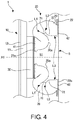
- FIG. 4 shows the fender device 1 in a state in which an external force in the direction A1 is applied to the shock-receiving plate 11 in the normal state of FIG. 2 , and whereby the shock-absorbing member 20 is compressively deformed in the direction A1.
- the above-mentioned convex parts 23 are useful for compressively deforming the shock-absorbing member 20 into a constant shape, and are capable of stabilizing amount of energy absorption by compressive deformation.
- the convex parts 23 are also preferably disposed at constant intervals in the peripheral direction.
- the ring-shaped steel plates (iron plates) 41 and 42 are embedded respectively.
- the steel plates 41 and 42 have a constant thickness in the direction A1, and respectively serve to improve strength of the end parts 21 and 22 of the shock-absorbing member 20.
- the steel plates 41 and 42 also serve to improve connection strength between the end parts 21, 22 and the spacer 30 and the boarding surface 5, respectively, and the fasteners such as bolts or the like for the above-mentioned connection are attached so as to penetrate the steel plates 41 and 42.
- the shock-absorbing member 20 is compressively deformed in the direction A1 by bending so as to protrude outward in the radial direction.
- the body part 26 in the shock-absorbing member 20 that is compressively deformed in such a mode. Even if an external force is applied in the direction from the ship to the boarding surface 5 side, unlike the body part 26, the end parts 21 and 22 do not bend so as to protrude outward in the radial direction and are hardly compressively deformed in the direction A1.
- the shock-absorbing member 20 by configuring the inner surface 20a thereof as follows, the energy absorption amount until the shock-absorbing member 20 reaches the critical compression ratio C (the compression ratio corresponding to point P 3 in FIG. 1 ), i.e., the area B, increases.
- the compression ratio is given by (Q1-Q2) ⁇ 100/Q1(%), where a length of the shock-absorbing member 20 in the direction A1 when no external force is applied and the shock-absorbing member 20 is not compressed at all is set to Q1, and the length of the shock-absorbing member 20 during compression of the shock-absorbing member 20 is set to Q2. That is, when a displacement amount of the first end face 21a of the shock-absorbing member 20 in the direction A1 is set to d1, the compression ratio is given by d1 ⁇ 100/Q1(%).
- the first convex part 71 and the second convex part 72 are formed on the inner surface 20a of the body part 26 of the shock-absorbing member 20 during non-compression of the shock-absorbing member 20.
- the second convex part 72 is disposed in the vicinity of the first convex part 71, and in the present embodiment, is disposed on the second end face 22a side (i.e., on the boarding surface 5 side) of the first convex part 71 along the direction A1.
- the first convex part 71 and the second convex part 72 are each formed along the peripheral direction, and in the present embodiment, are each continuously formed without interruption over the entire circumference.
- a boundary of the first convex part 71 that is a boundary opposite the second convex part 72 is defined by a first peripheral line L1 extending along the peripheral direction.
- a boundary of the first convex part 71 that is a boundary on the second convex part 72 side is defined by a second peripheral line L2 extending along the peripheral direction.
- the first convex part 71 and the second convex part 72 are adjacent to each other.
- a boundary of the second convex part 72 that is a boundary on the first convex part 71 side is defined by the second peripheral line L2.
- a boundary of the second convex part 72 that is a boundary opposite the first convex part 71 is defined by a third peripheral line L3.
- This straight line is indicated by M1 in FIG. 2 .
- the second convex part 72 is a portion protruding inward in the radial direction from a surface (indicated by a dotted line in FIG. 2 ) linearly connecting the peripheral lines L2 and L3 on the cross section of the shock-absorbing member 20.
- the line representing the inner surface 20a on the cross section of the shock-absorbing member 20 is not smoothly continuous at a position of a point representing the peripheral line L1 during non-compression of the shock-absorbing member 20 (not differentiable at the position of the point representing the peripheral line L1).
- the same line is not smoothly continuous even at a position of a point representing the peripheral line L2 (not differentiable at the position of the point representing the peripheral line L2).
- the line representing the inner surface 20a on the cross section of the shock-absorbing member 20 is smoothly continuous before and after a point representing the peripheral line L3 during non-compression of the shock-absorbing member 20 (differentiable at a position of the point representing the peripheral line L3).
- shock-absorbing member 20 during compression is explained.
- the explanation is given in the following based on a result of a simulation actually performed by the present inventors with respect to the above-mentioned shock-absorbing member 20 (Example).
- the simulation was performed not only with respect to the shock-absorbing member 20 according to the Example but also with respect to a shock-absorbing member according to a Comparative Example.
- On the left side of FIG. 5 cross-sectional views of the shock-absorbing member 20 according to the Example at various compression ratios are shown; on the right side of FIG. 5 , cross-sectional views of the shock-absorbing member according to the Comparative Example at various compression ratios are shown.
- the shock-absorbing member according to the Comparative Example is obtained by omitting the second convex part 72 from the shock-absorbing member 20 according to the Example, and has the same configuration as the shock-absorbing member 20 in other respects.
- FIG. 6 shows characteristic curves indicating a relationship between compression ratio and reaction force of the shock-absorbing members according to the Example and the Comparative Example. As shown in the same figure, in the shock-absorbing member 20 according to the Example, the reaction force reached the maximum value (corresponding to point P 1 ) at the compression ratio of about 35%, and buckling was started.
- the shock-absorbing member 20 bent along the first peripheral line L1 and the second peripheral line L2, and the first convex part 71 was compressed between the second convex part 72 and a portion 73 opposite the second convex part 72. From this moment onward, as the compression progressed, the first convex part 71 gradually changed to a mountain shape describing a sharper curve. As a result, during buckling, a portion on the first convex part 71 side included in the second convex part 72 made surface contact along the peripheral direction with a portion on the second convex part 72 side included in the first convex part 71.
- a portion on the first convex part 71 side included in the portion 73 also made surface contact along the peripheral direction with a portion on the portion 73 side included in the first convex part 71.
- a central part 25 of the shock-absorbing member 20 in the direction A1 bent so as to protrude outward over the entire peripheral direction.
- the first convex part 71 was disposed at a position facing a part of the central part 25 that protruded most outward. That is, the first convex part 71 was disposed inside a part of the shock-absorbing member 20 that bends so as to protrude outward during buckling of the shock-absorbing member 20.
- the shock-absorbing member according to the Comparative Example As shown in FIG. 6 , in the shock-absorbing member according to the Comparative Example, similarly, the reaction force reached the maximum value (corresponding to point P 1 ) at the compression ratio of about 35%, and buckling was started. From this moment onward, as the compression progressed, the first convex part 71 began to fall toward the internal space S1 side. As shown in FIG. 5 , when the compression ratio exceeded 50%, the first peripheral line L1 reached a position closer to the second end face 22a side (boarding surface side) along the direction A1 than the second peripheral line L2.
- the first convex part 71 was supported by the second convex part 72 after the start of the buckling, with the result that the first peripheral line L1 was maintained at a position closer to the first end face 21a side (ship side) along the direction A1 than the second peripheral line L2 even at the compression ratio of 50%.
- the first peripheral line L1 was still maintained at the position closer to the first end face 21a side (ship side) along the direction A1 than the second peripheral line L2, was located on the first end face 21a side (ship side) even at the compression ratio of 70%, and was located on the first end face 21a side (ship side) even during maximum compression (during compression at the critical compression ratio).
- the critical compression ratio was 70%
- the critical compression ratio of the shock-absorbing member 20 according to the Example was 77%. That is, due to the presence of the second convex part 72, the critical compression ratio increased by 7%.
- the critical compression ratio was reached, the mountain shape of the first convex part 71 remained and a small gap S2 was formed on the mountain.
- the shock-absorbing member according to the Comparative Example the mountain of the first convex part 71 collapsed, and the first convex part 71 became substantially planar.
- shock-absorbing member 20 is roughly in the shape of a hollow truncated cone in the above embodiments, it is not limited to this shape and may be cylindrical, for example.
- shock-absorbing member 20 is attached to the boarding surface 5 at the second end face 22a side larger in diameter in the above embodiments, it may also be attached to the boarding surface 5 at the first end face 21a side smaller in diameter.
- the first convex part 71 and the second convex part 72 may not be adjacent to each other. That is, the boundary of the first convex part 71 being the boundary on the second convex part 72 side and the boundary of the second convex part 72 being the boundary on the first convex part 71 side may be defined by different peripheral lines.
- the second convex part 72 supporting the first convex part 71 protruding during buckling may be disposed closer to the ship side or to the first end face 21a side smaller in diameter than the first convex part 71 along the direction A1.
Landscapes
- Engineering & Computer Science (AREA)
- General Engineering & Computer Science (AREA)
- Ocean & Marine Engineering (AREA)
- Environmental & Geological Engineering (AREA)
- Mechanical Engineering (AREA)
- Civil Engineering (AREA)
- Structural Engineering (AREA)
- Vibration Dampers (AREA)
Abstract
Description
- The present invention relates to a fender device for protecting a ship during berthing.
- A fender device may be installed on a boarding surface of a quay or a pier or the like in order to alleviate shock during berthing of a ship at the boarding surface. There are various types of fender devices existing, one type including a tubular shock-absorbing member installed so that a center axis is along a normal direction of the boarding surface (see
Patent Documents 1 and 2). Typically, the shock-absorbing member is made of an elastic material such as rubber or the like, and absorbs energy of the shock by being compressively deformed in the direction of the center axis when pushed by the ship. Accordingly, damage to the ship and the boarding surface can be avoided. -
FIG. 1 shows a characteristic curve indicating a relationship between compression ratio and reaction force when a shock-absorbing member of the above type is compressed. As shown in the same figure, in this type of shock-absorbing member, as the shock-absorbing member is pushed by the ship and the compression progresses, the reaction force gradually increases from an origin O corresponding to a state in which the shock-absorbing member is not being compressed, and the shock-absorbing member buckles when a certain point (maximum point P1) is reached. After that, although the reaction force gradually decreases due to the buckling, when a certain point (minimum point P2) is reached, the shock-absorbing member starts to behave as a rubber mass. For that reason, the reaction force turns to increase again at point P2, passes through point P3 at which the reaction force is the same as at point P1, and the reaction force continues to increase even after that. - Generally, in the shock-absorbing member as above, a range of the compression ratio at which the purpose of fenders can be achieved is set to a range until reaching a compression ratio (hereinafter "critical compression ratio") C corresponding to point P3. This is because the reaction force may become too high at point P3 onward, and problems such as damage to the ship body and so on may be caused. The amount of the energy that can be absorbed by the shock-absorbing member in the compression ratio range of 0 to C is equivalent to an area B of a region surrounded by the characteristic curve, the horizontal axis passing through the origin O and the vertical axis passing through point P3. Therefore, it is important to increase the area B in the fender device.
- In this regard,
Patent Document 1 discloses a fender device in which a convex part is provided along a peripheral direction on an inner surface of a hollow truncated cone-shaped shock-absorbing member. InPatent Document 1, due to the presence of this convex part, a timing at which the inner surfaces on both sides of the convex part contact each other is delayed. Accordingly, the amount of the energy that can be absorbed by the shock-absorbing member until reaching the critical compression ratio, i.e., the area B, is increased. -
- Patent Document 1: Japanese Laid-open No.
2001-172940 - Patent Document 1: Japanese Laid-open No.
2016-148240 - However, in recent years, while attention is being paid to environmental problems, fender devices, if of the same size, are desired to have a larger energy absorption amount, and, if having the same energy absorption amount, are desired to be smaller in size, and there is an increasing demand for fender devices with higher shock-absorbing performance.
- The present invention aims to improve the shock-absorbing performance of a fender device.
- A fender device according to a first aspect of the present invention is a fender device attached to a boarding surface at which a ship berths, the fender device including a tubular shock-absorbing member. The shock-absorbing member is made of an elastic material, has a center axis extending in a normal direction of the boarding surface, is compressed in the direction of the center axis, and buckles in a compression process. The shock-absorbing member has an inner surface, and includes a first convex part that is formed on the inner surface along a peripheral direction during non-compression and a second convex part that is formed in the vicinity of the first convex part on the inner surface along the peripheral direction during non-compression. The inner surface includes a first peripheral line and a second peripheral line. The first peripheral line defines a boundary of the first convex part that is a boundary opposite the second convex part. The second peripheral line defines a boundary of the first convex part that is a boundary on the second convex part side. The shock-absorbing member bends along the first peripheral line and the second peripheral line during buckling.
- A fender device according to a second aspect of the present invention is the fender device according to the first aspect, wherein the first convex part is disposed inside a part of the shock-absorbing member that bends so as to protrude outward during buckling of the shock-absorbing member.
- A fender device according to a third aspect of the present invention is the fender device according to the first aspect or the second aspect, wherein a boundary of the second convex part on the first convex part side is defined by the second peripheral line.
- A fender device according to a fourth aspect of the present invention is the fender device according to any one of the first to third aspects, wherein during buckling of the shock-absorbing member, a portion on the first convex part side included in the second convex part makes surface contact along the peripheral direction with a portion on the second convex part side included in the first convex part.
- A fender device according to a fifth aspect of the present invention is the fender device according to any one of the first to fourth aspects, wherein the shock-absorbing member is roughly in a shape of a hollow truncated cone and has a first end face along the normal direction of the boarding surface and a second end face larger in diameter than the first end face.
- A fender device according to a sixth aspect of the present invention is the fender device according to the fifth aspect, wherein the second convex part is disposed on a second end face side of the first convex part.
- A fender device according to a seventh aspect of the present invention is the fender device according to the fifth aspect or the sixth aspect, wherein during 50% compression of the shock-absorbing member, the first peripheral line is located closer to the first end face side than the second peripheral line.
- A fender device according to an eighth aspect of the present invention is the fender device according to any one of the fifth to seventh aspects, wherein during 70% compression of the shock-absorbing member, the first peripheral line is located closer to the first end face side than the second peripheral line.
- A fender device according to a ninth aspect of the present invention is the fender device according to any one of the fifth to eighth aspects, wherein during compression of the shock-absorbing member at a critical compression ratio, the first peripheral line is located closer to the first end face side than the second peripheral line.
- A fender device according to a tenth aspect of the present invention is the fender device according to any one of the first to ninth aspects, wherein the first convex part is continuously formed over an entire circumference.
- A fender device according to an eleventh aspect of the present invention is the fender device according to any one of the first to tenth aspects, wherein the second convex part is continuously formed over the entire circumference.
- A fender device according to a twelfth aspect of the present invention is the fender device according to any one of the first to eleventh aspects, further including a shock-receiving member disposed on the ship side of the shock-absorbing member and contacting the ship.
- The tubular shock-absorbing member included in the fender device according to the present invention is made of the elastic material, has the center axis extending in the normal direction of the boarding surface, is compressed in the direction of the center axis, and buckles in the compression process. The first and second convex parts extending along the peripheral direction are formed on the inner surface of the shock-absorbing member during non-compression, wherein the second convex part is disposed in the vicinity of the first convex part. The shock-absorbing member is configured to bend along the first and second peripheral lines on both sides of the first convex part during buckling. As a result, it becomes difficult to compress the shock-absorbing member due to the presence of the first convex part, and the shock-absorbing member thus increases in the critical compression ratio. In addition, since the second convex part supports the first convex part during compression, it becomes difficult for the first convex part to fall down and it thus becomes more difficult to compress the shock-absorbing member, and the shock-absorbing member further increases in the critical compression ratio. Accordingly, the shock-absorbing performance of the fender device is improved.
-
-
FIG. 1 illustrates a characteristic curve indicating a relationship between compression ratio and reaction force when a shock-absorbing member is compressed. -
FIG. 2 is a cross-sectional view showing a state in which a fender device according to an embodiment of the present invention is installed on a boarding surface (during non-compression). -
FIG. 3 is a perspective view of a shock-absorbing member. -
FIG. 4 is a cross-sectional view showing a state of the fender device ofFIG. 2 during compression. -
FIG. 5 are cross-sectional views of shock-absorbing members according to an example and a comparative example at various compression ratios. -
FIG. 6 illustrates characteristic curves when the shock-absorbing members according to the example and the comparative example are compressed. - A fender device according to an embodiment of the present invention is hereinafter explained with reference to the drawings.
-
FIG. 2 shows a cross-sectional view of afender device 1 according to the present embodiment. Thefender device 1 is attached to aboarding surface 5 of a quay or a pier or the like at which a ship berths, and alleviates shock during berthing of the ship at theboarding surface 5. Thefender device 1 includes a shock-receivingmember 10 in direct contact with a side surface of the ship or the like, and further includes an elastically deformable shock-absorbingmember 20 between the shock-receivingmember 10 and theboarding surface 5. When the ship berths, by being compressively deformed between the shock-receivingmember 10 and theboarding surface 5, the shock-absorbingmember 20 absorbs energy received by the shock-receivingmember 10 due to collision with the ship, thereby protecting both the ship andboarding surface 5.FIG. 2 shows a normal state in which no external force is applied to the shock-receivingmember 10, i.e., thefender device 1 during non-compression of the shock-absorbingmember 20. - The shock-receiving
member 10 is disposed on a ship side of the shock-absorbingmember 20 along a normal direction (hereinafter "direction A1") of theboarding surface 5. The shock-receivingmember 10 has a shock-receivingplate 11 made of steel. Asurface member 12 made of a material having lower rigidity is fixed to anouter surface 11a on the ship side of the shock-receivingplate 11 in order to prevent damage to the ship. Typically, thesurface member 12 is made of rubber or resin. During non-compression of the shock-absorbingmember 20, the shock-receivingplate 11 is installed parallel or substantially parallel to theboarding surface 5. Not only in the part of the shock-receivingplate 11, the shock-receivingmember 10 as a whole has a platelike shape . However, the shape does not matter as long as the shock-receivingmember 10 is capable of appropriately receiving the side surface of the ship or the like. In addition, the material of the shock-receivingplate 11 is not limited to steel but may be other metal, or may be resin or ceramic, as long as the rigidity suitable for the function as the shock-receiving plate can be secured. Moreover, thesurface member 12 can also be omitted. - The shock-absorbing
member 20 is disposed on theboarding surface 5 side of the shock-receivingplate 11 along the direction A1. More specifically, the shock-absorbingmember 20 is attached to aback surface 11b side of the shock-receivingplate 11 with aspacer 30 sandwiched therebetween. Thespacer 30 is disposed between the shock-receivingplate 11 and the shock-absorbingmember 20 along the direction A1 during non-compression of the shock-absorbingmember 20. Thespacer 30 is a cylindrical member whose center axis extends parallel or substantially parallel to the direction A1. Moreover, the shape of thespacer 30 is not limited to this example and may be, for example, a ring shape or a prism shape. - The
spacer 30 is directly connected to theback surface 11b of the shock-receivingplate 11. A mode of the connection can be appropriately selected. Typically, the connection can be achieved by welding and/or by using a fastener such as a bolt or the like. In other embodiments, thespacer 30 can be omitted, and the shock-receivingplate 11 and the shock-absorbingmember 20 can be directly connected. However, thespacer 30 has a function of increasing a critical compression ratio C of the shock-absorbingmember 20 and thus increasing the amount of energy that can be absorbed by the shock-absorbingmember 20; in that respect, it is preferable to provide thespacer 30. The material of thespacer 30 is not particularly limited. Although thespacer 30 is made of steel in the present embodiment, it may be made of other metal, or may be made of resin or ceramic, as long as the above function can be secured. - The shock-absorbing
member 20 is directly connected to theboarding surface 5 side of thespacer 30. A mode of the connection can be appropriately selected. Typically, the connection can be achieved by using a fastener such as a bolt or the like. For example, the connection can be achieved by inserting a bolt into a screwless bolt hole of thespacer 30 and fixing the bolt by a cap nut embedded in the shock-absorbingmember 20. -
FIG. 3 is a perspective view of the shock-absorbingmember 20. As shown inFIG. 2 andFIG. 3 , the shock-absorbingmember 20 has a roughly truncated conical outer shape having a center axis extending parallel or substantially parallel to the direction A1, and is composed of a hollow structure forming an internal space S1. The internal space S1 is roughly closed by theboarding surface 5 and thespacer 30 when the shock-absorbingmember 20 is attached to theboarding surface 5. The shock-absorbingmember 20 has afirst end face 21a and asecond end face 22a along the direction A1, and thesecond end face 22a is larger in diameter than thefirst end face 21a. In other words, the shock-absorbingmember 20 is a tubular member gradually increasing in diameter along the direction A1 from thefirst end face 21a side to thesecond end face 22a side. However, as shown inFIG. 2 andFIG. 3 , anend part 21 on thefirst end face 21a side is cylindrical without increasing in diameter along the direction A1, and is directly connected to thespacer 30 at thefirst end face 21a. Meanwhile, anend part 22 on thesecond end face 22a side has a flange shape with respect to abody part 26 of the shock-absorbingmember 20. Therefore, in the following, theend part 22 may be referred to asflange part 22. - The
flange part 22 is in the shape of a thin ring having a roughly constant diameter along the direction A1. In the present embodiment, theend part 21, thebody part 26 and theflange part 22 are disposed coaxially with the direction A1 as the center axis, and are continuous in this order from the shock-receivingplate 11 side to theboarding surface 5 side along the direction A1. In other words, thefirst end face 21a is disposed on the shock-receivingplate 11 side, and thesecond end face 22a is disposed on theboarding surface 5 side. According to the above, more accurately, thebody part 26 rather than the shock-absorbingmember 20 is configured in a tubular shape having a roughly truncated conical outer shape, gradually increasing in diameter along the direction A1. - As shown in
FIG. 2 , thebody part 26 has a roughly constant thickness except for a firstconvex part 71 and a secondconvex part 72 to be described later. Theend parts body part 26. This is because theend parts end parts steel plates boarding surface 5. Unless otherwise specified, "radial direction" and "peripheral direction" are based on the center axis of the shock-absorbingmember 20. - The
flange part 22 is directly connected to theboarding surface 5 at thesecond end face 22a. Theboarding surface 5 is generally composed of concrete. Hence, in theflange part 22, throughholes 24 extending parallel or substantially parallel to the direction A1 are formed at a plurality of positions along the peripheral direction, and fasteners such as bolts or the like are inserted into theboarding surface 5 via the through holes 24. Accordingly, thefender device 1 is firmly fixed to theboarding surface 5. In this way, since the throughholes 24 serve to fix thefender device 1 and theboarding surface 5, they are preferably disposed at constant intervals in the peripheral direction so that an external force applied to thefender device 1 is equally distributed. In addition, in a part of an outer surface of thebody part 26 of the shock-absorbingmember 20 in the vicinity of theflange part 22 along direction A1, a plurality ofconvex parts 23 protruding outward in the radial direction are formed along the peripheral direction. Theconvex parts 23 and the throughholes 24 are alternately disposed along the peripheral direction. - The shock-absorbing
member 20 is made of an elastic material, receives the energy of collision with the ship and can be compressively deformed in the direction A1. That is, when an external force is applied in a direction from the ship to theboarding surface 5 side, by bending so as to protrude outward in the radial direction, the shock-absorbingmember 20 is compressively deformed in the direction A1 (seeFIG. 4 ). At this moment, the shock-absorbingmember 20 buckles in the compression process. In addition, the shock-absorbingmember 20 is restored to its original shape when the external force is removed. Although the material of the shock-absorbingmember 20 does not matter as long as the elasticity suitable for the function as the shock-absorbing member can be ensured, the shock-absorbingmember 20 is typically made of elastomer or rubber, and elastomers or rubbers of various compositions can be used.FIG. 4 shows thefender device 1 in a state in which an external force in the direction A1 is applied to the shock-receivingplate 11 in the normal state ofFIG. 2 , and whereby the shock-absorbingmember 20 is compressively deformed in the direction A1. When a compressive force in the direction A1 is applied to the shock-absorbingmember 20, the above-mentionedconvex parts 23 are useful for compressively deforming the shock-absorbingmember 20 into a constant shape, and are capable of stabilizing amount of energy absorption by compressive deformation. Theconvex parts 23 are also preferably disposed at constant intervals in the peripheral direction. - As shown in
FIG. 2 andFIG. 4 , in theend parts member 20, the ring-shaped steel plates (iron plates) 41 and 42 are embedded respectively. Thesteel plates end parts member 20. In addition, thesteel plates end parts spacer 30 and theboarding surface 5, respectively, and the fasteners such as bolts or the like for the above-mentioned connection are attached so as to penetrate thesteel plates - It is described in the above that the shock-absorbing
member 20 is compressively deformed in the direction A1 by bending so as to protrude outward in the radial direction. However, it is mainly thebody part 26 in the shock-absorbingmember 20 that is compressively deformed in such a mode. Even if an external force is applied in the direction from the ship to theboarding surface 5 side, unlike thebody part 26, theend parts - Hereinafter, a configuration of an
inner surface 20a of the shock-absorbingmember 20 is explained in detail. In the shock-absorbingmember 20, by configuring theinner surface 20a thereof as follows, the energy absorption amount until the shock-absorbingmember 20 reaches the critical compression ratio C (the compression ratio corresponding to point P3 inFIG. 1 ), i.e., the area B, increases. The compression ratio is given by (Q1-Q2)×100/Q1(%), where a length of the shock-absorbingmember 20 in the direction A1 when no external force is applied and the shock-absorbingmember 20 is not compressed at all is set to Q1, and the length of the shock-absorbingmember 20 during compression of the shock-absorbingmember 20 is set to Q2. That is, when a displacement amount of thefirst end face 21a of the shock-absorbingmember 20 in the direction A1 is set to d1, the compression ratio is given by d1×100/Q1(%). - As shown in
FIG. 2 , the firstconvex part 71 and the secondconvex part 72 are formed on theinner surface 20a of thebody part 26 of the shock-absorbingmember 20 during non-compression of the shock-absorbingmember 20. The secondconvex part 72 is disposed in the vicinity of the firstconvex part 71, and in the present embodiment, is disposed on thesecond end face 22a side (i.e., on theboarding surface 5 side) of the firstconvex part 71 along the direction A1. The firstconvex part 71 and the secondconvex part 72 are each formed along the peripheral direction, and in the present embodiment, are each continuously formed without interruption over the entire circumference. - A boundary of the first
convex part 71 that is a boundary opposite the secondconvex part 72 is defined by a first peripheral line L1 extending along the peripheral direction. A boundary of the firstconvex part 71 that is a boundary on the secondconvex part 72 side is defined by a second peripheral line L2 extending along the peripheral direction. In addition, in the present embodiment, the firstconvex part 71 and the secondconvex part 72 are adjacent to each other. Hence, a boundary of the secondconvex part 72 that is a boundary on the firstconvex part 71 side is defined by the second peripheral line L2. A boundary of the secondconvex part 72 that is a boundary opposite the firstconvex part 71 is defined by a third peripheral line L3. - During non-compression of the shock-absorbing
member 20, on a cross section of the shock-absorbingmember 20, theinner surface 20a of the shock-absorbingmember 20, excluding the firstconvex part 71 and the secondconvex part 72, extends linearly from the vicinity of thefirst end face 21a to thesecond end face 22a. This straight line is indicated by M1 inFIG. 2 . The firstconvex part 71 and the secondconvex part 72 are formed on the straight line M1. That is, the firstconvex part 71 is a portion protruding inward in the radial direction from a surface (indicated by a dotted line inFIG. 2 ) linearly connecting the peripheral lines L1 and L2 on the cross section of the shock-absorbingmember 20. Similarly, the secondconvex part 72 is a portion protruding inward in the radial direction from a surface (indicated by a dotted line inFIG. 2 ) linearly connecting the peripheral lines L2 and L3 on the cross section of the shock-absorbingmember 20. - In the present embodiment, the line representing the
inner surface 20a on the cross section of the shock-absorbingmember 20 is not smoothly continuous at a position of a point representing the peripheral line L1 during non-compression of the shock-absorbing member 20 (not differentiable at the position of the point representing the peripheral line L1). In addition, the same line is not smoothly continuous even at a position of a point representing the peripheral line L2 (not differentiable at the position of the point representing the peripheral line L2). On the other hand, in the present embodiment, the line representing theinner surface 20a on the cross section of the shock-absorbingmember 20 is smoothly continuous before and after a point representing the peripheral line L3 during non-compression of the shock-absorbing member 20 (differentiable at a position of the point representing the peripheral line L3). - Next, a behavior of the shock-absorbing
member 20 during compression is explained. The explanation is given in the following based on a result of a simulation actually performed by the present inventors with respect to the above-mentioned shock-absorbing member 20 (Example). The simulation was performed not only with respect to the shock-absorbingmember 20 according to the Example but also with respect to a shock-absorbing member according to a Comparative Example. On the left side ofFIG. 5 , cross-sectional views of the shock-absorbingmember 20 according to the Example at various compression ratios are shown; on the right side ofFIG. 5 , cross-sectional views of the shock-absorbing member according to the Comparative Example at various compression ratios are shown. As shown in the same figure, the shock-absorbing member according to the Comparative Example is obtained by omitting the secondconvex part 72 from the shock-absorbingmember 20 according to the Example, and has the same configuration as the shock-absorbingmember 20 in other respects. - A structure of the shock-absorbing
member 20 according to the Example when the compression ratio is 0% is as described above. That is, at the compression ratio of 0%, thebody part 26 is roughly in the shape of a hollow truncated cone, and the presence of the first and secondconvex parts inner surface 20a.FIG. 6 shows characteristic curves indicating a relationship between compression ratio and reaction force of the shock-absorbing members according to the Example and the Comparative Example. As shown in the same figure, in the shock-absorbingmember 20 according to the Example, the reaction force reached the maximum value (corresponding to point P1) at the compression ratio of about 35%, and buckling was started. At this moment, the shock-absorbingmember 20 bent along the first peripheral line L1 and the second peripheral line L2, and the firstconvex part 71 was compressed between the secondconvex part 72 and aportion 73 opposite the secondconvex part 72. From this moment onward, as the compression progressed, the firstconvex part 71 gradually changed to a mountain shape describing a sharper curve. As a result, during buckling, a portion on the firstconvex part 71 side included in the secondconvex part 72 made surface contact along the peripheral direction with a portion on the secondconvex part 72 side included in the firstconvex part 71. Similarly, during buckling, a portion on the firstconvex part 71 side included in theportion 73 also made surface contact along the peripheral direction with a portion on theportion 73 side included in the firstconvex part 71. In addition, as the compression progressed, acentral part 25 of the shock-absorbingmember 20 in the direction A1 bent so as to protrude outward over the entire peripheral direction. At this moment, the firstconvex part 71 was disposed at a position facing a part of thecentral part 25 that protruded most outward. That is, the firstconvex part 71 was disposed inside a part of the shock-absorbingmember 20 that bends so as to protrude outward during buckling of the shock-absorbingmember 20. - Here, reference is made to the shock-absorbing member according to the Comparative Example. As shown in
FIG. 6 , in the shock-absorbing member according to the Comparative Example, similarly, the reaction force reached the maximum value (corresponding to point P1) at the compression ratio of about 35%, and buckling was started. From this moment onward, as the compression progressed, the firstconvex part 71 began to fall toward the internal space S1 side. As shown inFIG. 5 , when the compression ratio exceeded 50%, the first peripheral line L1 reached a position closer to thesecond end face 22a side (boarding surface side) along the direction A1 than the second peripheral line L2. In contrast, in the shock-absorbingmember 20 according to the Example, the firstconvex part 71 was supported by the secondconvex part 72 after the start of the buckling, with the result that the first peripheral line L1 was maintained at a position closer to thefirst end face 21a side (ship side) along the direction A1 than the second peripheral line L2 even at the compression ratio of 50%. After that, the first peripheral line L1 was still maintained at the position closer to thefirst end face 21a side (ship side) along the direction A1 than the second peripheral line L2, was located on thefirst end face 21a side (ship side) even at the compression ratio of 70%, and was located on thefirst end face 21a side (ship side) even during maximum compression (during compression at the critical compression ratio). - As shown in
FIG. 6 , in the shock-absorbing member according to the Comparative Example in which the secondconvex part 72 was omitted, the critical compression ratio was 70%, whereas the critical compression ratio of the shock-absorbingmember 20 according to the Example was 77%. That is, due to the presence of the secondconvex part 72, the critical compression ratio increased by 7%. In the shock-absorbingmember 20 according to the Example, when the critical compression ratio was reached, the mountain shape of the firstconvex part 71 remained and a small gap S2 was formed on the mountain. On the other hand, in the shock-absorbing member according to the Comparative Example, the mountain of the firstconvex part 71 collapsed, and the firstconvex part 71 became substantially planar. - The above has explained several embodiments of the present invention. However, the present invention is not limited to the above embodiments but can be modified in various ways without departing from the gist thereof. For example, the following modifications are possible. In addition, the gist of the following modifications can be properly combined.
- While the shock-absorbing
member 20 is roughly in the shape of a hollow truncated cone in the above embodiments, it is not limited to this shape and may be cylindrical, for example. - While the shock-absorbing
member 20 is attached to theboarding surface 5 at thesecond end face 22a side larger in diameter in the above embodiments, it may also be attached to theboarding surface 5 at thefirst end face 21a side smaller in diameter. - The first
convex part 71 and the secondconvex part 72 may not be adjacent to each other. That is, the boundary of the firstconvex part 71 being the boundary on the secondconvex part 72 side and the boundary of the secondconvex part 72 being the boundary on the firstconvex part 71 side may be defined by different peripheral lines. In addition, the secondconvex part 72 supporting the firstconvex part 71 protruding during buckling may be disposed closer to the ship side or to thefirst end face 21a side smaller in diameter than the firstconvex part 71 along the direction A1. -
- 1: fender device
- 5: boarding surface
- 10: shock-receiving member
- 20: shock-absorbing member
- 20a: inner surface
- 21a: first end face
- 22a: second end face
- 25: central part (part bending so as to protrude outward during buckling)
- 71: first convex part
- 72: second convex part
- A1: normal direction of boarding surface
- L1: first peripheral line
- L2: second peripheral line
- L3: Third peripheral line
Claims (12)
- A fender device attached to a boarding surface at which a ship berths, comprising:a tubular shock-absorbing member, made of an elastic material, having a center axis extending in a normal direction of the boarding surface, compressed in a direction of the center axis, and buckling in a compression process,wherein the shock-absorbing member has an inner surface, and comprises a first convex part that is formed on the inner surface along a peripheral direction during non-compression and a second convex part that is formed in the vicinity of the first convex part on the inner surface along the peripheral direction during non-compression,the inner surface comprises a first peripheral line defining a boundary of the first convex part that is a boundary opposite the second convex part and a second peripheral line defining a boundary of the first convex part that is a boundary on a second convex part side, andthe shock-absorbing member bends along the first peripheral line and the second peripheral line during buckling.
- The fender device according to claim 1, wherein
the first convex part is disposed inside a part of the shock-absorbing member that bends so as to protrude outward during buckling of the shock-absorbing member. - The fender device according to claim 1 or 2, wherein
a boundary of the second convex part on a first convex part side is defined by the second peripheral line. - The fender device according to any one of claims 1 to 3, wherein
during buckling of the shock-absorbing member, a portion on a first convex part side comprised in the second convex part makes surface contact along the peripheral direction with a portion on the second convex part side comprised in the first convex part. - The fender device according to any one of claims 1 to 4, wherein
the shock-absorbing member is roughly in a shape of a hollow truncated cone and has a first end face along the normal direction of the boarding surface and a second end face larger in diameter than the first end face. - The fender device according to claim 5, wherein
the second convex part is disposed on a second end face side of the first convex part. - The fender device according to claim 5 or 6, wherein
during 50% compression of the shock-absorbing member, the first peripheral line is located closer to a first end face side than the second peripheral line. - The fender device according to any one of claims 5 to 7, wherein
during 70% compression of the shock-absorbing member, the first peripheral line is located closer to a first end face side than the second peripheral line. - The fender device according to any one of claims 5 to 8, wherein
during compression of the shock-absorbing member at a critical compression ratio, the first peripheral line is located closer to a first end face side than the second peripheral line. - The fender device according to any one of claims 1 to 9, wherein
the first convex part is continuously formed over an entire circumference. - The fender device according to any one of claims 1 to 10, wherein
the second convex part is continuously formed over an entire circumference. - The fender device according to any one of claims 1 to 11, further comprising
a shock-receiving member disposed on a ship side of the shock-absorbing member and contacting the ship.
Applications Claiming Priority (2)
| Application Number | Priority Date | Filing Date | Title |
|---|---|---|---|
| JP2017078913A JP6740952B2 (en) | 2017-04-12 | 2017-04-12 | Fender |
| PCT/JP2017/039022 WO2018189941A1 (en) | 2017-04-12 | 2017-10-30 | Fender device |
Publications (3)
| Publication Number | Publication Date |
|---|---|
| EP3613902A1 true EP3613902A1 (en) | 2020-02-26 |
| EP3613902A4 EP3613902A4 (en) | 2021-03-03 |
| EP3613902B1 EP3613902B1 (en) | 2023-08-23 |
Family
ID=63793173
Family Applications (1)
| Application Number | Title | Priority Date | Filing Date |
|---|---|---|---|
| EP17905287.3A Active EP3613902B1 (en) | 2017-04-12 | 2017-10-30 | Fender device |
Country Status (4)
| Country | Link |
|---|---|
| EP (1) | EP3613902B1 (en) |
| JP (1) | JP6740952B2 (en) |
| CN (1) | CN110100061A (en) |
| WO (1) | WO2018189941A1 (en) |
Family Cites Families (12)
| Publication number | Priority date | Publication date | Assignee | Title |
|---|---|---|---|---|
| JPS4915516Y1 (en) * | 1969-12-11 | 1974-04-18 | ||
| JPS54121529A (en) * | 1978-03-15 | 1979-09-20 | Bridgestone Tire Co Ltd | Buckling receiving measuring system fender |
| JPS6055111A (en) * | 1983-09-05 | 1985-03-30 | Bridgestone Corp | Fender |
| AU664794B2 (en) * | 1993-03-29 | 1995-11-30 | Bridgestone Corporation | Marine fenders |
| KR100257718B1 (en) * | 1995-06-26 | 2000-06-01 | 이상춘 | Fender |
| JP3427023B2 (en) | 1999-12-20 | 2003-07-14 | 住友ゴム工業株式会社 | Fender |
| JP4190816B2 (en) * | 2001-12-26 | 2008-12-03 | シバタ工業株式会社 | Fender |
| CN201512105U (en) * | 2009-09-26 | 2010-06-23 | 青岛吉尔工程橡胶有限公司 | Tapered rubber fenders with reinforcement |
| JP5453359B2 (en) * | 2011-07-27 | 2014-03-26 | 住友ゴム工業株式会社 | Fender |
| CN204139126U (en) * | 2014-09-15 | 2015-02-04 | 广州海宁橡胶有限公司 | A kind of Novel tapered rubber fender structure |
| JP2016148240A (en) | 2015-02-10 | 2016-08-18 | 株式会社ブリヂストン | Fender |
| JP2017040060A (en) * | 2015-08-18 | 2017-02-23 | 住友ゴム工業株式会社 | Fender device |
-
2017
- 2017-04-12 JP JP2017078913A patent/JP6740952B2/en active Active
- 2017-10-30 WO PCT/JP2017/039022 patent/WO2018189941A1/en not_active Ceased
- 2017-10-30 EP EP17905287.3A patent/EP3613902B1/en active Active
- 2017-10-30 CN CN201780075529.1A patent/CN110100061A/en active Pending
Also Published As
| Publication number | Publication date |
|---|---|
| JP6740952B2 (en) | 2020-08-19 |
| CN110100061A (en) | 2019-08-06 |
| EP3613902A4 (en) | 2021-03-03 |
| EP3613902B1 (en) | 2023-08-23 |
| JP2018178520A (en) | 2018-11-15 |
| WO2018189941A1 (en) | 2018-10-18 |
Similar Documents
| Publication | Publication Date | Title |
|---|---|---|
| US3999497A (en) | Shock-absorbing buffer for boarding fender | |
| EP3133208B1 (en) | Fender device | |
| CN1835281B (en) | Vehicle roof antenna mounting assembly | |
| US5458077A (en) | Marine fenders | |
| KR970003582B1 (en) | Fender | |
| CN103890438B (en) | aircraft elastic system | |
| JP5804252B2 (en) | Grommet | |
| EP3613902B1 (en) | Fender device | |
| US20170253209A1 (en) | Structure for absorbing impact near seat belt anchor bolt | |
| JP5453359B2 (en) | Fender | |
| KR101121137B1 (en) | Protection materials for hybrid bearing and hybrid bearing using the same | |
| KR20090013631A (en) | Fender | |
| JP2008256211A (en) | Clip | |
| JP5700629B2 (en) | Fender | |
| JP4289177B2 (en) | Double steel pipe brace material | |
| EP3738689B1 (en) | Joined body and method for manufacturing same | |
| CN108730388A (en) | Block and Anti-vibration unit | |
| JP2008051135A (en) | Damper | |
| JP4943756B2 (en) | Buckling stiffening brace | |
| JP5678925B2 (en) | Lamp stay and lamp mounting structure | |
| JP4190816B2 (en) | Fender | |
| US11681012B2 (en) | Flexible radar support for absorbing vibration deviation | |
| JP2018003566A (en) | Fender device | |
| CN109376460B (en) | Method for designing gap amount of double-sided bow-shaped strap for micro turbojet engine | |
| JPS6117618A (en) | Fender |
Legal Events
| Date | Code | Title | Description |
|---|---|---|---|
| STAA | Information on the status of an ep patent application or granted ep patent |
Free format text: STATUS: THE INTERNATIONAL PUBLICATION HAS BEEN MADE |
|
| PUAI | Public reference made under article 153(3) epc to a published international application that has entered the european phase |
Free format text: ORIGINAL CODE: 0009012 |
|
| STAA | Information on the status of an ep patent application or granted ep patent |
Free format text: STATUS: REQUEST FOR EXAMINATION WAS MADE |
|
| 17P | Request for examination filed |
Effective date: 20190607 |
|
| AK | Designated contracting states |
Kind code of ref document: A1 Designated state(s): AL AT BE BG CH CY CZ DE DK EE ES FI FR GB GR HR HU IE IS IT LI LT LU LV MC MK MT NL NO PL PT RO RS SE SI SK SM TR |
|
| AX | Request for extension of the european patent |
Extension state: BA ME |
|
| DAV | Request for validation of the european patent (deleted) | ||
| DAX | Request for extension of the european patent (deleted) | ||
| A4 | Supplementary search report drawn up and despatched |
Effective date: 20210128 |
|
| RIC1 | Information provided on ipc code assigned before grant |
Ipc: E02B 3/26 20060101AFI20210122BHEP |
|
| GRAP | Despatch of communication of intention to grant a patent |
Free format text: ORIGINAL CODE: EPIDOSNIGR1 |
|
| STAA | Information on the status of an ep patent application or granted ep patent |
Free format text: STATUS: GRANT OF PATENT IS INTENDED |
|
| INTG | Intention to grant announced |
Effective date: 20230329 |
|
| P01 | Opt-out of the competence of the unified patent court (upc) registered |
Effective date: 20230510 |
|
| GRAS | Grant fee paid |
Free format text: ORIGINAL CODE: EPIDOSNIGR3 |
|
| GRAA | (expected) grant |
Free format text: ORIGINAL CODE: 0009210 |
|
| STAA | Information on the status of an ep patent application or granted ep patent |
Free format text: STATUS: THE PATENT HAS BEEN GRANTED |
|
| AK | Designated contracting states |
Kind code of ref document: B1 Designated state(s): AL AT BE BG CH CY CZ DE DK EE ES FI FR GB GR HR HU IE IS IT LI LT LU LV MC MK MT NL NO PL PT RO RS SE SI SK SM TR |
|
| REG | Reference to a national code |
Ref country code: GB Ref legal event code: FG4D |
|
| RIN1 | Information on inventor provided before grant (corrected) |
Inventor name: MARUYAMA, TATSUYA Inventor name: FUJISAWA, KAZUHIRO |
|
| REG | Reference to a national code |
Ref country code: CH Ref legal event code: EP |
|
| REG | Reference to a national code |
Ref country code: IE Ref legal event code: FG4D |
|
| REG | Reference to a national code |
Ref country code: DE Ref legal event code: R096 Ref document number: 602017073269 Country of ref document: DE |
|
| REG | Reference to a national code |
Ref country code: LT Ref legal event code: MG9D |
|
| REG | Reference to a national code |
Ref country code: NL Ref legal event code: MP Effective date: 20230823 |
|
| REG | Reference to a national code |
Ref country code: AT Ref legal event code: MK05 Ref document number: 1602729 Country of ref document: AT Kind code of ref document: T Effective date: 20230823 |
|
| PG25 | Lapsed in a contracting state [announced via postgrant information from national office to epo] |
Ref country code: GR Free format text: LAPSE BECAUSE OF FAILURE TO SUBMIT A TRANSLATION OF THE DESCRIPTION OR TO PAY THE FEE WITHIN THE PRESCRIBED TIME-LIMIT Effective date: 20231124 |
|
| PG25 | Lapsed in a contracting state [announced via postgrant information from national office to epo] |
Ref country code: IS Free format text: LAPSE BECAUSE OF FAILURE TO SUBMIT A TRANSLATION OF THE DESCRIPTION OR TO PAY THE FEE WITHIN THE PRESCRIBED TIME-LIMIT Effective date: 20231223 |
|
| PG25 | Lapsed in a contracting state [announced via postgrant information from national office to epo] |
Ref country code: SE Free format text: LAPSE BECAUSE OF FAILURE TO SUBMIT A TRANSLATION OF THE DESCRIPTION OR TO PAY THE FEE WITHIN THE PRESCRIBED TIME-LIMIT Effective date: 20230823 Ref country code: RS Free format text: LAPSE BECAUSE OF FAILURE TO SUBMIT A TRANSLATION OF THE DESCRIPTION OR TO PAY THE FEE WITHIN THE PRESCRIBED TIME-LIMIT Effective date: 20230823 Ref country code: PT Free format text: LAPSE BECAUSE OF FAILURE TO SUBMIT A TRANSLATION OF THE DESCRIPTION OR TO PAY THE FEE WITHIN THE PRESCRIBED TIME-LIMIT Effective date: 20231226 Ref country code: NO Free format text: LAPSE BECAUSE OF FAILURE TO SUBMIT A TRANSLATION OF THE DESCRIPTION OR TO PAY THE FEE WITHIN THE PRESCRIBED TIME-LIMIT Effective date: 20231123 Ref country code: NL Free format text: LAPSE BECAUSE OF FAILURE TO SUBMIT A TRANSLATION OF THE DESCRIPTION OR TO PAY THE FEE WITHIN THE PRESCRIBED TIME-LIMIT Effective date: 20230823 Ref country code: LV Free format text: LAPSE BECAUSE OF FAILURE TO SUBMIT A TRANSLATION OF THE DESCRIPTION OR TO PAY THE FEE WITHIN THE PRESCRIBED TIME-LIMIT Effective date: 20230823 Ref country code: LT Free format text: LAPSE BECAUSE OF FAILURE TO SUBMIT A TRANSLATION OF THE DESCRIPTION OR TO PAY THE FEE WITHIN THE PRESCRIBED TIME-LIMIT Effective date: 20230823 Ref country code: IS Free format text: LAPSE BECAUSE OF FAILURE TO SUBMIT A TRANSLATION OF THE DESCRIPTION OR TO PAY THE FEE WITHIN THE PRESCRIBED TIME-LIMIT Effective date: 20231223 Ref country code: HR Free format text: LAPSE BECAUSE OF FAILURE TO SUBMIT A TRANSLATION OF THE DESCRIPTION OR TO PAY THE FEE WITHIN THE PRESCRIBED TIME-LIMIT Effective date: 20230823 Ref country code: GR Free format text: LAPSE BECAUSE OF FAILURE TO SUBMIT A TRANSLATION OF THE DESCRIPTION OR TO PAY THE FEE WITHIN THE PRESCRIBED TIME-LIMIT Effective date: 20231124 Ref country code: FI Free format text: LAPSE BECAUSE OF FAILURE TO SUBMIT A TRANSLATION OF THE DESCRIPTION OR TO PAY THE FEE WITHIN THE PRESCRIBED TIME-LIMIT Effective date: 20230823 Ref country code: AT Free format text: LAPSE BECAUSE OF FAILURE TO SUBMIT A TRANSLATION OF THE DESCRIPTION OR TO PAY THE FEE WITHIN THE PRESCRIBED TIME-LIMIT Effective date: 20230823 |
|
| PG25 | Lapsed in a contracting state [announced via postgrant information from national office to epo] |
Ref country code: PL Free format text: LAPSE BECAUSE OF FAILURE TO SUBMIT A TRANSLATION OF THE DESCRIPTION OR TO PAY THE FEE WITHIN THE PRESCRIBED TIME-LIMIT Effective date: 20230823 |
|
| PG25 | Lapsed in a contracting state [announced via postgrant information from national office to epo] |
Ref country code: ES Free format text: LAPSE BECAUSE OF FAILURE TO SUBMIT A TRANSLATION OF THE DESCRIPTION OR TO PAY THE FEE WITHIN THE PRESCRIBED TIME-LIMIT Effective date: 20230823 |
|
| PG25 | Lapsed in a contracting state [announced via postgrant information from national office to epo] |
Ref country code: SM Free format text: LAPSE BECAUSE OF FAILURE TO SUBMIT A TRANSLATION OF THE DESCRIPTION OR TO PAY THE FEE WITHIN THE PRESCRIBED TIME-LIMIT Effective date: 20230823 Ref country code: RO Free format text: LAPSE BECAUSE OF FAILURE TO SUBMIT A TRANSLATION OF THE DESCRIPTION OR TO PAY THE FEE WITHIN THE PRESCRIBED TIME-LIMIT Effective date: 20230823 Ref country code: ES Free format text: LAPSE BECAUSE OF FAILURE TO SUBMIT A TRANSLATION OF THE DESCRIPTION OR TO PAY THE FEE WITHIN THE PRESCRIBED TIME-LIMIT Effective date: 20230823 Ref country code: EE Free format text: LAPSE BECAUSE OF FAILURE TO SUBMIT A TRANSLATION OF THE DESCRIPTION OR TO PAY THE FEE WITHIN THE PRESCRIBED TIME-LIMIT Effective date: 20230823 Ref country code: DK Free format text: LAPSE BECAUSE OF FAILURE TO SUBMIT A TRANSLATION OF THE DESCRIPTION OR TO PAY THE FEE WITHIN THE PRESCRIBED TIME-LIMIT Effective date: 20230823 Ref country code: CZ Free format text: LAPSE BECAUSE OF FAILURE TO SUBMIT A TRANSLATION OF THE DESCRIPTION OR TO PAY THE FEE WITHIN THE PRESCRIBED TIME-LIMIT Effective date: 20230823 Ref country code: SK Free format text: LAPSE BECAUSE OF FAILURE TO SUBMIT A TRANSLATION OF THE DESCRIPTION OR TO PAY THE FEE WITHIN THE PRESCRIBED TIME-LIMIT Effective date: 20230823 |
|
| REG | Reference to a national code |
Ref country code: DE Ref legal event code: R097 Ref document number: 602017073269 Country of ref document: DE |
|
| PG25 | Lapsed in a contracting state [announced via postgrant information from national office to epo] |
Ref country code: IT Free format text: LAPSE BECAUSE OF FAILURE TO SUBMIT A TRANSLATION OF THE DESCRIPTION OR TO PAY THE FEE WITHIN THE PRESCRIBED TIME-LIMIT Effective date: 20230823 Ref country code: MC Free format text: LAPSE BECAUSE OF FAILURE TO SUBMIT A TRANSLATION OF THE DESCRIPTION OR TO PAY THE FEE WITHIN THE PRESCRIBED TIME-LIMIT Effective date: 20230823 |
|
| REG | Reference to a national code |
Ref country code: CH Ref legal event code: PL |
|
| REG | Reference to a national code |
Ref country code: BE Ref legal event code: MM Effective date: 20231031 |
|
| PG25 | Lapsed in a contracting state [announced via postgrant information from national office to epo] |
Ref country code: LU Free format text: LAPSE BECAUSE OF NON-PAYMENT OF DUE FEES Effective date: 20231030 |
|
| PLBE | No opposition filed within time limit |
Free format text: ORIGINAL CODE: 0009261 |
|
| STAA | Information on the status of an ep patent application or granted ep patent |
Free format text: STATUS: NO OPPOSITION FILED WITHIN TIME LIMIT |
|
| PG25 | Lapsed in a contracting state [announced via postgrant information from national office to epo] |
Ref country code: LU Free format text: LAPSE BECAUSE OF NON-PAYMENT OF DUE FEES Effective date: 20231030 |
|
| PG25 | Lapsed in a contracting state [announced via postgrant information from national office to epo] |
Ref country code: CH Free format text: LAPSE BECAUSE OF NON-PAYMENT OF DUE FEES Effective date: 20231031 |
|
| GBPC | Gb: european patent ceased through non-payment of renewal fee |
Effective date: 20231123 |
|
| 26N | No opposition filed |
Effective date: 20240524 |
|
| PG25 | Lapsed in a contracting state [announced via postgrant information from national office to epo] |
Ref country code: FR Free format text: LAPSE BECAUSE OF NON-PAYMENT OF DUE FEES Effective date: 20231031 Ref country code: CH Free format text: LAPSE BECAUSE OF NON-PAYMENT OF DUE FEES Effective date: 20231031 Ref country code: SI Free format text: LAPSE BECAUSE OF FAILURE TO SUBMIT A TRANSLATION OF THE DESCRIPTION OR TO PAY THE FEE WITHIN THE PRESCRIBED TIME-LIMIT Effective date: 20230823 |
|
| PG25 | Lapsed in a contracting state [announced via postgrant information from national office to epo] |
Ref country code: BE Free format text: LAPSE BECAUSE OF NON-PAYMENT OF DUE FEES Effective date: 20231031 |
|
| PG25 | Lapsed in a contracting state [announced via postgrant information from national office to epo] |
Ref country code: IE Free format text: LAPSE BECAUSE OF NON-PAYMENT OF DUE FEES Effective date: 20231030 |
|
| PG25 | Lapsed in a contracting state [announced via postgrant information from national office to epo] |
Ref country code: GB Free format text: LAPSE BECAUSE OF NON-PAYMENT OF DUE FEES Effective date: 20231123 |
|
| PG25 | Lapsed in a contracting state [announced via postgrant information from national office to epo] |
Ref country code: IE Free format text: LAPSE BECAUSE OF NON-PAYMENT OF DUE FEES Effective date: 20231030 Ref country code: GB Free format text: LAPSE BECAUSE OF NON-PAYMENT OF DUE FEES Effective date: 20231123 |
|
| PG25 | Lapsed in a contracting state [announced via postgrant information from national office to epo] |
Ref country code: BG Free format text: LAPSE BECAUSE OF FAILURE TO SUBMIT A TRANSLATION OF THE DESCRIPTION OR TO PAY THE FEE WITHIN THE PRESCRIBED TIME-LIMIT Effective date: 20230823 |
|
| PG25 | Lapsed in a contracting state [announced via postgrant information from national office to epo] |
Ref country code: BG Free format text: LAPSE BECAUSE OF FAILURE TO SUBMIT A TRANSLATION OF THE DESCRIPTION OR TO PAY THE FEE WITHIN THE PRESCRIBED TIME-LIMIT Effective date: 20230823 |
|
| PG25 | Lapsed in a contracting state [announced via postgrant information from national office to epo] |
Ref country code: CY Free format text: LAPSE BECAUSE OF FAILURE TO SUBMIT A TRANSLATION OF THE DESCRIPTION OR TO PAY THE FEE WITHIN THE PRESCRIBED TIME-LIMIT; INVALID AB INITIO Effective date: 20171030 |
|
| PG25 | Lapsed in a contracting state [announced via postgrant information from national office to epo] |
Ref country code: HU Free format text: LAPSE BECAUSE OF FAILURE TO SUBMIT A TRANSLATION OF THE DESCRIPTION OR TO PAY THE FEE WITHIN THE PRESCRIBED TIME-LIMIT; INVALID AB INITIO Effective date: 20171030 |
|
| PG25 | Lapsed in a contracting state [announced via postgrant information from national office to epo] |
Ref country code: TR Free format text: LAPSE BECAUSE OF FAILURE TO SUBMIT A TRANSLATION OF THE DESCRIPTION OR TO PAY THE FEE WITHIN THE PRESCRIBED TIME-LIMIT Effective date: 20230823 |
|
| PGFP | Annual fee paid to national office [announced via postgrant information from national office to epo] |
Ref country code: DE Payment date: 20250902 Year of fee payment: 9 |