EP3613620A1 - Hybrid vehicle - Google Patents
Hybrid vehicle Download PDFInfo
- Publication number
- EP3613620A1 EP3613620A1 EP19182179.2A EP19182179A EP3613620A1 EP 3613620 A1 EP3613620 A1 EP 3613620A1 EP 19182179 A EP19182179 A EP 19182179A EP 3613620 A1 EP3613620 A1 EP 3613620A1
- Authority
- EP
- European Patent Office
- Prior art keywords
- motor
- engine
- speed reducing
- shaft
- vehicle
- Prior art date
- Legal status (The legal status is an assumption and is not a legal conclusion. Google has not performed a legal analysis and makes no representation as to the accuracy of the status listed.)
- Withdrawn
Links
Images




Classifications
-
- B—PERFORMING OPERATIONS; TRANSPORTING
- B60—VEHICLES IN GENERAL
- B60K—ARRANGEMENT OR MOUNTING OF PROPULSION UNITS OR OF TRANSMISSIONS IN VEHICLES; ARRANGEMENT OR MOUNTING OF PLURAL DIVERSE PRIME-MOVERS IN VEHICLES; AUXILIARY DRIVES FOR VEHICLES; INSTRUMENTATION OR DASHBOARDS FOR VEHICLES; ARRANGEMENTS IN CONNECTION WITH COOLING, AIR INTAKE, GAS EXHAUST OR FUEL SUPPLY OF PROPULSION UNITS IN VEHICLES
- B60K6/00—Arrangement or mounting of plural diverse prime-movers for mutual or common propulsion, e.g. hybrid propulsion systems comprising electric motors and internal combustion engines
- B60K6/20—Arrangement or mounting of plural diverse prime-movers for mutual or common propulsion, e.g. hybrid propulsion systems comprising electric motors and internal combustion engines the prime-movers consisting of electric motors and internal combustion engines, e.g. HEVs
- B60K6/42—Arrangement or mounting of plural diverse prime-movers for mutual or common propulsion, e.g. hybrid propulsion systems comprising electric motors and internal combustion engines the prime-movers consisting of electric motors and internal combustion engines, e.g. HEVs characterised by the architecture of the hybrid electric vehicle
- B60K6/44—Series-parallel type
-
- B—PERFORMING OPERATIONS; TRANSPORTING
- B60—VEHICLES IN GENERAL
- B60L—PROPULSION OF ELECTRICALLY-PROPELLED VEHICLES; SUPPLYING ELECTRIC POWER FOR AUXILIARY EQUIPMENT OF ELECTRICALLY-PROPELLED VEHICLES; ELECTRODYNAMIC BRAKE SYSTEMS FOR VEHICLES IN GENERAL; MAGNETIC SUSPENSION OR LEVITATION FOR VEHICLES; MONITORING OPERATING VARIABLES OF ELECTRICALLY-PROPELLED VEHICLES; ELECTRIC SAFETY DEVICES FOR ELECTRICALLY-PROPELLED VEHICLES
- B60L50/00—Electric propulsion with power supplied within the vehicle
- B60L50/10—Electric propulsion with power supplied within the vehicle using propulsion power supplied by engine-driven generators, e.g. generators driven by combustion engines
- B60L50/16—Electric propulsion with power supplied within the vehicle using propulsion power supplied by engine-driven generators, e.g. generators driven by combustion engines with provision for separate direct mechanical propulsion
-
- B—PERFORMING OPERATIONS; TRANSPORTING
- B60—VEHICLES IN GENERAL
- B60K—ARRANGEMENT OR MOUNTING OF PROPULSION UNITS OR OF TRANSMISSIONS IN VEHICLES; ARRANGEMENT OR MOUNTING OF PLURAL DIVERSE PRIME-MOVERS IN VEHICLES; AUXILIARY DRIVES FOR VEHICLES; INSTRUMENTATION OR DASHBOARDS FOR VEHICLES; ARRANGEMENTS IN CONNECTION WITH COOLING, AIR INTAKE, GAS EXHAUST OR FUEL SUPPLY OF PROPULSION UNITS IN VEHICLES
- B60K1/00—Arrangement or mounting of electrical propulsion units
- B60K1/02—Arrangement or mounting of electrical propulsion units comprising more than one electric motor
-
- B—PERFORMING OPERATIONS; TRANSPORTING
- B60—VEHICLES IN GENERAL
- B60K—ARRANGEMENT OR MOUNTING OF PROPULSION UNITS OR OF TRANSMISSIONS IN VEHICLES; ARRANGEMENT OR MOUNTING OF PLURAL DIVERSE PRIME-MOVERS IN VEHICLES; AUXILIARY DRIVES FOR VEHICLES; INSTRUMENTATION OR DASHBOARDS FOR VEHICLES; ARRANGEMENTS IN CONNECTION WITH COOLING, AIR INTAKE, GAS EXHAUST OR FUEL SUPPLY OF PROPULSION UNITS IN VEHICLES
- B60K17/00—Arrangement or mounting of transmissions in vehicles
- B60K17/04—Arrangement or mounting of transmissions in vehicles characterised by arrangement, location or kind of gearing
- B60K17/16—Arrangement or mounting of transmissions in vehicles characterised by arrangement, location or kind of gearing of differential gearing
-
- B—PERFORMING OPERATIONS; TRANSPORTING
- B60—VEHICLES IN GENERAL
- B60K—ARRANGEMENT OR MOUNTING OF PROPULSION UNITS OR OF TRANSMISSIONS IN VEHICLES; ARRANGEMENT OR MOUNTING OF PLURAL DIVERSE PRIME-MOVERS IN VEHICLES; AUXILIARY DRIVES FOR VEHICLES; INSTRUMENTATION OR DASHBOARDS FOR VEHICLES; ARRANGEMENTS IN CONNECTION WITH COOLING, AIR INTAKE, GAS EXHAUST OR FUEL SUPPLY OF PROPULSION UNITS IN VEHICLES
- B60K17/00—Arrangement or mounting of transmissions in vehicles
- B60K17/22—Arrangement or mounting of transmissions in vehicles characterised by arrangement, location, or type of main drive shafting, e.g. cardan shaft
- B60K17/24—Arrangement of mountings for shafting
-
- B—PERFORMING OPERATIONS; TRANSPORTING
- B60—VEHICLES IN GENERAL
- B60K—ARRANGEMENT OR MOUNTING OF PROPULSION UNITS OR OF TRANSMISSIONS IN VEHICLES; ARRANGEMENT OR MOUNTING OF PLURAL DIVERSE PRIME-MOVERS IN VEHICLES; AUXILIARY DRIVES FOR VEHICLES; INSTRUMENTATION OR DASHBOARDS FOR VEHICLES; ARRANGEMENTS IN CONNECTION WITH COOLING, AIR INTAKE, GAS EXHAUST OR FUEL SUPPLY OF PROPULSION UNITS IN VEHICLES
- B60K6/00—Arrangement or mounting of plural diverse prime-movers for mutual or common propulsion, e.g. hybrid propulsion systems comprising electric motors and internal combustion engines
- B60K6/20—Arrangement or mounting of plural diverse prime-movers for mutual or common propulsion, e.g. hybrid propulsion systems comprising electric motors and internal combustion engines the prime-movers consisting of electric motors and internal combustion engines, e.g. HEVs
-
- B—PERFORMING OPERATIONS; TRANSPORTING
- B60—VEHICLES IN GENERAL
- B60K—ARRANGEMENT OR MOUNTING OF PROPULSION UNITS OR OF TRANSMISSIONS IN VEHICLES; ARRANGEMENT OR MOUNTING OF PLURAL DIVERSE PRIME-MOVERS IN VEHICLES; AUXILIARY DRIVES FOR VEHICLES; INSTRUMENTATION OR DASHBOARDS FOR VEHICLES; ARRANGEMENTS IN CONNECTION WITH COOLING, AIR INTAKE, GAS EXHAUST OR FUEL SUPPLY OF PROPULSION UNITS IN VEHICLES
- B60K6/00—Arrangement or mounting of plural diverse prime-movers for mutual or common propulsion, e.g. hybrid propulsion systems comprising electric motors and internal combustion engines
- B60K6/20—Arrangement or mounting of plural diverse prime-movers for mutual or common propulsion, e.g. hybrid propulsion systems comprising electric motors and internal combustion engines the prime-movers consisting of electric motors and internal combustion engines, e.g. HEVs
- B60K6/22—Arrangement or mounting of plural diverse prime-movers for mutual or common propulsion, e.g. hybrid propulsion systems comprising electric motors and internal combustion engines the prime-movers consisting of electric motors and internal combustion engines, e.g. HEVs characterised by apparatus, components or means specially adapted for HEVs
- B60K6/24—Arrangement or mounting of plural diverse prime-movers for mutual or common propulsion, e.g. hybrid propulsion systems comprising electric motors and internal combustion engines the prime-movers consisting of electric motors and internal combustion engines, e.g. HEVs characterised by apparatus, components or means specially adapted for HEVs characterised by the combustion engines
-
- B—PERFORMING OPERATIONS; TRANSPORTING
- B60—VEHICLES IN GENERAL
- B60K—ARRANGEMENT OR MOUNTING OF PROPULSION UNITS OR OF TRANSMISSIONS IN VEHICLES; ARRANGEMENT OR MOUNTING OF PLURAL DIVERSE PRIME-MOVERS IN VEHICLES; AUXILIARY DRIVES FOR VEHICLES; INSTRUMENTATION OR DASHBOARDS FOR VEHICLES; ARRANGEMENTS IN CONNECTION WITH COOLING, AIR INTAKE, GAS EXHAUST OR FUEL SUPPLY OF PROPULSION UNITS IN VEHICLES
- B60K6/00—Arrangement or mounting of plural diverse prime-movers for mutual or common propulsion, e.g. hybrid propulsion systems comprising electric motors and internal combustion engines
- B60K6/20—Arrangement or mounting of plural diverse prime-movers for mutual or common propulsion, e.g. hybrid propulsion systems comprising electric motors and internal combustion engines the prime-movers consisting of electric motors and internal combustion engines, e.g. HEVs
- B60K6/22—Arrangement or mounting of plural diverse prime-movers for mutual or common propulsion, e.g. hybrid propulsion systems comprising electric motors and internal combustion engines the prime-movers consisting of electric motors and internal combustion engines, e.g. HEVs characterised by apparatus, components or means specially adapted for HEVs
- B60K6/26—Arrangement or mounting of plural diverse prime-movers for mutual or common propulsion, e.g. hybrid propulsion systems comprising electric motors and internal combustion engines the prime-movers consisting of electric motors and internal combustion engines, e.g. HEVs characterised by apparatus, components or means specially adapted for HEVs characterised by the motors or the generators
-
- B—PERFORMING OPERATIONS; TRANSPORTING
- B60—VEHICLES IN GENERAL
- B60K—ARRANGEMENT OR MOUNTING OF PROPULSION UNITS OR OF TRANSMISSIONS IN VEHICLES; ARRANGEMENT OR MOUNTING OF PLURAL DIVERSE PRIME-MOVERS IN VEHICLES; AUXILIARY DRIVES FOR VEHICLES; INSTRUMENTATION OR DASHBOARDS FOR VEHICLES; ARRANGEMENTS IN CONNECTION WITH COOLING, AIR INTAKE, GAS EXHAUST OR FUEL SUPPLY OF PROPULSION UNITS IN VEHICLES
- B60K6/00—Arrangement or mounting of plural diverse prime-movers for mutual or common propulsion, e.g. hybrid propulsion systems comprising electric motors and internal combustion engines
- B60K6/20—Arrangement or mounting of plural diverse prime-movers for mutual or common propulsion, e.g. hybrid propulsion systems comprising electric motors and internal combustion engines the prime-movers consisting of electric motors and internal combustion engines, e.g. HEVs
- B60K6/22—Arrangement or mounting of plural diverse prime-movers for mutual or common propulsion, e.g. hybrid propulsion systems comprising electric motors and internal combustion engines the prime-movers consisting of electric motors and internal combustion engines, e.g. HEVs characterised by apparatus, components or means specially adapted for HEVs
- B60K6/36—Arrangement or mounting of plural diverse prime-movers for mutual or common propulsion, e.g. hybrid propulsion systems comprising electric motors and internal combustion engines the prime-movers consisting of electric motors and internal combustion engines, e.g. HEVs characterised by apparatus, components or means specially adapted for HEVs characterised by the transmission gearings
-
- B—PERFORMING OPERATIONS; TRANSPORTING
- B60—VEHICLES IN GENERAL
- B60K—ARRANGEMENT OR MOUNTING OF PROPULSION UNITS OR OF TRANSMISSIONS IN VEHICLES; ARRANGEMENT OR MOUNTING OF PLURAL DIVERSE PRIME-MOVERS IN VEHICLES; AUXILIARY DRIVES FOR VEHICLES; INSTRUMENTATION OR DASHBOARDS FOR VEHICLES; ARRANGEMENTS IN CONNECTION WITH COOLING, AIR INTAKE, GAS EXHAUST OR FUEL SUPPLY OF PROPULSION UNITS IN VEHICLES
- B60K6/00—Arrangement or mounting of plural diverse prime-movers for mutual or common propulsion, e.g. hybrid propulsion systems comprising electric motors and internal combustion engines
- B60K6/20—Arrangement or mounting of plural diverse prime-movers for mutual or common propulsion, e.g. hybrid propulsion systems comprising electric motors and internal combustion engines the prime-movers consisting of electric motors and internal combustion engines, e.g. HEVs
- B60K6/22—Arrangement or mounting of plural diverse prime-movers for mutual or common propulsion, e.g. hybrid propulsion systems comprising electric motors and internal combustion engines the prime-movers consisting of electric motors and internal combustion engines, e.g. HEVs characterised by apparatus, components or means specially adapted for HEVs
- B60K6/38—Arrangement or mounting of plural diverse prime-movers for mutual or common propulsion, e.g. hybrid propulsion systems comprising electric motors and internal combustion engines the prime-movers consisting of electric motors and internal combustion engines, e.g. HEVs characterised by apparatus, components or means specially adapted for HEVs characterised by the driveline clutches
-
- B—PERFORMING OPERATIONS; TRANSPORTING
- B60—VEHICLES IN GENERAL
- B60K—ARRANGEMENT OR MOUNTING OF PROPULSION UNITS OR OF TRANSMISSIONS IN VEHICLES; ARRANGEMENT OR MOUNTING OF PLURAL DIVERSE PRIME-MOVERS IN VEHICLES; AUXILIARY DRIVES FOR VEHICLES; INSTRUMENTATION OR DASHBOARDS FOR VEHICLES; ARRANGEMENTS IN CONNECTION WITH COOLING, AIR INTAKE, GAS EXHAUST OR FUEL SUPPLY OF PROPULSION UNITS IN VEHICLES
- B60K6/00—Arrangement or mounting of plural diverse prime-movers for mutual or common propulsion, e.g. hybrid propulsion systems comprising electric motors and internal combustion engines
- B60K6/20—Arrangement or mounting of plural diverse prime-movers for mutual or common propulsion, e.g. hybrid propulsion systems comprising electric motors and internal combustion engines the prime-movers consisting of electric motors and internal combustion engines, e.g. HEVs
- B60K6/22—Arrangement or mounting of plural diverse prime-movers for mutual or common propulsion, e.g. hybrid propulsion systems comprising electric motors and internal combustion engines the prime-movers consisting of electric motors and internal combustion engines, e.g. HEVs characterised by apparatus, components or means specially adapted for HEVs
- B60K6/40—Arrangement or mounting of plural diverse prime-movers for mutual or common propulsion, e.g. hybrid propulsion systems comprising electric motors and internal combustion engines the prime-movers consisting of electric motors and internal combustion engines, e.g. HEVs characterised by apparatus, components or means specially adapted for HEVs characterised by the assembly or relative disposition of components
-
- B—PERFORMING OPERATIONS; TRANSPORTING
- B60—VEHICLES IN GENERAL
- B60K—ARRANGEMENT OR MOUNTING OF PROPULSION UNITS OR OF TRANSMISSIONS IN VEHICLES; ARRANGEMENT OR MOUNTING OF PLURAL DIVERSE PRIME-MOVERS IN VEHICLES; AUXILIARY DRIVES FOR VEHICLES; INSTRUMENTATION OR DASHBOARDS FOR VEHICLES; ARRANGEMENTS IN CONNECTION WITH COOLING, AIR INTAKE, GAS EXHAUST OR FUEL SUPPLY OF PROPULSION UNITS IN VEHICLES
- B60K6/00—Arrangement or mounting of plural diverse prime-movers for mutual or common propulsion, e.g. hybrid propulsion systems comprising electric motors and internal combustion engines
- B60K6/20—Arrangement or mounting of plural diverse prime-movers for mutual or common propulsion, e.g. hybrid propulsion systems comprising electric motors and internal combustion engines the prime-movers consisting of electric motors and internal combustion engines, e.g. HEVs
- B60K6/50—Architecture of the driveline characterised by arrangement or kind of transmission units
- B60K6/52—Driving a plurality of drive axles, e.g. four-wheel drive
-
- B—PERFORMING OPERATIONS; TRANSPORTING
- B60—VEHICLES IN GENERAL
- B60W—CONJOINT CONTROL OF VEHICLE SUB-UNITS OF DIFFERENT TYPE OR DIFFERENT FUNCTION; CONTROL SYSTEMS SPECIALLY ADAPTED FOR HYBRID VEHICLES; ROAD VEHICLE DRIVE CONTROL SYSTEMS FOR PURPOSES NOT RELATED TO THE CONTROL OF A PARTICULAR SUB-UNIT
- B60W20/00—Control systems specially adapted for hybrid vehicles
- B60W20/40—Controlling the engagement or disengagement of prime movers, e.g. for transition between prime movers
-
- F—MECHANICAL ENGINEERING; LIGHTING; HEATING; WEAPONS; BLASTING
- F16—ENGINEERING ELEMENTS AND UNITS; GENERAL MEASURES FOR PRODUCING AND MAINTAINING EFFECTIVE FUNCTIONING OF MACHINES OR INSTALLATIONS; THERMAL INSULATION IN GENERAL
- F16H—GEARING
- F16H7/00—Gearings for conveying rotary motion by endless flexible members
- F16H7/06—Gearings for conveying rotary motion by endless flexible members with chains
-
- B—PERFORMING OPERATIONS; TRANSPORTING
- B60—VEHICLES IN GENERAL
- B60K—ARRANGEMENT OR MOUNTING OF PROPULSION UNITS OR OF TRANSMISSIONS IN VEHICLES; ARRANGEMENT OR MOUNTING OF PLURAL DIVERSE PRIME-MOVERS IN VEHICLES; AUXILIARY DRIVES FOR VEHICLES; INSTRUMENTATION OR DASHBOARDS FOR VEHICLES; ARRANGEMENTS IN CONNECTION WITH COOLING, AIR INTAKE, GAS EXHAUST OR FUEL SUPPLY OF PROPULSION UNITS IN VEHICLES
- B60K6/00—Arrangement or mounting of plural diverse prime-movers for mutual or common propulsion, e.g. hybrid propulsion systems comprising electric motors and internal combustion engines
- B60K6/20—Arrangement or mounting of plural diverse prime-movers for mutual or common propulsion, e.g. hybrid propulsion systems comprising electric motors and internal combustion engines the prime-movers consisting of electric motors and internal combustion engines, e.g. HEVs
- B60K6/42—Arrangement or mounting of plural diverse prime-movers for mutual or common propulsion, e.g. hybrid propulsion systems comprising electric motors and internal combustion engines the prime-movers consisting of electric motors and internal combustion engines, e.g. HEVs characterised by the architecture of the hybrid electric vehicle
- B60K6/48—Parallel type
- B60K2006/4825—Electric machine connected or connectable to gearbox input shaft
-
- B—PERFORMING OPERATIONS; TRANSPORTING
- B60—VEHICLES IN GENERAL
- B60L—PROPULSION OF ELECTRICALLY-PROPELLED VEHICLES; SUPPLYING ELECTRIC POWER FOR AUXILIARY EQUIPMENT OF ELECTRICALLY-PROPELLED VEHICLES; ELECTRODYNAMIC BRAKE SYSTEMS FOR VEHICLES IN GENERAL; MAGNETIC SUSPENSION OR LEVITATION FOR VEHICLES; MONITORING OPERATING VARIABLES OF ELECTRICALLY-PROPELLED VEHICLES; ELECTRIC SAFETY DEVICES FOR ELECTRICALLY-PROPELLED VEHICLES
- B60L2260/00—Operating Modes
- B60L2260/20—Drive modes; Transition between modes
- B60L2260/28—Four wheel or all wheel drive
-
- B—PERFORMING OPERATIONS; TRANSPORTING
- B60—VEHICLES IN GENERAL
- B60Y—INDEXING SCHEME RELATING TO ASPECTS CROSS-CUTTING VEHICLE TECHNOLOGY
- B60Y2200/00—Type of vehicle
- B60Y2200/90—Vehicles comprising electric prime movers
- B60Y2200/92—Hybrid vehicles
-
- Y—GENERAL TAGGING OF NEW TECHNOLOGICAL DEVELOPMENTS; GENERAL TAGGING OF CROSS-SECTIONAL TECHNOLOGIES SPANNING OVER SEVERAL SECTIONS OF THE IPC; TECHNICAL SUBJECTS COVERED BY FORMER USPC CROSS-REFERENCE ART COLLECTIONS [XRACs] AND DIGESTS
- Y02—TECHNOLOGIES OR APPLICATIONS FOR MITIGATION OR ADAPTATION AGAINST CLIMATE CHANGE
- Y02T—CLIMATE CHANGE MITIGATION TECHNOLOGIES RELATED TO TRANSPORTATION
- Y02T10/00—Road transport of goods or passengers
- Y02T10/60—Other road transportation technologies with climate change mitigation effect
- Y02T10/62—Hybrid vehicles
-
- Y—GENERAL TAGGING OF NEW TECHNOLOGICAL DEVELOPMENTS; GENERAL TAGGING OF CROSS-SECTIONAL TECHNOLOGIES SPANNING OVER SEVERAL SECTIONS OF THE IPC; TECHNICAL SUBJECTS COVERED BY FORMER USPC CROSS-REFERENCE ART COLLECTIONS [XRACs] AND DIGESTS
- Y02—TECHNOLOGIES OR APPLICATIONS FOR MITIGATION OR ADAPTATION AGAINST CLIMATE CHANGE
- Y02T—CLIMATE CHANGE MITIGATION TECHNOLOGIES RELATED TO TRANSPORTATION
- Y02T10/00—Road transport of goods or passengers
- Y02T10/60—Other road transportation technologies with climate change mitigation effect
- Y02T10/72—Electric energy management in electromobility
Definitions
- the present invention relates to a hybrid vehicle that is equipped with an engine and a motor having an electricity generation function as driving power sources, and that can be driven to travel by the front wheels and the rear wheels.
- JP 2016-2772 A describes an invention relating to a hybrid vehicle equipped with an engine and motors as driving power sources.
- the hybrid vehicle described in JP 2016-2772 A includes: an engine and a rear driving motor that drive rear wheels; a front driving motor that drives front wheels; an electricity-generating motor that generates electricity by using an output of the engine; and an automatic transmission coupled to the rear wheels through a propeller shaft, a differential gear, etc.
- the engine is disposed on a front side of the vehicle, in so-called longitudinal position with the direction of a rotational axis of a crankshaft oriented along a front-rear direction of the vehicle.
- the rear driving motor and the automatic transmission are disposed coaxially with the engine.
- the front driving motor is disposed on an intake side of the engine, parallel to the engine in a vehicle width direction, and is coupled to the front wheels through an output power transmission mechanism.
- the hybrid vehicle described in JP 2016-2772 A is an electrically powered four-wheel-drive (4WD) or all-wheel-drive (AWD) vehicle based on a rear-wheel-drive (FR) vehicle having an engine longitudinally positioned on the front side of the vehicle and a rear driving motor, with a front driving motor for driving the front wheels incorporated into the FR vehicle.
- 4WD four-wheel-drive
- AWD all-wheel-drive
- FR rear-wheel-drive
- the hybrid vehicle described in JP 2016-2772 A has the front driving motor coupled to a front driving shaft through the output power transmission mechanism (transaxle), and therefore does not need a transfer case and a propeller shaft for transmitting power to the front wheels, compared with a conventional electrically powered hybrid 4WD vehicle as shown in FIG. 2 of JP 2016-2772 A . It is mentioned that the hybrid vehicle described in JP 2016-2772 A (shown in FIG. 1 of JP 2016-2772 A ) can thereby reduce the impact that adding a front driving motor has on the layout under the vehicle floor or on the layout of the engine exhaust pipe.
- the hybrid vehicle described in JP 2016-2772 A can eliminate the need for a transfer case and a propeller shaft for the front wheels as described above, a transaxle needs to be additionally provided at a coupling part between the front driving motor and the front driving shaft. Moreover, a space to dispose the front driving motor between the engine and the front wheels needs to be secured.
- the structure and layout of the existing vehicle body need to be changed to no small extent. This involves design changes, additional facility investment, etc., which would push up the cost.
- the front driving motor and the power transmission mechanism are disposed adjacent to the engine in the vehicle width direction.
- the position of the center of gravity of the vehicle is offset toward the front side from a central part in the vehicle front-rear direction.
- the driving stability, the turning characteristics, etc. of the vehicle may be adversely affected.
- the present invention provides a hybrid vehicle that uses an engine and two motors as driving power sources to drive both the front and rear wheels, by making as few changes as possible to the vehicle body structure or layout of an existing FR vehicle or an FR vehicle-based four-wheel-drive vehicle.
- the present invention is a hybrid vehicle including: an engine disposed on a front side of a vehicle body, in longitudinal position with a direction of a rotational axis of a crankshaft oriented along a front-rear direction of the vehicle body; an automatic transmission that is disposed coaxially with the engine and increases and decreases engine torque output by the engine; a first motor that functions to generate electricity by being driven by the engine torque; a rear wheel to which at least one of the engine torque and first motor torque output by the first motor is transmitted to generate driving power; a second motor that outputs second motor torque; and a front wheel to which the second motor torque is transmitted to generate driving power.
- Both the first motor and the second motor are disposed between the engine and the automatic transmission, coaxially with the engine and the automatic transmission.
- the first motor is coupled to the engine.
- a power transmission mechanism that increases and decreases the driving power of the front wheel is provided.
- the second motor is coupled to the power transmission mechanism without being coupled to the engine and the automatic transmission.
- a starter clutch that permits or interrupts torque transmission between the engine and the automatic transmission may be provided between the engine and the automatic transmission.
- the automatic transmission may have a clutch mechanism that permits or interrupts torque transmission between an input shaft and an output shaft of the automatic transmission.
- the first motor and the second motor may be disposed in the order of the second motor and the first motor from a side nearer to the engine in the front-rear direction.
- a transmission mechanism that varies the second motor torque and then transmits the second motor torque to the front wheel side may be provided between the second motor of a front wheel-side driving system and the front wheel.
- the first motor and the second motor may be different from each other in maximum outside diameter.
- the first motor and the second motor may be disposed in the order of one motor of the first motor and the second motor that has a larger maximum outside diameter and the other motor that has a smaller maximum outside diameter, from a side nearer to the engine in the front-rear direction.
- the power transmission mechanism may have a chain speed reducing mechanism that amplifies the second motor torque in two stages.
- the chain speed reducing mechanism may have a first chain speed reducing shaft that rotates integrally with a rotating shaft of the second motor, a second chain speed reducing shaft having a lower rotation speed than the first chain speed reducing shaft, and a third chain speed reducing shaft having a lower rotation speed than the second chain speed reducing shaft.
- the second chain speed reducing shaft and the third chain speed reducing shaft may be disposed on opposite sides of the rotational axis of the crankshaft in a width direction of the vehicle body.
- the power transmission mechanism may have a speed reducing mechanism that amplifies the second motor torque in two stages.
- the speed reducing mechanism may have a first speed reducing shaft that rotates integrally with a rotating shaft of the second motor, a second speed reducing shaft having a lower rotation speed than the first speed reducing shaft, and a third speed reducing shaft having a lower rotation speed than the second speed reducing shaft.
- the third speed reducing shaft may be coupled, so as to be able to transmit power, to a fourth speed reducing shaft that transmits torque to the front wheel through a front wheel-side differential gear coupled to the front wheel.
- the engine may be a straight engine having a plurality of cylinders disposed in one row in the direction of the rotational axis of the crankshaft.
- the engine may have an intake side to which an intake system is connected, and an exhaust side which is the opposite side from the intake side in a width direction of the vehicle body and to which an exhaust system is connected.
- the power transmission mechanism may have a front wheel-side differential gear that is coupled to the front wheel, and a front wheel-side propeller shaft that transmits torque between the second motor and the front wheel-side differential gear.
- the front wheel-side propeller shaft may be disposed on the intake side in the width direction, with a direction of a rotational axis of the front wheel-side propeller shaft oriented along the front-rear direction.
- a vehicle that is the subject of the embodiment of the present invention is a hybrid vehicle having an engine and first and second motors as driving power sources.
- the engine and the first motor are coupled to rear wheels so as to be able to transmit power.
- the first motor is disposed on an output side of the engine, and functions to generate electricity by receiving and being driven by engine torque output by the engine.
- the second motor is coupled to front wheels so as to be able to transmit power.
- the hybrid vehicle in the embodiment of the present invention is a four-wheel-drive (4WD) or all-wheel-drive (AWD) vehicle that can generate driving power by both the front and rear wheels.
- the second motor is not coupled to the engine, the first motor, and the rear wheels, and does not transmit torque to the engine, the first motor, and the rear wheels.
- All the driving power sources, i.e., the engine, the first motor, and the second motor, of the hybrid vehicle in the embodiment of the present invention are disposed coaxially.
- the engine is disposed on a front side of the vehicle, in so-called longitudinal position with the direction of a rotational axis of a crankshaft oriented along a front-rear direction of the vehicle.
- the hybrid vehicle in the embodiment of the present invention can be configured by converting or changing the existing vehicle body structure or layout of a rear-wheel-drive vehicle (FR vehicle) which has an engine disposed in longitudinal position on the front side of the vehicle and of which the rear wheels are driven, a four-wheel-drive vehicle based on such an FR vehicle, or other vehicles.
- FR vehicle rear-wheel-drive vehicle
- FIG. 1 shows a specific example of the hybrid vehicle in the embodiment of the present invention.
- a hybrid vehicle (hereinafter referred to as the vehicle) Ve shown in FIG. 1 has an engine (ENG) 1, a first motor (MG1) 2, and a second motor (MG2) 3 as driving power sources.
- the vehicle Ve has, as other main components, rear wheels (driving wheels) 4, front wheels (driving wheels) 5, an automatic transmission (AT) 6, and a starter clutch 7.
- the engine 1 is an internal combustion engine, such as a gasoline engine or a diesel engine, and is configured such that the adjustment of output and the operating state including start and stop are electrically controlled.
- a throttle valve opening degree, a fuel supply amount or a fuel injection amount, execution and stop of ignition, ignition timing, etc. are electrically controlled.
- a fuel injection amount, fuel injection timing, a throttle valve opening degree in an exhaust gas recirculation (EGR) system, etc. are electrically controlled.
- the engine 1 is disposed in so-called longitudinal position with the direction of a rotational axis AL of a crankshaft (or an output shaft) 1a oriented along the front-rear direction of the vehicle Ve (the right-left direction in FIG. 1 ).
- FIG. 1 shows an example in which a V-engine is used as the engine 1.
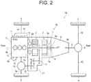
- FIG. 2 shows an example in which a straight engine is used as the engine 1.
- the engine 1 has a plurality of cylinders 1b.
- the cylinders 1b are disposed in one row in the direction of the rotational axis AL of the crankshaft 1a.
- the engine 1 when a straight engine is used as the engine 1, the engine 1 includes an intake system 1c that supplies air along with fuel to a combustion chamber (not shown) of the engine 1, and an exhaust system 1d that discharges exhaust gas resulting from combustion, as shown in FIG. 2 .
- the intake system 1c is connected to an intake side 1e of the engine 1 that is a side part of the engine 1 on one side in a width direction of the vehicle body (the lower side in FIG. 2 ).
- the exhaust system 1d is connected to an exhaust side If of the engine 1 that is a side part of the engine 1 on the other side in the width direction of the vehicle body (the upper side in FIG. 2 ).
- the engine 1 has the intake side 1e to which the intake system 1c is connected, and the exhaust side If which is the opposite side from the intake side 1e in the width direction of the vehicle body and to which the exhaust system 1d is connected.
- the first motor 2 is disposed on the output side of the engine 1 (the right side in FIG. 1 and FIG. 2 ), coaxially with the engine 1.
- the first motor 2 functions at least as an electricity generator that generates electricity by receiving and being driven by engine torque output by the engine 1.
- the first motor 2 functions also as a prime mover that outputs motor torque (first motor torque) by being supplied with and driven by electricity.
- the first motor 2 is a motor having an electricity generation function (so-called motor-generator), and is formed by, for example, a permanent-magnet synchronous motor or an induction motor.
- a battery (not shown) is connected to the first motor 2 through an inverter (not shown). It is therefore possible to drive the first motor 2 as an electricity generator and store the electricity generated during that time in the battery. It is also possible to supply electricity stored in the battery to the first motor 2 and drive the first motor 2 as a prime mover to output motor torque.
- the second motor 3 is disposed on the output side of the engine 1, coaxially with the engine 1 and the first motor 2. In the examples shown in FIG. 1 and FIG. 2 , the second motor 3 and the first motor 2 are disposed in this order from the side nearer to the engine 1 (the left side in FIG. 1 and FIG. 2 ) on a rotational axis of the engine 1, i.e., the rotational axis AL.
- the second motor 3 functions at least as a prime mover that outputs motor torque (second motor torque) by being supplied with and driven by electricity.
- the second motor 3 functions also as an electricity generator that generates electricity by receiving and being driven by torque from outside.
- the second motor 3 is a motor having an electricity generation function (so-called motor-generator), and is formed by, for example, a permanent-magnet synchronous motor or an induction motor.
- a battery (not shown) is connected to the second motor 3 through an inverter (not shown). It is therefore possible to supply electricity stored in the battery to the second motor 3 and drive the second motor 3 as a prime mover to output motor torque.
- the second motor 3 is coupled to the front wheels 5 so as to be able to transmit power. It is therefore also possible to drive the second motor 3 as an electricity generator by torque transmitted from the front wheels 5, and store regenerated electricity generated during that time in the battery.
- the first motor 2 and the second motor 3 are connected to each other through an inverter so as to be able to exchange electricity with each other. It is also possible, for example, to directly supply electricity generated by the first motor 2 to the second motor 3 and output motor torque by the second motor 3.
- the rear wheels 4 are driving wheels to which driving torque output by a driving power source is transmitted to generate driving power for the vehicle Ve.
- the rear wheels 4 are coupled to the engine 1 and the first motor 2 through the automatic transmission 6 and the starter clutch 7 to be described later, and through a rear propeller shaft 8, a rear differential gear 9, and a rear driving shaft 10.
- the front wheels 5 are driving wheels to which driving torque output by a driving power source is transmitted to generate driving power for the vehicle Ve.
- the front wheels 5 are coupled to the second motor 3 through the power transmission mechanism 11 to be described later, a front propeller shaft 12, a front differential gear 13, and a front driving shaft 14.
- the vehicle Ve is a four-wheel-drive vehicle or an all-wheel-drive vehicle in which driving torque is transmitted to both the front wheels 5 and the rear wheels 4 to generate driving power.
- the automatic transmission 6 is disposed on the output side of the engine 1, coaxially with the engine 1 and the first motor 2.
- the automatic transmission 6 is disposed on the output side of the first motor 2 (the right side in FIG. 1 and FIG. 2 ) on the rotational axis AL, and transmits torque between the engine 1 and the first motor 2 on one side and the rear wheels 4 on the other side.
- the automatic transmission 6 is a mechanism that can appropriately change the ratio of an input rotation speed to an output rotation speed, and is formed by an automatically controllable transmission, such as a conventional automatic transmission or a continuously variable transmission. More preferably, the automatic transmission 6 includes a clutch mechanism that is engaged to permit torque transmission and disengaged to interrupt torque transmission and set a neutral state.
- the starter clutch 7 is disposed on the output side of the engine 1, coaxially with the engine 1 and the first motor 2. In the examples shown in FIG. 1 and FIG. 2 , the starter clutch 7 is disposed between the first motor 2 and the automatic transmission 6 on the rotational axis AL. The starter clutch 7 selectively permits or interrupts power transmission by a rear wheel-side driving system 15 located between the engine 1 and the first motor 2 on one side and the rear wheels 4 on the other side. In the examples shown in FIG. 1 and FIG. 2 , the starter clutch 7 has a friction disc 7a coupled to a rotating member on the side of the engine 1 and the first motor 2, and a friction disc 7b coupled to a rotating member on the side of the rear wheels 4.
- the friction disc 7a of the starter clutch 7 is coupled to a rotating shaft 2a of the first motor 2.
- the rotating shaft 2a is coupled to the output shaft (crankshaft) 1a of the engine 1 through a damper 16.
- the output shaft 1a of the engine 1, the rotating shaft 2a of the first motor 2, and the friction disc 7a of the starter clutch 7 are coupled together.
- the friction disc 7b of the starter clutch 7 is coupled to an input shaft 6a of the automatic transmission 6.
- An output shaft 6b of the automatic transmission 6 is coupled to the rear wheels 4 through the rear propeller shaft 8, the rear differential gear 9, and the rear driving shaft 10.
- the friction disc 7b of the starter clutch 7 and the rear wheels 4 are coupled together through the automatic transmission 6 so as to be able to transmit power.
- the starter clutch 7 in the embodiment of the present invention can also be formed by a multiple-disc clutch which has a plurality of friction discs 7a and a plurality of friction disc 7b and in which the friction discs 7a and the friction discs 7b are alternately disposed.
- a friction clutch of which the torque transmission capacity can be continuously varied is used as the starter clutch 7 in the embodiment of the present invention. It is possible to smoothly transmit power by controlling the engagement state of the starter clutch 7 and continuously varying the torque transmission capacity of the starter clutch 7 when transmitting the engine torque of the engine 1 to the rear wheels 4. Or it is possible to smoothly start the vehicle Ve.
- the engine 1 and the first motor 2 are coupled together in the rear wheel-side driving system 15 as described above.
- This makes it possible to start the vehicle Ve by the engine torque of the engine 1 or smoothly transmit power without using the starter clutch 7.
- the starter clutch 7 can be used to absorb the difference in rotation speed and thereby allow for smoother power transmission.
- the second motor 3 is disposed between the engine 1 and the first motor 2 on the rotational axis AL of the driving power sources as described above.
- the second motor 3 is coupled to a driving system on the side of the front wheels 5 of the vehicle Ve, such that the motor torque output by the second motor 3 can be transmitted to the front wheels 5 to generate driving power.
- the second motor 3 is not coupled to the engine 1, the first motor 2, and the rear wheels 4, and does not transmit power to the engine 1, the first motor 2, and the rear wheels 4. In the examples shown in FIG. 1 and FIG.
- a rotating shaft 3a of the second motor 3 is formed as a hollow shaft, and the output shaft 1a of the engine 1 is inserted in a hollow part of the rotating shaft 3a so as to be able to rotate relative to the rotating shaft 3a.
- the second motor 3 is disposed coaxially with the engine 1 and the first motor 2 on the rotational axis AL.
- the second motor 3 is disconnected from the rear wheel-side driving system 15 between the engine 1 and the first motor 2 on one side and the rear wheels 4 on the other side, and does not transmit power to the engine 1, the first motor 2, and the rear wheels 4.
- the rotating shaft 3a of the second motor 3 is coupled to the front wheels 5 through the power transmission mechanism 11, the front propeller shaft 12, the front differential gear 13, and the front driving shaft 14.
- the motor torque output by the second motor 3 is transmitted to the front wheels 5 after being amplified by the power transmission mechanism 11 and the front differential gear 13.
- the second motor 3 constitutes a part of a front wheel-side driving system 17 that transmits power between the second motor 3 and the front wheels 5, along with the power transmission mechanism 11, the front propeller shaft 12, the front differential gear 13, the front driving shaft 14, etc.
- the front wheel-side driving system 17 is independent of the rear wheel-side driving system 15.
- the vehicle Ve with the engine 1 turned off, to generate driving power by transmitting the motor torque output by the second motor 3 to the front wheels 5. It is also possible, with the starter clutch 7 disengaged, to generate electricity by operating the engine 1 and driving the first motor 2 by the engine torque, as well as to generate driving power by transmitting the motor torque of the second motor 3 to the front wheels 5. Further, it is also possible, with the starter clutch 7 engaged, to generate driving power by operating the engine 1 and transmitting the engine torque to the rear wheels 4 and by transmitting the motor torque of the second motor 3 to the front wheels 5.
- the power transmission mechanism 11 is a transmission mechanism that varies the motor torque output by the second motor 3 and then transmits the motor torque to the front propeller shaft 12.
- the power transmission mechanism 11 is formed by a speed reducing gear pair.
- the power transmission mechanism 11 can be formed by a speed reducing mechanism combining a plurality of speed reducing gear pairs.
- a speed reducing mechanism that is composed of a chain power transmission mechanism, a plurality of speed reducing gear pairs, a switching clutch, etc. and varies speed in two stages is used as the power transmission mechanism 11.
- both the first motor 2 and the second motor 3 are disposed coaxially with the engine 1 that is longitudinally positioned on the front side of the vehicle Ve.
- the motors can be installed with high efficiency in an existing FR vehicle or an FR vehicle-based four-wheel-drive vehicle.
- the intake system 1c and the exhaust system 1d of the longitudinally positioned engine 1 are connected separately to the intake side 1e and the exhaust side If of the engine 1 in the width direction of the vehicle body as described above.
- the front propeller shaft 12 of the front wheel-side driving system 17 is disposed adjacent to the engine 1, on the intake side 1e of the engine 1 in the width direction of the vehicle body.
- the front propeller shaft 12 and the front wheel-side driving system 17 can be disposed by effectively using the space around the intake side 1e on the opposite side from the exhaust system Id, which includes an exhaust pipe and a catalyst, so as to avoid interference with the exhaust system 1d. It is possible to install particularly the front wheel-side driving system 17 with higher efficiency without making major changes to the vehicle body structure or layout of an existing vehicle.
- the second motor 3 is disposed nearer to the engine 1 in the front-rear direction of the vehicle Ve.
- the engine 1 is disposed in longitudinal position on the front side of the vehicle Ve (the left side in FIG. 1 and FIG. 2 ).
- the second motor 3 is disposed nearer to the front wheels 5 in the front-rear direction of the vehicle Ve than when the second motor 3 is disposed, for example, on the output side of the first motor 2.
- the distance between the second motor 3 and the front wheels 5 in the front wheel-side driving system 17 can be reduced.
- the length of the front propeller shaft 12 in the front wheel-side driving system 17 can be reduced.
- the size and weight of the driving unit can be reduced.
- shortening the front propeller shaft 12 can raise the natural frequency of a rotating and vibrating system including the front propeller shaft 12.
- resonance in the front wheel-side driving system 17 during normal travel can be reduced, and the NV performance of the vehicle Ve can be improved.
- the amount of torsion of the front propeller shaft 12 during power transmission can be reduced. As a result, the responsiveness of driving power in the front wheel-side driving system 17 can be improved.
- the configuration of the vehicle Ve in the embodiment of the present invention is not limited to the configurations shown in FIG. 1 and FIG. 2 .
- the configurations shown in FIG. 3 to FIG. 10 to be described below can also be adopted.
- those components that have the same configuration or function as in the vehicle Ve shown in FIG. 1 or FIG. 2 or the vehicle Ve shown in any one of the preceding drawings will be denoted by the same reference signs as in FIG. 1 or FIG. 2 or that preceding drawing.
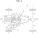
- the starter clutch 7 is disposed in a radially inner part of the first motor 2.
- a rotating shaft 2b of the first motor 2 has a hollowed shape, and the starter clutch 7 is disposed inside a hollow part of the rotating shaft 2b.
- the friction disc 7a of the starter clutch 7 is coupled to an end 2c of the rotating shaft 2b on the side nearer to the second motor 3 (the left side in FIG. 3 ).
- the friction disc 7b of the starter clutch 7 is coupled to the input shaft 6a of the automatic transmission 6 as described above.
- the input shaft 6a is inserted in the hollow part of the rotating shaft 2b so as to be able to rotate relative to the rotating shaft 2b.
- the starter clutch 7 is disposed coaxially with the engine 1, the first motor 2, and the second motor 3 on the rotational axis AL.
- the starter clutch 7 is disposed in the hollow part of the rotating shaft 2b of the first motor 2 as in the example shown in FIG. 3 , the overall length of the rear wheel-side driving system 15 from the engine 1 to the rear wheels 4 can be reduced. This makes it possible to avoid interference with, for example, a structure under the floor of the vehicle body, or increase the flexibility of installation in an existing vehicle body, when converting an existing vehicle body structure or layout. As a result, the motors can be installed with higher efficiency in an existing FR vehicle or an FR vehicle-based four-wheel-drive vehicle.
- the vehicle Ve shown in FIG. 4 is configured such that power transmission between the second motor 3 and the power transmission mechanism 11 is performed on the side of the second motor 3 nearer to the engine 1 (the left side in FIG. 4 ).
- a protrusion 3c protruding toward the engine 1 in the direction of the rotational axis AL is formed on an end 3b of the rotating shaft 3a of the second motor 3 on the side nearer to the engine 1.
- the protrusion 3c and the power transmission mechanism 11 are coupled together through a gear power transmission mechanism, a chain power transmission mechanism, or the like so as to be able to transmit power.
- the protrusion 3c and the power transmission mechanism 11 are coupled together through a chain power transmission mechanism 20.
- the protrusion 3c has a hollowed shape.
- the space inside the engine compartment can be effectively used to dispose the power transmission mechanism 11.
- the second motor 3 can be installed with higher efficiency in an existing FR vehicle or an FR vehicle-based four-wheel-drive vehicle.
- the first motor 2 and the second motor 3 are disposed in the order of the first motor 2 and the second motor 3 from the side nearer to the engine 1 (the left side in FIG. 5 ) on the rotational axis AL.
- the first motor 2 has a larger maximum outside diameter than the second motor 3.
- the first motor 2 and the second motor 3 are disposed in the order of one motor of the first motor 2 and the second motor 3 that has a larger maximum outside diameter (the first motor 2 in the example shown in FIG. 5 ) and the other motor that has a smaller maximum outside diameter (the second motor 3 in the example shown in FIG. 5 ), from the side nearer to the engine 1 in the front-rear direction of the vehicle Ve.
- the space inside the engine compartment can be effectively used to dispose the motor having a larger maximum outside diameter.
- the outer shapes (contours) of the hybrid driving unit having the engine 1, the first motor 2, and the second motor 3 as driving power sources can be made to conform to the shape of a floor tunnel of a common vehicle body.
- the motors can be installed with high efficiency in an existing FR vehicle or an FR vehicle-based four-wheel-drive vehicle.
- the starter clutch 7 is disposed in the hollow part of the rotating shaft 2b of the first motor 2. Therefore, the overall length of the rear wheel-side driving system 15 can be reduced.
- a clutch mechanism 6c provided inside the automatic transmission 6 functions as a starter clutch, and the starter clutch 7 is omitted.
- the automatic transmission 6 has the clutch mechanism 6c that selectively permits or interrupts power transmission between the input shaft 6a and the output shaft 6b of the automatic transmission 6.
- the clutch mechanism 6c is engaged to permit torque transmission and disengaged to interrupt torque transmission and set the automatic transmission 6 to a neutral state.
- the torque transmission capacity of the clutch mechanism 6c can be continuously varied.
- the clutch mechanism 6c of the automatic transmission 6 functions as a starter clutch as in the example shown in FIG. 6
- the starter clutch 7 can be omitted.
- the overall length of the rear wheel-side driving system 15 from the engine 1 to the rear wheels 4 can be reduced.
- the motors can be installed with higher efficiency in an existing FR vehicle or an FR vehicle-based four-wheel-drive vehicle.
- the vehicle Ve shown in FIG. 7 includes a chain speed reducing mechanism 30 that amplifies the output torque of the second motor 3 in two stages, between the engine 1 and the automatic transmission 6, between the second motor 3 and the front wheels 5.
- the chain speed reducing mechanism 30 is provided between the second motor 3 and the power transmission mechanism 11.
- the chain speed reducing mechanism 30 has a first chain speed reducing shaft 31, a second chain speed reducing shaft 32 having a lower rotation speed than the first chain speed reducing shaft 31, and a third chain speed reducing shaft 33 having a lower rotation speed than the second chain speed reducing shaft 32.
- the first chain speed reducing shaft 31 is formed so as to rotate integrally with the rotating shaft 3a of the second motor 3, and has a sprocket 31a mounted at a leading end (the end on the left side in FIG. 7 ).
- the second chain speed reducing shaft 32 is disposed parallel to the first chain speed reducing shaft 31 in the vehicle width direction, and has a sprocket 32a, having a larger diameter than the sprocket 31a, mounted at an end on one side (the right side in FIG. 7 ), and a sprocket 32b, having a smaller diameter than a sprocket 33a of the third chain speed reducing shaft 33 to be described later, mounted at an end on the other side (the left side in FIG. 7 ).
- the third chain speed reducing shaft 33 is formed so as to rotate integrally with an input shaft 11a of the power transmission mechanism 11, and has the sprocket 33a mounted at a leading end (the end on the right side in FIG. 7 ).
- a chain 34 is wound between the sprocket 31a and the sprocket 32a, and a chain 35 is wound between the sprocket 32b and the sprocket 33a.
- the second chain speed reducing shaft 32 has a lower rotation speed than the first chain speed reducing shaft 31.
- the third chain speed reducing shaft 33 has a lower rotation speed than the second chain speed reducing shaft 32.
- the chain speed reducing mechanism 30 amplifies the output torque of the second motor 3 in two stages between the second motor 3 and the front wheels 5.
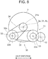
- the second chain speed reducing shaft 32 and the third chain speed reducing shaft 33 are disposed with the rotational axis AL therebetween, separately on both end sides in the width direction of the vehicle body (the up-down direction in FIG. 7 ).
- the second chain speed reducing shaft 32 and the third chain speed reducing shaft 33 are disposed on the opposite sides of the rotational axis AL.
- the chain speed reducing mechanism 30 that reduces the rotation speed of the second motor 3 in two stages is provided as in the example shown in FIG. 7 , the output torque of the second motor 3 can be significantly amplified before being transmitted to the front wheels 5. Accordingly, the second motor 3 can be downsized.
- the second chain speed reducing shaft 32 and the third chain speed reducing shaft 33 in the chain speed reducing mechanism 30 are disposed separately in the vehicle width direction.
- the chain speed reducing mechanism 30 having the three rotating shafts, the first chain speed reducing shaft 31, the second chain speed reducing shaft 32, and the third chain speed reducing shaft 33 can be compactly disposed in the width direction of the vehicle body.
- the space in the width direction of the vehicle body can be effectively used to dispose the chain speed reducing mechanism 30.
- a chain power transmission mechanism like the chain speed reducing mechanism 30 (also the chain power transmission mechanism 20) allows for a longer shaft-to-shaft distance between two rotating shafts that transmit torque to each other, which increases the flexibility of arrangement.
- the second motor 3 and the front wheel-side driving system 17 can be installed with higher efficiency in an existing FR vehicle or an FR vehicle-based four-wheel-drive vehicle.
- the vehicle Ve shown in FIG. 9 includes a speed reducing mechanism 40 that amplifies the output torque of the second motor 3 in two stages, between the engine 1 and the automatic transmission 6, between the second motor 3 and the front wheels 5.
- the speed reducing mechanism 40 is provided between the second motor 3 and the power transmission mechanism 11.
- the speed reducing mechanism 40 has a first speed reducing shaft 41, a second speed reducing shaft 42 having a lower rotation speed than the first speed reducing shaft 41, and a third speed reducing shaft 43 having a lower rotation speed than the second speed reducing shaft 42.
- the first speed reducing shaft 41 is formed so as to rotate integrally with the rotating shaft 3a of the second motor 3, and has a sprocket 41a mounted at a leading end (the end on the left side in FIG. 9 ).
- the second speed reducing shaft 42 is disposed parallel to the first speed reducing shaft 41 in the vehicle width direction, and has a sprocket 42a, having a larger diameter than the sprocket 41a, mounted at an end on one side (the right side in FIG. 9 ).
- a gear 42b having a smaller diameter than a gear 43a of the third speed reducing shaft 43 to be described later is mounted.
- the third speed reducing shaft 43 doubles as the input shaft 11a of the power transmission mechanism 11, and has the gear 43a mounted at a leading end (the end on the right side in FIG. 9 ).
- a chain 44 is wound between the sprocket 41a and the sprocket 42a.
- the gear 42b and the gear 43a mesh with each other. Accordingly, the second speed reducing shaft 42 has a lower rotation speed than the first speed reducing shaft 41.
- the third speed reducing shaft 43 has a lower rotation speed than the second speed reducing shaft 42.
- the speed reducing mechanism 40 amplifies the output torque of the second motor 3 in two stages between the second motor 3 and the front wheels 5.
- the third speed reducing shaft 43 is coupled, so as to be able to transmit power, to the front propeller shaft 12 that transmits power to the front wheels 5 through the front differential gear 13.
- the front differential gear 13 is a so-called final reduction gear on the side of the front wheels 5, and reduces the rotation speed of the front propeller shaft 12 when transmitting power from the front propeller shaft 12 to the front driving shaft 14. Therefore, the front propeller shaft 12 has a lower rotation speed than the third speed reducing shaft 43, and corresponds to the fourth speed reducing shaft as termed in the embodiment of the present invention.
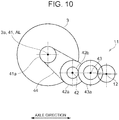
- the speed reducing mechanism 40 having four shafts in total is formed as shown in FIG. 10 .
- the speed reducing mechanism 40 is provided between the second motor 3 and the power transmission mechanism 11 to reduce the rotation speed of the second motor 3 in two stages.
- the speed reducing mechanism 40 has the four rotating shafts including the rotating shaft 3a of the second motor 3 and the front propeller shaft 12, between the second motor 3 and the front wheels 5, and of these rotating shafts, the fourth speed reducing shaft (front propeller shaft 12) located nearest to the front wheels and the front differential gear 13 that is the final reduction gear for the front wheels 5 are coupled together so as to be able to transmit power.
- the rotation speed of the second motor 3 can be reduced in three stages between the second motor 3 and the front wheels 5. Therefore, the output torque of the second motor 3 can be significantly amplified before being transmitted to the front wheels 5.
- the second motor 3 can be downsized and installed with higher efficiency in an existing FR vehicle or an FR vehicle-based four-wheel-drive vehicle.
- the hybrid vehicle of the present invention is configured as a four-wheel-drive vehicle or an all-wheel-drive vehicle which has the engine, the first motor, and the second motor as driving power sources and of which both the front and rear wheels are driven.
- the engine and the first motor are driving power sources in the rear wheel-side driving system and drive the rear wheels.
- the second motor is a driving power source in the front wheel-side driving system and drives the front wheels.
- the rear wheel-side driving system and the front wheel-side driving system are independent of each other, and no torque is transmitted between these two driving systems. This means that the second motor does not transmit torque to the front wheel-side driving system.
- a hybrid four-wheel-drive or all-wheel-drive vehicle is configured in which the first motor and the second motor are disposed coaxially with the longitudinally positioned engine and these engine and two motors serve as driving power sources.
- a two motor-type hybrid four-wheel-drive or all-wheel-drive vehicle without making major changes to the vehicle body structure or layout of an existing vehicle, such as a so-called FR vehicle of which the rear wheels are driven by an engine longitudinally positioned on the front side of the vehicle, or a four-wheel-drive vehicle based on such an FR vehicle.
- the hybrid vehicle of the present invention includes the starter clutch between the first motor and the rear wheels.
- the starter clutch is provided on the output side of the engine in the rear wheel-side driving system. It is possible to smoothly start the hybrid vehicle of the present invention by controlling the engagement state of this starter clutch when transmitting the engine torque to the rear wheels to start the vehicle. This can eliminate the need for a torque converter that is conventionally commonly used. Disengaging the starter clutch can disconnect the engine and the first motor from the rear wheel-side driving system. In this state, the hybrid vehicle can travel by the motor torque output by the second motor in the front wheel-side driving system. This means that the hybrid vehicle can travel also as an electric vehicle using the second motor as a driving power source.
- the hybrid vehicle of the present invention includes the automatic transmission between the first motor and the rear wheels.
- the automatic transmission is provided on the output side of the engine in the rear wheel-side driving system. It is possible to appropriately vary the engine speed by this automatic transmission and transmit the engine torque to the rear wheels to generate appropriate driving power.
- the clutch mechanism of the automatic transmission can function as the starter clutch as described above. This can eliminate the need for a starter clutch as described above and a torque converter.
- both the first motor and the second motor are disposed coaxially with the engine, and the second motor of these motors is disposed nearer to the engine in the front-rear direction of the vehicle.
- the engine is disposed in longitudinal position on the front side of the vehicle.
- the second motor is disposed nearer to the front wheels in the front-rear direction of the vehicle than when the second motor is disposed on the output side of the first motor.
- the distance between the second motor and the front wheels in the front wheel-side driving system 17 can be reduced, compared with when the second motor is disposed on the output side of the first motor.
- the length of the propeller shaft in the front wheel-side driving system 17 can be reduced.
- the size and weight can be reduced.
- the natural frequency of the rotating and vibrating system including the propeller shaft can be raised, so that it is possible to reduce resonance of the front wheel-side driving system during normal travel (during cruise or constant-speed travel) and improve the NV performance of the hybrid vehicle.
- the amount of torsion of the propeller shaft during power transmission can be reduced. As a result, the responsiveness of driving power in the front wheel-side driving system 17 can be improved.
- both the first motor and the second motor are disposed coaxially with the engine, and one of the first motor and the second motor that has a larger outside diameter is disposed nearer to the engine in the front-rear direction of the vehicle.
- the motors are disposed in the order of decreasing outside diameter on the output side of the engine that has generally the largest outside diameter in the driving unit.
- the space around the output side of the engine can be effectively used. Since the outside diameters of the motors can be made smaller in the direction away from the engine and toward the rear wheels, interference with an existing structure in a space under the vehicle floor can be avoided or reduced, and a space for occupants inside the vehicle cabin can be secured.
- the motors can be installed with high efficiency in an existing FR vehicle or an FR vehicle-based four-wheel-drive vehicle to configure the hybrid vehicle.
- the hybrid vehicle of the present invention includes the chain speed reducing mechanism between the second motor and the front wheels.
- the chain speed reducing mechanism has the three rotating shafts, the first chain speed reducing shaft, the second chain speed reducing shaft, and the third chain speed reducing shaft, between the second motor and the front wheels.
- the chain is wound around the sprocket mounted on each rotating shaft to form the chain speed reducing mechanism.
- the chain speed reducing mechanism that reduces the rotation speed of the second motor in two stages is composed of the chain power transmission mechanism in which the chain is wound between the first chain speed reducing shaft and the second chain speed reducing shaft and of a chain power transmission mechanism in which the chain is wound between the second chain speed reducing shaft and the third chain speed reducing shaft.
- the output torque of the second motor can be significantly amplified before being transmitted to the front wheels.
- the second motor can be downsized.
- the second chain speed reducing shaft and the third chain speed reducing shaft are disposed separately in the width direction of the vehicle body.
- the space in the width direction of the vehicle body can be effectively used and the second motor and the front wheel-side driving system can be installed with high efficiency to configure the hybrid vehicle.
- the hybrid vehicle of the present invention further includes the speed reducing mechanism between the second motor and the front wheels.
- This speed reducing mechanism is composed of, for example, a speed reducing gear pair and a chain power transmission mechanism, and reduces the rotation speed of the second motor in two stages.
- the speed reducing mechanism has four rotating shafts including the rotating shaft of the second motor, between the second motor and the front wheels, and of these rotating shafts, the fourth speed reducing shaft located nearest to the front wheels and the front wheel-side differential gear that is the final reduction gear for the front wheels are coupled together so as to be able to transmit power.
- the rotation speed of the second motor can be reduced in three stages between the second motor and the front wheels.
- the output torque of the second motor can be significantly amplified before being transmitted to the front wheels.
- the second motor can be downsized.
- the intake system and the exhaust system of the longitudinally positioned engine are respectively connected to both side parts of the engine in the width direction of the vehicle body, i.e., separately connected to the intake side and the exhaust side of the engine, as described above.
- the propeller shaft of the front wheel-side driving system is disposed adjacent to the engine, on the intake side of the engine in the width direction of the vehicle body.
Landscapes
- Engineering & Computer Science (AREA)
- Mechanical Engineering (AREA)
- Transportation (AREA)
- Chemical & Material Sciences (AREA)
- Combustion & Propulsion (AREA)
- General Engineering & Computer Science (AREA)
- Automation & Control Theory (AREA)
- Power Engineering (AREA)
- Hybrid Electric Vehicles (AREA)
- Electric Propulsion And Braking For Vehicles (AREA)
- Arrangement And Driving Of Transmission Devices (AREA)
- Arrangement Of Transmissions (AREA)
- Arrangement Or Mounting Of Propulsion Units For Vehicles (AREA)
Abstract
Description
- The present invention relates to a hybrid vehicle that is equipped with an engine and a motor having an electricity generation function as driving power sources, and that can be driven to travel by the front wheels and the rear wheels.
- Japanese Patent Application Publication No.
2016-2772 JP 2016-2772 A JP 2016-2772 A - As described above, in the hybrid vehicle described in
JP 2016-2772 A JP 2016-2772 A JP 2016-2772 A FIG. 2 ofJP 2016-2772 A JP 2016-2772 A FIG. 1 ofJP 2016-2772 A - While the hybrid vehicle described in
JP 2016-2772 A JP 2016-2772 A - In the hybrid vehicle described in
JP 2016-2772 A - The present invention provides a hybrid vehicle that uses an engine and two motors as driving power sources to drive both the front and rear wheels, by making as few changes as possible to the vehicle body structure or layout of an existing FR vehicle or an FR vehicle-based four-wheel-drive vehicle.
- The present invention is a hybrid vehicle including: an engine disposed on a front side of a vehicle body, in longitudinal position with a direction of a rotational axis of a crankshaft oriented along a front-rear direction of the vehicle body; an automatic transmission that is disposed coaxially with the engine and increases and decreases engine torque output by the engine; a first motor that functions to generate electricity by being driven by the engine torque; a rear wheel to which at least one of the engine torque and first motor torque output by the first motor is transmitted to generate driving power; a second motor that outputs second motor torque; and a front wheel to which the second motor torque is transmitted to generate driving power. Both the first motor and the second motor are disposed between the engine and the automatic transmission, coaxially with the engine and the automatic transmission. The first motor is coupled to the engine. A power transmission mechanism that increases and decreases the driving power of the front wheel is provided. The second motor is coupled to the power transmission mechanism without being coupled to the engine and the automatic transmission.
- In the present invention, a starter clutch that permits or interrupts torque transmission between the engine and the automatic transmission may be provided between the engine and the automatic transmission.
- In the present invention, the automatic transmission may have a clutch mechanism that permits or interrupts torque transmission between an input shaft and an output shaft of the automatic transmission.
- In the present invention, the first motor and the second motor may be disposed in the order of the second motor and the first motor from a side nearer to the engine in the front-rear direction.
- In the present invention, a transmission mechanism that varies the second motor torque and then transmits the second motor torque to the front wheel side may be provided between the second motor of a front wheel-side driving system and the front wheel.
- In the present invention, the first motor and the second motor may be different from each other in maximum outside diameter. The first motor and the second motor may be disposed in the order of one motor of the first motor and the second motor that has a larger maximum outside diameter and the other motor that has a smaller maximum outside diameter, from a side nearer to the engine in the front-rear direction.
- In the present invention, the power transmission mechanism may have a chain speed reducing mechanism that amplifies the second motor torque in two stages. The chain speed reducing mechanism may have a first chain speed reducing shaft that rotates integrally with a rotating shaft of the second motor, a second chain speed reducing shaft having a lower rotation speed than the first chain speed reducing shaft, and a third chain speed reducing shaft having a lower rotation speed than the second chain speed reducing shaft. The second chain speed reducing shaft and the third chain speed reducing shaft may be disposed on opposite sides of the rotational axis of the crankshaft in a width direction of the vehicle body.
- In the present invention, the power transmission mechanism may have a speed reducing mechanism that amplifies the second motor torque in two stages. The speed reducing mechanism may have a first speed reducing shaft that rotates integrally with a rotating shaft of the second motor, a second speed reducing shaft having a lower rotation speed than the first speed reducing shaft, and a third speed reducing shaft having a lower rotation speed than the second speed reducing shaft. The third speed reducing shaft may be coupled, so as to be able to transmit power, to a fourth speed reducing shaft that transmits torque to the front wheel through a front wheel-side differential gear coupled to the front wheel.
- In the present invention, the engine may be a straight engine having a plurality of cylinders disposed in one row in the direction of the rotational axis of the crankshaft. The engine may have an intake side to which an intake system is connected, and an exhaust side which is the opposite side from the intake side in a width direction of the vehicle body and to which an exhaust system is connected. The power transmission mechanism may have a front wheel-side differential gear that is coupled to the front wheel, and a front wheel-side propeller shaft that transmits torque between the second motor and the front wheel-side differential gear. The front wheel-side propeller shaft may be disposed on the intake side in the width direction, with a direction of a rotational axis of the front wheel-side propeller shaft oriented along the front-rear direction.
- Features, advantages, and technical and industrial significance of exemplary embodiments of the invention will be described below with reference to the accompanying drawings, in which like numerals denote like elements, and wherein:
-
FIG. 1 is a view showing an example (a configuration in which a second motor is disposed on a front side and a first motor is disposed on a rear side) of a hybrid vehicle that is the subject of the present invention; -
FIG. 2 is a view showing another example (a configuration in which a straight engine is installed) of the hybrid vehicle that is the subject of the present invention; -
FIG. 3 is a view showing another example (a configuration in which the second motor is disposed on the front side and the first motor is disposed on the rear side, and a starter clutch is disposed on a radially inner side of the first motor) of the hybrid vehicle that is the subject of the present invention; -
FIG. 4 is a view showing another example (a configuration in which the second motor is disposed on the front side and the first motor is disposed on the rear side, and a power transmission mechanism between the second motor and front wheels is disposed nearer to the front wheels) of the hybrid vehicle that is the subject of the present invention; -
FIG. 5 is a view showing another example (a configuration in which a large-diameter first motor is disposed on the front side and a small-diameter second motor is disposed on the rear side, and a starter clutch is disposed on a radially inner side of the first motor) of the hybrid vehicle that is the subject of the present invention; -
FIG. 6 is a view showing another example (a configuration in which the first motor is disposed on the front side and the second motor is disposed on the rear side, and a clutch mechanism of an automatic transmission disposed on an output side of the second motor functions as a starter clutch) of the hybrid vehicle that is the subject of the present invention; -
FIG. 7 is a view showing another example (a configuration in which the first motor is disposed on the front side and the second motor is disposed on the rear side, and a two-stage chain speed reducing mechanism is provided between the second motor and the front wheels) of the hybrid vehicle that is the subject of the present invention; -
FIG. 8 is a view of the configuration shown inFIG. 7 , as seen from the vehicle front side, showing the positional relationship among rotating shafts of the chain speed reducing mechanism; -
FIG. 9 is a view showing another example (a configuration in which the first motor is disposed on the front side and the second motor is disposed on the rear side, and a four-shaft speed reducing mechanism is provided between the second motor and the front wheels) of the hybrid vehicle that is the subject of the present invention; and -
FIG. 10 is a view of the configuration shown inFIG. 9 , as seen from the vehicle front side, showing the positional relationship among rotating shafts of the four-shaft speed reducing mechanism. - An embodiment of the present invention will be described with reference to the drawings. The embodiment to be shown below is merely an example of embodying the present invention and therefore does not limit the invention.
- A vehicle that is the subject of the embodiment of the present invention is a hybrid vehicle having an engine and first and second motors as driving power sources. The engine and the first motor are coupled to rear wheels so as to be able to transmit power. The first motor is disposed on an output side of the engine, and functions to generate electricity by receiving and being driven by engine torque output by the engine. The second motor is coupled to front wheels so as to be able to transmit power. Thus, the hybrid vehicle in the embodiment of the present invention is a four-wheel-drive (4WD) or all-wheel-drive (AWD) vehicle that can generate driving power by both the front and rear wheels. The second motor is not coupled to the engine, the first motor, and the rear wheels, and does not transmit torque to the engine, the first motor, and the rear wheels.
- All the driving power sources, i.e., the engine, the first motor, and the second motor, of the hybrid vehicle in the embodiment of the present invention are disposed coaxially. The engine is disposed on a front side of the vehicle, in so-called longitudinal position with the direction of a rotational axis of a crankshaft oriented along a front-rear direction of the vehicle. Thus, the hybrid vehicle in the embodiment of the present invention can be configured by converting or changing the existing vehicle body structure or layout of a rear-wheel-drive vehicle (FR vehicle) which has an engine disposed in longitudinal position on the front side of the vehicle and of which the rear wheels are driven, a four-wheel-drive vehicle based on such an FR vehicle, or other vehicles.
-
FIG. 1 shows a specific example of the hybrid vehicle in the embodiment of the present invention. A hybrid vehicle (hereinafter referred to as the vehicle) Ve shown inFIG. 1 has an engine (ENG) 1, a first motor (MG1) 2, and a second motor (MG2) 3 as driving power sources. The vehicle Ve has, as other main components, rear wheels (driving wheels) 4, front wheels (driving wheels) 5, an automatic transmission (AT) 6, and astarter clutch 7. - For example, the
engine 1 is an internal combustion engine, such as a gasoline engine or a diesel engine, and is configured such that the adjustment of output and the operating state including start and stop are electrically controlled. In the case of a gasoline engine, a throttle valve opening degree, a fuel supply amount or a fuel injection amount, execution and stop of ignition, ignition timing, etc. are electrically controlled. In the case of a diesel engine, a fuel injection amount, fuel injection timing, a throttle valve opening degree in an exhaust gas recirculation (EGR) system, etc. are electrically controlled. As described above, theengine 1 is disposed in so-called longitudinal position with the direction of a rotational axis AL of a crankshaft (or an output shaft) 1a oriented along the front-rear direction of the vehicle Ve (the right-left direction inFIG. 1 ). - Various types of engines with different arrangements of cylinders, for example, a straight engine, V-engine, and horizontally opposed engine, can be adopted as the
engine 1.FIG. 1 shows an example in which a V-engine is used as theengine 1.FIG. 2 shows an example in which a straight engine is used as theengine 1. In the example shown inFIG. 2 , theengine 1 has a plurality ofcylinders 1b. Thecylinders 1b are disposed in one row in the direction of the rotational axis AL of thecrankshaft 1a. In particular, when a straight engine is used as theengine 1, theengine 1 includes anintake system 1c that supplies air along with fuel to a combustion chamber (not shown) of theengine 1, and anexhaust system 1d that discharges exhaust gas resulting from combustion, as shown inFIG. 2 . Theintake system 1c is connected to anintake side 1e of theengine 1 that is a side part of theengine 1 on one side in a width direction of the vehicle body (the lower side inFIG. 2 ). Theexhaust system 1d is connected to an exhaust side If of theengine 1 that is a side part of theengine 1 on the other side in the width direction of the vehicle body (the upper side inFIG. 2 ). Thus, in the example of the straight engine shown inFIG. 2 , theengine 1 has theintake side 1e to which theintake system 1c is connected, and the exhaust side If which is the opposite side from theintake side 1e in the width direction of the vehicle body and to which theexhaust system 1d is connected. - The
first motor 2 is disposed on the output side of the engine 1 (the right side inFIG. 1 andFIG. 2 ), coaxially with theengine 1. Thefirst motor 2 functions at least as an electricity generator that generates electricity by receiving and being driven by engine torque output by theengine 1. In the vehicle Ve in the embodiment of the present invention, thefirst motor 2 functions also as a prime mover that outputs motor torque (first motor torque) by being supplied with and driven by electricity. Thus, thefirst motor 2 is a motor having an electricity generation function (so-called motor-generator), and is formed by, for example, a permanent-magnet synchronous motor or an induction motor. A battery (not shown) is connected to thefirst motor 2 through an inverter (not shown). It is therefore possible to drive thefirst motor 2 as an electricity generator and store the electricity generated during that time in the battery. It is also possible to supply electricity stored in the battery to thefirst motor 2 and drive thefirst motor 2 as a prime mover to output motor torque. - The
second motor 3 is disposed on the output side of theengine 1, coaxially with theengine 1 and thefirst motor 2. In the examples shown inFIG. 1 andFIG. 2 , thesecond motor 3 and thefirst motor 2 are disposed in this order from the side nearer to the engine 1 (the left side inFIG. 1 andFIG. 2 ) on a rotational axis of theengine 1, i.e., the rotational axis AL. Thesecond motor 3 functions at least as a prime mover that outputs motor torque (second motor torque) by being supplied with and driven by electricity. In the vehicle Ve in the embodiment of the present invention, thesecond motor 3 functions also as an electricity generator that generates electricity by receiving and being driven by torque from outside. Thus, like thefirst motor 2, thesecond motor 3 is a motor having an electricity generation function (so-called motor-generator), and is formed by, for example, a permanent-magnet synchronous motor or an induction motor. A battery (not shown) is connected to thesecond motor 3 through an inverter (not shown). It is therefore possible to supply electricity stored in the battery to thesecond motor 3 and drive thesecond motor 3 as a prime mover to output motor torque. As will be described later, thesecond motor 3 is coupled to thefront wheels 5 so as to be able to transmit power. It is therefore also possible to drive thesecond motor 3 as an electricity generator by torque transmitted from thefront wheels 5, and store regenerated electricity generated during that time in the battery. Thefirst motor 2 and thesecond motor 3 are connected to each other through an inverter so as to be able to exchange electricity with each other. It is also possible, for example, to directly supply electricity generated by thefirst motor 2 to thesecond motor 3 and output motor torque by thesecond motor 3. - The
rear wheels 4 are driving wheels to which driving torque output by a driving power source is transmitted to generate driving power for the vehicle Ve. In the examples shown inFIG. 1 andFIG. 2 , therear wheels 4 are coupled to theengine 1 and thefirst motor 2 through theautomatic transmission 6 and thestarter clutch 7 to be described later, and through arear propeller shaft 8, a reardifferential gear 9, and arear driving shaft 10. - Like the
rear wheels 4, thefront wheels 5 are driving wheels to which driving torque output by a driving power source is transmitted to generate driving power for the vehicle Ve. In the examples shown inFIG. 1 andFIG. 2 , thefront wheels 5 are coupled to thesecond motor 3 through thepower transmission mechanism 11 to be described later, afront propeller shaft 12, a frontdifferential gear 13, and afront driving shaft 14. Thus, the vehicle Ve is a four-wheel-drive vehicle or an all-wheel-drive vehicle in which driving torque is transmitted to both thefront wheels 5 and therear wheels 4 to generate driving power. - The
automatic transmission 6 is disposed on the output side of theengine 1, coaxially with theengine 1 and thefirst motor 2. In the examples shown inFIG. 1 andFIG. 2 , theautomatic transmission 6 is disposed on the output side of the first motor 2 (the right side inFIG. 1 andFIG. 2 ) on the rotational axis AL, and transmits torque between theengine 1 and thefirst motor 2 on one side and therear wheels 4 on the other side. In brief, theautomatic transmission 6 is a mechanism that can appropriately change the ratio of an input rotation speed to an output rotation speed, and is formed by an automatically controllable transmission, such as a conventional automatic transmission or a continuously variable transmission. More preferably, theautomatic transmission 6 includes a clutch mechanism that is engaged to permit torque transmission and disengaged to interrupt torque transmission and set a neutral state. - The
starter clutch 7 is disposed on the output side of theengine 1, coaxially with theengine 1 and thefirst motor 2. In the examples shown inFIG. 1 andFIG. 2 , thestarter clutch 7 is disposed between thefirst motor 2 and theautomatic transmission 6 on the rotational axis AL. Thestarter clutch 7 selectively permits or interrupts power transmission by a rear wheel-side driving system 15 located between theengine 1 and thefirst motor 2 on one side and therear wheels 4 on the other side. In the examples shown inFIG. 1 andFIG. 2 , thestarter clutch 7 has afriction disc 7a coupled to a rotating member on the side of theengine 1 and thefirst motor 2, and afriction disc 7b coupled to a rotating member on the side of therear wheels 4. When thefriction disc 7a and thefriction disc 7b of thestarter clutch 7 are engaged with each other, torque is transmitted by the rear wheel-side driving system 15. As thestarter clutch 7 is disengaged, theengine 1 and thefirst motor 2 are disconnected from the rear wheel-side driving system 15. As thestarter clutch 7 is engaged, theengine 1 and thefirst motor 2 are coupled to the rear wheel-side driving system 15. - The
friction disc 7a of thestarter clutch 7 is coupled to arotating shaft 2a of thefirst motor 2. Therotating shaft 2a is coupled to the output shaft (crankshaft) 1a of theengine 1 through adamper 16. Thus, theoutput shaft 1a of theengine 1, therotating shaft 2a of thefirst motor 2, and thefriction disc 7a of thestarter clutch 7 are coupled together. - On the other hand, the
friction disc 7b of thestarter clutch 7 is coupled to aninput shaft 6a of theautomatic transmission 6. Anoutput shaft 6b of theautomatic transmission 6 is coupled to therear wheels 4 through therear propeller shaft 8, the reardifferential gear 9, and therear driving shaft 10. Thus, thefriction disc 7b of thestarter clutch 7 and therear wheels 4 are coupled together through theautomatic transmission 6 so as to be able to transmit power. - Although this is not shown in
FIG. 1 andFIG. 2 , thestarter clutch 7 in the embodiment of the present invention can also be formed by a multiple-disc clutch which has a plurality offriction discs 7a and a plurality offriction disc 7b and in which thefriction discs 7a and thefriction discs 7b are alternately disposed. In brief, for example, a friction clutch of which the torque transmission capacity can be continuously varied is used as thestarter clutch 7 in the embodiment of the present invention. It is possible to smoothly transmit power by controlling the engagement state of thestarter clutch 7 and continuously varying the torque transmission capacity of thestarter clutch 7 when transmitting the engine torque of theengine 1 to therear wheels 4. Or it is possible to smoothly start the vehicle Ve. - In the vehicle Ve in the embodiment of the present invention, the
engine 1 and thefirst motor 2 are coupled together in the rear wheel-side driving system 15 as described above. This makes it possible to start the vehicle Ve by the engine torque of theengine 1 or smoothly transmit power without using thestarter clutch 7. For example, it is possible to start the vehicle Ve or smoothly transmit power without using thestarter clutch 7, by controlling so as to increase or decrease the engine torque by the first motor when transmitting the engine torque to therear wheels 4. However, when the vehicle travels steadily by the engine torque at an extremely low speed of, say, about 1 km per hour to 3 km per hour, a difference in rotation speed occurs between the idling speed of theengine 1 and the wheel speed. In such a case, thestarter clutch 7 can be used to absorb the difference in rotation speed and thereby allow for smoother power transmission. - In the vehicle Ve in the embodiment of the present invention, the
second motor 3 is disposed between theengine 1 and thefirst motor 2 on the rotational axis AL of the driving power sources as described above. Thesecond motor 3 is coupled to a driving system on the side of thefront wheels 5 of the vehicle Ve, such that the motor torque output by thesecond motor 3 can be transmitted to thefront wheels 5 to generate driving power. Thesecond motor 3 is not coupled to theengine 1, thefirst motor 2, and therear wheels 4, and does not transmit power to theengine 1, thefirst motor 2, and therear wheels 4. In the examples shown inFIG. 1 andFIG. 2 , arotating shaft 3a of thesecond motor 3 is formed as a hollow shaft, and theoutput shaft 1a of theengine 1 is inserted in a hollow part of therotating shaft 3a so as to be able to rotate relative to therotating shaft 3a. Thus, thesecond motor 3 is disposed coaxially with theengine 1 and thefirst motor 2 on the rotational axis AL. On the other hand, thesecond motor 3 is disconnected from the rear wheel-side driving system 15 between theengine 1 and thefirst motor 2 on one side and therear wheels 4 on the other side, and does not transmit power to theengine 1, thefirst motor 2, and therear wheels 4. - The
rotating shaft 3a of thesecond motor 3 is coupled to thefront wheels 5 through thepower transmission mechanism 11, thefront propeller shaft 12, the frontdifferential gear 13, and thefront driving shaft 14. The motor torque output by thesecond motor 3 is transmitted to thefront wheels 5 after being amplified by thepower transmission mechanism 11 and the frontdifferential gear 13. Thus, thesecond motor 3 constitutes a part of a front wheel-side driving system 17 that transmits power between thesecond motor 3 and thefront wheels 5, along with thepower transmission mechanism 11, thefront propeller shaft 12, the frontdifferential gear 13, thefront driving shaft 14, etc. The front wheel-side driving system 17 is independent of the rear wheel-side driving system 15. - It is possible for the vehicle Ve, with the
engine 1 turned off, to generate driving power by transmitting the motor torque output by thesecond motor 3 to thefront wheels 5. It is also possible, with thestarter clutch 7 disengaged, to generate electricity by operating theengine 1 and driving thefirst motor 2 by the engine torque, as well as to generate driving power by transmitting the motor torque of thesecond motor 3 to thefront wheels 5. Further, it is also possible, with thestarter clutch 7 engaged, to generate driving power by operating theengine 1 and transmitting the engine torque to therear wheels 4 and by transmitting the motor torque of thesecond motor 3 to thefront wheels 5. - The
power transmission mechanism 11 is a transmission mechanism that varies the motor torque output by thesecond motor 3 and then transmits the motor torque to thefront propeller shaft 12. For example, thepower transmission mechanism 11 is formed by a speed reducing gear pair. Alternatively, thepower transmission mechanism 11 can be formed by a speed reducing mechanism combining a plurality of speed reducing gear pairs. In the examples shown inFIG. 1 andFIG. 2 , a speed reducing mechanism that is composed of a chain power transmission mechanism, a plurality of speed reducing gear pairs, a switching clutch, etc. and varies speed in two stages is used as thepower transmission mechanism 11. - As described above, in the vehicle Ve in the embodiment of the present invention, both the
first motor 2 and thesecond motor 3 are disposed coaxially with theengine 1 that is longitudinally positioned on the front side of the vehicle Ve. Thus, the motors can be installed with high efficiency in an existing FR vehicle or an FR vehicle-based four-wheel-drive vehicle. - In the vehicle Ve using a straight engine as shown in
FIG. 2 , theintake system 1c and theexhaust system 1d of the longitudinally positionedengine 1 are connected separately to theintake side 1e and the exhaust side If of theengine 1 in the width direction of the vehicle body as described above. Thefront propeller shaft 12 of the front wheel-side driving system 17 is disposed adjacent to theengine 1, on theintake side 1e of theengine 1 in the width direction of the vehicle body. Thus, thefront propeller shaft 12 and the front wheel-side driving system 17 can be disposed by effectively using the space around theintake side 1e on the opposite side from the exhaust system Id, which includes an exhaust pipe and a catalyst, so as to avoid interference with theexhaust system 1d. It is possible to install particularly the front wheel-side driving system 17 with higher efficiency without making major changes to the vehicle body structure or layout of an existing vehicle. - In the vehicle Ve shown in
FIG. 1 andFIG. 2 , thesecond motor 3 is disposed nearer to theengine 1 in the front-rear direction of the vehicle Ve. Theengine 1 is disposed in longitudinal position on the front side of the vehicle Ve (the left side inFIG. 1 andFIG. 2 ). In other words, thesecond motor 3 is disposed nearer to thefront wheels 5 in the front-rear direction of the vehicle Ve than when thesecond motor 3 is disposed, for example, on the output side of thefirst motor 2. In the vehicle Ve shown inFIG. 1 andFIG. 2 , therefore, the distance between thesecond motor 3 and thefront wheels 5 in the front wheel-side driving system 17 can be reduced. For example, the length of thefront propeller shaft 12 in the front wheel-side driving system 17 can be reduced. As thefront propeller shaft 12 is shortened, the size and weight of the driving unit can be reduced. Moreover, shortening thefront propeller shaft 12 can raise the natural frequency of a rotating and vibrating system including thefront propeller shaft 12. As a result, for example, resonance in the front wheel-side driving system 17 during normal travel (during cruise or constant-speed travel) can be reduced, and the NV performance of the vehicle Ve can be improved. In addition, the amount of torsion of thefront propeller shaft 12 during power transmission can be reduced. As a result, the responsiveness of driving power in the front wheel-side driving system 17 can be improved. - The configuration of the vehicle Ve in the embodiment of the present invention is not limited to the configurations shown in
FIG. 1 andFIG. 2 . For example, the configurations shown inFIG. 3 to FIG. 10 to be described below can also be adopted. In the vehicle Ve shown in these drawings, those components that have the same configuration or function as in the vehicle Ve shown inFIG. 1 orFIG. 2 or the vehicle Ve shown in any one of the preceding drawings will be denoted by the same reference signs as inFIG. 1 orFIG. 2 or that preceding drawing. - In the vehicle Ve shown in
FIG. 3 , thestarter clutch 7 is disposed in a radially inner part of thefirst motor 2. Specifically, in the example shown inFIG. 3 , arotating shaft 2b of thefirst motor 2 has a hollowed shape, and thestarter clutch 7 is disposed inside a hollow part of therotating shaft 2b. Thefriction disc 7a of thestarter clutch 7 is coupled to anend 2c of therotating shaft 2b on the side nearer to the second motor 3 (the left side inFIG. 3 ). Thefriction disc 7b of thestarter clutch 7 is coupled to theinput shaft 6a of theautomatic transmission 6 as described above. Theinput shaft 6a is inserted in the hollow part of therotating shaft 2b so as to be able to rotate relative to therotating shaft 2b. Thus, thestarter clutch 7 is disposed coaxially with theengine 1, thefirst motor 2, and thesecond motor 3 on the rotational axis AL. - If the
starter clutch 7 is disposed in the hollow part of therotating shaft 2b of thefirst motor 2 as in the example shown inFIG. 3 , the overall length of the rear wheel-side driving system 15 from theengine 1 to therear wheels 4 can be reduced. This makes it possible to avoid interference with, for example, a structure under the floor of the vehicle body, or increase the flexibility of installation in an existing vehicle body, when converting an existing vehicle body structure or layout. As a result, the motors can be installed with higher efficiency in an existing FR vehicle or an FR vehicle-based four-wheel-drive vehicle. - The vehicle Ve shown in
FIG. 4 is configured such that power transmission between thesecond motor 3 and thepower transmission mechanism 11 is performed on the side of thesecond motor 3 nearer to the engine 1 (the left side inFIG. 4 ). Specifically, in the example shown inFIG. 4 , aprotrusion 3c protruding toward theengine 1 in the direction of the rotational axis AL is formed on anend 3b of therotating shaft 3a of thesecond motor 3 on the side nearer to theengine 1. Theprotrusion 3c and thepower transmission mechanism 11 are coupled together through a gear power transmission mechanism, a chain power transmission mechanism, or the like so as to be able to transmit power. In the example shown inFIG. 4 , theprotrusion 3c and thepower transmission mechanism 11 are coupled together through a chainpower transmission mechanism 20. Like therotating shaft 3a, theprotrusion 3c has a hollowed shape. - If the vehicle Ve is configured such that power transmission between the
second motor 3 and thepower transmission mechanism 11 is performed on the side of thesecond motor 3 nearer to theengine 1 as in the example shown inFIG. 4 , the space inside the engine compartment can be effectively used to dispose thepower transmission mechanism 11. Thus, thesecond motor 3 can be installed with higher efficiency in an existing FR vehicle or an FR vehicle-based four-wheel-drive vehicle. - In the vehicle Ve shown in
FIG. 5 , thefirst motor 2 and thesecond motor 3 are disposed in the order of thefirst motor 2 and thesecond motor 3 from the side nearer to the engine 1 (the left side inFIG. 5 ) on the rotational axis AL. In the example shown inFIG. 5 , thefirst motor 2 has a larger maximum outside diameter than thesecond motor 3. Thus, in the vehicle Ve shown inFIG. 5 , thefirst motor 2 and thesecond motor 3 are disposed in the order of one motor of thefirst motor 2 and thesecond motor 3 that has a larger maximum outside diameter (thefirst motor 2 in the example shown inFIG. 5 ) and the other motor that has a smaller maximum outside diameter (thesecond motor 3 in the example shown inFIG. 5 ), from the side nearer to theengine 1 in the front-rear direction of the vehicle Ve. - If one of two motors installed as driving power sources that has a larger maximum outside diameter is disposed on the side nearer to the
engine 1 as in the example shown inFIG. 5 , the space inside the engine compartment can be effectively used to dispose the motor having a larger maximum outside diameter. Moreover, the outer shapes (contours) of the hybrid driving unit having theengine 1, thefirst motor 2, and thesecond motor 3 as driving power sources can be made to conform to the shape of a floor tunnel of a common vehicle body. Thus, the motors can be installed with high efficiency in an existing FR vehicle or an FR vehicle-based four-wheel-drive vehicle. As in the example shown inFIG. 3 , so in the vehicle Ve shown inFIG. 5 , thestarter clutch 7 is disposed in the hollow part of therotating shaft 2b of thefirst motor 2. Therefore, the overall length of the rear wheel-side driving system 15 can be reduced. - In the vehicle Ve shown in
FIG. 6 , aclutch mechanism 6c provided inside theautomatic transmission 6 functions as a starter clutch, and thestarter clutch 7 is omitted. Specifically, in the example shown inFIG. 6 , theautomatic transmission 6 has theclutch mechanism 6c that selectively permits or interrupts power transmission between theinput shaft 6a and theoutput shaft 6b of theautomatic transmission 6. Theclutch mechanism 6c is engaged to permit torque transmission and disengaged to interrupt torque transmission and set theautomatic transmission 6 to a neutral state. The torque transmission capacity of theclutch mechanism 6c can be continuously varied. - If the
clutch mechanism 6c of theautomatic transmission 6 functions as a starter clutch as in the example shown inFIG. 6 , thestarter clutch 7 can be omitted. Thus, the overall length of the rear wheel-side driving system 15 from theengine 1 to therear wheels 4 can be reduced. As a result, the motors can be installed with higher efficiency in an existing FR vehicle or an FR vehicle-based four-wheel-drive vehicle. - The vehicle Ve shown in
FIG. 7 includes a chainspeed reducing mechanism 30 that amplifies the output torque of thesecond motor 3 in two stages, between theengine 1 and theautomatic transmission 6, between thesecond motor 3 and thefront wheels 5. Specifically, in the example shown inFIG. 7 , the chainspeed reducing mechanism 30 is provided between thesecond motor 3 and thepower transmission mechanism 11. The chainspeed reducing mechanism 30 has a first chainspeed reducing shaft 31, a second chainspeed reducing shaft 32 having a lower rotation speed than the first chainspeed reducing shaft 31, and a third chainspeed reducing shaft 33 having a lower rotation speed than the second chainspeed reducing shaft 32. The first chainspeed reducing shaft 31 is formed so as to rotate integrally with therotating shaft 3a of thesecond motor 3, and has asprocket 31a mounted at a leading end (the end on the left side inFIG. 7 ). The second chainspeed reducing shaft 32 is disposed parallel to the first chainspeed reducing shaft 31 in the vehicle width direction, and has asprocket 32a, having a larger diameter than thesprocket 31a, mounted at an end on one side (the right side inFIG. 7 ), and asprocket 32b, having a smaller diameter than asprocket 33a of the third chainspeed reducing shaft 33 to be described later, mounted at an end on the other side (the left side inFIG. 7 ). The third chainspeed reducing shaft 33 is formed so as to rotate integrally with aninput shaft 11a of thepower transmission mechanism 11, and has thesprocket 33a mounted at a leading end (the end on the right side inFIG. 7 ). Achain 34 is wound between thesprocket 31a and thesprocket 32a, and achain 35 is wound between thesprocket 32b and thesprocket 33a. Accordingly, the second chainspeed reducing shaft 32 has a lower rotation speed than the first chainspeed reducing shaft 31. The third chainspeed reducing shaft 33 has a lower rotation speed than the second chainspeed reducing shaft 32. Thus, the chainspeed reducing mechanism 30 amplifies the output torque of thesecond motor 3 in two stages between thesecond motor 3 and thefront wheels 5. - In the vehicle Ve shown in
FIG. 7 , the second chainspeed reducing shaft 32 and the third chainspeed reducing shaft 33 are disposed with the rotational axis AL therebetween, separately on both end sides in the width direction of the vehicle body (the up-down direction inFIG. 7 ). In other words, the second chainspeed reducing shaft 32 and the third chainspeed reducing shaft 33 are disposed on the opposite sides of the rotational axis AL. - If the chain
speed reducing mechanism 30 that reduces the rotation speed of thesecond motor 3 in two stages is provided as in the example shown inFIG. 7 , the output torque of thesecond motor 3 can be significantly amplified before being transmitted to thefront wheels 5. Accordingly, thesecond motor 3 can be downsized. The second chainspeed reducing shaft 32 and the third chainspeed reducing shaft 33 in the chainspeed reducing mechanism 30 are disposed separately in the vehicle width direction. Thus, as shown inFIG. 8 , the chainspeed reducing mechanism 30 having the three rotating shafts, the first chainspeed reducing shaft 31, the second chainspeed reducing shaft 32, and the third chainspeed reducing shaft 33, can be compactly disposed in the width direction of the vehicle body. Moreover, the space in the width direction of the vehicle body can be effectively used to dispose the chainspeed reducing mechanism 30. Furthermore, compared with a gear power transmission mechanism, for example, a chain power transmission mechanism like the chain speed reducing mechanism 30 (also the chain power transmission mechanism 20) allows for a longer shaft-to-shaft distance between two rotating shafts that transmit torque to each other, which increases the flexibility of arrangement. Thus, thesecond motor 3 and the front wheel-side driving system 17 can be installed with higher efficiency in an existing FR vehicle or an FR vehicle-based four-wheel-drive vehicle. - The vehicle Ve shown in
FIG. 9 includes aspeed reducing mechanism 40 that amplifies the output torque of thesecond motor 3 in two stages, between theengine 1 and theautomatic transmission 6, between thesecond motor 3 and thefront wheels 5. Specifically, in the example shown inFIG. 9 , thespeed reducing mechanism 40 is provided between thesecond motor 3 and thepower transmission mechanism 11. Thespeed reducing mechanism 40 has a firstspeed reducing shaft 41, a secondspeed reducing shaft 42 having a lower rotation speed than the firstspeed reducing shaft 41, and a thirdspeed reducing shaft 43 having a lower rotation speed than the secondspeed reducing shaft 42. The firstspeed reducing shaft 41 is formed so as to rotate integrally with therotating shaft 3a of thesecond motor 3, and has asprocket 41a mounted at a leading end (the end on the left side inFIG. 9 ). The secondspeed reducing shaft 42 is disposed parallel to the firstspeed reducing shaft 41 in the vehicle width direction, and has asprocket 42a, having a larger diameter than thesprocket 41a, mounted at an end on one side (the right side inFIG. 9 ). At an end of the secondspeed reducing shaft 42 on the other side (the left side inFIG. 9 ), agear 42b having a smaller diameter than agear 43a of the thirdspeed reducing shaft 43 to be described later is mounted. The thirdspeed reducing shaft 43 doubles as theinput shaft 11a of thepower transmission mechanism 11, and has thegear 43a mounted at a leading end (the end on the right side inFIG. 9 ). Achain 44 is wound between thesprocket 41a and thesprocket 42a. Thegear 42b and thegear 43a mesh with each other. Accordingly, the secondspeed reducing shaft 42 has a lower rotation speed than the firstspeed reducing shaft 41. The thirdspeed reducing shaft 43 has a lower rotation speed than the secondspeed reducing shaft 42. Thus, thespeed reducing mechanism 40 amplifies the output torque of thesecond motor 3 in two stages between thesecond motor 3 and thefront wheels 5. - In the vehicle Ve shown in
FIG. 9 , the thirdspeed reducing shaft 43 is coupled, so as to be able to transmit power, to thefront propeller shaft 12 that transmits power to thefront wheels 5 through the frontdifferential gear 13. The frontdifferential gear 13 is a so-called final reduction gear on the side of thefront wheels 5, and reduces the rotation speed of thefront propeller shaft 12 when transmitting power from thefront propeller shaft 12 to thefront driving shaft 14. Therefore, thefront propeller shaft 12 has a lower rotation speed than the thirdspeed reducing shaft 43, and corresponds to the fourth speed reducing shaft as termed in the embodiment of the present invention. Thus, in the vehicle Ve shown inFIG. 9 , thespeed reducing mechanism 40 having four shafts in total is formed as shown inFIG. 10 . - Thus, in the vehicle Ve shown in
FIG. 9 , thespeed reducing mechanism 40 is provided between thesecond motor 3 and thepower transmission mechanism 11 to reduce the rotation speed of thesecond motor 3 in two stages. Thespeed reducing mechanism 40 has the four rotating shafts including therotating shaft 3a of thesecond motor 3 and thefront propeller shaft 12, between thesecond motor 3 and thefront wheels 5, and of these rotating shafts, the fourth speed reducing shaft (front propeller shaft 12) located nearest to the front wheels and the frontdifferential gear 13 that is the final reduction gear for thefront wheels 5 are coupled together so as to be able to transmit power. Thus, the rotation speed of thesecond motor 3 can be reduced in three stages between thesecond motor 3 and thefront wheels 5. Therefore, the output torque of thesecond motor 3 can be significantly amplified before being transmitted to thefront wheels 5. By extension, thesecond motor 3 can be downsized and installed with higher efficiency in an existing FR vehicle or an FR vehicle-based four-wheel-drive vehicle. - The operational effects of the present invention will be described. The hybrid vehicle of the present invention is configured as a four-wheel-drive vehicle or an all-wheel-drive vehicle which has the engine, the first motor, and the second motor as driving power sources and of which both the front and rear wheels are driven. The engine and the first motor are driving power sources in the rear wheel-side driving system and drive the rear wheels. The second motor is a driving power source in the front wheel-side driving system and drives the front wheels. The rear wheel-side driving system and the front wheel-side driving system are independent of each other, and no torque is transmitted between these two driving systems. This means that the second motor does not transmit torque to the front wheel-side driving system. On the other hand, the second motor is disposed on the rotational axis of the crankshaft of the engine along with the first motor. According to the present invention, therefore, a hybrid four-wheel-drive or all-wheel-drive vehicle is configured in which the first motor and the second motor are disposed coaxially with the longitudinally positioned engine and these engine and two motors serve as driving power sources. Thus, it is possible to configure a two motor-type hybrid four-wheel-drive or all-wheel-drive vehicle without making major changes to the vehicle body structure or layout of an existing vehicle, such as a so-called FR vehicle of which the rear wheels are driven by an engine longitudinally positioned on the front side of the vehicle, or a four-wheel-drive vehicle based on such an FR vehicle.
- The hybrid vehicle of the present invention includes the starter clutch between the first motor and the rear wheels. Specifically, the starter clutch is provided on the output side of the engine in the rear wheel-side driving system. It is possible to smoothly start the hybrid vehicle of the present invention by controlling the engagement state of this starter clutch when transmitting the engine torque to the rear wheels to start the vehicle. This can eliminate the need for a torque converter that is conventionally commonly used. Disengaging the starter clutch can disconnect the engine and the first motor from the rear wheel-side driving system. In this state, the hybrid vehicle can travel by the motor torque output by the second motor in the front wheel-side driving system. This means that the hybrid vehicle can travel also as an electric vehicle using the second motor as a driving power source.
- The hybrid vehicle of the present invention includes the automatic transmission between the first motor and the rear wheels. Specifically, the automatic transmission is provided on the output side of the engine in the rear wheel-side driving system. It is possible to appropriately vary the engine speed by this automatic transmission and transmit the engine torque to the rear wheels to generate appropriate driving power. Moreover, in the hybrid vehicle of the present invention, the clutch mechanism of the automatic transmission can function as the starter clutch as described above. This can eliminate the need for a starter clutch as described above and a torque converter.
- In the hybrid vehicle of the present invention, both the first motor and the second motor are disposed coaxially with the engine, and the second motor of these motors is disposed nearer to the engine in the front-rear direction of the vehicle. The engine is disposed in longitudinal position on the front side of the vehicle. Thus, the second motor is disposed nearer to the front wheels in the front-rear direction of the vehicle than when the second motor is disposed on the output side of the first motor. In the hybrid vehicle of the present invention, therefore, the distance between the second motor and the front wheels in the front wheel-
side driving system 17 can be reduced, compared with when the second motor is disposed on the output side of the first motor. For example, the length of the propeller shaft in the front wheel-side driving system 17 can be reduced. As the propeller shaft is shortened, the size and weight can be reduced. Moreover, the natural frequency of the rotating and vibrating system including the propeller shaft can be raised, so that it is possible to reduce resonance of the front wheel-side driving system during normal travel (during cruise or constant-speed travel) and improve the NV performance of the hybrid vehicle. In addition, the amount of torsion of the propeller shaft during power transmission can be reduced. As a result, the responsiveness of driving power in the front wheel-side driving system 17 can be improved. - In the hybrid vehicle of the present invention, both the first motor and the second motor are disposed coaxially with the engine, and one of the first motor and the second motor that has a larger outside diameter is disposed nearer to the engine in the front-rear direction of the vehicle. In the hybrid vehicle of the present invention, therefore, the motors are disposed in the order of decreasing outside diameter on the output side of the engine that has generally the largest outside diameter in the driving unit. Thus, the space around the output side of the engine can be effectively used. Since the outside diameters of the motors can be made smaller in the direction away from the engine and toward the rear wheels, interference with an existing structure in a space under the vehicle floor can be avoided or reduced, and a space for occupants inside the vehicle cabin can be secured. Thus, the motors can be installed with high efficiency in an existing FR vehicle or an FR vehicle-based four-wheel-drive vehicle to configure the hybrid vehicle.
- The hybrid vehicle of the present invention includes the chain speed reducing mechanism between the second motor and the front wheels. The chain speed reducing mechanism has the three rotating shafts, the first chain speed reducing shaft, the second chain speed reducing shaft, and the third chain speed reducing shaft, between the second motor and the front wheels. The chain is wound around the sprocket mounted on each rotating shaft to form the chain speed reducing mechanism. Specifically, the chain speed reducing mechanism that reduces the rotation speed of the second motor in two stages is composed of the chain power transmission mechanism in which the chain is wound between the first chain speed reducing shaft and the second chain speed reducing shaft and of a chain power transmission mechanism in which the chain is wound between the second chain speed reducing shaft and the third chain speed reducing shaft. Thus, in the hybrid vehicle of the present invention, the output torque of the second motor can be significantly amplified before being transmitted to the front wheels. By extension, the second motor can be downsized. In the hybrid vehicle of the present invention, the second chain speed reducing shaft and the third chain speed reducing shaft are disposed separately in the width direction of the vehicle body. Thus, the space in the width direction of the vehicle body can be effectively used and the second motor and the front wheel-side driving system can be installed with high efficiency to configure the hybrid vehicle.
- The hybrid vehicle of the present invention further includes the speed reducing mechanism between the second motor and the front wheels. This speed reducing mechanism is composed of, for example, a speed reducing gear pair and a chain power transmission mechanism, and reduces the rotation speed of the second motor in two stages. The speed reducing mechanism has four rotating shafts including the rotating shaft of the second motor, between the second motor and the front wheels, and of these rotating shafts, the fourth speed reducing shaft located nearest to the front wheels and the front wheel-side differential gear that is the final reduction gear for the front wheels are coupled together so as to be able to transmit power. Thus, the rotation speed of the second motor can be reduced in three stages between the second motor and the front wheels. In the hybrid vehicle of the present invention, therefore, the output torque of the second motor can be significantly amplified before being transmitted to the front wheels. By extension, the second motor can be downsized.
- When the hybrid vehicle of the present invention employs a straight engine as the engine serving as a driving power source, the intake system and the exhaust system of the longitudinally positioned engine are respectively connected to both side parts of the engine in the width direction of the vehicle body, i.e., separately connected to the intake side and the exhaust side of the engine, as described above. The propeller shaft of the front wheel-side driving system is disposed adjacent to the engine, on the intake side of the engine in the width direction of the vehicle body. Thus, it is possible to dispose the front wheel-side propeller shaft and the front wheel-side driving system by effectively using the space around the intake side on the opposite side from the exhaust system, which includes the exhaust pipe and the catalyst, so as to avoid interference with the exhaust system. It is therefore possible to install particularly the front wheel-side driving system with high efficiency to configure the hybrid vehicle, without making major changes to the vehicle body structure or layout of an existing vehicle.
Claims (9)
- A hybrid vehicle comprising:an engine (1) disposed on a front side of a vehicle body, in longitudinal position with a direction of a rotational axis of a crankshaft (1a) oriented along a front-rear direction of the vehicle body;an automatic transmission (6) that is disposed coaxially with the engine (1), and increases and decreases engine torque output by the engine (1);a first motor (2) that functions to generate electricity by being driven by the engine torque;a rear wheel (4) to which at least one of the engine torque and first motor torque output by the first motor (2) is transmitted to generate driving power;a second motor (3) that outputs second motor torque;a front wheel (5) to which the second motor torque is transmitted to generate driving power; anda power transmission mechanism (11) that increases and decreases the driving power of the front wheel (5), whereinboth the first motor (2) and the second motor (3) are disposed between the engine (1) and the automatic transmission (6), coaxially with the engine (1) and the automatic transmission (6),the first motor (2) is coupled to the engine (1), andthe second motor (3) is coupled to the power transmission mechanism (11) without being coupled to the engine (1) and the automatic transmission (6).
- The hybrid vehicle according to claim 1, wherein a starter clutch (7) that permits or interrupts torque transmission between the engine (1) and the automatic transmission (6) is provided between the engine (1) and the automatic transmission (6).
- The hybrid vehicle according to claim 1 or 2, wherein the automatic transmission (6) has a clutch mechanism that permits or interrupts torque transmission between an input shaft (6a) and an output shaft (6b) of the automatic transmission (6).
- The hybrid vehicle according to any one of claims 1 to 3, wherein the first motor (2) and the second motor (3) are disposed in order of the second motor (3) and the first motor (2) from a side nearer to the engine (1) in the front-rear direction.
- The hybrid vehicle according to any one of claims 1 to 4, wherein
the first motor (2) and the second motor (3) are different from each other in maximum outside diameter, and
the first motor (2) and the second motor (3) are disposed in order of one motor of the first motor (2) and the second motor (3) that has a larger maximum outside diameter and the other motor that has a smaller maximum outside diameter, from a side nearer to the engine (1) in the front-rear direction. - The hybrid vehicle according to any one of claims 1 to 5, wherein
the power transmission mechanism (11) has a chain speed reducing mechanism (30) that amplifies the second motor torque in two stages,
the chain speed reducing mechanism (30) has a first chain speed reducing shaft (31) that rotates integrally with a rotating shaft (3a) of the second motor (3), a second chain speed reducing shaft (32) having a lower rotation speed than the first chain speed reducing shaft (31), and a third chain speed reducing shaft (33) having a lower rotation speed than the second chain speed reducing shaft (32), and
the second chain speed reducing shaft (32) and the third chain speed reducing shaft (33) are disposed on opposite sides of the rotational axis of the crankshaft (1a) in a width direction of the vehicle body. - The hybrid vehicle according to any one of claims 1 to 5, wherein
the power transmission mechanism (11) has a speed reducing mechanism (40) that amplifies the second motor torque in two stages,
the speed reducing mechanism (40) has a first speed reducing shaft (41) that rotates integrally with a rotating shaft (3a) of the second motor (3), a second speed reducing shaft (42) having a lower rotation speed than the first speed reducing shaft (41), and a third speed reducing shaft (43) having a lower rotation speed than the second speed reducing shaft (42), and
the third speed reducing shaft (43) is coupled, so as to be able to transmit power, to a fourth speed reducing shaft (12), the fourth speed reducing shaft (12) transmits torque to the front wheel (5) through a front wheel-side differential gear (13) coupled to the front wheel (5). - The hybrid vehicle according to any one of claims 1 to 5 and 7, wherein
the engine (1) is a straight engine having a plurality of cylinders (1b) disposed in one row in the direction of the rotational axis of the crankshaft (1a),
the engine (1) has an intake side (1e) to which an intake system (1c) is connected, and an exhaust side (If) which is the opposite side from the intake side (1e) in a width direction of the vehicle body and to which an exhaust system (1d) is connected,
the power transmission mechanism (11) has a front wheel-side differential gear (13) that is coupled to the front wheel (5), and a front wheel-side propeller shaft (12) that transmits torque between the second motor (3) and the front wheel-side differential gear (13), and
the front wheel-side propeller shaft (12) is disposed on the intake side (1e) of the engine (1) in the width direction, with a direction of a rotational axis of the front wheel-side propeller shaft (12) oriented along the front-rear direction. - The hybrid vehicle according to claim 6, wherein
the engine (1) is a straight engine having a plurality of cylinders (1b) disposed in one row in the direction of the rotational axis of the crankshaft (1a),
the engine (1) has an intake side (1e) to which an intake system (1c) is connected, and an exhaust side (If) which is the opposite side from the intake side (1e) in the width direction of the vehicle body and to which an exhaust system (1d) is connected,
the power transmission mechanism (11) has a front wheel-side differential gear (13) that is coupled to the front wheel (5), and a front wheel-side propeller shaft (12) that transmits torque between the second motor (3) and the front wheel-side differential gear (13), and
the front wheel-side propeller shaft (12) is disposed on the intake side (1e) of the engine (1) in the width direction, with a direction of a rotational axis of the front wheel-side propeller shaft (12) oriented along the front-rear direction.
Applications Claiming Priority (1)
| Application Number | Priority Date | Filing Date | Title |
|---|---|---|---|
| JP2018156194A JP7070240B2 (en) | 2018-08-23 | 2018-08-23 | Hybrid vehicle |
Publications (1)
| Publication Number | Publication Date |
|---|---|
| EP3613620A1 true EP3613620A1 (en) | 2020-02-26 |
Family
ID=67060326
Family Applications (1)
| Application Number | Title | Priority Date | Filing Date |
|---|---|---|---|
| EP19182179.2A Withdrawn EP3613620A1 (en) | 2018-08-23 | 2019-06-25 | Hybrid vehicle |
Country Status (7)
| Country | Link |
|---|---|
| US (1) | US11198367B2 (en) |
| EP (1) | EP3613620A1 (en) |
| JP (1) | JP7070240B2 (en) |
| KR (1) | KR102243093B1 (en) |
| CN (1) | CN110857026A (en) |
| BR (1) | BR102019013131A2 (en) |
| RU (1) | RU2711370C1 (en) |
Cited By (1)
| Publication number | Priority date | Publication date | Assignee | Title |
|---|---|---|---|---|
| DE102020111175A1 (en) | 2020-04-24 | 2021-10-28 | Bayerische Motoren Werke Aktiengesellschaft | Drive train of a vehicle, in particular a hybrid vehicle |
Families Citing this family (7)
| Publication number | Priority date | Publication date | Assignee | Title |
|---|---|---|---|---|
| JP7567355B2 (en) * | 2020-10-22 | 2024-10-16 | マツダ株式会社 | vehicle |
| JP2022084292A (en) | 2020-11-26 | 2022-06-07 | 株式会社ジェイテクト | Front and rear wheel drive vehicle |
| CN118107365B (en) * | 2020-11-30 | 2025-04-08 | 比亚迪股份有限公司 | Wheel drive assembly and vehicle |
| CN113415149A (en) * | 2021-06-30 | 2021-09-21 | 湖南海博瑞德电智控制技术有限公司 | Hybrid power system suitable for four-wheel drive automobile |
| WO2023021686A1 (en) * | 2021-08-20 | 2023-02-23 | 株式会社Subaru | Control device for hybrid all-wheel drive vehicle |
| JP7774476B2 (en) * | 2022-03-11 | 2025-11-21 | 株式会社クボタ | Work vehicle |
| US12311746B2 (en) | 2023-01-06 | 2025-05-27 | Dana Heavy Vehicle Systems Group, Llc | Electric axle and control method |
Citations (7)
| Publication number | Priority date | Publication date | Assignee | Title |
|---|---|---|---|---|
| US20040104089A1 (en) * | 2002-11-27 | 2004-06-03 | Zf Sachs Ag | Torque transmission system for a vehicle |
| JP2005014831A (en) * | 2003-06-27 | 2005-01-20 | Toyota Motor Corp | Hybrid vehicle drive system |
| US20050150700A1 (en) * | 2001-11-30 | 2005-07-14 | Giorgio Bordini | Tractor powertrain including plurality of structural casings |
| WO2006034520A1 (en) * | 2004-09-27 | 2006-04-06 | Magna Steyr Fahrzeugtechnik Ag & Co Kg | Drive unit for motor vehicles with hybrid drive in a longitudinal arrangement |
| US20110130901A1 (en) * | 2006-12-11 | 2011-06-02 | Magna Steyr Fahrzeugtechnik Ag & Co. Kg | Method for controlling the hybrid drive of a motor vehicle and control system |
| JP2016002772A (en) | 2014-06-13 | 2016-01-12 | 三菱自動車工業株式会社 | Electric vehicle |
| US20170282919A1 (en) * | 2015-02-13 | 2017-10-05 | Civilized Cycles Incorporated | Electric bicycle transmission systems, methods, and devices |
Family Cites Families (21)
| Publication number | Priority date | Publication date | Assignee | Title |
|---|---|---|---|---|
| JPH03139435A (en) * | 1989-10-24 | 1991-06-13 | Mazda Motor Corp | Power unit structure for vehicle |
| JP2981630B2 (en) * | 1992-02-28 | 1999-11-22 | マツダ株式会社 | Arrangement structure of exhaust system of vertical engine |
| JP3211751B2 (en) * | 1997-03-24 | 2001-09-25 | トヨタ自動車株式会社 | Power output device and control method thereof |
| US6554088B2 (en) | 1998-09-14 | 2003-04-29 | Paice Corporation | Hybrid vehicles |
| US7520354B2 (en) * | 2002-05-02 | 2009-04-21 | Oshkosh Truck Corporation | Hybrid vehicle with combustion engine/electric motor drive |
| JP3884421B2 (en) * | 2003-10-23 | 2007-02-21 | 株式会社日立製作所 | VEHICLE POWER TRANSMISSION DEVICE AND VEHICLE DRIVE ELECTRIC SYSTEM USING THE SAME |
| EP1526027A3 (en) | 2003-10-23 | 2006-02-01 | Hitachi, Ltd. | Power transmission for a motor vehicle comprising an electric driving motor |
| DE10353256B3 (en) * | 2003-11-14 | 2005-03-31 | Barske, Heiko, Dr. | Automobile hybrid drive system with common control of converter unit between electrical machine driven by IC engine and electrical energy store and clutches on input and output sides of electrical machine |
| JP4107265B2 (en) * | 2004-06-10 | 2008-06-25 | 日産自動車株式会社 | Powertrain for front and rear wheel drive vehicles |
| JP4631477B2 (en) * | 2005-03-04 | 2011-02-16 | 日産自動車株式会社 | Vehicle regenerative braking control device |
| JP4276660B2 (en) * | 2006-02-01 | 2009-06-10 | トヨタ自動車株式会社 | POWER OUTPUT DEVICE, VEHICLE MOUNTING THE SAME, CONTROL DEVICE FOR POWER OUTPUT DEVICE, AND CONTROL METHOD FOR POWER OUTPUT DEVICE |
| DE112008004176B4 (en) * | 2008-12-15 | 2019-03-21 | Toyota Jidosha Kabushiki Kaisha | Vehicle power transmission device |
| JP2010162970A (en) * | 2009-01-14 | 2010-07-29 | Toyota Motor Corp | Control device for power transmitting device for four-wheel drive hybrid-vehicle |
| JP6213867B2 (en) * | 2013-02-21 | 2017-10-18 | 住友電工ハードメタル株式会社 | Surface-coated cutting tool and manufacturing method thereof |
| US8936119B1 (en) * | 2013-07-19 | 2015-01-20 | GM Global Technology Operations LLC | Electric all-wheel drive vehicle powertrain |
| JP6439722B2 (en) * | 2016-03-08 | 2018-12-19 | トヨタ自動車株式会社 | Hybrid car |
| JP6642255B2 (en) * | 2016-05-10 | 2020-02-05 | 株式会社デンソー | Engine control device |
| JP6624151B2 (en) | 2017-04-21 | 2019-12-25 | トヨタ自動車株式会社 | Hybrid four-wheel drive vehicle |
| JP6637481B2 (en) * | 2017-12-26 | 2020-01-29 | 株式会社Subaru | Vehicle control device |
| US10507823B2 (en) * | 2018-01-03 | 2019-12-17 | Ford Global Technologies, Llc | Mode suggestion for a vehicle powertrain having a manual transmission |
| JP6992517B2 (en) * | 2018-01-09 | 2022-01-13 | トヨタ自動車株式会社 | automobile |
-
2018
- 2018-08-23 JP JP2018156194A patent/JP7070240B2/en not_active Expired - Fee Related
-
2019
- 2019-06-14 KR KR1020190070596A patent/KR102243093B1/en not_active Expired - Fee Related
- 2019-06-14 US US16/441,078 patent/US11198367B2/en not_active Expired - Fee Related
- 2019-06-18 CN CN201910524675.9A patent/CN110857026A/en active Pending
- 2019-06-20 RU RU2019119221A patent/RU2711370C1/en active
- 2019-06-25 EP EP19182179.2A patent/EP3613620A1/en not_active Withdrawn
- 2019-06-25 BR BR102019013131-4A patent/BR102019013131A2/en not_active Application Discontinuation
Patent Citations (7)
| Publication number | Priority date | Publication date | Assignee | Title |
|---|---|---|---|---|
| US20050150700A1 (en) * | 2001-11-30 | 2005-07-14 | Giorgio Bordini | Tractor powertrain including plurality of structural casings |
| US20040104089A1 (en) * | 2002-11-27 | 2004-06-03 | Zf Sachs Ag | Torque transmission system for a vehicle |
| JP2005014831A (en) * | 2003-06-27 | 2005-01-20 | Toyota Motor Corp | Hybrid vehicle drive system |
| WO2006034520A1 (en) * | 2004-09-27 | 2006-04-06 | Magna Steyr Fahrzeugtechnik Ag & Co Kg | Drive unit for motor vehicles with hybrid drive in a longitudinal arrangement |
| US20110130901A1 (en) * | 2006-12-11 | 2011-06-02 | Magna Steyr Fahrzeugtechnik Ag & Co. Kg | Method for controlling the hybrid drive of a motor vehicle and control system |
| JP2016002772A (en) | 2014-06-13 | 2016-01-12 | 三菱自動車工業株式会社 | Electric vehicle |
| US20170282919A1 (en) * | 2015-02-13 | 2017-10-05 | Civilized Cycles Incorporated | Electric bicycle transmission systems, methods, and devices |
Cited By (1)
| Publication number | Priority date | Publication date | Assignee | Title |
|---|---|---|---|---|
| DE102020111175A1 (en) | 2020-04-24 | 2021-10-28 | Bayerische Motoren Werke Aktiengesellschaft | Drive train of a vehicle, in particular a hybrid vehicle |
Also Published As
| Publication number | Publication date |
|---|---|
| JP7070240B2 (en) | 2022-05-18 |
| US20200062128A1 (en) | 2020-02-27 |
| KR20200023171A (en) | 2020-03-04 |
| RU2711370C1 (en) | 2020-01-16 |
| CN110857026A (en) | 2020-03-03 |
| US11198367B2 (en) | 2021-12-14 |
| BR102019013131A2 (en) | 2020-03-10 |
| KR102243093B1 (en) | 2021-04-21 |
| JP2020029189A (en) | 2020-02-27 |
Similar Documents
| Publication | Publication Date | Title |
|---|---|---|
| US11198367B2 (en) | Hybrid vehicle | |
| US9764631B2 (en) | Power transmission system of hybrid electric vehicle | |
| JP4063310B1 (en) | POWER OUTPUT DEVICE, HYBRID VEHICLE HAVING THE SAME, AND METHOD FOR CONTROLLING POWER OUTPUT DEVICE | |
| US11046169B2 (en) | Four-wheel drive hybrid vehicle | |
| US20090301800A1 (en) | Power output apparatus and hybrid vehicle | |
| JP2002225578A (en) | Hybrid car | |
| CN105531135B (en) | Power transmission for motor vehicle driven by mixed power | |
| JP2021518828A (en) | Hybrid drive train with combustion powertrain and electric powertrain | |
| US11225147B2 (en) | Drive unit for four-wheel drive vehicle | |
| EP2639091A1 (en) | Power split electric all-wheel drive | |
| WO2013145090A1 (en) | Drive control device for hybrid vehicle | |
| JP2008256075A (en) | Power transmission device | |
| JP7414510B2 (en) | Vehicle drive system | |
| JP5050971B2 (en) | Power output device and vehicle | |
| JP2020044958A (en) | Hybrid vehicle | |
| US12030377B2 (en) | Electric powertrain for a vehicle | |
| JP2019069646A (en) | Four-wheel-drive vehicle | |
| CN111890910A (en) | Hybrid modules and hybrid vehicles | |
| JP2021020478A (en) | Hybrid four-wheel drive vehicle |
Legal Events
| Date | Code | Title | Description |
|---|---|---|---|
| PUAI | Public reference made under article 153(3) epc to a published international application that has entered the european phase |
Free format text: ORIGINAL CODE: 0009012 |
|
| STAA | Information on the status of an ep patent application or granted ep patent |
Free format text: STATUS: REQUEST FOR EXAMINATION WAS MADE |
|
| 17P | Request for examination filed |
Effective date: 20190720 |
|
| AK | Designated contracting states |
Kind code of ref document: A1 Designated state(s): AL AT BE BG CH CY CZ DE DK EE ES FI FR GB GR HR HU IE IS IT LI LT LU LV MC MK MT NL NO PL PT RO RS SE SI SK SM TR |
|
| AX | Request for extension of the european patent |
Extension state: BA ME |
|
| STAA | Information on the status of an ep patent application or granted ep patent |
Free format text: STATUS: EXAMINATION IS IN PROGRESS |
|
| 17Q | First examination report despatched |
Effective date: 20210422 |
|
| STAA | Information on the status of an ep patent application or granted ep patent |
Free format text: STATUS: THE APPLICATION IS DEEMED TO BE WITHDRAWN |
|
| 18D | Application deemed to be withdrawn |
Effective date: 20221014 |