EP3613548A1 - Programming assistance apparatus, robot system, programming assistance method and program-generating method - Google Patents
Programming assistance apparatus, robot system, programming assistance method and program-generating method Download PDFInfo
- Publication number
- EP3613548A1 EP3613548A1 EP18788111.5A EP18788111A EP3613548A1 EP 3613548 A1 EP3613548 A1 EP 3613548A1 EP 18788111 A EP18788111 A EP 18788111A EP 3613548 A1 EP3613548 A1 EP 3613548A1
- Authority
- EP
- European Patent Office
- Prior art keywords
- work
- condition
- input
- job
- support apparatus
- Prior art date
- Legal status (The legal status is an assumption and is not a legal conclusion. Google has not performed a legal analysis and makes no representation as to the accuracy of the status listed.)
- Pending
Links
Images















Classifications
-
- B—PERFORMING OPERATIONS; TRANSPORTING
- B25—HAND TOOLS; PORTABLE POWER-DRIVEN TOOLS; MANIPULATORS
- B25J—MANIPULATORS; CHAMBERS PROVIDED WITH MANIPULATION DEVICES
- B25J9/00—Program-controlled manipulators
- B25J9/16—Program controls
- B25J9/1656—Program controls characterised by programming, planning systems for manipulators
- B25J9/1661—Program controls characterised by programming, planning systems for manipulators characterised by task planning, object-oriented languages
-
- G—PHYSICS
- G05—CONTROLLING; REGULATING
- G05B—CONTROL OR REGULATING SYSTEMS IN GENERAL; FUNCTIONAL ELEMENTS OF SUCH SYSTEMS; MONITORING OR TESTING ARRANGEMENTS FOR SUCH SYSTEMS OR ELEMENTS
- G05B19/00—Program-control systems
- G05B19/02—Program-control systems electric
- G05B19/418—Total factory control, i.e. centrally controlling a plurality of machines, e.g. direct or distributed numerical control [DNC], flexible manufacturing systems [FMS], integrated manufacturing systems [IMS] or computer integrated manufacturing [CIM]
- G05B19/41865—Total factory control, i.e. centrally controlling a plurality of machines, e.g. direct or distributed numerical control [DNC], flexible manufacturing systems [FMS], integrated manufacturing systems [IMS] or computer integrated manufacturing [CIM] characterised by job scheduling, process planning, material flow
-
- G—PHYSICS
- G05—CONTROLLING; REGULATING
- G05B—CONTROL OR REGULATING SYSTEMS IN GENERAL; FUNCTIONAL ELEMENTS OF SUCH SYSTEMS; MONITORING OR TESTING ARRANGEMENTS FOR SUCH SYSTEMS OR ELEMENTS
- G05B2219/00—Program-control systems
- G05B2219/30—Nc systems
- G05B2219/34—Director, elements to supervisory
- G05B2219/34418—Scheduler for sequential control, task planning, control sequence
-
- G—PHYSICS
- G05—CONTROLLING; REGULATING
- G05B—CONTROL OR REGULATING SYSTEMS IN GENERAL; FUNCTIONAL ELEMENTS OF SUCH SYSTEMS; MONITORING OR TESTING ARRANGEMENTS FOR SUCH SYSTEMS OR ELEMENTS
- G05B2219/00—Program-control systems
- G05B2219/30—Nc systems
- G05B2219/40—Robotics, robotics mapping to robotics vision
- G05B2219/40108—Generating possible sequence of steps as function of timing and conflicts
-
- G—PHYSICS
- G05—CONTROLLING; REGULATING
- G05B—CONTROL OR REGULATING SYSTEMS IN GENERAL; FUNCTIONAL ELEMENTS OF SUCH SYSTEMS; MONITORING OR TESTING ARRANGEMENTS FOR SUCH SYSTEMS OR ELEMENTS
- G05B2219/00—Program-control systems
- G05B2219/30—Nc systems
- G05B2219/50—Machine tool, machine tool null till machine tool work handling
- G05B2219/50391—Robot
-
- Y—GENERAL TAGGING OF NEW TECHNOLOGICAL DEVELOPMENTS; GENERAL TAGGING OF CROSS-SECTIONAL TECHNOLOGIES SPANNING OVER SEVERAL SECTIONS OF THE IPC; TECHNICAL SUBJECTS COVERED BY FORMER USPC CROSS-REFERENCE ART COLLECTIONS [XRACs] AND DIGESTS
- Y02—TECHNOLOGIES OR APPLICATIONS FOR MITIGATION OR ADAPTATION AGAINST CLIMATE CHANGE
- Y02P—CLIMATE CHANGE MITIGATION TECHNOLOGIES IN THE PRODUCTION OR PROCESSING OF GOODS
- Y02P90/00—Enabling technologies with a potential contribution to greenhouse gas [GHG] emissions mitigation
- Y02P90/02—Total factory control, e.g. smart factories, flexible manufacturing systems [FMS] or integrated manufacturing systems [IMS]
Definitions
- the present disclosure relates to a programming support apparatus, a robot system, a programming support method, and a program generation method.
- a discloses work planner including: a divider that divides an action involving a plurality of executors into a plurality of actions for corresponding to the respective plurality of executors; and an adjustor that adjusts a start timing of at least one of a plurality of actions involving an identical executor among the plurality of actions based on dependency information indicating a relationship of dependency among the plurality of actions involving the action divided by the divider.
- Patent Literature 1 Japanese Unexamined Patent Publication No. 2016-59985
- the present disclosure aims to provide a programming support apparatus, a robot system, a programming support method, and a program generation method effective for reducing the burden of robot operation programming.
- a programming support apparatus includes: a work job storage configured to store a plurality of work jobs each of which defines an operation pattern of a robot; a first condition setting unit configured to set an environmental condition that specifies an operation environment of the robot for one of the work jobs in accordance with an input to a user interface; a second condition setting unit configured to set a plurality of work jobs to be executed by the robot in the work jobs in accordance with an input to the user interface; and a planning support unit configured to check, in an execution flow for defining an execution order of the work jobs set by the second condition setting unit, whether at least one of the work jobs satisfies an environmental condition based on the execution order.
- a robot system is a system that automates various types of work such as machining and assembly by causing a robot to execute operation taught by an operator.
- a robot system 1 includes a robot 2, a robot controller 3, and a programming support apparatus 100.
- the robot 2 is a multi-axis (for example, six-axis or seven-axis) serial link type vertically articulated robot, for example, and is configured to be able to execute various types of work in a state of holding a tool with its distal end portion 2a.
- the robot 2 is capable of freely changing the position and attitude of the distal end portion 2a within a predetermined range, it is not necessarily limited to a six-axis vertical articulated robot.
- the robot 2 may be a seven-axis vertical articulated robot with one redundant axis added to the six axes.
- the robot controller 3 controls the robot 2 in accordance with a pre-generated operation program.
- the operation program includes, for example, path information of the distal end portion 2a of the robot 2.
- the path information is information designating temporal transition of the position and attitude of the distal end portion 2a.
- the path information includes a plurality of position and attitude target values listed in time series.
- the robot controller 3 calculates a joint angle target value (target value of angle of each of joints of the robot 2) to allow the position and attitude of the distal end portion 2a to match the above-described position and attitude target values, and controls the robot 2 in accordance with the obtained joint angle target value.
- the programming support apparatus 100 is an apparatus to support programming of the above-described operation program.
- the programming support apparatus 100 is configured to execute: storing a plurality of work jobs defining the operation pattern of the robot 2; setting, in accordance with an input to a user interface, an first restricting environmental condition that is an execution restricting condition specifies an operation environment of the robot 2 for each of a plurality of one of the work jobs to be executed by the robot 2, in accordance with an input to a user interface; setting a plurality of work jobs to be executed by the robot in the plurality of work jobs in accordance with an input to the user interface; and determining, in an execution flow for defining an execution order of the plurality of work jobs set by the second condition setting unit, whether at least one of the work jobs satisfies the environmental condition based on the execution order.
- the operation pattern is an operation command configured to command the robot 2 to execute predetermined work.
- the operation pattern includes the above-described path information during execution of the predetermined work.
- the programming support apparatus 100 may identify an environmental state at the time of executing one of the work jobs in the execution flow based on the operational content of the robot 2 in another work job in the execution flow and the execution order of the execution flow; and check whether the environmental state satisfies the environmental condition of the one of the work jobs.
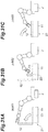
- FIG. 31A, 31B, and 31C schematically illustrate an execution flow including three work jobs for operating the robot 2 in an environment including the box 11 having the lid 12 and accommodating the bolt 13, for example.
- FIG. 31A shows an operation job "Job01" for opening the lid 12.
- FIG. 31B shows another work job “Job02” for taking out the bolt 13 from the box 11.
- FIG. 31C shows still another job "Job03" for closing the lid 12 of the box 11.
- the operation pattern defined by each of Jobs 01, 02, 03 includes an operation of physically manipulating a work object.
- the operation pattern defined by Job01 includes an operation of using the lid 12 as a work object to change the lid 12 from a closed state to an open state.
- the operation pattern defined by Job02 includes an operation of taking out the bolt 13 from the box 11.
- the operation pattern defined by Job03 includes an operation of closing the lid 12 from the open state to the closed state.
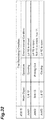
- each environmental condition includes a condition that specifies the state of an object included in the work environment of the robot.
- An object included in the work environment of the robot may include the above-described work object and other objects.
- the operation of opening the lid 12 of Job01 cannot be executed unless the lid 12 is closed.
- the lid 12 is closed is set as an environmental condition for designating the state of the lid 12 that is the work object of the job.
- the operation of taking out the bolt 13 from the box 11 of Job02 cannot be executed unless the bolt 13 is located in the box 11 and the lid 12 is open.
- the programming support apparatus 100 may be configured to identify the environmental state of a subsequent work job (hereinafter referred to as "second work job") based on at least the work content of the robot in a preceding work job (hereinafter referred to as "first work job"); and determine whether the environmental condition satisfies the environmental condition of the second work job.
- second work job the environmental state of a subsequent work job
- first work job the work content of the robot in a preceding work job
- the planning support apparatus 100 may be configured to: identify a state of the work object after the robot 2 operates in accordance with the first work job as an environmental state at the time of executing the second work job; and determine whether the environmental state satisfies the environmental condition of the second work job.
- the environmental state means a state that actually occurs in the work environment of the robot 2 at each timing in the execution flow when the robot 2 operates in accordance with the execution flow. Similar to the environmental condition, the environmental state includes a state of an object included in the work environment of the robot 2.
- the object included in the work environment of the robot 2 may include the above-described work object and other objects.
- the programming support apparatus 100 identifies "open", which is the state of the lid 12 after the robot operates according to Job01, as the environmental state at the execution timing of Job02. Further, since Job01 does not include an operation for the bolt 13, the programming support apparatus 100 does not change the state of the bolt 13 before and after the robot 2 operates according to Job01, and continues to keep the state of the bolt 13 in Job02 "In box 11". The programming support apparatus 100 determines whether or not these environmental state satisfy the environmental condition of Job02. Since the environmental conditions in Job02 include "the bolt 13 is in the box 11" and "the lid 12 is open", the environmental state satisfies the environmental condition in Job02.
- the planning support apparatus 100 may be configured to: identify the environmental state in the time of executing the second work job based on at least the work content of the robot in the first work job; update the environmental state based on at least the work content of the robot in the second work job so as to identify the environmental state of the third work job; and determine whether the environmental state satisfies the environmental condition of the third work job.
- the programming support apparatus 100 identifies the state of the lid 12 and the bolt 13 at the execution timing of Job02 to "open” and "in the box 11" based on the operation content of the robot in Job01. Furthermore, the programming support apparatus 100 identifies "outside the box 11", which is the state of the bolt 13 after the robot has operated in accordance with Job02, as the environmental state at the execution timing of Job03. Further, since Job02 does not include an operation on the lid 12, the programming support apparatus 100 does not change the state of the lid 12 before and after the robot 2 operates in accordance with Job02, and continues to keep the state of the lid 12 in Job03 "open". The programming support apparatus 100 determines whether these environmental conditions satisfy the environmental condition of Job03. Since the environmental condition in Job03 includes "the lid 12 is open” and does not include the condition for the bolt 13, the environmental state satisfies the environmental condition in Job03.
- the planning support apparatus 100 may be configured to: generate, based on an environmental condition of the one work job in the execution flow and the operation content of the robot 2 in the other work job in the execution flow, an order condition required between the one work job and the other work job so that the one work job satisfies the environment; and determine whether the execution order of the execution flow satisfies the execution order.
- the execution flow generates an order condition that Job02 is executed after Job01 and before Job03 based on the "Open” which is the state of the lid 12 after the robot 2 is operated in accordance with Job01, "Closed”, which is the state of the lid 12 after the robot 2 is operated in accordance with Job03, and "the lid 12 is open", which is specified by the environmental condition of Job02.
- the execution order of the execution flow in FIG. 31 satisfies the order condition.
- the programming support apparatus 100 may be further configured to set a timing condition identifying a relationship of an execution timing between at least two of the work jobs to be executed in accordance with an input to the user interface.
- timing condition include conditions for specifying the order of work jobs, as well as conditions for specifying a waiting time to be secured between the work jobs.
- programming support apparatus 100 may determine whether the at least one work job satisfies the environmental condition in the execution flow in which the execution order is defined so that the timing condition is satisfied.
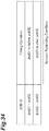
- FIG. 34 shows an example of setting timing conditions.
- a condition that "Job01 is executed before Job02" is set between Job01 and Job02
- a condition that "Job03 is executed after Job02" is set between Job02 and Job03.
- the state of the lid 12 at the execution timing of Job02 is necessarily "open". Therefore, when the timing condition shown in FIG. 34 is set, it is not essential to specify the state of the lid 12 as the environmental condition of Job02. In other words, if the environmental condition of Job02 includes "the lid is open", it is not essential to set the timing condition of FIG. 34 .
- the operation program (that is supported by the programming support apparatus 100) is executed by a controller for example, that controls one or more control target(s) such as robot 2.
- the control target(s) is not limited to one robot 2.
- the programming support apparatus 100 may be configured to execute programming support of an operation program for controlling a plurality of control targets (for example, a plurality of robots 2).
- the programming support apparatus 100 includes: a main body 110 comprising one or more computers; and a user interface 130.
- the user interface 130 includes a monitor 131 and an input device 132, for example.
- the monitor 131 is an apparatus used for displaying information output from the main body 110.
- the monitor 131 may be of any type as long as graphic display is possible on the monitor, and a specific example thereof is a liquid crystal panel.
- the input device 132 is an apparatus used for inputting information into the main body 110.
- the input device 132 may be of any type as long as desired information can be input on the apparatus, and specific examples thereof include a keypad and a mouse. Note that the monitor 131 and the input device 132 may be integrated as a touchscreen having both an input function and a display function.
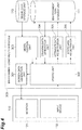
- the main body 110 includes a main module 200, an environment construction module 300, a condition setting module 400, a programming module 500, and a simulation module 600, as a functional configuration (hereinafter referred to as "functional module").
- the main module 200 is a module for invoking various functions of the programming support apparatus 100 in accordance with user's input.
- the environment construction module 300 is a module for constructing environment model data (model data) for operation simulation of the robot 2.
- the environment model data is, for example, three-dimensional surface data including models of the robot 2 and of its surrounding environment constituted by polygons.
- the environment construction module 300 writes the constructed environment model data into an environment data storage 111.
- the condition setting module 400 is configured to set a programming support condition including the first restricting condition which is a restricting condition for execution for each work job and the second restricting condition which is a restricting condition regarding the relationship between work jobs.
- the first restricting condition includes a condition that is unavoidable to achieve the purpose of the work job, such as the environmental condition described above.
- a condition that is unavoidable to achieve the purpose of the work job such as the environmental condition described above.
- the above-mentioned unavoidable condition is that the work job is executed with a lid open.
- the above-mentioned unavoidable conditions are that the tool is held, the tool is turned on, and the like.
- the second restricting condition includes a condition that defines the relationship between work jobs, such as the timing condition described above.
- the relationship between work jobs may be derived from the first restricting condition, or may not be derived from the first restricting condition.
- the second restricting condition includes a condition that is not unavoidable in order to achieve the purpose of each work job.
- the programming module 500 is a module configured to execute programming support of the operation program in accordance with the programming support condition set by the condition setting module 400. For example, the programming module 500 generates an operation program in accordance with the above-described programming support condition and writes the generated operation program into an operation program storage 112. the programming module 500 may check a provisional execution flow in order to generate the operation program.
- the simulation module 600 is a module to execute operation simulation of the robot 2.
- the operation simulation represents causing the model of the robot 2 to operate under a simulation environment.
- the simulation module 600 causes the model of the robot 2 to operate in accordance with the above-described operation program (operation program stored in the operation program storage 112) under the simulation environment specified by the above-described environment model data (environment model data stored in the environment data storage 111).
- the main module 200 includes a window data generation unit 201 and a module switching unit 202.
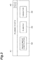
- the window data generation unit 201 generates data for displaying a main window A1 (see FIG. 3 ) on the monitor 131.
- the main window A1 is an operation window for invoking various functions of the programming support apparatus 100.
- the module switching unit 202 is associated with one or more buttons on the user interface for switching modules to be executed in response to an operation input in the main window A1.
- the main window A1 includes an environment construction button A2, a planning button A3, a simulation button A4, and a finish button A5.
- the environment construction button A2 is a button for activating the environment construction module 300.
- the planning button A3 is a button for activating the condition setting module 400 and the programming module 500.
- the simulation button A4 is a button for activating the simulation module 600.
- the finish button A5 is a button for closing the main window and finishing the processing by the main module 200.
- the environment construction module 300 includes, as subdivided functional modules, a window data generation unit 301, an update unit 302, a model addition unit 303, a drawing data generation unit 304, an attribute data registration unit 305, and a state data registration unit 306.
- the window data generation unit 301 generates data for displaying an environment construction window B1 on the monitor 131.
- the environment construction window B1 is an input window for environment model data construction.
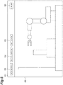
- the environment construction window B1 allows: adding a model (via a model addition button B3) to the simulation environment (represented at a simulation environment area B2); defining attributes of the model (via an attribute setting button B4); and setting a state of the model (via a state setting button B5).
- a model represents an object in a simulation environment.
- the model is also referred to herein as "input target model.”
- the model represents an object in the simulation environment.
- the input target model may be selected from the image displayed in the simulation environment area (B2). As illustrated in FIG.
- the environment construction window B1 includes the simulation environment area B2, the model addition button B3, the attribute setting button B4, the state setting button B5, and a finish button B6, for example.
- the simulation environment area B2 is an area for displaying a simulation environment indicated by the environment model data under construction, with a three-dimensional image, or the like.
- the model addition button B3 is a button for adding model data to the environment model data.
- the model data is three-dimensional surface data constituted with polygons, for example.
- the attribute setting button B4 is a button for inputting data (hereinafter referred to as "attribute data”) specifying an object (i.e. the "input target model”) included in environment model data.
- the state setting button B5 is a button for inputting data (hereinafter referred to as "state data") indicating a state of an object included in the environment model data.
- state data data indicating a state of an object included in the environment model data.
- Specific examples of the state data in a case where the object is a lidded box include “a state where the lid is open” and “a state where the lid is closed”. Another example is “on state”, “off state”, and the like, in a case where the object is a tool turned on/off in use.
- the finish button B6 is a button for closing the environment construction window B1 and finishing the processing of the environment construction module 300.
- the update unit 302 updates display data for the environment construction window B1 in accordance with an operation input to the input device 132. For example, the update unit 302 updates the display data for the environment construction window B1 so as to display a model selection window C1 in response to the clicking on the model addition button B3. In response to the clicking on the attribute setting button B4, the update unit 302 updates the display data for the environment construction window B1 so as to display an attribute input window D1. Furthermore, the update unit 302 updates the display data for the environment construction window B1 so as to display a state input window F1 in response to the clicking on the state setting button B5.
- the model selection window C1 is a window for selecting model data to be added to the environment model data.
- the model selection window C1 includes a list display area C2 and an add button C3.
- the list display area C2 displays a list of model data that can be added to the environment model data.
- the add button C3 is a button for instructing addition of model data selected in the list display area C2.
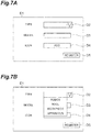
- the attribute input window D1 shown in FIGS. 7A and 7B is opened on the user interface.
- the attribute input window D1 is for inputting attribute data of an input target model.
- the input target model can be selected by clicking on any of the models displayed in the simulation environment area B2 ( FIG. 5 ), as a component of the environment data.
- the attribute input window D1 includes an input box D2, an input box D3, an icon addition button D4, and a registration button D5.
- the input box D2 is an input box for inputting an input target model type (for example, "Robot”, “Tool”, “Workpiece”, “Apparatus”, etc.).
- the input box D2 may be configured to enable selection input by pre-registered options (refer to FIG. 7B ).
- the input box D3 is an input box for inputting a name of the above-described input target model.
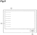
- the icon addition button D4 is a button for inputting icon data to be associated with the input target model. For example, the icon data can be input on an icon selection window E1 ( FIG. 8 ) displayed by clicking on the icon addition button D4.
- the icon selection window E1 includes a list display area E2 and an add button E3.
- the list display area E2 displays a list of available icon data.
- the add button E3 is a button for instructing addition of the icon data selected in the list display area E2.
- the registration button D5 is a button for instructing registration of data input in the attribute input window D1.
- the registration button D5 is a button for registering (or recording) in a storage the attribute data that has been entered, in association with the input target model (or "object”, or "model component” of the simulation environment).
- the state input window F1 shown in FIG. 9 is opened on the user interface.
- the state input window F1 includes an input box F2, an input box F3, and a registration button F4.
- the input box F2 is an input box for selecting an input target model.
- the input box F2 may be configured so as to enable selection input of a model name registered in the environment data storage 111.
- the input box F3 is an input box for inputting the name of the state.
- the registration button F4 is a button for registering (or recording) in a storage the state that has been entered, in association with the input target model (or "object", or "model component” of the simulation environment) having been selected in the state input window F1.
- the update unit 302 updates the display data for the simulation environment area B2 to display an image in the simulation environment after model data has been added to the environment model data, via the model addition button B3 in the environment construction window B1 ( FIG. 5 ).
- the model addition unit 303 adds model data to the environment model data in the environment data storage 111 in accordance with an input via the user interface 130. For example, in response to the clicking on the model addition button B3 ( FIG. 5 ), the model addition unit 303 generates a list of model data with reference to the model data storage 113 and outputs the list to the update unit 302 as display data for the list display area C2 ( FIG. 6 ).
- the model data storage 113 stores a plurality of pieces (or data components) of model data that may be created beforehand.
- the model data storage 113 may be provided in the programming support apparatus 100 or may be provided in another apparatus (for example, a computer for three-dimensional design) other than the programming support apparatus 100.
- the model addition unit 303 retrieves the model data selected (via the add button C3) from the model data storage 113, and adds the model data to the environment model data in the environment data storage 111.
- the drawing data generation unit 304 generates drawing data for the simulation environment using the environment model data stored in the environment data storage 111 and outputs the drawing data to the update unit 302 as display data for the simulation environment area B2 ( FIG. 5 ).
- the attribute data registration unit 305 adds the above-described attribute data to the environment data in the environment model data storage 111. For example, the attribute data registration unit 305 obtains the data input on the attribute input window D1 ( FIGS. 7A and 7B ) in response to the clicking on the registration button D5 ( FIGS. 7A and 7B ), and writes the data into the environment data storage 111 in association with the input target model.
- the state data registration unit 306 adds the above-described state data to the environment data of the environment model data storage 111. For example, the state data registration unit 306 obtains the data input on the state input window F1 ( FIG. 9 ) in response to the clicking on the registration button F4 ( FIG. 9 ), and writes the data into the environment data storage 111 in association with the input target model.
- the condition setting module 400 ( FIG. 2 ) separately sets the first restricting condition and the second restricting condition.
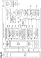
- the condition setting module 400 includes, as subdivided functional modules, a window data generation unit 401, a first update unit 402, a second update unit 403, a third update unit 404, a list generation unit 405, a restriction menu generation unit 406, a first input support unit 408, a second input support unit 409, an option information acquisition unit 410, a condition reading unit 411, a first condition setting unit 412, a provisional flow generation unit 416, a second condition setting unit 417, a computation level setting unit 418, and a condition registration unit 419.
- the window data generation unit 401 generates display data for an input window (see FIG. 11 ) including a first input area for inputting the first restricting condition and a second input area for inputting the second restricting condition and outputs the generated data to the monitor 131.
- the window data generation unit 401 may generate display data for an input window further including a list display area indicating a list of a plurality of work jobs.
- the window data generation unit 401 may generate the display data for the input window so as to allow the list display area to be arranged between the first input area and the second input area.
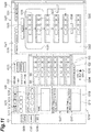
- the window data generation unit 401 generates display data for a planning window G1 (input window) illustrated in FIG. 11 .
- the planning window G1 includes a list display area G2, a first input area G9, a second input area G20, a restriction menu display area G32, a third input area G34, a condition registration button G36, a planning button G37, and a save button G38.
- the list display area G2 displays a list containing list elements G3 corresponding to a plurality of work jobs created beforehand.
- the list element G3 may be sequenced according to a given chronological order.
- the list element G3 includes a name display section G5 and an icon display section G6.
- the name display section G5 displays names of work jobs in text format.
- the icon display section G6 displays one or more icons related to the content of a work job (for example, an icon of a work object).
- the first input area G9 is an area for inputting the first restricting condition.
- the first input area G9 includes a work content input area G10 and a restricting condition input area G16.
- the work content input area G10 is an area for inputting information specifying the content of the work job (hereinafter referred to as "work content information").
- the work content information includes information specifying the work object and information specifying the operation content to be applied on the work object, for example. Note that any work object may be employed as long as it is a target of work by the robot 2.
- the work object also includes a tool used by the robot 2 in the working on the workpiece because the tool is one of targets of conveyance work by the robot 2.
- the work content input area G10 includes a plurality of item designation buttons G11, an icon selection area G12, an input content display area G13, and a name input area G15.
- the item designation button G11 is a button for selecting an item of the above-described work content information.
- the icon selection area G12 displays options that can be input in the item selected by clicking on the item designation button G11, as icons. For example, when the "TARGET" button (among the buttons G11) is clicked, options of targets (for example, a box, a bolt, an object that is contained in the box, etc.) are displayed as icons.
- buttons G11 when the "TOOL" button (among the buttons G11) is clicked, options of tools (for example, a screw driver, a wrench, a jig, etc.) are displayed as icons.
- the input content display area G13 displays the work content information that has been input.
- the name input area G15 obtains an input for the name of the work job.
- the restricting condition input area G16 is an area for inputting restricting conditions.
- the restricting condition input area G16 includes a plurality of condition input sections G17. Each of the condition input sections G17 obtains an input of one restricting condition.
- the condition input section G17 includes a new creation button G18 and a display section G19.
- the new creation button G18 is a button for displaying a condition creation window H1 (described below, with reference to FIGS. 12A and 12B ).
- the display section G19 displays the conditions created via the condition creation window HI.
- the second input area G20 is an area for inputting the second restricting condition.
- the second input area G20 includes a condition input section G21 and a result output section G29.
- the condition input section G21 includes a flow display section G22 and a tab G28.
- the flow display section G22 displays a provisional flow G23 in which a plurality of flow elements G24 is arranged, and displays at least one condition element G25.
- the provisional flow G23 represents a procedure containing the work jobs to be executed by the control target (e.g. the robot 2).
- the provisional flow G23 illustrates execution order of a plurality of work jobs selected for constituting the operation program.
- Each of the plurality of flow elements G24 corresponds to each of the plurality of work jobs.
- the second input area G20 may display a plurality of the provisional flows G23 each corresponding to each of the plurality of control targets, as illustrated in FIG. 11 by the tabs entitled "Procedure 1" and "Procedure 2".
- the condition element G25 illustrates a second restricting condition set between work jobs in the provisional flow G23.
- the condition element G25 is displayed in association with two flow elements G24 corresponding to two work jobs as setting targets of the second restricting condition.
- condition element G25 indicates a restricting condition of grouping the first work job and the second work job as one set of jobs and is displayed as a frame to surround the first flow element G24 and the second flow element G24.
- the condition element G26 indicates a restricting condition defining a time interval to be ensured between a fifth work job and a sixth work job, and is illustrated on a line connecting the fifth flow element G24 and the sixth flow element G24.
- the condition element G27 indicates a restricting condition defining a time interval to be ensured between a third work job and the fifth work job, and is illustrated on a line connecting the third flow element G24 and the fifth flow element G24 without passing through the fourth flow element G24.
- the tab G28 is provided at an upper portion of the flow display section G22 and is used for switching display between the condition input section G21 and the result output section G29.
- the result output section G29 displays an execution flow generated by the programming module 500.
- the result output section G29 includes a flow display section G30 displaying an execution flow, and a tab G31.
- the flow display section G30 is displayed at a same position as the flow display section G22.
- the tab G31 is provided at the upper portion of the flow display section G30 at a position different from the tab G28 described above. Clicking on the tab G31 in a state where the flow display section G22 is displayed enables the flow display section G30 to be displayed. Clicking on the tab G28 in a state where the flow display section G30 is displayed enables the flow display section G22 to be displayed.
- the restriction menu display area G32 displays a list of a plurality of restricting conditions that can be input in the second input area G20.
- the restriction menu display area G32 displays in order a plurality of menu elements G33 each corresponding to each of the plurality of restricting conditions.
- the restriction menu display area G32 is arranged adjacent to the list display area G2, between the first input area G9 and the second input area G20.
- the third input area G34 obtains an input of a computation level (described below) in the programming support.
- the third input area G34 is configured to enable selection of a plurality of preset computation levels by radio buttons G35.
- the third input area G34 is arranged between the first input area G9 and the second input area G20, and is arranged so as to be adjacent to the list display area G2 on the side opposite to the restriction menu display area G32.
- the condition registration button G36 is a button for instructing registration of input content to the first input area G9, the second input area G20, and the third input area G34.
- the planning button G37 is a button for instructing the execution of programming support according to the input content that has been entered into the first input area G9, the second input area G20, and the third input area G34. Executing the programming support may be, for example, generating an operation program for operating a robot controller.
- the save button G38 is a button to instruct to save the operation program generated by the programming support.
- the configuration of the planning window G1 is merely an example.
- the input window may be configured in any manner as long as it includes the first input area and the second input area.
- the input window may be configured such that the first input area and the second input area are positioned above and below the list display area, respectively.
- the input window may be configured to switch at least a portion of the first input area and at least a portion of the second input area to be displayed at a same position.
- the first update unit 402 updates the display data for the first input area G9 in accordance with an input to the user interface 130.
- the first update unit 402 may update the display data for the first input area G9 so as to enable the first restricting condition of the work job selected in the list display area G2 to be input. For example, when any of the list elements G3 is clicked (and thereby selected) in the list display area G2, the first update unit 402 updates display data for the first input area G9 to enable an input of the first restricting condition of the work job corresponding to the selected list element G3.
- the first update unit 402 updates the display data for the first input area G9 so as to display information at an input portion of an item having information already registered for the work job, and so as to leave the input portion of other item blank.
- a work job may already have one or more condition set for some items (target, tool, etc.).
- the first update unit 402 obtains the already registered information from the condition reading unit 411 described below.
- the first update unit 402 updates the display data for the first input area G9 in accordance with the input to the first input area G9. For example, when the work content information has been input by the operation on the item designation button G11 and the icon selection area G12, the first update unit 402 updates the input content display area G13 so as to reflect the input content.
- the first update unit 402 displays the input content in the name input area G15 in accordance with the text input to the name input area G15.
- the first update unit 402 updates the display data for the first input area G9 so as to display the condition creation window H1 in response to the clicking on the new creation button G18 in the condition input section G17.
- the condition creation window H1 includes an input box H2, an input box H3, an input box H4, and a creation button H5.
- the input box H2 is an input box for inputting a work object.
- the input box H3 is an input box for inputting an application timing of the restricting condition.
- the application timing is information indicating at which time point the restricting condition is to be applied during the execution of the work job.
- the input box H4 is an input box for inputting a state designation condition for designating a state of the work object as one example of the restricting condition.
- the input boxes H2, H3, and H4 may be configured to enable selection input of pre-registered options (refer to FIG. 12B ).
- the creation button H5 is a button for instructing creation of a condition according to the data input in the condition creation window H1.
- the first update unit 402 creates a condition according to the data input in the condition creation window H1, and displays the display data for the first input area G9 so as to display the condition in the display section G19.
- the second update unit 403 updates the display data for the second input area G20 in accordance with the input to the user interface 130.
- the second update unit 403 updates the display data for the second input area G20 so as to display a plurality of selected work jobs in the list display area G2 and to enable an input of the second restricting condition between the plurality of selected work jobs.
- the second update unit 403 may update the display data for the second input area G20 so as to display the provisional flow G23 of the plurality of selected work jobs in the list display area G2 and to enable the input of the second restricting condition between a plurality of selected work jobs in the provisional flow G23. For example, every time an input of arranging the list element G3 selected in the list display area G2 in the second input area G20 is performed, the second update unit 403 updates the display data so as to add the work job corresponding to the list element G3 to the display of the second input area G20. More specifically, the second update unit 403 updates the display data so as to add the flow element G24 corresponding to the work job in the provisional flow G23.
- Specific examples of the input to arrange a list element G3 selected in the list display area G2 in the second input area G20 include a drag input of the list element G3 from the list display area G2 to the second input area G20 and an input by pasting the list element G3 copied from the list display area G2 into the second input area G20, although the input method is not limited to these.
- the second update unit 403 may update the display data for the second input area G20 so as to display each of the plurality of provisional flows G23 corresponding to each of the plurality of control targets.
- the second update unit 403 updates display data for the second input area G20 so as to insert the restricting condition corresponding to the menu element G33 between the flow elements G24.
- an input to arrange the menu element G33 selected from the restriction menu display area G32, into the second input area G20 include a drag input of the menu element G33 from the restriction menu display area G32 to the second input area G20 and an input by pasting the menu element G33 copied at the restriction menu display area G32 to the second input area G20, although the input method is not limited to these.
- the second update unit 403 may update the display data for the second input area G20 so as to insert a restricting condition between the flow elements G24 of mutually different control targets.
- a second restricting condition may be inserted or added, by first selecting two of the flow elements, for example.
- the selection may include clicking on (or selecting) a line connecting the two flow elements G24.
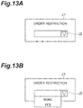
- the second update unit 403 updates the display data for the second input area G20 so as to display a regulation input window J1 (see FIGS. 13A and 13B ).
- the regulation input window J1 is for inputting restricting conditions between the work jobs corresponding to the selected flow elements G24.
- the regulation input window J1 includes an input box J2.
- the input box J2 is for inputting a presence or absence of an order restriction (prohibition of order change).
- the input box J2 may be configured to enable selective input of "YES" (to indicate the presence of an order restriction) and "NONE" (to indicate the absence of an order restriction) (refer to FIG. 13B ).
- the provisional flow G23 is generated by the provisional flow generation unit 416.
- the provisional flow generation unit 416 sets the order of the first work job and the second work job based on the positional relationship between the drag completion position and the existing flow element G24 to generate the first provisional flow G23.
- the provisional flow G23 includes a first flow element G24 corresponding to a first work job, and a list element G3 corresponding to a second work job is drag-and-dropped below the first flow element G24, in the second input area G20, then a second flow element G24 is created, and the provisional flow G23 is updated to reflect that the second work job is to be executed after the first work job.
- the provisional flow G23 is updated to reflect that the second work job is to be executed before the first work job.
- the provisional flow generation unit 416 inserts into the provisional flow G23, a work job corresponding to the list element G3. Accordingly, the provisional flow generation unit 416 receives an insertion position of the work job in accordance with the relationship between the existing flow element G24 and the drag completion position.
- the provisional flow generation unit 416 may generate each of a plurality of provisional flows G23 corresponding to each of the plurality of control targets.
- the third update unit 404 updates the display data for the third input area G34 in accordance with the input to the user interface 130. For example, the third update unit 404 updates the display data so as to turn on the radio button G35 that is clicked or selected in the third input area G34.
- the list generation unit 405 generates a list of work jobs, to be displayed in the list display area G2, and outputs the list to the window data generation unit 401. For example, the list generation unit 405 generates the list of work jobs with reference to the work job storage 114.
- the work job storage 114 stores a plurality of work jobs created beforehand by a user.
- the work job storage 114 may be provided in the programming support apparatus 100 or may be provided in an apparatus other than the programming support apparatus 100 (for example, the robot controller 3).
- the restriction menu generation unit 406 generates a list of restricting conditions to be displayed in the restriction menu display area G32, and outputs the list to the window data generation unit 401. For example, the restriction menu generation unit 406 generates the list of restriction menus with reference to the restriction menu storage 407.
- the restriction menu storage 407 stores a plurality of restriction menus created beforehand.
- the option information acquisition unit 410 obtains first option information specifying an object contained in the environment model data and second option information indicating the state of the object from the above-described environment data storage 111.
- the first input support unit 408 sets options of work objects and generates option display data. For example, the first input support unit 408 generates options for allowing selection input of work objects to the input box H2 ( FIGS. 12A and 12B ), on the condition creation window HI.
- the first input support unit 408 may set the options of the work object based on the first option information. In this case, the information obtained by the environment construction module 300 is used as options of the work object.
- the second input support unit 409 sets options for the state designation condition in accordance with the work object as a state designation target, and generates option display data. For example, the second input support unit 409 generates options for allowing selection input of a state to the input box H4 ( FIGS. 12A and 12B ) in accordance with the work object input in the input box H2, in the condition creation window H1.
- the second input support unit 409 may set the options of the state designation condition based on the second option information. In this case, the information obtained by the environment construction module 300 is used as options of the state designation condition.
- the second input support unit 409 extracts the state of the work object input to the input box H2, from the second option information, and sets the extraction result as options of the state designation condition.
- the first condition setting unit 412 sets the first restricting condition in accordance with the input to the user interface 130 and writes the first restricting condition into a condition buffer 415 as a temporary storage in association with identification information of the work job as a target of the first restricting condition.
- the first restricting condition may include a state designation condition to designate the state of the work object of the work job.
- the first condition setting unit 412 may include an object setting unit 413 and a state setting unit 414 as subdivided functional modules.
- the object setting unit 413 sets the work object of the work job based on an input in the first input area G9. For example, the object setting unit 413 sets the work object of the work job based on the content displayed in the input content display area G13.
- the state setting unit 414 sets the state designation condition based on an input to the first input area G9. For example, the state setting unit 414 sets the state designation condition of the work object based on the content input to the condition input section G17.
- the second condition setting unit 417 sets the second restricting condition being a restricting condition on a relationship between the work jobs in accordance with the input to the user interface 130. For example, the second condition setting unit 417 sets the second restricting condition based on the restricting condition input between the work jobs in the second input area G20.
- the second condition setting unit 417 may set a restricting condition between the work jobs of mutually different control targets.
- the computation level setting unit 418 sets a computation level (described below) in the programming support in accordance with the input to the user interface 130. For example, the computation level setting unit 418 sets the computation level for adjusting a criterion for determining adoptability of an execution flow described below.
- the condition registration unit 419 registers at least one of the first restricting condition and the second restricting condition in a condition storage.
- the condition registration unit 419 may write the storage content of the condition buffer 415 (e.g. associated with the first restricting condition) into an individual condition storage 420.
- the condition registration unit 419 writes the second restricting condition set by the second condition setting unit 417 into an inter-job condition storage 422 in association with the work job as a target of the second restricting condition.
- the condition registration unit 419 writes a plurality of work jobs displayed in the second input area G20 into an execution target storage 421 as execution target jobs.
- condition registration unit 419 writes each of a plurality of work jobs corresponding to each of the plurality of flow elements G24 of the provisional flow G23 into the execution target storage 421 as execution target jobs. Furthermore, the condition registration unit 419 writes the computation level set by the computation level setting unit 418 into a computation condition storage 423.
- the condition reading unit 411 reads at least one of the first restricting condition and the second restricting condition from the condition storage. For example, the condition reading unit 411 reads the first restricting condition from the individual condition storage 420.
- the programming module 500 is activated in response to clicking on the planning button G37 ( FIG. 11 ). As illustrated in FIG. 14 , the programming module 500 includes a planning support unit 501 and a program generation unit 510, as subdivided functional modules.
- the planning support unit 501 checks the execution timing of at least one of the work jobs based on the first restricting condition and the second restricting condition.
- the check means confirming whether the first restricting condition and the second restricting condition are satisfied.
- the planning support unit 501 performs: storing a plurality of work jobs defining an operation pattern of the robot 2; setting, in accordance with an input to a user interface, an environmental condition that specifies an operation environment of the robot 2 for one of the work jobs in accordance with an input to a user interface; setting a plurality of work jobs to be executed by the robot in the plurality of work jobs in accordance with an input to the user interface; and determining, in an execution flow for defining an execution order of the plurality of work jobs set by the second condition setting unit, whether at least one of the work jobs satisfies the environmental condition based on the execution order.
- the execution flow may be automatically generated by the planning support unit 501 or may be set and input by the user. Below, the case where the planning assistance part 501 generates an
- the planning support unit 501 includes, as subdivided functional modules, a checking unit 504, a flow adjustment unit 503, a path information acquisition unit 505, a transitional job generation unit 506, a flow evaluation unit 507, and an update unit 502.
- the checking unit 504 checks an execution timing of at least one of the work jobs based on the first restricting condition stored in the individual condition storage 420 and the second restricting condition stored in the inter-job condition storage 422. The checking unit 504 determines, based on the execution order, whether or not at least one work job satisfies the environmental condition in the execution flow in which the execution order of the plurality of execution target work jobs is determined.
- the checking unit 504 is configured to identify an environmental state at the time of executing one of the work jobs in the execution flow based on the operational content of the robot 2 in another work job in the execution flow and the execution order of the execution flow; and determine whether the environmental state satisfies the environmental condition of the one of the work jobs.
- the checking unit 504 is configured to: identify the environmental state in the time of executing the second work job based on at least the work content of the robot 2 in the first work job; and determine whether the environmental state satisfies the environmental condition of the second work job.
- the checking unit 504 may identify the state of the work object after the robot 2 operates in accordance with the first work job as the environmental state at the execution timing of the second work job, and check whether the environmental state satisfies the environmental condition of the second work job.
- the checking unit 504 may be configured to: identify the environmental state in the time of executing the second work job based on at least the work content of the robot in the first work job; update the environmental state based on at least the work content of the robot in the second work job so as to identify the environmental state of the third work job; and determine whether the environmental state satisfies the environmental condition of the third work job.
- the checking unit 504 may be configured to: generate, based on an environmental condition of the one work job in the execution flow and the operation content of the robot in the other work job in the execution flow, an order condition required between the one work job and the other work job so that the one work job satisfies the environmental condition; and determine whether the execution order of the execution flow satisfies the execution order.
- the flow adjustment unit 503 generates an execution flow to be determined by the checking unit 504 so as to satisfy the timing condition. Further, when it is determined that any work job does not satisfy the environmental condition in the execution flow, the execution order is changed so as to satisfy the timing condition. For example, the flow adjustment unit 503 randomly generates an execution flow of the plurality of work jobs stored in the execution target storage 421 in a range where the timing condition is satisfied. After that, when it is determined that any work job does not satisfy the environmental condition in the execution flow, the flow adjustment unit 503 randomly changes the execution order so as to satisfy the timing condition. Thereafter, the flow adjusting unit 503 repeats changing the execution order until the execution flow that satisfies the timing condition does not include a work job that does not satisfy the environmental condition. Every time an execution flow is generated or changed, the flow adjustment unit 503 overwrites the result in a flow buffer 508 as a temporary storage.
- the flow adjustment unit 503 may generate a plurality of execution flows each respectively corresponding to each of the plurality of control targets.
- the path information acquisition unit 505 obtains first path information that defines an operation path of the robot 2 (temporal transition of the position and attitude of the distal end portion 2a) for at least one of the work jobs. For example, the path information acquisition unit 505 reads all the first path information of the work job as an execution target from the execution target storage 421.
- the transitional job generation unit 506 generates second path information defining the operation path of the robot 2 between the work jobs based on the execution flow stored in the flow buffer 508, the first path information obtained by the path information acquisition unit 505, and the environment model data stored in the environment data storage 111. For example, the transitional job generation unit 506 connects between an end point of an operation path of a preceding work job and a start point of an operation path of a subsequent work job to generate the second path information so as to avoid collision between the robot 2 and its surrounding objects, and writes the second path information into a path buffer 509 as a temporary storage.
- the transitional job generation unit 506 repeats generation of a via point capable of avoiding a collision and correction of the path so as to pass through the via point until collision avoidance is achieved over the entire path.
- a more specific method of generating the path is disclosed in, for example, Japanese Patent No. 4103057 .
- the flow evaluation unit 507 evaluates the execution flow and the first path information and/or the second path information based on an evaluation condition different from the first restricting condition and the second restricting condition, and determines adoptability of the execution flow based on an evaluation result. For example, the flow evaluation unit 507 evaluates the execution flow, the first path information, and the second path information based on the evaluation condition, and determines adoptability of the execution flow based on the above-described evaluation result.
- the evaluation result may give an indication of the execution time if the execution flow was executed as an operation program, the energy consumption of executing the operation program, and/or the like. The evaluation result may be compared with a reference value in order to determine whether the evaluation condition is satisfied, and accordingly whether the execution flow is adoptable.
- the flow evaluation unit 507 derives a predetermined evaluation value for the operation program according to the execution flow, the first path information, and the second path information, and determines that the execution flow is adoptable in a case where the evaluation value has reached an acceptance level, and determines that execution flow is not adoptable in a case where the evaluation value has not reached the acceptance level.
- the evaluation value include an operation program execution time and power consumption of the operation program (power consumption of the robot 2 operating in accordance with the operation program).
- the evaluation value may be derived by combining the execution time and the power consumption.
- the flow evaluation unit 507 may repeat generation of the execution flow and derivation of the above-described evaluation value for a predetermined time, and may adopt an execution flow that achieves the most preferable evaluation value.
- the flow evaluation unit 507 may adopt an execution flow achieving the shortest operation program execution time or may adopt an execution flow achieving the lowest power consumption of the operation program.
- the flow evaluation unit 507 may adjust a criterion for determining adoptability of the execution flow according to the computation level stored in the computation condition storage 423. For example, the flow evaluation unit 507 may raise the above-described acceptance level or may extend the time for repeating the generation of the execution flow and the derivation of the above-described evaluation value in accordance with the raised computation level stored in the computation condition storage 423.
- the flow evaluation unit 507 may adjust accuracy of the operation program as an evaluation target in accordance with the computation level stored in the computation condition storage 423. For example, the flow evaluation unit 507 may reduce the operation time by simplifying the operation program as an evaluation target in accordance with the lowered computation level stored in the computation condition storage 423. Specific examples of simplification include omitting generation of the second path information so as to make the operation path between the work jobs linear, making the time between the work jobs constant, and roughening the mesh in the environment model data.
- the update unit 502 updates the display data for the second input area G20 so as to display the execution flow determined to be adoptable by the flow evaluation unit 507 in the result output section G29.
- the program generation unit 510 generates an operation program of the robot 2 based on the execution flow determined to be adoptable by the planning support unit 501.
- the operation program is obtained by arranging the above-described first path information and the second path information in accordance with the above-described execution flow.
- the program registration unit 511 registers the operation program generated by the program generation unit 510 in the operation program storage 112 in accordance with an input to the user interface 130. For example, in response to clicking on the save button G38, the program registration unit 511 writes the operation program into the operation program storage 112.
- the programming module 500 performs at least programming support based on the check result of the execution timing, and thus, the programming module 500 need not execute automatic generation of the operation program.
- the programming module 500 may be configured to display a warning in a case where the execution flow input by the user does not satisfy at least one of the first restricting condition and the second restricting condition.
- the simulation module 600 includes, as subdivided functional modules, a window data generation unit 601, an update unit 602, a program setting unit 603, a simulation execution unit 604, and a moving image data generation unit 605.
- the window data generation unit 601 generates data for displaying a simulation window K1 on the monitor 131.
- the simulation window K1 is a window for graphically displaying a simulation result.
- the simulation window K1 includes a drawing area K2, a program selection button K3, a simulation execution button K4, and a finish button K5.
- the drawing area K2 is an area in which a simulation result is displayed in a three-dimensional image or the like.
- the program selection button K3 is a button used to select an operation program as a simulation target.
- the simulation execution button K4 is a button for instructing execution of simulation.
- the finish button K5 is a button for closing the simulation window K1 and finishing the processing by the simulation module 600.
- the update unit 602 updates the display data for the simulation window K1 in accordance with an operation input to the input device 132. For example, the update unit 602 updates the display data for the simulation window K1 so as to display the program selection window L1 in response to the clicking on the above-described program selection button K3.
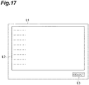
- the program selection window L1 is a window on which an operation program as a simulation target is selected.
- the program selection window L1 includes a list display area L2 and a selection button L3.
- the list display area L2 displays a list of selectable operation programs (for example, operation programs stored in the operation program storage 112).
- the selection button L3 is a button used to instruct selection of the operation program selected in the list display area L2.
- the update unit 602 updates display data for the drawing area K2 so as to display the moving image data in the list display area L2 after the simulation execution button K4 is clicked and moving image data (described below) corresponding to the simulation result is generated.
- the program setting unit 603 sets the operation program selected on the program selection window L1 to be an operation program as a simulation target.
- the simulation execution unit 604 executes operation simulation of the robot 2.
- the simulation execution unit 604 causes the model of the robot 2 to operate in accordance with the operation program as a simulation target under the simulation environment specified by the environment model data stored in the environment data storage 111.
- the moving image data generation unit 605 generates moving image data of the model of the robot 2 in accordance with a simulation result obtained by the simulation execution unit 604.
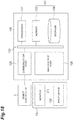
- FIG. 18 is a block diagram illustrating a hardware configuration of the main body 110.
- the main body 110 includes a circuit 120, and the circuit 120 includes one or more processors 121, a storage 122, a communication port 125, and an input/output port 126.
- the storage 122 includes a memory 123 and a storage 124.
- the storage 124 stores programs used to configure each of the above-described functional modules of the main body 110.
- the storage 124 may be of any type as long as it is a computer-readable storage. Specific examples include a hard disk, nonvolatile semiconductor memory, a magnetic disk, and an optical disk.
- the memory 123 temporarily stores the program loaded from the storage 124, calculation results of the processor 121, or the like.
- the processor 121 executes programs in cooperation with the memory 123, thereby constituting each of the functional modules.
- the communication port 125 inputs and outputs an electric signal to/from the robot controller 3 in accordance with a command from the processor 121.
- the input/output port 126 inputs and outputs an electric signal to/from the monitor 131 and the input device 132 in accordance with a command from the processor 121.
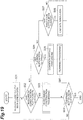
- step S01 the window data generation unit 201 generates display data for the main window A1 and outputs the data to the monitor 131.
- step S02 the module switching unit 202 confirms whether the environment construction button A2 has been clicked.
- step S03 the environment construction module 300 constructs environment model data for operation simulation of the robot 2. Specific processing content will be described below.
- step S04 the module switching unit 202 confirms whether the planning button A3 has been clicked.
- step S05 the condition setting module 400 executes processing of setting a programming support condition including the above-described first restricting condition and the above-described second restricting condition.
- step S06 the programming module 500 executes programming support of the operation program in accordance with the programming support condition set by the condition setting module 400. For example, the programming module 500 generates an operation program in accordance with the above-described programming support condition. Details of these specific processes will be described below.
- step S07 the module switching unit 202 confirms whether the simulation button A4 has been clicked.
- step S07 In a case where it is determined in step S07 that the simulation button A4 has been clicked, the programming support apparatus 100 executes step S08.
- step S08 operation simulation of the robot 2 is executed. Specific processing content will be described below.
- step S09 the module switching unit 202 confirms whether the finish button A5 has been clicked.
- step S09 the programming support apparatus 100 returns the processing to step S02. Thereafter, the processing corresponding to the clicking on the environment construction button A2, the planning button A3, or the simulation button A4 is repeated until the finish button A5 is clicked.
- step S09 the programming support apparatus 100 closes the main window A1 and finishes the processing.
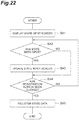
- step S11 the window data generation unit 301 generates display data for the environment construction window B1 and outputs the data to the monitor 131.
- step S12 the update unit 302 confirms whether the model addition button B3 has been clicked.
- step S13 the model addition unit 303 generates a list of model data with reference to the model data storage 113, and the update unit 302 generates display data for the model selection window C1 using the generated list, and updates display data for the environment construction window B1 so as to display the model selection window C1.
- step S14 the model addition unit 303 waits for selection input of model data on the model selection window C1.
- step S15 the model addition unit 303 obtains the model data selected on the model selection window C1 from the model data storage 113 and adds the obtained model data to the environment data of the environment model data storage 111.
- step S16 the drawing data generation unit 304 generates drawing data for the simulation environment using the environment model data stored in the environment data storage 111 and outputs the data to the update unit 302 as display data for the simulation environment area B2.
- step S17 the update unit 302 updates the display data for the simulation environment area B2 using the data output from the drawing data generation unit 304.
- step S18 the model addition unit 303 confirms whether at least one piece of model data has been added to the environment model data.
- step S19 the update unit 302 confirms whether the attribute setting button B4 has been clicked.
- step S19 the programming support apparatus 100 executes step S20.
- step S20 the attribute data registration unit 305 registers attribute data of the input target model. Specific processing content will be described below.
- step S19 the programming support apparatus 100 executes step S21.
- step S21 the model addition unit 303 confirms whether the state setting button B5 has been clicked.
- step S21 In a case where it is determined in step S21 that the state setting button B5 has been clicked, the programming support apparatus 100 executes step S22.
- step S22 the state data registration unit 306 registers the state data of the input target model. Specific processing content will be described below.
- step S23 the programming support apparatus 100 executes step S23.
- the update unit 302 confirms whether the finish button B6 has been clicked.
- step S23 In a case where it is determined in step S23 that the finish button B6 has not been clicked, the programming support apparatus 100 returns the processing to step S12. Thereafter, the construction processing of the environment model data is repeated until the finish button B6 is clicked.
- step S23 the programming support apparatus 100 closes the environment construction window B1 to finish the processing.
- step S31 the update unit 302 updates the display data for the environment construction window B1 so as to display the attribute input window D1.
- step S32 the update unit 302 determines whether information has been input to the attribute input window D1.
- step S33 the update unit 302 updates the display data for the attribute input window D1 so as to reflect the input content.
- step S34 the programming support apparatus 100 executes step S34.
- the programming support apparatus 100 executes step S34 without executing step S33.
- step S34 the update unit 302 confirms whether the registration button D5 has been clicked.
- step S34 the programming support apparatus 100 returns the processing to step S32. Thereafter, updating of the display data on the attribute input window D1 according to the input of the attribute data is repeated until the registration button D5 is clicked.
- step S35 the attribute data registration unit 305 obtains the data input on the attribute input window D1, and writes the data into the environment data storage 111 in association with the input target model. This completes the attribute data registration procedure.
- step S41 the update unit 302 updates the display data for the environment construction window B1 so as to display the state input window F1.
- step S42 the update unit 302 determines whether information has been input to the state input window F1.
- step S43 the update unit 302 updates the display data for the state input window F1 so as to reflect the input content.
- step S44 the programming support apparatus 100 executes step S44.
- the programming support apparatus 100 executes step S44 without executing step S43.
- the update unit 302 confirms whether the registration button F4 has been clicked.
- step S44 the programming support apparatus 100 returns the processing to step S42. Thereafter, updating of the display data on the state input window F1 according to the input of the state data is repeated until the registration button F4 is clicked.
- step S45 the state data registration unit 306 obtains the data input on the state input window F1, and writes the into the environment data storage 111 in association with the input target model. This completes the state data registration procedure.
- step S51 the list generation unit 405 generates a list of work jobs to be displayed in the list display area G2, and outputs the list to the window data generation unit 401.
- step S52 the restriction menu generation unit 406 generates a list of restricting conditions to be displayed in the restriction menu display area G32, and outputs the list to the window data generation unit 401.
- step S53 the window data generation unit 401 generates display data for the planning window G1 and outputs the data to the monitor 131. Thereafter, in accordance with an input operation on the planning window G1, the process of setting the programming support condition is started and continued until the planning button G37 is clicked (step S54). When the planning button G37 is clicked, the programming support condition setting procedure is completed.
- step S61 the programming support apparatus 100 first executes step S61.
- the first update unit 402 waits for selection input (for example, clicking on the list element G3) of a work job in the list display area G2.
- step S62 the condition reading unit 411 confirms whether the first restricting condition for the work job selected in the list display area G2 (hereinafter referred to as "selected job") is stored in the individual condition storage 420.
- step S62 In a case where it is determined in step S62 that the first restricting condition of the selected job is stored in the individual condition storage 420, the programming support apparatus 100 executes step S63.
- step S63 the condition reading unit 411 reads the first restricting condition stored in the individual condition storage 420.
- step S64 the programming support apparatus 100 executes step S64.
- the programming support apparatus 100 executes step S64 without executing step S63.
- the first update unit 402 updates the display data for the first input area G9 so as to enable an input of the first restricting condition of the selected job.
- the first update unit 402 updates display data for the first input area G9 so as to display information at an input portion of an item having information read from the individual condition storage 420 in step S63, and so as to leave the input portion of other item blank.
- step S65 the programming support apparatus 100 executes step S65.
- the first update unit 402 confirms the presence or absence of input for adding the first restricting condition.
- step S66 includes processing of setting the first restricting condition based on the content input to the first input area G9. Specific processing content will be described below.
- step S67 the programming support apparatus 100 executes step S67.
- the programming support apparatus 100 executes step S67 without executing step S66.
- step S67 the condition registration unit 419 confirms whether the condition registration button G36 has been clicked.
- step S67 the programming support apparatus 100 executes step S68.
- step S68 the first update unit 402 confirms whether another work job is selected in the list display area G2.
- step S68 the programming support apparatus 100 returns the processing to step S65. Thereafter, processing of setting the first restricting condition of the selected job based on the input to the first input area G9 is repeated until the condition registration button G36 is clicked or another work job is selected in the list display area G2.
- step S68 the programming support apparatus 100 returns the processing to step S62, and starts the first restricting condition setting processing for a newly selected work job.
- step S69 the condition registration unit 419 writes a first restricting condition setting result in the first input area G9 into the individual condition storage 420. This completes the first restricting condition setting procedure.
- step S81 the first update unit 402 confirms whether the item designation button G11 in the work content input area G10 has been clicked.
- step S82 the programming support apparatus 100 executes step S82.
- the first update unit 402 updates the display data for the list display area G2 so as to display an icon of the work content information (for example, work object) to be the options for the items corresponding to the item designation button G11, in the icon selection area G12.
- step S83 the first update unit 402 waits for icon selection input in the icon selection area G12.
- step S84 the first update unit 402 updates the display data for the first input area G9 so as to display an icon selected in the icon selection area G12, in the input content display area G13.
- step S81 In a case where it is determined in step S81 that the item designation button G11 has not been clicked, the programming support apparatus 100 executes step S85.
- step S85 it is determined whether text input has been performed in the name input area G15 of the work content input area G10.
- step S85 the programming support apparatus 100 executes step S86.
- step S86 the first update unit 402 updates the display data in the first input area G9 so as to display the input content in the name input area G15.
- step S85 the programming support apparatus 100 executes step S87.
- step S87 the first update unit 402 confirms whether the new creation button G18 has been clicked in the condition input section G17 of the restricting condition input area G16.
- Step S88 includes processing of creating a condition to be set as the first restricting condition. Specific processing content will be described below.
- step S89 the first condition setting unit 412 sets the first restricting condition in accordance with the input to the first input area G9 and writes the first restricting condition into the condition buffer 415 as a temporary storage in association with identification information of the work job as a target of the first restricting condition. This completes step S66.
- step S87 In a case where it is determined in step S87 that the new creation button G18 has not been clicked, the programming support apparatus 100 completes step S66 without executing step S89.
- step S91 the option information acquisition unit 410 obtains first option information specifying an object included in the environment model data from the above-described environment data storage 111.
- the first input support unit 408 sets options of work objects based on the first option information and generates display data for the options.
- step S92 the first update unit 402 updates the display data for the first input area G9 so as to display the condition creation window H1.
- the first update unit 402 sets the above-described options of the work object in the input box H2 using the data generated by the first input support unit 408.
- step S93 the programming support apparatus 100 executes step S93.
- step S93 the first update unit 402 waits for selection input of the work object in the input box H2.
- step S94 the option information acquisition unit 410 obtains second option information indicating a state of the work object input in the input box H2, from the environment data storage 111.
- the second input support unit 409 sets the options of the state designation condition based on the second option information and generates display data for the options.
- the first update unit 402 sets the above-described options of the state designation condition in the input box H4 using the data generated by the second input support unit 409.
- step S95 the programming support apparatus 100 executes step S95.
- the first update unit 402 confirms the presence or absence of input to the input box H3 or the input box H4.
- step S96 the programming support apparatus 100 executes step S96.
- the first update unit 402 updates the display data in the first input area G9 so as to reflect the input content to the condition creation window H1.
- step S97 the first update unit 402 confirms whether the creation button H5 has been clicked.
- step S97 the programming support apparatus 100 returns the processing to step S95. Thereafter, updating of the display content of the condition creation window H1 according to the input to the input box H3 or the input box H4 is repeated until the creation button H5 is clicked.
- step S98 the first update unit 402 creates a condition according to the data input on the condition creation window H1.
- step S99 the programming support apparatus 100 executes step S99.
- the first update unit 402 updates the display data for the first input area G9 so as to display the condition created in step S98 on the display section G19. This completes step S88.
- step S101 the programming support apparatus 100 first executes step S101.
- the second update unit 403 confirms the presence or absence of input for adding a work job to the second input area G20. For example, the second update unit 403 confirms whether the list element G3 has been dragged from the list display area G2 to the second input area G20.
- step S103 the provisional flow generation unit 416 generates the provisional flow G23 of a plurality of work jobs displayed in the second input area G20.
- the provisional flow generation unit 416 sets the execution order of the work jobs in accordance with the relationship between the existing flow element G24 and the drag completion position in the second input area G20 and generates the provisional flow G23 in accordance with this order.
- step S104 the programming support apparatus 100 executes step S104.
- the second update unit 403 updates the display data for the second input area G20 so as to display the provisional flow G23 generated in step S103 and to enable an input of the second restricting condition between the work jobs in the provisional flow G23.
- step S101 determines whether there is no input for adding a work job to the second input area G20.
- the programming support apparatus 100 executes step S105.
- step S105 the second update unit 403 confirms whether two or more work jobs are displayed in the second input area G20.
- step S105 the programming support apparatus 100 executes step S106.
- step S106 the second update unit 403 confirms the presence or absence of input for adding a restricting condition to the second input area G20.
- step S107 the programming support apparatus 100 executes step S107.
- the second update unit 403 updates the display data for the second input area G20 so as to reflect addition of the restricting condition to the display of the provisional flow G23.
- the second update unit 403 updates the display data for the second input area G20 such that, in a case where the menu element G33 has been dragged from the restriction menu display area G32 to the second input area G20 and the dragging is completed between the two flow elements G24, a restricting condition of the menu element G33 is to be inserted between the two flow elements G24.
- step S108 the programming support apparatus 100 executes step S108.
- the second condition setting unit 417 sets the second restricting condition based on the restricting condition input between the work jobs in the second input area G20.
- step S109 the programming support apparatus 100 executes step S109.
- the programming support apparatus 100 executes step S109 without executing S104 or S108.
- the condition registration unit 419 confirms whether the condition registration button G36 has been clicked.
- step S109 the programming support apparatus 100 returns the processing to step S101. Thereafter, the process of setting the second restricting condition based on the input to the second input area G20 is repeated until the condition registration button G36 is clicked.
- step S110 the condition registration unit 419 writes the second restricting condition set by the second condition setting unit 417 in the inter-job condition storage 422 in association with the work job as a target of the second restricting condition. Moreover, the condition registration unit 419 writes each of a plurality of work jobs corresponding to each of the plurality of flow elements G24 of the provisional flow G23 into the execution target storage 421 as execution target jobs. This completes the second restricting condition setting procedure.
- step S121 the programming support apparatus 100 first executes step S121.
- step S121 the third update unit 404 confirms whether a computation level has been input to the third input area G34.
- step S122 the third update unit 404 updates display data for the third input area G34 so as to reflect the input content in the third input area G34.
- the third update unit 404 updates the display data so as to turn on the radio button G35 clicked in the third input area G34.
- step S123 the computation level setting unit 418 sets the above-described computation level in accordance with the input to the third input area G34.
- step S124 the programming support apparatus 100 executes step S124.
- the programming support apparatus 100 executes step S124 without executing steps S122 or S123.
- step S124 the condition registration unit 419 confirms whether the condition registration button G36 has been clicked.
- step S124 the programming support apparatus 100 returns the processing to step S121. Thereafter, process of setting the computation level based on the input to the third input area G34 is repeated until the condition registration button G36 is clicked.
- step S124 the programming support apparatus 100 executes step S125.
- step S125 the condition registration unit 419 writes the computation level set by the computation level setting unit 418 into the computation condition storage 423. This completes the computation level setting procedure.
- step S131 the flow adjustment unit 503 waits for the clicking on the planning button G37.
- step S132 the programming support apparatus 100 executes step S132.
- the planning support unit 501 generates the execution flow which satisfies the first restricting condition and the second restricting condition, as will be explained further below with reference to FIG. 35 .
- step S134 the transitional job generation unit 506 generates second path information defining the operation path of the robot 2 between the work jobs based on the execution flow stored in the flow buffer 508, the first path information obtained by the path information acquisition unit 505, and the environment model data stored in the environment data storage 111.
- step S135 the flow evaluation unit 507 evaluates the execution flow, the first path information, and the second path information based on an evaluation condition different from the first restricting condition and the second restricting condition. For example, the flow evaluation unit 507 derives evaluation values (such as the above-described execution time or power consumption) of the execution flow, the first path information, and the second path information based on the above-described evaluation condition.
- evaluation values such as the above-described execution time or power consumption
- step S136 the flow evaluation unit 507 determines adoptability of the execution flow. For example, the flow evaluation unit 507 determines that the execution flow is adoptable in a case where the evaluation value has reached the acceptance level, and determines that the execution flow is not adoptable in a case where the above-described evaluation value has not reached the acceptance level.
- step S136 the programming support apparatus 100 returns the processing to step S132. Thereafter, generation of the execution flow and calculation of the above-described evaluation value are repeated until the execution flow is determined to be adoptable.
- step S137 the update unit 502 updates the display data for the first input area G9 so as to display the adoptable execution flow on the result output section G29.
- step S138 the program generation unit 510 generates an operation program of the robot 2 based on the execution flow generated in steps S131 to S136.
- step S139 the program registration unit 511 confirms whether the save button G38 has been clicked.
- step S140 the flow adjustment unit 503 confirms whether the planning button G37 has been re-clicked.
- step S140 In a case where it is determined in step S140 that the planning button G37 has not been re-clicked, the programming support apparatus 100 returns the processing to step S139.
- step S140 In a case where it is determined in step S140 that the planning button G37 has been re-clicked, the programming support apparatus 100 returns the processing to step S132. This procedure executes generation of the operation program again.
- step S141 the program registration unit 511 writes the operation program generated in step S138 into the operation program storage 112. This completes the operation program generation procedure.
- the flow adjustment unit 503 generates an execution flow so as to satisfy the timing condition.
- the flow control unit 503 groups a plurality of execution target work jobs in accordance with timing conditions. Specifically, for each timing condition, all work jobs related to the timing condition are grouped in a state satisfying the timing condition. Work jobs that are not related to any timing condition constitute a single group. As a result of grouping, if a plurality of work jobs to be executed include only one group, there is only one execution flow that satisfies the timing condition.
- the flow adjustment unit 503 generates an execution flow by randomly arranging the plurality of groups.
- step S202 the checking unit 504 selects one of the work jobs for which the first restricting condition is to be checked.
- step S203 based on the execution order of the work jobs which are positioned before the work job to be checked in the execution flow, the checking unit 504 determines an environmental state of the work job to be checked. For example, when Job02 ( FIGS. 32 to 34 ) is the work job to be checked in the work flow, the checking unit 504 determines that since Job01 is executed before Job02 and Job03 is executed after Job02, the lid 12 is therefore open at the timing of Job02.
- step S204 the checking unit 504 checks whether the environmental state determined in step S203 satisfies the first restricting condition.
- step S205 the flow adjustment unit 503 adjusts the execution flow so as to satisfy the timing condition. For example, the flow adjustment unit 503 changes the order among the plurality of groups grouped based on the timing condition. Thereafter, the programming support apparatus 100 returns the process to step S202.
- step S204 the programming support apparatus 100 executes step S206.
- step S206 the checking unit 504 confirms whether confirmation of the first restricting condition is completed for all work jobs in the execution flow.
- step S206 In a case where it is determined in step S206 that there is at least one work job for which the first restricting condition is not yet checked (herein after "unchecked work job") remains, the programming support apparatus 100 executes step S207.
- step S207 the checking unit 504 selects one unchecked work job, and returns the processing to step S202.
- the programming support apparatus 100 repeats steps S202 to S207 until checking the first restricting condition for all work jobs of the work flow is completed.
- step S206 In a case where it is determined in step S206 that the checking of the first restricting condition for all work jobs is completed, the programming support apparatus 100 finishes the generation procedure of the execution flow.
- step S151 the window data generation unit 601 generates display data for the simulation window K1 and outputs the generated data to the monitor 131.
- step S152 the update unit 602 confirms whether the program selection button K3 has been clicked.
- step S152 the programming support apparatus 100 executes step S153.
- step S153 the program setting unit 603 generates a list of operation programs with reference to the operation program storage 112.
- the update unit 602 updates the display data for the environment construction window B1 so as to display the program selection window L1 with the list being included in the list display area L2.
- step S154 the program setting unit 603 waits for selection input of the operation program on the program selection window L1.
- step S155 the program setting unit 603 sets the operation program selected on the program selection window L1 to be an operation program as a simulation target.
- step S152 determines whether the program selection button K3 has not been clicked.
- step S156 the simulation execution unit 604 confirms whether the operation program as a simulation target has been set.
- step S156 the programming support apparatus 100 executes step S157.
- step S157 the update unit 602 confirms whether the simulation execution button K4 has been clicked.
- step S158 the simulation execution unit 604 causes the model of the robot 2 to operate in accordance with the operation program as a simulation target under the simulation environment specified by the environment model data stored in the environment data storage 111.
- step S159 the moving image data generation unit 605 generates moving image data of the model of the robot 2 in accordance with a simulation result obtained by the simulation execution unit 604.
- the update unit 602 updates the display data for the drawing area K2 so as to display the moving image data in the list display area L2.
- step S160 the programming support apparatus 100 executes step S160.
- the programming support apparatus 100 determines whether the finish button K5 has been clicked.
- step S160 In a case where it is determined in step S160 that the finish button K5 has not been clicked, the programming support apparatus 100 returns the processing to step S152.
- step S160 the programming support apparatus 100 closes the simulation window K1 to finish the processing.
- the programming support apparatus 100 includes: the work job storage 114 configured to store a plurality of work jobs defining an operation pattern of a robot 2; the first condition setting unit 412 configured to set the environmental condition that specifies the operation environment of the robot 2for one of the work jobs in accordance with an input to the user interface 130; the second condition setting unit 417 configured to set a plurality of work jobs to be executed by the robot 2 in the plurality of work jobs in accordance with an input to the user interface 130; and the planning support unit 501 configured to determine, in an execution flow for defining an execution order of the plurality of work jobs set by the second condition setting unit 417, whether at least one of the work jobs satisfies the environmental condition based on the execution order.
- the environmental condition that is an execution restricting condition for a work job tends to have higher universality than a restricting condition on the relationship between the work jobs. Indeed, the environmental condition may apply to the work job, regardless of the operation program including the work job, while the restriction condition on the relationship between the work jobs may be specific to an operation program. Accordingly, by making it possible to set the condition for an execution flow of the work job as an environmental condition, it becomes easy to divert the registered contents. In other words, at least some of the conditions can be reusable data. Therefore, it is easy to make use of the registered operation program at the time of programming, so as to be effective for reducing the burden of operation programming.
- the planning support unit 501 may identify an environmental state at the time of executing one of the work jobs in the execution flow based on the operational content of the robot 2 in another work job in the execution flow and the execution order of the execution flow, and may determine whether the environmental state satisfies the environmental condition of the one of the work jobs. In this case, it can be easily determined whether at least one work job satisfies the environmental condition in an execution flow by comparing the environmental state that can be identified by the execution order with the environmental condition.
- the planning support unit 501 may be configured to: identify the environmental state in the time of executing the second work job based on at least the work content of the robot 2 in the first work job; and determine whether the environmental condition satisfies the environmental condition of the second work job. In this case, it is possible to more easily determine whether the work job satisfies the environmental condition.
- the planning support unit 501 may be configured to: identify the environmental state in the time of executing the second work job based on at least the work content of the robot in the first work job; update the environmental state based on at least the work content of the robot in the second work job so as to identify the environmental state of the third work job; and determine whether the environmental state satisfies the environmental condition of the third work job. In this case, it is possible to more easily check whether the work job satisfies the environmental condition by sequentially updating the environmental state according to the operation content of the robot 2 corresponding to the work jobs arranged in order.
- the planning support unit 501 may be configured to: identify a state of the work object after the robot operates in accordance with the first work job as an environmental state at the time of executing the second work job; and determine whether the environmental state satisfies the environmental condition of the second work job. In this case, it can be more easily checked whether or not the work job satisfies the environmental condition.
- the planning support unit 501 may be configured to: generate, based on an environmental condition of the one work job in the execution flow and the operation content of the robot in the other work job in the execution flow, an order condition required between the one work job and the other work job so that the one work job satisfies the environment; and determine whether the execution order of the execution flow satisfies the execution order. In this case, it is possible to easily check whether the work job satisfies the environmental condition by replacing the environmental condition with the order condition.
- the planning support unit 501 may be configured to generate the order condition between the first work job and the second work job based on a state of the work object after the robot operates in accordance with the first work job and the state of the work object defined by the environmental condition of the second work job. In this case, it can be more easily checked whether or not the work job satisfies the environmental condition.
- the second condition setting unit 417 may be further configured to set a timing condition identifying a relationship of an execution timing between at least two of the work jobs to be executed in accordance with an input to the user interface 130, and the planning support unit 501 may be further configured to determine whether the at least one work job satisfies the environmental condition in the execution flow in which the execution order is defined so that the timing condition is satisfied.
- usability can be improved by a flexible user interface that allows not only input of environmental conditions but also input of timing conditions. Further, when at least a part of the environmental conditions is input as the timing condition, the calculation load in determining whether or not the environmental condition is satisfied is reduced.
- the programming support apparatus 100 may further include the window data generation unit 401 configured to generate data for displaying the planning window G1 including the first input area G9 for inputting the environmental condition and the second input area G20 for choosing the work jobs to be executed, on the user interface 130.
- This configuration further facilitates grouping some data as reusable data and other data as customizable.
- the programming support apparatus 100 may further include: the first update unit 402 configured to update display data for the first input area G9 in accordance with an input to the user interface 130; and a second update unit 403 configured to update display data for the second input area G20 in accordance with an input to the user interface 130.
- the window data generation unit 401 may generate display data for the planning window G1 further including the list display area G2 indicating a list of a plurality of work jobs.
- the first update unit 402 may update the display data for the first input area G9 so as to enable an input of the environmental condition of the selected work job in the list display area G2
- the second update unit 403 may update the data for the second input area G20 so as to display the plurality of selected work jobs in the list display area G2 and to enable an input of the timing condition between the plurality of selected work jobs.
- This configuration facilitates selection of both the work job for which the environmental condition is to be input and the work job for which the timing condition is to be input.
- the programming support apparatus 100 may further include the provisional flow generation unit 416 configured to generate a provisional flow of a plurality of work jobs displayed in the second input area G20.
- the second update unit 403 may update the display data for the second input area G20 so as to display the provisional flow and to enable an input of the timing condition between the work jobs in the provisional flow.
- the environmental condition may include a state designation condition to designate the state of the work object of the work job.
- the first condition setting unit 412 may include: the object setting unit 413 configured to set a work object based on an input to the first input area G9; and the state setting unit 414 configured to set a state designation condition based on an input to the first input area G9. This configuration enables input of the work object and the state designation condition by the operator with low likelihood of indecisiveness to set the first restricting condition, further facilitating input of the first restricting condition by the operator.
- the programming support apparatus 100 may further include: the first input support unit 408 configured to set options of work objects and generate display data for the options; and the second input support unit 409 configured to set options of state designation conditions in accordance with the work object as a state designation target and generate display data for the options.
- the input of the state designation condition is supported in accordance with the input of the work object, further facilitating the input of the first restricting condition by the operator.
- the programming support apparatus 100 may further include an option information acquisition unit 410 configured to obtain first option information specifying an object included in environment model data for operation simulation of the robot 2 and second option information indicating a state of the object, from the environment data storage 111 storing the environment model data.
- the first input support unit 408 may set the options of the work object based on the first option information.
- the second input support unit 409 may set the options of the state designation condition based on the second option information. This configuration enables setting of the options using the environment model data, further facilitating the input of the first restricting condition by the operator.
- the window data generation unit 401 may generate display data for the planning window G1 so as to allow the list display area G2 to be arranged between the first input area G9 and the second input area G20.
- the programming support apparatus 100 may further include; the condition registration unit 419 configured to register at least the environmental condition to the condition storage in association with the work job; and the condition reading unit 411 configured to read the first restricting condition and the second restricting condition from the condition storage.
- This configuration allows a previously recorded restricting condition to be read. Accordingly, it becomes easier to make good use of an already registered operation program.
- the planning support unit 501 may include: the checking unit 504 configured to determine whether the at least one work job in the execution flow satisfies the environmental condition; the flow adjustment unit 503 configured to change the execution order so as to satisfy the timing condition in a case that any one of the work jobs in the execution flow does not satisfy the environmental condition; and the flow evaluation unit 507 configured to evaluate the execution flow based on an evaluation condition different from the environmental condition and the timing condition, and determine adoptability of the execution flow based on an evaluation result. This enables addition of an evaluation process based on the evaluation condition different from the restricting condition, making it possible to perform more reliable programming support.
- the planning support unit 501 may further include the transitional job generation unit 506 configured to generate the transitional job defining the operation pattern of the robot 2 between the work jobs based on the execution flow and the environment model data for operation simulation of the robot 2, and the flow evaluation unit 507 may evaluate the execution flow, the work jobs to be executed, and at least one of the transitional job based on the evaluation condition and determine adoptability of the execution flow based on an evaluation result.
- adoptability of the execution flow is determined in consideration of the operation pattern of the robot between the work jobs, enabling more reliable programming support.
- the programming support apparatus 100 may further include the computation level setting unit 418 configured to set a computation level for adjusting a criterion for determining adoptability of the execution flow in accordance with an input to the user interface 130.
- the computation level setting unit 418 configured to set a computation level for adjusting a criterion for determining adoptability of the execution flow in accordance with an input to the user interface 130.
- the programming support apparatus 100 may not include the main module 200, the environment construction module 300, or the simulation module 600.
Landscapes
- Engineering & Computer Science (AREA)
- General Engineering & Computer Science (AREA)
- Manufacturing & Machinery (AREA)
- Quality & Reliability (AREA)
- Physics & Mathematics (AREA)
- General Physics & Mathematics (AREA)
- Automation & Control Theory (AREA)
- Robotics (AREA)
- Mechanical Engineering (AREA)
- Stored Programmes (AREA)
- Numerical Control (AREA)
- Manipulator (AREA)
Abstract
Description
- The present disclosure relates to a programming support apparatus, a robot system, a programming support method, and a program generation method.
- There is a discloses work planner including: a divider that divides an action involving a plurality of executors into a plurality of actions for corresponding to the respective plurality of executors; and an adjustor that adjusts a start timing of at least one of a plurality of actions involving an identical executor among the plurality of actions based on dependency information indicating a relationship of dependency among the plurality of actions involving the action divided by the divider.
- Patent Literature 1: Japanese Unexamined Patent Publication No.
2016-59985 - The present disclosure aims to provide a programming support apparatus, a robot system, a programming support method, and a program generation method effective for reducing the burden of robot operation programming.
- A programming support apparatus includes: a work job storage configured to store a plurality of work jobs each of which defines an operation pattern of a robot; a first condition setting unit configured to set an environmental condition that specifies an operation environment of the robot for one of the work jobs in accordance with an input to a user interface; a second condition setting unit configured to set a plurality of work jobs to be executed by the robot in the work jobs in accordance with an input to the user interface; and a planning support unit configured to check, in an execution flow for defining an execution order of the work jobs set by the second condition setting unit, whether at least one of the work jobs satisfies an environmental condition based on the execution order.
- According to the present disclosure, it is possible to provide a programming support apparatus, a robot system, a programming support method, and a program generation method effective for reducing the burden of robot operation programming.
-
-
FIG. 1 is a schematic diagram illustrating an entire configuration of a robot system; -
FIG. 2 is a block diagram illustrating a functional configuration of a programming support apparatus; -
FIG. 3 is a schematic diagram illustrating a main window; -
FIG. 4 is a block diagram illustrating a functional configuration of an environment construction module; -
FIG. 5 is a schematic diagram illustrating an environment construction window; -
FIG. 6 is a schematic diagram illustrating a model selection window; -
FIG. 7 is a schematic diagram illustrating an attribute input window; -
FIG. 8 is a schematic diagram illustrating an icon selection window; -
FIG. 9 is a schematic diagram illustrating a state input window; -
FIG. 10 is a block diagram illustrating a functional configuration of a condition setting module; -
FIG. 11 is a schematic diagram illustrating a planning window; -
FIG. 12 is a schematic diagram illustrating a first restricting condition input window; -
FIG. 13 is a schematic diagram illustrating an order designation window; -
FIG. 14 is a block diagram illustrating a functional configuration of a planning module; -
FIG. 15 is a block diagram illustrating a functional configuration of a simulation module; -
FIG. 16 is a schematic diagram illustrating a simulation window; -
FIG. 17 is a schematic diagram illustrating a simulation target selection window; -
FIG. 18 is a block diagram illustrating a hardware configuration of a programming support apparatus; -
FIG. 19 is a flowchart illustrating a programming support procedure; -
FIG. 20 is a flowchart illustrating an environment construction procedure; -
FIG. 21 is a flowchart illustrating an attribute data registration procedure; -
FIG. 22 is a flowchart illustrating a state data registration procedure; -
FIG. 23 is a flowchart illustrating a programming support condition setting procedure; -
FIG. 24 is a flowchart illustrating a first restricting condition setting procedure; -
FIG. 25 is a flowchart illustrating an individual condition setting procedure; -
FIG. 26 is a flowchart illustrating a procedure for creating individual conditions; -
FIG. 27 is a flowchart illustrating a second restricting condition setting procedure; -
FIG. 28 is a flowchart illustrating a computation level setting procedure; -
FIG. 29 is a flowchart illustrating a program generation procedure; -
FIG. 30 is a flowchart illustrating a simulation procedure; -
FIG. 31A, 31B, and 31C are schematic representations of sequenced work jobs; -
FIG. 32 is a table showing environmental conditions for each works job; -
FIG. 33 is a table showing environmental state of work jobs at the time of execution; -
FIG. 34 is a table showing example timing conditions; and -
FIG. 35 is a flowchart of a checking procedure. - Hereinafter, embodiments will be described in detail with reference to the drawings. In the description, the same element or similar elements having the same function are denoted by the same reference numerals, and redundant description is omitted. A robot system according to the present embodiment is a system that automates various types of work such as machining and assembly by causing a robot to execute operation taught by an operator.
- As illustrated in
FIG. 1 , arobot system 1 includes arobot 2, arobot controller 3, and aprogramming support apparatus 100. - The
robot 2 is a multi-axis (for example, six-axis or seven-axis) serial link type vertically articulated robot, for example, and is configured to be able to execute various types of work in a state of holding a tool with itsdistal end portion 2a. As long as therobot 2 is capable of freely changing the position and attitude of thedistal end portion 2a within a predetermined range, it is not necessarily limited to a six-axis vertical articulated robot. For example, therobot 2 may be a seven-axis vertical articulated robot with one redundant axis added to the six axes. - The
robot controller 3 controls therobot 2 in accordance with a pre-generated operation program. The operation program includes, for example, path information of thedistal end portion 2a of therobot 2. The path information is information designating temporal transition of the position and attitude of thedistal end portion 2a. For example, the path information includes a plurality of position and attitude target values listed in time series. Therobot controller 3 calculates a joint angle target value (target value of angle of each of joints of the robot 2) to allow the position and attitude of thedistal end portion 2a to match the above-described position and attitude target values, and controls therobot 2 in accordance with the obtained joint angle target value. - The
programming support apparatus 100 is an apparatus to support programming of the above-described operation program. Theprogramming support apparatus 100 is configured to execute: storing a plurality of work jobs defining the operation pattern of therobot 2; setting, in accordance with an input to a user interface, an first restricting environmental condition that is an execution restricting condition specifies an operation environment of therobot 2 for each of a plurality of one of the work jobs to be executed by therobot 2, in accordance with an input to a user interface; setting a plurality of work jobs to be executed by the robot in the plurality of work jobs in accordance with an input to the user interface; and determining, in an execution flow for defining an execution order of the plurality of work jobs set by the second condition setting unit, whether at least one of the work jobs satisfies the environmental condition based on the execution order. - The operation pattern is an operation command configured to command the
robot 2 to execute predetermined work. The operation pattern includes the above-described path information during execution of the predetermined work. - The
programming support apparatus 100 may identify an environmental state at the time of executing one of the work jobs in the execution flow based on the operational content of therobot 2 in another work job in the execution flow and the execution order of the execution flow; and check whether the environmental state satisfies the environmental condition of the one of the work jobs. -
FIG. 31A, 31B, and 31C schematically illustrate an execution flow including three work jobs for operating therobot 2 in an environment including thebox 11 having thelid 12 and accommodating thebolt 13, for example.FIG. 31A shows an operation job "Job01" for opening thelid 12.FIG. 31B shows another work job "Job02" for taking out thebolt 13 from thebox 11.FIG. 31C shows still another job "Job03" for closing thelid 12 of thebox 11. - The operation pattern defined by each of
Jobs lid 12 as a work object to change thelid 12 from a closed state to an open state. The operation pattern defined by Job02 includes an operation of taking out thebolt 13 from thebox 11. The operation pattern defined by Job03 includes an operation of closing thelid 12 from the open state to the closed state. - As shown in
FIG. 32 , the above-described environmental condition is set for each ofJobs lid 12 of Job01 cannot be executed unless thelid 12 is closed. For this reason, in Job01, "thelid 12 is closed" is set as an environmental condition for designating the state of thelid 12 that is the work object of the job. The operation of taking out thebolt 13 from thebox 11 of Job02 cannot be executed unless thebolt 13 is located in thebox 11 and thelid 12 is open. For this reason, in Job02, "thebolt 13 is in thebox 11" is set as an environmental condition for designating the state of thebolt 13 that is the work object of the job, and "thelid 12 is open" is set as an environmental condition for designating the state of thelid 12 that is another object. Further, the operation of closing thelid 12 of Job03 can be executed only when thelid 12 is open. For this reason, in Job03, "thelid 12 is open" is set as an environmental condition for designating the state of thelid 12 that is the work object of the job. - As shown in
FIGS. 31A, 31B, and 31C , in a case that the execution flow includes two or more work jobs in order, theprogramming support apparatus 100 may be configured to identify the environmental state of a subsequent work job (hereinafter referred to as "second work job") based on at least the work content of the robot in a preceding work job (hereinafter referred to as "first work job"); and determine whether the environmental condition satisfies the environmental condition of the second work job. - More specifically, in a case that an operation pattern defined by the first work job includes an operation of physically manipulating a work object, and that the environmental condition of the second work job includes a condition to identify a condition of the work object, the
planning support apparatus 100 may be configured to: identify a state of the work object after therobot 2 operates in accordance with the first work job as an environmental state at the time of executing the second work job; and determine whether the environmental state satisfies the environmental condition of the second work job. - The environmental state means a state that actually occurs in the work environment of the
robot 2 at each timing in the execution flow when therobot 2 operates in accordance with the execution flow. Similar to the environmental condition, the environmental state includes a state of an object included in the work environment of therobot 2. The object included in the work environment of therobot 2 may include the above-described work object and other objects. - For example, as illustrated in
FIG. 33 , theprogramming support apparatus 100 identifies "open", which is the state of thelid 12 after the robot operates according to Job01, as the environmental state at the execution timing of Job02. Further, since Job01 does not include an operation for thebolt 13, theprogramming support apparatus 100 does not change the state of thebolt 13 before and after therobot 2 operates according to Job01, and continues to keep the state of thebolt 13 in Job02 "Inbox 11". Theprogramming support apparatus 100 determines whether or not these environmental state satisfy the environmental condition of Job02. Since the environmental conditions in Job02 include "thebolt 13 is in thebox 11" and "thelid 12 is open", the environmental state satisfies the environmental condition in Job02. - In a case that the execution flow includes the first work job, the second work job, and a third work job in this order, the
planning support apparatus 100 may be configured to: identify the environmental state in the time of executing the second work job based on at least the work content of the robot in the first work job; update the environmental state based on at least the work content of the robot in the second work job so as to identify the environmental state of the third work job; and determine whether the environmental state satisfies the environmental condition of the third work job. - For example, as described above, the
programming support apparatus 100 identifies the state of thelid 12 and thebolt 13 at the execution timing of Job02 to "open" and "in thebox 11" based on the operation content of the robot in Job01. Furthermore, theprogramming support apparatus 100 identifies "outside thebox 11", which is the state of thebolt 13 after the robot has operated in accordance with Job02, as the environmental state at the execution timing of Job03. Further, since Job02 does not include an operation on thelid 12, theprogramming support apparatus 100 does not change the state of thelid 12 before and after therobot 2 operates in accordance with Job02, and continues to keep the state of thelid 12 in Job03 "open". Theprogramming support apparatus 100 determines whether these environmental conditions satisfy the environmental condition of Job03. Since the environmental condition in Job03 includes "thelid 12 is open" and does not include the condition for thebolt 13, the environmental state satisfies the environmental condition in Job03. - The
planning support apparatus 100 may be configured to: generate, based on an environmental condition of the one work job in the execution flow and the operation content of therobot 2 in the other work job in the execution flow, an order condition required between the one work job and the other work job so that the one work job satisfies the environment; and determine whether the execution order of the execution flow satisfies the execution order. - For example, in the
programming support apparatus 100, the execution flow generates an order condition that Job02 is executed after Job01 and before Job03 based on the "Open" which is the state of thelid 12 after therobot 2 is operated in accordance with Job01, "Closed", which is the state of thelid 12 after therobot 2 is operated in accordance with Job03, and "thelid 12 is open", which is specified by the environmental condition of Job02. InFIG. 31 , since Job01, Job02, and Job03 are arranged in order, the execution order of the execution flow inFIG. 31 satisfies the order condition. - The
programming support apparatus 100 may be further configured to set a timing condition identifying a relationship of an execution timing between at least two of the work jobs to be executed in accordance with an input to the user interface. Specific examples of timing condition include conditions for specifying the order of work jobs, as well as conditions for specifying a waiting time to be secured between the work jobs. In this case,programming support apparatus 100 may determine whether the at least one work job satisfies the environmental condition in the execution flow in which the execution order is defined so that the timing condition is satisfied. -
FIG. 34 shows an example of setting timing conditions. In the example ofFIG. 34 , a condition that "Job01 is executed before Job02" is set between Job01 and Job02, and a condition that "Job03 is executed after Job02" is set between Job02 and Job03. In a case that such a timing condition is set, according to the execution flow that satisfies the timing condition, the state of thelid 12 at the execution timing of Job02 is necessarily "open". Therefore, when the timing condition shown inFIG. 34 is set, it is not essential to specify the state of thelid 12 as the environmental condition of Job02. In other words, if the environmental condition of Job02 includes "the lid is open", it is not essential to set the timing condition ofFIG. 34 . - The operation program (that is supported by the programming support apparatus 100) is executed by a controller for example, that controls one or more control target(s) such as
robot 2. The control target(s) is not limited to onerobot 2. For example, theprogramming support apparatus 100 may be configured to execute programming support of an operation program for controlling a plurality of control targets (for example, a plurality of robots 2). - Hereinafter, a configuration of the
programming support apparatus 100 will be specifically described. As illustrated inFIG. 2 , theprogramming support apparatus 100 includes: amain body 110 comprising one or more computers; and auser interface 130. - The
user interface 130 includes amonitor 131 and aninput device 132, for example. Themonitor 131 is an apparatus used for displaying information output from themain body 110. Themonitor 131 may be of any type as long as graphic display is possible on the monitor, and a specific example thereof is a liquid crystal panel. Theinput device 132 is an apparatus used for inputting information into themain body 110. Theinput device 132 may be of any type as long as desired information can be input on the apparatus, and specific examples thereof include a keypad and a mouse. Note that themonitor 131 and theinput device 132 may be integrated as a touchscreen having both an input function and a display function. - The
main body 110 includes amain module 200, anenvironment construction module 300, acondition setting module 400, aprogramming module 500, and asimulation module 600, as a functional configuration (hereinafter referred to as "functional module"). - The
main module 200 is a module for invoking various functions of theprogramming support apparatus 100 in accordance with user's input. - The
environment construction module 300 is a module for constructing environment model data (model data) for operation simulation of therobot 2. The environment model data is, for example, three-dimensional surface data including models of therobot 2 and of its surrounding environment constituted by polygons. Theenvironment construction module 300 writes the constructed environment model data into anenvironment data storage 111. - The
condition setting module 400 is configured to set a programming support condition including the first restricting condition which is a restricting condition for execution for each work job and the second restricting condition which is a restricting condition regarding the relationship between work jobs. - The first restricting condition includes a condition that is unavoidable to achieve the purpose of the work job, such as the environmental condition described above. For example, with respect to a work job for putting a workpiece in and out of a box, the above-mentioned unavoidable condition is that the work job is executed with a lid open. With respect to a work job for processing with a tool, the above-mentioned unavoidable conditions are that the tool is held, the tool is turned on, and the like.
- The second restricting condition includes a condition that defines the relationship between work jobs, such as the timing condition described above. The relationship between work jobs may be derived from the first restricting condition, or may not be derived from the first restricting condition. The second restricting condition includes a condition that is not unavoidable in order to achieve the purpose of each work job.
- The
programming module 500 is a module configured to execute programming support of the operation program in accordance with the programming support condition set by thecondition setting module 400. For example, theprogramming module 500 generates an operation program in accordance with the above-described programming support condition and writes the generated operation program into anoperation program storage 112. theprogramming module 500 may check a provisional execution flow in order to generate the operation program. - The
simulation module 600 is a module to execute operation simulation of therobot 2. The operation simulation represents causing the model of therobot 2 to operate under a simulation environment. For example, thesimulation module 600 causes the model of therobot 2 to operate in accordance with the above-described operation program (operation program stored in the operation program storage 112) under the simulation environment specified by the above-described environment model data (environment model data stored in the environment data storage 111). - The
main module 200 includes a windowdata generation unit 201 and amodule switching unit 202. The windowdata generation unit 201 generates data for displaying a main window A1 (seeFIG. 3 ) on themonitor 131. The main window A1 is an operation window for invoking various functions of theprogramming support apparatus 100. Themodule switching unit 202 is associated with one or more buttons on the user interface for switching modules to be executed in response to an operation input in the main window A1. - As illustrated in
FIG. 3 , the main window A1 includes an environment construction button A2, a planning button A3, a simulation button A4, and a finish button A5. The environment construction button A2 is a button for activating theenvironment construction module 300. The planning button A3 is a button for activating thecondition setting module 400 and theprogramming module 500. The simulation button A4 is a button for activating thesimulation module 600. The finish button A5 is a button for closing the main window and finishing the processing by themain module 200. - Hereinafter, configurations of the
environment construction module 300, thecondition setting module 400, theprogramming module 500, and thesimulation module 600 will be described. - As illustrated in
FIG. 4 , theenvironment construction module 300 includes, as subdivided functional modules, a windowdata generation unit 301, anupdate unit 302, amodel addition unit 303, a drawingdata generation unit 304, an attributedata registration unit 305, and a statedata registration unit 306. - The window
data generation unit 301 generates data for displaying an environment construction window B1 on themonitor 131. The environment construction window B1 is an input window for environment model data construction. - With reference to
FIG. 5 , the environment construction window B1 allows: adding a model (via a model addition button B3) to the simulation environment (represented at a simulation environment area B2); defining attributes of the model (via an attribute setting button B4); and setting a state of the model (via a state setting button B5). A model represents an object in a simulation environment. The model is also referred to herein as "input target model." The model represents an object in the simulation environment. For some of the functional features of the environment construction window B1, the input target model may be selected from the image displayed in the simulation environment area (B2). As illustrated inFIG. 5 , the environment construction window B1 includes the simulation environment area B2, the model addition button B3, the attribute setting button B4, the state setting button B5, and a finish button B6, for example. The simulation environment area B2 is an area for displaying a simulation environment indicated by the environment model data under construction, with a three-dimensional image, or the like. - The model addition button B3 is a button for adding model data to the environment model data. The model data is three-dimensional surface data constituted with polygons, for example.
- The attribute setting button B4 is a button for inputting data (hereinafter referred to as "attribute data") specifying an object (i.e. the "input target model") included in environment model data.
- The state setting button B5 is a button for inputting data (hereinafter referred to as "state data") indicating a state of an object included in the environment model data. Specific examples of the state data in a case where the object is a lidded box include "a state where the lid is open" and "a state where the lid is closed". Another example is "on state", "off state", and the like, in a case where the object is a tool turned on/off in use.
- The finish button B6 is a button for closing the environment construction window B1 and finishing the processing of the
environment construction module 300. - Returning to
FIG. 4 , theupdate unit 302 updates display data for the environment construction window B1 in accordance with an operation input to theinput device 132. For example, theupdate unit 302 updates the display data for the environment construction window B1 so as to display a model selection window C1 in response to the clicking on the model addition button B3. In response to the clicking on the attribute setting button B4, theupdate unit 302 updates the display data for the environment construction window B1 so as to display an attribute input window D1. Furthermore, theupdate unit 302 updates the display data for the environment construction window B1 so as to display a state input window F1 in response to the clicking on the state setting button B5. - Further to the model addition button B3 being clicked (
FIG. 5 ), the model selection window C1 shown inFIG. 6 , is opened on the user interface. The model selection window C1 is a window for selecting model data to be added to the environment model data. As illustrated inFIG. 6 , the model selection window C1 includes a list display area C2 and an add button C3. The list display area C2 displays a list of model data that can be added to the environment model data. The add button C3 is a button for instructing addition of model data selected in the list display area C2. - Further to the attribution setting button B4 being clicked (
FIG. 5 ), the attribute input window D1 shown inFIGS. 7A and 7B is opened on the user interface. The attribute input window D1 is for inputting attribute data of an input target model. The input target model can be selected by clicking on any of the models displayed in the simulation environment area B2 (FIG. 5 ), as a component of the environment data. As illustrated inFIGS. 7A and 7B , the attribute input window D1 includes an input box D2, an input box D3, an icon addition button D4, and a registration button D5. The input box D2 is an input box for inputting an input target model type (for example, "Robot", "Tool", "Workpiece", "Apparatus", etc.). The input box D2 may be configured to enable selection input by pre-registered options (refer toFIG. 7B ). The input box D3 is an input box for inputting a name of the above-described input target model. The icon addition button D4 is a button for inputting icon data to be associated with the input target model. For example, the icon data can be input on an icon selection window E1 (FIG. 8 ) displayed by clicking on the icon addition button D4. - As illustrated in
FIG. 8 , the icon selection window E1 includes a list display area E2 and an add button E3. The list display area E2 displays a list of available icon data. The add button E3 is a button for instructing addition of the icon data selected in the list display area E2. - Returning to
FIGS. 7A and 7B , the registration button D5 is a button for instructing registration of data input in the attribute input window D1. The registration button D5 is a button for registering (or recording) in a storage the attribute data that has been entered, in association with the input target model (or "object", or "model component" of the simulation environment). - Further to the state setting button B5 being clicked (
FIG. 5 ), the state input window F1 shown inFIG. 9 is opened on the user interface. As illustrated inFIG. 9 , the state input window F1 includes an input box F2, an input box F3, and a registration button F4. The input box F2 is an input box for selecting an input target model. The input box F2 may be configured so as to enable selection input of a model name registered in theenvironment data storage 111. The input box F3 is an input box for inputting the name of the state. The registration button F4 is a button for registering (or recording) in a storage the state that has been entered, in association with the input target model (or "object", or "model component" of the simulation environment) having been selected in the state input window F1. - Returning to
FIG. 4 , theupdate unit 302 updates the display data for the simulation environment area B2 to display an image in the simulation environment after model data has been added to the environment model data, via the model addition button B3 in the environment construction window B1 (FIG. 5 ). - Still with reference to
FIG. 4 , themodel addition unit 303 adds model data to the environment model data in theenvironment data storage 111 in accordance with an input via theuser interface 130. For example, in response to the clicking on the model addition button B3 (FIG. 5 ), themodel addition unit 303 generates a list of model data with reference to themodel data storage 113 and outputs the list to theupdate unit 302 as display data for the list display area C2 (FIG. 6 ). - The
model data storage 113 stores a plurality of pieces (or data components) of model data that may be created beforehand. Themodel data storage 113 may be provided in theprogramming support apparatus 100 or may be provided in another apparatus (for example, a computer for three-dimensional design) other than theprogramming support apparatus 100. - With further reference to the model selection window C1 shown in
FIG. 6 , themodel addition unit 303 retrieves the model data selected (via the add button C3) from themodel data storage 113, and adds the model data to the environment model data in theenvironment data storage 111. - The drawing
data generation unit 304 generates drawing data for the simulation environment using the environment model data stored in theenvironment data storage 111 and outputs the drawing data to theupdate unit 302 as display data for the simulation environment area B2 (FIG. 5 ). - In response to an input on the
user interface 130, the attributedata registration unit 305 adds the above-described attribute data to the environment data in the environmentmodel data storage 111. For example, the attributedata registration unit 305 obtains the data input on the attribute input window D1 (FIGS. 7A and 7B ) in response to the clicking on the registration button D5 (FIGS. 7A and 7B ), and writes the data into theenvironment data storage 111 in association with the input target model. - In response to an input on the
user interface 130, the statedata registration unit 306 adds the above-described state data to the environment data of the environmentmodel data storage 111. For example, the statedata registration unit 306 obtains the data input on the state input window F1 (FIG. 9 ) in response to the clicking on the registration button F4 (FIG. 9 ), and writes the data into theenvironment data storage 111 in association with the input target model. - The condition setting module 400 (
FIG. 2 ) separately sets the first restricting condition and the second restricting condition. As illustrated inFIG. 10 , thecondition setting module 400 includes, as subdivided functional modules, a windowdata generation unit 401, afirst update unit 402, asecond update unit 403, athird update unit 404, alist generation unit 405, a restrictionmenu generation unit 406, a firstinput support unit 408, a secondinput support unit 409, an optioninformation acquisition unit 410, acondition reading unit 411, a firstcondition setting unit 412, a provisionalflow generation unit 416, a secondcondition setting unit 417, a computationlevel setting unit 418, and acondition registration unit 419. - The window
data generation unit 401 generates display data for an input window (seeFIG. 11 ) including a first input area for inputting the first restricting condition and a second input area for inputting the second restricting condition and outputs the generated data to themonitor 131. The windowdata generation unit 401 may generate display data for an input window further including a list display area indicating a list of a plurality of work jobs. The windowdata generation unit 401 may generate the display data for the input window so as to allow the list display area to be arranged between the first input area and the second input area. - For example, the window
data generation unit 401 generates display data for a planning window G1 (input window) illustrated inFIG. 11 . The planning window G1 includes a list display area G2, a first input area G9, a second input area G20, a restriction menu display area G32, a third input area G34, a condition registration button G36, a planning button G37, and a save button G38. - The list display area G2 displays a list containing list elements G3 corresponding to a plurality of work jobs created beforehand. The list element G3 may be sequenced according to a given chronological order. The list element G3 includes a name display section G5 and an icon display section G6. The name display section G5 displays names of work jobs in text format. The icon display section G6 displays one or more icons related to the content of a work job (for example, an icon of a work object).
- The first input area G9 is an area for inputting the first restricting condition. The first input area G9 includes a work content input area G10 and a restricting condition input area G16.
- The work content input area G10 is an area for inputting information specifying the content of the work job (hereinafter referred to as "work content information"). The work content information includes information specifying the work object and information specifying the operation content to be applied on the work object, for example. Note that any work object may be employed as long as it is a target of work by the
robot 2. The work object also includes a tool used by therobot 2 in the working on the workpiece because the tool is one of targets of conveyance work by therobot 2. - For example, the work content input area G10 includes a plurality of item designation buttons G11, an icon selection area G12, an input content display area G13, and a name input area G15. The item designation button G11 is a button for selecting an item of the above-described work content information. The icon selection area G12 displays options that can be input in the item selected by clicking on the item designation button G11, as icons. For example, when the "TARGET" button (among the buttons G11) is clicked, options of targets (for example, a box, a bolt, an object that is contained in the box, etc.) are displayed as icons. As another example, when the "TOOL" button (among the buttons G11) is clicked, options of tools (for example, a screw driver, a wrench, a jig, etc.) are displayed as icons. The input content display area G13 displays the work content information that has been input. The name input area G15 obtains an input for the name of the work job.
- The restricting condition input area G16 is an area for inputting restricting conditions. The restricting condition input area G16 includes a plurality of condition input sections G17. Each of the condition input sections G17 obtains an input of one restricting condition. The condition input section G17 includes a new creation button G18 and a display section G19. The new creation button G18 is a button for displaying a condition creation window H1 (described below, with reference to
FIGS. 12A and 12B ). The display section G19 displays the conditions created via the condition creation window HI. - The second input area G20 is an area for inputting the second restricting condition. The second input area G20 includes a condition input section G21 and a result output section G29. The condition input section G21 includes a flow display section G22 and a tab G28. The flow display section G22 displays a provisional flow G23 in which a plurality of flow elements G24 is arranged, and displays at least one condition element G25. The provisional flow G23 represents a procedure containing the work jobs to be executed by the control target (e.g. the robot 2). The provisional flow G23 illustrates execution order of a plurality of work jobs selected for constituting the operation program. Each of the plurality of flow elements G24 corresponds to each of the plurality of work jobs.
- In a case where the
programming support apparatus 100 executes programming support of the operation program for a plurality of control targets (such as robots), the second input area G20 may display a plurality of the provisional flows G23 each corresponding to each of the plurality of control targets, as illustrated inFIG. 11 by the tabs entitled "Procedure 1" and "Procedure 2". - The condition element G25 illustrates a second restricting condition set between work jobs in the provisional flow G23. For example, the condition element G25 is displayed in association with two flow elements G24 corresponding to two work jobs as setting targets of the second restricting condition.
- In the illustrated example, three condition elements G25, G26, and G27 are displayed. The condition element G25 indicates a restricting condition of grouping the first work job and the second work job as one set of jobs and is displayed as a frame to surround the first flow element G24 and the second flow element G24. The condition element G26 indicates a restricting condition defining a time interval to be ensured between a fifth work job and a sixth work job, and is illustrated on a line connecting the fifth flow element G24 and the sixth flow element G24. The condition element G27 indicates a restricting condition defining a time interval to be ensured between a third work job and the fifth work job, and is illustrated on a line connecting the third flow element G24 and the fifth flow element G24 without passing through the fourth flow element G24. The tab G28 is provided at an upper portion of the flow display section G22 and is used for switching display between the condition input section G21 and the result output section G29.
- The result output section G29 displays an execution flow generated by the
programming module 500. The result output section G29 includes a flow display section G30 displaying an execution flow, and a tab G31. The flow display section G30 is displayed at a same position as the flow display section G22. The tab G31 is provided at the upper portion of the flow display section G30 at a position different from the tab G28 described above. Clicking on the tab G31 in a state where the flow display section G22 is displayed enables the flow display section G30 to be displayed. Clicking on the tab G28 in a state where the flow display section G30 is displayed enables the flow display section G22 to be displayed. - The restriction menu display area G32 displays a list of a plurality of restricting conditions that can be input in the second input area G20. The restriction menu display area G32 displays in order a plurality of menu elements G33 each corresponding to each of the plurality of restricting conditions. As one example, the restriction menu display area G32 is arranged adjacent to the list display area G2, between the first input area G9 and the second input area G20.
- The third input area G34 obtains an input of a computation level (described below) in the programming support. For example, the third input area G34 is configured to enable selection of a plurality of preset computation levels by radio buttons G35. As one example, the third input area G34 is arranged between the first input area G9 and the second input area G20, and is arranged so as to be adjacent to the list display area G2 on the side opposite to the restriction menu display area G32.
- The condition registration button G36 is a button for instructing registration of input content to the first input area G9, the second input area G20, and the third input area G34. The planning button G37 is a button for instructing the execution of programming support according to the input content that has been entered into the first input area G9, the second input area G20, and the third input area G34. Executing the programming support may be, for example, generating an operation program for operating a robot controller. The save button G38 is a button to instruct to save the operation program generated by the programming support.
- The configuration of the planning window G1 is merely an example. The input window may be configured in any manner as long as it includes the first input area and the second input area. For example, the input window may be configured such that the first input area and the second input area are positioned above and below the list display area, respectively. The input window may be configured to switch at least a portion of the first input area and at least a portion of the second input area to be displayed at a same position.
- Returning to
FIG. 10 , thefirst update unit 402 updates the display data for the first input area G9 in accordance with an input to theuser interface 130. Thefirst update unit 402 may update the display data for the first input area G9 so as to enable the first restricting condition of the work job selected in the list display area G2 to be input. For example, when any of the list elements G3 is clicked (and thereby selected) in the list display area G2, thefirst update unit 402 updates display data for the first input area G9 to enable an input of the first restricting condition of the work job corresponding to the selected list element G3. More specifically, thefirst update unit 402 updates the display data for the first input area G9 so as to display information at an input portion of an item having information already registered for the work job, and so as to leave the input portion of other item blank. For example, a work job may already have one or more condition set for some items (target, tool, etc.). Note that thefirst update unit 402 obtains the already registered information from thecondition reading unit 411 described below. - In addition, the
first update unit 402 updates the display data for the first input area G9 in accordance with the input to the first input area G9. For example, when the work content information has been input by the operation on the item designation button G11 and the icon selection area G12, thefirst update unit 402 updates the input content display area G13 so as to reflect the input content. Thefirst update unit 402 displays the input content in the name input area G15 in accordance with the text input to the name input area G15. Thefirst update unit 402 updates the display data for the first input area G9 so as to display the condition creation window H1 in response to the clicking on the new creation button G18 in the condition input section G17. - For example, as illustrated in
FIG. 12 , the condition creation window H1 includes an input box H2, an input box H3, an input box H4, and a creation button H5. The input box H2 is an input box for inputting a work object. The input box H3 is an input box for inputting an application timing of the restricting condition. The application timing is information indicating at which time point the restricting condition is to be applied during the execution of the work job. The input box H4 is an input box for inputting a state designation condition for designating a state of the work object as one example of the restricting condition. The input boxes H2, H3, and H4 may be configured to enable selection input of pre-registered options (refer toFIG. 12B ). The creation button H5 is a button for instructing creation of a condition according to the data input in the condition creation window H1. - Returning to
FIG. 10 , thefirst update unit 402 creates a condition according to the data input in the condition creation window H1, and displays the display data for the first input area G9 so as to display the condition in the display section G19. - The
second update unit 403 updates the display data for the second input area G20 in accordance with the input to theuser interface 130. Thesecond update unit 403 updates the display data for the second input area G20 so as to display a plurality of selected work jobs in the list display area G2 and to enable an input of the second restricting condition between the plurality of selected work jobs. - The
second update unit 403 may update the display data for the second input area G20 so as to display the provisional flow G23 of the plurality of selected work jobs in the list display area G2 and to enable the input of the second restricting condition between a plurality of selected work jobs in the provisional flow G23. For example, every time an input of arranging the list element G3 selected in the list display area G2 in the second input area G20 is performed, thesecond update unit 403 updates the display data so as to add the work job corresponding to the list element G3 to the display of the second input area G20. More specifically, thesecond update unit 403 updates the display data so as to add the flow element G24 corresponding to the work job in the provisional flow G23. - Specific examples of the input to arrange a list element G3 selected in the list display area G2 in the second input area G20 include a drag input of the list element G3 from the list display area G2 to the second input area G20 and an input by pasting the list element G3 copied from the list display area G2 into the second input area G20, although the input method is not limited to these.
- In a case where the
programming support apparatus 100 executes programming support of the operation program for a plurality of control targets, thesecond update unit 403 may update the display data for the second input area G20 so as to display each of the plurality of provisional flows G23 corresponding to each of the plurality of control targets. - With a configuration to display the provisional flow G23 in the second input area G20, it is possible to input the second restricting condition between the work jobs (between the flow elements G24) within the provisional flow G23. For example, in response to an input of arranging the menu element G33 selected in the restriction menu display area G32 between the flow elements G24 of the second input area G20, the
second update unit 403 updates display data for the second input area G20 so as to insert the restricting condition corresponding to the menu element G33 between the flow elements G24. - Specific examples of an input to arrange the menu element G33 selected from the restriction menu display area G32, into the second input area G20, include a drag input of the menu element G33 from the restriction menu display area G32 to the second input area G20 and an input by pasting the menu element G33 copied at the restriction menu display area G32 to the second input area G20, although the input method is not limited to these.
- In a case where the
programming support apparatus 100 executes programming support of the operation program for a plurality of control targets, thesecond update unit 403 may update the display data for the second input area G20 so as to insert a restricting condition between the flow elements G24 of mutually different control targets. - A second restricting condition may be inserted or added, by first selecting two of the flow elements, for example. The selection may include clicking on (or selecting) a line connecting the two flow elements G24. Upon selecting the two flow elements G24 which are connected, the
second update unit 403 updates the display data for the second input area G20 so as to display a regulation input window J1 (seeFIGS. 13A and 13B ). The regulation input window J1 is for inputting restricting conditions between the work jobs corresponding to the selected flow elements G24. As illustrated inFIGS. 13A and 13B , the regulation input window J1 includes an input box J2. The input box J2 is for inputting a presence or absence of an order restriction (prohibition of order change). For example, the input box J2 may be configured to enable selective input of "YES" (to indicate the presence of an order restriction) and "NONE" (to indicate the absence of an order restriction) (refer toFIG. 13B ). - Returning to
FIG. 10 , the provisional flow G23 is generated by the provisionalflow generation unit 416. When the list element G3 of the second work job is dragged to the second input area G20 in a state where the flow element G24 of the first work job is displayed in the second input area G20, the provisionalflow generation unit 416 sets the order of the first work job and the second work job based on the positional relationship between the drag completion position and the existing flow element G24 to generate the first provisional flow G23. For example, in a case where the provisional flow G23 includes a first flow element G24 corresponding to a first work job, and a list element G3 corresponding to a second work job is drag-and-dropped below the first flow element G24, in the second input area G20, then a second flow element G24 is created, and the provisional flow G23 is updated to reflect that the second work job is to be executed after the first work job. In a case where the drag-and-drop completion position is above the first flow element G24, then the provisional flow G23 is updated to reflect that the second work job is to be executed before the first work job. - When a list element G3 is dragged from the list display area G2 to the second input area G20 (or when a work job is otherwise selected for insertion into the provisional flow G23), the provisional
flow generation unit 416 inserts into the provisional flow G23, a work job corresponding to the list element G3. Accordingly, the provisionalflow generation unit 416 receives an insertion position of the work job in accordance with the relationship between the existing flow element G24 and the drag completion position. - In a case where the
programming support apparatus 100 executes programming support of the operation program for a plurality of control targets, the provisionalflow generation unit 416 may generate each of a plurality of provisional flows G23 corresponding to each of the plurality of control targets. - The
third update unit 404 updates the display data for the third input area G34 in accordance with the input to theuser interface 130. For example, thethird update unit 404 updates the display data so as to turn on the radio button G35 that is clicked or selected in the third input area G34. - The
list generation unit 405 generates a list of work jobs, to be displayed in the list display area G2, and outputs the list to the windowdata generation unit 401. For example, thelist generation unit 405 generates the list of work jobs with reference to thework job storage 114. - The
work job storage 114 stores a plurality of work jobs created beforehand by a user. Thework job storage 114 may be provided in theprogramming support apparatus 100 or may be provided in an apparatus other than the programming support apparatus 100 (for example, the robot controller 3). - The restriction
menu generation unit 406 generates a list of restricting conditions to be displayed in the restriction menu display area G32, and outputs the list to the windowdata generation unit 401. For example, the restrictionmenu generation unit 406 generates the list of restriction menus with reference to therestriction menu storage 407. Therestriction menu storage 407 stores a plurality of restriction menus created beforehand. - The option
information acquisition unit 410 obtains first option information specifying an object contained in the environment model data and second option information indicating the state of the object from the above-describedenvironment data storage 111. - The first
input support unit 408 sets options of work objects and generates option display data. For example, the firstinput support unit 408 generates options for allowing selection input of work objects to the input box H2 (FIGS. 12A and 12B ), on the condition creation window HI. The firstinput support unit 408 may set the options of the work object based on the first option information. In this case, the information obtained by theenvironment construction module 300 is used as options of the work object. - The second
input support unit 409 sets options for the state designation condition in accordance with the work object as a state designation target, and generates option display data. For example, the secondinput support unit 409 generates options for allowing selection input of a state to the input box H4 (FIGS. 12A and 12B ) in accordance with the work object input in the input box H2, in the condition creation window H1. The secondinput support unit 409 may set the options of the state designation condition based on the second option information. In this case, the information obtained by theenvironment construction module 300 is used as options of the state designation condition. For example, the secondinput support unit 409 extracts the state of the work object input to the input box H2, from the second option information, and sets the extraction result as options of the state designation condition. - The first
condition setting unit 412 sets the first restricting condition in accordance with the input to theuser interface 130 and writes the first restricting condition into acondition buffer 415 as a temporary storage in association with identification information of the work job as a target of the first restricting condition. - As described above, the first restricting condition may include a state designation condition to designate the state of the work object of the work job. In this case, the first
condition setting unit 412 may include anobject setting unit 413 and astate setting unit 414 as subdivided functional modules. Theobject setting unit 413 sets the work object of the work job based on an input in the first input area G9. For example, theobject setting unit 413 sets the work object of the work job based on the content displayed in the input content display area G13. Thestate setting unit 414 sets the state designation condition based on an input to the first input area G9. For example, thestate setting unit 414 sets the state designation condition of the work object based on the content input to the condition input section G17. - The second
condition setting unit 417 sets the second restricting condition being a restricting condition on a relationship between the work jobs in accordance with the input to theuser interface 130. For example, the secondcondition setting unit 417 sets the second restricting condition based on the restricting condition input between the work jobs in the second input area G20. - In a case where the
programming support apparatus 100 executes the programming support of the operation program for a plurality of control targets, the secondcondition setting unit 417 may set a restricting condition between the work jobs of mutually different control targets. - The computation
level setting unit 418 sets a computation level (described below) in the programming support in accordance with the input to theuser interface 130. For example, the computationlevel setting unit 418 sets the computation level for adjusting a criterion for determining adoptability of an execution flow described below. - The
condition registration unit 419 registers at least one of the first restricting condition and the second restricting condition in a condition storage. For example, thecondition registration unit 419 may write the storage content of the condition buffer 415 (e.g. associated with the first restricting condition) into anindividual condition storage 420. Moreover, thecondition registration unit 419 writes the second restricting condition set by the secondcondition setting unit 417 into aninter-job condition storage 422 in association with the work job as a target of the second restricting condition. Furthermore, thecondition registration unit 419 writes a plurality of work jobs displayed in the second input area G20 into anexecution target storage 421 as execution target jobs. For example, thecondition registration unit 419 writes each of a plurality of work jobs corresponding to each of the plurality of flow elements G24 of the provisional flow G23 into theexecution target storage 421 as execution target jobs. Furthermore, thecondition registration unit 419 writes the computation level set by the computationlevel setting unit 418 into acomputation condition storage 423. - The
condition reading unit 411 reads at least one of the first restricting condition and the second restricting condition from the condition storage. For example, thecondition reading unit 411 reads the first restricting condition from theindividual condition storage 420. - The
programming module 500 is activated in response to clicking on the planning button G37 (FIG. 11 ). As illustrated inFIG. 14 , theprogramming module 500 includes aplanning support unit 501 and aprogram generation unit 510, as subdivided functional modules. - The
planning support unit 501 checks the execution timing of at least one of the work jobs based on the first restricting condition and the second restricting condition. The check means confirming whether the first restricting condition and the second restricting condition are satisfied. For example, theplanning support unit 501 performs: storing a plurality of work jobs defining an operation pattern of therobot 2; setting, in accordance with an input to a user interface, an environmental condition that specifies an operation environment of therobot 2 for one of the work jobs in accordance with an input to a user interface; setting a plurality of work jobs to be executed by the robot in the plurality of work jobs in accordance with an input to the user interface; and determining, in an execution flow for defining an execution order of the plurality of work jobs set by the second condition setting unit, whether at least one of the work jobs satisfies the environmental condition based on the execution order. The execution flow may be automatically generated by theplanning support unit 501 or may be set and input by the user. Below, the case where theplanning assistance part 501 generates an execution flow automatically is described. - For example, the
planning support unit 501 includes, as subdivided functional modules, achecking unit 504, aflow adjustment unit 503, a pathinformation acquisition unit 505, a transitionaljob generation unit 506, aflow evaluation unit 507, and anupdate unit 502. - The
checking unit 504 checks an execution timing of at least one of the work jobs based on the first restricting condition stored in theindividual condition storage 420 and the second restricting condition stored in theinter-job condition storage 422. Thechecking unit 504 determines, based on the execution order, whether or not at least one work job satisfies the environmental condition in the execution flow in which the execution order of the plurality of execution target work jobs is determined. - For example, the
checking unit 504 is configured to identify an environmental state at the time of executing one of the work jobs in the execution flow based on the operational content of therobot 2 in another work job in the execution flow and the execution order of the execution flow; and determine whether the environmental state satisfies the environmental condition of the one of the work jobs. - In a case that the execution flow includes a first work job and a second work job in this order, the
checking unit 504 is configured to: identify the environmental state in the time of executing the second work job based on at least the work content of therobot 2 in the first work job; and determine whether the environmental state satisfies the environmental condition of the second work job. - More specifically, in a case that the operation pattern defined by the first work job includes an operation of physically manipulating the work object, and the environmental condition of the second work job includes a condition for specifying the state of the work object, the
checking unit 504 may identify the state of the work object after therobot 2 operates in accordance with the first work job as the environmental state at the execution timing of the second work job, and check whether the environmental state satisfies the environmental condition of the second work job. - In a case that the execution flow includes the first work job, the second work job, and a third work job in this order, the
checking unit 504 may be configured to: identify the environmental state in the time of executing the second work job based on at least the work content of the robot in the first work job; update the environmental state based on at least the work content of the robot in the second work job so as to identify the environmental state of the third work job; and determine whether the environmental state satisfies the environmental condition of the third work job. - The
checking unit 504 may be configured to: generate, based on an environmental condition of the one work job in the execution flow and the operation content of the robot in the other work job in the execution flow, an order condition required between the one work job and the other work job so that the one work job satisfies the environmental condition; and determine whether the execution order of the execution flow satisfies the execution order. - The
flow adjustment unit 503 generates an execution flow to be determined by thechecking unit 504 so as to satisfy the timing condition. Further, when it is determined that any work job does not satisfy the environmental condition in the execution flow, the execution order is changed so as to satisfy the timing condition. For example, theflow adjustment unit 503 randomly generates an execution flow of the plurality of work jobs stored in theexecution target storage 421 in a range where the timing condition is satisfied. After that, when it is determined that any work job does not satisfy the environmental condition in the execution flow, theflow adjustment unit 503 randomly changes the execution order so as to satisfy the timing condition. Thereafter, theflow adjusting unit 503 repeats changing the execution order until the execution flow that satisfies the timing condition does not include a work job that does not satisfy the environmental condition. Every time an execution flow is generated or changed, theflow adjustment unit 503 overwrites the result in aflow buffer 508 as a temporary storage. - In a case where the
programming support apparatus 100 executes the programming support of the operation program for a plurality of control targets, theflow adjustment unit 503 may generate a plurality of execution flows each respectively corresponding to each of the plurality of control targets. - The path
information acquisition unit 505 obtains first path information that defines an operation path of the robot 2 (temporal transition of the position and attitude of thedistal end portion 2a) for at least one of the work jobs. For example, the pathinformation acquisition unit 505 reads all the first path information of the work job as an execution target from theexecution target storage 421. - The transitional
job generation unit 506 generates second path information defining the operation path of therobot 2 between the work jobs based on the execution flow stored in theflow buffer 508, the first path information obtained by the pathinformation acquisition unit 505, and the environment model data stored in theenvironment data storage 111. For example, the transitionaljob generation unit 506 connects between an end point of an operation path of a preceding work job and a start point of an operation path of a subsequent work job to generate the second path information so as to avoid collision between therobot 2 and its surrounding objects, and writes the second path information into apath buffer 509 as a temporary storage. - For example, the transitional
job generation unit 506 repeats generation of a via point capable of avoiding a collision and correction of the path so as to pass through the via point until collision avoidance is achieved over the entire path. A more specific method of generating the path is disclosed in, for example, Japanese Patent No.4103057 - The
flow evaluation unit 507 evaluates the execution flow and the first path information and/or the second path information based on an evaluation condition different from the first restricting condition and the second restricting condition, and determines adoptability of the execution flow based on an evaluation result. For example, theflow evaluation unit 507 evaluates the execution flow, the first path information, and the second path information based on the evaluation condition, and determines adoptability of the execution flow based on the above-described evaluation result. For example, the evaluation result may give an indication of the execution time if the execution flow was executed as an operation program, the energy consumption of executing the operation program, and/or the like. The evaluation result may be compared with a reference value in order to determine whether the evaluation condition is satisfied, and accordingly whether the execution flow is adoptable. - More specifically, the
flow evaluation unit 507 derives a predetermined evaluation value for the operation program according to the execution flow, the first path information, and the second path information, and determines that the execution flow is adoptable in a case where the evaluation value has reached an acceptance level, and determines that execution flow is not adoptable in a case where the evaluation value has not reached the acceptance level. Specific examples of the evaluation value include an operation program execution time and power consumption of the operation program (power consumption of therobot 2 operating in accordance with the operation program). The evaluation value may be derived by combining the execution time and the power consumption. - Moreover, the
flow evaluation unit 507 may repeat generation of the execution flow and derivation of the above-described evaluation value for a predetermined time, and may adopt an execution flow that achieves the most preferable evaluation value. For example, theflow evaluation unit 507 may adopt an execution flow achieving the shortest operation program execution time or may adopt an execution flow achieving the lowest power consumption of the operation program. - Note that the
flow evaluation unit 507 may adjust a criterion for determining adoptability of the execution flow according to the computation level stored in thecomputation condition storage 423. For example, theflow evaluation unit 507 may raise the above-described acceptance level or may extend the time for repeating the generation of the execution flow and the derivation of the above-described evaluation value in accordance with the raised computation level stored in thecomputation condition storage 423. - Moreover, the
flow evaluation unit 507 may adjust accuracy of the operation program as an evaluation target in accordance with the computation level stored in thecomputation condition storage 423. For example, theflow evaluation unit 507 may reduce the operation time by simplifying the operation program as an evaluation target in accordance with the lowered computation level stored in thecomputation condition storage 423. Specific examples of simplification include omitting generation of the second path information so as to make the operation path between the work jobs linear, making the time between the work jobs constant, and roughening the mesh in the environment model data. - The
update unit 502 updates the display data for the second input area G20 so as to display the execution flow determined to be adoptable by theflow evaluation unit 507 in the result output section G29. - The
program generation unit 510 generates an operation program of therobot 2 based on the execution flow determined to be adoptable by theplanning support unit 501. For example, the operation program is obtained by arranging the above-described first path information and the second path information in accordance with the above-described execution flow. - The
program registration unit 511 registers the operation program generated by theprogram generation unit 510 in theoperation program storage 112 in accordance with an input to theuser interface 130. For example, in response to clicking on the save button G38, theprogram registration unit 511 writes the operation program into theoperation program storage 112. - Note that it is satisfactory that the
programming module 500 performs at least programming support based on the check result of the execution timing, and thus, theprogramming module 500 need not execute automatic generation of the operation program. For example, theprogramming module 500 may be configured to display a warning in a case where the execution flow input by the user does not satisfy at least one of the first restricting condition and the second restricting condition. - As illustrated in
FIG. 15 , thesimulation module 600 includes, as subdivided functional modules, a windowdata generation unit 601, anupdate unit 602, aprogram setting unit 603, asimulation execution unit 604, and a moving imagedata generation unit 605. - With further reference to
FIG. 16 , the windowdata generation unit 601 generates data for displaying a simulation window K1 on themonitor 131. The simulation window K1 is a window for graphically displaying a simulation result. - As illustrated in
FIG. 16 , the simulation window K1 includes a drawing area K2, a program selection button K3, a simulation execution button K4, and a finish button K5. The drawing area K2 is an area in which a simulation result is displayed in a three-dimensional image or the like. The program selection button K3 is a button used to select an operation program as a simulation target. The simulation execution button K4 is a button for instructing execution of simulation. The finish button K5 is a button for closing the simulation window K1 and finishing the processing by thesimulation module 600. - Returning to
FIG. 15 , theupdate unit 602 updates the display data for the simulation window K1 in accordance with an operation input to theinput device 132. For example, theupdate unit 602 updates the display data for the simulation window K1 so as to display the program selection window L1 in response to the clicking on the above-described program selection button K3. The program selection window L1 is a window on which an operation program as a simulation target is selected. - As illustrated in
FIG. 17 , the program selection window L1 includes a list display area L2 and a selection button L3. The list display area L2 displays a list of selectable operation programs (for example, operation programs stored in the operation program storage 112). The selection button L3 is a button used to instruct selection of the operation program selected in the list display area L2. - Moreover, the
update unit 602 updates display data for the drawing area K2 so as to display the moving image data in the list display area L2 after the simulation execution button K4 is clicked and moving image data (described below) corresponding to the simulation result is generated. - Returning to
FIG. 15 , theprogram setting unit 603 sets the operation program selected on the program selection window L1 to be an operation program as a simulation target. Thesimulation execution unit 604 executes operation simulation of therobot 2. For example, thesimulation execution unit 604 causes the model of therobot 2 to operate in accordance with the operation program as a simulation target under the simulation environment specified by the environment model data stored in theenvironment data storage 111. - The moving image
data generation unit 605 generates moving image data of the model of therobot 2 in accordance with a simulation result obtained by thesimulation execution unit 604. -
FIG. 18 is a block diagram illustrating a hardware configuration of themain body 110. As illustrated inFIG. 18 , themain body 110 includes acircuit 120, and thecircuit 120 includes one ormore processors 121, astorage 122, acommunication port 125, and an input/output port 126. Thestorage 122 includes amemory 123 and astorage 124. Thestorage 124 stores programs used to configure each of the above-described functional modules of themain body 110. Thestorage 124 may be of any type as long as it is a computer-readable storage. Specific examples include a hard disk, nonvolatile semiconductor memory, a magnetic disk, and an optical disk. Thememory 123 temporarily stores the program loaded from thestorage 124, calculation results of theprocessor 121, or the like. Theprocessor 121 executes programs in cooperation with thememory 123, thereby constituting each of the functional modules. - The
communication port 125 inputs and outputs an electric signal to/from therobot controller 3 in accordance with a command from theprocessor 121. The input/output port 126 inputs and outputs an electric signal to/from themonitor 131 and theinput device 132 in accordance with a command from theprocessor 121. - Subsequently, a program generation procedure executed by the
programming support apparatus 100 will be described as one example of the program generation method and the programming support method. - As illustrated in
FIG. 19 , theprogramming support apparatus 100 first executes step S01. In step S01, the windowdata generation unit 201 generates display data for the main window A1 and outputs the data to themonitor 131. - Next, the
programming support apparatus 100 executes step S02. In step S02, themodule switching unit 202 confirms whether the environment construction button A2 has been clicked. - In a case where it is determined in step S02 that the environment construction button A2 has been clicked, the
programming support apparatus 100 executes step S03. In step S03, theenvironment construction module 300 constructs environment model data for operation simulation of therobot 2. Specific processing content will be described below. - In a case where it is determined in step S02 that the environment construction button A2 has not been clicked, the
programming support apparatus 100 executes step S04. In step S04, themodule switching unit 202 confirms whether the planning button A3 has been clicked. - In a case where it is determined in step S04 that the planning button A3 has been clicked, the
programming support apparatus 100 executes steps S05 and S06. In step S05, thecondition setting module 400 executes processing of setting a programming support condition including the above-described first restricting condition and the above-described second restricting condition. In step S06, theprogramming module 500 executes programming support of the operation program in accordance with the programming support condition set by thecondition setting module 400. For example, theprogramming module 500 generates an operation program in accordance with the above-described programming support condition. Details of these specific processes will be described below. - In a case where it is determined in step S04 that the planning button A3 has not been clicked, the
programming support apparatus 100 executes step S07. In step S07, themodule switching unit 202 confirms whether the simulation button A4 has been clicked. - In a case where it is determined in step S07 that the simulation button A4 has been clicked, the
programming support apparatus 100 executes step S08. In step S08, operation simulation of therobot 2 is executed. Specific processing content will be described below. - After executing steps S03, S06, and S08, the
programming support apparatus 100 executes step S09. In a case where it is determined in step S07 that the simulation button A4 has not been clicked, theprogramming support apparatus 100 also executes step S09. In step S09, themodule switching unit 202 confirms whether the finish button A5 has been clicked. - In a case where it is determined in step S09 that the finish button A5 has not been clicked, the
programming support apparatus 100 returns the processing to step S02. Thereafter, the processing corresponding to the clicking on the environment construction button A2, the planning button A3, or the simulation button A4 is repeated until the finish button A5 is clicked. - In a case where it is determined in step S09 that the finish button A5 has been clicked, the
programming support apparatus 100 closes the main window A1 and finishes the processing. - Next, a procedure for constructing the environment data in above-described step S03 will be described. As illustrated in
FIG. 20 , theprogramming support apparatus 100 first executes step S11. In step S11, the windowdata generation unit 301 generates display data for the environment construction window B1 and outputs the data to themonitor 131. - Next, the
programming support apparatus 100 executes step S12. In step S12, theupdate unit 302 confirms whether the model addition button B3 has been clicked. - In a case where it is determined in step S12 that the model addition button B3 has been clicked, the
programming support apparatus 100 executes step S13. In step S13, themodel addition unit 303 generates a list of model data with reference to themodel data storage 113, and theupdate unit 302 generates display data for the model selection window C1 using the generated list, and updates display data for the environment construction window B1 so as to display the model selection window C1. - Next, the
programming support apparatus 100 executes step S14. In step S14, themodel addition unit 303 waits for selection input of model data on the model selection window C1. - Next, the
programming support apparatus 100 executes step S15. In step S15, themodel addition unit 303 obtains the model data selected on the model selection window C1 from themodel data storage 113 and adds the obtained model data to the environment data of the environmentmodel data storage 111. - Next, the
programming support apparatus 100 executes steps S16 and S17. In step S16, the drawingdata generation unit 304 generates drawing data for the simulation environment using the environment model data stored in theenvironment data storage 111 and outputs the data to theupdate unit 302 as display data for the simulation environment area B2. - In step S17, the
update unit 302 updates the display data for the simulation environment area B2 using the data output from the drawingdata generation unit 304. - In a case where it is determined in step S12 that the model addition button B3 has not been clicked, the
programming support apparatus 100 executes step S18. In step S18, themodel addition unit 303 confirms whether at least one piece of model data has been added to the environment model data. - In a case where it is determined in step S18 that there is model data already added to the environment model data, the
programming support apparatus 100 executes step S19. In step S19, theupdate unit 302 confirms whether the attribute setting button B4 has been clicked. - In a case where it is determined in step S19 that the attribute setting button B4 has been clicked, the
programming support apparatus 100 executes step S20. In step S20, the attributedata registration unit 305 registers attribute data of the input target model. Specific processing content will be described below. - In a case where it is determined in step S19 that the attribute setting button B4 has not been clicked, the
programming support apparatus 100 executes step S21. In step S21, themodel addition unit 303 confirms whether the state setting button B5 has been clicked. - In a case where it is determined in step S21 that the state setting button B5 has been clicked, the
programming support apparatus 100 executes step S22. In step S22, the statedata registration unit 306 registers the state data of the input target model. Specific processing content will be described below. - After executing steps S17, S20 and S22, the
programming support apparatus 100 executes step S23. In a case where it is determined in step S21 that the state setting button B5 has not been clicked or when it is determined in step S18 that there is no model data added to the environment model data, theprogramming support apparatus 100 also executes step S23. In step S23, theupdate unit 302 confirms whether the finish button B6 has been clicked. - In a case where it is determined in step S23 that the finish button B6 has not been clicked, the
programming support apparatus 100 returns the processing to step S12. Thereafter, the construction processing of the environment model data is repeated until the finish button B6 is clicked. - In a case where it is determined in step S23 that the finish button B6 has been clicked, the
programming support apparatus 100 closes the environment construction window B1 to finish the processing. - As illustrated in
FIG. 21 , theprogramming support apparatus 100 first executes step S31. In step S31, theupdate unit 302 updates the display data for the environment construction window B1 so as to display the attribute input window D1. - Next, the
programming support apparatus 100 executes step S32. In step S32, theupdate unit 302 determines whether information has been input to the attribute input window D1. - In a case where it is determined in step S32 that information has been input to the attribute input window D1, the
programming support apparatus 100 executes step S33. In step S33, theupdate unit 302 updates the display data for the attribute input window D1 so as to reflect the input content. - Next, the
programming support apparatus 100 executes step S34. In a case where it is determined in step S32 that no information has been input to the attribute input window D1, theprogramming support apparatus 100 executes step S34 without executing step S33. In step S34, theupdate unit 302 confirms whether the registration button D5 has been clicked. - In a case where it is determined in step S34 that the registration button D5 has not been clicked, the
programming support apparatus 100 returns the processing to step S32. Thereafter, updating of the display data on the attribute input window D1 according to the input of the attribute data is repeated until the registration button D5 is clicked. - In a case where it is determined in step S34 that the registration button D5 has been clicked, the
programming support apparatus 100 executes step S35. In step S35, the attributedata registration unit 305 obtains the data input on the attribute input window D1, and writes the data into theenvironment data storage 111 in association with the input target model. This completes the attribute data registration procedure. - As illustrated in
FIG. 22 , theprogramming support apparatus 100 first executes step S41. In step S41, theupdate unit 302 updates the display data for the environment construction window B1 so as to display the state input window F1. - Next, the
programming support apparatus 100 executes step S42. In step S42, theupdate unit 302 determines whether information has been input to the state input window F1. - In a case where it is determined in step S42 that information has been input to the state input window F1, the
programming support apparatus 100 executes step S43. In step S43, theupdate unit 302 updates the display data for the state input window F1 so as to reflect the input content. - Next, the
programming support apparatus 100 executes step S44. In a case where it is determined in step S42 that no information has been input to the state input window F1, theprogramming support apparatus 100 executes step S44 without executing step S43. In step S44, theupdate unit 302 confirms whether the registration button F4 has been clicked. - In a case where it is determined in step S44 that the registration button F4 has not been clicked, the
programming support apparatus 100 returns the processing to step S42. Thereafter, updating of the display data on the state input window F1 according to the input of the state data is repeated until the registration button F4 is clicked. - In a case where it is determined in step S44 that the registration button F4 has been clicked, the
programming support apparatus 100 executes step S45. In step S45, the statedata registration unit 306 obtains the data input on the state input window F1, and writes the into theenvironment data storage 111 in association with the input target model. This completes the state data registration procedure. - Subsequently, a programming support condition setting procedure in above-described step S03 will be described.
- As illustrated in
FIG. 23 , theprogramming support apparatus 100 first executes step S51. In step S51, thelist generation unit 405 generates a list of work jobs to be displayed in the list display area G2, and outputs the list to the windowdata generation unit 401. - Next, the
programming support apparatus 100 executes step S52. In step S52, the restrictionmenu generation unit 406 generates a list of restricting conditions to be displayed in the restriction menu display area G32, and outputs the list to the windowdata generation unit 401. - Next, the
programming support apparatus 100 executes step S53. In step S53, the windowdata generation unit 401 generates display data for the planning window G1 and outputs the data to themonitor 131. Thereafter, in accordance with an input operation on the planning window G1, the process of setting the programming support condition is started and continued until the planning button G37 is clicked (step S54). When the planning button G37 is clicked, the programming support condition setting procedure is completed. - Hereinafter, the programming support condition setting procedure will be described in separate procedures of a first restricting condition setting procedure, a second restricting condition setting procedure, and a computation level setting procedure.
- As illustrated in
FIG. 24 , theprogramming support apparatus 100 first executes step S61. In step S61, thefirst update unit 402 waits for selection input (for example, clicking on the list element G3) of a work job in the list display area G2. - Next, the
programming support apparatus 100 executes step S62. In step S62, thecondition reading unit 411 confirms whether the first restricting condition for the work job selected in the list display area G2 (hereinafter referred to as "selected job") is stored in theindividual condition storage 420. - In a case where it is determined in step S62 that the first restricting condition of the selected job is stored in the
individual condition storage 420, theprogramming support apparatus 100 executes step S63. In step S63, thecondition reading unit 411 reads the first restricting condition stored in theindividual condition storage 420. - Next, the
programming support apparatus 100 executes step S64. In a case where it is determined in step S62 that the first restricting condition of the selected job is not stored in theindividual condition storage 420, theprogramming support apparatus 100 executes step S64 without executing step S63. In step S64, thefirst update unit 402 updates the display data for the first input area G9 so as to enable an input of the first restricting condition of the selected job. - More specifically, the
first update unit 402 updates display data for the first input area G9 so as to display information at an input portion of an item having information read from theindividual condition storage 420 in step S63, and so as to leave the input portion of other item blank. - Next, the
programming support apparatus 100 executes step S65. In step S65, thefirst update unit 402 confirms the presence or absence of input for adding the first restricting condition. In a case where it is determined in step S65 that there has been an input for adding the first restricting condition, theprogramming support apparatus 100 executes step S66. Step S66 includes processing of setting the first restricting condition based on the content input to the first input area G9. Specific processing content will be described below. - Next, the
programming support apparatus 100 executes step S67. In a case where it is determined in step S65 that there is no input for adding the first restricting condition, theprogramming support apparatus 100 executes step S67 without executing step S66. In step S67, thecondition registration unit 419 confirms whether the condition registration button G36 has been clicked. - In a case where it is determined in step S67 that the condition registration button G36 has not been clicked, the
programming support apparatus 100 executes step S68. In step S68, thefirst update unit 402 confirms whether another work job is selected in the list display area G2. - In a case where it is determined in step S68 that no other work job is selected, the
programming support apparatus 100 returns the processing to step S65. Thereafter, processing of setting the first restricting condition of the selected job based on the input to the first input area G9 is repeated until the condition registration button G36 is clicked or another work job is selected in the list display area G2. - In a case where it is determined in step S68 that another work job has been selected, the
programming support apparatus 100 returns the processing to step S62, and starts the first restricting condition setting processing for a newly selected work job. - In a case where it is determined in step S67 that the condition registration button G36 has been clicked, the
programming support apparatus 100 executes step S69. In step S69, thecondition registration unit 419 writes a first restricting condition setting result in the first input area G9 into theindividual condition storage 420. This completes the first restricting condition setting procedure. - Subsequently, the condition setting procedure in above-described step S66 will be described. As illustrated in
FIG. 25 , theprogramming support apparatus 100 first executes step S81. In step S81, thefirst update unit 402 confirms whether the item designation button G11 in the work content input area G10 has been clicked. - In a case where it is determined in step S81 that the item designation button G11 has been clicked, the
programming support apparatus 100 executes step S82. In step S82, thefirst update unit 402 updates the display data for the list display area G2 so as to display an icon of the work content information (for example, work object) to be the options for the items corresponding to the item designation button G11, in the icon selection area G12. - Next, the
programming support apparatus 100 executes step S83. In step S83, thefirst update unit 402 waits for icon selection input in the icon selection area G12. - Next, the
programming support apparatus 100 executes step S84. In step S84, thefirst update unit 402 updates the display data for the first input area G9 so as to display an icon selected in the icon selection area G12, in the input content display area G13. - In a case where it is determined in step S81 that the item designation button G11 has not been clicked, the
programming support apparatus 100 executes step S85. In step S85, it is determined whether text input has been performed in the name input area G15 of the work content input area G10. - In a case where it is determined in step S85 that there is text input in the name input area G15, the
programming support apparatus 100 executes step S86. In step S86, thefirst update unit 402 updates the display data in the first input area G9 so as to display the input content in the name input area G15. - In a case where it is determined in step S85 that there is no text input in the name input area G15, the
programming support apparatus 100 executes step S87. In step S87, thefirst update unit 402 confirms whether the new creation button G18 has been clicked in the condition input section G17 of the restricting condition input area G16. - In a case where it is determined in step S87 that the new creation button G18 has been clicked, the
programming support apparatus 100 executes step S88. Step S88 includes processing of creating a condition to be set as the first restricting condition. Specific processing content will be described below. - After executing steps S84, S86, and S88, the
programming support apparatus 100 executes step S89. In step S89, the firstcondition setting unit 412 sets the first restricting condition in accordance with the input to the first input area G9 and writes the first restricting condition into thecondition buffer 415 as a temporary storage in association with identification information of the work job as a target of the first restricting condition. This completes step S66. - In a case where it is determined in step S87 that the new creation button G18 has not been clicked, the
programming support apparatus 100 completes step S66 without executing step S89. - Subsequently, the condition creation procedure in above-described step S88 will be described. As illustrated in
FIG. 26 , theprogramming support apparatus 100 first executes step S91. In step S91, the optioninformation acquisition unit 410 obtains first option information specifying an object included in the environment model data from the above-describedenvironment data storage 111. The firstinput support unit 408 sets options of work objects based on the first option information and generates display data for the options. - Next, the
programming support apparatus 100 executes step S92. In step S92, thefirst update unit 402 updates the display data for the first input area G9 so as to display the condition creation window H1. At this time, thefirst update unit 402 sets the above-described options of the work object in the input box H2 using the data generated by the firstinput support unit 408. - Next, the
programming support apparatus 100 executes step S93. In step S93, thefirst update unit 402 waits for selection input of the work object in the input box H2. - Next, the
programming support apparatus 100 executes step S94. In step S94, the optioninformation acquisition unit 410 obtains second option information indicating a state of the work object input in the input box H2, from theenvironment data storage 111. The secondinput support unit 409 sets the options of the state designation condition based on the second option information and generates display data for the options. Thefirst update unit 402 sets the above-described options of the state designation condition in the input box H4 using the data generated by the secondinput support unit 409. - Next, the
programming support apparatus 100 executes step S95. In step S95, thefirst update unit 402 confirms the presence or absence of input to the input box H3 or the input box H4. - In a case where it is determined in step S95 that there is an input to the input box H3 or the input box H4, the
programming support apparatus 100 executes step S96. In step S96, thefirst update unit 402 updates the display data in the first input area G9 so as to reflect the input content to the condition creation window H1. - Next, the
programming support apparatus 100 executes step S97. In step S97, thefirst update unit 402 confirms whether the creation button H5 has been clicked. - In a case where it is determined in step S97 that the creation button H5 has not been clicked, the
programming support apparatus 100 returns the processing to step S95. Thereafter, updating of the display content of the condition creation window H1 according to the input to the input box H3 or the input box H4 is repeated until the creation button H5 is clicked. - In a case where it is determined in step S97 that the creation button H5 has been clicked, the
programming support apparatus 100 executes step S98. In step S98, thefirst update unit 402 creates a condition according to the data input on the condition creation window H1. - Next, the
programming support apparatus 100 executes step S99. In step S99, thefirst update unit 402 updates the display data for the first input area G9 so as to display the condition created in step S98 on the display section G19. This completes step S88. - As illustrated in
FIG. 27 , theprogramming support apparatus 100 first executes step S101. In step S101, thesecond update unit 403 confirms the presence or absence of input for adding a work job to the second input area G20. For example, thesecond update unit 403 confirms whether the list element G3 has been dragged from the list display area G2 to the second input area G20. - In a case where it is determined in step S101 that the list element G3 has been dragged from the list display area G2 to the second input area G20, the
programming support apparatus 100 executes step S103. In step S103, the provisionalflow generation unit 416 generates the provisional flow G23 of a plurality of work jobs displayed in the second input area G20. The provisionalflow generation unit 416 sets the execution order of the work jobs in accordance with the relationship between the existing flow element G24 and the drag completion position in the second input area G20 and generates the provisional flow G23 in accordance with this order. - Next, the
programming support apparatus 100 executes step S104. In step S104, thesecond update unit 403 updates the display data for the second input area G20 so as to display the provisional flow G23 generated in step S103 and to enable an input of the second restricting condition between the work jobs in the provisional flow G23. - In a case where it is determined in step S101 that there is no input for adding a work job to the second input area G20, the
programming support apparatus 100 executes step S105. In step S105, thesecond update unit 403 confirms whether two or more work jobs are displayed in the second input area G20. - In a case where it is determined in step S105 that two or more work jobs are displayed in the second input area G20, the
programming support apparatus 100 executes step S106. In step S106, thesecond update unit 403 confirms the presence or absence of input for adding a restricting condition to the second input area G20. - In a case where it is determined in step S106 that there has been an input for adding a restricting condition, the
programming support apparatus 100 executes step S107. In step S107, thesecond update unit 403 updates the display data for the second input area G20 so as to reflect addition of the restricting condition to the display of the provisional flow G23. For example, thesecond update unit 403 updates the display data for the second input area G20 such that, in a case where the menu element G33 has been dragged from the restriction menu display area G32 to the second input area G20 and the dragging is completed between the two flow elements G24, a restricting condition of the menu element G33 is to be inserted between the two flow elements G24. - Next, the
programming support apparatus 100 executes step S108. In step S108, the secondcondition setting unit 417 sets the second restricting condition based on the restricting condition input between the work jobs in the second input area G20. - After executing steps S104 and S108, the
programming support apparatus 100 executes step S109. In a case where it is determined in step S105 that two or more work jobs are not displayed in the second input area G20 and in a case where it is determined that there is no input for adding a restricting condition in step S106, theprogramming support apparatus 100 executes step S109 without executing S104 or S108. In step S109, thecondition registration unit 419 confirms whether the condition registration button G36 has been clicked. - In a case where it is determined in step S109 that the condition registration button G36 has not been clicked, the
programming support apparatus 100 returns the processing to step S101. Thereafter, the process of setting the second restricting condition based on the input to the second input area G20 is repeated until the condition registration button G36 is clicked. - In a case where it is determined in step S109 that the condition registration button G36 has been clicked, the
programming support apparatus 100 executes step S110. In step S110, thecondition registration unit 419 writes the second restricting condition set by the secondcondition setting unit 417 in theinter-job condition storage 422 in association with the work job as a target of the second restricting condition. Moreover, thecondition registration unit 419 writes each of a plurality of work jobs corresponding to each of the plurality of flow elements G24 of the provisional flow G23 into theexecution target storage 421 as execution target jobs. This completes the second restricting condition setting procedure. - As illustrated in
FIG. 28 , theprogramming support apparatus 100 first executes step S121. In step S121, thethird update unit 404 confirms whether a computation level has been input to the third input area G34. - In a case where it is determined in step S121 that there is no input of computation level in the third input area G34, the
programming support apparatus 100 executes step S122. In step S122, thethird update unit 404 updates display data for the third input area G34 so as to reflect the input content in the third input area G34. For example, thethird update unit 404 updates the display data so as to turn on the radio button G35 clicked in the third input area G34. - Next, the
programming support apparatus 100 executes step S123. In step S123, the computationlevel setting unit 418 sets the above-described computation level in accordance with the input to the third input area G34. - Next, the
programming support apparatus 100 executes step S124. In a case where it is determined in step S121 that the computation level has not been input in the third input area G34, theprogramming support apparatus 100 executes step S124 without executing steps S122 or S123. In step S124, thecondition registration unit 419 confirms whether the condition registration button G36 has been clicked. - In a case where it is determined in step S124 that the condition registration button G36 has not been clicked, the
programming support apparatus 100 returns the processing to step S121. Thereafter, process of setting the computation level based on the input to the third input area G34 is repeated until the condition registration button G36 is clicked. - In a case where it is determined in step S124 that the condition registration button G36 has been clicked, the
programming support apparatus 100 executes step S125. In step S125, thecondition registration unit 419 writes the computation level set by the computationlevel setting unit 418 into thecomputation condition storage 423. This completes the computation level setting procedure. - As illustrated in
FIG. 29 , theprogramming support apparatus 100 first executes step S131. In step S131, theflow adjustment unit 503 waits for the clicking on the planning button G37. - Next, the
programming support apparatus 100 executes step S132. In step S132, theplanning support unit 501 generates the execution flow which satisfies the first restricting condition and the second restricting condition, as will be explained further below with reference toFIG. 35 . - Next, the
programming support apparatus 100 executes step S134. In step S134, the transitionaljob generation unit 506 generates second path information defining the operation path of therobot 2 between the work jobs based on the execution flow stored in theflow buffer 508, the first path information obtained by the pathinformation acquisition unit 505, and the environment model data stored in theenvironment data storage 111. - Next, the
programming support apparatus 100 executes step S135. In step S135, theflow evaluation unit 507 evaluates the execution flow, the first path information, and the second path information based on an evaluation condition different from the first restricting condition and the second restricting condition. For example, theflow evaluation unit 507 derives evaluation values (such as the above-described execution time or power consumption) of the execution flow, the first path information, and the second path information based on the above-described evaluation condition. - Next, the
programming support apparatus 100 executes step S136. In step S136, theflow evaluation unit 507 determines adoptability of the execution flow. For example, theflow evaluation unit 507 determines that the execution flow is adoptable in a case where the evaluation value has reached the acceptance level, and determines that the execution flow is not adoptable in a case where the above-described evaluation value has not reached the acceptance level. - In a case where it is determined in step S136 that the execution flow is not adoptable, the
programming support apparatus 100 returns the processing to step S132. Thereafter, generation of the execution flow and calculation of the above-described evaluation value are repeated until the execution flow is determined to be adoptable. - In a case where it is determined in step S136 that the above-described evaluation value is adoptable, the
programming support apparatus 100 executes step S137. In step S137, theupdate unit 502 updates the display data for the first input area G9 so as to display the adoptable execution flow on the result output section G29. - Next, the
programming support apparatus 100 executes step S138. In step S138, theprogram generation unit 510 generates an operation program of therobot 2 based on the execution flow generated in steps S131 to S136. - Next, the
programming support apparatus 100 executes step S139. In step S139, theprogram registration unit 511 confirms whether the save button G38 has been clicked. - In a case where it is determined in step S139 that the save button G38 has not been clicked, the
programming support apparatus 100 executes step S140. In step S140, theflow adjustment unit 503 confirms whether the planning button G37 has been re-clicked. - In a case where it is determined in step S140 that the planning button G37 has not been re-clicked, the
programming support apparatus 100 returns the processing to step S139. - In a case where it is determined in step S140 that the planning button G37 has been re-clicked, the
programming support apparatus 100 returns the processing to step S132. This procedure executes generation of the operation program again. - In a case where it is determined in step S139 that the save button G38 has been clicked, the
programming support apparatus 100 executes step S141. In step S141, theprogram registration unit 511 writes the operation program generated in step S138 into theoperation program storage 112. This completes the operation program generation procedure. - With reference to
FIG. 35 , an example procedure of the step S132 for generating the work flow which satisfies the first restricting condition and/or the second restricting condition will be described. - In step S201, the
flow adjustment unit 503 generates an execution flow so as to satisfy the timing condition. For example, theflow control unit 503 groups a plurality of execution target work jobs in accordance with timing conditions. Specifically, for each timing condition, all work jobs related to the timing condition are grouped in a state satisfying the timing condition. Work jobs that are not related to any timing condition constitute a single group. As a result of grouping, if a plurality of work jobs to be executed include only one group, there is only one execution flow that satisfies the timing condition. When a plurality of work jobs to be executed are divided into a plurality of groups, theflow adjustment unit 503 generates an execution flow by randomly arranging the plurality of groups. - Next, the
programming support apparatus 100 executes steps S202, S203, and S204. In step S202, thechecking unit 504 selects one of the work jobs for which the first restricting condition is to be checked. In step S203, based on the execution order of the work jobs which are positioned before the work job to be checked in the execution flow, thechecking unit 504 determines an environmental state of the work job to be checked. For example, when Job02 (FIGS. 32 to 34 ) is the work job to be checked in the work flow, thechecking unit 504 determines that since Job01 is executed before Job02 and Job03 is executed after Job02, thelid 12 is therefore open at the timing of Job02. In step S204, thechecking unit 504 checks whether the environmental state determined in step S203 satisfies the first restricting condition. - In a case where it is determined in step S204 that the execution environment does not satisfy the first restricting condition, the
programming support apparatus 100 executes step S205. In step S205, theflow adjustment unit 503 adjusts the execution flow so as to satisfy the timing condition. For example, theflow adjustment unit 503 changes the order among the plurality of groups grouped based on the timing condition. Thereafter, theprogramming support apparatus 100 returns the process to step S202. - In a case where it is determined in step S204 that the execution environment satisfies the first restricting condition, the
programming support apparatus 100 executes step S206. In step S206, thechecking unit 504 confirms whether confirmation of the first restricting condition is completed for all work jobs in the execution flow. - In a case where it is determined in step S206 that there is at least one work job for which the first restricting condition is not yet checked (herein after "unchecked work job") remains, the
programming support apparatus 100 executes step S207. In step S207, thechecking unit 504 selects one unchecked work job, and returns the processing to step S202. Theprogramming support apparatus 100 repeats steps S202 to S207 until checking the first restricting condition for all work jobs of the work flow is completed. - In a case where it is determined in step S206 that the checking of the first restricting condition for all work jobs is completed, the
programming support apparatus 100 finishes the generation procedure of the execution flow. - As illustrated in
FIG. 30 , theprogramming support apparatus 100 first executes step S151. In step S151, the windowdata generation unit 601 generates display data for the simulation window K1 and outputs the generated data to themonitor 131. - Next, the
programming support apparatus 100 executes step S152. In step S152, theupdate unit 602 confirms whether the program selection button K3 has been clicked. - In a case where it is determined in step S152 that the program selection button K3 has been clicked, the
programming support apparatus 100 executes step S153. In step S153, theprogram setting unit 603 generates a list of operation programs with reference to theoperation program storage 112. Theupdate unit 602 updates the display data for the environment construction window B1 so as to display the program selection window L1 with the list being included in the list display area L2. - Next, the
programming support apparatus 100 executes step S154. In step S154, theprogram setting unit 603 waits for selection input of the operation program on the program selection window L1. - Next, the
programming support apparatus 100 executes step S155. In step S155, theprogram setting unit 603 sets the operation program selected on the program selection window L1 to be an operation program as a simulation target. - In a case where it is determined in step S152 that the program selection button K3 has not been clicked, the
programming support apparatus 100 executes step S156. In step S156, thesimulation execution unit 604 confirms whether the operation program as a simulation target has been set. - In a case where it is determined in step S156 that the operation program as a simulation target has been set, the
programming support apparatus 100 executes step S157. In step S157, theupdate unit 602 confirms whether the simulation execution button K4 has been clicked. - In a case where it is determined in step S157 that the simulation execution button K4 has been clicked, the
programming support apparatus 100 executes step S158. In step S158, thesimulation execution unit 604 causes the model of therobot 2 to operate in accordance with the operation program as a simulation target under the simulation environment specified by the environment model data stored in theenvironment data storage 111. - Next, the
programming support apparatus 100 executes step S159. In step S159, the moving imagedata generation unit 605 generates moving image data of the model of therobot 2 in accordance with a simulation result obtained by thesimulation execution unit 604. Theupdate unit 602 updates the display data for the drawing area K2 so as to display the moving image data in the list display area L2. - After executing steps S155 and S159, the
programming support apparatus 100 executes step S160. In the case where it is determined in step S156 that the operation program as a simulation target has not been set, or in a case where it is determined in step S15 that the simulation execution button K4 has not been clicked, theprogramming support apparatus 100 also executes step S160. In step S160, theupdate unit 602 confirms whether the finish button K5 has been clicked. - In a case where it is determined in step S160 that the finish button K5 has not been clicked, the
programming support apparatus 100 returns the processing to step S152. - In a case where it is determined in step S160 that the finish button K5 has been clicked, the
programming support apparatus 100 closes the simulation window K1 to finish the processing. - As described above, the
programming support apparatus 100 includes: thework job storage 114 configured to store a plurality of work jobs defining an operation pattern of arobot 2; the firstcondition setting unit 412 configured to set the environmental condition that specifies the operation environment of the robot 2for one of the work jobs in accordance with an input to theuser interface 130; the secondcondition setting unit 417 configured to set a plurality of work jobs to be executed by therobot 2 in the plurality of work jobs in accordance with an input to theuser interface 130; and theplanning support unit 501 configured to determine, in an execution flow for defining an execution order of the plurality of work jobs set by the secondcondition setting unit 417, whether at least one of the work jobs satisfies the environmental condition based on the execution order. - The environmental condition that is an execution restricting condition for a work job tends to have higher universality than a restricting condition on the relationship between the work jobs. Indeed, the environmental condition may apply to the work job, regardless of the operation program including the work job, while the restriction condition on the relationship between the work jobs may be specific to an operation program. Accordingly, by making it possible to set the condition for an execution flow of the work job as an environmental condition, it becomes easy to divert the registered contents. In other words, at least some of the conditions can be reusable data. Therefore, it is easy to make use of the registered operation program at the time of programming, so as to be effective for reducing the burden of operation programming.
- The
planning support unit 501 may identify an environmental state at the time of executing one of the work jobs in the execution flow based on the operational content of therobot 2 in another work job in the execution flow and the execution order of the execution flow, and may determine whether the environmental state satisfies the environmental condition of the one of the work jobs. In this case, it can be easily determined whether at least one work job satisfies the environmental condition in an execution flow by comparing the environmental state that can be identified by the execution order with the environmental condition. - In a case that the execution flow includes a first work job and a second work job in this order, the
planning support unit 501 may be configured to: identify the environmental state in the time of executing the second work job based on at least the work content of therobot 2 in the first work job; and determine whether the environmental condition satisfies the environmental condition of the second work job. In this case, it is possible to more easily determine whether the work job satisfies the environmental condition. - In a case that the execution flow includes the first work job, the second work job, and a third work job, the
planning support unit 501 may be configured to: identify the environmental state in the time of executing the second work job based on at least the work content of the robot in the first work job; update the environmental state based on at least the work content of the robot in the second work job so as to identify the environmental state of the third work job; and determine whether the environmental state satisfies the environmental condition of the third work job. In this case, it is possible to more easily check whether the work job satisfies the environmental condition by sequentially updating the environmental state according to the operation content of therobot 2 corresponding to the work jobs arranged in order. - In a case that an operation pattern defined by the first work job includes an operation of physically manipulating a work object, and that the environmental condition of the second work job includes a condition to identify a condition of the work object, the
planning support unit 501 may be configured to: identify a state of the work object after the robot operates in accordance with the first work job as an environmental state at the time of executing the second work job; and determine whether the environmental state satisfies the environmental condition of the second work job. In this case, it can be more easily checked whether or not the work job satisfies the environmental condition. - The
planning support unit 501 may be configured to: generate, based on an environmental condition of the one work job in the execution flow and the operation content of the robot in the other work job in the execution flow, an order condition required between the one work job and the other work job so that the one work job satisfies the environment; and determine whether the execution order of the execution flow satisfies the execution order. In this case, it is possible to easily check whether the work job satisfies the environmental condition by replacing the environmental condition with the order condition. - In a case that the execution flow includes a first work job determining an operation pattern including a motion of physically manipulating a work object and a second work job on which the environmental condition including a condition defining a state of the work object is set, the
planning support unit 501 may be configured to generate the order condition between the first work job and the second work job based on a state of the work object after the robot operates in accordance with the first work job and the state of the work object defined by the environmental condition of the second work job. In this case, it can be more easily checked whether or not the work job satisfies the environmental condition. - The second
condition setting unit 417 may be further configured to set a timing condition identifying a relationship of an execution timing between at least two of the work jobs to be executed in accordance with an input to theuser interface 130, and theplanning support unit 501 may be further configured to determine whether the at least one work job satisfies the environmental condition in the execution flow in which the execution order is defined so that the timing condition is satisfied. In this case, usability can be improved by a flexible user interface that allows not only input of environmental conditions but also input of timing conditions. Further, when at least a part of the environmental conditions is input as the timing condition, the calculation load in determining whether or not the environmental condition is satisfied is reduced. - The
programming support apparatus 100 may further include the windowdata generation unit 401 configured to generate data for displaying the planning window G1 including the first input area G9 for inputting the environmental condition and the second input area G20 for choosing the work jobs to be executed, on theuser interface 130. This configuration further facilitates grouping some data as reusable data and other data as customizable. - The
programming support apparatus 100 may further include: thefirst update unit 402 configured to update display data for the first input area G9 in accordance with an input to theuser interface 130; and asecond update unit 403 configured to update display data for the second input area G20 in accordance with an input to theuser interface 130. The windowdata generation unit 401 may generate display data for the planning window G1 further including the list display area G2 indicating a list of a plurality of work jobs. Thefirst update unit 402 may update the display data for the first input area G9 so as to enable an input of the environmental condition of the selected work job in the list display area G2, and thesecond update unit 403 may update the data for the second input area G20 so as to display the plurality of selected work jobs in the list display area G2 and to enable an input of the timing condition between the plurality of selected work jobs. This configuration facilitates selection of both the work job for which the environmental condition is to be input and the work job for which the timing condition is to be input. - The
programming support apparatus 100 may further include the provisionalflow generation unit 416 configured to generate a provisional flow of a plurality of work jobs displayed in the second input area G20. Thesecond update unit 403 may update the display data for the second input area G20 so as to display the provisional flow and to enable an input of the timing condition between the work jobs in the provisional flow. This configuration makes it possible to input the second restricting condition by an intuitive operation procedure in which unchangeable portion is designated after setting the provisional flow. This further facilitates input of the second restricting condition by the operator. - The environmental condition may include a state designation condition to designate the state of the work object of the work job. The first
condition setting unit 412 may include: theobject setting unit 413 configured to set a work object based on an input to the first input area G9; and thestate setting unit 414 configured to set a state designation condition based on an input to the first input area G9. This configuration enables input of the work object and the state designation condition by the operator with low likelihood of indecisiveness to set the first restricting condition, further facilitating input of the first restricting condition by the operator. - The
programming support apparatus 100 may further include: the firstinput support unit 408 configured to set options of work objects and generate display data for the options; and the secondinput support unit 409 configured to set options of state designation conditions in accordance with the work object as a state designation target and generate display data for the options. With this configuration, the input of the state designation condition is supported in accordance with the input of the work object, further facilitating the input of the first restricting condition by the operator. - The
programming support apparatus 100 may further include an optioninformation acquisition unit 410 configured to obtain first option information specifying an object included in environment model data for operation simulation of therobot 2 and second option information indicating a state of the object, from theenvironment data storage 111 storing the environment model data. The firstinput support unit 408 may set the options of the work object based on the first option information. The secondinput support unit 409 may set the options of the state designation condition based on the second option information. This configuration enables setting of the options using the environment model data, further facilitating the input of the first restricting condition by the operator. - The window
data generation unit 401 may generate display data for the planning window G1 so as to allow the list display area G2 to be arranged between the first input area G9 and the second input area G20. With this configuration of arranging the list display area G2 shared by the selection of the work job for which the environmental condition is to be input and the selection of the work job for which the timing condition is to be input between the first input area G9 and the second input area G20, it is possible to further enhance the workability of the operator. - The
programming support apparatus 100 may further include; thecondition registration unit 419 configured to register at least the environmental condition to the condition storage in association with the work job; and thecondition reading unit 411 configured to read the first restricting condition and the second restricting condition from the condition storage. This configuration allows a previously recorded restricting condition to be read. Accordingly, it becomes easier to make good use of an already registered operation program. - The
planning support unit 501 may include: the checkingunit 504 configured to determine whether the at least one work job in the execution flow satisfies the environmental condition; theflow adjustment unit 503 configured to change the execution order so as to satisfy the timing condition in a case that any one of the work jobs in the execution flow does not satisfy the environmental condition; and theflow evaluation unit 507 configured to evaluate the execution flow based on an evaluation condition different from the environmental condition and the timing condition, and determine adoptability of the execution flow based on an evaluation result. This enables addition of an evaluation process based on the evaluation condition different from the restricting condition, making it possible to perform more reliable programming support. - The
planning support unit 501 may further include the transitionaljob generation unit 506 configured to generate the transitional job defining the operation pattern of therobot 2 between the work jobs based on the execution flow and the environment model data for operation simulation of therobot 2, and theflow evaluation unit 507 may evaluate the execution flow, the work jobs to be executed, and at least one of the transitional job based on the evaluation condition and determine adoptability of the execution flow based on an evaluation result. With this configuration, adoptability of the execution flow is determined in consideration of the operation pattern of the robot between the work jobs, enabling more reliable programming support. - The
programming support apparatus 100 may further include the computationlevel setting unit 418 configured to set a computation level for adjusting a criterion for determining adoptability of the execution flow in accordance with an input to theuser interface 130. With this configuration, a balance between speed and reliability of programming support can be adjusted in accordance with user needs. - While the embodiments have been described above, the present invention is not necessarily limited to the above-described embodiments, and various modifications are possible without departing from the spirit and scope of the present invention. For example, the
programming support apparatus 100 may not include themain module 200, theenvironment construction module 300, or thesimulation module 600. - Regarding the above embodiments, the following appendices are appended.
- [Appendix 1] A programming support apparatus comprising:
- a first condition setting unit configured to set a first restricting condition that is an execution restricting condition for each of a plurality of work jobs to be executed by a robot in accordance with an input to a user interface;
- a second condition setting unit configured to set a second restricting condition that is a restricting condition on a relationship between the work jobs in accordance with an input to the user interface; and
- a planning support unit configured to check an execution timing of at least one of the work jobs based on the first restricting condition and the second restricting condition.
- [Appendix 2] The programming support apparatus according to
appendix 1, further comprising a window data generation unit configured to generate data for displaying an input window including a first input area for inputting the first restricting condition and a second input area for inputting the second restricting condition, on the user interface. - [Appendix3] The programming support apparatus according to
appendix 2, further comprising:- a first update unit configured to update display data for the first input area in accordance with an input to the user interface; and
- a second update unit configured to update display data for the second input area in accordance with an input to the user interface;
- wherein the window data generation unit generates display data for the input window further including a list display area indicating a list of the plurality of work jobs,
- the first update unit updates the display data for the first input area so as to enable an input of the first restricting condition of the work job selected in the list display area, and
- the second update unit updates the display data for the second input area so as to display the plurality of work jobs selected in the list display area and to enable an input of the second restricting condition between the plurality of work jobs.
- [Appendix 4] The programming support apparatus according to
appendix 3 further comprising a provisional flow generation unit configured to generate a provisional flow of the plurality of work jobs displayed in the second input area, wherein the second update unit updates the display data for the second input area so as to display the provisional flow and to enable an input of the second restricting condition between the work jobs in the provisional flow. - [Appendix 5] The programming support apparatus according to
appendix 3 or 4,
wherein the first restricting condition includes a state designation condition to designate a state of a work object of the work job, and
the first condition setting unit includes
an object setting unit configured to set the work object based on an input to the first input area, and
a state setting unit configured to set the state designation condition based on an input to the first input area. - [Appendix 6] The programming support apparatus according to appendix 5, further comprising:
- a first input support unit configured to set options of the work object and generate display data for the options; and
- a second input support unit configured to set options of state designation conditions in accordance with the work object as a state designation target and generate display data for the options.
- [Appendix 7] The programming support apparatus according to appendix 6, further comprising an option information acquisition unit configured to obtain first option information specifying an object included in environment data for operation simulation of the robot and second option information indicating a state of the object, from an environment data storage configured to store the environment data,
wherein the first input support unit sets options of the work object based on the first option information, and
the second input support unit sets options of the state designation condition based on the second option information. - [Appendix 8] The programming support apparatus according to appendix 7,
wherein the window data generation unit generates the display data for the input window so as to allow the list display area to be arranged between the first input area and the second input area. - [Appendix 9] The programming support apparatus according to any one of
appendices 2 to 8, further comprising:- a condition registration unit configured to register at least one of the first restricting condition and the second restricting condition to a condition storage; and
- a condition reading unit configured to read at least one of the first restricting condition and the second restricting condition from the condition storage.
- [Appendix 10] The programming support apparatus according to any one of
appendices 1 to 9, wherein the planning support unit further executes generating an execution flow of the plurality of work jobs based on a check result of the execution timing. - [Appendix 11] The programming support apparatus according to appendix 10, further comprising a path information acquisition unit configured to obtain first path information defining an operation path of the robot for at least one of the work jobs,
wherein the planning support unit includes:- a timing check unit configured to check the execution timing of at least one of the work jobs based on the first restricting condition and the second restricting condition;
- a flow generation unit configured to generate the execution flow so as to satisfy the first restricting condition and the second restricting condition based on the check result of the execution timing; and
- a flow evaluation unit configured to evaluate the execution flow and the first path information based on an evaluation condition different from the first restricting condition and the second restricting condition and determine adoptability of the execution flow based on an evaluation result.
- [Appendix 12] The programming support apparatus according to
appendix 11,
wherein the planning support unit further includes a path generation unit configured to generate second path information defining an operation path of the robot between the work jobs based on the execution flow, the first path information, and environment data for operation simulation of the robot, and
the flow evaluation unit evaluates the execution flow, the first path information, and the second path information based on the evaluation condition and determines adoptability of the execution flow based on an evaluation result. - [Appendix 13] The programming support apparatus according to
appendix - [Appendix 14] The programming support apparatus according to any one of appendices 10 to 13, further comprising a program generation unit configured to generate an operation program of the robot based on the execution flow generated by the planning support unit.
- [Appendix 15] A robot system comprising:
- the programming support apparatus according to appendix 14;
- the robot; and
- a controller configured to control the robot in accordance with the operation program generated by the program generation unit.
- [Appendix 16] A method to be executed by a programming support apparatus, the method comprising:
- setting a first restricting condition that is an execution restricting condition for each of a plurality of work jobs to be executed by the robot, in accordance with an input to a user interface;
- setting a second restricting condition that is a restricting condition on a relationship between the work jobs in accordance with an input to the user interface; and
- checking an execution timing of at least one of the work jobs based on the first restricting condition and the second restricting condition.
- [Appendix 17] A program generation method to be executed by a programming support apparatus, the method comprising:
- setting a first restricting condition that is an execution restricting condition for each of a plurality of work jobs to be executed by a robot,
- in accordance with an input to a user interface;
- setting a second restricting condition that is a restricting condition on a relationship between the work jobs in accordance with an input to the user interface;
- obtaining first path information defining an operation path of the robot for at least one of the work jobs;
- checking an execution timing of at least one of the work jobs based on the first restricting condition and the second restricting condition; generating an execution flow of the plurality of work jobs so as to satisfy the first restricting condition and the second restricting condition based on a check result of the execution timing; and
- generating an operation program of the robot based on the execution flow.
-
- 1
- Robot system
- 2
- Robot
- 3
- Robot controller
- 100
- Programming support apparatus
- 130
- User interface
- 111
- Environment data storage
- 401
- Screen data generation unit
- 402
- First update unit
- 403
- Second update unit
- 408
- First input support unit
- 409
- Second input support unit
- 410
- Option information acquisition unit
- 411
- Condition reading unit
- 412
- First condition setting unit
- 416
- Provisional flow generation unit
- 417
- Second condition setting unit
- 418
- Computation level setting unit
- 419
- Condition registration unit
- G1
- Planning window (input window)
- G2
- List display area
- G9
- First input area
- G20
- Second input area
- 413
- Object setting unit
- 414
- State setting unit
- 420
- Individual condition storage
- 422
- Inter-job condition storage
- 501
- Planning support unit
- 510
- Program generation unit
- 504
- Timing check unit
- 503
- Flow generation unit
- 505
- Path information acquisition unit
- 506
- Path generation unit
- 507
- Flow evaluation unit
Claims (20)
- A programming support apparatus comprising:a work job storage configured to store work jobs each of which define operation patterns of a robot;a first condition setting unit configured to set an environmental condition that specifies an operation environment of the robot for one of the work jobs in accordance with input to a user interface;a second condition setting unit configured to set a plurality of work jobs to be executed by the robot in the work jobs in accordance with the input to the user interface; anda planning support unit configured to check, in an execution flow for defining an execution order of the work jobs set by the second condition setting unit, whether at least one of the plurality of work jobs satisfies the environmental condition based on the execution order.
- The programming support apparatus according to claim 1, wherein the planning support unit is further configured to:identify an environmental state at the execution timing of one work job in the execution flow based on a work content of the robot in another work job of the execution flow and based on the execution order of the execution flow; andcheck whether the environmental state satisfies the environmental condition of the one work job.
- The programming support apparatus according to claim 1 or 2, wherein, in a case where the execution flow includes a first work job and a second work job, in this order, and the planning support unit is further configured to:identify an environmental state at an execution timing of the second work job based at least on a work content of the robot in the first work job; andcheck whether the environmental state satisfies the environmental condition of the second work job.
- The programming support apparatus according to claim 3, wherein, in a case where the execution flow includes the first work job, the second work job, and a third work job, in this order, and the planning support unit is further configured to:identify the environmental state in the execution timing of the second work job based at least on the work content of the robot in the first work job;update the environmental state based at least on the work content of the robot in the second work job to identify an environmental state of the third work job; andcheck whether the environmental state satisfies the environmental condition of the third work job.
- The programming support apparatus according to claim 3 or 4, wherein, in a case where an operation pattern defined by the first work job includes a motion of physically manipulating a work object, and wherein the environmental condition of the second work job includes a condition to identify a state of the work object, and the planning support unit is further configured to:identify a state of the work object after the robot operates in accordance with the first work job as the environmental state at the execution timing of the second work job; andcheck whether the environmental state satisfies the environmental condition of the second work job.
- The programming support apparatus according to claim 1, wherein the planning support unit is further configured to:generate an order condition between one work job and another work job in the execution flow so that the one work job satisfies the environment, based on an environmental condition the one work job and based on a work content of the robot in the other work job; andcheck whether the execution order of the execution flow satisfies the order condition.
- The programming support apparatus according to claim 6, wherein, in a case where the execution flow includes a first work job and a second work job, the first work job determining an operation pattern including a motion of physically manipulating a work object, an environmental condition of a second work job including a condition defining a state of the work object, and the planning support unit is further configured to generate the order condition between the first work job and the second work job based on a state of the work object after the robot operates in accordance with the first work job and based on a condition of the work object defined by the environmental condition of the second work job.
- The programming support apparatus according to any one of claims 1 to 7, wherein
the second condition setting unit is further configured to set a timing condition identifying a relationship of an execution timing between at least two of the work jobs to be executed in accordance with the input to the user interface, and
the planning support unit is further configured to check whether the at least one work job satisfies the environmental condition in the execution flow in which the execution order is defined so that the timing condition is satisfied. - The programming support apparatus according to claim 8, further comprising a window data generation unit configured to generate data for displaying an input window in the user interface, the input window comprising at least a first input area for inputting the environmental condition and a second input area for putting the work jobs to be executed.
- The programming support apparatus according to claim 9, further comprising a first update unit configured to update the data for displaying the first input area in accordance with an input to the user interface, and a second update unit configured to update the data for displaying the second input area in accordance with an input to the user interface, and wherein
the window data generation unit is configured to generate the data for displaying the input window further including a list display area showing a list of the work jobs,
the first update unit is configured to update the data for displaying the first input area to enable an input of an environmental condition of a work job selected in the list display area, and
the second update unit is configured to update the data for displaying the second input area to display work jobs selected in the list display area and to enable an input of the timing condition between the work jobs. - The programming support apparatus according to claim 10 further comprising a provisional flow generation unit configured to generate a provisional flow of the plurality of work jobs displayed in the second input area, wherein the second update unit is configured to update the display data for the second input area so as to display the provisional flow and to enable the input of the timing condition between the work jobs in the provisional flow.
- The programming support apparatus according to claim 10 or 11,
wherein the window data generation unit is further configured to generate display data for the input window to place the list display area between the first input area and the second input area. - The programming support apparatus according to any one of claims 1 to 12, further comprising:a condition registration unit configured to register at least one environmental condition for a condition storage in association with a work job; anda condition reading unit configured to read an environmental condition from the condition storage.
- The programming support apparatus according to any one of claims 8 to 12, wherein the planning support unit includes:a checking unit configured to check whether the at least one work job in the execution flow satisfies the environmental condition;a flow adjustment unit configured to, in response to determining that at least one of the plurality of work jobs in the execution flow does not satisfy the environmental condition, change the execution order so as to satisfy the timing condition ; anda flow evaluation unit configured to, in response to determining that the execution flow does not include a work job which does not satisfy the environmental condition, evaluate the execution flow based on an evaluation condition different from the environmental condition and the timing condition and check an adoptability of the execution flow based on an evaluation result.
- The programming support apparatus according to claim 14,
wherein the planning support unit further includes a transitional job generation unit configured to generate a transitional job defining an operation pattern of the robot between the plurality of work jobs based on the execution flow and based on model data for operation simulation of the robot; and
the flow evaluation unit is configured to evaluate the execution flow, the plurality of work jobs for execution , and at least one of the transitional job based on the evaluation condition and determines adoptability of the execution flow based on an evaluation result. - The programming support apparatus according to claim 14 or 15, further comprising a computation level setting unit configured to set a computation level for adjusting a criterion for determining adoptability of the execution flow, in accordance with an input to the user interface.
- The programming support apparatus according to any one of claims 14 to 16, further comprising a program generation unit configured to generate an operation program of the robot based on the execution flow adopted by the planning support unit.
- A robot system comprising:the programming support apparatus according to claim 17;the robot; anda controller configured to control the robot in accordance with the operation program generated by the program generation unit.
- A method to be executed by a programming support apparatus, the method comprising:storing a plurality of work jobs each of which defines an operation pattern of a robot;setting an environmental condition that specifies an operation environment of the robot for one of the work jobs in accordance with input to a user interface;setting a plurality of work jobs to be executed by the robot in the work jobs in accordance with the input to the user interface; andchecking, in an execution flow for defining an execution order of the work jobs, whether at least one of the work jobs satisfies the environmental condition based on the execution order.
- A program generation method to be executed by a programming support apparatus, the method comprising:storing a plurality of work jobs each of which defines an operation pattern of a robot;setting an environmental condition that specifies an operation environment of the robot for one of the work jobs in accordance with an input to a user interface;setting a plurality of work jobs to be executed by the robot in the work jobs in accordance with an input to the user interface; andchecking, in an execution flow for defining an execution order of the work jobs, whether at least one of the work jobs satisfies the environmental condition based on the execution order; andgenerating an operation program of the robot based on the execution flow in a case where the execution flow does not include a work job which does not satisfy the environmental condition.
Applications Claiming Priority (2)
| Application Number | Priority Date | Filing Date | Title |
|---|---|---|---|
| JP2017083091 | 2017-04-19 | ||
| PCT/JP2018/016011 WO2018194094A1 (en) | 2017-04-19 | 2018-04-18 | Programming assistance apparatus, robot system, programming assistance method and program-generating method |
Publications (2)
| Publication Number | Publication Date |
|---|---|
| EP3613548A1 true EP3613548A1 (en) | 2020-02-26 |
| EP3613548A4 EP3613548A4 (en) | 2021-05-19 |
Family
ID=63856134
Family Applications (1)
| Application Number | Title | Priority Date | Filing Date |
|---|---|---|---|
| EP18788111.5A Pending EP3613548A4 (en) | 2017-04-19 | 2018-04-18 | PROGRAMMING ASSISTANT APPARATUS, ROBOT SYSTEM, PROGRAMMING ASSISTANCE PROCESS AND PROGRAM GENERATION PROCESS |
Country Status (5)
| Country | Link |
|---|---|
| US (1) | US11813750B2 (en) |
| EP (1) | EP3613548A4 (en) |
| JP (1) | JP6455646B1 (en) |
| CN (1) | CN110536783B (en) |
| WO (1) | WO2018194094A1 (en) |
Families Citing this family (17)
| Publication number | Priority date | Publication date | Assignee | Title |
|---|---|---|---|---|
| JP7316048B2 (en) * | 2019-01-09 | 2023-07-27 | 株式会社Subaru | work planning device |
| JP7255210B2 (en) * | 2019-01-31 | 2023-04-11 | セイコーエプソン株式会社 | Control device, robot system, and display method |
| JP6717401B1 (en) * | 2019-04-01 | 2020-07-01 | 株式会社安川電機 | Programming support device, robot system, and programming support method |
| EP4023396A4 (en) * | 2019-08-30 | 2022-09-07 | NEC Corporation | INFORMATION PROCESSING DEVICE, ORDER METHOD AND RECORDING MEDIA |
| JP6754883B1 (en) * | 2019-11-27 | 2020-09-16 | 株式会社安川電機 | Control system, local controller and control method |
| JP2021102240A (en) * | 2019-12-25 | 2021-07-15 | セイコーエプソン株式会社 | Program generation system, program generation device, and robot system |
| CN111325499A (en) * | 2020-01-22 | 2020-06-23 | 上海擎朗智能科技有限公司 | An item delivery method, device, robot and storage medium |
| DE112020005842T5 (en) * | 2020-01-31 | 2022-09-22 | Mitsubishi Electric Corporation | CONTROL DEVICE, MACHINE LEARNING DEVICE AND CONTROL METHOD |
| WO2021171350A1 (en) * | 2020-02-25 | 2021-09-02 | 日本電気株式会社 | Control device, control method, and recording medium |
| JP7467978B2 (en) * | 2020-02-26 | 2024-04-16 | オムロン株式会社 | Determination method, information presentation method, control program, and determination device |
| JP7278246B2 (en) * | 2020-10-19 | 2023-05-19 | 京セラ株式会社 | ROBOT CONTROL DEVICE, ROBOT CONTROL METHOD, TERMINAL DEVICE, TERMINAL CONTROL METHOD, AND ROBOT CONTROL SYSTEM |
| JP7690762B2 (en) * | 2021-03-25 | 2025-06-11 | セイコーエプソン株式会社 | Method for generating a control program for a robot, computer program for causing a processor to execute a process for generating a control program for a robot, and teaching device |
| JP2023004016A (en) * | 2021-06-25 | 2023-01-17 | セイコーエプソン株式会社 | Program creation apparatus and program |
| CN118715492A (en) | 2022-02-25 | 2024-09-27 | 三菱电机株式会社 | Teaching assistance device, operating system, teaching assistance method and teaching assistance program |
| WO2023171722A1 (en) * | 2022-03-08 | 2023-09-14 | 株式会社安川電機 | Program generation device and program generation method |
| WO2025154193A1 (en) * | 2024-01-17 | 2025-07-24 | ファナック株式会社 | Program creation assistance device |
| JP2025172493A (en) * | 2024-05-13 | 2025-11-26 | 株式会社アマダ | Control device, bending system, robot control method, and robot control program |
Family Cites Families (22)
| Publication number | Priority date | Publication date | Assignee | Title |
|---|---|---|---|---|
| JP4103057B2 (en) | 1998-06-29 | 2008-06-18 | 株式会社安川電機 | Robot motion path planning method and apparatus |
| WO2000025185A1 (en) * | 1998-10-27 | 2000-05-04 | Irobotics, Inc. | Robotic process planning using templates |
| JP3990262B2 (en) * | 2002-12-02 | 2007-10-10 | ファナック株式会社 | Industrial robot |
| CN1255251C (en) * | 2003-05-29 | 2006-05-10 | 上海交通大学 | Robot unirersal open control system facing object |
| US20050137734A1 (en) | 2003-12-23 | 2005-06-23 | Asml Netherlands B.V. | Method of operating a lithographic apparatus or lithographic processsing cell, lithographic apparatus and lithographic processing cell |
| JP4210270B2 (en) | 2005-06-07 | 2009-01-14 | ファナック株式会社 | Robot control apparatus and robot control method |
| CN103433923A (en) * | 2007-01-12 | 2013-12-11 | 汉斯乔格·巴尔特斯 | Method and system for generating a robot |
| CN101648378A (en) * | 2008-08-11 | 2010-02-17 | 悠进机器人股份公司 | Robot middleware structure and plot-based control system |
| JP5419007B2 (en) * | 2009-04-21 | 2014-02-19 | 株式会社国際電気通信基礎技術研究所 | Communication robot development support device |
| JP5513146B2 (en) * | 2010-01-29 | 2014-06-04 | 株式会社デンソーウェーブ | Robot simulator |
| JP5430796B2 (en) | 2011-04-14 | 2014-03-05 | 三菱電機株式会社 | Robot controller |
| JP5656919B2 (en) | 2012-05-31 | 2015-01-21 | 京セラドキュメントソリューションズ株式会社 | Transmitter |
| JP5582427B2 (en) * | 2012-12-18 | 2014-09-03 | 株式会社安川電機 | Teaching data creation apparatus, robot system, and teaching data creation method |
| US9164656B1 (en) * | 2013-01-09 | 2015-10-20 | Daniel S. Keller | Graphical display for scheduling and monitoring tasks |
| US9351569B1 (en) * | 2013-02-11 | 2016-05-31 | Automated Cells and Equipment, Inc. | Parts supply drawer system for robot assisted manufacturing |
| JP5939213B2 (en) * | 2013-08-09 | 2016-06-22 | 株式会社安川電機 | Robot control apparatus and robot control method |
| JP6394218B2 (en) | 2014-09-16 | 2018-09-26 | 株式会社安川電機 | Work planning apparatus, work planning method, and work planning program |
| JP6432883B2 (en) * | 2014-11-21 | 2018-12-05 | 国立研究開発法人産業技術総合研究所 | Operation command generation device, operation command generation method, computer program, and processing system |
| WO2016125259A1 (en) * | 2015-02-03 | 2016-08-11 | 株式会社安川電機 | Action command generation device, action command generation method, computer program, and processing system |
| JP6558037B2 (en) * | 2015-04-10 | 2019-08-14 | 富士通株式会社 | Operation management program, operation management method, and operation management apparatus |
| JP6953691B2 (en) * | 2016-08-12 | 2021-10-27 | 富士通株式会社 | Process plan support device, process plan support method and process plan support program |
| KR101849972B1 (en) * | 2016-12-27 | 2018-05-31 | 엘지전자 주식회사 | Robot cleaner and method for controlling the saem |
-
2018
- 2018-04-18 WO PCT/JP2018/016011 patent/WO2018194094A1/en not_active Ceased
- 2018-04-18 EP EP18788111.5A patent/EP3613548A4/en active Pending
- 2018-04-18 CN CN201880025770.8A patent/CN110536783B/en active Active
- 2018-04-18 JP JP2018545402A patent/JP6455646B1/en active Active
-
2019
- 2019-10-17 US US16/655,254 patent/US11813750B2/en active Active
Also Published As
| Publication number | Publication date |
|---|---|
| JP6455646B1 (en) | 2019-01-23 |
| CN110536783B (en) | 2022-06-14 |
| WO2018194094A1 (en) | 2018-10-25 |
| EP3613548A4 (en) | 2021-05-19 |
| US11813750B2 (en) | 2023-11-14 |
| JPWO2018194094A1 (en) | 2019-06-27 |
| CN110536783A (en) | 2019-12-03 |
| US20200047339A1 (en) | 2020-02-13 |
Similar Documents
| Publication | Publication Date | Title |
|---|---|---|
| JP6455646B1 (en) | PROGRAMMING SUPPORT DEVICE, ROBOT SYSTEM, PROGRAMMING SUPPORT METHOD, AND PROGRAM GENERATION METHOD | |
| US11007646B2 (en) | Programming assistance apparatus, robot system, and method for generating program | |
| EP2282873B1 (en) | A method and a system for facilitating calibration of an off-line programmed robot cell | |
| JP6676286B2 (en) | Information processing method and information processing apparatus | |
| US11345026B2 (en) | Robot program generation apparatus | |
| JP2001105359A (en) | Graphic display device for robot system | |
| US10534876B2 (en) | Simulation device and simulation method that carry out simulation of operation of robot system, and recording medium that records computer program | |
| US10437229B2 (en) | Numerical controller | |
| US20090299526A1 (en) | Device and method for processing a robot control program | |
| CN106796425B (en) | Machine tool control device | |
| US20050107921A1 (en) | Robot operation program modification device | |
| CN112847329B (en) | Simulation robot track | |
| US12515332B2 (en) | System and method for sequencing assembly tasks | |
| EP1616674A2 (en) | Robot system provided with robot controller | |
| CN110737244A (en) | Numerical controller and data editing method | |
| JP6900533B2 (en) | Information processing methods, information processing devices, robot devices, information processing programs, and computer-readable recording media | |
| US10838395B2 (en) | Information processing device | |
| US12296486B2 (en) | Program editing device | |
| WO2019021044A1 (en) | Method and system for performing an operation with an industrial robot | |
| US12350825B2 (en) | Teaching device, teaching system, and teaching program | |
| KR20090037393A (en) | Automated programming system with non-text user interface | |
| JP7572542B2 (en) | ROBOT CONTROL DEVICE, ROBOT CONTROL SYSTEM, AND ROBOT CONTROL METHOD | |
| JPH03257508A (en) | Nc automatic programming system for interactive language | |
| US12491631B2 (en) | Robot automation system | |
| JP7669178B2 (en) | Information processing device, information processing method, program, recording medium, program creation method, manufacturing device, robot, and method for manufacturing an article |
Legal Events
| Date | Code | Title | Description |
|---|---|---|---|
| STAA | Information on the status of an ep patent application or granted ep patent |
Free format text: STATUS: THE INTERNATIONAL PUBLICATION HAS BEEN MADE |
|
| PUAI | Public reference made under article 153(3) epc to a published international application that has entered the european phase |
Free format text: ORIGINAL CODE: 0009012 |
|
| STAA | Information on the status of an ep patent application or granted ep patent |
Free format text: STATUS: REQUEST FOR EXAMINATION WAS MADE |
|
| 17P | Request for examination filed |
Effective date: 20191118 |
|
| AK | Designated contracting states |
Kind code of ref document: A1 Designated state(s): AL AT BE BG CH CY CZ DE DK EE ES FI FR GB GR HR HU IE IS IT LI LT LU LV MC MK MT NL NO PL PT RO RS SE SI SK SM TR |
|
| AX | Request for extension of the european patent |
Extension state: BA ME |
|
| DAV | Request for validation of the european patent (deleted) | ||
| DAX | Request for extension of the european patent (deleted) | ||
| A4 | Supplementary search report drawn up and despatched |
Effective date: 20210421 |
|
| RIC1 | Information provided on ipc code assigned before grant |
Ipc: B25J 9/22 20060101AFI20210415BHEP Ipc: G05B 19/42 20060101ALI20210415BHEP Ipc: B25J 9/16 20060101ALI20210415BHEP Ipc: G05B 19/418 20060101ALI20210415BHEP |
|
| STAA | Information on the status of an ep patent application or granted ep patent |
Free format text: STATUS: EXAMINATION IS IN PROGRESS |
|
| 17Q | First examination report despatched |
Effective date: 20230209 |