WO2016125259A1 - Action command generation device, action command generation method, computer program, and processing system - Google Patents
Action command generation device, action command generation method, computer program, and processing system Download PDFInfo
- Publication number
- WO2016125259A1 WO2016125259A1 PCT/JP2015/053020 JP2015053020W WO2016125259A1 WO 2016125259 A1 WO2016125259 A1 WO 2016125259A1 JP 2015053020 W JP2015053020 W JP 2015053020W WO 2016125259 A1 WO2016125259 A1 WO 2016125259A1
- Authority
- WO
- WIPO (PCT)
- Prior art keywords
- processing
- job
- operation command
- command generation
- symbols
- Prior art date
Links
Images


Classifications
-
- G—PHYSICS
- G05—CONTROLLING; REGULATING
- G05B—CONTROL OR REGULATING SYSTEMS IN GENERAL; FUNCTIONAL ELEMENTS OF SUCH SYSTEMS; MONITORING OR TESTING ARRANGEMENTS FOR SUCH SYSTEMS OR ELEMENTS
- G05B19/00—Programme-control systems
- G05B19/02—Programme-control systems electric
- G05B19/418—Total factory control, i.e. centrally controlling a plurality of machines, e.g. direct or distributed numerical control [DNC], flexible manufacturing systems [FMS], integrated manufacturing systems [IMS], computer integrated manufacturing [CIM]
- G05B19/4184—Total factory control, i.e. centrally controlling a plurality of machines, e.g. direct or distributed numerical control [DNC], flexible manufacturing systems [FMS], integrated manufacturing systems [IMS], computer integrated manufacturing [CIM] characterised by fault tolerance, reliability of production system
-
- B—PERFORMING OPERATIONS; TRANSPORTING
- B25—HAND TOOLS; PORTABLE POWER-DRIVEN TOOLS; MANIPULATORS
- B25J—MANIPULATORS; CHAMBERS PROVIDED WITH MANIPULATION DEVICES
- B25J11/00—Manipulators not otherwise provided for
-
- B—PERFORMING OPERATIONS; TRANSPORTING
- B25—HAND TOOLS; PORTABLE POWER-DRIVEN TOOLS; MANIPULATORS
- B25J—MANIPULATORS; CHAMBERS PROVIDED WITH MANIPULATION DEVICES
- B25J9/00—Programme-controlled manipulators
- B25J9/0084—Programme-controlled manipulators comprising a plurality of manipulators
- B25J9/009—Programme-controlled manipulators comprising a plurality of manipulators being mechanically linked with one another at their distal ends
-
- B—PERFORMING OPERATIONS; TRANSPORTING
- B25—HAND TOOLS; PORTABLE POWER-DRIVEN TOOLS; MANIPULATORS
- B25J—MANIPULATORS; CHAMBERS PROVIDED WITH MANIPULATION DEVICES
- B25J9/00—Programme-controlled manipulators
- B25J9/16—Programme controls
- B25J9/1656—Programme controls characterised by programming, planning systems for manipulators
- B25J9/1661—Programme controls characterised by programming, planning systems for manipulators characterised by task planning, object-oriented languages
-
- B—PERFORMING OPERATIONS; TRANSPORTING
- B25—HAND TOOLS; PORTABLE POWER-DRIVEN TOOLS; MANIPULATORS
- B25J—MANIPULATORS; CHAMBERS PROVIDED WITH MANIPULATION DEVICES
- B25J9/00—Programme-controlled manipulators
- B25J9/16—Programme controls
- B25J9/1656—Programme controls characterised by programming, planning systems for manipulators
- B25J9/1664—Programme controls characterised by programming, planning systems for manipulators characterised by motion, path, trajectory planning
- B25J9/1666—Avoiding collision or forbidden zones
-
- B—PERFORMING OPERATIONS; TRANSPORTING
- B25—HAND TOOLS; PORTABLE POWER-DRIVEN TOOLS; MANIPULATORS
- B25J—MANIPULATORS; CHAMBERS PROVIDED WITH MANIPULATION DEVICES
- B25J9/00—Programme-controlled manipulators
- B25J9/16—Programme controls
- B25J9/1679—Programme controls characterised by the tasks executed
- B25J9/1682—Dual arm manipulator; Coordination of several manipulators
-
- C—CHEMISTRY; METALLURGY
- C12—BIOCHEMISTRY; BEER; SPIRITS; WINE; VINEGAR; MICROBIOLOGY; ENZYMOLOGY; MUTATION OR GENETIC ENGINEERING
- C12M—APPARATUS FOR ENZYMOLOGY OR MICROBIOLOGY; APPARATUS FOR CULTURING MICROORGANISMS FOR PRODUCING BIOMASS, FOR GROWING CELLS OR FOR OBTAINING FERMENTATION OR METABOLIC PRODUCTS, i.e. BIOREACTORS OR FERMENTERS
- C12M1/00—Apparatus for enzymology or microbiology
-
- G—PHYSICS
- G05—CONTROLLING; REGULATING
- G05B—CONTROL OR REGULATING SYSTEMS IN GENERAL; FUNCTIONAL ELEMENTS OF SUCH SYSTEMS; MONITORING OR TESTING ARRANGEMENTS FOR SUCH SYSTEMS OR ELEMENTS
- G05B19/00—Programme-control systems
- G05B19/02—Programme-control systems electric
- G05B19/418—Total factory control, i.e. centrally controlling a plurality of machines, e.g. direct or distributed numerical control [DNC], flexible manufacturing systems [FMS], integrated manufacturing systems [IMS], computer integrated manufacturing [CIM]
-
- G—PHYSICS
- G05—CONTROLLING; REGULATING
- G05B—CONTROL OR REGULATING SYSTEMS IN GENERAL; FUNCTIONAL ELEMENTS OF SUCH SYSTEMS; MONITORING OR TESTING ARRANGEMENTS FOR SUCH SYSTEMS OR ELEMENTS
- G05B2219/00—Program-control systems
- G05B2219/30—Nc systems
- G05B2219/40—Robotics, robotics mapping to robotics vision
- G05B2219/40113—Task planning
-
- G—PHYSICS
- G05—CONTROLLING; REGULATING
- G05B—CONTROL OR REGULATING SYSTEMS IN GENERAL; FUNCTIONAL ELEMENTS OF SUCH SYSTEMS; MONITORING OR TESTING ARRANGEMENTS FOR SUCH SYSTEMS OR ELEMENTS
- G05B2219/00—Program-control systems
- G05B2219/30—Nc systems
- G05B2219/45—Nc applications
- G05B2219/45092—Analysing or chemical synthesis robot, moving samples from station to station
Definitions
- the present invention relates to an operation command generation device, an operation command generation method, a computer program, and a processing system.
- the procedures and conditions for a series of tests, operations, and operations are generally protocols. It is called.
- the protocol is information necessary to obtain a reproducible result for the experiment or to verify the experiment result.
- the object of the present invention is to automatically generate an operation command for causing a processing system including a robot to perform an experiment based on a protocol.
- An operation command generation device is a collection of jobs to be executed by a processing system including at least a robot based on a protocol chart including at least a plurality of processing symbols representing processing for a container that stores a processing target.
- An operation command generation device that generates a certain operation command, and based on the protocol chart, a job generation unit that generates a job of a process indicated by each of the plurality of processing symbols, and a priority of a condition for determining a job execution order
- the execution order of jobs generated by the job generating unit is set to at least [1] jobs corresponding to the plurality of processing symbols are the containers.
- An execution order determination unit that determines a job according to each of the plurality of processing symbols in the order corresponding to the arrangement order of each of the symbols, and determines the priority according to the priority specified by the priority instruction unit; Have.
- the priority order instruction unit includes a normal process instruction unit that gives an instruction to prioritize the condition [1] over [2], and a plurality of continuous processes specified.
- a continuous processing instruction unit for giving an instruction to prioritize the condition [2] over [1] for the processing symbols.
- the job generation unit further, for one or a plurality of the processing symbols designated for repetition processing, a job corresponding to each of the processing symbols,
- the execution order determination unit further has a condition that [3] a job corresponding to a processing symbol for which repetition processing is specified is repeatedly executed by the number of repetitions specified as a batch
- the priority order instructing unit may further include an iterative process instructing unit that gives an instruction to prioritize the conditions [1] and [2] over [3].
- a group of the processing symbols designated for continuous processing and a group of the processing symbols designated for repeated processing partially overlap each other.
- a warning unit for warning may be further included.
- the warning unit includes one of the group of processing symbols designated for continuous processing and the group of processing symbols designated for exclusion from continuous processing. May warn if it includes the other.
- the warning unit may warn when two groups of the processing symbols designated for repeated processing partially overlap each other.
- the warning unit is configured such that a group of the processing symbols designated for continuous processing and the other processing symbols intersect a direction indicating continuous processing. May be warned if placed in
- the warning unit may issue a warning when the job generation unit generates a job.
- the job generated by the job generation unit includes a command for repeating a group of processes designated for continuous processing by the number of containers, and a group for designated repetition processing.
- a first level job including a process for repeating the process for a number of times, a command for repeating individual processes other than the group of processes for which the continuous process is designated for the number of containers, and a group of processes for which the continuous process is designated.
- a second level job including a command to be executed once.
- a computer program causes a computer to function as the above-described operation command generation device.
- an operation command generation method comprising a set of jobs to be executed by a processing system including at least a robot based on a protocol chart including at least a plurality of processing symbols representing processing for a container containing a processing target.
- the execution order of jobs generated by the job generation unit is at least [1] jobs corresponding to the plurality of processing symbols are repeated and executed by the number of containers. [2]
- the job corresponding to each of the plurality of processing symbols in response to the order is executed, the conditions used for, is determined at the indicated priority.
- a processing system includes the above-described operation command generation device, a robot control device that controls a control object based on the operation command generated by the operation command generation device, and control of the robot control device. And a robot that is included in the target and performs processing on the processing target with one or more arms.
- FIG. 1 is a configuration block diagram illustrating a physical configuration of an operation command generation device according to an embodiment of the present invention. It is a functional block diagram of the operation command generation device concerning the embodiment of the present invention. It is a figure which shows the example of the protocol chart acquired by the operation command generation apparatus which concerns on embodiment of this invention. It is a conceptual diagram which shows the operation command produced
- FIG. 4 is a configuration block diagram illustrating a physical configuration of an operation command generation device according to an embodiment of the present invention. It is a functional block diagram of the operation command generation device concerning the embodiment of the present invention. It is a figure which shows the example of the protocol chart acquired by the operation command generation apparatus which concerns on embodiment of this invention. It is a conceptual diagram which shows the operation command produced
- FIG. 7 is a diagram illustrating a flow of a job generated intermediately when the operation command generation device according to the present embodiment generates the operation command flow illustrated in FIG. 6 based on the protocol chart illustrated in FIG. 4. It is a figure which shows the 1st example of the protocol chart displayed by warning by the operation command generation apparatus which concerns on embodiment of this invention. It is a figure which shows the 2nd example of the protocol chart displayed by warning by the operation command generation apparatus which concerns on embodiment of this invention. It is a figure which shows the 3rd example of the protocol chart displayed by warning by the operation command generation apparatus which concerns on embodiment of this invention. It is a figure which shows the 4th example of the protocol chart displayed by warning by the operation command generation apparatus which concerns on embodiment of this invention.
- the possibility of obtaining the expected result in the experiment in biochemistry and biological / biotechnology that is, the reproducibility of the experiment largely depends on the skill of the experimenter. In some cases, the verification of the reliability of the experimental results may be hindered. Therefore, the inventor is considering removing an artificial factor by performing an experiment using a robot.
- the present inventor has conducted earnest research and development on automatically generating an operation command for causing a robot to perform an experiment based on a protocol, and has invented a new and original operation command generation device and the like. .
- an operation command generation device and the like will be described by exemplifying embodiments.
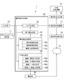
- FIG. 1 is a schematic diagram showing a physical configuration of a processing system 200 according to an embodiment of the present invention.
- the processing system 200 includes an operation command generation device 1 that generates an operation command for the robot 3 based on a protocol chart illustrating a protocol, a robot control device 2 that controls the robot 3 based on the generated operation command, and a robot control. And a robot 3 that is controlled by the apparatus 2 and executes an experiment.
- the operation command generation device 1 itself may be a dedicated device, but here is realized using a general computer. That is, in a commercially available computer, the computer is used as the operation command generation device 1 by executing a computer program that causes the computer to operate as the operation command generation device 1.
- Such a computer program is generally provided in the form of application software, and is used by being installed in a computer.
- the application software may be provided by being recorded on an appropriate computer-readable information recording medium such as a CD-ROM, DVD-ROM, or may be provided through various information communication networks such as the Internet. Alternatively, it may be realized by so-called cloud computing in which the function is provided by a server at a remote place through an information communication network.
- the robot control device 2 is provided integrally with the robot 3 or separately, and executes a desired operation on the robot 3 based on the operation command generated by the operation command generation device 1.
- the robot 3 is an articulated robot and performs processing on a processing target.
- the robot 3 operates an experimental instrument (not shown or illustrated) such as holding and operating the pipette 4 with an arm, holds the microtube 6 stored in the tube shelf 5, and removes the microtube 6 from the tube shelf 5.
- Various containers can be moved such as moving to the main rack 7 or the like.
- the robot 3 moves the microtube 6 to the main rack 7 and performs the processing on the main rack 7 when processing the microtube 6 such as injecting the processing target into the microtube 6. ing.
- the processing system 200 further includes a stirrer 8, a centrifuge 9, and the like. These are examples of instruments used for experiments, and in addition to these instruments.
- the processing system 200 may include a rack for storing Petri dishes, a magnet rack, and the like.
- the robot 3 is not limited to the one shown in the figure, and may be a single arm type robot or the like.
- FIG. 2 is a block diagram showing a physical configuration of the operation command generation device 1 according to the embodiment of the present invention.
- the configuration shown in FIG. 2 shows a general computer used as the operation command generation device 1, and includes a CPU (Central Processing Unit) 1a, a RAM (Random Access Memory) 1b, an external storage device 1c, and a GC (Graphics Controller).
- a CPU Central Processing Unit
- RAM Random Access Memory
- an external storage device 1c a GC (Graphics Controller).
- GC Graphics Controller
- Id input device
- I / O Inpur / Output
- the external storage device 1c is a device capable of recording information statically such as an HDD (Hard Disk Drive) or an SSD (Solid State Drive).
- the signal from the GC 1d is output to a monitor 1h such as a flat panel display where the user visually recognizes the image and displayed as an image.
- the input device 1e is a device such as a keyboard, a mouse, or a touch panel for a user to input information
- the I / O 1f is an interface for the operation command generation device 1 to exchange information with an external device.
- FIG. 3 is a functional block diagram of the operation command generation device 1 according to the present embodiment. Note that the functional blocks shown here are shown paying attention to the functions of the operation command generation device 1, and it is not always necessary that each functional block has a physical configuration corresponding to one-to-one. Some functional blocks are realized by an information processing device such as the CPU 1a of the operation command generation device 1 executing specific software, and some functional blocks are specific to an information storage device such as the RAM 1b of the operation command generation device 1. This may be realized by allocating a storage area.
- the operation command generation device 1 includes an input unit 10 that receives various inputs from a user, and a protocol chart acquisition unit 11 that acquires a protocol chart illustrating a protocol.
- the operation command generation device 1 includes an operation command generation unit 12 that generates an operation command based on the input received by the input unit 10 and the protocol chart acquired by the protocol chart acquisition unit 11, and the acquired protocol chart. And a warning unit 20 that warns when a predetermined description is included. Further, the operation command generation device 1 forms an operation command storage unit 17 that stores electronic data of the generated and generated operation command, and forms the operation command electronic data stored in the operation command storage unit 17 into the monitor 1h.
- the input unit 10 is normally configured by the input device 1e shown in FIG. 2, but when the operation command generation device 1 is an application server used for cloud computing, a user on a remote terminal is used. This corresponds to the I / O 1 f to which the operation information is input.
- the operation command generation unit 12 includes various functional blocks for generating operation commands. Although details will be described later when the operation command generation procedure is described, the operation command generation unit 12 according to the present embodiment associates the processing job indicated by the processing symbol included in the protocol chart with the processing symbol.
- a job generation unit 13 for generating the number of containers is included.
- the operation command generation unit 12 includes an execution order determination unit 14 that determines the execution order of jobs generated by the job generation unit according to the priority order instructed by the priority order instruction unit 15, and an execution order determination unit 14.
- a priority order instructing unit 15 that specifies the priority order of conditions used for determining the job execution order, and an interference determining unit 16 that determines the interference of the process represented by the protocol chart are included.
- an operation command is a single job or a collection of jobs in which a plurality of jobs are combined, and a process that is recognized as one unit for a container that accommodates a processing target. Refers to the command to instruct.
- the operation command is generated by converting each symbol represented in the protocol chart into a job that is a unit operation of the robot, and integrating them while taking into account the execution order of the converted job.
- the priority order instruction unit 15 includes a normal process instruction unit 15a, a continuous process instruction unit 15b, and a repeated process instruction unit 15c.
- the normal process instructing unit 15a instructs the execution order determining unit 14 about the priority of the process that the execution order determining unit 14 should normally determine for a plurality of processing symbols for which continuous processing or repetitive processing described later is not specified.
- the continuous processing instruction unit 15b instructs the execution order determination unit 14 of a priority order specific to continuous processing for a plurality of processing symbols designated for continuous processing.
- the iterative processing instruction unit 15c instructs priority specific to the iterative processing with respect to one or a plurality of processing symbols designated for the iterative processing.
- the interference determining unit 16 includes a continuous / repetitive determining unit 16a, a continuous / non-continuous determining unit 16b, a continuous / general determining unit 16c, and a repeated / repetitive determining unit 16d.
- the continuation / repetition determination unit 16a determines whether or not the group of processing symbols designated for continuous processing and the group of processing symbols designated for repeated processing partially overlap each other.
- the continuous / non-continuous determination unit 16b determines whether one of the group of processing symbols designated for continuous processing and the group of processing symbols designated for exclusion from continuous processing includes the other.
- the continuous / general determination unit 16c determines whether or not a group of processing symbols designated for continuous processing and other processing symbols are arranged in a direction intersecting the direction indicating continuous processing.
- the repetition / repetition determination unit 16d determines whether or not two groups of processing symbols designated for repetition processing partially overlap each other.
- FIG. 4 is a diagram illustrating an example of a protocol chart acquired by the operation command generation device 1 according to the present embodiment.
- the protocol chart refers to a protocol that is illustrated in such a manner that the protocol can be visually understood. It refers to work procedures and conditions such as processing.
- the processing object refers to a material that is an object of an experiment in the same field. In general, it is often a part of a living tissue such as a cell or DNA.
- the treatment object is generally accommodated in an instrument particularly suitable for the experiment, for example, a micro tube (distant pillow tube), a petri dish (petri dish), or a micro plate (micro titer plate). In the case of a simple container, these instruments suitable for accommodating the object to be processed in the experiment are meant.
- the vertical direction in FIG. 4 is referred to as a first direction
- the direction intersecting the first direction is referred to as a second direction.
- the intersection angle between the first direction and the second direction does not necessarily have to be a right angle, but here the first direction and the second direction are assumed to be orthogonal. Therefore, the second direction is the left-right direction in FIG.
- an initial symbol 100 indicating an initial state of a container accommodating a processing target and a final symbol 101 indicating a final state of the container are arranged in a first direction, and both are arranged as initial symbols.
- a processing symbol 103 indicating the individual processing performed on the container is arranged along the order line 102, connected in the first direction by the order line 102 from 100 to the final symbol 101.
- an initial symbol 100 and a final symbol 101 described as “Tube”, and a plurality of processing symbols 103 associated with an order line 102 connecting them are described.
- the order line 102 represents the order in which processing is performed by an arrow line.
- a container number symbol 104 displayed as “ ⁇ 2” superimposed on the initial symbol 100 is described.
- the container number symbol 104 is arranged so as to overlap the initial symbol 100, thereby clearly indicating the association of the initial symbol 100 with a plurality of processing symbols connected by the order line 102.
- the container number symbol 104 represents that the process indicated by the process symbol 103 is performed on two containers. That is, the protocol chart of this example represents a protocol for performing processing indicated by a plurality of processing symbols 103 for two microtubes.
- the processing symbol 103 described as “A”, the processing symbol 103 described as “B”, and the processing symbol 103 described as “C” A processing symbol 103 described as “D” is described.
- the processing symbol 103 described as “A” indicates that the processing A is performed on the microtube under the condition A.
- Specific examples of the process include a process of adding a chemical solution into microtubes, a process of transferring contents between microtubes, a scraping process of acquiring cells cultured on a Petri dish, and the like.
- the processing symbol 103 described as “A” and the processing symbol 103 described as “B” are surrounded by the group symbol 106 and are expressed as “Series ON”.
- the symbols 106a are arranged in an overlapping manner, thereby forming a group of processing symbols for which continuous processing is designated.
- the processing symbol 103 described as “C” and the processing symbol 103 described as “D” are surrounded by a group symbol 106, and a discontinuous processing symbol 106b expressed as “Series OFF” is overlapped. By being arranged, it becomes a group of processing symbols for which exclusion from continuous processing is designated.
- the group symbol 106 is a group of processing symbols 103 that are grouped into one group.
- the group symbol 106 is used when a user who describes a protocol chart collects individual processes and describes a user-defined process.
- the continuous processing symbol 106a represents that the processing indicated by the group of processing symbols designated for continuous processing is continuously performed for each container.
- the discontinuous processing symbol 106b represents that the processing (non-continuous processing) indicated by the group of processing symbols designated to be excluded from the continuous processing is performed on all containers in parallel for each processing.
- a repetition line 105 and a repetition number symbol 105a expressed as “ ⁇ 3” superimposed on the repetition line 105 are described.
- the repetition line 105 represents that the processing indicated by the processing symbol 103 included in the range specified by the repetition line 105 is repeatedly performed by the number represented by the repetition number symbol 105a (repetition processing).
- the repetition line 105 and the repetition number symbol 105a indicate that the processes A, B, C, and D are repeated three times.
- the container number symbol 104 indicates that the processes A, B, C, and D are performed on two microtubes. Therefore, the repetition line 105 and the repetition number symbol 105a are combined. Thus, it is shown that the processes A, B, C, and D are repeated three times for each of the two microtubes.
- iterative processing can be specified along with continuous processing or non-continuous processing.
- a plurality of repeating lines 105 may be arranged for one order line 102, or a group symbol 106 may include a processing symbol 103 surrounded by one or a plurality of group symbols 106.
- both repetitive processing and continuous processing it is necessary to specify so that they do not interfere with each other.
- a plurality of repetition processes it is necessary to specify that the repetition processes do not interfere with each other.
- the group symbol 106 surrounds another group symbol 106, there is an interference between the continuous process and the discontinuous process. It must be specified not to happen.
- the job generation unit 13 sets the number of containers associated with the processing symbol 103 (the number of containers represented by the container number symbol 104) to the processing system 200 for performing the processing indicated by the processing symbol 103. ) Generate. Further, the job generation unit 13 repeatedly generates a job for one or a plurality of processing symbols 103 for which repetition processing is designated, for the number of repetitions (the number of repetitions represented by the repetition number symbol 105a). Therefore, the job generation unit 13 generates, for one processing symbol 103, a number of jobs equal to the product of the number of containers associated with the processing symbol 103 and the number of repetitions specified for the processing symbol 103. .
- the execution order determination unit 14 executes the execution order of jobs generated by the job generation unit 13 by repeating [1] jobs corresponding to the plurality of processing symbols 103 by the number of containers. [2] A job corresponding to each of the plurality of processing symbols 103 is executed in an order corresponding to the arrangement order of each of the plurality of processing symbols 103 in the protocol chart, and [3] a repetition process is designated. Using the condition that the job corresponding to the processing symbol 103 is repeatedly executed for the number of repetitions specified as a batch, the priority is instructed by the priority instruction unit 15. In addition, the priority order instruction unit 15 instructs the execution order determination unit 14 of the priority order of each condition.
- the normal process instruction unit 15a gives an instruction to prioritize [1] over [2] for a plurality of process symbols 103 for which neither continuous process nor repeated process is specified.
- the continuous processing instruction unit 15b instructs the execution order determination unit 14 to prioritize [2] over [1] for a plurality of processing symbols 103 for which continuous processing is specified.
- the repetition processing instruction unit 15c instructs the execution order determination unit 14 to prioritize [1] and [2] over [3] for one or more processing symbols 103 for which repetition processing is specified. .
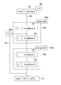
- FIG. 5 is a conceptual diagram showing an operation command generated based on the protocol chart shown in FIG. 4 by the operation command generation device 1 according to the embodiment of the present invention.
- the operation command generation device 1 acquires the protocol chart shown in FIG. 4 by the protocol chart acquisition unit 11 and generates a job that first causes the processing system including the robot 3 to perform the process indicated by the initial symbol 100. (ST10).
- the initial symbol 100 represents a process of arranging the microtubes 6 accommodated in the tube shelf 5 in the main rack 7.
- the container number symbol 104 a job for arranging the two microtubes 6 on the main rack 7 is generated.
- the job generation unit 13 offsets the operation of moving the microtube 6 from the tube shelf 5 and placing it on the main rack 7 with respect to the robot 3 included in the processing system 200 by the arrangement position of the microtube 6. A job to be repeatedly performed on the two microtubes 6 is generated.
- the job generation unit 13 displays the number of containers associated with the processing symbol 103 (represented by the container number symbol 104). Jobs that cause the processing system 200 to perform processing A and processing B are generated for the number of containers 2).
- the execution order determination unit 14 gives priority to the above condition [1] over [2] according to the instruction from the normal processing instruction unit 15a if neither the continuous processing nor the repeated processing is specified for the processing symbol 103. Determine the job execution order.
- the two jobs have one processing symbol 103 (the processing symbol 103 described as “A” or This corresponds to the processing symbol 103) described as “B”. Therefore, in principle, it is prioritized that the processing A and the processing B are performed on the two microtubes 6 rather than the arrangement position of the processing symbol 103, and after the processing A is performed on the two microtubes 6.
- the jobs are generated in the execution order in which the process B is performed on the two microtubes 6.
- the processing symbol 103 described as “A” and the processing symbol 103 described as “B” are a plurality of processing symbols 103 for which continuous processing is designated. Therefore, the continuous processing instruction unit 15b instructs the execution order determination unit 14 to prioritize the above condition [2] over [1]. That is, the continuous processing instruction unit 15b arranges the processing symbol 103 described as “A” on the initial symbol 100 side (upstream side with respect to the order line 102), and sets the processing symbol 103 described as “B” as the final symbol 101.
- the job generating unit 14 causes the processing system 200 to execute a job (ST11) for performing processing A on a single microtube and a job (ST12) for performing processing B to two microtubes. Generate a job that repeats for.
- the job generation unit 13 displays the number of containers associated with the processing symbol 103 (represented by the container number symbol 104). Jobs that cause the processing system 200 to perform processing C and processing D are generated for the number of containers 2).
- the processing symbol 103 described as “C” and the processing symbol 103 described as “D” are a group of processing symbols 103 designated to be excluded from continuous processing.
- the job execution order is determined with priority given to the processes C and D being performed on the two microtubes 6.
- the job generating unit 13 causes the processing system 200 to perform the process C for the two microtubes 6 (ST13) and the job for causing the process D to be performed for the two microtubes 6 (ST14). And generate
- the job generation unit 13 sets the number of repetitions for each repetition.
- a job corresponding to the processing symbol is repeatedly generated.
- the repeat instruction unit 15c instructs the execution order determination unit 14 to prioritize the above conditions [1] and [2] over [3].
- the execution order of the generated jobs is determined based on the conditions [1] and [2] in the repetition count. Which of the conditions [1] and [2] has priority depends on whether an instruction is issued from either the normal processing instruction unit 15a or the continuous processing instruction unit 15b as described above.
- the execution order of the jobs belonging to the next number of repetitions is similarly determined. In this way, the job corresponding to the processing symbol for which the repetition process is designated is repeatedly executed for the number of repetitions designated as a batch.
- the job generation unit 13 generates a job for causing the processing system 200 to store the two microtubes 6 in a constant temperature bath of 4 ° C. (S15).
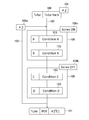
- FIG. 6 is a flowchart of an operation command generated based on the protocol chart shown in FIG. 4 by the operation command generation device 1 according to the embodiment of the present invention.
- the operation command generated based on the protocol chart shown in FIG. 4 is a job for moving the first microtube (the first microtube 6 accommodated in the tube shelf 5) from the tube shelf 5 and arranging it on the main rack 7. Start from (ST20). Subsequently, a job (ST21) is executed in which the second microtube (the second microtube 6 accommodated in the tube shelf 5) is moved from the tube shelf 5 and placed on the main rack 7.
- a job for performing process A on the first microtube is executed (ST22), and a job for performing process B on the first microtube is executed (ST23).
- a job for performing the process A for the second microtube is executed (ST24), and a job for performing the process B for the second microtube is executed (ST25).
- a job for performing process C on the first microtube is executed (ST26), and a job for performing process C on the second microtube is executed. (ST27). Further, a job for performing the process D for the first microtube is executed (ST28), and a job for performing the process D for the second microtube is executed (ST29).
- a job generated by the job generation unit 13 includes a command for repeating a group of processes designated for continuous processing for the number of containers, a command for repeating a group of processes designated for repeated processing for the number of repetitions, A second level including a first level job including a command to repeat individual processes other than a group of processes for which continuous processing is designated for the number of containers, and a command to perform a group of processes for which continuous processing is designated once Job.
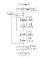
- FIG. 7 shows a flow of a job generated intermediately when the operation command generation apparatus 1 according to the present embodiment generates the operation command flow shown in FIG. 6 based on the protocol chart shown in FIG. FIG.
- the protocol chart is smoothly converted into an operation command by dividing the job into a first level job and a second level job and forming a hierarchical structure.
- the first level job is shown on the left side and the second level job is shown on the right side to show the hierarchical structure of the job.
- the initial symbol 100 included in the protocol chart of FIG. 4 is converted into a job for preparing a microtube as a second level job (ST40).
- the number of containers being two means that this job is converted into an operation command that is repeatedly performed on two containers.
- the continuous processing symbol 106a is converted into a continuous processing command which is a first level job (ST41).
- the continuous processing command indicates that the second level job belonging to the continuous processing command is repeated for the container numbers 1 and 2.
- the second level jobs belonging to the continuous processing command are the job (ST42) for performing the process A and the job (ST43) for performing the process B, and these have a number of containers of 1 and are repeatedly operated on a plurality of containers. Do not do.
- the number of the container for which the process A and the process B are targeted is designated by a continuous process command. That is, the continuous processing command is a command for repeatedly calling a second level job having the number of containers of 1 by sequentially specifying the container numbers.
- the process A and the process B are sequentially called for the container number 1 by the continuous process command, and then are sequentially called for the container number 2, thereby determining the order of the continuous process.
- the repetitive processing command is a command for returning the processing to the top of the range in which the repetitive designation is made by the number of times of repetition.
- the repetitive processing command indicates that the second level job belonging to the repetitive processing command is repeated 1 to 3 times.
- the second level jobs belonging to the repetitive processing command are processing A and processing B for which a continuous processing command has been issued, and processing C and processing D, which are normal processing.
- the second level job within the range in which the repetition process is designated is repeated the number of repetitions, and the order of repetition is determined.
- the final symbol 101 is converted into a job containing a microtube as a second level job (ST47).
- the number of containers being two means that this job is converted into an operation command that is repeatedly performed on two containers.
- the first level job is a command that is indirectly converted into an operation command by calling the second level job.
- the second level job is a command that is directly converted into a job of the robot 3. In this way, by using a hierarchical data structure, it is possible to utilize a second level job prepared as a command group that is directly converted into an operation command without using a second level job, and to perform continuous processing, repeated processing, etc. Advanced control can be realized.
- the job generation unit 13 includes a continuous processing job generation unit, a repetitive processing job generation unit, and an individual processing job generation unit.
- the continuous processing job generation unit generates a job that causes the processing system 200 to repeat the processing indicated by the plurality of processing symbols 103 for which the continuous processing is designated by the number of containers (the number represented by the container number symbol 104).
- the iterative processing job generating unit generates a job that causes the processing system 200 to repeat the processing indicated by the one or more processing symbols 103 for which the iterative processing is designated by the number of repetitions (repetition number symbol 105a).
- the individual processing job generation unit generates a job that causes the processing system 200 to repeat the processing indicated by the processing symbol 103 for which continuous processing is not specified for the number of containers, and the processing indicated by the processing symbol 103 for which continuous processing is specified. Is generated by the processing system 200 once. Thereby, the job generation unit 13 generates hierarchized jobs of the first level job and the second level job, systematic job generation is performed, and job management becomes easy.
- the job execution order is determined based on the arrangement position in the second direction.
- the job execution order is determined so that the processing indicated by the processing symbol 103 arranged on the left side of the protocol chart is preferentially executed.
- an operation command for efficiently operating the robot 3 is automatically generated when the same processing is repeatedly performed on a plurality of containers. Further, when the same process is repeatedly performed on a plurality of containers, an operation command is automatically generated by offsetting the arm position of the robot 3 for each container and repeating the same process by the number of containers. Furthermore, based on a protocol chart including a plurality of processing symbols 103 for which continuous processing is designated, an operation command for performing continuous processing for each container is automatically generated.
- the operation command generation device 1 automatically generates an operation command for performing repetitive processing based on a protocol chart including one or more processing symbols 103 for which repetitive processing is specified.
- the repetition process is represented by arranging the repetition line 105 and the repetition number symbol 105a in the protocol chart.
- an operation command for performing repetition processing is automatically generated based on a protocol chart briefly described using the repetition line 105 and the repetition number symbol 105a. .
- FIG. 8 is a diagram illustrating a first example of a protocol chart displayed as a warning by the operation command generation device 1 according to the embodiment of the present invention.
- the repetition line 105 is arranged between the processing symbol 103 described as “A” and the processing symbol 103 described as “B”.
- the repetition line 105 is arranged between the initial symbol 100 and the processing symbol 103 described as “A”.
- the repetition line 105 is arranged between a group of processing symbols 103 (processing symbol 103 described as “A” and processing symbol 103 described as “B”) in which continuous processing is designated. Has been. Therefore, after processing A, processing B, processing C, and processing D are performed once, processing B and subsequent processing are repeated. However, since processing A and processing B are designated as continuous processing, only processing B is performed. Is not compatible with the designation of the continuous processing.
- the continuous / repetitive determination unit 16a includes a group of processing symbols designated for continuous processing, and a group of processing symbols designated for repeated processing. Determine whether or not they partially overlap each other.
- the continuation / repetition determination unit 16a includes a group of processing symbols (processing symbol 103 described as “A” and processing symbol 103 described as “B”) designated for continuous processing, and , A group of processing symbols designated for repeated processing (processing symbol 103 described as “B”, processing symbol 103 described as “C”, and processing symbol 103 described as “D”) are: It is determined that the processing symbols 103 described as “B” partially overlap each other.
- the warning unit 20 Upon receiving the determination by the continuous / repetitive determination unit 16a, the warning unit 20 warns the user of the operation command generation device 1.
- the warning is performed, for example, by displaying a warning text on the monitor 1h.
- the warning unit 20 issues a warning when the job generation unit 13 generates a job.
- the timing at which the warning unit 20 issues a warning does not necessarily have to be when the motion command generation device 1 generates a motion command to be read by the robot control device 2, and the motion command generation device 1 operates based on the protocol chart. It may be time to simulate the generation of commands.
- a warning is issued when the designation of continuous processing and the designation of repeated processing are not compatible, and interference between the continuous processing and the repeated processing is prevented.
- the user of the operation command generation device 1 can receive a warning that interference between continuous processing and repetitive processing, edit the protocol chart, and describe a consistent protocol. Further, the user of the operation command generation device 1 can freely edit the protocol chart without being bothered by unnecessary warnings until the time of generating a job.
- FIG. 9 is a diagram illustrating a second example of a protocol chart displayed as a warning by the operation command generation device 1 according to the embodiment of the present invention.
- the group symbol 106 associated with the non-continuous processing symbol 106b is arranged inside the group symbol 106 associated with the continuous processing symbol 106a.
- a group of processing symbols 103 (processing symbol 103 described as “A”, processing symbol 103 described as “B”, and “C” described as continuous processing is specified.
- a processing symbol 103 and a processing symbol 103 described as “D” are described as a group of processing symbols 103 (“B” processing symbol 103 and “C”) that are designated to be excluded from continuous processing. Processing symbols 103). Therefore, for the processing symbol 103 described as “B” and the processing symbol 103 described as “C”, designation of continuous processing and designation of exclusion from continuous processing are not compatible.
- the continuous / non-continuous determination unit 16b is based on the protocol chart acquired by the protocol chart acquisition unit 11, a group of processing symbols designated for continuous processing, and a group designated for exclusion from continuous processing. Whether one of the processing symbols includes the other is determined.
- the continuous / non-continuous determination unit 16b includes a group of processing symbols (processing symbol 103 described as “A” and processing symbol 103 described as “B”) for which continuous processing is designated.
- the warning unit 20 Upon receiving the determination by the continuous / non-continuous determination unit 16b, the warning unit 20 warns the user of the operation command generation device 1 by displaying a warning text on the monitor 1h, for example.
- the warning unit 20 may issue a warning when the job generation unit 13 generates a job.
- a warning is issued when the designation of continuous processing and the designation of discontinuous processing are not compatible, and interference between continuous processing and discontinuous processing is prevented.
- the user of the operation command generation device 1 can receive a warning that the continuous process and the non-continuous process interfere, edit the protocol chart, and describe a protocol with no contradiction. Further, the user of the operation command generation device 1 can freely edit the protocol chart without being bothered by unnecessary warnings until the time of generating a job.
- FIG. 10 is a diagram showing a third example of a protocol chart displayed as a warning by the operation command generation device 1 according to the embodiment of the present invention.
- the protocol chart shown in FIG. 10 is a protocol in which processing A and processing B are successively performed on each of two microtubes, and then processing C is performed, and processing D and processing E are performed on one microtube. Represents the protocol to be performed.
- the operation command generation device 1 refers to the arrangement position of the processing symbol 103 in the protocol chart when the execution order determination unit 14 determines the job execution order.
- the execution order determination unit 14 performs the second direction (in the first direction).
- the job execution order is determined based on the arrangement position in the intersecting direction (the horizontal direction in FIG. 10). Specifically, the operation command generation device 1 according to the present embodiment determines the job execution order so that the processing indicated by the processing symbol 103 arranged on the left side of the protocol chart is performed earlier.
- the execution of the process C is given priority, and after the process C is performed on the two microtubes, the operation command for performing the process E on the other one microtube. Is generated.
- the processing symbol 103 described as “A” and the processing symbol 103 described as “D” are arranged in the second direction intersecting the first direction (direction indicating continuous processing).
- the instruction for continuous processing for process A and process B is not compatible with the instruction for performing process D after process A.
- a group of processing symbols designated for continuous processing and other processing symbols indicate continuous processing based on the protocol chart acquired by the protocol chart acquisition unit 11. It is determined whether or not they are arranged in a direction crossing the direction.
- the continuous / general determination unit 16c is a group of processing symbols designated for continuous processing (a processing symbol 103 described as “A” and a processing symbol 103 described as “B”). And other processing symbols (processing symbols 103 described as “D”) are determined to be arranged in a direction (horizontal direction in the protocol chart shown in FIG. 10) intersecting the direction indicating the continuous processing.
- the warning unit 20 Upon receiving the determination by the continuous / general determination unit 16c, the warning unit 20 warns the user of the operation command generation device 1 by displaying a warning text on the monitor 1h, for example.
- the warning unit 20 may issue a warning when the job generation unit 13 generates a job.
- a warning is issued when a continuous processing instruction and a general processing instruction are incompatible, and interference between the continuous processing and the general processing is prevented.
- the user of the operation command generation device 1 receives a warning that the continuous process and the general process interfere with each other, and can edit the protocol chart to describe a protocol having no contradiction. Further, the user of the operation command generation device 1 can freely edit the protocol chart without being bothered by unnecessary warnings until the time of generating a job.
- FIG. 11 is a diagram showing a fourth example of a protocol chart displayed as a warning by the operation command generation device 1 according to the embodiment of the present invention.
- a repeating line 105 of books is arranged.
- a group of processing symbols 103 (processing symbol 103 described as “A” and processing symbol 103 described as “B”) for which iterative processing is designated is designated as another iteration processing.
- the group of processed symbols 103 (the processed symbol 103 described as “B”, the processed symbol 103 described as “C”, and the processed symbol 103 described as “D”) are expressed as “B”.
- the described processing symbol 103 is duplicated.
- the instruction to repeat process A and process B three times and the instruction to repeat process B, process C and process D four times are not compatible.
- the repetition / repetition determination unit 16d determines whether or not two groups of processing symbols designated for repetition processing partially overlap each other based on the protocol chart acquired by the protocol chart acquisition unit 11. Determine.
- the repetition / repetition determination unit 16d has a group of processing symbols (processing symbol 103 described as “A” and processing symbol 103 described as “B”) designated for repetition processing, and , A group of processing symbols designated for repeated processing (processing symbol 103 described as “B”, processing symbol 103 described as “C”, and processing symbol 103 described as “D”) are mutually connected. Judged as partially overlapping.
- the warning unit 20 Upon receiving the determination by the repetition / repetition determination unit 16d, the warning unit 20 warns the user of the operation command generation device 1 by displaying a warning text on the monitor 1h, for example.
- the warning unit 20 may issue a warning when the job generation unit 13 generates a job.
- a warning is issued when two repeated processes are specified in a partially overlapping manner, and interference between the repeated processes is prevented.
- the user of the operation command generation device 1 can receive a warning that the repetitive processes interfere with each other, edit the protocol chart, and describe a protocol with no contradiction. Further, the user of the operation command generation device 1 can freely edit the protocol chart without being bothered by unnecessary warnings until the time of generating a job.
Abstract
An action command generation device generates an action command, which is a collection of jobs to be performed by a processing system (200) including a robot (3), on the basis of a protocol chart containing a plurality of process symbols. The action command generation device comprises a priority instruction unit (15) for indicating the priority of conditions for determining the order of execution of jobs, and an execution order determination unit (14) for determining, when a plurality of containers are present, the order of execution of jobs created by a job creation unit according to the priority indicated by the priority instruction unit (15) using the following conditions: [1] jobs corresponding to the respective process symbols are repeated the same number of times as the number of the containers; and [2] the jobs corresponding to the respective process symbols are performed in the order corresponding to the sequence of the process symbols in the protocol chart. The action command generation device automatically generates an action command for causing the processing system including the robot to perform an experiment based on the protocol.
Description
本発明は、動作指令生成装置、動作指令生成方法、コンピュータプログラム、及び処理システムに関する。
The present invention relates to an operation command generation device, an operation command generation method, a computer program, and a processing system.
生化学や生物/生命工学の分野における、一連の検査や培養、増幅といった処理対象に対してする操作(以降、これらを一まとめにして「実験」と称する。)の作業手順や条件は一般にプロトコルと呼びならわされている。プロトコルは、実験について再現性のある結果を得、或いはその実験結果の検証を行う上で必要な情報である。
In the fields of biochemistry and biology / biotechnology, the procedures and conditions for a series of tests, operations, and operations (hereinafter referred to as “experiment”) for processing objects such as culture and amplification are generally protocols. It is called. The protocol is information necessary to obtain a reproducible result for the experiment or to verify the experiment result.
本発明は、プロトコルに基づく実験を、ロボットを含む処理システムに行わせるための動作指令を自動的に生成することをその課題とする。
The object of the present invention is to automatically generate an operation command for causing a processing system including a robot to perform an experiment based on a protocol.
本発明の一の側面による動作指令生成装置は、処理対象を収容した容器に対する処理を表す複数の処理シンボルを少なくとも含むプロトコルチャートに基づいて、少なくともロボットを含む処理システムに行わせるジョブの集合体である動作指令を生成する動作指令生成装置であって、前記プロトコルチャートに基づいて、前記複数の処理シンボルそれぞれが示す処理のジョブを生成するジョブ生成部と、ジョブの実行順を決定する条件の優先順位を指示する優先順位指示部と、前記容器が複数ある場合に、前記ジョブ生成部により生成されるジョブの実行順を、少なくとも、[1]前記複数の処理シンボルそれぞれに対応するジョブが前記容器の数だけ繰返されて実行されること、[2]前記プロトコルチャートにおける前記複数の処理シンボルそれぞれの配置順番に対応した順番で前記複数の処理シンボルそれぞれに対応するジョブが実行されること、の条件を用い、前記優先順位指示部により指示された優先順位で決定する実行順決定部と、を有する。
An operation command generation device according to one aspect of the present invention is a collection of jobs to be executed by a processing system including at least a robot based on a protocol chart including at least a plurality of processing symbols representing processing for a container that stores a processing target. An operation command generation device that generates a certain operation command, and based on the protocol chart, a job generation unit that generates a job of a process indicated by each of the plurality of processing symbols, and a priority of a condition for determining a job execution order In the case where there are a plurality of containers and a priority order instructing unit for instructing the order, the execution order of jobs generated by the job generating unit is set to at least [1] jobs corresponding to the plurality of processing symbols are the containers. And [2] the plurality of processes in the protocol chart. An execution order determination unit that determines a job according to each of the plurality of processing symbols in the order corresponding to the arrangement order of each of the symbols, and determines the priority according to the priority specified by the priority instruction unit; Have.
また、本発明の別の側面による動作指令生成装置では、前記優先順位指示部は、前記条件[1]を[2]に優先させる指示をする通常処理指示部と、連続処理を指定された複数の前記処理シンボルについて、前記条件[2]を[1]に優先させる指示をする連続処理指示部と、を有してよい。
In the operation command generation device according to another aspect of the present invention, the priority order instruction unit includes a normal process instruction unit that gives an instruction to prioritize the condition [1] over [2], and a plurality of continuous processes specified. A continuous processing instruction unit for giving an instruction to prioritize the condition [2] over [1] for the processing symbols.
また、本発明の別の側面による動作指令生成装置では、前記ジョブ生成部は、さらに、繰返し処理を指定された1又は複数の前記処理シンボルについて、前記処理シンボルそれぞれに対応するジョブを、繰返し数だけ生成し、前記実行順決定部は、さらに、[3]繰返し処理を指定された処理シンボルに対応するジョブが、一括として指定された繰返し数だけ繰返し実行されること、の条件を有し、前記優先順位指示部は、前記条件[1]及び[2]を[3]に優先させる指示をする繰返し処理指示部をさらに有してよい。
In the operation command generation device according to another aspect of the present invention, the job generation unit further, for one or a plurality of the processing symbols designated for repetition processing, a job corresponding to each of the processing symbols, The execution order determination unit further has a condition that [3] a job corresponding to a processing symbol for which repetition processing is specified is repeatedly executed by the number of repetitions specified as a batch, The priority order instructing unit may further include an iterative process instructing unit that gives an instruction to prioritize the conditions [1] and [2] over [3].
また、本発明の別の側面による動作指令生成装置では、連続処理を指定された一群の前記処理シンボルと、繰返し処理を指定された一群の前記処理シンボルとが、互いに部分的に重複する場合に、警告する警告部をさらに有してもよい。
In the operation command generation device according to another aspect of the present invention, a group of the processing symbols designated for continuous processing and a group of the processing symbols designated for repeated processing partially overlap each other. A warning unit for warning may be further included.
また、本発明の別の側面による動作指令生成装置では、前記警告部は、連続処理を指定された一群の前記処理シンボルと、連続処理からの除外が指定された一群の前記処理シンボルとの一方が他方を包含する場合に、警告してよい。
In the operation command generation device according to another aspect of the present invention, the warning unit includes one of the group of processing symbols designated for continuous processing and the group of processing symbols designated for exclusion from continuous processing. May warn if it includes the other.
また、本発明の別の側面による動作指令生成装置では、前記警告部は、繰返し処理を指定された2の一群の前記処理シンボルが、互いに部分的に重複する場合に、警告してよい。
In the operation command generation device according to another aspect of the present invention, the warning unit may warn when two groups of the processing symbols designated for repeated processing partially overlap each other.
また、本発明の別の側面による動作指令生成装置では、前記警告部は、連続処理を指定された一群の前記処理シンボルと、他の前記処理シンボルとが、連続処理を示す方向に交差する方向に配置されている場合に、警告してよい。
In the operation command generation device according to another aspect of the present invention, the warning unit is configured such that a group of the processing symbols designated for continuous processing and the other processing symbols intersect a direction indicating continuous processing. May be warned if placed in
また、本発明の別の側面による動作指令生成装置では、前記警告部は、前記ジョブ生成部がジョブを生成する時に、警告を発してよい。
In the operation command generation device according to another aspect of the present invention, the warning unit may issue a warning when the job generation unit generates a job.
また、本発明の別の側面による動作指令生成装置では、前記ジョブ生成部により生成されるジョブは、連続処理を指定された一群の処理を容器数分繰り返す指令と、繰り返し処理を指定された一群の処理を繰り返し数分繰り返す指令と、を含む第1レベルジョブと、連続処理を指定された一群の処理以外の個々の処理を容器数分繰り返す指令と、連続処理を指定された一群の処理を1度行う指令とを含む第2レベルジョブと、を含んでよい。
In the operation command generation device according to another aspect of the present invention, the job generated by the job generation unit includes a command for repeating a group of processes designated for continuous processing by the number of containers, and a group for designated repetition processing. A first level job including a process for repeating the process for a number of times, a command for repeating individual processes other than the group of processes for which the continuous process is designated for the number of containers, and a group of processes for which the continuous process is designated. And a second level job including a command to be executed once.
また、本発明の別の側面によるコンピュータプログラムは、コンピュータを、上述の動作指令生成装置として機能させる。
Also, a computer program according to another aspect of the present invention causes a computer to function as the above-described operation command generation device.
また、本発明の別の側面による動作指令作成方法は、処理対象を収容した容器に対する処理を表す複数の処理シンボルを少なくとも含むプロトコルチャートに基づいて、少なくともロボットを含む処理システムに行わせるジョブの集合体である動作指令を生成する動作指令生成方法であって、前記プロトコルチャートに基づいて、前記複数の処理シンボルそれぞれが示す処理のジョブを生成し、ジョブの実行順を決定する条件の優先順位を指示し、前記容器が複数ある場合に、前記ジョブ生成部により生成されるジョブの実行順を、少なくとも、[1]前記複数の処理シンボルそれぞれに対応するジョブが前記容器の数だけ繰返されて実行されること、[2]前記プロトコルチャートにおける前記複数の処理シンボルそれぞれの配置順番に対応した順番で前記複数の処理シンボルそれぞれに対応するジョブが実行されること、の条件を用い、指示された優先順位で決定する。
According to another aspect of the present invention, there is provided an operation command generation method comprising a set of jobs to be executed by a processing system including at least a robot based on a protocol chart including at least a plurality of processing symbols representing processing for a container containing a processing target. An operation command generation method for generating an operation command that is a body, wherein a job of a process indicated by each of the plurality of process symbols is generated based on the protocol chart, and a priority order of conditions for determining a job execution order is set When there are a plurality of containers, the execution order of jobs generated by the job generation unit is at least [1] jobs corresponding to the plurality of processing symbols are repeated and executed by the number of containers. [2] In the arrangement order of the plurality of processing symbols in the protocol chart The job corresponding to each of the plurality of processing symbols in response to the order is executed, the conditions used for, is determined at the indicated priority.
また、本発明の別の側面による処理システムは、上述の動作指令生成装置と、前記動作指令生成装置により生成された動作指令に基づき制御対象を制御するロボット制御装置と、前記ロボット制御装置の制御対象に含まれ、1又は2以上のアームで処理対象に対する処理を行うロボットと、を有する。
In addition, a processing system according to another aspect of the present invention includes the above-described operation command generation device, a robot control device that controls a control object based on the operation command generated by the operation command generation device, and control of the robot control device. And a robot that is included in the target and performs processing on the processing target with one or more arms.
本発明の発明者の知見によれば、生化学、生物/生命工学における実験において、所期の結果を得られる可能性、すなわち、実験の再現性は、実験者の技量に依存する部分が大きく、実験結果の信頼性の検証等に支障をきたす場合がある。そこで、発明者は、実験をロボットを用いて実施することで、人為的要因を排除することを検討している。
According to the knowledge of the inventor of the present invention, the possibility of obtaining the expected result in the experiment in biochemistry and biological / biotechnology, that is, the reproducibility of the experiment largely depends on the skill of the experimenter. In some cases, the verification of the reliability of the experimental results may be hindered. Therefore, the inventor is considering removing an artificial factor by performing an experiment using a robot.
しかしながら、これまで、プロトコルを記述する定まった書式は確立されておらず、それぞれの実験者が独自の書式でプロトコルを記述しているとみられる。そのため、あるプロトコルに基づいてロボットの動作を記述しようとすると、そのプロトコルとロボットの動作のプログラミングの両方に精通した技術者が必要となり、また、プロトコルの書式が変わると対応できなくなるなど、プロトコルに基づいてロボットの動作を記述することは、実用上非現実的である。
However, until now, no fixed format for describing the protocol has been established, and it seems that each experimenter describes the protocol in its own format. For this reason, describing a robot's motion based on a protocol requires an engineer who is familiar with both that protocol and the robot's motion programming. It is practically impractical to describe the behavior of the robot based on it.
そこで、本発明者は、プロトコルに基づく実験をロボットに行わせるための動作指令を自動的に生成することについて鋭意研究開発を行い、新規かつ独創的な動作指令生成装置等を発明するに至った。以下、かかる動作指令生成装置等について、実施形態を例示して説明する。
Therefore, the present inventor has conducted earnest research and development on automatically generating an operation command for causing a robot to perform an experiment based on a protocol, and has invented a new and original operation command generation device and the like. . Hereinafter, such an operation command generation device and the like will be described by exemplifying embodiments.
図1は、本発明の実施形態に係る処理システム200の物理的な構成を示す概略図である。処理システム200は、プロトコルを図示したプロトコルチャートに基づき、ロボット3の動作指令を生成する動作指令生成装置1と、生成された動作指令に基づき、ロボット3を制御するロボット制御装置2と、ロボット制御装置2により制御され、実験を実行するロボット3とを含む。動作指令生成装置1自体は、専用の機器であってもよいが、ここでは一般的なコンピュータを使用して実現されている。すなわち、市販のコンピュータにおいて、当該コンピュータを動作指令生成装置1として動作させるコンピュータプログラムを実行することによりかかるコンピュータを動作指令生成装置1として使用する。かかるコンピュータプログラムは、一般にアプリケーションソフトウェアの形で提供され、コンピュータにインストールされて使用される。当該アプリケーションソフトウェアは、CD-ROMやDVD-ROMその他のコンピュータ読み取り可能な適宜の情報記録媒体に記録されて提供されてよく、また、インターネット等の各種の情報通信ネットワークを通じて提供されてもよい。あるいは、情報通信ネットワークを通じて遠隔地にあるサーバによりその機能が提供される、いわゆるクラウドコンピューティングにより実現されてもよい。また、ロボット制御装置2は、ここではロボット3と一体となって、又は別体に設けられており、動作指令生成装置1により生成された動作指令に基いて、ロボット3に所望の動作を実行させる。
FIG. 1 is a schematic diagram showing a physical configuration of a processing system 200 according to an embodiment of the present invention. The processing system 200 includes an operation command generation device 1 that generates an operation command for the robot 3 based on a protocol chart illustrating a protocol, a robot control device 2 that controls the robot 3 based on the generated operation command, and a robot control. And a robot 3 that is controlled by the apparatus 2 and executes an experiment. The operation command generation device 1 itself may be a dedicated device, but here is realized using a general computer. That is, in a commercially available computer, the computer is used as the operation command generation device 1 by executing a computer program that causes the computer to operate as the operation command generation device 1. Such a computer program is generally provided in the form of application software, and is used by being installed in a computer. The application software may be provided by being recorded on an appropriate computer-readable information recording medium such as a CD-ROM, DVD-ROM, or may be provided through various information communication networks such as the Internet. Alternatively, it may be realized by so-called cloud computing in which the function is provided by a server at a remote place through an information communication network. Here, the robot control device 2 is provided integrally with the robot 3 or separately, and executes a desired operation on the robot 3 based on the operation command generated by the operation command generation device 1. Let
ロボット3は、多関節ロボットであり、処理対象に対する処理を行う。ロボット3は、アームによりピペット4を把持し操作する等、図示しあるいは図示しない実験器具を操作し、また、チューブ棚5に格納されたマイクロチューブ6を把持し、マイクロチューブ6をチューブ棚5からメインラック7等へ移動させるなど、図示しあるいは図示しない各種容器を移動させることができる。本実施形態では、ロボット3は、処理対象をマイクロチューブ6に注入する等、マイクロチューブ6に対する処理を行う場合、メインラック7にマイクロチューブ6を移動させ、メインラック7上で処理を行うようにしている。図1に示す例では、処理システム200には、さらに、撹拌機8と、遠心分離器9等が含まれるが、これらは実験を行う場合に用いられる器具の一例であり、これらの器具に加えて又は換えて、他の器具が含まれてもよい。例えば、処理システム200には、ペトリ皿を保管するラックや、マグネットラック等が含まれてもよい。また、ロボット3は図示した形態のものに限られず、単腕型ロボット等であってもよい。
The robot 3 is an articulated robot and performs processing on a processing target. The robot 3 operates an experimental instrument (not shown or illustrated) such as holding and operating the pipette 4 with an arm, holds the microtube 6 stored in the tube shelf 5, and removes the microtube 6 from the tube shelf 5. Various containers (not shown or illustrated) can be moved such as moving to the main rack 7 or the like. In the present embodiment, the robot 3 moves the microtube 6 to the main rack 7 and performs the processing on the main rack 7 when processing the microtube 6 such as injecting the processing target into the microtube 6. ing. In the example shown in FIG. 1, the processing system 200 further includes a stirrer 8, a centrifuge 9, and the like. These are examples of instruments used for experiments, and in addition to these instruments. Alternatively, other instruments may be included. For example, the processing system 200 may include a rack for storing Petri dishes, a magnet rack, and the like. The robot 3 is not limited to the one shown in the figure, and may be a single arm type robot or the like.
図2は、本発明の実施形態に係る動作指令生成装置1の物理的な構成を示すブロック図である。図2に示した構成は、動作指令生成装置1として用いられる一般的なコンピュータを示しており、CPU(Central Processing Unit)1a、RAM(Random Access Memory)1b、外部記憶装置1c、GC(Graphics Controller)1d、入力デバイス1e及びI/O(Inpur/Output)1fがデータバス1gにより相互に電気信号のやり取りができるよう接続されている。ここで、外部記憶装置1cはHDD(Hard Disk Drive)やSSD(Solid State Drive)等の静的に情報を記録できる装置である。またGC1dからの信号はフラットパネルディスプレイ等の、使用者が視覚的に画像を認識するモニタ1hに出力され、画像として表示される。入力デバイス1eはキーボードやマウス、タッチパネル等の、ユーザが情報を入力するための機器であり、I/O1fは動作指令生成装置1が外部の機器と情報をやり取りするためのインタフェースである。
FIG. 2 is a block diagram showing a physical configuration of the operation command generation device 1 according to the embodiment of the present invention. The configuration shown in FIG. 2 shows a general computer used as the operation command generation device 1, and includes a CPU (Central Processing Unit) 1a, a RAM (Random Access Memory) 1b, an external storage device 1c, and a GC (Graphics Controller). ) 1d, an input device 1e and an I / O (Inpur / Output) 1f are connected to each other via a data bus 1g so that electrical signals can be exchanged. Here, the external storage device 1c is a device capable of recording information statically such as an HDD (Hard Disk Drive) or an SSD (Solid State Drive). The signal from the GC 1d is output to a monitor 1h such as a flat panel display where the user visually recognizes the image and displayed as an image. The input device 1e is a device such as a keyboard, a mouse, or a touch panel for a user to input information, and the I / O 1f is an interface for the operation command generation device 1 to exchange information with an external device.
図3は、本実施形態に係る動作指令生成装置1の機能ブロック図である。なお、ここで示した機能ブロックは、動作指令生成装置1が有する機能に着目して示したものであり、必ずしも各機能ブロックに1対1に対応する物理的構成が存在することを要しない。いくらかの機能ブロックは動作指令生成装置1のCPU1a等の情報処理装置が特定のソフトウェアを実行することにより実現され、またいくらかの機能ブロックは動作指令生成装置1のRAM1b等の情報記憶装置に特定の記憶領域が割り当てられることにより実現されてよい。
FIG. 3 is a functional block diagram of the operation command generation device 1 according to the present embodiment. Note that the functional blocks shown here are shown paying attention to the functions of the operation command generation device 1, and it is not always necessary that each functional block has a physical configuration corresponding to one-to-one. Some functional blocks are realized by an information processing device such as the CPU 1a of the operation command generation device 1 executing specific software, and some functional blocks are specific to an information storage device such as the RAM 1b of the operation command generation device 1. This may be realized by allocating a storage area.
動作指令生成装置1は、ユーザからの各種の入力を受け付ける入力部10と、プロトコルを図示したプロトコルチャートを取得するプロトコルチャート取得部11とを有する。また、動作指令生成装置1は、入力部10により受けつけられた入力、及びプロトコルチャート取得部11により取得されたプロトコルチャートに基づいて動作指令を生成する動作指令生成部12と、取得されたプロトコルチャートが所定の記述を含む場合に警告する警告部20とを有する。さらに、動作指令生成装置1は、生成中及び生成された動作指令の電子データを記憶する動作指令記憶部17と、動作指令記憶部17に記憶された動作指令の電子データを成形しモニタ1hに表示する動作指令表示部19と、生成された動作指令をロボットが読み取り可能な形式の電子ファイルとして出力する動作指令出力部18とを有する。
The operation command generation device 1 includes an input unit 10 that receives various inputs from a user, and a protocol chart acquisition unit 11 that acquires a protocol chart illustrating a protocol. The operation command generation device 1 includes an operation command generation unit 12 that generates an operation command based on the input received by the input unit 10 and the protocol chart acquired by the protocol chart acquisition unit 11, and the acquired protocol chart. And a warning unit 20 that warns when a predetermined description is included. Further, the operation command generation device 1 forms an operation command storage unit 17 that stores electronic data of the generated and generated operation command, and forms the operation command electronic data stored in the operation command storage unit 17 into the monitor 1h. An operation command display unit 19 for displaying and an operation command output unit 18 for outputting the generated operation command as an electronic file in a format that can be read by the robot.
入力部10は、通常は図2に示した入力デバイス1eにより構成されるが、動作指令生成装置1がクラウドコンピューティングに用いられるアプリケーションサーバである場合には、遠隔地にある端末上でのユーザの操作情報が入力されるI/O1fが該当することになる。
The input unit 10 is normally configured by the input device 1e shown in FIG. 2, but when the operation command generation device 1 is an application server used for cloud computing, a user on a remote terminal is used. This corresponds to the I / O 1 f to which the operation information is input.
動作指令生成部12には動作指令を生成するための種々の機能ブロックが含まれる。詳細は後ほど動作指令の生成手順を説明する際に合わせて説明するが、本実施形態に係る動作指令生成部12には、プロトコルチャートに含まれる処理シンボルが示す処理のジョブを、処理シンボルに関連付けられた容器数生成するジョブ生成部13が含まれる。また、動作指令生成部12には、ジョブ生成部により生成されるジョブの実行順を、優先順位指示部15に指示された優先順位に従って決定する実行順決定部14と、実行順決定部14がジョブの実行順を決定するにあたって用いる条件の優先順位を指定する優先順位指示部15と、プロトコルチャートにより表される処理の干渉を判定する干渉判定部16とが含まれる。
The operation command generation unit 12 includes various functional blocks for generating operation commands. Although details will be described later when the operation command generation procedure is described, the operation command generation unit 12 according to the present embodiment associates the processing job indicated by the processing symbol included in the protocol chart with the processing symbol. A job generation unit 13 for generating the number of containers is included. The operation command generation unit 12 includes an execution order determination unit 14 that determines the execution order of jobs generated by the job generation unit according to the priority order instructed by the priority order instruction unit 15, and an execution order determination unit 14. A priority order instructing unit 15 that specifies the priority order of conditions used for determining the job execution order, and an interference determining unit 16 that determines the interference of the process represented by the protocol chart are included.
なお、本明細書において、動作指令とは、単一のジョブ又は複数のジョブが組み合わされたジョブの集合体であって、処理対象が収容される容器に対する一単位のものとして認識される処理を指示する指令をいうものとする。動作指令は、プロトコルチャートに表された個々のシンボルをロボットの単位動作であるジョブに変換し、変換されたジョブの実行順を加味しつつ統合することで生成される。
In this specification, an operation command is a single job or a collection of jobs in which a plurality of jobs are combined, and a process that is recognized as one unit for a container that accommodates a processing target. Refers to the command to instruct. The operation command is generated by converting each symbol represented in the protocol chart into a job that is a unit operation of the robot, and integrating them while taking into account the execution order of the converted job.
優先順位指示部15には、通常処理指示部15a、連続処理指示部15b及び繰返し処理指示部15cが含まれる。通常処理指示部15aは、後述する連続処理や繰返し処理が指定されていない複数の処理シンボルについて、実行順決定部14に対して、実行順決定部14が通常決定すべき処理の優先順位を指示する。連続処理指示部15bは、連続処理を指定された複数の処理シンボルについて、実行順決定部14に対して、連続処理に特有の優先順位を指示する。また、繰返し処理指示部15cは、繰返し処理を指定された1又は複数の処理シンボルについて、繰返し処理に特有の優先順位を指示する。
The priority order instruction unit 15 includes a normal process instruction unit 15a, a continuous process instruction unit 15b, and a repeated process instruction unit 15c. The normal process instructing unit 15a instructs the execution order determining unit 14 about the priority of the process that the execution order determining unit 14 should normally determine for a plurality of processing symbols for which continuous processing or repetitive processing described later is not specified. To do. The continuous processing instruction unit 15b instructs the execution order determination unit 14 of a priority order specific to continuous processing for a plurality of processing symbols designated for continuous processing. In addition, the iterative processing instruction unit 15c instructs priority specific to the iterative processing with respect to one or a plurality of processing symbols designated for the iterative processing.
干渉判定部16には、連続/繰返し判定部16aと、連続/非連続判定部16bと、連続/一般判定部16cと、繰返し/繰返し判定部16dとが含まれる。連続/繰返し判定部16aは、連続処理を指定された一群の処理シンボルと、繰返し処理を指定された一群の処理シンボルとが、互いに部分的に重複するか否かを判定する。連続/非連続判定部16bは、連続処理を指定された一群の処理シンボルと、連続処理からの除外が指定された一群の処理シンボルとの一方が他方を包含するか否かを判定する。連続/一般判定部16cは、連続処理を指定された一群の処理シンボルと、他の処理シンボルとが、連続処理を示す方向に交差する方向に配置されているか否かを判定する。繰返し/繰返し判定部16dは、繰返し処理を指定された2の一群の処理シンボルが、互いに部分的に重複するか否かを判定する。
The interference determining unit 16 includes a continuous / repetitive determining unit 16a, a continuous / non-continuous determining unit 16b, a continuous / general determining unit 16c, and a repeated / repetitive determining unit 16d. The continuation / repetition determination unit 16a determines whether or not the group of processing symbols designated for continuous processing and the group of processing symbols designated for repeated processing partially overlap each other. The continuous / non-continuous determination unit 16b determines whether one of the group of processing symbols designated for continuous processing and the group of processing symbols designated for exclusion from continuous processing includes the other. The continuous / general determination unit 16c determines whether or not a group of processing symbols designated for continuous processing and other processing symbols are arranged in a direction intersecting the direction indicating continuous processing. The repetition / repetition determination unit 16d determines whether or not two groups of processing symbols designated for repetition processing partially overlap each other.
図4は、本実施形態に係る動作指令生成装置1により取得されるプロトコルチャートの例を示す図である。
FIG. 4 is a diagram illustrating an example of a protocol chart acquired by the operation command generation device 1 according to the present embodiment.
ここで、本明細書において、プロトコルチャートとは、プロトコルを視覚的に理解し得る態様で図示したものをいい、プロトコルとは生化学や生物・生命工学等の分野において処理対象に対しなされる前処理等の作業手順及び条件を指すものとする。また、処理対象とは、同分野において実験の対象となる材料をさす。一般には、細胞やDNA等の生体組織の一部であることが多い。また、処理対象は一般に実験に特に適した器具、例えば、マイクロチューブ(遠枕管)、ペトリ皿(シャーレ)やマイクロプレート(マイクロタイタープレート)に収容されて実験に供されるが、本明細書で単に容器と言えば、実験における処理対象の収容に適したこれらの器具を指すものとする。
Here, in this specification, the protocol chart refers to a protocol that is illustrated in such a manner that the protocol can be visually understood. It refers to work procedures and conditions such as processing. In addition, the processing object refers to a material that is an object of an experiment in the same field. In general, it is often a part of a living tissue such as a cell or DNA. Further, the treatment object is generally accommodated in an instrument particularly suitable for the experiment, for example, a micro tube (distant pillow tube), a petri dish (petri dish), or a micro plate (micro titer plate). In the case of a simple container, these instruments suitable for accommodating the object to be processed in the experiment are meant.
また、便宜上、図4における上下方向を第1の方向と称し、第1の方向と交差する方向を第2の方向と称する。第1の方向と第2の方向との交差角度は必ずしも直角でなくともよいが、ここでは第1の方向と第2の方向は直交するものとする。そのため、第2の方向は図4における左右方向に向く。
For convenience, the vertical direction in FIG. 4 is referred to as a first direction, and the direction intersecting the first direction is referred to as a second direction. The intersection angle between the first direction and the second direction does not necessarily have to be a right angle, but here the first direction and the second direction are assumed to be orthogonal. Therefore, the second direction is the left-right direction in FIG.
本例のプロトコルチャートは、基本的には、処理対象を収容する容器の初期状態を示す初期シンボル100と、その容器の最終状態を示す最終シンボル101を第1の方向に並べ、両者を初期シンボル100から最終シンボル101に向かう順序線102で第1の方向に接続し、順序線102に沿って容器に対し行う個別の処理を示す処理シンボル103を配置したものである。図4に示す第1の例では、「Tube」と記載された初期シンボル100及び最終シンボル101と、両者を接続する順序線102に関連付けられた複数の処理シンボル103とが記載されている。ここで、順序線102は、処理が行われる順序を矢線で表している。また、初期シンボル100に重ねて「×2」と表示された容器数シンボル104が記載されている。容器数シンボル104は、初期シンボル100に重ねて配置されることで、初期シンボル100について順序線102で繋がれた複数の処理シンボルとの関連付けが明示されている。容器数シンボル104は、処理シンボル103が示す処理を2個の容器について行うことを表す。すなわち、本例のプロトコルチャートは、2本のマイクロチューブについて、複数の処理シンボル103が示す処理を行うプロトコルを表す。
In the protocol chart of this example, basically, an initial symbol 100 indicating an initial state of a container accommodating a processing target and a final symbol 101 indicating a final state of the container are arranged in a first direction, and both are arranged as initial symbols. A processing symbol 103 indicating the individual processing performed on the container is arranged along the order line 102, connected in the first direction by the order line 102 from 100 to the final symbol 101. In the first example shown in FIG. 4, an initial symbol 100 and a final symbol 101 described as “Tube”, and a plurality of processing symbols 103 associated with an order line 102 connecting them are described. Here, the order line 102 represents the order in which processing is performed by an arrow line. In addition, a container number symbol 104 displayed as “× 2” superimposed on the initial symbol 100 is described. The container number symbol 104 is arranged so as to overlap the initial symbol 100, thereby clearly indicating the association of the initial symbol 100 with a plurality of processing symbols connected by the order line 102. The container number symbol 104 represents that the process indicated by the process symbol 103 is performed on two containers. That is, the protocol chart of this example represents a protocol for performing processing indicated by a plurality of processing symbols 103 for two microtubes.
本例のプロトコルチャートには、初期シンボル100側から順に、「A」と記載された処理シンボル103と、「B」と記載された処理シンボル103と、「C」と記載された処理シンボル103と、「D」と記載された処理シンボル103とが記載されている。ここで、例えば「A」と記載された処理シンボル103は、マイクロチューブに対して条件Aの下で処理Aを行うことを示している。処理の具体例としては、マイクロチューブの中に薬液を加える処理や、マイクロチューブ間で内容物を移送する処理、又はペトリ皿上に培養された細胞を取得するスクレープ処理等がある。
In the protocol chart of this example, in order from the initial symbol 100 side, the processing symbol 103 described as “A”, the processing symbol 103 described as “B”, and the processing symbol 103 described as “C” , A processing symbol 103 described as “D” is described. Here, for example, the processing symbol 103 described as “A” indicates that the processing A is performed on the microtube under the condition A. Specific examples of the process include a process of adding a chemical solution into microtubes, a process of transferring contents between microtubes, a scraping process of acquiring cells cultured on a Petri dish, and the like.
複数の処理シンボル103のうち、「A」と記載された処理シンボル103と、「B」と記載された処理シンボル103とは、グループシンボル106で囲まれ、「Series ON」と表された連続処理シンボル106aが重ねて配置されることで、連続処理を指定された一群の処理シンボルとなっている。また、「C」と記載された処理シンボル103と、「D」と記載された処理シンボル103とは、グループシンボル106で囲まれ、「Series OFF」と表された非連続処理シンボル106bが重ねて配置されることで、連続処理からの除外が指定された一群の処理シンボルとなっている。
Among the plurality of processing symbols 103, the processing symbol 103 described as “A” and the processing symbol 103 described as “B” are surrounded by the group symbol 106 and are expressed as “Series ON”. The symbols 106a are arranged in an overlapping manner, thereby forming a group of processing symbols for which continuous processing is designated. Further, the processing symbol 103 described as “C” and the processing symbol 103 described as “D” are surrounded by a group symbol 106, and a discontinuous processing symbol 106b expressed as “Series OFF” is overlapped. By being arranged, it becomes a group of processing symbols for which exclusion from continuous processing is designated.
ここで、グループシンボル106は、一群の処理シンボル103を1つのグループにまとめて一群の処理シンボルとするものである。グループシンボル106は、プロトコルチャートを記載するユーザが、個々の処理を集めてユーザ定義の処理を記述する場合に用いられる。連続処理シンボル106aは、連続処理を指定された一群の処理シンボルが示す処理を、容器毎に連続して行うことを表す。また、非連続処理シンボル106bは、連続処理からの除外が指定された一群の処理シンボルが示す処理(非連続処理)を、処理毎に全容器に対して並行して行うことを表す。
Here, the group symbol 106 is a group of processing symbols 103 that are grouped into one group. The group symbol 106 is used when a user who describes a protocol chart collects individual processes and describes a user-defined process. The continuous processing symbol 106a represents that the processing indicated by the group of processing symbols designated for continuous processing is continuously performed for each container. Further, the discontinuous processing symbol 106b represents that the processing (non-continuous processing) indicated by the group of processing symbols designated to be excluded from the continuous processing is performed on all containers in parallel for each processing.
本例のプロトコルチャートには、繰返し線105と、繰返し線105に重ねて「×3」と表された繰返し数シンボル105aとが記載されている。繰返し線105は、繰返し線105で指定される範囲に含まれる処理シンボル103が示す処理を、繰返し数シンボル105aが表す数だけ繰返し行わせること(繰返し処理)を表す。本例の場合、繰返し線105及び繰返し数シンボル105aは、処理A、B、C及びDを3回繰り返すことを表す。本例のプロトコルチャートでは、容器数シンボル104により、処理A、B、C及びDは2本のマイクロチューブに対して行われることが表されているから、繰返し線105及び繰返し数シンボル105aと併せて、処理A、B、C及びDは、2本のマイクロチューブそれぞれについて、3回繰返し行うことが表されている。
In the protocol chart of this example, a repetition line 105 and a repetition number symbol 105a expressed as “× 3” superimposed on the repetition line 105 are described. The repetition line 105 represents that the processing indicated by the processing symbol 103 included in the range specified by the repetition line 105 is repeatedly performed by the number represented by the repetition number symbol 105a (repetition processing). In the case of this example, the repetition line 105 and the repetition number symbol 105a indicate that the processes A, B, C, and D are repeated three times. In the protocol chart of this example, the container number symbol 104 indicates that the processes A, B, C, and D are performed on two microtubes. Therefore, the repetition line 105 and the repetition number symbol 105a are combined. Thus, it is shown that the processes A, B, C, and D are repeated three times for each of the two microtubes.
本例のプロトコルチャートに示すように、繰返し処理は、連続処理又は非連続処理と併せて指定することができる。また、1本の順序線102に対して複数の繰返し線105を配置してもよいし、グループシンボル106が1又は複数のグループシンボル106で囲まれた処理シンボル103を含んでもよい。ただし、繰返し処理と連続処理を併せて指定する場合、両者が干渉しないように指定する必要がある。また、繰返し処理を複数指定する場合には繰返し処理同士の干渉が起こらないように指定する必要があり、グループシンボル106により他のグループシンボル106を囲む場合には連続処理と非連続処理の干渉が起こらないように指定する必要がある。さらに、連続処理と他の一般の処理が干渉しないように指定する必要もある。これらの干渉判定については、後に詳細に説明する。
As shown in the protocol chart of this example, iterative processing can be specified along with continuous processing or non-continuous processing. In addition, a plurality of repeating lines 105 may be arranged for one order line 102, or a group symbol 106 may include a processing symbol 103 surrounded by one or a plurality of group symbols 106. However, when specifying both repetitive processing and continuous processing, it is necessary to specify so that they do not interfere with each other. Further, when specifying a plurality of repetition processes, it is necessary to specify that the repetition processes do not interfere with each other. When the group symbol 106 surrounds another group symbol 106, there is an interference between the continuous process and the discontinuous process. It must be specified not to happen. Furthermore, it is necessary to specify that continuous processing and other general processing do not interfere with each other. These interference determinations will be described later in detail.
本実施形態において、ジョブ生成部13は、処理システム200に対して、処理シンボル103が示す処理を行わせるジョブを、処理シンボル103に関連付けられた容器数(容器数シンボル104で表された容器数)生成する。さらに、ジョブ生成部13は、繰返し処理を指定された1又は複数の処理シンボル103について、繰返し数(繰返し数シンボル105aで表された繰返し数)だけジョブを繰返し生成する。したがって、ジョブ生成部13は、1の処理シンボル103に関し、同処理シンボル103に関連付けられた容器数と、同処理シンボル103に指定された繰返し数の積に等しい個数のジョブを生成することになる。また、本実施形態において、実行順決定部14は、ジョブ生成部13により生成されるジョブの実行順を、[1]複数の処理シンボル103それぞれに対応するジョブが容器数だけ繰返されて実行されること、[2]プロトコルチャートにおける複数の処理シンボル103それぞれの配置順番に対応した順番で複数の処理シンボル103それぞれに対応するジョブが実行されること、さらに、[3]繰返し処理を指定された処理シンボル103に対応するジョブが、一括として指定された繰返し数だけ繰返し実行されること、の条件を用い、優先順位指示部15により指示された優先順位で決定する。また、優先順位指示部15は、実行順決定部14に対し、各条件の優先順位を指示する。
In the present embodiment, the job generation unit 13 sets the number of containers associated with the processing symbol 103 (the number of containers represented by the container number symbol 104) to the processing system 200 for performing the processing indicated by the processing symbol 103. ) Generate. Further, the job generation unit 13 repeatedly generates a job for one or a plurality of processing symbols 103 for which repetition processing is designated, for the number of repetitions (the number of repetitions represented by the repetition number symbol 105a). Therefore, the job generation unit 13 generates, for one processing symbol 103, a number of jobs equal to the product of the number of containers associated with the processing symbol 103 and the number of repetitions specified for the processing symbol 103. . In the present embodiment, the execution order determination unit 14 executes the execution order of jobs generated by the job generation unit 13 by repeating [1] jobs corresponding to the plurality of processing symbols 103 by the number of containers. [2] A job corresponding to each of the plurality of processing symbols 103 is executed in an order corresponding to the arrangement order of each of the plurality of processing symbols 103 in the protocol chart, and [3] a repetition process is designated. Using the condition that the job corresponding to the processing symbol 103 is repeatedly executed for the number of repetitions specified as a batch, the priority is instructed by the priority instruction unit 15. In addition, the priority order instruction unit 15 instructs the execution order determination unit 14 of the priority order of each condition.
通常処理指示部15aは、連続処理も、繰返し処理も指定されていない複数の処理シンボル103について、[1]を[2]に優先させる指示をする。これに対し、連続処理指示部15bは、連続処理を指定された複数の処理シンボル103について、実行順決定部14に対して、[2]を[1]に優先させる指示をする。さらに、繰返し処理指示部15cは、繰返し処理を指定された1又は複数の処理シンボル103について、実行順決定部14に対して、[1]及び[2]を[3]に優先させる指示をする。これらの本実施形態に係る動作指令生成装置1の機能について、次図を参照しつつ説明する。
The normal process instruction unit 15a gives an instruction to prioritize [1] over [2] for a plurality of process symbols 103 for which neither continuous process nor repeated process is specified. On the other hand, the continuous processing instruction unit 15b instructs the execution order determination unit 14 to prioritize [2] over [1] for a plurality of processing symbols 103 for which continuous processing is specified. Further, the repetition processing instruction unit 15c instructs the execution order determination unit 14 to prioritize [1] and [2] over [3] for one or more processing symbols 103 for which repetition processing is specified. . The function of the operation command generation device 1 according to the present embodiment will be described with reference to the following diagram.
図5は、本発明の実施形態に係る動作指令生成装置1により、図4に示すプロトコルチャートに基づいて生成される動作指令を示す概念図である。本実施形態に係る動作指令生成装置1は、プロトコルチャート取得部11により、図4に示すプロトコルチャートを取得し、はじめに初期シンボル100が示す処理を、ロボット3を含む処理システムに行わせるジョブを生成する(ST10)。初期シンボル100は、チューブ棚5に収容されたマイクロチューブ6をメインラック7に配置する処理を表す。ここで、容器数シンボル104に従い、2本のマイクロチューブ6をメインラック7に配置させるジョブが生成される。ジョブ生成部13は、処理システム200に含まれるロボット3に対して、マイクロチューブ6をチューブ棚5から移動させてメインラック7に配置させる動作を、マイクロチューブ6の配置位置分だけオフセットして、2本のマイクロチューブ6について繰返し行わせるジョブを生成する。
FIG. 5 is a conceptual diagram showing an operation command generated based on the protocol chart shown in FIG. 4 by the operation command generation device 1 according to the embodiment of the present invention. The operation command generation device 1 according to the present embodiment acquires the protocol chart shown in FIG. 4 by the protocol chart acquisition unit 11 and generates a job that first causes the processing system including the robot 3 to perform the process indicated by the initial symbol 100. (ST10). The initial symbol 100 represents a process of arranging the microtubes 6 accommodated in the tube shelf 5 in the main rack 7. Here, according to the container number symbol 104, a job for arranging the two microtubes 6 on the main rack 7 is generated. The job generation unit 13 offsets the operation of moving the microtube 6 from the tube shelf 5 and placing it on the main rack 7 with respect to the robot 3 included in the processing system 200 by the arrangement position of the microtube 6. A job to be repeatedly performed on the two microtubes 6 is generated.
次に、ジョブ生成部13は、「A」と記載された処理シンボル103及び「B」と記載された処理シンボル103に基づいて、処理シンボル103に関連付けられた容器数(容器数シンボル104が表す容器数である2)だけ、処理システム200に対して処理A及び処理Bを行わせるジョブを生成する。このとき、実行順決定部14は、処理シンボル103に連続処理も繰返し処理も指定されていなければ、通常処理指示部15aからの指示に従い、前述の条件[1]を[2]に優先させて、ジョブの実行順を決定する。処理Aを行わせるジョブ及び処理Bを行わせるジョブは、それぞれ2本のマイクロチューブ6に対して行われるため、2つのジョブが1の処理シンボル103(「A」と記載された処理シンボル103又は「B」と記載された処理シンボル103)に対応している。そのため、原則として、処理シンボル103の配置位置よりも、処理A及び処理Bが2本のマイクロチューブ6について行われることが優先され、処理Aを2本のマイクロチューブ6に対して行わせた後、処理Bを2本のマイクロチューブ6に対して行わせるという実行順でジョブが生成される。
Next, based on the processing symbol 103 described as “A” and the processing symbol 103 described as “B”, the job generation unit 13 displays the number of containers associated with the processing symbol 103 (represented by the container number symbol 104). Jobs that cause the processing system 200 to perform processing A and processing B are generated for the number of containers 2). At this time, the execution order determination unit 14 gives priority to the above condition [1] over [2] according to the instruction from the normal processing instruction unit 15a if neither the continuous processing nor the repeated processing is specified for the processing symbol 103. Determine the job execution order. Since the job for performing the process A and the job for performing the process B are respectively performed on the two microtubes 6, the two jobs have one processing symbol 103 (the processing symbol 103 described as “A” or This corresponds to the processing symbol 103) described as “B”. Therefore, in principle, it is prioritized that the processing A and the processing B are performed on the two microtubes 6 rather than the arrangement position of the processing symbol 103, and after the processing A is performed on the two microtubes 6. The jobs are generated in the execution order in which the process B is performed on the two microtubes 6.
しかしながら、図4に示すプロトコルチャートにおいて、「A」と記載された処理シンボル103及び「B」と記載された処理シンボル103は、連続処理が指定された複数の処理シンボル103である。そのため、連続処理指示部15bは、実行順決定部14に対して、上記の条件[2]を[1]に優先させる指示をする。すなわち、連続処理指示部15bは、「A」と記載された処理シンボル103が初期シンボル100側(順序線102について上流側)に配置され、「B」と記載された処理シンボル103が最終シンボル101側(順序線102について下流側)に配置されているという処理シンボル103の配置順番に対応した順番で複数の処理シンボルそれぞれに対応するジョブを実行することを、1の処理シンボル103に対応する2つのジョブを容器の数(=2)だけ繰返し実行することに対して優先させる。その結果、ジョブ生成部14は、処理システム200に対して、単一のマイクロチューブについて処理Aを行わせるジョブ(ST11)と、処理Bを行わせるジョブ(ST12)とを、2本のマイクロチューブについて繰り返すジョブを生成する。
However, in the protocol chart shown in FIG. 4, the processing symbol 103 described as “A” and the processing symbol 103 described as “B” are a plurality of processing symbols 103 for which continuous processing is designated. Therefore, the continuous processing instruction unit 15b instructs the execution order determination unit 14 to prioritize the above condition [2] over [1]. That is, the continuous processing instruction unit 15b arranges the processing symbol 103 described as “A” on the initial symbol 100 side (upstream side with respect to the order line 102), and sets the processing symbol 103 described as “B” as the final symbol 101. 2 corresponding to one processing symbol 103 is to execute a job corresponding to each of the plurality of processing symbols in an order corresponding to the arrangement order of the processing symbols 103 arranged on the side (downstream with respect to the order line 102). Priority is given to repeating one job by the number of containers (= 2). As a result, the job generating unit 14 causes the processing system 200 to execute a job (ST11) for performing processing A on a single microtube and a job (ST12) for performing processing B to two microtubes. Generate a job that repeats for.
次に、ジョブ生成部13は、「C」と記載された処理シンボル103及び「D」と記載された処理シンボル103に基づいて、処理シンボル103に関連付けられた容器数(容器数シンボル104が表す容器数である2)だけ、処理システム200に対して処理C及び処理Dを行わせるジョブを生成する。ここで、「C」と記載された処理シンボル103及び「D」と記載された処理シンボル103は、連続処理からの除外が指定された一群の処理シンボル103だから、これら処理シンボル103に対しては、通常処理指示部15による指示通り、処理C及び処理Dが2本のマイクロチューブ6について行われることを優先してジョブの実行順を決定する。その結果、ジョブ生成部13は、処理システム200に対して、処理Cを2本のマイクロチューブ6について行わせるジョブ(ST13)と、処理Dを2本のマイクロチューブ6について行わせるジョブ(ST14)とを生成する。
Next, based on the processing symbol 103 described as “C” and the processing symbol 103 described as “D”, the job generation unit 13 displays the number of containers associated with the processing symbol 103 (represented by the container number symbol 104). Jobs that cause the processing system 200 to perform processing C and processing D are generated for the number of containers 2). Here, the processing symbol 103 described as “C” and the processing symbol 103 described as “D” are a group of processing symbols 103 designated to be excluded from continuous processing. Then, as instructed by the normal process instructing unit 15, the job execution order is determined with priority given to the processes C and D being performed on the two microtubes 6. As a result, the job generating unit 13 causes the processing system 200 to perform the process C for the two microtubes 6 (ST13) and the job for causing the process D to be performed for the two microtubes 6 (ST14). And generate
さらに、「A」~「D」と記載された処理シンボル103には、繰返し処理が指定されており、その繰り返し回数は3であるから、ジョブ生成部13は、この繰り返し回数の分だけ、各処理シンボルに対応するジョブを繰り返し生成する。そして、繰返し指示部15cは、実行順決定部14に対して、上記の条件[1]及び[2]を[3]に優先させる指示をする。その結果、例えば繰返し回数が1回目であるジョブについては、当該繰返し回数の中で条件[1]及び[2]に基づいて、生成されるジョブの実行順が決定される。条件[1]と[2]のいずれが優先されるかは、前述したとおり、通常処理指示部15aと連続処理指示部15bのいずれかからの指示がなされるかにより定まる。当該繰り返し回数に属するジョブの実行が全てなされるようにその順番が決定されると、続いて、次の繰り返し回数に属するジョブの実行順が同様に決定される。このようにして、繰返し処理を指定された処理シンボルに対応するジョブが、一括として指定された繰返し数だけ繰返し実行されることになる。
Further, since the processing symbol 103 described as “A” to “D” is designated as a repetition process and the number of repetitions is 3, the job generation unit 13 sets the number of repetitions for each repetition. A job corresponding to the processing symbol is repeatedly generated. Then, the repeat instruction unit 15c instructs the execution order determination unit 14 to prioritize the above conditions [1] and [2] over [3]. As a result, for example, for a job having the first repetition count, the execution order of the generated jobs is determined based on the conditions [1] and [2] in the repetition count. Which of the conditions [1] and [2] has priority depends on whether an instruction is issued from either the normal processing instruction unit 15a or the continuous processing instruction unit 15b as described above. When the order is determined so that all the jobs belonging to the number of repetitions are executed, the execution order of the jobs belonging to the next number of repetitions is similarly determined. In this way, the job corresponding to the processing symbol for which the repetition process is designated is repeatedly executed for the number of repetitions designated as a batch.
最後に、ジョブ生成部13は、最終シンボル101に基づいて、処理システム200に対して、2本のマイクロチューブ6を4℃の恒温槽に収容させるジョブを生成する(S15)。
Finally, based on the final symbol 101, the job generation unit 13 generates a job for causing the processing system 200 to store the two microtubes 6 in a constant temperature bath of 4 ° C. (S15).
図6は、本発明の実施形態に係る動作指令生成装置1により、図4に示すプロトコルチャートに基づいて生成される動作指令のフローチャートである。図4に示すプロトコルチャートに基づいて生成される動作指令は、第1マイクロチューブ(チューブ棚5に収容された1本目のマイクロチューブ6)をチューブ棚5から移動させてメインラック7に配置させるジョブ(ST20)から始まる。続いて、第2マイクロチューブ(チューブ棚5に収容された2本目のマイクロチューブ6)をチューブ棚5から移動させてメインラック7に配置させるジョブ(ST21)が実行される。
FIG. 6 is a flowchart of an operation command generated based on the protocol chart shown in FIG. 4 by the operation command generation device 1 according to the embodiment of the present invention. The operation command generated based on the protocol chart shown in FIG. 4 is a job for moving the first microtube (the first microtube 6 accommodated in the tube shelf 5) from the tube shelf 5 and arranging it on the main rack 7. Start from (ST20). Subsequently, a job (ST21) is executed in which the second microtube (the second microtube 6 accommodated in the tube shelf 5) is moved from the tube shelf 5 and placed on the main rack 7.
そして、連続処理が指定された処理Aと処理Bについて、第1マイクロチューブについて処理Aを行わせるジョブが実行され(ST22)、第1マイクロチューブについて処理Bを行わせるジョブが実行される(ST23)。続いて、第2マイクロチューブについて処理Aを行わせるジョブが実行され(ST24)、第2マイクロチューブについて処理Bを行わせるジョブが実行される(ST25)。
Then, for process A and process B for which continuous processing is specified, a job for performing process A on the first microtube is executed (ST22), and a job for performing process B on the first microtube is executed (ST23). ). Subsequently, a job for performing the process A for the second microtube is executed (ST24), and a job for performing the process B for the second microtube is executed (ST25).
次に、連続処理からの除外が指定された処理Cと処理Dについて、第1マイクロチューブについて処理Cを行わせるジョブが実行され(ST26)、第2マイクロチューブについて処理Cを行わせるジョブが実行される(ST27)。さらに、第1マイクロチューブについて処理Dを行わせるジョブが実行され(ST28)、第2マイクロチューブについて処理Dを行わせるジョブが実行される(ST29)。
Next, for process C and process D for which exclusion from the continuous process is specified, a job for performing process C on the first microtube is executed (ST26), and a job for performing process C on the second microtube is executed. (ST27). Further, a job for performing the process D for the first microtube is executed (ST28), and a job for performing the process D for the second microtube is executed (ST29).
そして、2本のマイクロチューブ6に対する処理A、処理B、処理C及び処理Dが、繰返し数である3回繰返し行われたかが判定され(ST30)、3回行われていない場合には、ST22~ST29の処理を行わせるジョブがさらに実行される。処理A、処理B、処理C及び処理Dが、3回繰返し行われたと判定されると、第1マイクロチューブを所定の場所に収容する処理を行わせるジョブが実行され(ST31)、第2マイクロチューブを所定の場所に収容する処理を行わせるジョブが実行される(ST32)。
Then, it is determined whether or not the processing A, processing B, processing C and processing D for the two microtubes 6 has been repeated three times (ST30). A job for performing the processing of ST29 is further executed. If it is determined that the process A, the process B, the process C, and the process D are repeated three times, a job for performing a process of accommodating the first microtube in a predetermined place is executed (ST31), and the second micro A job for performing a process of accommodating the tube in a predetermined place is executed (ST32).
本実施形態に係るジョブ生成部13により生成されるジョブは、連続処理を指定された一群の処理を容器数分繰り返す指令と、繰り返し処理を指定された一群の処理を繰り返し数分繰り返す指令と、を含む第1レベルジョブと、連続処理を指定された一群の処理以外の個々の処理を容器数分繰り返す指令と、連続処理を指定された一群の処理を1度行う指令とを含む第2レベルジョブと、を含む。
A job generated by the job generation unit 13 according to the present embodiment includes a command for repeating a group of processes designated for continuous processing for the number of containers, a command for repeating a group of processes designated for repeated processing for the number of repetitions, A second level including a first level job including a command to repeat individual processes other than a group of processes for which continuous processing is designated for the number of containers, and a command to perform a group of processes for which continuous processing is designated once Job.
図7は、本実施形態に係る動作指令生成装置1が、図4に示すプロトコルチャートに基づいて、図6に示す動作指令のフローを生成する際に、中間的に生成されるジョブのフローを示す図である。本実施形態では、ジョブを第1レベルジョブと第2レベルジョブとに分け、階層構造とすることで、プロトコルチャートを円滑に動作指令へと変換している。図7では、ジョブの階層構造を示すために、第1レベルジョブを左側に、第2レベルジョブを右側に示した。
FIG. 7 shows a flow of a job generated intermediately when the operation command generation apparatus 1 according to the present embodiment generates the operation command flow shown in FIG. 6 based on the protocol chart shown in FIG. FIG. In this embodiment, the protocol chart is smoothly converted into an operation command by dividing the job into a first level job and a second level job and forming a hierarchical structure. In FIG. 7, the first level job is shown on the left side and the second level job is shown on the right side to show the hierarchical structure of the job.
はじめに、図4のプロトコルチャートに含まれる初期シンボル100は、第2レベルジョブとしてマイクロチューブを準備するジョブに変換される(ST40)。ここで、容器数が2であることは、このジョブが2つの容器に対して繰返し行われる動作指令に変換されることを意味する。これに対し、連続処理シンボル106aは、第1レベルジョブである連続処理指令に変換される(ST41)。連続処理指令は、連続処理指令に属する第2レベルジョブを容器番号1~2に対して繰り返すことを示している。ここで、連続処理指令に属する第2レベルジョブは、処理Aを行わせるジョブ(ST42)及び処理Bを行わせるジョブ(ST43)であり、これらは容器数が1であり、複数容器に対する繰返し動作は行わない。処理A及び処理Bがその対象とする容器の番号は、連続処理指令により指定される。すなわち、連続処理指令は、容器番号を順に指定して、容器数が1である第2レベルジョブを繰返し呼び出す指令である。処理A及び処理Bは、容器番号1について連続処理指令によって順に呼び出され、次いで容器番号2について順に呼び出され、これにより連続処理の順が決定されることになる。
First, the initial symbol 100 included in the protocol chart of FIG. 4 is converted into a job for preparing a microtube as a second level job (ST40). Here, the number of containers being two means that this job is converted into an operation command that is repeatedly performed on two containers. On the other hand, the continuous processing symbol 106a is converted into a continuous processing command which is a first level job (ST41). The continuous processing command indicates that the second level job belonging to the continuous processing command is repeated for the container numbers 1 and 2. Here, the second level jobs belonging to the continuous processing command are the job (ST42) for performing the process A and the job (ST43) for performing the process B, and these have a number of containers of 1 and are repeatedly operated on a plurality of containers. Do not do. The number of the container for which the process A and the process B are targeted is designated by a continuous process command. That is, the continuous processing command is a command for repeatedly calling a second level job having the number of containers of 1 by sequentially specifying the container numbers. The process A and the process B are sequentially called for the container number 1 by the continuous process command, and then are sequentially called for the container number 2, thereby determining the order of the continuous process.
処理C及び処理Dを行わせるジョブは、通常の処理の順であるから、それぞれ、容器数を2とする第2レベルジョブで記述され、動作指令に変換される(ST44、ST45)。
Since the jobs for performing the processing C and the processing D are in the order of normal processing, they are described as second level jobs with the number of containers being 2, and converted into operation commands (ST44, ST45).
繰返し処理指令(ST46)は、繰返し回数だけ、繰返し指定がなされた範囲の先頭に処理を戻す指令である。繰返し処理指令は、繰返し処理指令に属する第2レベルジョブを繰返し回数1~3だけ繰り返すことを示している。ここで、繰返し処理指令に属する第2レベルジョブは、連続処理指令がされた処理A及び処理Bと、通常の処理である処理C及び処理Dである。これにより、繰返し処理が指定された範囲内にある第2レベルジョブが繰返し回数だけ繰返しあらわれることになり、繰返しについての順が決定されることとなる。
The repetitive processing command (ST46) is a command for returning the processing to the top of the range in which the repetitive designation is made by the number of times of repetition. The repetitive processing command indicates that the second level job belonging to the repetitive processing command is repeated 1 to 3 times. Here, the second level jobs belonging to the repetitive processing command are processing A and processing B for which a continuous processing command has been issued, and processing C and processing D, which are normal processing. As a result, the second level job within the range in which the repetition process is designated is repeated the number of repetitions, and the order of repetition is determined.
最後に、最終シンボル101は、第2レベルジョブとしてマイクロチューブを収容するジョブに変換される(ST47)。ここで、容器数が2であることは、このジョブが2つの容器に対して繰返し行われる動作指令に変換されることを意味する。
Finally, the final symbol 101 is converted into a job containing a microtube as a second level job (ST47). Here, the number of containers being two means that this job is converted into an operation command that is repeatedly performed on two containers.
以上のように、第1レベルジョブは第2レベルジョブを呼び出すことにより、間接的に動作指令へと変換される命令である。そして、第2レベルジョブは、ロボット3のジョブに直接変換される命令である。このように、階層化されたデータ構造とすることで、直接的に動作指令に変換される命令群として用意した第2レベルジョブを追加することなく、これを活用して連続処理や繰返し処理等の高度な制御が実現できる。
As described above, the first level job is a command that is indirectly converted into an operation command by calling the second level job. The second level job is a command that is directly converted into a job of the robot 3. In this way, by using a hierarchical data structure, it is possible to utilize a second level job prepared as a command group that is directly converted into an operation command without using a second level job, and to perform continuous processing, repeated processing, etc. Advanced control can be realized.
本実施形態に係るジョブ生成部13は、連続処理ジョブ生成部と、繰返し処理ジョブ生成部と、個別処理ジョブ生成部とを含む。連続処理ジョブ生成部は、連続処理を指定された複数の処理シンボル103が示す処理を、処理システム200に容器数(容器数シンボル104で表された数)分繰り返させるジョブを生成する。繰返し処理ジョブ生成部は、繰返し処理を指定された1又は複数の処理シンボル103が示す処理を、処理システム200に繰り返し数(繰返し数シンボル105a)分繰り返させるジョブを生成する。また、個別処理ジョブ生成部は、連続処理を指定されていない処理シンボル103が示す処理を、処理システム200に容器数分繰り返させるジョブを生成し、連続処理を指定された処理シンボル103が示す処理を、処理システム200に1度行わせるジョブを生成する。これにより、ジョブ生成部13により第1レベルジョブと第2レベルジョブという階層化されたジョブが生成され、系統的なジョブ生成が行われ、ジョブの管理が容易となる。
The job generation unit 13 according to the present embodiment includes a continuous processing job generation unit, a repetitive processing job generation unit, and an individual processing job generation unit. The continuous processing job generation unit generates a job that causes the processing system 200 to repeat the processing indicated by the plurality of processing symbols 103 for which the continuous processing is designated by the number of containers (the number represented by the container number symbol 104). The iterative processing job generating unit generates a job that causes the processing system 200 to repeat the processing indicated by the one or more processing symbols 103 for which the iterative processing is designated by the number of repetitions (repetition number symbol 105a). The individual processing job generation unit generates a job that causes the processing system 200 to repeat the processing indicated by the processing symbol 103 for which continuous processing is not specified for the number of containers, and the processing indicated by the processing symbol 103 for which continuous processing is specified. Is generated by the processing system 200 once. Thereby, the job generation unit 13 generates hierarchized jobs of the first level job and the second level job, systematic job generation is performed, and job management becomes easy.
なお、後述するように、プロトコルチャートの第1の方向についての配置位置が同じ処理シンボル103については、第2の方向についての配置位置に基づいてジョブの実行順が決定される。本実施形態に係る実行順決定部14の場合、プロトコルチャートの左に配置された処理シンボル103が示す処理を優先して実行するようにジョブの実行順を決定する。
As will be described later, for the processing symbols 103 having the same arrangement position in the first direction of the protocol chart, the job execution order is determined based on the arrangement position in the second direction. In the case of the execution order determination unit 14 according to the present embodiment, the job execution order is determined so that the processing indicated by the processing symbol 103 arranged on the left side of the protocol chart is preferentially executed.
本実施形態に係る動作指令生成装置1によれば、同じ処理を複数の容器に対して繰返し行う場合に、ロボット3を効率的に動作させる動作指令が自動的に生成される。また、同じ処理を複数の容器に対して繰返し行う場合に、ロボット3のアーム位置を容器毎にオフセットして、容器数だけ同じ処理を繰り返す動作指令が自動的に生成される。さらに、連続処理が指定された複数の処理シンボル103を含むプロトコルチャートに基づいて、容器毎に連続処理を行わせる動作指令が自動的に生成される。
According to the operation command generation device 1 according to the present embodiment, an operation command for efficiently operating the robot 3 is automatically generated when the same processing is repeatedly performed on a plurality of containers. Further, when the same process is repeatedly performed on a plurality of containers, an operation command is automatically generated by offsetting the arm position of the robot 3 for each container and repeating the same process by the number of containers. Furthermore, based on a protocol chart including a plurality of processing symbols 103 for which continuous processing is designated, an operation command for performing continuous processing for each container is automatically generated.
本実施形態に係る動作指令生成装置1によれば、繰返し処理が指定された1又は複数の処理シンボル103を含むプロトコルチャートに基づいて、繰返し処理を行わせる動作指令が自動的に生成される。繰返し処理は、プロトコルチャートにおいて繰返し線105及び繰返し数シンボル105aを配置することで表される。本実施形態に係る動作指令生成装置1によれば、繰返し線105及び繰返し数シンボル105aを用いて簡潔に記載されたプロトコルチャートに基づいて、繰返し処理を行わせる動作指令が自動的に生成される。
The operation command generation device 1 according to the present embodiment automatically generates an operation command for performing repetitive processing based on a protocol chart including one or more processing symbols 103 for which repetitive processing is specified. The repetition process is represented by arranging the repetition line 105 and the repetition number symbol 105a in the protocol chart. According to the operation command generation device 1 according to the present embodiment, an operation command for performing repetition processing is automatically generated based on a protocol chart briefly described using the repetition line 105 and the repetition number symbol 105a. .
図8は、本発明の実施形態に係る動作指令生成装置1により、警告表示されるプロトコルチャートの第1の例を示す図である。図8に示すプロトコルチャートでは、繰返し線105が、「A」と記載された処理シンボル103と「B」と記載された処理シンボル103との間に配置されている。一方、図4に示すプロトコルチャートでは、繰返し線105が、初期シンボル100と「A」と記載された処理シンボル103との間に配置されていた。
FIG. 8 is a diagram illustrating a first example of a protocol chart displayed as a warning by the operation command generation device 1 according to the embodiment of the present invention. In the protocol chart shown in FIG. 8, the repetition line 105 is arranged between the processing symbol 103 described as “A” and the processing symbol 103 described as “B”. On the other hand, in the protocol chart shown in FIG. 4, the repetition line 105 is arranged between the initial symbol 100 and the processing symbol 103 described as “A”.
本例のプロトコルチャートでは、繰返し線105が、連続処理が指定された一群の処理シンボル103(「A」と記載された処理シンボル103と「B」と記載された処理シンボル103)の間に配置されている。そのため、処理A、処理B、処理C及び処理Dを一度行わせた後、処理B以降を繰り返し行わせることとなるが、処理Aと処理Bは連続処理が指定されているため、処理Bのみを行うことは、当該連続処理の指定とは両立しない。
In the protocol chart of this example, the repetition line 105 is arranged between a group of processing symbols 103 (processing symbol 103 described as “A” and processing symbol 103 described as “B”) in which continuous processing is designated. Has been. Therefore, after processing A, processing B, processing C, and processing D are performed once, processing B and subsequent processing are repeated. However, since processing A and processing B are designated as continuous processing, only processing B is performed. Is not compatible with the designation of the continuous processing.
本実施形態に係る連続/繰返し判定部16aは、プロトコルチャート取得部11により取得されたプロトコルチャートに基づき、連続処理を指定された一群の処理シンボルと、繰返し処理を指定された一群の処理シンボルとが、互いに部分的に重複するか否かを判定する。本例のプロトコルチャートの場合、連続/繰返し判定部16aは、連続処理を指定された一群の処理シンボル(「A」と記載された処理シンボル103と「B」と記載された処理シンボル103)と、繰返し処理を指定された一群の処理シンボル(「B」と記載された処理シンボル103と、「C」と記載された処理シンボル103と、「D」と記載された処理シンボル103)とは、「B」と記載された処理シンボル103において互いに部分的に重複していると判定する。
Based on the protocol chart acquired by the protocol chart acquisition unit 11, the continuous / repetitive determination unit 16a according to the present embodiment includes a group of processing symbols designated for continuous processing, and a group of processing symbols designated for repeated processing. Determine whether or not they partially overlap each other. In the case of the protocol chart of this example, the continuation / repetition determination unit 16a includes a group of processing symbols (processing symbol 103 described as “A” and processing symbol 103 described as “B”) designated for continuous processing, and , A group of processing symbols designated for repeated processing (processing symbol 103 described as “B”, processing symbol 103 described as “C”, and processing symbol 103 described as “D”) are: It is determined that the processing symbols 103 described as “B” partially overlap each other.
連続/繰返し判定部16aによる判定を受けて、警告部20は動作指令生成装置1のユーザに対して警告をする。警告は、例えばモニタ1hに警告文を表示することにより行われる。
Upon receiving the determination by the continuous / repetitive determination unit 16a, the warning unit 20 warns the user of the operation command generation device 1. The warning is performed, for example, by displaying a warning text on the monitor 1h.
本実施形態に係る警告部20は、ジョブ生成部13がジョブを生成する時に、警告を発する。警告部20が警告を発するタイミングは、必ずしも動作指令生成装置1がロボット制御装置2に対して読み込ませる動作指令を生成する時でなくてもよく、動作指令生成装置1がプロトコルチャートに基づいて動作指令の生成をシミュレートする時であってもよい。
The warning unit 20 according to the present embodiment issues a warning when the job generation unit 13 generates a job. The timing at which the warning unit 20 issues a warning does not necessarily have to be when the motion command generation device 1 generates a motion command to be read by the robot control device 2, and the motion command generation device 1 operates based on the protocol chart. It may be time to simulate the generation of commands.
本実施形態に係る動作指令生成装置1によれば、連続処理の指定と繰返し処理の指定とが両立しない場合に警告が発せられ、連続処理と繰返し処理の干渉が防止される。動作指令生成装置1のユーザは、連続処理と繰返し処理が干渉する警告を受けて、プロトコルチャートを編集して、矛盾の無いプロトコルを記載することができる。また、動作指令生成装置1のユーザは、ジョブを生成する時まで、不要な警告に煩わされること無くプロトコルチャートを自由に編集することができる。
According to the operation command generation device 1 according to the present embodiment, a warning is issued when the designation of continuous processing and the designation of repeated processing are not compatible, and interference between the continuous processing and the repeated processing is prevented. The user of the operation command generation device 1 can receive a warning that interference between continuous processing and repetitive processing, edit the protocol chart, and describe a consistent protocol. Further, the user of the operation command generation device 1 can freely edit the protocol chart without being bothered by unnecessary warnings until the time of generating a job.
図9は、本発明の実施形態に係る動作指令生成装置1により、警告表示されるプロトコルチャートの第2の例を示す図である。図9に示すプロトコルチャートでは、連続処理シンボル106aが関連付けられたグループシンボル106の内部に、非連続処理シンボル106bが関連付けられたグループシンボル106が配置されている。
FIG. 9 is a diagram illustrating a second example of a protocol chart displayed as a warning by the operation command generation device 1 according to the embodiment of the present invention. In the protocol chart shown in FIG. 9, the group symbol 106 associated with the non-continuous processing symbol 106b is arranged inside the group symbol 106 associated with the continuous processing symbol 106a.
本例のプロトコルチャートでは、連続処理が指定された一群の処理シンボル103(「A」と記載された処理シンボル103と、「B」と記載された処理シンボル103と、「C」と記載された処理シンボル103と、「D」と記載された処理シンボル103)が、連続処理からの除外が指定された一群の処理シンボル103(「B」と記載された処理シンボル103と「C」と記載された処理シンボル103)を包含する。そのため、「B」と記載された処理シンボル103及び「C」と記載された処理シンボル103について、連続処理の指定と連続処理からの除外の指定とが両立しない。
In the protocol chart of this example, a group of processing symbols 103 (processing symbol 103 described as “A”, processing symbol 103 described as “B”, and “C” described as continuous processing is specified. A processing symbol 103 and a processing symbol 103 described as “D” are described as a group of processing symbols 103 (“B” processing symbol 103 and “C”) that are designated to be excluded from continuous processing. Processing symbols 103). Therefore, for the processing symbol 103 described as “B” and the processing symbol 103 described as “C”, designation of continuous processing and designation of exclusion from continuous processing are not compatible.
本実施形態に係る連続/非連続判定部16bは、プロトコルチャート取得部11により取得されたプロトコルチャートに基づき、連続処理を指定された一群の処理シンボルと、連続処理からの除外が指定された一群の処理シンボルとの一方が他方を包含するか否かを判定する。本例のプロトコルチャートの場合、連続/非連続判定部16bは、連続処理を指定された一群の処理シンボル(「A」と記載された処理シンボル103と、「B」と記載された処理シンボル103と、「C」と記載された処理シンボル103と、「D」と記載された処理シンボル103)と、繰返し処理を指定された一群の処理シンボル(「B」と記載された処理シンボル103と「C」と記載された処理シンボル103)とのうち、連続処理を指定された一群の処理シンボルが、連続処理からの除外が指定された一群の処理シンボルを包含していると判定する。
The continuous / non-continuous determination unit 16b according to the present embodiment is based on the protocol chart acquired by the protocol chart acquisition unit 11, a group of processing symbols designated for continuous processing, and a group designated for exclusion from continuous processing. Whether one of the processing symbols includes the other is determined. In the case of the protocol chart of this example, the continuous / non-continuous determination unit 16b includes a group of processing symbols (processing symbol 103 described as “A” and processing symbol 103 described as “B”) for which continuous processing is designated. , A processing symbol 103 described as “C”, a processing symbol 103 described as “D”), a group of processing symbols designated as repetition processing (processing symbol 103 described as “B”, and “ Among the processing symbols 103) described as “C”, it is determined that the group of processing symbols designated for continuous processing includes the group of processing symbols designated for exclusion from continuous processing.
連続/非連続判定部16bによる判定を受けて、警告部20は、例えばモニタ1hに警告文を表示することにより、動作指令生成装置1のユーザに対して警告をする。警告部20は、ジョブ生成部13がジョブを生成する時に警告を発してよい。
Upon receiving the determination by the continuous / non-continuous determination unit 16b, the warning unit 20 warns the user of the operation command generation device 1 by displaying a warning text on the monitor 1h, for example. The warning unit 20 may issue a warning when the job generation unit 13 generates a job.
本実施形態に係る動作指令生成装置1によれば、連続処理の指定と非連続処理の指定とが両立しない場合に警告が発せられ、連続処理と非連続処理の干渉が防止される。動作指令生成装置1のユーザは、連続処理と非連続処理が干渉する警告を受けて、プロトコルチャートを編集して、矛盾の無いプロトコルを記載することができる。また、動作指令生成装置1のユーザは、ジョブを生成する時まで、不要な警告に煩わされること無くプロトコルチャートを自由に編集することができる。
According to the operation command generation device 1 according to the present embodiment, a warning is issued when the designation of continuous processing and the designation of discontinuous processing are not compatible, and interference between continuous processing and discontinuous processing is prevented. The user of the operation command generation device 1 can receive a warning that the continuous process and the non-continuous process interfere, edit the protocol chart, and describe a protocol with no contradiction. Further, the user of the operation command generation device 1 can freely edit the protocol chart without being bothered by unnecessary warnings until the time of generating a job.
図10は、本発明の実施形態に係る動作指令生成装置1により、警告表示されるプロトコルチャートの第3の例を示す図である。図10に示すプロトコルチャートは、2本のマイクロチューブそれぞれに対して処理A及び処理Bを連続して行い、その後処理Cを行うプロトコルと、1本のマイクロチューブに対して処理Dと処理Eを行うプロトコルを表す。
FIG. 10 is a diagram showing a third example of a protocol chart displayed as a warning by the operation command generation device 1 according to the embodiment of the present invention. The protocol chart shown in FIG. 10 is a protocol in which processing A and processing B are successively performed on each of two microtubes, and then processing C is performed, and processing D and processing E are performed on one microtube. Represents the protocol to be performed.
本実施形態に係る動作指令生成装置1は、実行順決定部14によりジョブの実行順を決定するにあたって、プロトコルチャートにおける処理シンボル103の配置位置を参照する。実行順決定部14は、第1の方向(連続処理を示す方向、図10の上下方向)について同じ位置に複数の処理シンボル103が配置されている場合、第2の方向(第1の方向に交差する方向、図10の左右方向)についての配置位置に基づいて、ジョブの実行順を決定する。具体的に、本実施形態に係る動作指令生成装置1は、プロトコルチャートの左側に配置された処理シンボル103が示す処理ほど先に行われるようにジョブの実行順を決定する。そのため、処理Cと処理Eでは、処理Cの実行が優先され、2本のマイクロチューブに対して処理Cを行わせた後、他の1本のマイクロチューブに対して処理Eを行わせる動作指令が生成される。しかしながら、「A」と記載された処理シンボル103と、「D」と記載された処理シンボル103とは、第1の方向(連続処理を示す方向)に交差する第2の方向に配置されており、処理A及び処理Bについての連続処理の指示と、処理Aの後に処理Dを行う指示とは両立しない。
The operation command generation device 1 according to the present embodiment refers to the arrangement position of the processing symbol 103 in the protocol chart when the execution order determination unit 14 determines the job execution order. When a plurality of processing symbols 103 are arranged at the same position in the first direction (the direction indicating continuous processing, the vertical direction in FIG. 10), the execution order determination unit 14 performs the second direction (in the first direction). The job execution order is determined based on the arrangement position in the intersecting direction (the horizontal direction in FIG. 10). Specifically, the operation command generation device 1 according to the present embodiment determines the job execution order so that the processing indicated by the processing symbol 103 arranged on the left side of the protocol chart is performed earlier. Therefore, in the processes C and E, the execution of the process C is given priority, and after the process C is performed on the two microtubes, the operation command for performing the process E on the other one microtube. Is generated. However, the processing symbol 103 described as “A” and the processing symbol 103 described as “D” are arranged in the second direction intersecting the first direction (direction indicating continuous processing). The instruction for continuous processing for process A and process B is not compatible with the instruction for performing process D after process A.
本実施形態に係る連続/一般判定部16cは、プロトコルチャート取得部11により取得されたプロトコルチャートに基づき、連続処理を指定された一群の処理シンボルと、他の処理シンボルとが、連続処理を示す方向に交差する方向に配置されているか否かを判定する。本例のプロトコルチャートの場合、連続/一般判定部16cは、連続処理を指定された一群の処理シンボル(「A」と記載された処理シンボル103と、「B」と記載された処理シンボル103)と、他の処理シンボル(「D」と記載された処理シンボル103)とが、連続処理を示す方向に交差する方向(図10に示すプロトコルチャートにおける左右方向)に配置されていると判定する。
In the continuous / general determination unit 16c according to the present embodiment, a group of processing symbols designated for continuous processing and other processing symbols indicate continuous processing based on the protocol chart acquired by the protocol chart acquisition unit 11. It is determined whether or not they are arranged in a direction crossing the direction. In the case of the protocol chart of this example, the continuous / general determination unit 16c is a group of processing symbols designated for continuous processing (a processing symbol 103 described as “A” and a processing symbol 103 described as “B”). And other processing symbols (processing symbols 103 described as “D”) are determined to be arranged in a direction (horizontal direction in the protocol chart shown in FIG. 10) intersecting the direction indicating the continuous processing.
連続/一般判定部16cによる判定を受けて、警告部20は、例えばモニタ1hに警告文を表示することにより、動作指令生成装置1のユーザに対して警告をする。警告部20は、ジョブ生成部13がジョブを生成する時に警告を発してよい。
Upon receiving the determination by the continuous / general determination unit 16c, the warning unit 20 warns the user of the operation command generation device 1 by displaying a warning text on the monitor 1h, for example. The warning unit 20 may issue a warning when the job generation unit 13 generates a job.
本実施形態に係る動作指令生成装置1によれば、連続処理の指示と一般の処理の指示とが両立しない場合に警告が発せられ、連続処理と一般の処理の干渉が防止される。動作指令生成装置1のユーザは、連続処理と一般の処理が干渉する警告を受けて、プロトコルチャートを編集して、矛盾の無いプロトコルを記載することができる。また、動作指令生成装置1のユーザは、ジョブを生成する時まで、不要な警告に煩わされること無くプロトコルチャートを自由に編集することができる。
According to the operation command generation device 1 according to the present embodiment, a warning is issued when a continuous processing instruction and a general processing instruction are incompatible, and interference between the continuous processing and the general processing is prevented. The user of the operation command generation device 1 receives a warning that the continuous process and the general process interfere with each other, and can edit the protocol chart to describe a protocol having no contradiction. Further, the user of the operation command generation device 1 can freely edit the protocol chart without being bothered by unnecessary warnings until the time of generating a job.
図11は、本発明の実施形態に係る動作指令生成装置1により、警告表示されるプロトコルチャートの第4の例を示す図である。図11に示すプロトコルチャートでは、「×3」と表された繰り返し数シンボル105aが関連付けられた繰返し線105と、「×4」と表された繰り返し数シンボル105aが関連付けられた繰返し線105の2本の繰返し線105が配置されている。
FIG. 11 is a diagram showing a fourth example of a protocol chart displayed as a warning by the operation command generation device 1 according to the embodiment of the present invention. In the protocol chart shown in FIG. 11, the repetition line 105 associated with the repetition number symbol 105a represented as “× 3” and the repetition line 105 associated with the repetition number symbol 105a represented as “× 4”. A repeating line 105 of books is arranged.
本例のプロトコルチャートでは、繰返し処理が指定された一群の処理シンボル103(「A」と記載された処理シンボル103と「B」と記載された処理シンボル103)が、もう1つの繰返し処理が指定された一群の処理シンボル103(「B」と記載された処理シンボル103と、「C」と記載された処理シンボル103と、「D」と記載された処理シンボル103)とが、「B」と記載された処理シンボル103について重複する。ここで、処理Aと処理Bを3回繰返し行わせる指示と、処理Bと処理Cと処理Dを4回繰返し行わせる指示とは両立しない。
In the protocol chart of this example, a group of processing symbols 103 (processing symbol 103 described as “A” and processing symbol 103 described as “B”) for which iterative processing is designated is designated as another iteration processing. The group of processed symbols 103 (the processed symbol 103 described as “B”, the processed symbol 103 described as “C”, and the processed symbol 103 described as “D”) are expressed as “B”. The described processing symbol 103 is duplicated. Here, the instruction to repeat process A and process B three times and the instruction to repeat process B, process C and process D four times are not compatible.
本実施形態に係る繰返し/繰返し判定部16dは、プロトコルチャート取得部11により取得されたプロトコルチャートに基づき、繰返し処理を指定された2の一群の処理シンボルが、互いに部分的に重複するか否かを判定する。本例のプロトコルチャートの場合、繰返し/繰返し判定部16dは、繰返し処理を指定された一群の処理シンボル(「A」と記載された処理シンボル103と「B」と記載された処理シンボル103)と、繰返し処理を指定された一群の処理シンボル(「B」と記載された処理シンボル103と、「C」と記載された処理シンボル103と、「D」と記載された処理シンボル103)が、互いに部分的に重複すると判定する。
The repetition / repetition determination unit 16d according to the present embodiment determines whether or not two groups of processing symbols designated for repetition processing partially overlap each other based on the protocol chart acquired by the protocol chart acquisition unit 11. Determine. In the case of the protocol chart of this example, the repetition / repetition determination unit 16d has a group of processing symbols (processing symbol 103 described as “A” and processing symbol 103 described as “B”) designated for repetition processing, and , A group of processing symbols designated for repeated processing (processing symbol 103 described as “B”, processing symbol 103 described as “C”, and processing symbol 103 described as “D”) are mutually connected. Judged as partially overlapping.
繰返し/繰返し判定部16dによる判定を受けて、警告部20は、例えばモニタ1hに警告文を表示することにより、動作指令生成装置1のユーザに対して警告をする。警告部20は、ジョブ生成部13がジョブを生成する時に警告を発してよい。
Upon receiving the determination by the repetition / repetition determination unit 16d, the warning unit 20 warns the user of the operation command generation device 1 by displaying a warning text on the monitor 1h, for example. The warning unit 20 may issue a warning when the job generation unit 13 generates a job.
本実施形態に係る動作指令生成装置1によれば、2の繰返し処理が部分的に重複して指定される場合に警告が発せられ、繰返し処理同士の干渉が防止される。動作指令生成装置1のユーザは、繰返し処理同士が干渉する警告を受けて、プロトコルチャートを編集して、矛盾の無いプロトコルを記載することができる。また、動作指令生成装置1のユーザは、ジョブを生成する時まで、不要な警告に煩わされること無くプロトコルチャートを自由に編集することができる。
According to the operation command generation device 1 according to the present embodiment, a warning is issued when two repeated processes are specified in a partially overlapping manner, and interference between the repeated processes is prevented. The user of the operation command generation device 1 can receive a warning that the repetitive processes interfere with each other, edit the protocol chart, and describe a protocol with no contradiction. Further, the user of the operation command generation device 1 can freely edit the protocol chart without being bothered by unnecessary warnings until the time of generating a job.
以上説明した実施形態の構成は具体例として示したものであり、本明細書にて開示される発明をこれら具体例の構成そのものに限定することは意図されていない。当業者はこれら開示された実施形態に種々の変形、例えば、機能や操作方法の変更や追加等を加えてもよく、また、フローチャートに示した制御は、同等の機能を奏する他の制御に置き換えてもよい。本明細書にて開示される発明の技術的範囲は、そのようになされた変形をも含むものと理解すべきである。
The configuration of the embodiment described above is shown as a specific example, and the invention disclosed in this specification is not intended to be limited to the configuration of the specific example itself. Those skilled in the art may make various modifications to these disclosed embodiments, for example, changes or additions of functions and operation methods, and the control shown in the flowchart is replaced with other control having an equivalent function. May be. It should be understood that the technical scope of the invention disclosed herein includes such modifications.
The configuration of the embodiment described above is shown as a specific example, and the invention disclosed in this specification is not intended to be limited to the configuration of the specific example itself. Those skilled in the art may make various modifications to these disclosed embodiments, for example, changes or additions of functions and operation methods, and the control shown in the flowchart is replaced with other control having an equivalent function. May be. It should be understood that the technical scope of the invention disclosed herein includes such modifications.
Claims (12)
- 処理対象を収容した容器に対する処理を表す複数の処理シンボルを少なくとも含むプロトコルチャートに基づいて、少なくともロボットを含む処理システムに行わせるジョブの集合体である動作指令を生成する動作指令生成装置であって、
前記プロトコルチャートに基づいて、前記複数の処理シンボルそれぞれが示す処理のジョブを生成するジョブ生成部と、
ジョブの実行順を決定する条件の優先順位を指示する優先順位指示部と、
前記容器が複数ある場合に、前記ジョブ生成部により生成されるジョブの実行順を、少なくとも、[1]前記複数の処理シンボルそれぞれに対応するジョブが前記容器の数だけ繰返されて実行されること、[2]前記プロトコルチャートにおける前記複数の処理シンボルそれぞれの配置順番に対応した順番で前記複数の処理シンボルそれぞれに対応するジョブが実行されること、の条件を用い、前記優先順位指示部により指示された優先順位で決定する実行順決定部と、
を有する動作指令生成装置。 An operation command generation device that generates an operation command that is a collection of jobs to be performed by a processing system including at least a robot, based on a protocol chart including at least a plurality of processing symbols representing processing on a container containing a processing target. ,
Based on the protocol chart, a job generation unit that generates a job of processing indicated by each of the plurality of processing symbols;
A priority order indicating section for instructing the priority order of conditions for determining the job execution order;
When there are a plurality of containers, at least the execution order of jobs generated by the job generation unit is [1] a job corresponding to each of the plurality of processing symbols is repeatedly executed by the number of containers. [2] Instructed by the priority order instruction unit using a condition that jobs corresponding to the plurality of processing symbols are executed in an order corresponding to the arrangement order of the plurality of processing symbols in the protocol chart An execution order determination unit that determines with the determined priority;
An operation command generation device having - 前記優先順位指示部は、前記条件[1]を[2]に優先させる指示をする通常処理指示部と、連続処理を指定された複数の前記処理シンボルについて、前記条件[2]を[1]に優先させる指示をする連続処理指示部と、を有する請求項1に記載の動作指令生成装置。 The priority order instructing unit sets the condition [2] to [1] for a normal processing instructing unit that gives an instruction to prioritize the condition [1] over [2] and a plurality of processing symbols for which continuous processing is designated. The operation command generation device according to claim 1, further comprising: a continuous processing instruction unit that gives an instruction to prioritize the operation.
- 前記ジョブ生成部は、さらに、繰返し処理を指定された1又は複数の前記処理シンボルについて、前記処理シンボルそれぞれに対応するジョブを、繰返し数だけ生成し、
前記実行順決定部は、さらに、[3]繰返し処理を指定された処理シンボルに対応するジョブが、一括として指定された繰返し数だけ繰返し実行されること、の条件を有し、
前記優先順位指示部は、前記条件[1]及び[2]を[3]に優先させる指示をする繰返し処理指示部をさらに有する請求項2に記載の動作指令生成装置。 The job generation unit further generates, for one or a plurality of the processing symbols designated for repetition processing, a job corresponding to each of the processing symbols by the number of repetitions,
The execution order determination unit further has a condition that [3] a job corresponding to a processing symbol for which repetition processing is specified is repeatedly executed by the number of repetitions specified as a batch,
The operation command generation device according to claim 2, wherein the priority order instruction unit further includes an iterative process instruction unit that gives an instruction to prioritize the conditions [1] and [2] over [3]. - 連続処理を指定された一群の前記処理シンボルと、繰返し処理を指定された一群の前記処理シンボルとが、互いに部分的に重複する場合に、警告する警告部をさらに有する請求項3に記載の動作指令生成装置。 The operation according to claim 3, further comprising a warning unit that warns when the group of processing symbols designated for continuous processing and the group of processing symbols designated for repeated processing partially overlap each other. Command generator.
- 前記警告部は、連続処理を指定された一群の前記処理シンボルと、連続処理からの除外が指定された一群の前記処理シンボルとの一方が他方を包含する場合に、警告する請求項4に記載の動作指令生成装置。 5. The warning unit according to claim 4, wherein the warning unit warns when one of the group of the processing symbols designated for continuous processing and the group of the processing symbols designated for exclusion from the continuous processing includes the other. Operation command generation device.
- 前記警告部は、繰返し処理を指定された2の一群の前記処理シンボルが、互いに部分的に重複する場合に、警告する請求項4又は3に記載の動作指令生成装置。 4. The operation command generation device according to claim 4 or 3, wherein the warning unit issues a warning when the two groups of the processing symbols designated for repeated processing partially overlap each other.
- 前記警告部は、連続処理を指定された一群の前記処理シンボルと、他の前記処理シンボルとが、連続処理を示す方向に交差する方向に配置されている場合に、警告する請求項3~6のいずれか1項に記載の動作指令生成装置。 The warning unit warns when a group of the processing symbols designated for continuous processing and the other processing symbols are arranged in a direction crossing a direction indicating continuous processing. The operation command generation device according to any one of the above.
- 前記警告部は、前記ジョブ生成部がジョブを生成する時に、警告を発する請求項1~7のいずれか1項に記載の動作指令生成装置。 The operation command generation device according to any one of claims 1 to 7, wherein the warning unit issues a warning when the job generation unit generates a job.
- 前記ジョブ生成部により生成されるジョブは、
連続処理を指定された一群の処理を容器数分繰り返す指令と、繰り返し処理を指定された一群の処理を繰り返し数分繰り返す指令と、を含む第1レベルジョブと、
連続処理を指定された一群の処理以外の個々の処理を容器数分繰り返す指令と、連続処理を指定された一群の処理を1度行う指令とを含む第2レベルジョブと、
を含む請求項3~8のいずれか1項に記載の動作指令生成装置。 The job generated by the job generation unit is
A first level job including: a command for repeating a group of processes designated for continuous processing for the number of containers; and a command for repeating the group of processes designated for repeated processing for the number of times;
A second level job including an instruction to repeat individual processes other than the group of processes designated for the continuous process for the number of containers, and an instruction to perform the group of processes designated for the continuous process once;
The operation command generation device according to any one of claims 3 to 8, comprising: - コンピュータを、請求項1~9のいずれかに記載の動作指令生成装置として機能させるためのコンピュータプログラム。 A computer program for causing a computer to function as the operation command generation device according to any one of claims 1 to 9.
- 処理対象を収容した容器に対する処理を表す複数の処理シンボルを少なくとも含むプロトコルチャートに基づいて、少なくともロボットを含む処理システムに行わせるジョブの集合体である動作指令を生成する動作指令生成方法であって、
前記プロトコルチャートに基づいて、前記複数の処理シンボルそれぞれが示す処理のジョブを生成し、
ジョブの実行順を決定する条件の優先順位を指示し、
前記容器が複数ある場合に、前記ジョブ生成部により生成されるジョブの実行順を、少なくとも、[1]前記複数の処理シンボルそれぞれに対応するジョブが前記容器の数だけ繰返されて実行されること、[2]前記プロトコルチャートにおける前記複数の処理シンボルそれぞれの配置順番に対応した順番で前記複数の処理シンボルそれぞれに対応するジョブが実行されること、の条件を用い、指示された優先順位で決定する、
動作指令生成方法。 An operation command generation method for generating an operation command, which is a collection of jobs to be performed by a processing system including at least a robot, based on a protocol chart including at least a plurality of processing symbols representing processing for a container containing a processing target. ,
Based on the protocol chart, generate a job of processing indicated by each of the plurality of processing symbols,
Specify the priority of the conditions that determine the job execution order,
When there are a plurality of containers, at least the execution order of jobs generated by the job generation unit is [1] a job corresponding to each of the plurality of processing symbols is repeatedly executed by the number of containers. [2] Determined in the instructed priority order using the condition that jobs corresponding to the plurality of processing symbols are executed in an order corresponding to the arrangement order of the processing symbols in the protocol chart. To
Operation command generation method. - 請求項1~9のいずれかに記載の動作指令生成装置と、
前記動作指令生成装置により生成された動作指令に基づき制御対象を制御するロボット制御装置と、
前記ロボット制御装置の制御対象に含まれ、1又は2以上のアームで処理対象に対する処理を行うロボットと、
を有する処理システム。 The operation command generation device according to any one of claims 1 to 9,
A robot control device that controls a control object based on the motion command generated by the motion command generation device;
A robot that is included in the control target of the robot control device and that performs processing on the processing target with one or more arms;
Having a processing system.
Priority Applications (5)
| Application Number | Priority Date | Filing Date | Title |
|---|---|---|---|
| PCT/JP2015/053020 WO2016125259A1 (en) | 2015-02-03 | 2015-02-03 | Action command generation device, action command generation method, computer program, and processing system |
| EP15881076.2A EP3255136B1 (en) | 2015-02-03 | 2015-02-03 | Action command generation device, action command generation method, computer program, and processing system |
| JP2016572985A JP6455530B2 (en) | 2015-02-03 | 2015-02-03 | Operation command generation device, operation command generation method, computer program, and processing system |
| CN201580075309.XA CN107208016A (en) | 2015-02-03 | 2015-02-03 | Action command generating means, action command generation method, computer program and processing system |
| US15/667,689 US10409269B2 (en) | 2015-02-03 | 2017-08-03 | Operation command generation device, operation command generation method, and process |
Applications Claiming Priority (1)
| Application Number | Priority Date | Filing Date | Title |
|---|---|---|---|
| PCT/JP2015/053020 WO2016125259A1 (en) | 2015-02-03 | 2015-02-03 | Action command generation device, action command generation method, computer program, and processing system |
Related Child Applications (1)
| Application Number | Title | Priority Date | Filing Date |
|---|---|---|---|
| US15/667,689 Continuation US10409269B2 (en) | 2015-02-03 | 2017-08-03 | Operation command generation device, operation command generation method, and process |
Publications (1)
| Publication Number | Publication Date |
|---|---|
| WO2016125259A1 true WO2016125259A1 (en) | 2016-08-11 |
Family
ID=56563624
Family Applications (1)
| Application Number | Title | Priority Date | Filing Date |
|---|---|---|---|
| PCT/JP2015/053020 WO2016125259A1 (en) | 2015-02-03 | 2015-02-03 | Action command generation device, action command generation method, computer program, and processing system |
Country Status (5)
| Country | Link |
|---|---|
| US (1) | US10409269B2 (en) |
| EP (1) | EP3255136B1 (en) |
| JP (1) | JP6455530B2 (en) |
| CN (1) | CN107208016A (en) |
| WO (1) | WO2016125259A1 (en) |
Cited By (6)
| Publication number | Priority date | Publication date | Assignee | Title |
|---|---|---|---|---|
| WO2018194094A1 (en) * | 2017-04-19 | 2018-10-25 | 株式会社安川電機 | Programming assistance apparatus, robot system, programming assistance method and program-generating method |
| JP2018167361A (en) * | 2017-03-30 | 2018-11-01 | 株式会社安川電機 | Robot operation command generating method, robot operation command generating device and computer program |
| WO2020262721A1 (en) * | 2019-06-25 | 2020-12-30 | 엘지전자 주식회사 | Control system for controlling plurality of robots by using artificial intelligence |
| US11103993B2 (en) | 2016-10-27 | 2021-08-31 | Kabushiki Kaisha Yaskawa Denki | Robot system, robot system control method, and action command generation device |
| JP2021153533A (en) * | 2020-03-30 | 2021-10-07 | 株式会社安川電機 | Cell production apparatus, cell production method, program for cell production apparatus, and cell production system |
| JP2021153534A (en) * | 2020-03-30 | 2021-10-07 | 株式会社安川電機 | Processed product production apparatus, processed product production method, program for processed product production apparatus, and processed product production system |
Families Citing this family (3)
| Publication number | Priority date | Publication date | Assignee | Title |
|---|---|---|---|---|
| JP7436796B2 (en) * | 2019-12-16 | 2024-02-22 | 株式会社デンソーウェーブ | Robot program creation support device |
| CN111152228B (en) * | 2020-01-22 | 2021-07-09 | 深圳国信泰富科技有限公司 | Robot action self-planning system |
| CN115145233B (en) * | 2022-07-25 | 2023-08-01 | 西安热工研究院有限公司 | Multi-stage small-granularity movement scheduling control method, device and equipment for robot |
Citations (3)
| Publication number | Priority date | Publication date | Assignee | Title |
|---|---|---|---|---|
| JPS6475965A (en) * | 1987-09-18 | 1989-03-22 | Nittec Co Ltd | Robot for hemocytometer |
| JP2013157562A (en) * | 2012-01-31 | 2013-08-15 | Yaskawa Electric Corp | Carrier system |
| WO2014013608A1 (en) * | 2012-07-20 | 2014-01-23 | 株式会社安川電機 | Robot system and article transfer method |
Family Cites Families (9)
| Publication number | Priority date | Publication date | Assignee | Title |
|---|---|---|---|---|
| EP0496785B1 (en) * | 1989-10-17 | 1997-03-26 | The Perkin-Elmer Corporation | Robotic interface |
| AU3929093A (en) * | 1992-03-27 | 1993-11-08 | Abbott Laboratories | Automated continuous and random access analytical system and components thereof |
| US5930461A (en) * | 1994-03-24 | 1999-07-27 | Bernstein; Steven A. | Method and apparatus for automated tissue assay |
| US6311093B1 (en) * | 1997-06-20 | 2001-10-30 | Peter G. Brown | System and method for simulation, modeling and scheduling of equipment maintenance and calibration in biopharmaceutical batch process manufacturing facilities |
| JP4449319B2 (en) * | 2003-03-25 | 2010-04-14 | 株式会社デンソー | Manufacturing management method |
| JP4072724B2 (en) * | 2003-04-16 | 2008-04-09 | 日立工機株式会社 | Automatic dispensing device |
| GB2439032B (en) * | 2005-04-15 | 2010-10-20 | Thermo Crs Ltd | Method and system for sample testing |
| EP2713166B1 (en) * | 2012-10-01 | 2019-05-22 | Eppendorf Ag | Laboratory device and method for the automatically treatment of laboratory samples |
| JP6313033B2 (en) * | 2013-12-05 | 2018-04-18 | ナブテスコ株式会社 | Windmill drive device and windmill drive unit |
-
2015
- 2015-02-03 CN CN201580075309.XA patent/CN107208016A/en active Pending
- 2015-02-03 EP EP15881076.2A patent/EP3255136B1/en active Active
- 2015-02-03 WO PCT/JP2015/053020 patent/WO2016125259A1/en active Application Filing
- 2015-02-03 JP JP2016572985A patent/JP6455530B2/en active Active
-
2017
- 2017-08-03 US US15/667,689 patent/US10409269B2/en active Active
Patent Citations (3)
| Publication number | Priority date | Publication date | Assignee | Title |
|---|---|---|---|---|
| JPS6475965A (en) * | 1987-09-18 | 1989-03-22 | Nittec Co Ltd | Robot for hemocytometer |
| JP2013157562A (en) * | 2012-01-31 | 2013-08-15 | Yaskawa Electric Corp | Carrier system |
| WO2014013608A1 (en) * | 2012-07-20 | 2014-01-23 | 株式会社安川電機 | Robot system and article transfer method |
Non-Patent Citations (1)
| Title |
|---|
| See also references of EP3255136A4 * |
Cited By (10)
| Publication number | Priority date | Publication date | Assignee | Title |
|---|---|---|---|---|
| US11103993B2 (en) | 2016-10-27 | 2021-08-31 | Kabushiki Kaisha Yaskawa Denki | Robot system, robot system control method, and action command generation device |
| JP2018167361A (en) * | 2017-03-30 | 2018-11-01 | 株式会社安川電機 | Robot operation command generating method, robot operation command generating device and computer program |
| EP3398730A1 (en) * | 2017-03-30 | 2018-11-07 | Kabushiki Kaisha Yaskawa Denki | Method of generating robot operation command, robot operation command generation device, and computer program |
| US11065764B2 (en) | 2017-03-30 | 2021-07-20 | Kabushiki Kaisha Yaskawa Denki | Method of generating robot operation command and robot operation command generation device |
| WO2018194094A1 (en) * | 2017-04-19 | 2018-10-25 | 株式会社安川電機 | Programming assistance apparatus, robot system, programming assistance method and program-generating method |
| JP6455646B1 (en) * | 2017-04-19 | 2019-01-23 | 株式会社安川電機 | PROGRAMMING SUPPORT DEVICE, ROBOT SYSTEM, PROGRAMMING SUPPORT METHOD, AND PROGRAM GENERATION METHOD |
| US11813750B2 (en) | 2017-04-19 | 2023-11-14 | Kabushiki Kaisha Yaskawa Denki | Programming support apparatus, robot system, and programming support method |
| WO2020262721A1 (en) * | 2019-06-25 | 2020-12-30 | 엘지전자 주식회사 | Control system for controlling plurality of robots by using artificial intelligence |
| JP2021153533A (en) * | 2020-03-30 | 2021-10-07 | 株式会社安川電機 | Cell production apparatus, cell production method, program for cell production apparatus, and cell production system |
| JP2021153534A (en) * | 2020-03-30 | 2021-10-07 | 株式会社安川電機 | Processed product production apparatus, processed product production method, program for processed product production apparatus, and processed product production system |
Also Published As
| Publication number | Publication date |
|---|---|
| JP6455530B2 (en) | 2019-01-23 |
| US20170329313A1 (en) | 2017-11-16 |
| EP3255136A1 (en) | 2017-12-13 |
| CN107208016A (en) | 2017-09-26 |
| EP3255136B1 (en) | 2020-12-30 |
| US10409269B2 (en) | 2019-09-10 |
| JPWO2016125259A1 (en) | 2017-10-05 |
| EP3255136A4 (en) | 2018-10-03 |
Similar Documents
| Publication | Publication Date | Title |
|---|---|---|
| JP6455530B2 (en) | Operation command generation device, operation command generation method, computer program, and processing system | |
| US9849587B2 (en) | Operation command generation device, operation command generation method, non-transitory computer-readable storage medium, and process system | |
| JP6419547B2 (en) | Operation command generation device, operation command generation method, computer program, and processing system. | |
| Suderman et al. | Tools for visually exploring biological networks | |
| Garcia et al. | Modular design: implementing proven engineering principles in biotechnology | |
| US20210347042A1 (en) | Robot system, robot system control method, and action command generation device | |
| JP5886482B1 (en) | Protocol chart creating apparatus, protocol chart creating method, computer program, and protocol chart | |
| Bianco et al. | Towards computer-aided design of cellular structure | |
| Duncan et al. | Exploring Novel Biologically-Relevant Chemical Space Through Artificial Intelligence: The NCATS ASPIRE Program | |
| EP3979585A1 (en) | Digital control unit of a bioprocess arrangement | |
| Stephanopoulos | Process systems engineering: from Solvay to the 21st century. A history of development, successes and prospects for the future | |
| Murabito et al. | SupraBiology 2014: Promoting UK-China collaboration on Systems Biology and High Performance Computing. | |
| Gidwani et al. | A Schematic Overview on Computational Methodologies for Designing Synthetically Biological Products | |
| Ackovska et al. | Genetic engineering and bioengineering: Cell software and cell (re) programming | |
| Eils et al. | Computational Systems Biology: Chapter 1. Introducing Computational Systems Biology | |
| Zürich | Toward standards for tomorrow’s whole-cell models |
Legal Events
| Date | Code | Title | Description |
|---|---|---|---|
| 121 | Ep: the epo has been informed by wipo that ep was designated in this application |
Ref document number: 15881076 Country of ref document: EP Kind code of ref document: A1 |
|
| ENP | Entry into the national phase |
Ref document number: 2016572985 Country of ref document: JP Kind code of ref document: A |
|
| REEP | Request for entry into the european phase |
Ref document number: 2015881076 Country of ref document: EP |
|
| NENP | Non-entry into the national phase |
Ref country code: DE |