EP3613510A1 - Showerhead - Google Patents
Showerhead Download PDFInfo
- Publication number
- EP3613510A1 EP3613510A1 EP19192979.3A EP19192979A EP3613510A1 EP 3613510 A1 EP3613510 A1 EP 3613510A1 EP 19192979 A EP19192979 A EP 19192979A EP 3613510 A1 EP3613510 A1 EP 3613510A1
- Authority
- EP
- European Patent Office
- Prior art keywords
- showerhead
- flow
- flow device
- coupled
- distribution member
- Prior art date
- Legal status (The legal status is an assumption and is not a legal conclusion. Google has not performed a legal analysis and makes no representation as to the accuracy of the status listed.)
- Granted
Links
Images





Classifications
-
- B—PERFORMING OPERATIONS; TRANSPORTING
- B05—SPRAYING OR ATOMISING IN GENERAL; APPLYING FLUENT MATERIALS TO SURFACES, IN GENERAL
- B05B—SPRAYING APPARATUS; ATOMISING APPARATUS; NOZZLES
- B05B1/00—Nozzles, spray heads or other outlets, with or without auxiliary devices such as valves, heating means
- B05B1/34—Nozzles, spray heads or other outlets, with or without auxiliary devices such as valves, heating means designed to influence the nature of flow of the liquid or other fluent material, e.g. to produce swirl
- B05B1/3402—Nozzles, spray heads or other outlets, with or without auxiliary devices such as valves, heating means designed to influence the nature of flow of the liquid or other fluent material, e.g. to produce swirl to avoid or reduce turbulence, e.g. with fluid flow straightening means
-
- B—PERFORMING OPERATIONS; TRANSPORTING
- B05—SPRAYING OR ATOMISING IN GENERAL; APPLYING FLUENT MATERIALS TO SURFACES, IN GENERAL
- B05B—SPRAYING APPARATUS; ATOMISING APPARATUS; NOZZLES
- B05B1/00—Nozzles, spray heads or other outlets, with or without auxiliary devices such as valves, heating means
- B05B1/30—Nozzles, spray heads or other outlets, with or without auxiliary devices such as valves, heating means designed to control volume of flow, e.g. with adjustable passages
-
- B—PERFORMING OPERATIONS; TRANSPORTING
- B05—SPRAYING OR ATOMISING IN GENERAL; APPLYING FLUENT MATERIALS TO SURFACES, IN GENERAL
- B05B—SPRAYING APPARATUS; ATOMISING APPARATUS; NOZZLES
- B05B1/00—Nozzles, spray heads or other outlets, with or without auxiliary devices such as valves, heating means
- B05B1/02—Nozzles, spray heads or other outlets, with or without auxiliary devices such as valves, heating means designed to produce a jet, spray, or other discharge of particular shape or nature, e.g. in single drops, or having an outlet of particular shape
-
- B—PERFORMING OPERATIONS; TRANSPORTING
- B05—SPRAYING OR ATOMISING IN GENERAL; APPLYING FLUENT MATERIALS TO SURFACES, IN GENERAL
- B05B—SPRAYING APPARATUS; ATOMISING APPARATUS; NOZZLES
- B05B1/00—Nozzles, spray heads or other outlets, with or without auxiliary devices such as valves, heating means
- B05B1/14—Nozzles, spray heads or other outlets, with or without auxiliary devices such as valves, heating means with multiple outlet openings; with strainers in or outside the outlet opening
- B05B1/18—Roses; Shower heads
-
- B—PERFORMING OPERATIONS; TRANSPORTING
- B05—SPRAYING OR ATOMISING IN GENERAL; APPLYING FLUENT MATERIALS TO SURFACES, IN GENERAL
- B05B—SPRAYING APPARATUS; ATOMISING APPARATUS; NOZZLES
- B05B1/00—Nozzles, spray heads or other outlets, with or without auxiliary devices such as valves, heating means
- B05B1/26—Nozzles, spray heads or other outlets, with or without auxiliary devices such as valves, heating means with means for mechanically breaking-up or deflecting the jet after discharge, e.g. with fixed deflectors; Breaking-up the discharged liquid or other fluent material by impinging jets
-
- B—PERFORMING OPERATIONS; TRANSPORTING
- B05—SPRAYING OR ATOMISING IN GENERAL; APPLYING FLUENT MATERIALS TO SURFACES, IN GENERAL
- B05B—SPRAYING APPARATUS; ATOMISING APPARATUS; NOZZLES
- B05B1/00—Nozzles, spray heads or other outlets, with or without auxiliary devices such as valves, heating means
- B05B1/26—Nozzles, spray heads or other outlets, with or without auxiliary devices such as valves, heating means with means for mechanically breaking-up or deflecting the jet after discharge, e.g. with fixed deflectors; Breaking-up the discharged liquid or other fluent material by impinging jets
- B05B1/262—Nozzles, spray heads or other outlets, with or without auxiliary devices such as valves, heating means with means for mechanically breaking-up or deflecting the jet after discharge, e.g. with fixed deflectors; Breaking-up the discharged liquid or other fluent material by impinging jets with fixed deflectors
- B05B1/265—Nozzles, spray heads or other outlets, with or without auxiliary devices such as valves, heating means with means for mechanically breaking-up or deflecting the jet after discharge, e.g. with fixed deflectors; Breaking-up the discharged liquid or other fluent material by impinging jets with fixed deflectors the liquid or other fluent material being symmetrically deflected about the axis of the nozzle
-
- B—PERFORMING OPERATIONS; TRANSPORTING
- B05—SPRAYING OR ATOMISING IN GENERAL; APPLYING FLUENT MATERIALS TO SURFACES, IN GENERAL
- B05B—SPRAYING APPARATUS; ATOMISING APPARATUS; NOZZLES
- B05B15/00—Details of spraying plant or spraying apparatus not otherwise provided for; Accessories
- B05B15/60—Arrangements for mounting, supporting or holding spraying apparatus
- B05B15/62—Arrangements for supporting spraying apparatus, e.g. suction cups
Definitions
- the present application relates generally to the field of showers. More specifically, the present application relates to a showerhead.
- a showerhead can dispense water from above a user-occupied space within a shower.
- the showerhead can be connected to a water source via a household water supply line extending from a side wall or an upper wall of a fixed structure, such as a building or a shower enclosure.
- the showerhead can produce a spray of water to facilitate cleaning operations and/or to enhance user comfort by more fully covering the user in water.
- Conventional showerheads typically include internal components/mechanisms and nozzles that produce a water spray of varying patterns and intensities. The nozzles can also restrict the flow of water to minimize water consumption during a shower event.
- the showerhead includes a flow device and a flow distribution member.
- the flow device is configured to produce a substantially laminar fluid stream.
- the flow distribution member is coupled to the flow device and is spaced apart from the flow device.
- the flow distribution member is configured to receive the substantially laminar fluid stream from the flow device and to produce a distributed fluid flow.
- the showerhead includes a showerhead connector, a support member, a flow device, and a flow distribution member.
- the flow device is coupled to the showerhead connector and is configured to produce a substantially laminar fluid stream.
- a first end of the support member is coupled to at least one of the showerhead connector, the support member, or the flow device.
- the flow distribution member is coupled to a second end of the support member and is configured to produce a distributed fluid flow.
- a showerhead e.g., water delivery device, flow distribution assembly, etc.
- the showerhead is configured to be coupled to a water source through a water supply conduit within the shower.
- the showerhead is configured to produce two different flow arrangements (e.g., flow patterns, flow characteristics, flow structures, etc.), both of which are visible to a user or occupant of the shower.
- a first flow arrangement is a substantially laminar flow arrangement
- a second flow arrangement is a rainfall or waterfall flow arrangement that is distributed to a user.
- the flow arrangements disclosed herein provide for a more relaxing shower experience and a more pleasing aesthetic to a user or occupant of the shower, as compared to conventional spray heads.
- the disclosed showerheads have a more efficient structural design that helps limit water flow restrictions and the accumulation of bacteria.
- the showerhead includes a showerhead connector, a flow device, a support member, and a flow distribution member.
- the showerhead is configured as a retrofit showerhead assembly including a showerhead connector configured to fluidly couple the showerhead to a water source, such as through a household water supply conduit.
- the showerhead connector may include a pivoting member to allow a user to reposition the showerhead to modify flow characteristics or to provide an improved aesthetic appearance.
- the flow device is configured to produce a substantially laminar fluid stream over a first coverage area above the flow distribution member.
- the flow distribution member is configured to produce, from the substantially laminar fluid stream, a distributed fluid flow over a second coverage area.
- the second coverage area may be larger than the first coverage area to more fully cover a user with water.
- the distributed fluid flow may be provided in a waterfall or a rainfall flow configuration, pattern, or arrangement for an enhanced user experience.
- the distribution member is open to the atmosphere, which allows water to drain quickly and completely after each use, thereby limiting flow restrictions and the accumulation of bacteria.
- the showerhead relies on gravity to produce the distributed fluid flow, the showerhead may be used across a wide range of flow rates.
- the flow distribution member is coupled by the support member to at least one of (one, or a combination of) the water source (e.g., the water supply conduit), the showerhead connector, or the flow device.
- the support member may be a hollow vertical post configured to receive a fastener and thereby conceal the fastener from a user's view.
- the fastener may be used to fixedly couple the support member to the flow distribution member.
- a first end of the support member may be rotatably coupled to the water source, the flow device, and/or the showerhead connector to allow a user to reposition the support member relative to the substantially laminar fluid stream.
- the flow distribution member may be a substantially planar surface or plate that faces the flow device. Water received on an upper surface of the plate is distributed radially outward toward an outer perimeter of the plate.
- the plate may include a lip disposed on the outer perimeter of the plate. The lip may be configured to distribute water in a waterfall pattern.
- a user positioned below the plate may be at least partially shielded from water by the plate, allowing the user to immerse their body with water while keeping their head dry.
- the plate may include a plurality of holes or perforations to distribute water from the plate in a rainfall pattern.
- the showerhead 100 includes a showerhead connector 200 fluidly coupled to a water source within a shower enclosure 5.
- the showerhead connector 200 is removably coupled to a water supply conduit.
- the water supply conduit is configured as a water pipe extending from an upper wall of the shower enclosure 5.
- the water supply conduit is a pipe, tube, or other water delivery mechanism extending from a side wall of the shower enclosure 5.
- the water supply conduit is a pipe 10 disposed centrally within the upper wall of the shower enclosure 5 and extending vertically downward from the upper wall.
- the showerhead 100 includes a flow device 300, a support member (shown as support post 400), and a flow distribution member (shown as distribution plate 500).
- the flow device 300 is pivotably coupled to the showerhead connector 200 such that the flow device 300 may pivot at a connection point between the flow device 300 and the showerhead connector 200 (see FIG. 4 ).
- the flow device 300 extends vertically downward from the connector 200.
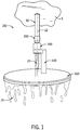
- the flow device 300 is configured to produce a stream of fluid having a substantially laminar flow, shown as fluid stream 20 (see FIG. 1 ). As shown in FIG. 2 , the fluid stream 20 is produced over a first coverage area 24. The fluid stream 20, extending between the flow device 300 and the distribution plate 500, is visible to a user or occupant of the shower (see FIG. 1 ).
- the support post 400 is disposed between the flow device 300 and the distribution plate 500 and is configured to carry the full weight of the distribution plate 500.
- a first end 402 of the support post 400 is rotatably coupled to the flow device 300 via an extension piece 404.
- the extension piece 404 extends radially outward from a primary axis 406 of the support post 400 such that the support post 400 is clear of the fluid stream 20 (i.e., the support post 400 does not disrupt the fluid stream 20 at any position along the fluid stream 20).
- the support post 400 is oriented in a direction that is substantially parallel to the fluid stream 20.
- a second end 408 of the support post 400 is coupled to the distribution plate 500 proximate to a central axis 506 of the distribution plate 500.
- the distribution plate 500 is configured to produce a flow of water characterized by a second flow arrangement, shown as distributed fluid flow 30 (see FIGS. 1-2 ).
- the distribution plate 500 includes a base, shown as wall 502, configured to receive the fluid stream 20 produced by the flow device 300.
- the wall 502 is oriented normal to a primary axis 22 of the fluid stream 20.
- the wall 502 is configured to receive the fluid stream 20 on an upper surface 504 of the wall 502.
- the fluid stream 20 contacts the wall 502 at a central position along an upper surface 504 proximate to a central axis 506 of the distribution plate 500 (see also FIG. 5 ).
- Water received by the upper surface 504 is distributed by gravity radially along the upper surface 504 toward an outer perimeter of the wall 502. Water falls from (i.e., separates from) the outer perimeter of the wall 502 as the distributed fluid flow 30.
- the distributed fluid flow 30 is configured in a waterfall pattern that surrounds a second coverage area 31 (see FIG. 2 ), along an outer perimeter of the second coverage area 31, with water.
- the flow pattern generated by the distributed fluid flow 30 along with other flow characteristics of the distributed fluid flow 30 may be different.
- the showerhead connector 200 is made from a single piece of material such as brass, stainless-steel, or another corrosion resistant material.
- the showerhead connector 200 includes a first connecting end 202 and a second connecting end 204.
- the first connecting end 202 is configured to be coupled to a water source (e.g., a water supply line, etc.).
- a water source e.g., a water supply line, etc.
- the first connecting end 202 includes a threaded interface that removably couples the showerhead connector 200 to the water source, although in alternative embodiments any suitable water-tight connection mechanism may be used.
- the second connecting end 204 of the showerhead connector 200 includes a pivot member 206. As shown in FIGS. 5-6 , the pivot member 206 is configured as a smooth spherical surface (i.e., ball joint) configured to engage with the flow device 300.
- the showerhead connector 200 additionally includes an opening, shown as connector opening 207, extending along a primary axis 208 of the showerhead connector 200.
- the connector opening 207 fluidly couples the first connecting end 202 with the second connecting end 204.
- the showerhead connector 200 further includes a flow regulator disposed within the connector opening 207 and configured to control the flow rate of water through the connector 200.
- the flow device 300 includes a body 302 including an outer body portion 304 and an inner body portion 306.
- the outer body portion 304 is a cylindrical sleeve made from a single piece of material.
- the outer body portion 304 is a metal sleeve stamped or otherwise formed from brass, stainless steel, or another corrosion resistant material.
- the outer body portion 304 is configured to receive the second connecting end 204 of the showerhead connector 200 and an upper end of the inner body portion 306. As shown in FIG. 6 , the outer body portion 304 fits over the first connecting end 202 of the showerhead connector 200 and is coupled against the smooth spherical surface of the pivot member 206 for the showerhead connector 200.
- the flow device 300 is pivotably coupled to the second connecting end 204 of the showerhead connector 200.
- the flow device 300 includes an upper bearing 308 and a lower bearing 310 disposed in an inner cavity of the outer body portion 304.
- the upper bearing 308 and the lower bearing 310 are each formed from a single piece of material (e.g., plastic or another suitable polymer) and are slidably coupled to the pivot member 206.
- the pivot member 206 is sandwiched between the upper bearing 308 and the lower bearing 310.
- the lower bearing 310 is secured in position by the inner body portion 306.
- the inner body portion 306 is a cylindrical sleeve made from a single piece of material.
- the inner body portion 306 is a metal sleeve stamped or otherwise formed from brass, stainless steel, or another corrosion resistant material.
- the inner body portion 306 engages with the outer body portion 304 and is secured in position relative to the outer body portion 304.
- the inner body portion 306 includes a threaded interface that engages with the outer body portion 304 along an inner surface of the outer body portion 304.
- An interface surface 312 of the inner body portion 306 presses against the lower bearing 310.
- the force applied to the lower bearing 310 by the inner body portion 306 results in a contact pressure between the bearings 308, 310 and the pivot member 206.
- the contact pressure may be adjusted by rotating the inner body portion 306 relative to the outer body portion 304.
- the contact pressure between the bearings 308, 310 and the pivot member 206 is adjusted to allow the flow device 300 to freely pivot relative to the showerhead connector 200.
- this allows a user to adjust a discharge angle of the fluid stream 20 (see also FIG. 1 ) relative to the primary axis 208 of the showerhead connector 200.
- the flow device 300 includes an aerator 314 configured to produce a fluid stream characterized by a laminar flow arrangement.
- the aerator 314 may be one of a variety of different laminar flow attachments.
- the aerator 314 may be an aerator insert such as a Neoperl® aerator.
- the aerator 314 may be flow-regulated to meter the flow rate and to ensure that the flow produced by the aerator 314 is laminar.
- the aerator 314 is removably coupled to the inner body portion 306. The aerator 314 used in the embodiment of FIGS.
- the aerator 314 is permanently coupled to the inner body portion 306 (e.g., glued to the inner body portion 306, welded to the inner body portion 306, or integrally formed with the inner body portion 306 as a single unitary structure). As shown in FIG. 6 , the aerator 314 is recessed into an outer surface of the inner body portion 306, which improves the aesthetic appearance of the showerhead 100.
- the flow device 300 is configured to produce a substantially laminar flow arrangement, shown as fluid stream 20 (see also FIG. 1 ) over a first coverage area 24 (see FIG. 2 ), the diameter of which is approximately equal to the diameter of the aerator 314.
- the aerator 314 is configured to produce a cylindrical stream of fluid, which is ejected from the aerator 314 and out through an aperture in the inner body portion 306.
- the geometry of the fluid stream 20 may be different.
- the flow device 300 may include multiple aerators 314 to improve the distribution of flow on the distribution plate 500 or to improve the aesthetic appearance of the showerhead 100.
- the aerators 314 may be arranged side-by-side, staggered vertically, or configured in another arrangement depending on functional requirements and user preference.
- the showerhead 100 includes a plurality of sealing members to prevent water from bypassing the aerator 314.
- the showerhead 100 includes an O-ring positioned in an annular space between the inner body portion 306 and the outer body portion 304, outboard of the threaded interface for the inner body portion.
- the O-ring is disposed within a circumferential groove on an outer radial surface of the inner body portion 306.
- Another O-ring is included outboard of the threaded interface for the aerator 314 (i.e., between the aerator 314 and the inner body portion 306 on an outer radial surface of the aerator 314).
- a third O-ring may be included inboard of the threaded interface for the aerator 314. In other embodiments, more or fewer O-rings and/or other sealing members may be included.
- the support post 400 for the showerhead 100 is configured to couple one or a combination of the water source, the showerhead connector 200, and/or the flow device 300 to the distribution plate 500. As shown in FIGS. 5-6 , the support post 400 is configured to couple the flow device 300 to the distribution plate 500.
- the support post 400 includes a first end 402 and a second end 408 disposed opposite the first end 402. A distance between the flow device 300 and the distribution plate 500 is determined by a length of the support post 400 (e.g., a vertical length of the support post, a length of the support post 400 parallel to the primary axis 406 of the support post 400, etc.). In the embodiment of FIGS.
- the distance between the flow device 300 and the support post i.e., a distance between the aerator 314 outlet and an upper surface 504 of the distribution plate 500
- the distance between the flow device 300 and the support post may be different depending on flow rate.
- the support post 400 includes an extension piece 404 disposed on the first end 402 extending radially outward from a primary axis 406 of the support post 400.
- the extension piece 404 may be formed separately from the support post 400 or along with the support post 400 as a single body.
- the extension piece 404 is rotatably coupled to the flow device 300 to allow a user to reposition the support post 400 relative to the fluid stream 20.
- the extension piece 404 is configured as a cylindrical sleeve whose inner diameter is slightly larger than an outer diameter of the inner body portion 306.
- this connection mechanism allows the support post 400 to rotate a full 360° about the inner body portion 306 (and the fluid stream 20 as shown in FIG. 1 ).
- the extension piece 404 fits over the inner body portion 306 and is secured in position between the outer body portion 304 and a circumferential step extending from an outer radial surface of the inner body portion 306 (e.g., a step or circumferential protrusion whose outer diameter is greater than the inner diameter of the extension piece 404).
- a washer may be disposed in an axial gap formed between the extension piece 404 and one or a combination of the inner body portion 306 and outer body portion 304 to reduce friction between the components.
- the showerhead 100 includes two low-friction plastic washers configured to facilitate movement of the support post 400 relative to the inner body portion 306.
- a first washer 405 is received within an axial gap formed between a lower surface of the extension piece 404 and the inner body portion 306, and a second washer 407 is received within an axial gap formed between an upper surface of the extension piece 404 and the outer body portion 304.
- the showerhead 100 additionally includes two O-rings 409 in an annular gap between the extension piece 404 and the outer radial surface of the inner body portion 306.
- Each of the O-rings 409 is disposed within a circumferential groove on the outer radial surface of the inner body portion 306, which retains the O-rings 409 during normal operation.
- the O-rings 409 help prevent fluid ingestion into the annular gap between the outer radial surface of the inner body portion and the extension piece 404, which prevents corrosion and reduces friction.
- the second end 408 of the support post 400 is coupled to the distribution plate 500.
- the support post 400 is a hollow tube.
- the geometry of the support post 400 may vary depending on the flow requirements and user preferences.
- the support post 400 is shaped as an elongated cylinder.
- the support post 400 may take the shape of a rectangular cuboid or another shape having identical cross-sections normal to its primary axis 406.
- the support post 400 is curved away from the flow device 300.
- the second end 408 of the support post 400 is configured to receive a connecting flange, shown as flange 508, of the distribution plate 500.
- An inner diameter of the support post 400 is slightly larger than an outer diameter of the flange 508.
- the support post 400 includes a circumferential step 410 that extends inward toward the primary axis 406 from an outer wall 412 of the support post 400.
- the circumferential step 410 engages with a fastener 414 (e.g., a bolt, screw, or another suitable fastener) that couples the support post 400 to the distribution plate 500.
- the fastener 414 is received by the support post 400 through the first end 402 of the support post 400 (i.e., a top of the support post 400).
- a head of the bolt engages with a top surface of the circumferential step 410, while a threaded portion of the fastener 414 engages with a threaded interface in the flange 508.
- the fastener 414 used to secure the support post 400 to the distribution plate 500 is not visible to a user (e.g., is hidden within the hollow portion of the support post 400), which improves the aesthetic appeal of the showerhead 100.
- the circumferential step 410 is positioned within the support post 400 at a sufficient depth to allow the flange 508 to be received completely within the support post 400 (i.e., to be received within the support post 400 such that the flange 508 is completely surrounded by the outer wall 412).
- the showerhead 100 additionally includes a plug, shown as end cap 416, configured to block off an opening in the first end 402 of the support post 400.
- the end cap 416 includes an O-ring disposed within a circumferential groove on an outer radial surface of the end cap 416. The O-ring is configured to seal against the inner surface of the outer wall 412 and thereby prevent moisture from entering and corroding the support post 400 and/or the fastener 414.
- the end cap 416 is countersunk into the first end 402 of the support post 400 to improve the aesthetic appearance of the support post 400.
- the distribution plate 500 includes a base, shown as wall 502, defining a substantially planar surface oriented substantially normal to the primary axis 22 of the fluid stream 20 (also see FIG. 1 ), such that the planar surface faces an outlet of the flow device 300.
- the distribution plate 500 also includes a ledge or lip 510 disposed along a perimeter of the wall 502.
- the distribution plate 500 may be stamped or otherwise formed from a single piece of material (e.g., brass, stainless steel, or another corrosion resistant material).
- the flange 508 is coupled to the distribution plate 500 at a central position along the upper surface 504 of the wall 502.
- the flange 508 may be welded to the wall 502 or integrally formed with the distribution plate 500 as a single unitary structure (e.g., via a machining operation, injection molding, etc.).
- incorporating the flange 508 at a central position along the upper surface 504 allows radial space for the flow to redistribute around the support post 400 and along the wall 502 before falling from the distribution plate 500.
- the wall 502 and the lip 510 define a hollow cavity 512 (e.g., hollow portion) forming a cup-shape.
- the lip 510 extends downward and away from the wall 502 (i.e., an upside down cup).
- the lip 510 extends downward from the wall 502 in a direction that is substantially perpendicular to the wall 502.
- an angle is formed between an upper surface of the lip 510 and an upper surface 504 of the wall 502 where the lip 510 contacts the wall 502.
- the distribution plate 500 is formed without a lip 510 (e.g., as a flat plate).
- the distribution plate 500 may be configured in a variety of different geometries depending on flow requirements (e.g., water flow rate and flow intensity) and user preferences.
- the distribution plate 500 is configured as a circular plate having a diameter of about 12 in (30.5 cm).
- the distribution plate 500 is configured to provide a distributed fluid flow 30 at flow rates within a range between about 1.75 gpm (6.6 L/min water) and about 3.5 gpm (13.2 L/min).
- the distribution plate 500 may be rectangular or have both straight and curved edges.
- Various other geometries for the distribution plate are possible.
- the distribution plate 500 produces a distributed fluid flow 30 (see also FIG. 1 ) over a second coverage area 31 (see FIG. 2 ).
- the distribution plate 500 is configured to receive the fluid stream 20 on the upper surface 504 of the wall 502. As shown in FIG. 1 , both the fluid stream 20 and the distributed fluid flow 30 are exposed to the atmosphere (e.g., to an environment surrounding the showerhead, etc.) such that they may be viewed by a user of the shower. In other words, the fluid stream 20 and the distributed fluid flow 30 are not contained within or concealed by any components of the showerhead 100.
- the flow distributes along a radial extent of the upper surface 504 and toward the lip 510. The flow separates from (i.e.
- the flow may separate from the outer perimeter of the lip 510 in sheets and/or droplets, simulating the flow of a waterfall. Water is pulled by the force of gravity from the showerhead 100 toward a user, which allows the showerhead 100 to be used across a wide range of flow rates.
- the second coverage area 31 (see FIG. 2 ) for the distributed fluid flow 30 is greater than the first coverage area 24 (see FIG. 2 ) and is approximately equal to an area enclosed by the outer perimeter of the lip 510.
- the waterfall flow pattern provided by the distribution plate 500 provides a dry core region that is shielded by the wall 502.
- a user's head may be positioned within this region, immediately below the wall 502, and remain dry, while the rest of the user's body is covered or partially covered in fluid from the distributed fluid flow 30.
- FIG. 7 shows a showerhead for a shower configured to produce a distributed fluid flow 32 in a rainfall pattern, according to an exemplary embodiment.
- a similar showerhead, shown as showerhead 1000 is illustrated conceptually in FIGS. 8-10 .
- the showerhead 1000 includes a showerhead connector, shown as connector 1200, a flow device 1300, a support member, shown as support post 1400, and a flow distribution member, shown as distribution plate 1500.
- Each of the connector 1200, flow device 1300, and support post 1400 may be substantially similar to that shown in the embodiment of FIGS. 2-6 .
- the distribution plate 1500 of FIGS. 8-10 includes a base, shown as wall 1502, and a ledge or lip 1510 disposed on the wall 1502 along a perimeter of the wall 1502.
- the wall 1502 defines a substantially planar surface.
- the lip 1510 extends upward from the outer perimeter of the wall 1502 such that an outer surface of the lip 1510 is substantially perpendicular to an upper surface 1504 of the wall 1502.
- the wall 1502 and the lip 1510 define a hollow cavity (i.e., a hollow cavity forming an upward facing cup shape) within which the fluid stream 20 is received.
- the distribution plate 1500 includes a plurality of perforations 1514 (e.g., openings, holes, nozzles, etc.) disposed in the wall 1502 and configured to dispense water as a distributed fluid flow 32 (see also FIG. 7 ).
- the fluid is pulled through the perforations 1514 by the force of gravity.
- the fluid separates from a lower surface of the wall 1502 in droplets simulating a rainfall pattern.
- the wetted surfaces of the distribution plate 1500 of FIGS. 8-10 are completely or substantially open to the atmosphere, thereby allowing water to drain quickly and completely after use. Any water remaining on the distribution plate 1500 after the flow of water has been terminated is allowed to evaporate freely to the surroundings.
- the size, number, shape, and arrangement of perforations in the flow distribution plate 1500 may vary depending on the flow requirements for the showerhead 1000 and user preferences.
- a total of about 91 circular holes are disposed in the plate 1500.
- the holes are distributed in concentric rows on the wall 1502, each row including a plurality of holes in a substantially circular pattern (e.g., a bullseye configuration, etc.).
- a diameter of the holes may also vary depending on the required flow rate of fluid (and multiple different hole diameters may be used in a single showerhead to provide droplets of different sizes to the user).
- the diameter of each hole may be any size within a range substantially between about 0.12 in and 0.14 in.
- a height of the lip 1510 (e.g., a distance between an upper edge of the lip 1510 and the upper surface 1504 of the wall 1502) for the distribution plate 1500 may also vary.
- the height of the lip 1510 may be small to prevent any water from falling from the edge of the wall 1502.
- the height of the lip 1510 may be large to allow a quantity of water to pool within the hollow cavity of the distribution plate 1500.
- a second coverage area 34 (see FIG. 8 ) for the distributed fluid flow 32 is approximately equal to an area outlined by the outermost holes, which are proximate to an outer edge of the wall 1502 of the distribution plate 1500.
- the geometry of the distribution plate may vary depending on the desired coverage area (e.g., second coverage area 34) of the distributed fluid flow 32.
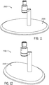
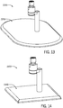
- FIGS. 11-14 show distribution plates 2050, 2150, 2250, 2350 for showerheads 2000, 2100, 2200, 2300 of a variety of different shapes and sizes, including oval ( FIGS. 11-12 ), oval with straight and rounded edges ( FIGS. 13 ), and rectangular ( FIG. 14).
- FIG. 13 shows a substantially oval plate 2250 for a showerhead 2200 having a lengthwise dimension 2251 of approximately 14 in.
- FIG. 14 shows a square plate whose edges measure approximately 8 in. (20.3) in length.
- the showerheads of FIGS. 11-14 are configured to produce a distributed fluid flow 30 in a waterfall pattern (see FIG. 1 ). Similar geometries for the distribution plates 2050, 2150, 2250, 2350 could also be used for a showerhead configured to produce a distributed fluid flow 32 in a rainfall pattern (see FIG. 7 ).
- FIG. 15 Another embodiment of a showerhead 3000 is shown in FIG. 15 .
- the showerhead 3000 includes a flow device 3300 that is fixably coupled to a showerhead connector 3200.
- a support member 3400 for the showerhead 3000 includes a plurality of posts, which rotatably couple a distribution plate 3500 to the flow device 3300 and/or showerhead connector 3200 such that the distribution plate 3500 may rotate freely around a primary axis 3208 of the showerhead connector 3200.
- Each of the posts includes a horizontal portion that extends outward from the primary axis 3208 of the showerhead connector 3200 (e.g., radially outward relative to the primary axis 3208), a bent portion (e.g., a 90° bend, etc.) that extends from the horizontal portion, and a vertical portion that extends from the bent portion to an upper surface 3504 of a wall 3502 of the distribution plate 3500.
- a bent portion e.g., a 90° bend, etc.
- FIG. 16 Yet another embodiment of a showerhead 4000 is shown in FIG. 16 .
- the showerhead 4000 includes a flow device 4300 pivotably coupled to a showerhead connector 4200.
- the flow device 4300 is configured to produce a fluid stream 20 (see also FIG. 1 ) at a central position above a distribution plate 4500.
- the support member 4400 is configured to completely wrap around an outer edge of the distribution plate 4500 and connect with the distribution plate 4500 proximate to a central position (e.g., aligned with a primary axis 22 of the fluid stream 20) on a lower surface of the distribution plate 4500.
- a central position e.g., aligned with a primary axis 22 of the fluid stream 20
- the waterfall pattern of fluid produced by the showerhead 4000 of FIG. 16 may be partially blocked by the support member 4400 where the support member 4400 wraps around the outer edge of the distribution plate 4500.
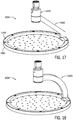
- FIG. 17 Yet another embodiment of a showerhead 5000 is shown in FIG. 17 .
- the showerhead 5000 is configured to produce a distributed fluid flow 32 in a rainfall pattern.
- the showerhead 5000 includes a support member 5400 that extends at an angle (i.e., an angle relative to a primary axis 22 of a fluid stream 20) between a flow device 5300 and a distribution plate 5500. More specifically, the support member 5400 extends from a central position above the distribution plate 5500 to a lip 5510 of the distribution plate 5500 proximate to an outer perimeter of the distribution plate 5500.
- a similar showerhead 6000 configuration is shown in FIG. 18 , although with a curved support post 6400 rather than a support post that extends linearly between the flow device and the lip.
- a showerhead 6000 is shown to include a support post 6400 that is integrally formed with a body 6302 of a flow device 6300.
- the support post 6400 is integrally formed with an outer body portion 6304 of the body 6302.
- the support post 6400 includes an angled body portion 6401 a retaining ring 6403 that is welded to a lower end of the angled body portion 6401.
- the retaining ring 6403 may be secured to the angled body portion 6401 via a fastener or integrally formed with the angled body portion 6401 as a single unitary structure.
- the retaining ring 6403 is disposed along a perimeter of a distribution plate 6500 of the showerhead 6000, inboard of a lip 6510 of the distribution plate 6500.
- the support post 6400 is coupled to a distribution plate 6500 via an intermediate ring 6501, which is "sandwiched" or otherwise disposed between the retaining ring 6403 and an upper surface of the distribution plate 6500.
- the distribution plate further includes a plurality of internally threaded posts 6511 that extend upwardly from the upper surface in substantially perpendicular orientation relative to the upper surface.
- Both the retaining ring 6403 and the intermediate ring 6501 are secured in position with respect to the distribution plate 6500 by a plurality of fasteners (e.g., screws, bolts, etc.) that engage with the posts 6511 on the distribution plate 6500.
- a plurality of fasteners e.g., screws, bolts, etc.
- the showerhead may include lighting elements to improve the overall aesthetic of the showerhead.
- the lighting elements may be configured to project onto the surface of the water above the distribution plate and to reflect off the distribution plate and onto a ceiling above the showerhead or to other walls of a shower enclosure.
- FIGS. 22-25 different lighting concepts for a showerhead are shown, according to various exemplary embodiments.
- FIG. 22 shows a showerhead 7000 that includes a lighting element 7002 on an upper surface 7004 of a distribution plate 7006 for the showerhead 7000.
- the lighting element 7002 is a ring that is configured to be at least partially submersed in water.
- FIG. 23 shows a showerhead 7020 that includes a lighting element 7022 on a lower angled surface of a support post 7024 of the showerhead 7020.
- the lighting element 7022 of FIG. 23 is arranged to direct light downward onto a surface of the fluid volume retained within a cup-shaped distribution plate 7025.
- An upper surface 7026 of the distribution plate 7025 may include a reflective material such as chrome to redirect light toward a ceiling above the showerhead and thereby provide a relaxing aesthetic for an occupant of the shower.
- FIG. 24 shows a showerhead 7040 that includes a lighting element 7042 disposed on a lower surface of a flow device 7044 of the showerhead 7040.
- the lighting element 7042 is in a ring shape and extends along a perimeter of the lower surface around the laminar flow stream to direct into the laminar flow stream and downward onto the water/distribution plate.
- FIG. 25 shows a showerhead 7060 that includes a lighting element 7062 disposed centrally on a lower surface of a flow device 7064 of the showerhead 7060. During operation, fluid flowing out through the lower surface surrounds the lighting element 7042, which may further enhance the overall aesthetic (due to light penetrating radially outwardly through the laminar flow stream.
- the lighting element 7062 may include a light emitting diode (LED) or another compact or low profile light source.
- FIG. 26 shows a showerhead 7080 that includes lighting elements 7082 disposed along an outer perimeter of a distribution plate 7084.
- the lighting elements 7082 direct light inwardly (e.g., radially inwardly) toward a central axis of the distribution plate 7084.
- the lighting elements 7082 are coupled to a retaining ring 7086 of a support post 7088 for the showerhead 7080 and are configured to be at least partially submerged beneath a volume of water that is contained within a hollow cavity of the cup-shaped distribution plate 7084.
- the lighting elements may be electrically coupled to hydrogenerator built into the showerhead 7080 or another standalone power source built into the showerhead 7080.
- FIG. 27 shows a showerhead 8000 that includes a lighting element 8002 and a power source 8004 electrically coupled to the lighting element 8002.
- the lighting element 8002 is coupled to an angled lower surface of a support post 8006 of the showerhead 8000 so as to direct light downwardly at an angle toward an upper surface of a distribution plate 8008.
- the lighting element 8002 is electrically coupled to the power source 8004 via wires that extend at least partially through a hollow portion 8010 of the support post 8006.
- the power source 8004 is coupled to an upper end of the support post 8006.
- the power source 8004 is "sandwiched" or otherwise disposed between a showerhead connector 8012 and the inner body portion 8014 of a flow device 8016.
- the power source 8004 is a water-driven turbine that generates power in proportion to a flow rate of water through the flow device 8016 (e.g., a flow of water passing through the showerhead 8000).
- the turbine may be configured to power the lighting element 8002 whenever water is provided to the showerhead 8000 and at an intensity that is proportional to the flow rate of water.
- the lighting element 8002 may be configured such that the intensity of light is approximately constant regardless of the flow rate.
- the showerhead may include a switch to enable or disable the lighting element 8002 based on user preferences.
- the showerhead 8000 may include a power storage device (e.g., a battery) that may be used to power the lighting element 8002 for a period of time when the flow of water to the showerhead 8000 is terminated.
- the showerhead of which various exemplary embodiments are disclosed herein, provides several advantages over conventional showerhead fixtures.
- the showerhead produces a fluid stream 20 and a distributed fluid flow 30, 32, both of which are visible to a user or occupant of a shower.
- These flow arrangements can, advantageously, provide for a more relaxing shower experience and a more pleasing aesthetic to a user or occupant of the shower.
- the showerheads disclosed herein have a more efficient structural design that can help to limit water flow restrictions and the accumulation of bacteria.
- the showerhead may include a lighting element and standalone power source to illuminate different portions of the showerhead during operation to thereby provide a relaxing aesthetic to an occupant of the shower.
- Coupled means the joining of two members directly or indirectly to one another. Such joining may be stationary (e.g., permanent) or moveable (e.g., removable or releasable). Such joining may be achieved with the two members or the two members and any additional intermediate members being integrally formed as a single unitary body with one another or with the two members or the two members and any additional intermediate members being attached to one another.
- An aspect provides a showerhead, comprising: a flow device configured to produce a substantially laminar fluid stream; and a flow distribution member coupled to the flow device and spaced apart from the flow device, the flow distribution member configured to receive the substantially laminar fluid stream and to produce a distributed fluid flow.
- the showerhead may further comprise a showerhead connector pivotably coupled to the flow device and configured to fluidly couple the showerhead to a water source within a shower enclosure.
- the showerhead may further comprise a support member, wherein a first end of the support member is coupled to the flow device, and wherein a second end of the support member is coupled to the flow distribution member, and wherein the substantially laminar fluid stream is visible to a user when water is flowing through the showerhead.
- the support member may be rotatably coupled to the flow device.
- the flow device may be configured to produce the substantially laminar fluid stream over a first coverage area, and the flow distribution member may be configured to produce the distributed fluid flow over a second coverage area that is larger than the first coverage area.
- the flow distribution member may comprise a base defining a substantially planar surface that faces an outlet of the flow device, wherein the substantially planar surface is open to the surrounding atmosphere.
- the flow distribution member may further comprise a lip disposed along a perimeter of the base, wherein together the base and the lip define a hollow cavity forming a cup-shape.
- the lip may extend downwardly from the base away from the flow device in a substantially perpendicular orientation relative to the base.
- the lip may extend upwardly from the base toward the flow device in a substantially perpendicular orientation relative to the base, and the base may comprise a plurality of perforations.
- the showerhead may comprise a lighting element coupled to at least one of the flow device or the flow distribution member, wherein the lighting element directs light at least partially toward the flow distribution member.
- the showerhead may comprise a power source coupled to the flow device and electrically coupled to the lighting element.
- the power source may be a water-driven turbine.
- a showerhead comprising:
- the showerhead connector may be pivotably coupled to the showerhead connector, wherein the showerhead connector may be configured to fluidly couple the showerhead to a water source within a shower enclosure.
- the flow device may be configured to produce the substantially laminar fluid stream over a first coverage area, and the flow distribution member may be configured to produce the distributed fluid flow over a second coverage area that is larger than the first coverage area.
- the substantially laminar fluid stream may be visible to a user when water is flowing through the showerhead.
- the flow distribution member may comprise a base defining a substantially planar surface that faces an outlet of the flow device, wherein the substantially planar surface is open to the surrounding atmosphere.
- the flow distribution member may comprise a lip disposed along a perimeter of the base, wherein together the base and the lip define a hollow cavity forming a cup-shape.
- the lip may extend downwardly from the base away from the flow device in a substantially perpendicular orientation relative to the base.
- the lip may extend upwardly from the base toward the flow device in a substantially perpendicular orientation relative to the base, and the base may comprise a plurality of perforations.
- the showerhead may comprise a lighting element coupled to at least one of the support member, the flow device, or the flow distribution member, wherein the lighting element directs light at least partially toward the flow distribution member.
- the showerhead may comprise a power source, e.g. a water-driven turbine, coupled to the flow device and electrically coupled to the lighting element.
- a power source e.g. a water-driven turbine
Landscapes
- Physics & Mathematics (AREA)
- Fluid Mechanics (AREA)
- Nozzles (AREA)
Abstract
Description
- This application claims the benefit of and priority to
U.S. Provisional Patent Application No. 62/721,332, filed August 22, 2018 - The present application relates generally to the field of showers. More specifically, the present application relates to a showerhead.
- Generally speaking, a showerhead can dispense water from above a user-occupied space within a shower. The showerhead can be connected to a water source via a household water supply line extending from a side wall or an upper wall of a fixed structure, such as a building or a shower enclosure. The showerhead can produce a spray of water to facilitate cleaning operations and/or to enhance user comfort by more fully covering the user in water. Conventional showerheads typically include internal components/mechanisms and nozzles that produce a water spray of varying patterns and intensities. The nozzles can also restrict the flow of water to minimize water consumption during a shower event.
- One exemplary embodiment relates to a showerhead. The showerhead includes a flow device and a flow distribution member. The flow device is configured to produce a substantially laminar fluid stream. The flow distribution member is coupled to the flow device and is spaced apart from the flow device. The flow distribution member is configured to receive the substantially laminar fluid stream from the flow device and to produce a distributed fluid flow.
- Another exemplary embodiment relates to a showerhead. The showerhead includes a showerhead connector, a support member, a flow device, and a flow distribution member. The flow device is coupled to the showerhead connector and is configured to produce a substantially laminar fluid stream. A first end of the support member is coupled to at least one of the showerhead connector, the support member, or the flow device. The flow distribution member is coupled to a second end of the support member and is configured to produce a distributed fluid flow.
- The disclosure will become more fully understood from the following detailed description, taken in conjunction with the accompanying figures, wherein like reference numerals refer to like elements, in which:
-
FIG. 1 is a top perspective view of a showerhead in operation in a shower, according to an exemplary embodiment. -
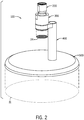
FIG. 2 is a top perspective view of the showerhead ofFIG. 1 , according to an exemplary embodiment. -
FIG. 3 is a bottom perspective view of the showerhead ofFIG. 2 . -
FIG. 4 is a front view of the showerhead ofFIG. 2 . -
FIG. 5 is an exploded perspective view of the showerhead ofFIG. 2 . -
FIG. 6 is a cross-sectional view of the showerhead ofFIG. 2 . -
FIG. 7 is a front view of a showerhead in operation in a shower, according to another exemplary embodiment. -
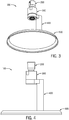
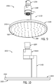
FIG. 8 is a top perspective view of a showerhead, according to another exemplary embodiment. -
FIG. 9 is a bottom perspective view of the showerhead ofFIG. 8 . -
FIG. 10 is a front view of the showerhead ofFIG. 8 . -
FIG. 11 is a top perspective view of a showerhead, according to another exemplary embodiment. -
FIG. 12 is a top perspective view of a showerhead, according to another exemplary embodiment. -
FIG. 13 is a top perspective view of a showerhead, according to another exemplary embodiment. -
FIG. 14 is a top perspective view of a showerhead, according to another exemplary embodiment. -
FIG. 15 is a top perspective view of a showerhead, according to another exemplary embodiment. -
FIG. 16 is a top perspective view of a showerhead, according to another exemplary embodiment. -
FIG. 17 is a top perspective view of a showerhead, according to another exemplary embodiment. -
FIG. 18 is a top perspective view of a showerhead, according to another exemplary embodiment. -
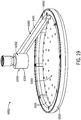
FIG. 19 is a top perspective view of a showerhead, according to another exemplary embodiment. -
FIG. 20 is a side cross-sectional view of the showerhead ofFIG. 19 . -
FIG. 21 is an exploded view of the showerhead ofFIG. 19 . -
FIG. 22 is a top perspective view of a showerhead, according to another exemplary embodiment. -
FIG. 23 is a top perspective view of a showerhead, according to another exemplary embodiment. -
FIG. 24 is a bottom perspective view of a showerhead, according to another exemplary embodiment. -
FIG. 25 is a bottom perspective view of a showerhead, according to another exemplary embodiment. -
FIG. 26 is a top perspective view of a showerhead, according to another exemplary embodiment. -
FIG. 27 is a perspective cross-sectional view of a showerhead, according to another exemplary embodiment. - Referring generally to the FIGURES, disclosed herein are various exemplary embodiments of a showerhead (e.g., water delivery device, flow distribution assembly, etc.). The showerhead is configured to be coupled to a water source through a water supply conduit within the shower. The showerhead is configured to produce two different flow arrangements (e.g., flow patterns, flow characteristics, flow structures, etc.), both of which are visible to a user or occupant of the shower. A first flow arrangement is a substantially laminar flow arrangement, while a second flow arrangement is a rainfall or waterfall flow arrangement that is distributed to a user. Among other benefits, the flow arrangements disclosed herein provide for a more relaxing shower experience and a more pleasing aesthetic to a user or occupant of the shower, as compared to conventional spray heads. In addition, the disclosed showerheads have a more efficient structural design that helps limit water flow restrictions and the accumulation of bacteria.
- According to an exemplary embodiment, the showerhead includes a showerhead connector, a flow device, a support member, and a flow distribution member. In some embodiments, the showerhead is configured as a retrofit showerhead assembly including a showerhead connector configured to fluidly couple the showerhead to a water source, such as through a household water supply conduit. The showerhead connector may include a pivoting member to allow a user to reposition the showerhead to modify flow characteristics or to provide an improved aesthetic appearance.
- The flow device is configured to produce a substantially laminar fluid stream over a first coverage area above the flow distribution member. The flow distribution member is configured to produce, from the substantially laminar fluid stream, a distributed fluid flow over a second coverage area. The second coverage area may be larger than the first coverage area to more fully cover a user with water. The distributed fluid flow may be provided in a waterfall or a rainfall flow configuration, pattern, or arrangement for an enhanced user experience. Advantageously, the distribution member is open to the atmosphere, which allows water to drain quickly and completely after each use, thereby limiting flow restrictions and the accumulation of bacteria. Furthermore, because the showerhead relies on gravity to produce the distributed fluid flow, the showerhead may be used across a wide range of flow rates.
- The flow distribution member is coupled by the support member to at least one of (one, or a combination of) the water source (e.g., the water supply conduit), the showerhead connector, or the flow device. The support member may be a hollow vertical post configured to receive a fastener and thereby conceal the fastener from a user's view. The fastener may be used to fixedly couple the support member to the flow distribution member. A first end of the support member may be rotatably coupled to the water source, the flow device, and/or the showerhead connector to allow a user to reposition the support member relative to the substantially laminar fluid stream.
- The flow distribution member may be a substantially planar surface or plate that faces the flow device. Water received on an upper surface of the plate is distributed radially outward toward an outer perimeter of the plate. The plate may include a lip disposed on the outer perimeter of the plate. The lip may be configured to distribute water in a waterfall pattern. A user positioned below the plate may be at least partially shielded from water by the plate, allowing the user to immerse their body with water while keeping their head dry. Alternatively, the plate may include a plurality of holes or perforations to distribute water from the plate in a rainfall pattern. These and other advantageous features will become apparent to those reviewing the present disclosure and figures.
- Referring to
FIGS. 1-4 , ashowerhead 100 is shown according to an exemplary embodiment. Theshowerhead 100 includes ashowerhead connector 200 fluidly coupled to a water source within ashower enclosure 5. In particular, theshowerhead connector 200 is removably coupled to a water supply conduit. In some embodiments, the water supply conduit is configured as a water pipe extending from an upper wall of theshower enclosure 5. In other embodiments, the water supply conduit is a pipe, tube, or other water delivery mechanism extending from a side wall of theshower enclosure 5. In the exemplary embodiment ofFIG. 1 , the water supply conduit is apipe 10 disposed centrally within the upper wall of theshower enclosure 5 and extending vertically downward from the upper wall. - As shown in
FIG. 5 , theshowerhead 100 includes aflow device 300, a support member (shown as support post 400), and a flow distribution member (shown as distribution plate 500). Theflow device 300 is pivotably coupled to theshowerhead connector 200 such that theflow device 300 may pivot at a connection point between theflow device 300 and the showerhead connector 200 (seeFIG. 4 ). In the embodiment ofFIGS. 1-4 , theflow device 300 extends vertically downward from theconnector 200. - The
flow device 300 is configured to produce a stream of fluid having a substantially laminar flow, shown as fluid stream 20 (seeFIG. 1 ). As shown inFIG. 2 , thefluid stream 20 is produced over afirst coverage area 24. Thefluid stream 20, extending between theflow device 300 and thedistribution plate 500, is visible to a user or occupant of the shower (seeFIG. 1 ). - The
support post 400 is disposed between theflow device 300 and thedistribution plate 500 and is configured to carry the full weight of thedistribution plate 500. As shown inFIG. 5 , afirst end 402 of thesupport post 400 is rotatably coupled to theflow device 300 via anextension piece 404. Theextension piece 404 extends radially outward from aprimary axis 406 of thesupport post 400 such that thesupport post 400 is clear of the fluid stream 20 (i.e., thesupport post 400 does not disrupt thefluid stream 20 at any position along the fluid stream 20). As shown inFIG. 1 , thesupport post 400 is oriented in a direction that is substantially parallel to thefluid stream 20. - As shown in
FIG. 5 , asecond end 408 of thesupport post 400 is coupled to thedistribution plate 500 proximate to acentral axis 506 of thedistribution plate 500. Thedistribution plate 500 is configured to produce a flow of water characterized by a second flow arrangement, shown as distributed fluid flow 30 (seeFIGS. 1-2 ). Thedistribution plate 500 includes a base, shown aswall 502, configured to receive thefluid stream 20 produced by theflow device 300. As shown inFIG. 1 , thewall 502 is oriented normal to aprimary axis 22 of thefluid stream 20. Thewall 502 is configured to receive thefluid stream 20 on anupper surface 504 of thewall 502. - The
fluid stream 20 contacts thewall 502 at a central position along anupper surface 504 proximate to acentral axis 506 of the distribution plate 500 (see alsoFIG. 5 ). Water received by theupper surface 504 is distributed by gravity radially along theupper surface 504 toward an outer perimeter of thewall 502. Water falls from (i.e., separates from) the outer perimeter of thewall 502 as the distributedfluid flow 30. In the embodiment ofFIG. 1 , the distributedfluid flow 30 is configured in a waterfall pattern that surrounds a second coverage area 31 (seeFIG. 2 ), along an outer perimeter of thesecond coverage area 31, with water. In various alternative embodiments, the flow pattern generated by the distributedfluid flow 30 along with other flow characteristics of the distributedfluid flow 30 may be different. - Referring again to
FIGS. 5-6 , theshowerhead connector 200 is made from a single piece of material such as brass, stainless-steel, or another corrosion resistant material. Theshowerhead connector 200 includes a first connectingend 202 and a secondconnecting end 204. The first connectingend 202 is configured to be coupled to a water source (e.g., a water supply line, etc.). As shown inFIG. 6 , the first connectingend 202 includes a threaded interface that removably couples theshowerhead connector 200 to the water source, although in alternative embodiments any suitable water-tight connection mechanism may be used. - The second
connecting end 204 of theshowerhead connector 200 includes apivot member 206. As shown inFIGS. 5-6 , thepivot member 206 is configured as a smooth spherical surface (i.e., ball joint) configured to engage with theflow device 300. Theshowerhead connector 200 additionally includes an opening, shown asconnector opening 207, extending along aprimary axis 208 of theshowerhead connector 200. Theconnector opening 207 fluidly couples the first connectingend 202 with the second connectingend 204. In other embodiments, theshowerhead connector 200 further includes a flow regulator disposed within theconnector opening 207 and configured to control the flow rate of water through theconnector 200. - As shown in
FIGS. 5-6 , theflow device 300 includes abody 302 including anouter body portion 304 and aninner body portion 306. Theouter body portion 304 is a cylindrical sleeve made from a single piece of material. In an exemplary embodiment, theouter body portion 304 is a metal sleeve stamped or otherwise formed from brass, stainless steel, or another corrosion resistant material. Theouter body portion 304 is configured to receive the second connectingend 204 of theshowerhead connector 200 and an upper end of theinner body portion 306. As shown inFIG. 6 , theouter body portion 304 fits over the first connectingend 202 of theshowerhead connector 200 and is coupled against the smooth spherical surface of thepivot member 206 for theshowerhead connector 200. - The
flow device 300 is pivotably coupled to the second connectingend 204 of theshowerhead connector 200. Theflow device 300 includes anupper bearing 308 and alower bearing 310 disposed in an inner cavity of theouter body portion 304. Theupper bearing 308 and thelower bearing 310 are each formed from a single piece of material (e.g., plastic or another suitable polymer) and are slidably coupled to thepivot member 206. As shown inFIG. 6 , thepivot member 206 is sandwiched between theupper bearing 308 and thelower bearing 310. Thelower bearing 310 is secured in position by theinner body portion 306. Similar to theouter body portion 304, theinner body portion 306 is a cylindrical sleeve made from a single piece of material. In an exemplary embodiment, theinner body portion 306 is a metal sleeve stamped or otherwise formed from brass, stainless steel, or another corrosion resistant material. Theinner body portion 306 engages with theouter body portion 304 and is secured in position relative to theouter body portion 304. In the embodiment ofFIGS. 5-6 , theinner body portion 306 includes a threaded interface that engages with theouter body portion 304 along an inner surface of theouter body portion 304. Aninterface surface 312 of theinner body portion 306 presses against thelower bearing 310. - The force applied to the
lower bearing 310 by theinner body portion 306 results in a contact pressure between thebearings pivot member 206. The contact pressure may be adjusted by rotating theinner body portion 306 relative to theouter body portion 304. In the exemplary embodiment ofFIG. 6 , the contact pressure between thebearings pivot member 206 is adjusted to allow theflow device 300 to freely pivot relative to theshowerhead connector 200. Among other benefits, this allows a user to adjust a discharge angle of the fluid stream 20 (see alsoFIG. 1 ) relative to theprimary axis 208 of theshowerhead connector 200. - The
flow device 300 includes anaerator 314 configured to produce a fluid stream characterized by a laminar flow arrangement. Theaerator 314 may be one of a variety of different laminar flow attachments. In some embodiments, theaerator 314 may be an aerator insert such as a Neoperl® aerator. Theaerator 314 may be flow-regulated to meter the flow rate and to ensure that the flow produced by theaerator 314 is laminar. In some embodiments, theaerator 314 is removably coupled to theinner body portion 306. Theaerator 314 used in the embodiment ofFIGS. 5-6 includes a threaded interface that engages with theinner body portion 306 along an inner surface of theinner body portion 306. The threaded configuration facilitates cleaning or replacement of theaerator 314 in the event of hard water buildup or other particulate obstruction. In alternative embodiments, theaerator 314 is permanently coupled to the inner body portion 306 (e.g., glued to theinner body portion 306, welded to theinner body portion 306, or integrally formed with theinner body portion 306 as a single unitary structure). As shown inFIG. 6 , theaerator 314 is recessed into an outer surface of theinner body portion 306, which improves the aesthetic appearance of theshowerhead 100. - The
flow device 300 is configured to produce a substantially laminar flow arrangement, shown as fluid stream 20 (see alsoFIG. 1 ) over a first coverage area 24 (seeFIG. 2 ), the diameter of which is approximately equal to the diameter of theaerator 314. In the embodiment ofFIGS. 5-6 , theaerator 314 is configured to produce a cylindrical stream of fluid, which is ejected from theaerator 314 and out through an aperture in theinner body portion 306. In other embodiments, the geometry of the fluid stream 20 (see alsoFIG. 1 ) may be different. In some embodiments, theflow device 300 may includemultiple aerators 314 to improve the distribution of flow on thedistribution plate 500 or to improve the aesthetic appearance of theshowerhead 100. Theaerators 314 may be arranged side-by-side, staggered vertically, or configured in another arrangement depending on functional requirements and user preference. - Among other assembly components, the
showerhead 100 includes a plurality of sealing members to prevent water from bypassing theaerator 314. As shown inFIGS. 5-6 , theshowerhead 100 includes an O-ring positioned in an annular space between theinner body portion 306 and theouter body portion 304, outboard of the threaded interface for the inner body portion. The O-ring is disposed within a circumferential groove on an outer radial surface of theinner body portion 306. Another O-ring is included outboard of the threaded interface for the aerator 314 (i.e., between the aerator 314 and theinner body portion 306 on an outer radial surface of the aerator 314). A third O-ring may be included inboard of the threaded interface for theaerator 314. In other embodiments, more or fewer O-rings and/or other sealing members may be included. - The
support post 400 for theshowerhead 100 is configured to couple one or a combination of the water source, theshowerhead connector 200, and/or theflow device 300 to thedistribution plate 500. As shown inFIGS. 5-6 , thesupport post 400 is configured to couple theflow device 300 to thedistribution plate 500. Thesupport post 400 includes afirst end 402 and asecond end 408 disposed opposite thefirst end 402. A distance between theflow device 300 and thedistribution plate 500 is determined by a length of the support post 400 (e.g., a vertical length of the support post, a length of thesupport post 400 parallel to theprimary axis 406 of thesupport post 400, etc.). In the embodiment ofFIGS. 5-6 , the distance between theflow device 300 and the support post (i.e., a distance between the aerator 314 outlet and anupper surface 504 of the distribution plate 500) is within a range between approximately 3 in (7.6 cm) and about 4 in (10.2 cm). In other embodiments, the distance between theflow device 300 and the support post may be different depending on flow rate. - The
support post 400 includes anextension piece 404 disposed on thefirst end 402 extending radially outward from aprimary axis 406 of thesupport post 400. Theextension piece 404 may be formed separately from thesupport post 400 or along with thesupport post 400 as a single body. Theextension piece 404 is rotatably coupled to theflow device 300 to allow a user to reposition thesupport post 400 relative to thefluid stream 20. As shown inFIG. 5 , theextension piece 404 is configured as a cylindrical sleeve whose inner diameter is slightly larger than an outer diameter of theinner body portion 306. Among other benefits, this connection mechanism allows thesupport post 400 to rotate a full 360° about the inner body portion 306 (and thefluid stream 20 as shown inFIG. 1 ). - The
extension piece 404 fits over theinner body portion 306 and is secured in position between theouter body portion 304 and a circumferential step extending from an outer radial surface of the inner body portion 306 (e.g., a step or circumferential protrusion whose outer diameter is greater than the inner diameter of the extension piece 404). A washer may be disposed in an axial gap formed between theextension piece 404 and one or a combination of theinner body portion 306 andouter body portion 304 to reduce friction between the components. As shown inFIGS. 5-6 , theshowerhead 100 includes two low-friction plastic washers configured to facilitate movement of thesupport post 400 relative to theinner body portion 306. Afirst washer 405 is received within an axial gap formed between a lower surface of theextension piece 404 and theinner body portion 306, and asecond washer 407 is received within an axial gap formed between an upper surface of theextension piece 404 and theouter body portion 304. - As shown in
FIGS. 5-6 , theshowerhead 100 additionally includes two O-rings 409 in an annular gap between theextension piece 404 and the outer radial surface of theinner body portion 306. Each of the O-rings 409 is disposed within a circumferential groove on the outer radial surface of theinner body portion 306, which retains the O-rings 409 during normal operation. Among other benefits, the O-rings 409 help prevent fluid ingestion into the annular gap between the outer radial surface of the inner body portion and theextension piece 404, which prevents corrosion and reduces friction. - The
second end 408 of thesupport post 400 is coupled to thedistribution plate 500. As shown inFIGS. 5-6 , thesupport post 400 is a hollow tube. The geometry of thesupport post 400 may vary depending on the flow requirements and user preferences. In the embodiment ofFIGS. 5-6 , thesupport post 400 is shaped as an elongated cylinder. In other embodiments, thesupport post 400 may take the shape of a rectangular cuboid or another shape having identical cross-sections normal to itsprimary axis 406. In yet other embodiments, thesupport post 400 is curved away from theflow device 300. - As shown in
FIGS. 5-6 , thesecond end 408 of thesupport post 400 is configured to receive a connecting flange, shown asflange 508, of thedistribution plate 500. An inner diameter of thesupport post 400 is slightly larger than an outer diameter of theflange 508. As shown inFIG. 6 , thesupport post 400 includes acircumferential step 410 that extends inward toward theprimary axis 406 from anouter wall 412 of thesupport post 400. Thecircumferential step 410 engages with a fastener 414 (e.g., a bolt, screw, or another suitable fastener) that couples thesupport post 400 to thedistribution plate 500. - As shown in
FIG. 6 , thefastener 414 is received by thesupport post 400 through thefirst end 402 of the support post 400 (i.e., a top of the support post 400). A head of the bolt engages with a top surface of thecircumferential step 410, while a threaded portion of thefastener 414 engages with a threaded interface in theflange 508. Advantageously, thefastener 414 used to secure thesupport post 400 to thedistribution plate 500 is not visible to a user (e.g., is hidden within the hollow portion of the support post 400), which improves the aesthetic appeal of theshowerhead 100. Thecircumferential step 410 is positioned within thesupport post 400 at a sufficient depth to allow theflange 508 to be received completely within the support post 400 (i.e., to be received within thesupport post 400 such that theflange 508 is completely surrounded by the outer wall 412). Theshowerhead 100 additionally includes a plug, shown asend cap 416, configured to block off an opening in thefirst end 402 of thesupport post 400. As shown inFIG. 6 , theend cap 416 includes an O-ring disposed within a circumferential groove on an outer radial surface of theend cap 416. The O-ring is configured to seal against the inner surface of theouter wall 412 and thereby prevent moisture from entering and corroding thesupport post 400 and/or thefastener 414. Theend cap 416 is countersunk into thefirst end 402 of thesupport post 400 to improve the aesthetic appearance of thesupport post 400. - Still referring to
FIGS. 5-6 , in an exemplary embodiment thedistribution plate 500 includes a base, shown aswall 502, defining a substantially planar surface oriented substantially normal to theprimary axis 22 of the fluid stream 20 (also seeFIG. 1 ), such that the planar surface faces an outlet of theflow device 300. Thedistribution plate 500 also includes a ledge orlip 510 disposed along a perimeter of thewall 502. Thedistribution plate 500 may be stamped or otherwise formed from a single piece of material (e.g., brass, stainless steel, or another corrosion resistant material). Theflange 508 is coupled to thedistribution plate 500 at a central position along theupper surface 504 of thewall 502. Theflange 508 may be welded to thewall 502 or integrally formed with thedistribution plate 500 as a single unitary structure (e.g., via a machining operation, injection molding, etc.). Advantageously, incorporating theflange 508 at a central position along theupper surface 504 allows radial space for the flow to redistribute around thesupport post 400 and along thewall 502 before falling from thedistribution plate 500. - Together, the
wall 502 and thelip 510 define a hollow cavity 512 (e.g., hollow portion) forming a cup-shape. As shown inFIG. 6 , thelip 510 extends downward and away from the wall 502 (i.e., an upside down cup). In some embodiments, thelip 510 extends downward from thewall 502 in a direction that is substantially perpendicular to thewall 502. In other embodiments, an angle is formed between an upper surface of thelip 510 and anupper surface 504 of thewall 502 where thelip 510 contacts thewall 502. In yet other embodiments, thedistribution plate 500 is formed without a lip 510 (e.g., as a flat plate). - The
distribution plate 500 may be configured in a variety of different geometries depending on flow requirements (e.g., water flow rate and flow intensity) and user preferences. In the embodiment ofFIGS. 5-6 , thedistribution plate 500 is configured as a circular plate having a diameter of about 12 in (30.5 cm). Thedistribution plate 500 is configured to provide a distributedfluid flow 30 at flow rates within a range between about 1.75 gpm (6.6 L/min water) and about 3.5 gpm (13.2 L/min). Alternatively, thedistribution plate 500 may be rectangular or have both straight and curved edges. Various other geometries for the distribution plate are possible. - The
distribution plate 500 produces a distributed fluid flow 30 (see alsoFIG. 1 ) over a second coverage area 31 (seeFIG. 2 ). Thedistribution plate 500 is configured to receive thefluid stream 20 on theupper surface 504 of thewall 502. As shown inFIG. 1 , both thefluid stream 20 and the distributedfluid flow 30 are exposed to the atmosphere (e.g., to an environment surrounding the showerhead, etc.) such that they may be viewed by a user of the shower. In other words, thefluid stream 20 and the distributedfluid flow 30 are not contained within or concealed by any components of theshowerhead 100. Once received on theupper surface 504 of thewall 502, the flow distributes along a radial extent of theupper surface 504 and toward thelip 510. The flow separates from (i.e. falls from) thelip 510 proximate to an outer perimeter of thelip 510. As shown inFIG. 1 , the flow may separate from the outer perimeter of thelip 510 in sheets and/or droplets, simulating the flow of a waterfall. Water is pulled by the force of gravity from theshowerhead 100 toward a user, which allows theshowerhead 100 to be used across a wide range of flow rates. The second coverage area 31 (seeFIG. 2 ) for the distributedfluid flow 30 is greater than the first coverage area 24 (seeFIG. 2 ) and is approximately equal to an area enclosed by the outer perimeter of thelip 510. - Among other benefits, the waterfall flow pattern provided by the
distribution plate 500 provides a dry core region that is shielded by thewall 502. A user's head may be positioned within this region, immediately below thewall 502, and remain dry, while the rest of the user's body is covered or partially covered in fluid from the distributedfluid flow 30. - Various other exemplary embodiments of the
showerhead 100 are possible without departing from the inventive concepts described herein. For example,FIG. 7 shows a showerhead for a shower configured to produce a distributedfluid flow 32 in a rainfall pattern, according to an exemplary embodiment. A similar showerhead, shown asshowerhead 1000, is illustrated conceptually inFIGS. 8-10 . Theshowerhead 1000 includes a showerhead connector, shown asconnector 1200, aflow device 1300, a support member, shown assupport post 1400, and a flow distribution member, shown asdistribution plate 1500. Each of theconnector 1200,flow device 1300, andsupport post 1400 may be substantially similar to that shown in the embodiment ofFIGS. 2-6 . - The
distribution plate 1500 ofFIGS. 8-10 includes a base, shown aswall 1502, and a ledge orlip 1510 disposed on thewall 1502 along a perimeter of thewall 1502. Thewall 1502 defines a substantially planar surface. Thelip 1510 extends upward from the outer perimeter of thewall 1502 such that an outer surface of thelip 1510 is substantially perpendicular to anupper surface 1504 of thewall 1502. Together, thewall 1502 and thelip 1510 define a hollow cavity (i.e., a hollow cavity forming an upward facing cup shape) within which thefluid stream 20 is received. Thedistribution plate 1500 includes a plurality of perforations 1514 (e.g., openings, holes, nozzles, etc.) disposed in thewall 1502 and configured to dispense water as a distributed fluid flow 32 (see alsoFIG. 7 ). The fluid is pulled through theperforations 1514 by the force of gravity. The fluid separates from a lower surface of thewall 1502 in droplets simulating a rainfall pattern. Similar to the embodiment ofFIGS. 2-6 , the wetted surfaces of thedistribution plate 1500 ofFIGS. 8-10 are completely or substantially open to the atmosphere, thereby allowing water to drain quickly and completely after use. Any water remaining on thedistribution plate 1500 after the flow of water has been terminated is allowed to evaporate freely to the surroundings. - The size, number, shape, and arrangement of perforations in the
flow distribution plate 1500 may vary depending on the flow requirements for theshowerhead 1000 and user preferences. In the embodiment ofFIGS. 8-10 , a total of about 91 circular holes are disposed in theplate 1500. The holes are distributed in concentric rows on thewall 1502, each row including a plurality of holes in a substantially circular pattern (e.g., a bullseye configuration, etc.). A diameter of the holes may also vary depending on the required flow rate of fluid (and multiple different hole diameters may be used in a single showerhead to provide droplets of different sizes to the user). In an exemplary embodiment, the diameter of each hole may be any size within a range substantially between about 0.12 in and 0.14 in. A height of the lip 1510 (e.g., a distance between an upper edge of thelip 1510 and theupper surface 1504 of the wall 1502) for thedistribution plate 1500 may also vary. In some embodiments, and particularly embodiments having a large open face area (i.e., a combined open area associated with all of the holes in the distribution plate 1500), the height of thelip 1510 may be small to prevent any water from falling from the edge of thewall 1502. In other embodiments, the height of thelip 1510 may be large to allow a quantity of water to pool within the hollow cavity of thedistribution plate 1500. - A second coverage area 34 (see
FIG. 8 ) for the distributedfluid flow 32 is approximately equal to an area outlined by the outermost holes, which are proximate to an outer edge of thewall 1502 of thedistribution plate 1500. The geometry of the distribution plate may vary depending on the desired coverage area (e.g., second coverage area 34) of the distributedfluid flow 32.FIGS. 11-14 show distribution plates showerheads FIGS. 11-12 ), oval with straight and rounded edges (FIGS. 13 ), and rectangular (FIG. 14). FIG. 13 shows a substantiallyoval plate 2250 for ashowerhead 2200 having a lengthwise dimension 2251 of approximately 14 in. (35.6 cm) and a width 2253 of approximately 8 in. (20.3 cm).FIG. 14 shows a square plate whose edges measure approximately 8 in. (20.3) in length. The showerheads ofFIGS. 11-14 are configured to produce a distributedfluid flow 30 in a waterfall pattern (seeFIG. 1 ). Similar geometries for thedistribution plates fluid flow 32 in a rainfall pattern (seeFIG. 7 ). - Another embodiment of a
showerhead 3000 is shown inFIG. 15 . Theshowerhead 3000 includes aflow device 3300 that is fixably coupled to ashowerhead connector 3200. Asupport member 3400 for theshowerhead 3000 includes a plurality of posts, which rotatably couple adistribution plate 3500 to theflow device 3300 and/orshowerhead connector 3200 such that thedistribution plate 3500 may rotate freely around aprimary axis 3208 of theshowerhead connector 3200. Each of the posts includes a horizontal portion that extends outward from theprimary axis 3208 of the showerhead connector 3200 (e.g., radially outward relative to the primary axis 3208), a bent portion (e.g., a 90° bend, etc.) that extends from the horizontal portion, and a vertical portion that extends from the bent portion to anupper surface 3504 of awall 3502 of thedistribution plate 3500. - Yet another embodiment of a
showerhead 4000 is shown inFIG. 16 . Theshowerhead 4000 includes aflow device 4300 pivotably coupled to ashowerhead connector 4200. Theflow device 4300 is configured to produce a fluid stream 20 (see alsoFIG. 1 ) at a central position above adistribution plate 4500. Thesupport member 4400 is configured to completely wrap around an outer edge of thedistribution plate 4500 and connect with thedistribution plate 4500 proximate to a central position (e.g., aligned with aprimary axis 22 of the fluid stream 20) on a lower surface of thedistribution plate 4500. Note that the waterfall pattern of fluid produced by theshowerhead 4000 ofFIG. 16 may be partially blocked by thesupport member 4400 where thesupport member 4400 wraps around the outer edge of thedistribution plate 4500. - Yet another embodiment of a
showerhead 5000 is shown inFIG. 17 . Theshowerhead 5000 is configured to produce a distributedfluid flow 32 in a rainfall pattern. Theshowerhead 5000 includes asupport member 5400 that extends at an angle (i.e., an angle relative to aprimary axis 22 of a fluid stream 20) between aflow device 5300 and adistribution plate 5500. More specifically, thesupport member 5400 extends from a central position above thedistribution plate 5500 to alip 5510 of thedistribution plate 5500 proximate to an outer perimeter of thedistribution plate 5500. Asimilar showerhead 6000 configuration is shown inFIG. 18 , although with acurved support post 6400 rather than a support post that extends linearly between the flow device and the lip. - Referring to
FIGS. 19-20 , ashowerhead 6000 is shown to include asupport post 6400 that is integrally formed with abody 6302 of aflow device 6300. In particular, thesupport post 6400 is integrally formed with anouter body portion 6304 of thebody 6302. Thesupport post 6400 includes an angled body portion 6401 aretaining ring 6403 that is welded to a lower end of theangled body portion 6401. In other embodiments, the retainingring 6403 may be secured to theangled body portion 6401 via a fastener or integrally formed with theangled body portion 6401 as a single unitary structure. The retainingring 6403 is disposed along a perimeter of adistribution plate 6500 of theshowerhead 6000, inboard of alip 6510 of thedistribution plate 6500. As shown inFIGS. 19-20 , thesupport post 6400 is coupled to adistribution plate 6500 via anintermediate ring 6501, which is "sandwiched" or otherwise disposed between the retainingring 6403 and an upper surface of thedistribution plate 6500. As shown inFIG. 21 , the distribution plate further includes a plurality of internally threadedposts 6511 that extend upwardly from the upper surface in substantially perpendicular orientation relative to the upper surface. Both theretaining ring 6403 and theintermediate ring 6501 are secured in position with respect to thedistribution plate 6500 by a plurality of fasteners (e.g., screws, bolts, etc.) that engage with theposts 6511 on thedistribution plate 6500. - In some embodiments, the showerhead may include lighting elements to improve the overall aesthetic of the showerhead. The lighting elements may be configured to project onto the surface of the water above the distribution plate and to reflect off the distribution plate and onto a ceiling above the showerhead or to other walls of a shower enclosure. Referring to
FIGS. 22-25 , different lighting concepts for a showerhead are shown, according to various exemplary embodiments.FIG. 22 shows ashowerhead 7000 that includes alighting element 7002 on anupper surface 7004 of adistribution plate 7006 for theshowerhead 7000. Thelighting element 7002 is a ring that is configured to be at least partially submersed in water.FIG. 23 shows ashowerhead 7020 that includes alighting element 7022 on a lower angled surface of asupport post 7024 of theshowerhead 7020. Thelighting element 7022 ofFIG. 23 is arranged to direct light downward onto a surface of the fluid volume retained within a cup-shapeddistribution plate 7025. Anupper surface 7026 of thedistribution plate 7025 may include a reflective material such as chrome to redirect light toward a ceiling above the showerhead and thereby provide a relaxing aesthetic for an occupant of the shower.FIG. 24 shows ashowerhead 7040 that includes alighting element 7042 disposed on a lower surface of aflow device 7044 of theshowerhead 7040. Thelighting element 7042 is in a ring shape and extends along a perimeter of the lower surface around the laminar flow stream to direct into the laminar flow stream and downward onto the water/distribution plate.FIG. 25 shows ashowerhead 7060 that includes alighting element 7062 disposed centrally on a lower surface of aflow device 7064 of theshowerhead 7060. During operation, fluid flowing out through the lower surface surrounds thelighting element 7042, which may further enhance the overall aesthetic (due to light penetrating radially outwardly through the laminar flow stream. In any of the above embodiments, thelighting element 7062 may include a light emitting diode (LED) or another compact or low profile light source. -
FIG. 26 shows ashowerhead 7080 that includeslighting elements 7082 disposed along an outer perimeter of adistribution plate 7084. Thelighting elements 7082 direct light inwardly (e.g., radially inwardly) toward a central axis of thedistribution plate 7084. Thelighting elements 7082 are coupled to aretaining ring 7086 of asupport post 7088 for theshowerhead 7080 and are configured to be at least partially submerged beneath a volume of water that is contained within a hollow cavity of the cup-shapeddistribution plate 7084. In some embodiments, the lighting elements may be electrically coupled to hydrogenerator built into theshowerhead 7080 or another standalone power source built into theshowerhead 7080. In other embodiments, the lighting elements may be powered via another suitable power source (e.g., batteries, AC power, etc.). For example,FIG. 27 shows ashowerhead 8000 that includes alighting element 8002 and apower source 8004 electrically coupled to thelighting element 8002. Thelighting element 8002 is coupled to an angled lower surface of asupport post 8006 of theshowerhead 8000 so as to direct light downwardly at an angle toward an upper surface of adistribution plate 8008. Thelighting element 8002 is electrically coupled to thepower source 8004 via wires that extend at least partially through ahollow portion 8010 of thesupport post 8006. - As shown in
FIG. 27 , thepower source 8004 is coupled to an upper end of thesupport post 8006. In particular, thepower source 8004 is "sandwiched" or otherwise disposed between ashowerhead connector 8012 and theinner body portion 8014 of aflow device 8016. According to various exemplary embodiments, thepower source 8004 is a water-driven turbine that generates power in proportion to a flow rate of water through the flow device 8016 (e.g., a flow of water passing through the showerhead 8000). As such, the turbine may be configured to power thelighting element 8002 whenever water is provided to theshowerhead 8000 and at an intensity that is proportional to the flow rate of water. In other embodiments, thelighting element 8002 may be configured such that the intensity of light is approximately constant regardless of the flow rate. In some embodiments, the showerhead may include a switch to enable or disable thelighting element 8002 based on user preferences. In yet other embodiments, theshowerhead 8000 may include a power storage device (e.g., a battery) that may be used to power thelighting element 8002 for a period of time when the flow of water to theshowerhead 8000 is terminated. - The showerhead, of which various exemplary embodiments are disclosed herein, provides several advantages over conventional showerhead fixtures. Among other benefits, the showerhead produces a
fluid stream 20 and a distributedfluid flow - As utilized herein, the terms "approximately," "about," "substantially," and similar terms are intended to have a broad meaning in harmony with the common and accepted usage by those of ordinary skill in the art to which the subject matter of this disclosure pertains. It should be understood by those of skill in the art who review this disclosure that these terms are intended to allow a description of certain features described and claimed without restricting the scope of these features to the precise numerical ranges provided. Accordingly, these terms should be interpreted as indicating that insubstantial or inconsequential modifications or alterations of the subject matter described and claimed are considered to be within the scope of the application as recited in the appended claims.
- The terms "coupled," "connected," and the like, as used herein, mean the joining of two members directly or indirectly to one another. Such joining may be stationary (e.g., permanent) or moveable (e.g., removable or releasable). Such joining may be achieved with the two members or the two members and any additional intermediate members being integrally formed as a single unitary body with one another or with the two members or the two members and any additional intermediate members being attached to one another.
- References herein to the positions of elements (e.g., "top," "bottom," "above," "below," etc.) are merely used to describe the orientation of various elements in the FIGURES. It should be noted that the orientation of various elements may differ according to other exemplary embodiments, and that such variations are intended to be encompassed by the present disclosure.
- It is important to note that the construction and arrangement of the apparatus and control system as shown in the various exemplary embodiments is illustrative only. Although only a few embodiments have been described in detail in this disclosure, those skilled in the art who review this disclosure will readily appreciate that many modifications are possible (e.g., variations in sizes, dimensions, structures, shapes and proportions of the various elements, values of parameters, mounting arrangements, use of materials, colors, orientations, etc.) without materially departing from the novel teachings and advantages of the subject matter described herein. For example, elements shown as integrally formed may be constructed of multiple parts or elements, the position of elements may be reversed or otherwise varied, and the nature or number of discrete elements or positions may be altered or varied. The order or sequence of any process or method steps may be varied or re-sequenced according to alternative embodiments.
- Other substitutions, modifications, changes and omissions may also be made in the design, operating conditions and arrangement of the various exemplary embodiments without departing from the scope of the present application. For example, any element disclosed in one embodiment may be incorporated or utilized with any other embodiment disclosed herein.
- An aspect provides a showerhead, comprising:
a flow device configured to produce a substantially laminar fluid stream; and
a flow distribution member coupled to the flow device and spaced apart from the flow device, the flow distribution member configured to receive the substantially laminar fluid stream and to produce a distributed fluid flow. - The showerhead may further comprise a showerhead connector pivotably coupled to the flow device and configured to fluidly couple the showerhead to a water source within a shower enclosure.
- The showerhead may further comprise a support member, wherein a first end of the support member is coupled to the flow device, and wherein a second end of the support member is coupled to the flow distribution member, and wherein the substantially laminar fluid stream is visible to a user when water is flowing through the showerhead.
- The support member may be rotatably coupled to the flow device.
- The flow device may be configured to produce the substantially laminar fluid stream over a first coverage area, and the flow distribution member may be configured to produce the distributed fluid flow over a second coverage area that is larger than the first coverage area.
- The flow distribution member may comprise a base defining a substantially planar surface that faces an outlet of the flow device, wherein the substantially planar surface is open to the surrounding atmosphere.
- The flow distribution member may further comprise a lip disposed along a perimeter of the base, wherein together the base and the lip define a hollow cavity forming a cup-shape.
- The lip may extend downwardly from the base away from the flow device in a substantially perpendicular orientation relative to the base.
- The lip may extend upwardly from the base toward the flow device in a substantially perpendicular orientation relative to the base, and the base may comprise a plurality of perforations.
- The showerhead may comprise a lighting element coupled to at least one of the flow device or the flow distribution member, wherein the lighting element directs light at least partially toward the flow distribution member.
- The showerhead may comprise a power source coupled to the flow device and electrically coupled to the lighting element.
- The power source may be a water-driven turbine.
- Another aspect provides a showerhead, comprising:
- a showerhead connector;
- a support member;
- a flow device coupled to the showerhead connector and configured to produce a substantially laminar fluid stream, a first end of the support member coupled to at least one of the showerhead connector, the support member, or the flow device; and
- a flow distribution member coupled to a second end of the support member and configured to produce a distributed fluid flow.
- The showerhead connector may be pivotably coupled to the showerhead connector, wherein the showerhead connector may be configured to fluidly couple the showerhead to a water source within a shower enclosure.
- The flow device may be configured to produce the substantially laminar fluid stream over a first coverage area, and the flow distribution member may be configured to produce the distributed fluid flow over a second coverage area that is larger than the first coverage area. The substantially laminar fluid stream may be visible to a user when water is flowing through the showerhead.
- The flow distribution member may comprise a base defining a substantially planar surface that faces an outlet of the flow device, wherein the substantially planar surface is open to the surrounding atmosphere.
- The flow distribution member may comprise a lip disposed along a perimeter of the base, wherein together the base and the lip define a hollow cavity forming a cup-shape. The lip may extend downwardly from the base away from the flow device in a substantially perpendicular orientation relative to the base.
- The lip may extend upwardly from the base toward the flow device in a substantially perpendicular orientation relative to the base, and the base may comprise a plurality of perforations.
- The showerhead may comprise a lighting element coupled to at least one of the support member, the flow device, or the flow distribution member, wherein the lighting element directs light at least partially toward the flow distribution member.
- The showerhead may comprise a power source, e.g. a water-driven turbine, coupled to the flow device and electrically coupled to the lighting element.
Claims (15)
- A showerhead, comprising:a flow device configured to produce a substantially laminar fluid stream; anda flow distribution member coupled to the flow device and spaced apart from the flow device, the flow distribution member configured to receive the substantially laminar fluid stream and to produce a distributed fluid flow.
- The showerhead of claim 1, further comprising a showerhead connector pivotably coupled to the flow device and configured to fluidly couple the showerhead to a water source within a shower enclosure.
- The showerhead of claim 1 or claim 2, further comprising a support member, wherein a first end of the support member is coupled to the flow device, and wherein a second end of the support member is coupled to the flow distribution member, and wherein the substantially laminar fluid stream is visible to a user when water is flowing through the showerhead.
- The showerhead of claim 3, wherein the support member is rotatably coupled to the flow device.
- The showerhead of any one of claims 1-4, wherein the flow device is configured to produce the substantially laminar fluid stream over a first coverage area, and wherein the flow distribution member is configured to produce the distributed fluid flow over a second coverage area that is larger than the first coverage area.
- The showerhead of any one of claims 1-5, wherein the flow distribution member comprises a base defining a substantially planar surface that faces an outlet of the flow device, and wherein the substantially planar surface is open to the surrounding atmosphere.
- The showerhead of claim 6, wherein the flow distribution member further comprises a lip disposed along a perimeter of the base, and wherein together the base and the lip define a hollow cavity forming a cup-shape.
- The showerhead of claim 7, wherein the lip extends downwardly from the base away from the flow device in a substantially perpendicular orientation relative to the base.
- The showerhead of claim 7, wherein the lip extends upwardly from the base toward the flow device in a substantially perpendicular orientation relative to the base, and wherein the base comprises a plurality of perforations.
- The showerhead of any one of claims 1-9, further comprising a lighting element coupled to at least one of the flow device or the flow distribution member, wherein the lighting element directs light at least partially toward the flow distribution member.
- The showerhead of claim 1, or any one of claims 5 to 9 when dependent on claim 1, further comprising a showerhead connector and a support member, wherein the showerhead connector is coupled to the flow device, wherein a first end of the support member is coupled to at least one of the showerhead connector, the support member, or the flow device, and wherein a second end of the support member is coupled to the flow distribution member.
- The showerhead of claim 11, further comprising a lighting element coupled to at least one of the support member, the flow device, or the flow distribution member, wherein the lighting element directs light at least partially toward the flow distribution member.
- The showerhead of claim 10 or 12, further comprising a power source coupled to the flow device and electrically coupled to the lighting element.
- The showerhead of claim 13, wherein the power source is a water-driven turbine.
- The showerhead of claim 11, or any one of claims 12-14 when dependent on claim 11, wherein the showerhead connector is pivotably coupled to the flow device and is configured to fluidly couple the showerhead to a water source within a shower enclosure.
Priority Applications (1)
| Application Number | Priority Date | Filing Date | Title |
|---|---|---|---|
| EP22208876.7A EP4159320B1 (en) | 2018-08-22 | 2019-08-22 | Showerhead |
Applications Claiming Priority (1)
| Application Number | Priority Date | Filing Date | Title |
|---|---|---|---|
| US201862721332P | 2018-08-22 | 2018-08-22 |
Related Child Applications (1)
| Application Number | Title | Priority Date | Filing Date |
|---|---|---|---|
| EP22208876.7A Division EP4159320B1 (en) | 2018-08-22 | 2019-08-22 | Showerhead |
Publications (2)
| Publication Number | Publication Date |
|---|---|
| EP3613510A1 true EP3613510A1 (en) | 2020-02-26 |
| EP3613510B1 EP3613510B1 (en) | 2022-11-30 |
Family
ID=67734478
Family Applications (2)
| Application Number | Title | Priority Date | Filing Date |
|---|---|---|---|
| EP22208876.7A Active EP4159320B1 (en) | 2018-08-22 | 2019-08-22 | Showerhead |
| EP19192979.3A Active EP3613510B1 (en) | 2018-08-22 | 2019-08-22 | Showerhead |
Family Applications Before (1)
| Application Number | Title | Priority Date | Filing Date |
|---|---|---|---|
| EP22208876.7A Active EP4159320B1 (en) | 2018-08-22 | 2019-08-22 | Showerhead |
Country Status (3)
| Country | Link |
|---|---|
| US (3) | US11577260B2 (en) |
| EP (2) | EP4159320B1 (en) |
| CN (1) | CN110856833B (en) |
Families Citing this family (8)
| Publication number | Priority date | Publication date | Assignee | Title |
|---|---|---|---|---|
| US10413917B2 (en) * | 2014-09-03 | 2019-09-17 | Kohler Co. | Shower |
| USD1022122S1 (en) * | 2016-04-11 | 2024-04-09 | Malco, Llc | Showerhead with mirror |
| US11602032B2 (en) | 2019-12-20 | 2023-03-07 | Kohler Co. | Systems and methods for lighted showering |
| US11634896B2 (en) * | 2020-09-03 | 2023-04-25 | Xiamen Galenpoo Kitchen & Bathroom Technology Co, Ltd. | Overhead shower connector structure |
| CN113499867B (en) * | 2021-07-21 | 2025-06-06 | 裕克施乐塑料制品(太仓)有限公司 | Shower head with adjustable water outlet mode |
| USD1012232S1 (en) * | 2021-09-29 | 2024-01-23 | Hansgrohe Se | Shower head |
| USD1012231S1 (en) * | 2021-09-29 | 2024-01-23 | Hansgrohe Se | Shower head |
| USD1020997S1 (en) * | 2023-12-29 | 2024-04-02 | Xiamen Galenpoo Kitchen & Bathroom Technology Co., Ltd | Filter |
Citations (5)
| Publication number | Priority date | Publication date | Assignee | Title |
|---|---|---|---|---|
| US3465968A (en) * | 1967-12-15 | 1969-09-09 | Louis Halpern | Shower attachment |
| DE3907379A1 (en) * | 1988-11-12 | 1990-05-17 | Gabriele Dudek | Water distributor for showering |
| US20060226255A1 (en) * | 2005-03-16 | 2006-10-12 | Alsons Corporation | Overflow showerhead assembly |
| DE102012018878A1 (en) * | 2012-09-25 | 2014-03-27 | Hansgrohe Se | showerhead |
| US20170189919A1 (en) * | 2016-01-05 | 2017-07-06 | Lin Mei | Showerhead water deflector |
Family Cites Families (60)
| Publication number | Priority date | Publication date | Assignee | Title |
|---|---|---|---|---|
| US1745297A (en) * | 1928-02-11 | 1930-01-28 | Harry Joshua Barton | Distributor |
| US1836505A (en) * | 1928-10-25 | 1931-12-15 | John F Pritchard | Spatter plate |
| US2639947A (en) * | 1948-06-07 | 1953-05-26 | Ruhrchemie Ag | Liquid distributing tray |
| US2915252A (en) * | 1955-01-19 | 1959-12-01 | Ajem Lab Inc | Fine droplet dispersing system |
| US2874001A (en) * | 1956-06-21 | 1959-02-17 | Ernest C Webb | Shower head |
| US3101176A (en) * | 1962-04-09 | 1963-08-20 | Herbert C Goss | Sprinkler device |
| US4072397A (en) * | 1975-09-05 | 1978-02-07 | Ross Thomas H | Mirror attachment for shower head |
| IT1305193B1 (en) * | 1998-11-19 | 2001-04-10 | Gevipi Ag | SHOWER HEAD TO DELIVER A JET OF AERATED WATER THROUGH VENTURO EFFECT. |
| DE20101460U1 (en) * | 2001-01-27 | 2001-07-26 | Jezewski, Lars, 52459 Inden | shower |
| US20040217209A1 (en) * | 2003-04-11 | 2004-11-04 | Interbath, Inc. | Thin profile multi-function showerhead |
| USD512120S1 (en) | 2004-02-11 | 2005-11-29 | Hansgrohe Ag | Wall-mounted shower head |
| USD532076S1 (en) | 2004-09-22 | 2006-11-14 | Ergon S.R.L. | Shower head |
| USD540424S1 (en) | 2005-05-10 | 2007-04-10 | Kohler Co. | Showerhead |
| US8333331B1 (en) * | 2006-01-06 | 2012-12-18 | Wet Enterprises, Inc. | Laminar bell water display |
| USD556855S1 (en) | 2006-02-27 | 2007-12-04 | Grohe Ag | Shower head |
| USD581013S1 (en) | 2007-09-24 | 2008-11-18 | Ransgrohe Ag | Showerhead |
| US20090202293A1 (en) | 2008-02-12 | 2009-08-13 | Peter Kajuch | Air induction showerhead ball joint |
| USD590913S1 (en) | 2008-04-10 | 2009-04-21 | Kohler Co. | Showerhead |
| USD616061S1 (en) | 2008-09-29 | 2010-05-18 | Water Pik, Inc. | Showerhead assembly |
| USD613370S1 (en) | 2008-12-18 | 2010-04-06 | Grohe Ag | Showerhead |
| US20110216526A1 (en) * | 2009-01-14 | 2011-09-08 | Xiamen Solex High-Tech Industries Co., Ltd. | Illuminable shower head |
| USD639385S1 (en) | 2010-04-08 | 2011-06-07 | Grohe Ag | Shower head |
| US8807521B2 (en) * | 2010-05-25 | 2014-08-19 | Kerry Dunki-Jacobs | Flow control system |
| USD681781S1 (en) | 2011-12-20 | 2013-05-07 | Niagara Conservation Corp. | Showerhead |
| US9216425B2 (en) * | 2012-02-27 | 2015-12-22 | Anthony Jason Ojea | Funnel shaped shower shield and kiddie shower |
| USD694357S1 (en) | 2012-03-09 | 2013-11-26 | Durst Corporation, Inc. | Showerhead |
| TWD161516S (en) | 2013-02-07 | 2014-07-01 | 漢斯葛洛公司 | Head shower |
| USD716415S1 (en) | 2013-03-15 | 2014-10-28 | Kohler Co. | Shower faceplate |
| CN103143458A (en) * | 2013-04-04 | 2013-06-12 | 周华强 | Bubbler with needle-like water and sparking water spraying function |
| CN103521370B (en) * | 2013-10-25 | 2015-08-12 | 厦门松霖科技有限公司 | A kind of side spray gondola water faucet |
| USD733257S1 (en) | 2014-02-14 | 2015-06-30 | Hansgrohe Se | Overhead shower |
| USD736348S1 (en) | 2014-07-07 | 2015-08-11 | Jiangmen Triumph Rain Showers Co., LTD | Spray head for a shower |
| USD751176S1 (en) | 2014-08-07 | 2016-03-08 | Hansgrohe Se | Overhead shower |
| US10413917B2 (en) * | 2014-09-03 | 2019-09-17 | Kohler Co. | Shower |
| USD752708S1 (en) | 2014-12-01 | 2016-03-29 | Shong I Copper Co., Ltd. | Showerhead |
| USD785137S1 (en) | 2015-07-07 | 2017-04-25 | Orbital Systems Ab | Shower |
| US10090670B2 (en) | 2016-03-22 | 2018-10-02 | Xj Group Corporation | Prevention method of abnormal action protection of UHV regulating compensation transformer with no-load input |
| USD793526S1 (en) | 2016-04-08 | 2017-08-01 | Applied Materials, Inc. | Showerhead for a semiconductor processing chamber |
| USD790039S1 (en) | 2016-04-08 | 2017-06-20 | Applied Materials, Inc. | Showerhead for a semiconductor processing chamber |
| USD820388S1 (en) | 2016-11-15 | 2018-06-12 | Grohe Ag | Shower head |
| AU201713954S (en) | 2017-06-28 | 2017-07-24 | Phoenix Ind Pty Ltd | Shower rose |
| AU201713948S (en) | 2017-06-28 | 2017-07-24 | Phoenix Ind Pty Ltd | Shower rose |
| USD890298S1 (en) | 2018-05-04 | 2020-07-14 | Kohler Mira Limited | Shower head |
| USD934990S1 (en) | 2018-09-21 | 2021-11-02 | Grohe Ag | Shower head |
| USD933777S1 (en) | 2019-01-22 | 2021-10-19 | Fiskars Finland Oy Ab | Watering nozzle |
| USD926287S1 (en) | 2019-02-22 | 2021-07-27 | Phoenix Industries Pty Ltd | Shower head |
| USD926924S1 (en) | 2019-02-22 | 2021-08-03 | Phoenix Industries Pty Ltd | Shower rose |
| WO2020191523A1 (en) | 2019-03-22 | 2020-10-01 | Waxman Consumer Products Group Inc. | Showerhead with multiple pairs of nozzles that actuate sequentially in a loop |
| USD907743S1 (en) | 2019-04-13 | 2021-01-12 | Purity (Xiamen) Sanitary Ware Co., Ltd. | Shower head |
| USD901630S1 (en) | 2019-04-13 | 2020-11-10 | Purity (Xiamen) Sanitary Ware Co., Ltd. | Shower head |
| USD908836S1 (en) | 2019-04-13 | 2021-01-26 | Purity (Xiamen) Sanitary Ware Co., Ltd. | Shower head |
| CN110318446B (en) | 2019-07-26 | 2021-07-30 | 厦门普美霖卫浴科技有限公司 | A shower fixing device with wrench function |
| CN211796083U (en) | 2019-09-27 | 2020-10-30 | 路达(厦门)工业有限公司 | Shower bath |
| USD923744S1 (en) | 2020-01-08 | 2021-06-29 | As America, Inc. | Shower head |
| USD933161S1 (en) | 2020-01-15 | 2021-10-12 | Grohe Ag | Shower head |
| USD943060S1 (en) | 2020-09-18 | 2022-02-08 | Fujian Onlytop Sanitaryware Co., Ltd. | Showerhead with holder |
| US11376614B2 (en) | 2020-10-01 | 2022-07-05 | Etl, Llc | Showerhead assembly with sequentially pulsing nozzle sets |
| TW202214353A (en) | 2020-10-13 | 2022-04-16 | 大陸商沛樂迪(廈門)衛浴有限公司 | Lighting shower head capable of providing power to the lighting apparatus by using water flow to generate power |
| USD944919S1 (en) | 2020-10-20 | 2022-03-01 | Sinyu Technology (Fujian) Co., Ltd. | Shower head |
| CN112246459B (en) | 2020-10-30 | 2024-09-10 | 福建西河卫浴科技有限公司 | A shower head |
-
2019
- 2019-08-21 US US16/547,265 patent/US11577260B2/en active Active
- 2019-08-22 CN CN201910776346.3A patent/CN110856833B/en active Active
- 2019-08-22 EP EP22208876.7A patent/EP4159320B1/en active Active
- 2019-08-22 EP EP19192979.3A patent/EP3613510B1/en active Active
-
2023
- 2023-01-23 US US18/157,949 patent/US12157129B2/en active Active
-
2024
- 2024-12-02 US US18/965,597 patent/US20250091059A1/en active Pending
Patent Citations (5)
| Publication number | Priority date | Publication date | Assignee | Title |
|---|---|---|---|---|
| US3465968A (en) * | 1967-12-15 | 1969-09-09 | Louis Halpern | Shower attachment |
| DE3907379A1 (en) * | 1988-11-12 | 1990-05-17 | Gabriele Dudek | Water distributor for showering |
| US20060226255A1 (en) * | 2005-03-16 | 2006-10-12 | Alsons Corporation | Overflow showerhead assembly |
| DE102012018878A1 (en) * | 2012-09-25 | 2014-03-27 | Hansgrohe Se | showerhead |
| US20170189919A1 (en) * | 2016-01-05 | 2017-07-06 | Lin Mei | Showerhead water deflector |
Also Published As
| Publication number | Publication date |
|---|---|
| US20230149954A1 (en) | 2023-05-18 |
| US11577260B2 (en) | 2023-02-14 |
| EP3613510B1 (en) | 2022-11-30 |
| US20250091059A1 (en) | 2025-03-20 |
| CN110856833A (en) | 2020-03-03 |
| EP4159320A1 (en) | 2023-04-05 |
| US20200061641A1 (en) | 2020-02-27 |
| CN110856833B (en) | 2022-10-04 |
| EP4159320B1 (en) | 2026-03-11 |
| US12157129B2 (en) | 2024-12-03 |
Similar Documents
| Publication | Publication Date | Title |
|---|---|---|
| US12157129B2 (en) | Showerhead | |
| USRE47552E1 (en) | Aerator with dual spraying functions | |
| US20110000983A1 (en) | Shower Head | |
| US4561593A (en) | Showerhead | |
| US4598866A (en) | Showerhead | |
| CA2576892C (en) | Showerhead system with integrated handle | |
| TWI342196B (en) | Bodyspray having adjustable spray orientation | |
| EP3277433B1 (en) | Atomiser nozzle | |
| CA2647104C (en) | Spout including a stream straightener | |
| US12017237B2 (en) | Showerhead | |
| CA2910690A1 (en) | Laminar water fountain | |
| CN202087441U (en) | Distribution-type shower head | |
| JP6189601B2 (en) | Pulse shower device | |
| CN219519222U (en) | Novel single-function top-spraying shower head | |
| CA2671178A1 (en) | Shower head | |
| CN222805361U (en) | A water outlet device with a shower seat | |
| JP7646365B2 (en) | Shower head | |
| CN216224898U (en) | Pressurizing top shower | |
| CN219985157U (en) | Shower seat and bathtub | |
| US20070067904A1 (en) | Jet for a shower cubicle | |
| CN220202852U (en) | Mounting structure and shower system of shower arm | |
| US12421702B1 (en) | Multi-functional shower-head support arm | |
| KR20130044481A (en) | Shower head with diffuser plate | |
| CN206262713U (en) | a transparent spray | |
| CN107461505B (en) | Water diversion type bathing device |
Legal Events
| Date | Code | Title | Description |
|---|---|---|---|
| PUAI | Public reference made under article 153(3) epc to a published international application that has entered the european phase |
Free format text: ORIGINAL CODE: 0009012 |
|
| STAA | Information on the status of an ep patent application or granted ep patent |
Free format text: STATUS: REQUEST FOR EXAMINATION WAS MADE |
|
| 17P | Request for examination filed |
Effective date: 20190822 |
|
| AK | Designated contracting states |
Kind code of ref document: A1 Designated state(s): AL AT BE BG CH CY CZ DE DK EE ES FI FR GB GR HR HU IE IS IT LI LT LU LV MC MK MT NL NO PL PT RO RS SE SI SK SM TR |
|
| AX | Request for extension of the european patent |
Extension state: BA ME |
|
| STAA | Information on the status of an ep patent application or granted ep patent |
Free format text: STATUS: EXAMINATION IS IN PROGRESS |
|
| 17Q | First examination report despatched |
Effective date: 20220103 |
|
| GRAP | Despatch of communication of intention to grant a patent |
Free format text: ORIGINAL CODE: EPIDOSNIGR1 |
|
| STAA | Information on the status of an ep patent application or granted ep patent |
Free format text: STATUS: GRANT OF PATENT IS INTENDED |
|
| INTG | Intention to grant announced |
Effective date: 20220613 |
|
| GRAS | Grant fee paid |
Free format text: ORIGINAL CODE: EPIDOSNIGR3 |
|
| GRAA | (expected) grant |
Free format text: ORIGINAL CODE: 0009210 |
|
| STAA | Information on the status of an ep patent application or granted ep patent |
Free format text: STATUS: THE PATENT HAS BEEN GRANTED |
|
| AK | Designated contracting states |
Kind code of ref document: B1 Designated state(s): AL AT BE BG CH CY CZ DE DK EE ES FI FR GB GR HR HU IE IS IT LI LT LU LV MC MK MT NL NO PL PT RO RS SE SI SK SM TR |
|
| REG | Reference to a national code |
Ref country code: CH Ref legal event code: EP Ref country code: GB Ref legal event code: FG4D |
|
| REG | Reference to a national code |
Ref country code: AT Ref legal event code: REF Ref document number: 1534268 Country of ref document: AT Kind code of ref document: T Effective date: 20221215 Ref country code: DE Ref legal event code: R096 Ref document number: 602019022451 Country of ref document: DE |
|
| REG | Reference to a national code |
Ref country code: IE Ref legal event code: FG4D |
|
| REG | Reference to a national code |
Ref country code: LT Ref legal event code: MG9D |
|
| REG | Reference to a national code |
Ref country code: NL Ref legal event code: MP Effective date: 20221130 |
|
| PG25 | Lapsed in a contracting state [announced via postgrant information from national office to epo] |
Ref country code: SE Free format text: LAPSE BECAUSE OF FAILURE TO SUBMIT A TRANSLATION OF THE DESCRIPTION OR TO PAY THE FEE WITHIN THE PRESCRIBED TIME-LIMIT Effective date: 20221130 Ref country code: PT Free format text: LAPSE BECAUSE OF FAILURE TO SUBMIT A TRANSLATION OF THE DESCRIPTION OR TO PAY THE FEE WITHIN THE PRESCRIBED TIME-LIMIT Effective date: 20230331 Ref country code: NO Free format text: LAPSE BECAUSE OF FAILURE TO SUBMIT A TRANSLATION OF THE DESCRIPTION OR TO PAY THE FEE WITHIN THE PRESCRIBED TIME-LIMIT Effective date: 20230228 Ref country code: LT Free format text: LAPSE BECAUSE OF FAILURE TO SUBMIT A TRANSLATION OF THE DESCRIPTION OR TO PAY THE FEE WITHIN THE PRESCRIBED TIME-LIMIT Effective date: 20221130 Ref country code: FI Free format text: LAPSE BECAUSE OF FAILURE TO SUBMIT A TRANSLATION OF THE DESCRIPTION OR TO PAY THE FEE WITHIN THE PRESCRIBED TIME-LIMIT Effective date: 20221130 Ref country code: ES Free format text: LAPSE BECAUSE OF FAILURE TO SUBMIT A TRANSLATION OF THE DESCRIPTION OR TO PAY THE FEE WITHIN THE PRESCRIBED TIME-LIMIT Effective date: 20221130 |
|
| REG | Reference to a national code |
Ref country code: AT Ref legal event code: MK05 Ref document number: 1534268 Country of ref document: AT Kind code of ref document: T Effective date: 20221130 |
|
| PG25 | Lapsed in a contracting state [announced via postgrant information from national office to epo] |
Ref country code: RS Free format text: LAPSE BECAUSE OF FAILURE TO SUBMIT A TRANSLATION OF THE DESCRIPTION OR TO PAY THE FEE WITHIN THE PRESCRIBED TIME-LIMIT Effective date: 20221130 Ref country code: PL Free format text: LAPSE BECAUSE OF FAILURE TO SUBMIT A TRANSLATION OF THE DESCRIPTION OR TO PAY THE FEE WITHIN THE PRESCRIBED TIME-LIMIT Effective date: 20221130 Ref country code: LV Free format text: LAPSE BECAUSE OF FAILURE TO SUBMIT A TRANSLATION OF THE DESCRIPTION OR TO PAY THE FEE WITHIN THE PRESCRIBED TIME-LIMIT Effective date: 20221130 Ref country code: IS Free format text: LAPSE BECAUSE OF FAILURE TO SUBMIT A TRANSLATION OF THE DESCRIPTION OR TO PAY THE FEE WITHIN THE PRESCRIBED TIME-LIMIT Effective date: 20230330 Ref country code: HR Free format text: LAPSE BECAUSE OF FAILURE TO SUBMIT A TRANSLATION OF THE DESCRIPTION OR TO PAY THE FEE WITHIN THE PRESCRIBED TIME-LIMIT Effective date: 20221130 Ref country code: GR Free format text: LAPSE BECAUSE OF FAILURE TO SUBMIT A TRANSLATION OF THE DESCRIPTION OR TO PAY THE FEE WITHIN THE PRESCRIBED TIME-LIMIT Effective date: 20230301 |
|
| PG25 | Lapsed in a contracting state [announced via postgrant information from national office to epo] |
Ref country code: NL Free format text: LAPSE BECAUSE OF FAILURE TO SUBMIT A TRANSLATION OF THE DESCRIPTION OR TO PAY THE FEE WITHIN THE PRESCRIBED TIME-LIMIT Effective date: 20221130 |
|
| PG25 | Lapsed in a contracting state [announced via postgrant information from national office to epo] |
Ref country code: SM Free format text: LAPSE BECAUSE OF FAILURE TO SUBMIT A TRANSLATION OF THE DESCRIPTION OR TO PAY THE FEE WITHIN THE PRESCRIBED TIME-LIMIT Effective date: 20221130 Ref country code: RO Free format text: LAPSE BECAUSE OF FAILURE TO SUBMIT A TRANSLATION OF THE DESCRIPTION OR TO PAY THE FEE WITHIN THE PRESCRIBED TIME-LIMIT Effective date: 20221130 Ref country code: EE Free format text: LAPSE BECAUSE OF FAILURE TO SUBMIT A TRANSLATION OF THE DESCRIPTION OR TO PAY THE FEE WITHIN THE PRESCRIBED TIME-LIMIT Effective date: 20221130 Ref country code: DK Free format text: LAPSE BECAUSE OF FAILURE TO SUBMIT A TRANSLATION OF THE DESCRIPTION OR TO PAY THE FEE WITHIN THE PRESCRIBED TIME-LIMIT Effective date: 20221130 Ref country code: CZ Free format text: LAPSE BECAUSE OF FAILURE TO SUBMIT A TRANSLATION OF THE DESCRIPTION OR TO PAY THE FEE WITHIN THE PRESCRIBED TIME-LIMIT Effective date: 20221130 Ref country code: AT Free format text: LAPSE BECAUSE OF FAILURE TO SUBMIT A TRANSLATION OF THE DESCRIPTION OR TO PAY THE FEE WITHIN THE PRESCRIBED TIME-LIMIT Effective date: 20221130 |
|
| P01 | Opt-out of the competence of the unified patent court (upc) registered |
Effective date: 20230707 |
|
| PG25 | Lapsed in a contracting state [announced via postgrant information from national office to epo] |
Ref country code: SK Free format text: LAPSE BECAUSE OF FAILURE TO SUBMIT A TRANSLATION OF THE DESCRIPTION OR TO PAY THE FEE WITHIN THE PRESCRIBED TIME-LIMIT Effective date: 20221130 Ref country code: AL Free format text: LAPSE BECAUSE OF FAILURE TO SUBMIT A TRANSLATION OF THE DESCRIPTION OR TO PAY THE FEE WITHIN THE PRESCRIBED TIME-LIMIT Effective date: 20221130 |
|
| REG | Reference to a national code |
Ref country code: DE Ref legal event code: R097 Ref document number: 602019022451 Country of ref document: DE |
|
| PLBE | No opposition filed within time limit |
Free format text: ORIGINAL CODE: 0009261 |
|
| STAA | Information on the status of an ep patent application or granted ep patent |
Free format text: STATUS: NO OPPOSITION FILED WITHIN TIME LIMIT |
|
| 26N | No opposition filed |
Effective date: 20230831 |
|
| PG25 | Lapsed in a contracting state [announced via postgrant information from national office to epo] |
Ref country code: SI Free format text: LAPSE BECAUSE OF FAILURE TO SUBMIT A TRANSLATION OF THE DESCRIPTION OR TO PAY THE FEE WITHIN THE PRESCRIBED TIME-LIMIT Effective date: 20221130 |
|
| PG25 | Lapsed in a contracting state [announced via postgrant information from national office to epo] |
Ref country code: MC Free format text: LAPSE BECAUSE OF FAILURE TO SUBMIT A TRANSLATION OF THE DESCRIPTION OR TO PAY THE FEE WITHIN THE PRESCRIBED TIME-LIMIT Effective date: 20221130 |
|
| REG | Reference to a national code |
Ref country code: CH Ref legal event code: PL |
|
| PG25 | Lapsed in a contracting state [announced via postgrant information from national office to epo] |
Ref country code: MC Free format text: LAPSE BECAUSE OF FAILURE TO SUBMIT A TRANSLATION OF THE DESCRIPTION OR TO PAY THE FEE WITHIN THE PRESCRIBED TIME-LIMIT Effective date: 20221130 |
|
| PG25 | Lapsed in a contracting state [announced via postgrant information from national office to epo] |
Ref country code: LU Free format text: LAPSE BECAUSE OF NON-PAYMENT OF DUE FEES Effective date: 20230822 |
|
| PG25 | Lapsed in a contracting state [announced via postgrant information from national office to epo] |
Ref country code: LU Free format text: LAPSE BECAUSE OF NON-PAYMENT OF DUE FEES Effective date: 20230822 Ref country code: CH Free format text: LAPSE BECAUSE OF NON-PAYMENT OF DUE FEES Effective date: 20230831 |
|
| REG | Reference to a national code |
Ref country code: BE Ref legal event code: MM Effective date: 20230831 |
|
| REG | Reference to a national code |
Ref country code: IE Ref legal event code: MM4A |
|
| PG25 | Lapsed in a contracting state [announced via postgrant information from national office to epo] |
Ref country code: IT Free format text: LAPSE BECAUSE OF FAILURE TO SUBMIT A TRANSLATION OF THE DESCRIPTION OR TO PAY THE FEE WITHIN THE PRESCRIBED TIME-LIMIT Effective date: 20221130 |
|
| PG25 | Lapsed in a contracting state [announced via postgrant information from national office to epo] |
Ref country code: IE Free format text: LAPSE BECAUSE OF NON-PAYMENT OF DUE FEES Effective date: 20230822 |
|
| PG25 | Lapsed in a contracting state [announced via postgrant information from national office to epo] |
Ref country code: IE Free format text: LAPSE BECAUSE OF NON-PAYMENT OF DUE FEES Effective date: 20230822 |
|
| PG25 | Lapsed in a contracting state [announced via postgrant information from national office to epo] |
Ref country code: BE Free format text: LAPSE BECAUSE OF NON-PAYMENT OF DUE FEES Effective date: 20230831 |
|
| PG25 | Lapsed in a contracting state [announced via postgrant information from national office to epo] |
Ref country code: BG Free format text: LAPSE BECAUSE OF FAILURE TO SUBMIT A TRANSLATION OF THE DESCRIPTION OR TO PAY THE FEE WITHIN THE PRESCRIBED TIME-LIMIT Effective date: 20221130 |
|
| PG25 | Lapsed in a contracting state [announced via postgrant information from national office to epo] |
Ref country code: BG Free format text: LAPSE BECAUSE OF FAILURE TO SUBMIT A TRANSLATION OF THE DESCRIPTION OR TO PAY THE FEE WITHIN THE PRESCRIBED TIME-LIMIT Effective date: 20221130 |
|
| PG25 | Lapsed in a contracting state [announced via postgrant information from national office to epo] |
Ref country code: CY Free format text: LAPSE BECAUSE OF FAILURE TO SUBMIT A TRANSLATION OF THE DESCRIPTION OR TO PAY THE FEE WITHIN THE PRESCRIBED TIME-LIMIT; INVALID AB INITIO Effective date: 20190822 |
|
| PG25 | Lapsed in a contracting state [announced via postgrant information from national office to epo] |
Ref country code: HU Free format text: LAPSE BECAUSE OF FAILURE TO SUBMIT A TRANSLATION OF THE DESCRIPTION OR TO PAY THE FEE WITHIN THE PRESCRIBED TIME-LIMIT; INVALID AB INITIO Effective date: 20190822 |
|
| PGFP | Annual fee paid to national office [announced via postgrant information from national office to epo] |
Ref country code: DE Payment date: 20250827 Year of fee payment: 7 |
|
| PGFP | Annual fee paid to national office [announced via postgrant information from national office to epo] |
Ref country code: GB Payment date: 20250826 Year of fee payment: 7 |
|
| PGFP | Annual fee paid to national office [announced via postgrant information from national office to epo] |
Ref country code: FR Payment date: 20250827 Year of fee payment: 7 |
|
| PG25 | Lapsed in a contracting state [announced via postgrant information from national office to epo] |
Ref country code: TR Free format text: LAPSE BECAUSE OF FAILURE TO SUBMIT A TRANSLATION OF THE DESCRIPTION OR TO PAY THE FEE WITHIN THE PRESCRIBED TIME-LIMIT Effective date: 20221130 |