EP3613029B1 - Identifizierung an bord eines fahrzeugs - Google Patents
Identifizierung an bord eines fahrzeugs Download PDFInfo
- Publication number
- EP3613029B1 EP3613029B1 EP18720339.3A EP18720339A EP3613029B1 EP 3613029 B1 EP3613029 B1 EP 3613029B1 EP 18720339 A EP18720339 A EP 18720339A EP 3613029 B1 EP3613029 B1 EP 3613029B1
- Authority
- EP
- European Patent Office
- Prior art keywords
- identification device
- identifier
- vehicle
- contact
- contact identifier
- Prior art date
- Legal status (The legal status is an assumption and is not a legal conclusion. Google has not performed a legal analysis and makes no representation as to the accuracy of the status listed.)
- Active
Links
- 238000000034 method Methods 0.000 claims description 53
- 238000004891 communication Methods 0.000 claims description 42
- 230000005540 biological transmission Effects 0.000 claims description 32
- 238000001514 detection method Methods 0.000 claims description 21
- 238000010295 mobile communication Methods 0.000 claims description 19
- 238000012790 confirmation Methods 0.000 claims description 18
- 238000012544 monitoring process Methods 0.000 claims description 9
- 230000003993 interaction Effects 0.000 claims description 8
- 238000003860 storage Methods 0.000 claims description 8
- 230000001133 acceleration Effects 0.000 claims description 5
- 238000004590 computer program Methods 0.000 claims description 3
- 230000002747 voluntary effect Effects 0.000 claims description 3
- 230000009471 action Effects 0.000 description 8
- 238000005516 engineering process Methods 0.000 description 7
- 230000008569 process Effects 0.000 description 6
- 230000000295 complement effect Effects 0.000 description 5
- 238000012545 processing Methods 0.000 description 5
- 238000010586 diagram Methods 0.000 description 4
- 230000006870 function Effects 0.000 description 4
- 230000004044 response Effects 0.000 description 4
- 241001080024 Telles Species 0.000 description 2
- 230000008901 benefit Effects 0.000 description 2
- 230000001413 cellular effect Effects 0.000 description 2
- 230000000694 effects Effects 0.000 description 2
- 238000005265 energy consumption Methods 0.000 description 2
- 230000006872 improvement Effects 0.000 description 2
- 238000012986 modification Methods 0.000 description 2
- 230000004048 modification Effects 0.000 description 2
- 230000000007 visual effect Effects 0.000 description 2
- 230000002159 abnormal effect Effects 0.000 description 1
- 230000003213 activating effect Effects 0.000 description 1
- 230000004913 activation Effects 0.000 description 1
- 238000012550 audit Methods 0.000 description 1
- 235000019506 cigar Nutrition 0.000 description 1
- 238000011161 development Methods 0.000 description 1
- 230000018109 developmental process Effects 0.000 description 1
- 229940082150 encore Drugs 0.000 description 1
- 230000036541 health Effects 0.000 description 1
- 230000004807 localization Effects 0.000 description 1
- 230000033001 locomotion Effects 0.000 description 1
- 238000004519 manufacturing process Methods 0.000 description 1
- 230000003340 mental effect Effects 0.000 description 1
- 238000003825 pressing Methods 0.000 description 1
- 230000008439 repair process Effects 0.000 description 1
- 230000035939 shock Effects 0.000 description 1
- 238000011144 upstream manufacturing Methods 0.000 description 1
Images


Classifications
-
- G—PHYSICS
- G08—SIGNALLING
- G08B—SIGNALLING OR CALLING SYSTEMS; ORDER TELEGRAPHS; ALARM SYSTEMS
- G08B25/00—Alarm systems in which the location of the alarm condition is signalled to a central station, e.g. fire or police telegraphic systems
- G08B25/01—Alarm systems in which the location of the alarm condition is signalled to a central station, e.g. fire or police telegraphic systems characterised by the transmission medium
- G08B25/016—Personal emergency signalling and security systems
-
- G—PHYSICS
- G08—SIGNALLING
- G08G—TRAFFIC CONTROL SYSTEMS
- G08G1/00—Traffic control systems for road vehicles
- G08G1/01—Detecting movement of traffic to be counted or controlled
- G08G1/017—Detecting movement of traffic to be counted or controlled identifying vehicles
-
- G—PHYSICS
- G08—SIGNALLING
- G08G—TRAFFIC CONTROL SYSTEMS
- G08G1/00—Traffic control systems for road vehicles
- G08G1/20—Monitoring the location of vehicles belonging to a group, e.g. fleet of vehicles, countable or determined number of vehicles
- G08G1/205—Indicating the location of the monitored vehicles as destination, e.g. accidents, stolen, rental
-
- G—PHYSICS
- G08—SIGNALLING
- G08B—SIGNALLING OR CALLING SYSTEMS; ORDER TELEGRAPHS; ALARM SYSTEMS
- G08B25/00—Alarm systems in which the location of the alarm condition is signalled to a central station, e.g. fire or police telegraphic systems
- G08B25/009—Signalling of the alarm condition to a substation whose identity is signalled to a central station, e.g. relaying alarm signals in order to extend communication range
Definitions
- the invention relates to the field of service provision to vehicle users.
- Recent vehicles in particular automobiles, are sometimes equipped with a device for establishing communication with a remote assistance service.
- a device for establishing communication with a remote assistance service In the event of an accident, for example, communication is established between the vehicle and the assistance service.
- an operator can communicate vocally with the occupants of the vehicle via the communication system integrated into the vehicle.
- the operator can take the initiative of contacting the emergency services for an intervention.
- Such assistance equipment is generally installed during the manufacture of the vehicle. It is complex and costly to install such equipment in an existing vehicle. Such systems permanently equip the vehicle and cannot be easily removed from a first vehicle to equip a second vehicle.
- the invention improves the situation.
- Such methods allow an operator of a service to identify a person, or a user, via a communication terminal independent of the vehicle, typically a mobile telephone.
- a contact identifier corresponds for example to a telephone identifier or call number of the communication terminal. Thus, it is irrelevant whether or not the user contacted by means of the contact identifier is present inside the passenger compartment of the vehicle.
- the contact identifier or contact identifiers used by the operator can be adapted according to the terminals which have identified themselves with the identification device. For example, a mobile terminal identified when the vehicle is started is presumed to be available to an occupant when a subsequent event occurs, regardless of the identity of the occupant or his status (driver or passenger, owner or not of the vehicle, subscriber or not of the service).
- Such methods allow the service to have a plurality of contact identifiers and to deduce therefrom a plurality of telephone identifiers, which makes it possible to adapt the service provided.
- the telephone identifiers deduced depend on the mobile terminals identified.
- the telephone identifiers deduced may correspond to the identified mobile terminals and/or to terminals different from those of the identified mobile terminals.
- the implementation of the methods does not require the execution of an application on the mobile terminal.
- the latter can be very basic, only capable of pairing with the identification device to provide a contact identifier.
- the identifier of the identification device makes it possible to provide an adapted service according to this identifier.
- This identifier makes it possible to provide a service according to the prior choices of a user who has acquired this identification device and thus subscribed to the service with the operator. Indeed, in the solutions in which the mobile terminal serves as an intermediary to interact with the service, the service operator cannot access information on the user of this terminal when he does not have prior agreement. user to access it. For an assistance service, it is then possible to contact a person who is actually in the vehicle when an accident occurs. For a vehicle sharing service, it is possible to identify the person using the vehicle.
- an identification device adapted to be disposed in a vehicle and comprising a processor operatively coupled with a memory according to claim 13.
- the identification device Since the identification device is not used during the voice conversation between the user and the operator, it may have no connection with the vehicle itself.
- the device may be devoid of numerous components, for example a loudspeaker and/or a microphone.
- the device may have no communication means for voice transmission.
- the energy requirements are low.
- Such a device can therefore be made self-sufficient in energy, for example by means of a battery.
- the device When the device is energy self-sufficient, the device remains operational regardless of the state of the vehicle. In the event of an accident, for example, the vehicle's own energy sources (battery) may fail. This has no effect on a device equipped with its own battery.
- Such a device can be compact and easily removably installed in a vehicle and in many locations of the vehicle.
- a computer program adapted to be implemented in a communication method such as those defined herein.
- the aforementioned optional features can be transposed, independently of each other or in combination with each other, to the methods, the identification device, the computer program and/or the non-transitory computer-readable recording medium .
- the identification device 1 comprises only some of the elements listed above.
- the identification device 1 may be devoid of at least one of the control unit 15, the accelerometer 17 and the geolocation module 19.
- processors 11 can cooperate to implement the method described below.
- the processor 11, or data processing unit (CPU) is associated with the memory 13.
- the memory 13 comprises for example a random access memory (RAM), a read only memory (ROM), a cache memory and/or a flash memory , or any other storage medium suitable for storing software code in the form of processor-executable instructions or processor-accessible data structures.
- the control member 15 is arranged so as to generate a confirmation signal perceptible by a person located nearby, for example an occupant of the vehicle.
- the confirmation signal can take, for example, the form of an auditory and/or visual signal.
- the control unit 15 comprises for example a beeper, a loudspeaker and/or at least one light source such as a light-emitting diode or a set of light-emitting diodes. Control unit 15 is driven by processor 11.
- the accelerometer 17 has the advantage of being inexpensive while making it possible to detect a wide variety of events.
- the trigger thresholds are adjusted via the processor 11 to which the accelerometer 17 is operationally connected.
- the identification device 1 can comprise other sensors, in addition to or replacing the accelerometer 17.
- the sensors are selected according to the events that one wishes to detect.
- Sensors external to the identification device 1 can be connected to the processor 11 of the identification device 1 so as to provide information relating to events to be detected.
- sensors integrated into the vehicle or into one of the mobile terminals 3, 5 shown in picture 2 can transmit data to the processor 11.
- the identification device 1 can have no sensor and/or no accelerometer 17 and/or disconnected from external sensors. In such cases events can be detected by means of other components such as the user interface 25 described below.
- the sensors in particular the accelerometer 17, are arranged so as to send information back to the processor 11.
- the geolocation module 19 comprises a subsystem arranged so as to supply geolocation data to the processor 11.
- the geolocation module 19 comprises, for example, a satellite positioning subsystem such as the “ Global Positioning System (GPS ) ” which allows for high precision.
- GPS Global Positioning System
- the geolocation module 19 is able to provide the position of the identification device 1, and by extension of the vehicle, to the processor 11.
- the geolocation module 19 may comprise, in addition to or in replacement of a satellite positioning subsystem, a positioning subsystem by detection of surrounding networks, for example geolocation by Wifi and/or communication network of the mobile type.
- mobile communication network is meant here a communication network, for example a cellular network compatible with GSM, UMTS, GPRS, EDGE, LTE network architectures and/or with 2G, 3G, 4G services.
- GSM Global System for Mobile Communications
- UMTS Universal Mobile communications
- GPRS Global System for Mobile communications
- EDGE Long Term Evolution
- LTE Long Term Evolution
- Other analogous technologies can be envisaged, in particular developments of the aforementioned technologies.
- positioning by network detection gives better performance than geolocation by satellite alone.
- Positioning by network detection is generally more reactive and less energy-intensive than geolocation by satellite.
- the components of the mobile communication module 23 can be shared at least in part with the geolocation module 19.
- the geolocation module 19 is arranged so as to send geolocation data back to the processor 11.
- the short-distance (or very short-distance) communication module 21 is arranged so as to allow short-distance data exchange between the identification device 1 and at least one separate compatible device, typically here the terminals 3, 5.
- short distance here means distances less than 20 meters and preferably less than a few meters.
- a Bluetooth® type communication is used.
- Such technology generally allows communication between devices located in the same vehicle without allowing unwanted communication with a device remote from the vehicle.
- the power required to operate the devices is low, particularly in its low energy mode, which is desirable for battery operated mobile devices.
- Communication means compatible with technology of the Bluetooth® type equip most recent mobile telephones, in particular smart telephones or “ smartphones ”, which are therefore compatible with such communication.
- the low power of communications of the Bluetooth ® type and generally of communications at short distance, makes it possible to reduce the hypothetical influence thereof on health in a confined environment such as the passenger compartment of a vehicle.
- the short distance communication module 21 is controlled by the processor 11.
- NFC Near Field Communication
- communication only being effective at distances of a few centimeters, it is necessary for users to place, at least temporarily, the terminal 3, 5 to be identified in the immediate vicinity of the identification device 1.
- the identification device 1 can, in such cases, be placed within immediate reach of the users, for example at the dashboard of the vehicle.
- the mobile communication module 23 is arranged to exchange data with a remote device, typically here a server 7, via a mobile communication network, or cellular network.
- the mobile communication module 23 is, for example, compatible with GSM, UMTS, GPRS, EDGE, LTE network architectures and/or with 2G, 3G, 4G services. Other means may be considered.
- the mobile communication module 23 comprises a receiver for a card including a microcontroller and memory, for example of the subscriber identification card type (for example SIM for “ Subscriber Identity Module ”).
- the card contains an identifier that can form, by extension, an identifier of the identification device 1.
- an identifier of the identification device 1 can take, for example, the form of an IMSI number (IMSI for "International Mobile Subscriber Identity ").
- IMSI International Mobile Subscriber Identity
- the mobile communication module 23 is controlled by the processor 11.
- the user interface 25 is arranged in such a way as to allow a user to force the detection of an event 60 by the processor 11.
- an event 60 can be detected, independently of the automatic detection or automatic non-detection of the event 60 via the sensors connected to the processor 11.
- a user can observe a particular situation in his environment and trigger a notification by user interface interaction 25.
- the user interface 25 comprises a push button.
- the user interface 25 consists of a single push button and devoid of any other element.
- Such an interface voluntarily basic, exempts the user from particular attention, in particular visual, which is particularly advantageous in the context of driving a vehicle.
- the simplicity of the interface allows it to be used by a person with particularly weak physical and/or mental capacities, for example a sick, injured, injured or even handicapped person.
- Other types of user interface 25 may be provided.
- the identification device 1 further comprises a power source, not shown.
- the identification device 1 comprises a battery which can be recharged by connection to a power source.
- the connection can take, for example, the form of a connector capable of being connected to a power source of the vehicle such as a “cigar lighter” type socket. As a variant, such a connection can be used continuously, for example in the absence of a battery specific to the identification device 1.
- FIG 2 represents the situation of an identification device 1 placed in a vehicle.
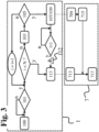
- picture 3 is a diagram of two complementary processes.
- figure 4 is a diagram of data exchange between different devices. Reference is now made to figure 2 , 3 And 4 in parallel.
- a first communication terminal 3 is in the possession of a first user 30.
- a second communication terminal 5 is in the possession of a second user 50.
- the identification device 1 is placed in a vehicle.
- the vehicle is parked and unoccupied.
- the identification device 1 is, for example, in a standby mode so that its energy consumption is limited.
- the terminals 3, 5 are located at a distance from the vehicle.
- the identification device 1 monitors 101 if a trigger event occurs. Upon detection of the triggering event, the identification device 1 exits standby mode.
- the identification device 1 emits 103 a signal pairing.
- the pairing signal takes for example the form of a BLE signal (for “Bluetooth Low Energy”). At least one of the mobile terminals 3, 5 then associates with the identification device 1.
- the triggering event comprises for example the detection of the presence of a user and/or the starting of the vehicle.
- the triggering event designates an event making it possible to anticipate an imminent use of the vehicle.
- Such an event can, for example, be detected via the accelerometer 17 described above and/or other sensors.
- the processor 11 can detect and recognize a variety of trigger events.
- the triggering event can also include an interaction of a user with the identification device 1, for example via the user interface 25.
- each of the terminals 3, 5 is able to identify itself with other compatible devices and to exchange data at short distance with other compatible devices, in particular the identification device 1.
- identification device 1 receives 105 at least one contact identifier 31, 51 from at least mobile terminal 3, 5.
- each of the terminals 3, 5 transmits to the identification device 1 a contact identifier 31, respectively 51.
- the contact identifier comprises, for example, a number of the MSISDN type for " Mobile Station Integrated Services Digital Network Number”, or more commonly “telephone number”.
- the contact identifier is of another predefined type.
- the contact ID may include a user ID that has been defined for the service.
- the contact identifiers 31, 51 Upon receipt 105 of the contact identifiers 31, 51 by the identification device 1, the contact identifiers 31, 51 are, for example, associated with an identifier 10 of the identification device 1, for example an IMSI number specific to the device identification 1.
- the method can comprise a storage 107 of the identifiers 10, 31, 51, a transmission 109 of the identifiers 10, 31, 51, or both.
- the storage operation 107 comprises the storage of the contact identifiers 31, 51 received in a memory 13 of the identification device 1, in other words a local storage.
- the transmission operation 109 comprises the prior association of the contact identifiers 31, 51 received with the identifier 10 of the identification device 1. Then, the transmission operation 109 comprises the transmission of the contact identifiers 31, 51 and of the identifier 10 of the identification device 1 associated from the identification device 1 to a remote server 7 via a mobile communication network, for example in a notification signal 40.
- the transmission of the contact identifiers 31, 51 and of the identifier 10 of the identification device 1 associated from the identification device 1 intended for a remote server 7 via a mobile communication network is implemented by calling up the memory in which the information has been stored (operation 107) only after detection of an event 60 as described below.
- the transmission of the associated identifiers 10, 31, 51 can be carried out before the detection of an event 60, for example as soon as the identifiers 31, 51 are obtained by the identification device 1 (operation 109), or else the association of identifiers 10, 31, 51 can be stored (operation 107) then transmitted (operation 113) only when an event 60 occurs.
- the two operations can also be combined.
- identification device 1 After operations 107 and/or 109, identification device 1 performs monitoring 111 (monitoring mode). The identification device 1 monitors 111 if an event 60 occurs among several predefined events. Upon detection of an event 60, the identification device 1 switches to notification mode. A notification signal 40 is transmitted 113 by the identification device 1. The notification signal 40 is transmitted to the remote server 7 via a mobile communication network.
- the contact identifiers 31, 51 stored 107 are transmitted in association with the identifier 10 of the identification device 1 from the identification device 1 to the remote server 7 via a mobile communication network with detection of the event 60.
- the transmission of the association of the identifiers of identification 10 and contact 31, 51 and the transmission of the notification signal 40 can, for example, be concomitant.
- the notification signal 40 can include the association of the identifiers of identification 10 and contact 31, 51.
- the event 60 corresponds for example to an event considered as requiring the assistance of an external operator, for example the triggering of an intervention team.
- the method implemented by the identification device 1 can be considered finished. Depending on the situation, the identification device 1 can return to the initial situation 100 or to the monitoring situation 111, automatically or in response to an interaction by a user via the interface. user 25.
- a confirmation signal specific to each of the aforementioned situations can be provided.
- the “success” signals can be at least partly common (for example the emission of a green color).
- the “failure” signals can be at least partly common (for example the emission of a red color).
- a positive confirmation signal for example the emission of a green color
- a negative confirmation signal for example the emission of a red color
- the confirmation signals can take other forms as explained above (sequences of flashes, sound, etc.).
- the reiteration loop can be infinite: the identification device 1 waits indefinitely to obtain contact identifiers 31, 51.
- the maximum number N of iterations is predefined.
- the identification device 1 implements the operation 113 of transmitting a notification signal 40.
- the contact identifiers are unavailable.
- the notification signal includes the identifier 10 of the identification device 1.
- the notification signal 40 can then include information indicating that a triggering event has been detected but that no occupant could be identified. Such a notification signal 40 can thus be interpreted as an unexpected or unauthorized use of the vehicle, for example an attempted break-in or theft.
- the detection of the start of the vehicle in the absence of a reception 105 of a contact identifier 31, 51 generates the transmission 113 of the notification signal 40 without reiteration of the operations 103 and 105 or after a number Limited number of chess.
- the emission of such a notification signal 40 indicating the absence of received contact identifier can also be combined with the implementation of a “negative” confirmation signal.
- the emission of such a notification signal 40 can be concomitant with a flashing in red and/or an audible signal from the control unit 15 of the identification device 1.
- the method is again implemented following a trigger by a user, for example by an action on the user interface 25.
- a user can activate the means of communication at a short distance from his terminal. , then cause operations 103 and 105 to be repeated.
- the limit in number N of iterations can also be replaced by, or combined with, a maximum time limit.
- the identification device 1 then comprises a clock.
- the server 7 also receives data making it possible to locate the vehicle on start-up, respectively data making it possible to locate the vehicle when the event 60 occurs.
- Server 7 includes a processor. As a variant, several processors can cooperate to implement the method described below.
- the processor, or data processing unit (CPU) is associated with a memory 73.
- the memory 73 comprises for example a random access memory (RAM), read only memory (ROM), cache memory and/or flash memory, or any other storage medium suitable for storing software code in the form of instructions executable by a processor or data structures accessible by a processor.
- the server 7 is connected to a mobile communication network so that it is capable of exchanging data, in particular with the identification device 1 as described above.
- the server 7 comprises fixed and remote equipment from the identification device 1.
- remote we mean that short-distance data exchange means cannot suffice to put the device into communication. identification 1 and server 7 with each other.
- the communication method implemented by the server 7 comprises the reception 713 of the association of the identifier 10 of the identification device 1 and at least one contact identifier 31, 51 from the remote identification device 1 via a mobile communication network.
- the server 7 Upon receipt 713 of the identifier of the identification device 1 and of at least one contact identifier 31, 51, the server 7 stores the contact identifier 31, 51 received in association with the identifier 10 of the identification 1 and deduces 717 as a function of the identifier 31, 51 of contact received a user identifier, or here a telephone identifier, for example of the MSISDN type, or more commonly a telephone number, to implement a service in function of the identifier of the identification device. It is recalled here that the device and contact identifiers can be received in a notification signal 40.
- the deduction 717 can be implemented in several ways, for example depending on the identifiers included in the notification signal 40 (or transmitted concomitantly).
- the deduction 717 of the at least one telephone identifier includes a comparison between the at least one identifier included in the notification signal 40 with data stored in a database, for example stored in the memory 73.
- the server 7 can, for example, compare the identifier 10 of the identification device 1 with the content of the database. In other words, the server 7 interrogates a database with the identifier 10 of the identification device 1.
- the database comprises for example a list of correspondence between identifiers 10 of identification devices 1 and contact IDs.
- the server 7 receives, in response, at least one corresponding contact identifier.
- the database contact IDs are default contact IDs.
- contact identifiers were provided when subscribing to the service by a user who had acquired the identification device 1. This may correspond, for example, to the situation described above for which the identification device 1 did not receive a contact identifier 31, 51 during an activation session of the identification device 1 (for example a break-in or theft attempt).
- the server 7 prior to the reception 713 of the notification signal 40, receives 709 from the remote identification device 1 via a mobile communication network, an association of at least one contact identifier 31, 51 and an identifier 10 of the identification device 1.
- This situation corresponds, for example, to that described above for which the identification device 1 implements the transmission 109 of the contact identifiers 31, 51 upon receipt from the corresponding terminals 3, 5.
- the server 7 Upon receipt 713 by the server 7, the server 7 stores 715 the association of the identifiers 10, 31, 51 in the memory 73. For example, the correspondence list mentioned above is updated.
- the update may comprise the replacement of the previous contact identifiers (for example those by default) by the current contact identifiers 31, 51 and corresponding to the terminals 3, 5 detected in the vehicle.
- the replacement may be permanent or limited to the duration of the session. When the replacement is limited to the duration of the session, default contact identifiers are for example restored when the identification device 1 is reset, for example at the end of a journey with the vehicle.
- the update may also include the addition of contact identifiers 31, 51 to those already present.
- the list can also include priority rules so that the contact identifiers are prioritized relative to each other. For example, the order in which contact identifiers should be used by an operator is predetermined.
- the deduction of at least one telephone identifier allows an operator, to whom the telephone identifier is provided, to establish communication with a telephone terminal corresponding to the deduced telephone identifier. It is emphasized here that this telephone terminal is distinct from the identification device 1.
- the telephone terminal can be one of the terminals 3, 5 identified during the session.
- the server 7 can transmit reception confirmation signals 70 to the identification device 1. Such signals can be interpreted by the identification device 1 to adapt the confirmation signals intended for the occupants of the vehicle .
- the identification device 1 can be understood as a transmitter transmitting data to the server, while the server can be seen as a receiver of said data and able to process them to identify a user present in the vehicle.
- the server can be seen as a receiver of said data and able to process them to identify a user present in the vehicle.
- this allows the server in particular to deduce a telephone identifier, to contact a user via a terminal separate from the identification device 1.
- one of the intended applications is the call of the presumed occupants of the vehicle when an event such as an accident is detected.
- the telephone identifiers make it possible, in addition, to contact other users such as a reference person.
- a reference person can include the owner of the vehicle, a manager in the case of a company vehicle, an automotive professional to facilitate the payment of mechanical repairs or even an insurance company to speed up the administrative operations resulting from a possible accident.
- the proposed methods are described in different embodiments as implemented respectively by an identification device 1 as illustrated in the figure 1 and by a server 7 as shown in picture 2 , different embodiments of the proposed methods can be implemented using different types of devices such as computers, tablets or computer resources remote from each other.
- the first method is implemented by computer means placed in a vehicle and configured to process data from terminals 3, 5.
- the second method is implemented by computer means remote from the vehicle and configured to process data from the first computer means.
- the identification device 1 can be supplied with a processing device including an operating system and programs, components, modules and/or applications in the form of software executed by the processor(s) 11, which can be stored in non-volatile memory.
- a processing device including an operating system and programs, components, modules and/or applications in the form of software executed by the processor(s) 11, which can be stored in non-volatile memory.
- the invention is not limited to the examples of systems, methods, identification devices, data processing units, recording media and programs described above, solely by way of example, but it encompasses all the variants that will be able to consider the person skilled in the art within the framework of the protection sought.
Landscapes
- Physics & Mathematics (AREA)
- General Physics & Mathematics (AREA)
- Engineering & Computer Science (AREA)
- Computer Security & Cryptography (AREA)
- Business, Economics & Management (AREA)
- Emergency Management (AREA)
- Telephonic Communication Services (AREA)
- Mobile Radio Communication Systems (AREA)
Claims (13)
- Kommunikationsverfahren, das von einer Identifizierungsvorrichtung (1) durchgeführt wird, die dazu geeignet ist, in einem Fahrzeug angeordnet zu werden, wobei das Verfahren umfasst:- Empfangen (105) einer Kontaktkennung (31, 51) von mindestens einem mobilen Endgerät (3, 5) eines im Fahrzeug sitzenden Benutzers, das dazu fähig ist, Daten über eine kurze Strecke auszutauschen, um sich mit der Identifizierungsvorrichtung (1) zu paaren,- Übertragen (109, 113) der empfangenen Kontaktkennung (31, 51), die einer Kennung (10) der Identifizierungsvorrichtung (1) zugeordnet ist, von der Identifizierungsvorrichtung (1) zu einem entfernten Server (7) über ein Mobilkommunikationsnetz, wobei die mindestens eine übertragene Kontaktkennung (10, 31, 51), dem Server ermöglicht, eine Benutzerkennung abzuleiten, um abhängig von der Kennung (10) der Identifizierungsvorrichtung (1) einen Dienst auszuführen,wobei die Identifizierungsvorrichtung (1) mindestens ein Bestätigungssignal erzeugt, das durch einen Fahrzeuginsassen wahrnehmbar ist, wobei das Bestätigungssignal so ausgewählt wird, dass es unterscheidet:- zwischen Erfolg und Scheitern des Empfangs einer Kontaktkennung (31, 51) eines mobilen Endgeräts (3, 5) das dazu fähig ist, über eine kurze Strecke mit der Identifizierungsvorrichtung (1) Daten auszutauschen,- zwischen Erfolg und Scheitern der Übertragung (109, 113) der Kontaktkennung (31, 51), die der Kennung (10) der Identifizierungsvorrichtung (1) zugeordnet ist, und- zwischen Erfolg und Scheitern der Übertragung (113) des Meldesignals (40).
- Verfahren nach Anspruch 1, wobei die Übertragung (109) der Kontaktkennung (31, 51), die einer Kennung (10) der Identifizierungsvorrichtung (1) zugeordnet ist, ab Empfang der Kontaktkennung (31, 51) durchgeführt wird.
- Verfahren nach einem der vorhergehenden Ansprüche, das außerdem umfasst:- Erkennen eines Ereignisses (60),- wobei die Erkennung die Übertragung der Kontaktkennung (31, 51) auslöst, die der Kennung (10) der Identifizierungsvorrichtung (1) zugeordnet ist.
- Verfahren nach Anspruch 3, wobei das Ereignis (60) in einer freiwilligen Interaktion eines Fahrzeuginsassen mit der Identifizierungsvorrichtung (1) besteht.
- Verfahren nach Anspruch 3, wobei das Ereignis (60) in einer Überschreitung eines Beschleunigungsschwellenwertes besteht, die durch einen Beschleunigungsmesser (17) der Identifizierungsvorrichtung (1) erkannt wird.
- Verfahren nach einem der vorhergehenden Ansprüche, das außerdem umfasst:- Überwachen (101) des Empfangs einer Kontaktkennung (31, 51) und/oder des Startens des Fahrzeugs durch die Identifizierungsvorrichtung (1),- bei Erkennen des Startens des Fahrzeugs ohne Empfang einer Kontaktkennung (31, 51) Übertragen eines Meldesignals (40) an den Server (7).
- Verfahren nach einem der vorhergehenden Ansprüche, wobei Geopositionsdaten (49) bei Empfang der Kontaktkennung (31, 51) und/oder Erkennung eines Ereignisses (60) übertragen werden (109, 113).
- Kommunikationsverfahren nach Anspruch 1, wobei das Verfahren die durch einen Server (7) durchgeführten folgenden Schritte umfasst:- Empfangen (713) der mindestens einen Kontaktkennung (31, 51), die einer Kennung (10) der Identifizierungsvorrichtung (1) zugeordnet ist, von einer entfernten Identifizierungsvorrichtung (1),- Ableiten (717) einer Benutzerkennung abhängig von mindestens einer empfangenen Kontaktkennung (10, 31, 51), um einen Dienst abhängig von der Kennung (10) der Identifizierungsvorrichtung (1) auszuführen.
- Verfahren nach Anspruch 8, das außerdem umfasst:- Empfangen (713) eines Meldesignals (40) durch den Server,- Aufrufen der Zuordnung (10, 31, 51), die in einer Datenbank (73) gespeichert ist, um die Benutzerkennung abzuleiten (717) und den Dienst auszuführen.
- Verfahren nach einem der Ansprüche 8 und 9, wobei die Ableitung (717) der Benutzerkennung einen Vergleich der mindestens einen Kennung (10, 31, 51) der empfangenen Zuordnung mit den in einer Datenbank (73) gespeicherten Daten beinhaltet.
- Nichttransitorisches, computerlesbares Speichermedium, auf dem ein Programm gespeichert ist, das Anweisungen zur Durchführung des Verfahrens nach einem der Ansprüche 1 bis 10 umfasst.
- Computerprogramm, das Anweisungen zur Durchführung des Verfahrens nach einem der Ansprüche 1 bis 10 umfasst, wenn das Programm durch einen Prozessor (11) ausgeführt wird.
- Identifizierungsvorrichtung (1), die dazu geeignet ist, in einem Fahrzeug angeordnet zu werden und einen Prozessor (11) umfasst, der funktionsfähig mit einem Speicher (13) verbunden ist, wobei die Vorrichtung außerdem umfasst:- ein Kurzstrecken-Kommunikationsmodul (21), das dazu eingerichtet ist, eine Kontaktkennung (31, 51) von mindestens einem mobilen Endgerät (3, 5) eines Fahrzeuginsassen zu empfangen, das dazu fähig ist, Daten über eine kurze Strecke auszutauschen, um sich mit der Identifizierungsvorrichtung (1) zu paaren,- ein mobiles Kommunikationsmodul (23), das dazu eingerichtet ist, die empfangene Kontaktkennung (31, 51), die einer Kennung (10) der Identifizierungsvorrichtung (1) zugeordnet ist, von der Identifizierungsvorrichtung (1) über ein Mobilkommunikationsnetz zu einem entfernten Server (7) zu übertragen, wobei die mindestens eine übertragene Kontaktkennung (10, 31, 51) dem Server ermöglicht, eine Benutzerkennung abzuleiten, um abhängig von der Kennung (10) der Identifizierungsvorrichtung (1) einen Dienst auszuführen,wobei die Identifizierungsvorrichtung (1) außerdem dazu eingerichtet ist, mindestens ein Bestätigungssignal zu erzeugen, das durch einen Fahrzeuginsassen wahrnehmbar ist, wobei das Bestätigungssignal so ausgewählt wird, dass es unterscheidet:- zwischen Erfolg und Scheitern des Empfangs einer Kontaktkennung (31, 51) eines mobilen Endgeräts (3, 5) das dazu fähig ist, über eine kurze Strecke mit der Identifizierungsvorrichtung (1) Daten auszutauschen,- zwischen Erfolg und Scheitern der Übertragung (109, 113) der Kontaktkennung (31, 51), die der Kennung (10) der Identifizierungsvorrichtung (1) zugeordnet ist, und- zwischen Erfolg und Scheitern der Übertragung (113) des Meldesignals (40).
Applications Claiming Priority (2)
| Application Number | Priority Date | Filing Date | Title |
|---|---|---|---|
| FR1753419A FR3065564A1 (fr) | 2017-04-20 | 2017-04-20 | Identification a bord d'un vehicule |
| PCT/FR2018/050959 WO2018193202A1 (fr) | 2017-04-20 | 2018-04-17 | Identification à bord d'un véhicule |
Publications (2)
| Publication Number | Publication Date |
|---|---|
| EP3613029A1 EP3613029A1 (de) | 2020-02-26 |
| EP3613029B1 true EP3613029B1 (de) | 2023-06-28 |
Family
ID=59325444
Family Applications (1)
| Application Number | Title | Priority Date | Filing Date |
|---|---|---|---|
| EP18720339.3A Active EP3613029B1 (de) | 2017-04-20 | 2018-04-17 | Identifizierung an bord eines fahrzeugs |
Country Status (3)
| Country | Link |
|---|---|
| EP (1) | EP3613029B1 (de) |
| FR (1) | FR3065564A1 (de) |
| WO (1) | WO2018193202A1 (de) |
Families Citing this family (2)
| Publication number | Priority date | Publication date | Assignee | Title |
|---|---|---|---|---|
| FR3093853B1 (fr) * | 2019-03-15 | 2022-07-29 | Continental Automotive Gmbh | Procédé d’émission de demandes de secours pour vehicule |
| FR3136622B1 (fr) * | 2022-06-14 | 2024-06-21 | Orange | Procédé d’identification d’un équipement ayant associé un identifiant réseau, et procédé de fourniture de l’identité d’un équipement dans un réseau de communication. |
Citations (2)
| Publication number | Priority date | Publication date | Assignee | Title |
|---|---|---|---|---|
| EP1422676A1 (de) * | 2001-08-10 | 2004-05-26 | Omron Corporation | Mobilkommunikationsvorrichtung, überwachungsvorrichtung, überwachungssystem, überwachungsverfahren, überwachungsprogramm und computerlesbares aufzeichnungsmedium, das das überwachungsprogramm enthält |
| US20150061851A1 (en) * | 2013-08-28 | 2015-03-05 | Omron Automotive Electronics Co., Ltd. | Onboard apparatus and report control method |
Family Cites Families (3)
| Publication number | Priority date | Publication date | Assignee | Title |
|---|---|---|---|---|
| SE9904865D0 (sv) * | 1999-12-30 | 1999-12-30 | Satsafe Mls Ab | Kommunikationsoberoende ID-enhet |
| US20110260859A1 (en) * | 2010-04-27 | 2011-10-27 | Mgm Computer Systems, Inc. | Indoor and outdoor security system and method of use |
| US20170015263A1 (en) * | 2015-07-14 | 2017-01-19 | Ford Global Technologies, Llc | Vehicle Emergency Broadcast |
-
2017
- 2017-04-20 FR FR1753419A patent/FR3065564A1/fr active Pending
-
2018
- 2018-04-17 WO PCT/FR2018/050959 patent/WO2018193202A1/fr unknown
- 2018-04-17 EP EP18720339.3A patent/EP3613029B1/de active Active
Patent Citations (2)
| Publication number | Priority date | Publication date | Assignee | Title |
|---|---|---|---|---|
| EP1422676A1 (de) * | 2001-08-10 | 2004-05-26 | Omron Corporation | Mobilkommunikationsvorrichtung, überwachungsvorrichtung, überwachungssystem, überwachungsverfahren, überwachungsprogramm und computerlesbares aufzeichnungsmedium, das das überwachungsprogramm enthält |
| US20150061851A1 (en) * | 2013-08-28 | 2015-03-05 | Omron Automotive Electronics Co., Ltd. | Onboard apparatus and report control method |
Also Published As
| Publication number | Publication date |
|---|---|
| WO2018193202A1 (fr) | 2018-10-25 |
| EP3613029A1 (de) | 2020-02-26 |
| FR3065564A1 (fr) | 2018-10-26 |
Similar Documents
| Publication | Publication Date | Title |
|---|---|---|
| EP3083343B1 (de) | Verfahren zum ausführen eines befehls für ein kraftfahrzeug durch datenaustausch zwischen einer steuereinheit und einem identifikationsgeber | |
| US20130226369A1 (en) | Portable vehicle telematics systems and methods | |
| US20150099500A1 (en) | Vehicle operator/driver and wireless device synchronization and uses thereof | |
| US20140066000A1 (en) | Mobile Emergency Attack and Failsafe Detection | |
| EP3227155B1 (de) | Verfahren zur unterstützung von mindestens einem insassen eines von einem unfall betroffenen fahrzeugs und dediziertes hilfssystem | |
| CN104735615A (zh) | 移动终端定位方法、信息发送方法、装置、终端及设备 | |
| EP2727096A1 (de) | Verfahren und system zur überwachung eines leihwagens | |
| EP3613029B1 (de) | Identifizierung an bord eines fahrzeugs | |
| EP2168283A1 (de) | Verfahren zur detektion der verschlüsselung eines funkkommunikationsnetzwerkes sowie entsprechendes computerprogrammprodukt, speichermittel und schaltung | |
| EP1074441A1 (de) | Prozessfernsteuerungsverfahren | |
| EP1488395B1 (de) | Mobilfunkkommunikationvorrichtung für kurze distanzen und zugehöriges sende-empfangs-modul und diebstahlschutz hierzu | |
| CN105045380A (zh) | 智能手机及基于车辆运动状态的智能电话提醒讯息的反馈方法 | |
| EP3143601A1 (de) | Vorrichtung zur steuerung der von einem artikel einer bordseitigen ausrüstung getragenen daten | |
| FR3097674A1 (fr) | Véhicule équipé d’un système de détection de véhicule d’urgence. | |
| EP4029318B1 (de) | Kommunikationsverfahren zwischen einem fahrzeugsteuerungssystem und einer vielzahl von mobilen kommunikationsvorrichtungen | |
| WO2017198926A1 (fr) | Procédé et système de transmission d'une alerte géolocalisée a un utilisateur muni d'un terminal mobile de communication | |
| WO2013186331A1 (fr) | Dispositif de communication. | |
| WO2009039901A1 (fr) | Système de transmission d'énergie comprenant une clé électronique d'un véhicule, clé électronique d'un véhicule, système de communication comprenant une clé électronique d'un véhicule et procédé de communication d'une information de position | |
| FR2896934A1 (fr) | Composant integre comprenant des circuits de gestion de l'alimentation et de gestion des etats d'urgence | |
| FR3099108A1 (fr) | Dispositif de centralisation d'accessoires | |
| FR2977216A1 (fr) | Procede, systeme et installation de detection d'une utilisation frauduleuse d'un vehicule | |
| WO2004111970A2 (fr) | Procede et dispositif de lutte contre le vol d’un appareil de radiocommunication | |
| FR2926385A1 (fr) | Cle electronique d'un vehicule, systeme de communication comprenant une cle electronique d'un vehicule et procede de communication | |
| EP2642460A1 (de) | Alarmverfahren über ein mobiles Endgerät | |
| EP3436332A1 (de) | Autonome vorrichtung zur warnung im fall einer fahrzeugbewegung |
Legal Events
| Date | Code | Title | Description |
|---|---|---|---|
| STAA | Information on the status of an ep patent application or granted ep patent |
Free format text: STATUS: UNKNOWN |
|
| STAA | Information on the status of an ep patent application or granted ep patent |
Free format text: STATUS: THE INTERNATIONAL PUBLICATION HAS BEEN MADE |
|
| PUAI | Public reference made under article 153(3) epc to a published international application that has entered the european phase |
Free format text: ORIGINAL CODE: 0009012 |
|
| STAA | Information on the status of an ep patent application or granted ep patent |
Free format text: STATUS: REQUEST FOR EXAMINATION WAS MADE |
|
| 17P | Request for examination filed |
Effective date: 20190823 |
|
| AK | Designated contracting states |
Kind code of ref document: A1 Designated state(s): AL AT BE BG CH CY CZ DE DK EE ES FI FR GB GR HR HU IE IS IT LI LT LU LV MC MK MT NL NO PL PT RO RS SE SI SK SM TR |
|
| AX | Request for extension of the european patent |
Extension state: BA ME |
|
| RAP1 | Party data changed (applicant data changed or rights of an application transferred) |
Owner name: ORANGE |
|
| DAV | Request for validation of the european patent (deleted) | ||
| DAX | Request for extension of the european patent (deleted) | ||
| RAP3 | Party data changed (applicant data changed or rights of an application transferred) |
Owner name: ORANGE |
|
| STAA | Information on the status of an ep patent application or granted ep patent |
Free format text: STATUS: EXAMINATION IS IN PROGRESS |
|
| 17Q | First examination report despatched |
Effective date: 20211027 |
|
| GRAP | Despatch of communication of intention to grant a patent |
Free format text: ORIGINAL CODE: EPIDOSNIGR1 |
|
| STAA | Information on the status of an ep patent application or granted ep patent |
Free format text: STATUS: GRANT OF PATENT IS INTENDED |
|
| RIC1 | Information provided on ipc code assigned before grant |
Ipc: G08G 1/017 19900101ALI20230112BHEP Ipc: G08G 1/00 19680901ALI20230112BHEP Ipc: G08B 25/01 19900101AFI20230112BHEP |
|
| INTG | Intention to grant announced |
Effective date: 20230206 |
|
| GRAS | Grant fee paid |
Free format text: ORIGINAL CODE: EPIDOSNIGR3 |
|
| GRAA | (expected) grant |
Free format text: ORIGINAL CODE: 0009210 |
|
| STAA | Information on the status of an ep patent application or granted ep patent |
Free format text: STATUS: THE PATENT HAS BEEN GRANTED |
|
| AK | Designated contracting states |
Kind code of ref document: B1 Designated state(s): AL AT BE BG CH CY CZ DE DK EE ES FI FR GB GR HR HU IE IS IT LI LT LU LV MC MK MT NL NO PL PT RO RS SE SI SK SM TR |
|
| REG | Reference to a national code |
Ref country code: CH Ref legal event code: EP |
|
| REG | Reference to a national code |
Ref country code: AT Ref legal event code: REF Ref document number: 1583429 Country of ref document: AT Kind code of ref document: T Effective date: 20230715 |
|
| REG | Reference to a national code |
Ref country code: IE Ref legal event code: FG4D Free format text: LANGUAGE OF EP DOCUMENT: FRENCH |
|
| REG | Reference to a national code |
Ref country code: DE Ref legal event code: R096 Ref document number: 602018052402 Country of ref document: DE |
|
| REG | Reference to a national code |
Ref country code: LT Ref legal event code: MG9D |
|
| PG25 | Lapsed in a contracting state [announced via postgrant information from national office to epo] |
Ref country code: SE Free format text: LAPSE BECAUSE OF FAILURE TO SUBMIT A TRANSLATION OF THE DESCRIPTION OR TO PAY THE FEE WITHIN THE PRESCRIBED TIME-LIMIT Effective date: 20230628 Ref country code: NO Free format text: LAPSE BECAUSE OF FAILURE TO SUBMIT A TRANSLATION OF THE DESCRIPTION OR TO PAY THE FEE WITHIN THE PRESCRIBED TIME-LIMIT Effective date: 20230928 |
|
| REG | Reference to a national code |
Ref country code: NL Ref legal event code: MP Effective date: 20230628 |
|
| REG | Reference to a national code |
Ref country code: AT Ref legal event code: MK05 Ref document number: 1583429 Country of ref document: AT Kind code of ref document: T Effective date: 20230628 |
|
| PG25 | Lapsed in a contracting state [announced via postgrant information from national office to epo] |
Ref country code: RS Free format text: LAPSE BECAUSE OF FAILURE TO SUBMIT A TRANSLATION OF THE DESCRIPTION OR TO PAY THE FEE WITHIN THE PRESCRIBED TIME-LIMIT Effective date: 20230628 Ref country code: NL Free format text: LAPSE BECAUSE OF FAILURE TO SUBMIT A TRANSLATION OF THE DESCRIPTION OR TO PAY THE FEE WITHIN THE PRESCRIBED TIME-LIMIT Effective date: 20230628 Ref country code: LV Free format text: LAPSE BECAUSE OF FAILURE TO SUBMIT A TRANSLATION OF THE DESCRIPTION OR TO PAY THE FEE WITHIN THE PRESCRIBED TIME-LIMIT Effective date: 20230628 Ref country code: LT Free format text: LAPSE BECAUSE OF FAILURE TO SUBMIT A TRANSLATION OF THE DESCRIPTION OR TO PAY THE FEE WITHIN THE PRESCRIBED TIME-LIMIT Effective date: 20230628 Ref country code: HR Free format text: LAPSE BECAUSE OF FAILURE TO SUBMIT A TRANSLATION OF THE DESCRIPTION OR TO PAY THE FEE WITHIN THE PRESCRIBED TIME-LIMIT Effective date: 20230628 Ref country code: GR Free format text: LAPSE BECAUSE OF FAILURE TO SUBMIT A TRANSLATION OF THE DESCRIPTION OR TO PAY THE FEE WITHIN THE PRESCRIBED TIME-LIMIT Effective date: 20230929 |
|
| PG25 | Lapsed in a contracting state [announced via postgrant information from national office to epo] |
Ref country code: FI Free format text: LAPSE BECAUSE OF FAILURE TO SUBMIT A TRANSLATION OF THE DESCRIPTION OR TO PAY THE FEE WITHIN THE PRESCRIBED TIME-LIMIT Effective date: 20230628 |
|
| PG25 | Lapsed in a contracting state [announced via postgrant information from national office to epo] |
Ref country code: SK Free format text: LAPSE BECAUSE OF FAILURE TO SUBMIT A TRANSLATION OF THE DESCRIPTION OR TO PAY THE FEE WITHIN THE PRESCRIBED TIME-LIMIT Effective date: 20230628 |
|
| PG25 | Lapsed in a contracting state [announced via postgrant information from national office to epo] |
Ref country code: ES Free format text: LAPSE BECAUSE OF FAILURE TO SUBMIT A TRANSLATION OF THE DESCRIPTION OR TO PAY THE FEE WITHIN THE PRESCRIBED TIME-LIMIT Effective date: 20230628 |
|
| PG25 | Lapsed in a contracting state [announced via postgrant information from national office to epo] |
Ref country code: IS Free format text: LAPSE BECAUSE OF FAILURE TO SUBMIT A TRANSLATION OF THE DESCRIPTION OR TO PAY THE FEE WITHIN THE PRESCRIBED TIME-LIMIT Effective date: 20231028 |
|
| PG25 | Lapsed in a contracting state [announced via postgrant information from national office to epo] |
Ref country code: SM Free format text: LAPSE BECAUSE OF FAILURE TO SUBMIT A TRANSLATION OF THE DESCRIPTION OR TO PAY THE FEE WITHIN THE PRESCRIBED TIME-LIMIT Effective date: 20230628 Ref country code: SK Free format text: LAPSE BECAUSE OF FAILURE TO SUBMIT A TRANSLATION OF THE DESCRIPTION OR TO PAY THE FEE WITHIN THE PRESCRIBED TIME-LIMIT Effective date: 20230628 Ref country code: RO Free format text: LAPSE BECAUSE OF FAILURE TO SUBMIT A TRANSLATION OF THE DESCRIPTION OR TO PAY THE FEE WITHIN THE PRESCRIBED TIME-LIMIT Effective date: 20230628 Ref country code: PT Free format text: LAPSE BECAUSE OF FAILURE TO SUBMIT A TRANSLATION OF THE DESCRIPTION OR TO PAY THE FEE WITHIN THE PRESCRIBED TIME-LIMIT Effective date: 20231030 Ref country code: IS Free format text: LAPSE BECAUSE OF FAILURE TO SUBMIT A TRANSLATION OF THE DESCRIPTION OR TO PAY THE FEE WITHIN THE PRESCRIBED TIME-LIMIT Effective date: 20231028 Ref country code: ES Free format text: LAPSE BECAUSE OF FAILURE TO SUBMIT A TRANSLATION OF THE DESCRIPTION OR TO PAY THE FEE WITHIN THE PRESCRIBED TIME-LIMIT Effective date: 20230628 Ref country code: EE Free format text: LAPSE BECAUSE OF FAILURE TO SUBMIT A TRANSLATION OF THE DESCRIPTION OR TO PAY THE FEE WITHIN THE PRESCRIBED TIME-LIMIT Effective date: 20230628 Ref country code: CZ Free format text: LAPSE BECAUSE OF FAILURE TO SUBMIT A TRANSLATION OF THE DESCRIPTION OR TO PAY THE FEE WITHIN THE PRESCRIBED TIME-LIMIT Effective date: 20230628 Ref country code: AT Free format text: LAPSE BECAUSE OF FAILURE TO SUBMIT A TRANSLATION OF THE DESCRIPTION OR TO PAY THE FEE WITHIN THE PRESCRIBED TIME-LIMIT Effective date: 20230628 |
|
| PG25 | Lapsed in a contracting state [announced via postgrant information from national office to epo] |
Ref country code: PL Free format text: LAPSE BECAUSE OF FAILURE TO SUBMIT A TRANSLATION OF THE DESCRIPTION OR TO PAY THE FEE WITHIN THE PRESCRIBED TIME-LIMIT Effective date: 20230628 |
|
| REG | Reference to a national code |
Ref country code: DE Ref legal event code: R097 Ref document number: 602018052402 Country of ref document: DE |
|
| PG25 | Lapsed in a contracting state [announced via postgrant information from national office to epo] |
Ref country code: DK Free format text: LAPSE BECAUSE OF FAILURE TO SUBMIT A TRANSLATION OF THE DESCRIPTION OR TO PAY THE FEE WITHIN THE PRESCRIBED TIME-LIMIT Effective date: 20230628 |
|
| PGFP | Annual fee paid to national office [announced via postgrant information from national office to epo] |
Ref country code: GB Payment date: 20240320 Year of fee payment: 7 |
|
| PLBE | No opposition filed within time limit |
Free format text: ORIGINAL CODE: 0009261 |
|
| STAA | Information on the status of an ep patent application or granted ep patent |
Free format text: STATUS: NO OPPOSITION FILED WITHIN TIME LIMIT |
|
| PG25 | Lapsed in a contracting state [announced via postgrant information from national office to epo] |
Ref country code: IT Free format text: LAPSE BECAUSE OF FAILURE TO SUBMIT A TRANSLATION OF THE DESCRIPTION OR TO PAY THE FEE WITHIN THE PRESCRIBED TIME-LIMIT Effective date: 20230628 |
|
| PGFP | Annual fee paid to national office [announced via postgrant information from national office to epo] |
Ref country code: FR Payment date: 20240320 Year of fee payment: 7 |
|
| 26N | No opposition filed |
Effective date: 20240402 |
|
| PGFP | Annual fee paid to national office [announced via postgrant information from national office to epo] |
Ref country code: DE Payment date: 20240320 Year of fee payment: 7 |
|
| PG25 | Lapsed in a contracting state [announced via postgrant information from national office to epo] |
Ref country code: SI Free format text: LAPSE BECAUSE OF FAILURE TO SUBMIT A TRANSLATION OF THE DESCRIPTION OR TO PAY THE FEE WITHIN THE PRESCRIBED TIME-LIMIT Effective date: 20230628 |