EP3612929B1 - Rules based user interface generation - Google Patents
Rules based user interface generation Download PDFInfo
- Publication number
- EP3612929B1 EP3612929B1 EP17734911.5A EP17734911A EP3612929B1 EP 3612929 B1 EP3612929 B1 EP 3612929B1 EP 17734911 A EP17734911 A EP 17734911A EP 3612929 B1 EP3612929 B1 EP 3612929B1
- Authority
- EP
- European Patent Office
- Prior art keywords
- user interface
- interface manager
- manager
- rules
- application
- Prior art date
- Legal status (The legal status is an assumption and is not a legal conclusion. Google has not performed a legal analysis and makes no representation as to the accuracy of the status listed.)
- Active
Links
- 238000000034 method Methods 0.000 claims description 46
- 230000000007 visual effect Effects 0.000 claims description 35
- 230000003190 augmentative effect Effects 0.000 claims description 8
- 230000004044 response Effects 0.000 claims description 7
- 238000010586 diagram Methods 0.000 description 13
- 230000006870 function Effects 0.000 description 13
- 230000008569 process Effects 0.000 description 9
- 238000005516 engineering process Methods 0.000 description 8
- 238000012545 processing Methods 0.000 description 7
- 238000004891 communication Methods 0.000 description 5
- 230000009471 action Effects 0.000 description 4
- 238000005192 partition Methods 0.000 description 4
- 238000007726 management method Methods 0.000 description 3
- 239000000203 mixture Substances 0.000 description 3
- 230000007704 transition Effects 0.000 description 3
- 241000699666 Mus <mouse, genus> Species 0.000 description 2
- 241000699670 Mus sp. Species 0.000 description 2
- 239000008186 active pharmaceutical agent Substances 0.000 description 2
- 230000008901 benefit Effects 0.000 description 2
- 230000001413 cellular effect Effects 0.000 description 2
- 238000013461 design Methods 0.000 description 2
- 238000001514 detection method Methods 0.000 description 2
- 230000000694 effects Effects 0.000 description 2
- 238000004519 manufacturing process Methods 0.000 description 2
- 230000003287 optical effect Effects 0.000 description 2
- 239000003973 paint Substances 0.000 description 2
- 230000002085 persistent effect Effects 0.000 description 2
- 230000003068 static effect Effects 0.000 description 2
- RYGMFSIKBFXOCR-UHFFFAOYSA-N Copper Chemical compound [Cu] RYGMFSIKBFXOCR-UHFFFAOYSA-N 0.000 description 1
- 101000857680 Xenopus laevis Runt-related transcription factor 1 Proteins 0.000 description 1
- 230000004913 activation Effects 0.000 description 1
- 238000013459 approach Methods 0.000 description 1
- 230000006399 behavior Effects 0.000 description 1
- 230000005540 biological transmission Effects 0.000 description 1
- 210000004556 brain Anatomy 0.000 description 1
- 230000007177 brain activity Effects 0.000 description 1
- 230000008859 change Effects 0.000 description 1
- 238000004590 computer program Methods 0.000 description 1
- 229910052802 copper Inorganic materials 0.000 description 1
- 239000010949 copper Substances 0.000 description 1
- 230000008878 coupling Effects 0.000 description 1
- 238000010168 coupling process Methods 0.000 description 1
- 238000005859 coupling reaction Methods 0.000 description 1
- 238000013499 data model Methods 0.000 description 1
- 230000001419 dependent effect Effects 0.000 description 1
- 230000009977 dual effect Effects 0.000 description 1
- 230000005684 electric field Effects 0.000 description 1
- 238000000537 electroencephalography Methods 0.000 description 1
- 230000001815 facial effect Effects 0.000 description 1
- 239000000835 fiber Substances 0.000 description 1
- 230000003116 impacting effect Effects 0.000 description 1
- 230000003993 interaction Effects 0.000 description 1
- 238000013507 mapping Methods 0.000 description 1
- 238000003032 molecular docking Methods 0.000 description 1
- 230000002093 peripheral effect Effects 0.000 description 1
- 238000000638 solvent extraction Methods 0.000 description 1
- 230000001360 synchronised effect Effects 0.000 description 1
- 238000012546 transfer Methods 0.000 description 1
Images


Classifications
-
- G—PHYSICS
- G06—COMPUTING; CALCULATING OR COUNTING
- G06F—ELECTRIC DIGITAL DATA PROCESSING
- G06F9/00—Arrangements for program control, e.g. control units
- G06F9/06—Arrangements for program control, e.g. control units using stored programs, i.e. using an internal store of processing equipment to receive or retain programs
- G06F9/44—Arrangements for executing specific programs
- G06F9/451—Execution arrangements for user interfaces
-
- G—PHYSICS
- G06—COMPUTING; CALCULATING OR COUNTING
- G06F—ELECTRIC DIGITAL DATA PROCESSING
- G06F3/00—Input arrangements for transferring data to be processed into a form capable of being handled by the computer; Output arrangements for transferring data from processing unit to output unit, e.g. interface arrangements
- G06F3/01—Input arrangements or combined input and output arrangements for interaction between user and computer
- G06F3/048—Interaction techniques based on graphical user interfaces [GUI]
- G06F3/0484—Interaction techniques based on graphical user interfaces [GUI] for the control of specific functions or operations, e.g. selecting or manipulating an object, an image or a displayed text element, setting a parameter value or selecting a range
Definitions
- Computer devices of any size can generate a user experience, which is typically fixed to the intended design.
- Each device can separately generate a user interface based on fixed application functions. For example, each device can separately generate a user interface by hard coding or using a fixed format for displaying applications.
- US 2013/0167111 A1 discloses systems and methods for developing multiplatform applications for computing devices which include actions of transmitting a first user interface engine to a first computing device, the first user interface engine being specific to a first operating system of the first computing device, and transmitting a second user interface engine to a second computing device, the second user interface engine being specific to a second operating system of the second computing system, the first operating system being different from the second operating system.
- US 7,907,966 B1 discloses a system and method for operation of cross-platform applications on a wireless phone, wherein the wireless phone processor can operate to determine platform parameters of the phone and then run the cross-platform application using the determined phone parameters.
- a system for generating a user interface includes a processor and a storage device to store a plurality of instructions that, in response to being executed by the processor, cause the processor to detect a type of the system based on hardware components residing within the system or coupled to the system.
- the processor also determines a user interface manager to execute based on the type of the system and executes the user interface manager to generate a user interface for the system, wherein the user interface manager comprises a plurality of rules to indicate a layout of the user interface.
- the user interface manager comprises a shared code including a plurality of rules to indicate layouts of different user interfaces corresponding to different types of systems, and the user interface manager generates the user interface for the system based on the plurality of rules, included in the shared code, corresponding to the detected type of the system.
- a method for generating a user interface includes detecting a type of a system based on hardware components residing within the system or coupled to the system. The method also includes determining a user interface manager to execute based on the type of the system and executing the user interface manager to generate a user interface for the system, wherein the user interface manager comprises a plurality of rules to indicate a layout of the user interface.
- the user interface manager comprises a shared code including a plurality of rules to indicate layouts of different user interfaces corresponding to different types of systems, and the user interface manager generates the user interface for the system based on the plurality of rules, included in the shared code, corresponding to the detected type of the system.
- User interfaces can be generated using various static, non-reusable techniques. For example, user interfaces for different devices can be generated using different sets of functions, different data paths, and different visual compositions. Accordingly, applications often include different code to generate a user interface for each type of device. These applications also have deep context about the device on which they are running and often map user interface controls directly to pixel coordinates on a display device. For example, the applications may specify pixel coordinates to display a user control element such as a text field, among others.
- the rules for generating a user interface for a desktop computing device can differ from the rules for generating a user interface for a mobile device.
- the system detects a type of the system based on hardware components residing within the system and determines a type of user interface manager to execute based on the type of the system.
- the system also executes the user interface manager to generate a user interface for the system, wherein the user interface manager comprises a plurality of rules to indicate a layout of the user interface.
- the techniques described herein enable code for generating user interfaces to be shared while creating user interfaces for any number of different devices.
- the techniques described herein can enable shared code to generate a user interface for a desktop device, a tablet device, a mobile device, a phone device, a gaming console device, and an augmented reality device, among others.
- the shared code can generate different user interfaces based on rules corresponding to each type of device. For example, code for displaying a user application with certain rules can be shared between any number of different user interface managers corresponding to different types of devices.
- FIG. 1 describe concepts in the context of one or more structural components, referred to as functionalities, modules, features, elements, etc.
- the various components shown in the figures can be implemented in any manner, for example, by software, hardware (e.g., discrete logic components, etc.), firmware, and so on, or any combination of these implementations.
- the various components may reflect the use of corresponding components in an actual implementation.
- any single component illustrated in the figures may be implemented by a number of actual components.
- the depiction of any two or more separate components in the figures may reflect different functions performed by a single actual component.
- Fig. 1 discussed below, provide details regarding different systems that may be used to implement the functions shown in the figures.
- the phrase “configured to” encompasses any way that any kind of structural component can be constructed to perform an identified operation.
- the structural component can be configured to perform an operation using software, hardware, firmware and the like, or any combinations thereof.
- the phrase “configured to” can refer to a logic circuit structure of a hardware element that is to implement the associated functionality.
- the phrase “configured to” can also refer to a logic circuit structure of a hardware element that is to implement the coding design of associated functionality of firmware or software.
- module refers to a structural element that can be implemented using any suitable hardware (e.g., a processor, among others), software (e.g., an application, among others), firmware, or any combination of hardware, software, and firmware.
- logic encompasses any functionality for performing a task. For instance, each operation illustrated in the flowcharts corresponds to logic for performing that operation. An operation can be performed using software, hardware, firmware, etc., or any combinations thereof.
- ком ⁇ онент can be a process running on a processor, an object, an executable, a program, a function, a library, a subroutine, and/or a computer or a combination of software and hardware.
- a component can be a process running on a processor, an object, an executable, a program, a function, a library, a subroutine, and/or a computer or a combination of software and hardware.
- an application running on a server and the server can be a component.
- One or more components can reside within a process and a component can be localized on one computer and/or distributed between two or more computers.
- the claimed subject matter may be implemented as a method, apparatus, or article of manufacture using standard programming and/or engineering techniques to produce software, firmware, hardware, or any combination thereof to control a computer to implement the disclosed subject matter.
- article of manufacture as used herein is intended to encompass a computer program accessible from any tangible, computer-readable device, or media.
- Computer-readable storage media can include but are not limited to magnetic storage devices (e.g., hard disk, floppy disk, and magnetic strips, among others), optical disks (e.g., compact disk (CD), and digital versatile disk (DVD), among others), smart cards, and flash memory devices (e.g., card, stick, and key drive, among others).
- computer-readable media generally (i.e., not storage media) may additionally include communication media such as transmission media for wireless signals and the like.
- Fig. 1 is a block diagram of an example of a computing system that can generate a user interface based on rules.
- the example system 100 includes a computing device 102.
- the computing device 102 includes a processing unit 104, a system memory 106, and a system bus 108.
- the computing device 102 can be a gaming console, a personal computer (PC), an accessory console, a gaming controller, among other computing devices.
- the computing device 102 can be a node in a cloud network.
- the system bus 108 couples system components including, but not limited to, the system memory 106 to the processing unit 104.
- the processing unit 104 can be any of various available processors. Dual microprocessors and other multiprocessor architectures also can be employed as the processing unit 104.
- the system bus 108 can be any of several types of bus structure, including the memory bus or memory controller, a peripheral bus or external bus, and a local bus using any variety of available bus architectures known to those of ordinary skill in the art.
- the system memory 106 includes computer-readable storage media that includes volatile memory 110 and nonvolatile memory 112.
- nonvolatile memory 112 can include read-only memory (ROM), programmable ROM (PROM), electrically programmable ROM (EPROM), electrically erasable programmable ROM (EEPROM), or flash memory.
- ROM read-only memory
- PROM programmable ROM
- EPROM electrically programmable ROM
- EEPROM electrically erasable programmable ROM
- Volatile memory 110 includes random access memory (RAM), which acts as external cache memory.
- RAM is available in many forms such as static RAM (SRAM), dynamic RAM (DRAM), synchronous DRAM (SDRAM), double data rate SDRAM (DDR SDRAM), enhanced SDRAM (ESDRAM), SynchLink TM DRAM (SLDRAM), Rambus ® direct RAM (RDRAM), direct Rambus ® dynamic RAM (DRDRAM), and Rambus ® dynamic RAM (RDRAM).
- SRAM static RAM
- DRAM dynamic RAM
- SDRAM synchronous DRAM
- DDR SDRAM double data rate SDRAM
- ESDRAM enhanced SDRAM
- SynchLink TM DRAM SLDRAM
- RDRAM Rambus ® direct RAM
- DRAM direct Rambus ® dynamic RAM
- RDRAM Rambus ® dynamic RAM
- the computer 102 also includes other computer-readable media, such as removable/non-removable, volatile/non-volatile computer storage media.
- Fig. 1 shows, for example a disk storage 114.
- Disk storage 114 includes, but is not limited to, devices like a magnetic disk drive, floppy disk drive, tape drive, Jaz drive, Zip drive, LS-210 drive, flash memory card, or memory stick.
- disk storage 114 can include storage media separately or in combination with other storage media including, but not limited to, an optical disk drive such as a compact disk ROM device (CD-ROM), CD recordable drive (CD-R Drive), CD rewritable drive (CD-RW Drive) or a digital versatile disk ROM drive (DVD-ROM).
- an optical disk drive such as a compact disk ROM device (CD-ROM), CD recordable drive (CD-R Drive), CD rewritable drive (CD-RW Drive) or a digital versatile disk ROM drive (DVD-ROM).
- CD-ROM compact disk ROM device
- CD-R Drive CD recordable drive
- CD-RW Drive CD rewritable drive
- DVD-ROM digital versatile disk ROM drive
- interface 116 a removable or non-removable interface
- Fig. 1 describes software that acts as an intermediary between users and the basic computer resources described in the suitable operating environment 100.
- Such software includes an operating system 118.
- Operating system 118 which can be stored on disk storage 114, acts to control and allocate resources of the computer 102.
- System applications 120 take advantage of the management of resources by operating system 118 through program modules 122 and program data 124 stored either in system memory 106 or on disk storage 114. It is to be appreciated that the disclosed subject matter can be implemented with various operating systems or combinations of operating systems.
- Input devices 126 include, but are not limited to, a pointing device, such as, a mouse, trackball, stylus, and the like, a keyboard, a microphone, a joystick, a satellite dish, a scanner, a TV tuner card, a digital camera, a digital video camera, a web camera, any suitable dial accessory (physical or virtual), and the like.
- an input device can include Natural User Interface (NUI) devices. NUI refers to any interface technology that enables a user to interact with a device in a "natural" manner, free from artificial constraints imposed by input devices such as mice, keyboards, remote controls, and the like.
- NUI Natural User Interface
- NUI devices include devices relying on speech recognition, touch and stylus recognition, gesture recognition both on screen and adjacent to the screen, air gestures, head and eye tracking, voice and speech, vision, touch, gestures, and machine intelligence.
- NUI devices can include touch sensitive displays, voice and speech recognition, intention and goal understanding, and motion gesture detection using depth cameras such as stereoscopic camera systems, infrared camera systems, RGB camera systems and combinations of these.
- NUI devices can also include motion gesture detection using accelerometers or gyroscopes, facial recognition, three-dimensional (3D) displays, head, eye, and gaze tracking, immersive augmented reality and virtual reality systems, all of which provide a more natural interface.
- NUI devices can also include technologies for sensing brain activity using electric field sensing electrodes.
- a NUI device may use Electroencephalography (EEG) and related methods to detect electrical activity of the brain.
- EEG Electroencephalography
- the input devices 126 connect to the processing unit 104 through the system bus 108 via interface ports 128.
- Interface ports 128 include, for example, a serial port, a parallel port, a game port, and a universal serial bus (USB).
- Output devices 130 use some of the same type of ports as input devices 126.
- a USB port may be used to provide input to the computer 102 and to output information from computer 102 to an output device 130.
- Output adapter 132 is provided to illustrate that there are some output devices 130 like monitors, speakers, and printers, among other output devices 130, which are accessible via adapters.
- the output adapters 132 include, by way of illustration and not limitation, video and sound cards that provide a means of connection between the output device 130 and the system bus 108. It can be noted that other devices and systems of devices provide both input and output capabilities such as remote computing devices 134.
- the computer 102 can be a server hosting various software applications in a networked environment using logical connections to one or more remote computers, such as remote computing devices 134.
- the remote computing devices 134 may be client systems configured with web browsers, PC applications, mobile phone applications, and the like.
- the remote computing devices 134 can be a personal computer, a server, a router, a network PC, a workstation, a microprocessor based appliance, a mobile phone, a peer device or other common network node and the like, and typically includes many or all of the elements described relative to the computer 102.
- Remote computing devices 134 can be logically connected to the computer 102 through a network interface 136 and then connected via a communication connection 138, which may be wireless.
- Network interface 136 encompasses wireless communication networks such as local-area networks (LAN) and wide-area networks (WAN).
- LAN technologies include Fiber Distributed Data Interface (FDDI), Copper Distributed Data Interface (CDDI), Ethernet, Token Ring and the like.
- WAN technologies include, but are not limited to, point-to-point links, circuit switching networks like Integrated Services Digital Networks (ISDN) and variations thereon, packet switching networks, and Digital Subscriber Lines (DSL).
- ISDN Integrated Services Digital Networks
- DSL Digital Subscriber Lines
- Communication connection 138 refers to the hardware/software employed to connect the network interface 136 to the bus 108. While communication connection 138 is shown for illustrative clarity inside computer 102, it can also be external to the computer 102.
- the hardware/software for connection to the network interface 136 may include, for exemplary purposes, internal and external technologies such as, mobile phone switches, modems including regular telephone grade modems, cable modems and DSL modems, ISDN adapters, and Ethernet cards.
- the computer 102 can further include a radio 140.
- the radio 140 can be a wireless local area network radio that may operate one or more wireless bands.
- the radio 140 can operate on the industrial, scientific, and medical (ISM) radio band at 2.4 GHz or 5 GHz.
- ISM industrial, scientific, and medical
- the radio 140 can operate on any suitable radio band at any radio frequency.
- the computer 102 includes one or more modules 122, such as a system analyzer 142, a user interface selector 144, and a user interface generator 146.
- the system analyzer 142 can detect a type of the system based on hardware components residing within the system or coupled to the system. For example, devices including display screens below a threshold size can be identified as mobile devices or devices coupled to gaming controllers can be identified as gaming consoles.
- the user interface selector 144 can determine a type of user interface manager to execute based on the type of the system. In some examples, each type of device can be associated with a separate user interface manager.
- a user interface manager as referred to herein, can include any suitable application that can generate a visual appearance for an operating system.
- the user interface generator 146 can execute the user interface manager to generate a user interface for the system, wherein the type of the user interface manager comprises a plurality of rules to indicate a layout of the user interface.
- a layout as referred to herein, can include a two dimensional representation of visible applications and system controls.
- the plurality of rules can include whether application windows can be overlapped, whether applications can be visible in a full screen mode, or a location on a display screen corresponding to various operating system menus and functions, among others. It is appreciated that the set of rules may also define a 3D user experience or even a non-visual user experience such as an audio only experience.
- Fig. 1 the block diagram of Fig. 1 is not intended to indicate that the computing system 102 is to include all of the components shown in Fig. 1 . Rather, the computing system 102 can include fewer or additional components not illustrated in Fig. 1 (e.g., additional applications, additional modules, additional memory devices, additional network interfaces, etc.).
- any of the functionalities of the system analyzer 142, user interface selector 144, and user interface generator 146 may be partially, or entirely, implemented in hardware and/or in the processing unit (also referred to herein as a processor) 104.
- the functionality may be implemented with an application specific integrated circuit, in logic implemented in the processing unit 104, or in any other device.
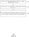
- Fig. 2 is a process flow diagram of an example method for generating a user interface based on rules.
- the method 200 can be implemented with any suitable computing device, such as the computing system 102 of Fig. 1 .
- a system analyzer 142 can detect a type of a system based on hardware components residing within the system or coupled to the system.
- the type of the system can include an augmented reality device, a tablet device, a mobile device, a phone device, a gaming console device, or a desktop device, among others.
- the system analyzer 142 can detect the type of the system based on any suitable hardware components such as a display screen, a processor, a graphics processor, a cellular radio, and the like.
- the system analyzer 142 can determine that a system that includes a cellular radio is a phone device.
- the system analyzer 142 can determine a type of the device based on a size of the display screen of the device. For example, devices that include a display screen that is smaller than a predetermined threshold size can be identified as mobile devices. In some embodiments, the system analyzer 142 can determine that devices that support three dimensional user interfaces are augmented reality devices and devices that connect to gaming controllers are gaming console devices. In some embodiments, the system analyzer 142 can detect a device type based on other hardware components such as power sources, graphics processors, memory devices, and the like.
- system analyzer 142 can use a combination of predetermined conditions, such as the presence of a specific combination of modules 122 used for a mobile device or a different combination of modules 122 used for a desktop device, as well as the heuristics called out here to make a final determination of the type and configuration of the current system.
- a user interface selector 144 can determine a user interface manager to execute based on the type of the system.
- the user interface managers (also referred to herein as composers) can generate a user interface based on the type of a system.
- a user interface may enable overlapping windows on desktop devices, but not on mobile devices.
- the user interface managers may include application switchers including a link to a digital assistant along with icons corresponding to applications that are being executed, among other features.
- the user interface selector 144 can determine the user interface manager to execute to produce a user experience corresponding to a device.
- each type of device is associated with a particular user interface manager.
- an augmented reality device may have a first user interface manager and a gaming console device may have a second user interface manager.
- each user interface manager can indicate how a user interface is to be generated for applications being executed.
- a user interface generator 146 can execute the user interface manager to generate a user interface for the system, wherein the type of the user interface manager comprises a plurality of rules to indicate a layout of the user interface.
- the plurality of rules can indicate how to display applications being executed and other visual elements such as an application launcher, an application switcher, and a window list, among others, which may or may not be an independent application or a collection of user manager rules defining how to show, for example, a clock.
- An application launcher as referred to herein, can include a list of executable applications installed on a system, a list of recently accessed applications installed on the system, recommended applications to be installed on the system, and the like.
- the application launcher can include commands that can access programs, documents, and settings. These commands can include a search function based on locally stored applications and files, a list of documents available locally on a device or on a remote server, a control panel to configure components of a device, power function commands to alter the power state of the device, and the like.
- An application switcher as referred to herein, can include a link to a digital assistant, a task view illustrating all open applications, a set of icons corresponding to applications being executed, and various icons corresponding to applications and hardware features that are enabled each time a device receives power.
- the plurality of rules can indicate an area of a screen that is to be occupied by the application launcher, application switcher, and windows corresponding to applications that are being executed.
- the plurality of rules may not rely on pixel to pixel mappings by the applications being executed.
- user interface controls can be displayed in regions of a display screen based on the rules.
- a text field may be displayed in the center of an application and the location of the text field can be determined by the user interface generator 146 based on the plurality of rules.
- the location of the text field may depend upon whether application windows are overlapping one another, if more than one application window is visible, and the like.
- the location of user interface controls can also be adjusted based on a size and location of the application switcher.
- the application switcher can be displayed along the top, bottom, left side, or right side of a display screen.
- Each type of user interface manager can determine a location of application windows in relation to the location of the application switcher.
- the user interface generator 146 can display the user interface based on at least one display characteristic corresponding to the user interface manager.
- a user interface manager for gaming console devices may display applications in a full screen mode with no frame or adornments.
- the user interface manager 146 can also display an application switcher and desktop background.
- An application switcher as described in greater detail below, can include any number of icons corresponding to hardware control applications, executing application, digital assistants, and the like.
- the desktop background can include any suitable image, any number of links to locally stored files, links to directories, and the like.
- user interface concepts such as an application launcher, application switcher, window adornments, action centers, and other instances of user interface experiences mentioned herein are exemplary in nature.
- the plurality of rules presented to user interface generator 146 may create any user experience desired. There is also no limitations on the complexity of such rules. Some rules may simply indicate when and how an element of text is to be placed on the screen while other rules may define a multi-stage 3D experience with numerous potential outcomes.
- the process flow diagram of Fig. 2 is intended to indicate that the blocks of the method 200 are to be executed in a particular order.
- the blocks of the method 200 can be executed in any suitable order and any suitable number of the blocks of the method 200 can be included. Further, any number of additional blocks may be included within the method 200, depending on the specific application.
- the method 200 can include detecting that a system or device shifts from a first type of a device to a second type of device. For example, a mobile device may be inserted into a docking station that provides a larger display screen.
- the user interface generator 146 can detect a change to the available hardware resources of the mobile device and generate a desktop based user interface to replace a mobile device based user interface.
- the method 200 can also include detecting that an external monitor is coupled to a mobile device or a phone device.
- the user interface manager 146 can generate a separate user interface based on a desktop user interface if the size of the external monitor exceeds a predetermined threshold.
- the method 200 can include generating a user interface that includes at least one active application and at least one visible application.
- An active application can indicate an application accepting user input, while a visible application can be displayed but not accepting user input.
- the method 200 can also include executing a second user interface manager, wherein the second user interface manager is to execute an action center and a notifications detector application.
- the method 200 can also include managing at least two subordinate user interface managers, wherein each of the at least two subordinate user interface managers is to execute a separate application.
- the method 200 can also include detecting that an input device is coupled to a system and generating a new user interface manager based on the input device, wherein the input device is a gaming controller and the new user interface manager is to provide a gaming console user interface. Additionally, the method 200 can include storing a state of the user interface in response to transitioning from the user interface manager to the new user interface manager.
- a user interface manager can be implemented with various configurations.
- the user interface manager can be implemented with an executed application that includes visuals and adornments, a persistent user interface in a main thread of a user interface manager, a persistent user interface in a non-main thread of a user interface manager, as a hosted shell experience for out of process applications, or a recursively composed user interface manager, among others.
- the various configurations of the user interface manager are illustrated and described below in relation to Fig. 3 .
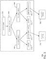
- Fig. 3 is a block diagram of an example system that can generate a user interface for multiple user applications based on rules.
- Rules may be represented as high level concepts, such as display a block of text in the center of a region, or lowlevel concepts, such as those which require the rule author to determine the size of a region and mathematically center the text in the region.
- the user interface manager 300 can be executed with any suitable number of applications and software components.
- the user interface 300 manager can use Windows.UI.Composition or Extensible Application Markup Language (XAML) to imperatively or declaratively describe various rules which results in the creation of a user interface or shell starting at the root of the visual tree 302.
- XAML Extensible Application Markup Language
- user interface manager 300 may use any available technologies such as HTML in any of its various forms, OpenGL, Vulkan, Collada, or other existing user experience frameworks to define and manage the way in which user experience rules are converted to generate visual trees which describe on-screen experiences.
- the user interface manager 300 is also enabled to use these rules for composing visuals that are running outside of a process such as in other shell component applications or other the top level visuals of other application experiences.
- the user interface manager 300 can implement a specific user interface or shell experience by composing different smaller common components of the shell together in a way that reflects the overall shell experience. Also, the user interface manager 300 can configure a component's properties to realize a particular shell experience based on system analyzer 142.
- the user interface manager 300 can communicate with an underlying shell or user interface through a set of private application programming interfaces (APIs). These private APIs can allow the user interface manager to execute instructions corresponding to shell tasks associated with a shell.
- the shell task can include application activation and lifetime management, application or process locks, application resizing, application visibility changes, shutdown, and other shell features.
- the user interface manager 300 can also reflect a current state of a shell. The state of a shell can include the active view, running applications, current screen resolution and other shell state information.
- the user interface manager 300 can present the visuals of user applications to the user in additional to the shell experience. These applications can paint into a buffer (represented by a DCOMP visual surface or other similar technology) using the framework of the application's choice. In such examples, the buffer does not paint to screen directly and by default does not get on screen by itself. Rather, the user interface manager 300 can select the visuals for an application and display the application. In some embodiments, the user interface manager 300 can also add adornments, such as a title bar or drop shadow, on the top level visual of a user application. In some embodiments, the user interface manager 300 can also indicate any per application window content such as splash screens, among others.
- a buffer represented by a DCOMP visual surface or other similar technology
- a user interface manager 300 can communicate with a Windows List Control 304 function to provide a list of applications being executed on a system. Based on the user interface rules applied by user interface manager 300 each application in the list can be associated with a windows user interface control 306 or 308, which is also associated with a title bar 310 or 312 and a windows content host 314 or 316. The resulting user interface rules enable, for example, a window that is dragged to have the contents of the window also moved because the render transform for the move is applied to the child visual that happens to be the application's composition visual in a coordinated fashion. In the example of Fig. 3 , windows control host 314 displays an active user application 1 318 and windows control host 316 display a visible user application 2 320.
- Differences in visual representation between title bar 310 wrapping active application 318 and title bar 312 wrapping active application 320 are also indicated and managed through user interface rules processed by user interface generator 146.
- the user interface manager 300 can indicate if user application 1 318 and user application 2 320 can be overlapped, viewed side by side, resized, and the like.
- Fig. 3 is not intended to indicate that the user interface manager 300 is to create a visual representation containing all of the components shown in Fig. 3 . Rather, the user interface manager 300 can cause the visual tree to include fewer or additional components not illustrated in Fig. 3 (e.g., additional applications, additional modules, additional experiences, etc.).
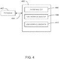
- Fig. 4 is a block diagram of an example computer-readable storage media that can generate a user interface based on rules.
- the tangible, computer-readable storage media 400 may be accessed by a processor 402 over a computer bus 404. Furthermore, the tangible, computer-readable storage media 400 may include code to direct the processor 402 to perform the steps of the current method.
- the tangible computer-readable storage media 400 can include a system analyzer 406 that can detect a type of the system based on hardware and software components residing within the system.
- a user interface selector 408 can determine a user interface manager to execute based on the type of the system.
- a user interface generator 410 can execute the type of the user interface manager to generate a user interface for the system, wherein the type of the user interface manager comprises a plurality of rules to indicate a layout of the user interface.
- Fig. 5 is a block diagram of an example system for hosting user interface managers within a user interface manager.
- multiple user interface managers can be active at the same time and a system can morph between one or more of these user interface managers based on a state of the system and any number of rules.
- user interface managers can also be expressed in a simultaneous fashion, where multiple user interface managers are used in an independent way from one another. For example, a user interface for a device, such as a desktop PC, can morph to and from a tablet mode in a more efficient way.
- there is a global data model and a view model which understands and represents the elements being hosted in these experiences so that morphing is possible.
- a user interface host 500 can include rules such as product policy, and display and input policy 502 which can be used and interpreted by system analyzer 142 to determine a user interface manager to execute based on the type of system.
- the user interface host 500 can generate a visual tree 504 based on the product policy, display and input policy 502, and a state of a system.
- the visual tree 504 can include a root visual 506, user interface manager 1 508, user interface manager 2 510, and user interface manager 3 512.
- either user interface manager 1 508, user interface manager 2 510, or user interface manager 3 512 can be used to generate a user interface.
- user interface host 500 in figure 5 could represent a user interface host capable of presenting a user experience for a 2-in-1 portable computer. With a keyboard attached and active such a device behaves as a traditional laptop computer while with the keyboard removed the same device behaves more like a tablet computer.
- User interface host 500 uses system analyzer 406 to determine, among other things, when the keyboard is active or not. When User interface host 500 determines that the keyboard is active, it enables user interface manager 508.
- user interface manager 508 uses a plurality of rules in conjunction with user interface generator 410 to create a user experience which is appropriate for the user of a laptop computer. Such a user experience might include the use of overlapping windows for applications and user experiences which are optimized for mouse and keyboard usage among others.
- a user may do an action, such as detaching the keyboard, which causes system analyzer 406 to recognize that the keyboard is no longer active and user interface host 500 to determine that user interface manager 508 is no longer the correct experience to present to the user.
- user interface host 500 is enabled to cause user manager 508 to morph into user manager 510 which expresses a more tablet appropriate experience without impacting the user's ability to interact with the system.
- a tablet mode experience might replace the use of overlapping windows with a single full screen experience and user experiences which are optimized for touch usage among others.
- the process of morphing implies a seamless visual transition from one visual state of the system to another visual state using animation techniques and the like all while maintaining the ability of componentized visual elements such as title bar 310 or title bar 312 to support user input or do other tasks.
- this is achieved by having a centralized repository of information about the state of top level application visuals and other key visual components being presented throughout the system. This state preserved in this repository is independent of the rules and information used by each user interface manager to present these top level application visuals and other elements. Part of this state information in the repository is the association which exists between these visual elements and the user interface manager responsible for presenting them on screen.
- system analyzer 406 determines that the keyboard is no longer active and user interface host 500 responds by indicating that user interface manager 508 is to be replaced by user interface manager 510 the combination of information in this state repository and the loose coupling with user interface managers enable a quick and efficient replacement of user interface manager 508 with user interface manage 510.
- user interface generator 410 to interpret rules for animation and other behaviors at the same time provides a seamless transition of visuals and input from user interface manager 508 to user interface manager 510. It is appreciated that the methods and technologies called out here, such as the use of a common state repository for top level application visuals, are examples only and other embodiments may employ different approaches and combinations of hardware and software to achieve similar effects.
- user interface host 500 is enabled to create environments in which user interface managers are recursively embedded in each other.
- a traditional desktop computer which uses overlapping windows and includes a virtual desktop paradigm.
- Virtual desktops are a feature of many modern operating system user experiences which enables a user to create alternate desktops. The user is then able to switch between each of these desktops as a way to segregate different tasks. For example, a user may use one desktop for managing work related applications related to one project, a different desktop for managing work related applications for a separate project, and a different desktop for managing applications related to their personal life.
- Often such virtual desktop implementations allow for applying different customizations, such as a desktop background, on each virtual desktop.
- each instance of user interface manager 508, 510, and 512 is configured by user interface generator 410 with the appropriate set of rules to express a desktop experience. Assume that user interface manager 508 is then associated by the user with applications for the first work project, user interface manager 510 for the second work project, and user interface manager 512 for the third work project. Using techniques like those described in the previous example it is possible for user interface host 500 to use user feedback provided through system analyzer 406 to present the appropriate user interface managers 508, 510, or 512 depending on user choice. This functionality matches virtual desktop implementations.
- user interface manager 510 is an independent instance of the desktop experience, which itself is separated from user interface manager 508 and 512, allows for the user to simultaneously present any combination of user interface managers 508, 510, and 512 to the user.
- This enables, for example, a user to show and interact with both user interface manager 508 and user interface manager 510 simultaneously allowing the user to interact with both desktop experiences at the same time.
- One such embodiment of this experience allows for hosting user manager 510 inside of user manager 508 as a separate overlapped window.
- user interface manager 512 containing personal information could be hosted in a window by user experience manager 508.
- connection between root visual 506 as shown in figure 5 to user interface manager 510 and 512 would be removed and they would instead be connected as children of user interface manager 508.
- Using techniques as previously described user interface manager 510 and 512 would be enabled to properly morph their experience in a seamless fashion as they are hosted under user interface manager 508.
- system 400 may be enabled, through system analyzer and other appropriate hardware and software affordances, to create different associations of input devices 126 and output devices 130 as described in figure 1 to create a partitioning of the system. For example, consider a desktop computer with four input devices 126 - two mice and two keyboards or the like - and two output devices 130 - a computer monitor or the like - attached to it. Using these hardware and software affordances the system is able to be partitioned into two distinct collections of mouse, keyboard, and monitor. Each of these partitions would be visible to user interface host 500 through system analyzer 406. Using the affordances provided by user interface host 500 it is possible to associate a separate user experience with each of these partitions. For example, user interface host 500 may associate user interface 508 with the first partition and user interface 510 with the second partition thus allowing one or more users to interact with the user interfaces simultaneously.
- an environment can be created in which user interface host 500 can show user experience 508 and 510 simultaneously in these configurations, which may not be different than that required to show user experience 508 and 510 in a mutually exclusive fashion.
- user interface managers and user interface generator the burden of creating and managing the complexity of these scenarios has been significantly simplified effectively allowing for the re-use of an entire system user experience as a component in a much larger overall experience.
- examples used herein are not limiting on any form or function.
- user interface managers 508, 510, and 512 may represent different distinct experiences such as a desktop experience, a gaming console experience, and a media room entertainment experience instead of all being the same experience.
- the user interface can include at least one active application and at least one visible application.
- the type of the system comprises a mobile system, a gaming console system, an augmented reality system, a tablet system, or a desktop system.
- the plurality of instructions can cause the processor to display the user interface based on at least one display characteristic corresponding to the user interface manager.
- the user interface manager is to manage at least two subordinate user interface managers, wherein each of the at least two subordinate user interface managers is to execute a separate application.
- the user interface manager is also to manage a shell application that is to support experiences.
- the user interface manager is also to manage a shell experience host that is to support experiences.
- the plurality of instructions can cause the processor to detect an input device is coupled to the system and generate a new user interface manager based on the input device.
- the input device is a gaming controller and the new user interface manager is to provide a gaming console user interface.
- the plurality of instructions can cause the processor to store a state of the user interface in response to transitioning from the user interface manager to the new user interface manager.
- the terms (including a reference to a "means") used to describe such components are intended to correspond, unless otherwise indicated, to any component which performs the specified function of the described component, e.g., a functional equivalent, even though not structurally equivalent to the disclosed structure, which performs the function in the herein illustrated exemplary aspects of the claimed subject matter.
- the innovation includes a system as well as a computer-readable storage media having computer-executable instructions for performing the acts and events of the various methods of the claimed subject matter.
- one or more components may be combined into a single component providing aggregate functionality or divided into several separate sub-components, and any one or more middle layers, such as a management layer, may be provided to communicatively couple to such sub-components in order to provide integrated functionality.
- middle layers such as a management layer
- Any components described herein may also interact with one or more other components not specifically described herein but generally known by those of skill in the art.
Landscapes
- Engineering & Computer Science (AREA)
- Theoretical Computer Science (AREA)
- Software Systems (AREA)
- General Engineering & Computer Science (AREA)
- Human Computer Interaction (AREA)
- Physics & Mathematics (AREA)
- General Physics & Mathematics (AREA)
- User Interface Of Digital Computer (AREA)
- Electrophonic Musical Instruments (AREA)
- Stored Programmes (AREA)
Applications Claiming Priority (1)
| Application Number | Priority Date | Filing Date | Title |
|---|---|---|---|
| PCT/US2017/038032 WO2018231259A1 (en) | 2017-06-16 | 2017-06-16 | Rules based user interface generation |
Publications (2)
| Publication Number | Publication Date |
|---|---|
| EP3612929A1 EP3612929A1 (en) | 2020-02-26 |
| EP3612929B1 true EP3612929B1 (en) | 2022-08-24 |
Family
ID=59270139
Family Applications (1)
| Application Number | Title | Priority Date | Filing Date |
|---|---|---|---|
| EP17734911.5A Active EP3612929B1 (en) | 2017-06-16 | 2017-06-16 | Rules based user interface generation |
Country Status (13)
| Country | Link |
|---|---|
| US (2) | US11809217B2 (pt) |
| EP (1) | EP3612929B1 (pt) |
| JP (1) | JP7007401B2 (pt) |
| KR (1) | KR102378953B1 (pt) |
| CN (1) | CN110785740A (pt) |
| AU (1) | AU2017418322B2 (pt) |
| BR (1) | BR112019026121A2 (pt) |
| CA (1) | CA3063675A1 (pt) |
| CO (1) | CO2019013990A2 (pt) |
| IL (1) | IL271255B2 (pt) |
| PH (1) | PH12019550259A1 (pt) |
| RU (1) | RU2020100889A (pt) |
| WO (1) | WO2018231259A1 (pt) |
Families Citing this family (1)
| Publication number | Priority date | Publication date | Assignee | Title |
|---|---|---|---|---|
| CN111596985B (zh) * | 2020-04-24 | 2023-03-14 | 腾讯科技(深圳)有限公司 | 多媒体会议场景下的界面显示方法、装置、终端及介质 |
Family Cites Families (59)
| Publication number | Priority date | Publication date | Assignee | Title |
|---|---|---|---|---|
| US5675755A (en) * | 1995-06-07 | 1997-10-07 | Sony Corporation | Window system preventing overlap of multiple always-visible windows |
| US6282646B1 (en) * | 1998-05-08 | 2001-08-28 | Apple Computer, Inc. | System for real-time adaptation to changes in display configuration |
| US6188399B1 (en) * | 1998-05-08 | 2001-02-13 | Apple Computer, Inc. | Multiple theme engine graphical user interface architecture |
| US6753885B2 (en) * | 2000-04-06 | 2004-06-22 | Microsoft Corporation | System and theme file format for creating visual styles |
| US7137066B2 (en) * | 2000-04-06 | 2006-11-14 | Microsoft Corporation | Binary cache file format for themeing the visual appearance of a computer system |
| US7013297B2 (en) | 2001-02-27 | 2006-03-14 | Microsoft Corporation | Expert system for generating user interfaces |
| US7246326B2 (en) * | 2001-06-25 | 2007-07-17 | Siemens Medical Solutions Health Services Corporation | System and procedure for providing a user interface display |
| US7392483B2 (en) * | 2001-09-28 | 2008-06-24 | Ntt Docomo, Inc, | Transformation of platform specific graphical user interface widgets migrated between heterogeneous device platforms |
| US7234111B2 (en) * | 2001-09-28 | 2007-06-19 | Ntt Docomo, Inc. | Dynamic adaptation of GUI presentations to heterogeneous device platforms |
| US7895522B2 (en) * | 2001-09-28 | 2011-02-22 | Ntt Docomo, Inc. | Layout of platform specific graphical user interface widgets migrated between heterogeneous device platforms |
| US7952569B2 (en) * | 2002-08-08 | 2011-05-31 | Hewlett-Packard Development Company, L.P. | System and method of switching between multiple viewing modes in a multi-head computer system |
| CA2509862A1 (en) * | 2002-12-13 | 2004-07-01 | Wagerworks, Inc. | Flexible user interface |
| US7417644B2 (en) * | 2003-05-12 | 2008-08-26 | Microsoft Corporation | Dynamic pluggable user interface layout |
| US8196044B2 (en) | 2004-01-05 | 2012-06-05 | Microsoft Corporation | Configuration of user interfaces |
| US8130237B2 (en) * | 2004-06-24 | 2012-03-06 | Apple Inc. | Resolution independent user interface design |
| US7730484B2 (en) * | 2004-11-12 | 2010-06-01 | Opera Software Asa | Method and device for providing interfaces that are tailored to specific devices |
| US7450084B2 (en) * | 2004-12-17 | 2008-11-11 | Microsoft Corporation | System and method for managing computer monitor configurations |
| US7907966B1 (en) | 2005-07-19 | 2011-03-15 | Aol Inc. | System and method for cross-platform applications on a wireless phone |
| CN100419848C (zh) * | 2005-09-28 | 2008-09-17 | 联想(北京)有限公司 | 一种多显示器系统及其自动设置显示模式的方法 |
| US20070079236A1 (en) * | 2005-10-04 | 2007-04-05 | Microsoft Corporation | Multi-form design with harmonic composition for dynamically aggregated documents |
| US7707514B2 (en) * | 2005-11-18 | 2010-04-27 | Apple Inc. | Management of user interface elements in a display environment |
| EP1884871A1 (en) | 2006-07-26 | 2008-02-06 | Research In Motion Limited | System and method for adaptive theming of a mobile device |
| US8869027B2 (en) * | 2006-08-04 | 2014-10-21 | Apple Inc. | Management and generation of dashboards |
| EP2124142A4 (en) | 2007-02-16 | 2010-08-04 | Sharp Kk | USER INTERFACE GENERATOR, INFORMATION ENTITY DEVICE, USER INTERFACE MANAGEMENT PROGRAM, RECORDING MEDIA, AND USER SURFACE MANUFACTURING METHOD |
| WO2008131417A1 (en) * | 2007-04-23 | 2008-10-30 | Snac, Inc. | Mobile widget dashboard |
| US8954871B2 (en) * | 2007-07-18 | 2015-02-10 | Apple Inc. | User-centric widgets and dashboards |
| US20090150773A1 (en) * | 2007-12-05 | 2009-06-11 | Sun Microsystems, Inc. | Dynamic product configuration user interface |
| TW201044255A (en) | 2009-06-12 | 2010-12-16 | Acer Inc | Electronic device, computer-executable system, and application program display control method thereof |
| US20110153612A1 (en) | 2009-12-17 | 2011-06-23 | Infosys Technologies Limited | System and method for providing customized applications on different devices |
| US20140026086A1 (en) * | 2010-04-28 | 2014-01-23 | Adobe Systems Incorporated | Methods and Systems for Cross-Platform Computing Applications Featuring Adaptable User Interfaces |
| US20120017172A1 (en) * | 2010-07-15 | 2012-01-19 | Microsoft Corporation | Display-agnostic user interface for mobile devices |
| US20120054634A1 (en) | 2010-08-27 | 2012-03-01 | Sony Corporation | Apparatus for and method of creating a customized ui based on user preference data |
| US9621567B2 (en) | 2010-11-29 | 2017-04-11 | Biocatch Ltd. | Device, system, and method of detecting hardware components |
| US9043714B1 (en) * | 2011-01-07 | 2015-05-26 | Google Inc. | Adaptive user interface for widescreen devices |
| US20120284631A1 (en) | 2011-05-02 | 2012-11-08 | German Lancioni | Methods to adapt user interfaces and input controls |
| US9013510B2 (en) | 2011-07-29 | 2015-04-21 | Google Inc. | Systems and methods for rendering user interface elements in accordance with a device type |
| US20140040819A1 (en) * | 2011-09-09 | 2014-02-06 | Adobe Systems Incorporated | Methods and systems for managing the presentation of windows on a display device |
| CA2792662C (en) * | 2011-10-18 | 2017-11-14 | Research In Motion Limited | Method of rendering a user interface |
| US8856729B2 (en) * | 2011-12-23 | 2014-10-07 | Airstrip Ip Holdings, Llc | Systems and methods for developing multi-platform applications for computing devices |
| US20130191775A1 (en) * | 2012-01-25 | 2013-07-25 | Richard James Lawson | Adjustable user interface |
| US20170168782A1 (en) * | 2012-05-28 | 2017-06-15 | Ian Boyd | System and method for creating a universally compatible application development system |
| US9239668B2 (en) * | 2012-06-29 | 2016-01-19 | Intel Corporation | Provision of a user interface based on user interaction with a computing device |
| US9107076B1 (en) | 2012-07-27 | 2015-08-11 | Sprint Communications Company L.P. | Data fraud detection via device type identification |
| US9053243B2 (en) * | 2012-10-10 | 2015-06-09 | Google Inc. | Unidirectional and bidirectional communication between a host device and a peripheral device |
| US20140157183A1 (en) * | 2012-11-30 | 2014-06-05 | John Gordon Dorsay | System and method for the selection, layout, and control of one or more hosted interactive computer application programs using a lightweight supervisor computer application program |
| US9239713B1 (en) | 2013-03-06 | 2016-01-19 | MobileForce Software, Inc. | Platform independent rendering for native mobile applications |
| US9747005B1 (en) * | 2013-03-11 | 2017-08-29 | Workday, Inc. | Adaptive user interface |
| US20140325374A1 (en) | 2013-04-30 | 2014-10-30 | Microsoft Corporation | Cross-device user interface selection |
| US9626146B2 (en) * | 2013-07-24 | 2017-04-18 | Kabushiki Kaisha Toshiba | Electronic apparatus, configuration setting method for adjusting display size and storage medium |
| KR20150014319A (ko) * | 2013-07-29 | 2015-02-06 | 삼성전자주식회사 | 사용자 인터페이스 화면을 제공하는 모바일 디바이스와 화상형성장치, 및 모바일 디바이스 및 화상형성장치에서 사용자 인터페이스 화면을 제공하는 방법 |
| US9513763B1 (en) * | 2014-03-20 | 2016-12-06 | Amazon Technologies, Inc. | Adaptive user interfaces |
| US9471201B1 (en) | 2014-05-20 | 2016-10-18 | Google Inc. | Laptop-to-tablet mode adaptation |
| US10120659B2 (en) * | 2014-05-30 | 2018-11-06 | Apple Inc. | Adaptive user interfaces |
| US20160132301A1 (en) * | 2014-11-06 | 2016-05-12 | Microsoft Technology Licensing, Llc | Programmatic user interface generation based on display size |
| CN107211040B (zh) | 2014-11-24 | 2019-07-02 | 思研室公司 | 动态并自动创建用户界面的方法 |
| US10042655B2 (en) * | 2015-01-21 | 2018-08-07 | Microsoft Technology Licensing, Llc. | Adaptable user interface display |
| US10552183B2 (en) * | 2016-05-27 | 2020-02-04 | Microsoft Technology Licensing, Llc | Tailoring user interface presentations based on user state |
| US10025548B2 (en) * | 2016-08-09 | 2018-07-17 | International Business Machines Corporation | Automated display configuration |
| US10620792B2 (en) * | 2017-03-10 | 2020-04-14 | Jonathan Glickman | Computing device with an appropriate adaptable user hardware interface |
-
2017
- 2017-06-16 EP EP17734911.5A patent/EP3612929B1/en active Active
- 2017-06-16 CA CA3063675A patent/CA3063675A1/en active Pending
- 2017-06-16 WO PCT/US2017/038032 patent/WO2018231259A1/en unknown
- 2017-06-16 BR BR112019026121-4A patent/BR112019026121A2/pt unknown
- 2017-06-16 AU AU2017418322A patent/AU2017418322B2/en active Active
- 2017-06-16 CN CN201780091953.5A patent/CN110785740A/zh active Pending
- 2017-06-16 RU RU2020100889A patent/RU2020100889A/ru unknown
- 2017-06-16 JP JP2019561853A patent/JP7007401B2/ja active Active
- 2017-06-16 IL IL271255A patent/IL271255B2/en unknown
- 2017-06-16 KR KR1020207000328A patent/KR102378953B1/ko active IP Right Grant
- 2017-06-16 US US16/613,613 patent/US11809217B2/en active Active
-
2019
- 2019-11-28 PH PH12019550259A patent/PH12019550259A1/en unknown
- 2019-12-11 CO CONC2019/0013990A patent/CO2019013990A2/es unknown
-
2023
- 2023-09-08 US US18/463,806 patent/US20240143350A1/en active Pending
Also Published As
| Publication number | Publication date |
|---|---|
| BR112019026121A2 (pt) | 2020-07-07 |
| CO2019013990A2 (es) | 2020-01-17 |
| IL271255B (en) | 2022-11-01 |
| US20210286632A1 (en) | 2021-09-16 |
| IL271255A (en) | 2020-01-30 |
| IL271255B2 (en) | 2023-03-01 |
| WO2018231259A1 (en) | 2018-12-20 |
| JP2020529055A (ja) | 2020-10-01 |
| EP3612929A1 (en) | 2020-02-26 |
| KR102378953B1 (ko) | 2022-03-24 |
| KR20200018574A (ko) | 2020-02-19 |
| AU2017418322B2 (en) | 2022-06-30 |
| RU2020100889A (ru) | 2021-07-16 |
| CN110785740A (zh) | 2020-02-11 |
| CA3063675A1 (en) | 2018-12-20 |
| US20240143350A1 (en) | 2024-05-02 |
| AU2017418322A1 (en) | 2019-11-28 |
| JP7007401B2 (ja) | 2022-01-24 |
| US11809217B2 (en) | 2023-11-07 |
| PH12019550259A1 (en) | 2020-07-13 |
Similar Documents
| Publication | Publication Date | Title |
|---|---|---|
| JP6659644B2 (ja) | 応用素子の代替的グラフィック表示の事前の生成による入力に対する低レイテンシの視覚的応答およびグラフィック処理ユニットの入力処理 | |
| US10417991B2 (en) | Multi-display device user interface modification | |
| EP3499351A1 (en) | Controlling a device using a radial graphical user interface | |
| US11989571B2 (en) | Generating user interface containers | |
| US20240143350A1 (en) | Rules Based User Interface Generation | |
| US20220221970A1 (en) | User interface modification | |
| US11237699B2 (en) | Proximal menu generation | |
| CN110908675B (zh) | 运行环境获取方法、装置和电子设备 | |
| US20190056857A1 (en) | Resizing an active region of a user interface | |
| EP3635527B1 (en) | Magnified input panels | |
| US10664557B2 (en) | Dial control for addition and reversal operations | |
| US10678517B1 (en) | User interface synthesis based upon extracted presentation document graphical features |
Legal Events
| Date | Code | Title | Description |
|---|---|---|---|
| STAA | Information on the status of an ep patent application or granted ep patent |
Free format text: STATUS: UNKNOWN |
|
| STAA | Information on the status of an ep patent application or granted ep patent |
Free format text: STATUS: THE INTERNATIONAL PUBLICATION HAS BEEN MADE |
|
| PUAI | Public reference made under article 153(3) epc to a published international application that has entered the european phase |
Free format text: ORIGINAL CODE: 0009012 |
|
| STAA | Information on the status of an ep patent application or granted ep patent |
Free format text: STATUS: REQUEST FOR EXAMINATION WAS MADE |
|
| 17P | Request for examination filed |
Effective date: 20191120 |
|
| AK | Designated contracting states |
Kind code of ref document: A1 Designated state(s): AL AT BE BG CH CY CZ DE DK EE ES FI FR GB GR HR HU IE IS IT LI LT LU LV MC MK MT NL NO PL PT RO RS SE SI SK SM TR |
|
| AX | Request for extension of the european patent |
Extension state: BA ME |
|
| DAV | Request for validation of the european patent (deleted) | ||
| DAX | Request for extension of the european patent (deleted) | ||
| STAA | Information on the status of an ep patent application or granted ep patent |
Free format text: STATUS: EXAMINATION IS IN PROGRESS |
|
| 17Q | First examination report despatched |
Effective date: 20210817 |
|
| STAA | Information on the status of an ep patent application or granted ep patent |
Free format text: STATUS: EXAMINATION IS IN PROGRESS |
|
| RAP3 | Party data changed (applicant data changed or rights of an application transferred) |
Owner name: MICROSOFT TECHNOLOGY LICENSING, LLC |
|
| GRAP | Despatch of communication of intention to grant a patent |
Free format text: ORIGINAL CODE: EPIDOSNIGR1 |
|
| STAA | Information on the status of an ep patent application or granted ep patent |
Free format text: STATUS: GRANT OF PATENT IS INTENDED |
|
| INTG | Intention to grant announced |
Effective date: 20220325 |
|
| GRAS | Grant fee paid |
Free format text: ORIGINAL CODE: EPIDOSNIGR3 |
|
| GRAA | (expected) grant |
Free format text: ORIGINAL CODE: 0009210 |
|
| STAA | Information on the status of an ep patent application or granted ep patent |
Free format text: STATUS: THE PATENT HAS BEEN GRANTED |
|
| AK | Designated contracting states |
Kind code of ref document: B1 Designated state(s): AL AT BE BG CH CY CZ DE DK EE ES FI FR GB GR HR HU IE IS IT LI LT LU LV MC MK MT NL NO PL PT RO RS SE SI SK SM TR |
|
| REG | Reference to a national code |
Ref country code: CH Ref legal event code: EP |
|
| REG | Reference to a national code |
Ref country code: DE Ref legal event code: R096 Ref document number: 602017060990 Country of ref document: DE |
|
| REG | Reference to a national code |
Ref country code: IE Ref legal event code: FG4D |
|
| REG | Reference to a national code |
Ref country code: AT Ref legal event code: REF Ref document number: 1514121 Country of ref document: AT Kind code of ref document: T Effective date: 20220915 |
|
| REG | Reference to a national code |
Ref country code: NL Ref legal event code: FP |
|
| REG | Reference to a national code |
Ref country code: LT Ref legal event code: MG9D |
|
| PG25 | Lapsed in a contracting state [announced via postgrant information from national office to epo] |
Ref country code: SE Free format text: LAPSE BECAUSE OF FAILURE TO SUBMIT A TRANSLATION OF THE DESCRIPTION OR TO PAY THE FEE WITHIN THE PRESCRIBED TIME-LIMIT Effective date: 20220824 Ref country code: RS Free format text: LAPSE BECAUSE OF FAILURE TO SUBMIT A TRANSLATION OF THE DESCRIPTION OR TO PAY THE FEE WITHIN THE PRESCRIBED TIME-LIMIT Effective date: 20220824 Ref country code: PT Free format text: LAPSE BECAUSE OF FAILURE TO SUBMIT A TRANSLATION OF THE DESCRIPTION OR TO PAY THE FEE WITHIN THE PRESCRIBED TIME-LIMIT Effective date: 20221226 Ref country code: NO Free format text: LAPSE BECAUSE OF FAILURE TO SUBMIT A TRANSLATION OF THE DESCRIPTION OR TO PAY THE FEE WITHIN THE PRESCRIBED TIME-LIMIT Effective date: 20221124 Ref country code: LV Free format text: LAPSE BECAUSE OF FAILURE TO SUBMIT A TRANSLATION OF THE DESCRIPTION OR TO PAY THE FEE WITHIN THE PRESCRIBED TIME-LIMIT Effective date: 20220824 Ref country code: LT Free format text: LAPSE BECAUSE OF FAILURE TO SUBMIT A TRANSLATION OF THE DESCRIPTION OR TO PAY THE FEE WITHIN THE PRESCRIBED TIME-LIMIT Effective date: 20220824 Ref country code: FI Free format text: LAPSE BECAUSE OF FAILURE TO SUBMIT A TRANSLATION OF THE DESCRIPTION OR TO PAY THE FEE WITHIN THE PRESCRIBED TIME-LIMIT Effective date: 20220824 |
|
| REG | Reference to a national code |
Ref country code: AT Ref legal event code: MK05 Ref document number: 1514121 Country of ref document: AT Kind code of ref document: T Effective date: 20220824 |
|
| PG25 | Lapsed in a contracting state [announced via postgrant information from national office to epo] |
Ref country code: PL Free format text: LAPSE BECAUSE OF FAILURE TO SUBMIT A TRANSLATION OF THE DESCRIPTION OR TO PAY THE FEE WITHIN THE PRESCRIBED TIME-LIMIT Effective date: 20220824 Ref country code: IS Free format text: LAPSE BECAUSE OF FAILURE TO SUBMIT A TRANSLATION OF THE DESCRIPTION OR TO PAY THE FEE WITHIN THE PRESCRIBED TIME-LIMIT Effective date: 20221224 Ref country code: HR Free format text: LAPSE BECAUSE OF FAILURE TO SUBMIT A TRANSLATION OF THE DESCRIPTION OR TO PAY THE FEE WITHIN THE PRESCRIBED TIME-LIMIT Effective date: 20220824 Ref country code: GR Free format text: LAPSE BECAUSE OF FAILURE TO SUBMIT A TRANSLATION OF THE DESCRIPTION OR TO PAY THE FEE WITHIN THE PRESCRIBED TIME-LIMIT Effective date: 20221125 |
|
| PG25 | Lapsed in a contracting state [announced via postgrant information from national office to epo] |
Ref country code: SM Free format text: LAPSE BECAUSE OF FAILURE TO SUBMIT A TRANSLATION OF THE DESCRIPTION OR TO PAY THE FEE WITHIN THE PRESCRIBED TIME-LIMIT Effective date: 20220824 Ref country code: RO Free format text: LAPSE BECAUSE OF FAILURE TO SUBMIT A TRANSLATION OF THE DESCRIPTION OR TO PAY THE FEE WITHIN THE PRESCRIBED TIME-LIMIT Effective date: 20220824 Ref country code: ES Free format text: LAPSE BECAUSE OF FAILURE TO SUBMIT A TRANSLATION OF THE DESCRIPTION OR TO PAY THE FEE WITHIN THE PRESCRIBED TIME-LIMIT Effective date: 20220824 Ref country code: DK Free format text: LAPSE BECAUSE OF FAILURE TO SUBMIT A TRANSLATION OF THE DESCRIPTION OR TO PAY THE FEE WITHIN THE PRESCRIBED TIME-LIMIT Effective date: 20220824 Ref country code: CZ Free format text: LAPSE BECAUSE OF FAILURE TO SUBMIT A TRANSLATION OF THE DESCRIPTION OR TO PAY THE FEE WITHIN THE PRESCRIBED TIME-LIMIT Effective date: 20220824 Ref country code: AT Free format text: LAPSE BECAUSE OF FAILURE TO SUBMIT A TRANSLATION OF THE DESCRIPTION OR TO PAY THE FEE WITHIN THE PRESCRIBED TIME-LIMIT Effective date: 20220824 |
|
| REG | Reference to a national code |
Ref country code: DE Ref legal event code: R097 Ref document number: 602017060990 Country of ref document: DE |
|
| PG25 | Lapsed in a contracting state [announced via postgrant information from national office to epo] |
Ref country code: SK Free format text: LAPSE BECAUSE OF FAILURE TO SUBMIT A TRANSLATION OF THE DESCRIPTION OR TO PAY THE FEE WITHIN THE PRESCRIBED TIME-LIMIT Effective date: 20220824 Ref country code: EE Free format text: LAPSE BECAUSE OF FAILURE TO SUBMIT A TRANSLATION OF THE DESCRIPTION OR TO PAY THE FEE WITHIN THE PRESCRIBED TIME-LIMIT Effective date: 20220824 |
|
| P01 | Opt-out of the competence of the unified patent court (upc) registered |
Effective date: 20230523 |
|
| PG25 | Lapsed in a contracting state [announced via postgrant information from national office to epo] |
Ref country code: AL Free format text: LAPSE BECAUSE OF FAILURE TO SUBMIT A TRANSLATION OF THE DESCRIPTION OR TO PAY THE FEE WITHIN THE PRESCRIBED TIME-LIMIT Effective date: 20220824 |
|
| PLBE | No opposition filed within time limit |
Free format text: ORIGINAL CODE: 0009261 |
|
| STAA | Information on the status of an ep patent application or granted ep patent |
Free format text: STATUS: NO OPPOSITION FILED WITHIN TIME LIMIT |
|
| PGFP | Annual fee paid to national office [announced via postgrant information from national office to epo] |
Ref country code: NL Payment date: 20230523 Year of fee payment: 7 Ref country code: FR Payment date: 20230523 Year of fee payment: 7 Ref country code: DE Payment date: 20230523 Year of fee payment: 7 |
|
| 26N | No opposition filed |
Effective date: 20230525 |
|
| PG25 | Lapsed in a contracting state [announced via postgrant information from national office to epo] |
Ref country code: SI Free format text: LAPSE BECAUSE OF FAILURE TO SUBMIT A TRANSLATION OF THE DESCRIPTION OR TO PAY THE FEE WITHIN THE PRESCRIBED TIME-LIMIT Effective date: 20220824 |
|
| PGFP | Annual fee paid to national office [announced via postgrant information from national office to epo] |
Ref country code: GB Payment date: 20230523 Year of fee payment: 7 |
|
| PG25 | Lapsed in a contracting state [announced via postgrant information from national office to epo] |
Ref country code: MC Free format text: LAPSE BECAUSE OF FAILURE TO SUBMIT A TRANSLATION OF THE DESCRIPTION OR TO PAY THE FEE WITHIN THE PRESCRIBED TIME-LIMIT Effective date: 20220824 |
|
| PG25 | Lapsed in a contracting state [announced via postgrant information from national office to epo] |
Ref country code: MC Free format text: LAPSE BECAUSE OF FAILURE TO SUBMIT A TRANSLATION OF THE DESCRIPTION OR TO PAY THE FEE WITHIN THE PRESCRIBED TIME-LIMIT Effective date: 20220824 |
|
| REG | Reference to a national code |
Ref country code: CH Ref legal event code: PL |
|
| REG | Reference to a national code |
Ref country code: BE Ref legal event code: MM Effective date: 20230630 |
|
| PG25 | Lapsed in a contracting state [announced via postgrant information from national office to epo] |
Ref country code: LU Free format text: LAPSE BECAUSE OF NON-PAYMENT OF DUE FEES Effective date: 20230616 |
|
| REG | Reference to a national code |
Ref country code: IE Ref legal event code: MM4A |
|
| PG25 | Lapsed in a contracting state [announced via postgrant information from national office to epo] |
Ref country code: LU Free format text: LAPSE BECAUSE OF NON-PAYMENT OF DUE FEES Effective date: 20230616 |
|
| PG25 | Lapsed in a contracting state [announced via postgrant information from national office to epo] |
Ref country code: IE Free format text: LAPSE BECAUSE OF NON-PAYMENT OF DUE FEES Effective date: 20230616 |
|
| PG25 | Lapsed in a contracting state [announced via postgrant information from national office to epo] |
Ref country code: IE Free format text: LAPSE BECAUSE OF NON-PAYMENT OF DUE FEES Effective date: 20230616 Ref country code: CH Free format text: LAPSE BECAUSE OF NON-PAYMENT OF DUE FEES Effective date: 20230630 |