EP3611548A1 - Projection system and projection-type image display apparatus - Google Patents
Projection system and projection-type image display apparatus Download PDFInfo
- Publication number
- EP3611548A1 EP3611548A1 EP19188317.2A EP19188317A EP3611548A1 EP 3611548 A1 EP3611548 A1 EP 3611548A1 EP 19188317 A EP19188317 A EP 19188317A EP 3611548 A1 EP3611548 A1 EP 3611548A1
- Authority
- EP
- European Patent Office
- Prior art keywords
- lens
- axis
- optical system
- projection system
- imaginary
- Prior art date
- Legal status (The legal status is an assumption and is not a legal conclusion. Google has not performed a legal analysis and makes no representation as to the accuracy of the status listed.)
- Granted
Links
- 230000003287 optical effect Effects 0.000 claims abstract description 243
- 230000015572 biosynthetic process Effects 0.000 claims abstract description 73
- 230000004907 flux Effects 0.000 claims description 114
- 230000002093 peripheral effect Effects 0.000 claims description 46
- 230000014509 gene expression Effects 0.000 claims description 23
- 230000009467 reduction Effects 0.000 claims description 5
- 238000010586 diagram Methods 0.000 description 40
- 239000004973 liquid crystal related substance Substances 0.000 description 38
- 210000001747 pupil Anatomy 0.000 description 23
- 230000000052 comparative effect Effects 0.000 description 16
- 239000011347 resin Substances 0.000 description 14
- 229920005989 resin Polymers 0.000 description 14
- 230000007423 decrease Effects 0.000 description 11
- 230000010354 integration Effects 0.000 description 10
- 230000001629 suppression Effects 0.000 description 9
- 239000011521 glass Substances 0.000 description 7
- 230000004075 alteration Effects 0.000 description 5
- 230000000694 effects Effects 0.000 description 5
- 239000011248 coating agent Substances 0.000 description 4
- 238000000576 coating method Methods 0.000 description 4
- 238000001746 injection moulding Methods 0.000 description 4
- 230000008901 benefit Effects 0.000 description 2
- 238000003384 imaging method Methods 0.000 description 2
- 230000010287 polarization Effects 0.000 description 2
- 241001270131 Agaricus moelleri Species 0.000 description 1
- 230000009471 action Effects 0.000 description 1
- 230000031700 light absorption Effects 0.000 description 1
- 239000000463 material Substances 0.000 description 1
- QSHDDOUJBYECFT-UHFFFAOYSA-N mercury Chemical compound [Hg] QSHDDOUJBYECFT-UHFFFAOYSA-N 0.000 description 1
- 229910052753 mercury Inorganic materials 0.000 description 1
- 238000011144 upstream manufacturing Methods 0.000 description 1
Images


Classifications
-
- G—PHYSICS
- G03—PHOTOGRAPHY; CINEMATOGRAPHY; ANALOGOUS TECHNIQUES USING WAVES OTHER THAN OPTICAL WAVES; ELECTROGRAPHY; HOLOGRAPHY
- G03B—APPARATUS OR ARRANGEMENTS FOR TAKING PHOTOGRAPHS OR FOR PROJECTING OR VIEWING THEM; APPARATUS OR ARRANGEMENTS EMPLOYING ANALOGOUS TECHNIQUES USING WAVES OTHER THAN OPTICAL WAVES; ACCESSORIES THEREFOR
- G03B21/00—Projectors or projection-type viewers; Accessories therefor
- G03B21/14—Details
- G03B21/28—Reflectors in projection beam
-
- G—PHYSICS
- G02—OPTICS
- G02B—OPTICAL ELEMENTS, SYSTEMS OR APPARATUS
- G02B13/00—Optical objectives specially designed for the purposes specified below
- G02B13/16—Optical objectives specially designed for the purposes specified below for use in conjunction with image converters or intensifiers, or for use with projectors, e.g. objectives for projection TV
-
- G—PHYSICS
- G02—OPTICS
- G02B—OPTICAL ELEMENTS, SYSTEMS OR APPARATUS
- G02B17/00—Systems with reflecting surfaces, with or without refracting elements
- G02B17/08—Catadioptric systems
- G02B17/0856—Catadioptric systems comprising a refractive element with a reflective surface, the reflection taking place inside the element, e.g. Mangin mirrors
- G02B17/086—Catadioptric systems comprising a refractive element with a reflective surface, the reflection taking place inside the element, e.g. Mangin mirrors wherein the system is made of a single block of optical material, e.g. solid catadioptric systems
-
- G—PHYSICS
- G02—OPTICS
- G02B—OPTICAL ELEMENTS, SYSTEMS OR APPARATUS
- G02B13/00—Optical objectives specially designed for the purposes specified below
- G02B13/18—Optical objectives specially designed for the purposes specified below with lenses having one or more non-spherical faces, e.g. for reducing geometrical aberration
-
- G—PHYSICS
- G03—PHOTOGRAPHY; CINEMATOGRAPHY; ANALOGOUS TECHNIQUES USING WAVES OTHER THAN OPTICAL WAVES; ELECTROGRAPHY; HOLOGRAPHY
- G03B—APPARATUS OR ARRANGEMENTS FOR TAKING PHOTOGRAPHS OR FOR PROJECTING OR VIEWING THEM; APPARATUS OR ARRANGEMENTS EMPLOYING ANALOGOUS TECHNIQUES USING WAVES OTHER THAN OPTICAL WAVES; ACCESSORIES THEREFOR
- G03B21/00—Projectors or projection-type viewers; Accessories therefor
- G03B21/14—Details
- G03B21/147—Optical correction of image distortions, e.g. keystone
Landscapes
- Physics & Mathematics (AREA)
- General Physics & Mathematics (AREA)
- Optics & Photonics (AREA)
- Lenses (AREA)
- Projection Apparatus (AREA)
Abstract
Description
- The present application is based on, and claims priority from
JP Application Serial Number 2018-141034, filed July 27, 2018 2019-105945, filed June 6 2019 - The present disclosure relates to a projection system having a concave reflective surface on the magnifying side of an intermediate image, and to a projection-type image display apparatus including the projection system.
-
JP-A-2010-20344 JP-A-2010-20344 -
JP-A-2010-20344 - In the projection system described in
JP-A-2010-20344 - The size of the intermediate image increases as the intermediate image inclines. When the size of the intermediate image increases, it is necessary to increase the size of the reflective surface located at the magnifying side of the intermediate image. Therefore, in a projection system having only a concave reflective surface on the magnifying side of the intermediate image, shorting the projection distance causes an increase in the size of the reflective surface.
- An advantage of some aspects of the present disclosure is to provide a projection system capable of suppressing an increase in size of a concave reflective surface disposed on the magnifying side of an intermediate image even in the case of a short projection distance. Another advantage of some aspects of the present disclosure is to provide a projection-type image display apparatus including the projection system.
- An aspect of the present disclosure is directed to a projection system including a first optical system and a second optical system sequentially arranged from a demagnifying side toward a magnifying side, the projection system forming an intermediate image in a position between a demagnifying-side image formation plane and a magnifying-side image formation plane of the projection system. The second optical system is a lens. The lens has a first transmissive surface, a reflective surface, and a second transmissive surface sequentially arranged from the demagnifying side toward the magnifying side. Three axes perpendicular to one another are called axes X, Y, and Z, with an axis-Z direction being a direction in which the first transmissive surface and the reflective surface are arranged, an upper side being one side of the axis Y, a lower side being another side of the axis Y, and a plane YZ being a plane perpendicular to the axis X and containing the axes Y and Z . The first transmissive surface and the reflective surface are located at the lower side of an imaginary axis extending in the axis-Z direction. The second transmissive surface is located at the upper side of the imaginary axis. The reflective surface has a concave shape. The second transmissive surface has a convex shape protruding toward the magnifying side. An imaginary line that connects an upper intersection to a lower intersection inclines with respect to an imaginary vertical line perpendicular to the imaginary axis in the plane YZ, the upper intersection being an intersection where an upper peripheral light ray of an upper-end light flux that is a light ray passing through an axis-Y-direction upper end of an effective range of the second transmissive surface and an upper peripheral light ray of a lower-end light flux that is a light ray passing through an axis-Y-direction lower end of the effective range intersect with each other in the plane YZ, and the lower intersection being an intersection where a lower peripheral light ray of the upper-end light flux and a lower peripheral light ray of the lower-end light flux intersect with each other in the plane YZ. The intermediate image is located in the lens between the first transmissive surface and the reflective surface.
- In the aspect of the present disclosure, the first optical system may be a refractive optical system.
- In the aspect of the present disclosure, the imaginary axis may coincide with an optical axis of the first optical system.
- In the aspect of the present disclosure, principal rays between the first optical system and the second optical system may approach each other toward the second optical system.
- In the aspect of the present disclosure, any of the first transmissive surface, the reflective surface, and the second transmissive surface may be an aspheric surface.
- In the aspect of the present disclosure, the first transmissive surface may be an aspheric surface.
- In the aspect of the present disclosure, the intermediate image may have a shape that allows reduction in trapezoidal distortion of a final image formed in the magnifying-side image formation plane.
- In the aspect of the present disclosure, the first transmissive surface, the reflective surface, and the second transmissive surface may form a coaxial optical system having surfaces rotationally symmetric with respect to the imaginary axis, and the imaginary axis may be a design reference axis.
- In the aspect of the present disclosure, the projection system may satisfy a conditional expression below,

- In the aspect of the present disclosure, the projection system may satisfy a conditional expression (2) below,

- A projection-type image display apparatus according to another aspect of the present disclosure includes any of the projection systems described above and a display that displays a projection image in the demagnifying-side image formation plane of the projection system.
- In the aspect of the present disclosure, the display may form the projection image on the upper side of the optical axis of the first optical system.
-
-
FIG. 1 is a schematic configuration diagram of a projection-type image display apparatus including a projection system according to an embodiment of the present disclosure. -
FIG. 2 is a light ray diagram of a projection system according toEmbodiment 1. -
FIG. 3 is a partially enlarged view of a portion A inFIG. 2 . -
FIG. 4 is a partially enlarged view of a portion B inFIG. 2 . -
FIG. 5 is a light ray diagram of the projection system according toEmbodiment 1 enlarged. -
FIG. 6 is a light ray diagram with a portion including a second optical system of the projection system according toEmbodiment 1 enlarged. -
FIG. 7 describes the magnification of the projection system in a case where the second optical system has only a reflective surface. -
FIG. 8 describes the magnification of the projection system in a case where the second optical system has the reflective surface and a second transmissive surface which is disposed on the magnifying side of the reflective surface. -
FIG. 9 shows an MTF of the projection system according toEmbodiment 1 on the magnifying side. -
FIG. 10 is a spot diagram showing spots produced by the projection system according to Embodiment 1. -
FIG. 11 is a light ray diagram of a projection system according to Comparative Embodiment. -
FIG. 12 is a light ray diagram of the projection system according to Comparative Embodiment enlarged. -
FIG. 13 shows an MTF of the projection system according to Comparative Embodiment on the magnifying side. -
FIG. 14 is a spot diagram showing spots produced by the projection system according to Comparative Embodiment. -
FIG. 15 is a light ray diagram of a projection system according toEmbodiment 2. -
FIG. 16 is a light ray diagram of the projection system according toEmbodiment 2. -
FIG. 17 is a light ray diagram with a portion including a second optical system of the projection system according to Embodiment 2 enlarged. -
FIG. 18 shows the MTF of the projection system according toEmbodiment 2 on the magnifying side. -
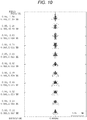
FIG. 19 is a spot diagram showing spots produced by the projection system according to Embodiment 2. -
FIG. 20 is a light ray diagram of a projection system according toEmbodiment 3. -
FIG. 21 is a light ray diagram of the projection system according toEmbodiment 3 enlarged. -
FIG. 22 is a light ray diagram with a portion including a second optical system of the projection system according to Embodiment 3 enlarged. -
FIG. 23 shows an MTF of the projection system according toEmbodiment 3 on the magnifying side. -
FIG. 24 is a spot diagram showing spots produced by the projection system according toEmbodiment 3. -
FIG. 25 is a light ray diagram of a projection system according toEmbodiment 4. -
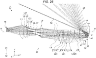
FIG. 26 is a light ray diagram of the projection system according toEmbodiment 4 enlarged. -
FIG. 27 is a light ray diagram with a portion including a second optical system of the projection system according toEmbodiment 4 enlarged. -
FIG. 28 shows an MTF of the projection system according toEmbodiment 4 on the magnifying side. -
FIG. 29 is a spot diagram showing spots produced by the projection system according toEmbodiment 4. - A projection system according to an embodiment of the present disclosure and a projection-type image display apparatus including the projection system will be described below in detail with reference to the drawings.
-
FIG. 1 is a schematic configuration diagram of the projection-type image display apparatus including the projection system according to the embodiment of the present disclosure. A projection-typeimage display apparatus 1 includes animage formation section 2, which generates image light to be projected on a screen S, aprojection system 3, which enlarges and projects the image light, and acontroller 4, which controls the action of theimage formation section 2, as shown inFIG. 1 . - The
image formation section 2 includes alight source 10, a firstoptical integration lens 11, a secondoptical integration lens 12, apolarization converter 13, and a superimposinglens 14. Thelight source 10 is formed, for embodiment, of an ultrahigh-pressure mercury lamp, a solid-state light source, or any other light source. The firstoptical integration lens 11 and the secondoptical integration lens 12 each include a plurality of lens elements arranged in an array. The firstoptical integration lens 11 divides a light flux from thelight source 10 into a plurality of light fluxes. The lens elements of the firstoptical integration lens 11 focus the light flux from thelight source 10 in the vicinity of the lens elements of the secondoptical integration lens 12. - The
polarization converter 13 converts the light from the secondoptical integration lens 12 into predetermined linearly polarized light. The superimposinglens 14 superimposes images of each of the lens elements of the firstoptical integration lens 11 on one another on a display area of each ofliquid crystal panels optical integration lens 12. - The
image formation section 2 further includes a firstdichroic mirror 15, areflection mirror 16, afield lens 17R, and theliquid crystal panel 18R. The firstdichroic mirror 15 reflects R light, which is part of light rays incident via the superimposinglens 14, and transmits G light and B light, which are part of the light rays incident via the superimposinglens 14. The R light reflected off the firstdichroic mirror 15 travels via thereflection mirror 16 and thefield lens 17R and is incident on theliquid crystal panel 18R. Theliquid crystal panel 18R is an image display device. Theliquid crystal panel 18R modulates the R light in accordance with an image signal to form a red projection image. One of theliquid crystal panels - The
image formation section 2 further includes a seconddichroic mirror 21, afield lens 17G, and theliquid crystal panel 18G. The seconddichroic mirror 21 reflects the G light, which is part of the light rays from the firstdichroic mirror 15, and transmits B light, which is part of the light rays from the firstdichroic mirror 15. The G light reflected off the seconddichroic mirror 21 passes through thefield lens 17G and is incident on theliquid crystal panel 18G. Theliquid crystal panel 18G is an image display device. Theliquid crystal panel 18G modulates the G light in accordance with an image signal to form a green projection image. - The
image formation section 2 further includes arelay lens 22, areflection mirror 23, arelay lens 24, areflection mirror 25, afield lens 17B, and theliquid crystal panel 18B. The B light having passed through the seconddichroic mirror 21 travels via therelay lens 22, thereflection mirror 23, therelay lens 24, thereflection mirror 25, and thefield lens 17B and is incident on theliquid crystal panel 18B. Theliquid crystal panel 18B is an image display device. Theliquid crystal panel 18B modulates the B light in accordance with an image signal to form a blue projection image. - The
liquid crystal panels dichroic prism 19 in such a way that theliquid crystal panels dichroic prism 19. The crossdichroic prism 19, which is a prism for light combination, combines the light modulated by theliquid crystal panel 18R, the light modulated by theliquid crystal panel 18G, and the light modulated by theliquid crystal panel 18B with one another into image light. - The cross
dichroic prism 19 forms part of theprojection system 3. Theprojection system 3 enlarges and projects the combined image light from the cross dichroic prism 19 (projection images formed byliquid crystal panels - The
controller 4 includes animage processor 6, to which an external image signal, such as a video signal, is inputted, and adisplay driver 7, which drives theliquid crystal panels image processor 6. - The
image processor 6 converts the image signal inputted from an external apparatus into image signals each containing grayscales and other factors on a color basis. Thedisplay driver 7 operates theliquid crystal panels image processor 6. Theimage processor 6 thus displays projection images corresponding to the image signals on theliquid crystal panels - The
projection system 3 will next be described. In the following sections,Embodiments 1 to 4 will be described as configuration embodiments of theprojection system 3 incorporated in the projection-typeimage display apparatus 1. -
FIG. 2 is a light ray diagram of a projection system according toEmbodiment 1 of the present disclosure.FIG. 3 is a partially enlarged view of a portion A inFIG. 2 .FIG. 4 is a partially enlarged view of a portion B inFIG. 2 .FIG. 5 is a light ray diagram of the projection system according toEmbodiment 1 enlarged.FIG. 6 is a light ray diagram with a portion including a second optical system of the projection system according toEmbodiment 1 enlarged.FIG. 2 diagrammatically shows 11 light fluxes F1 to F11, which exit out of aprojection system 3A and reach the screen S . The light flux F1 is a light flux that reaches a lowest image height position. The light flux F11 is a light flux that reaches a highest image height position. The light fluxes F2 to F10 are light fluxes that reach height positions between the height position that the light flux F1 reaches and the height position that the light flux F11 reaches. - The
projection system 3A according to the present embodiment is formed of a firstoptical system 31 and a secondoptical system 32 sequentially arranged from the demagnifying side toward the magnifying side, as shown inFIG. 2 . Theprojection system 3A forms anintermediate image 33 in a position between the demagnifying-side image formation plane and the magnifying-side image formation plane of theprojection system 3A, as shown inFIG. 5 . - The first
optical system 31 is a refractive optical system including a plurality of lenses. In the present embodiment, the firstoptical system 31 includes 15 lenses. The secondoptical system 32 is formed of alens 35. Theliquid crystal panels image formation section 2 are disposed in the demagnifying-side image formation plane.FIGS. 2 and5 show theliquid crystal panel 18G, which is one of the threeliquid crystal panels liquid crystal panels optical system 31 in the demagnifying-side image formation plane. The screen S is disposed in the magnifying-side image formation plane. - The
intermediate image 33 is formed in the secondoptical system 32, that is, thelens 35. Theintermediate image 33 is formed on the other side of the optical axis N of the firstoptical system 31. A final image projected on the screen S has an oblong shape elongated in the lateral direction. In the present embodiment, the final image has an aspect ratio of 16:10. - The first
optical system 31 includes the crossdichroic prism 19 and a first lens L1 to a fifteenth lens L15, which form 15 lenses, as shown inFIG. 5 . The first lens L1 to the fifteenth lens L15 are arranged in the presented order from the demagnifying side toward the magnifying side. In the present embodiment, the second lens L2 and the third lens L3 are bonded to each other to form a first doublet L21. The fourth lens L4 and the fifth lens L5 are bonded to each other to form a second doublet L22. The eleventh lens L11 and the twelfth lens L12 are bonded to each other to form a third doublet L23. The thirteenth lens L13 and the fourteenth lens L14 are bonded to each other to form a fourth doublet L24. A stop O is disposed between the seventh lens L7 and the eighth lens L8. In the present embodiment, the sixth lens L6, the ninth lens L9, and the fifteenth lens L15 are three lenses that are each an aspheric lens having aspheric surfaces on both surfaces. - In the first
optical system 31, the fifteenth lens L15, which is located in a position closest to the magnifying side, has positive power. In the firstoptical system 31, a magnifying-side lens group LG25, which is located in a position closest to the secondoptical system 32, has positive power. The magnifying-side lens group LG25 is formed of three lenses arranged from the side facing the secondoptical system 32. That is, the thirteenth lens L13, the fourteenth lens L14, and the fifteenth lens L15 form the magnifying-side lens group LG25. Since the magnifying-side lens group LG25 has positive power in the firstoptical system 31, the principal rays between the firstoptical system 31 and the secondoptical system 32 approach each other toward the secondoptical system 32, as shown inFIG. 5 . - The
lens 35, which forms the secondoptical system 32, is made of resin. Thelens 35 has afirst transmissive surface 41, areflective surface 42, and asecond transmissive surface 43 sequentially arranged from the demagnifying side toward the magnifying side, as shown inFIG. 6 . In the case where thelens 35 is made of resin, thelens 35 can be manufactured in injection molding. Alens 35 having a complicated shape is therefore readily manufactured. - In the following description, three axes perpendicular to one another are called axes X, Y, and Z for convenience. A first direction in which the
first transmissive surface 41 and thereflective surface 42 are arranged is called an axis-Z direction. A second direction, which is called an axis-y direction, coincides with the vertical direction of the screen S. One side of the axis Y is called an upper side Y1, and the other side of the axis Y is called a lower side Y2. A first plane perpendicular to the axis X and containing the axes Y and Z is called a plane YZ.FIGS. 1 to 6 therefore each show the plane YZ. The optical axis N of the firstoptical system 31 extends in the axis-Z direction. Theimage formation section 2 forms a projection image on the upper side Y1 of the optical axis N of the firstoptical system 31. Theintermediate image 33 is formed on the lower side Y2 of the optical axis N of the firstoptical system 31. The lateral direction of the screen S coincides a third direction, which is called with the axis-X direction. In the following description, an imaginary axis M extending in the axis-Z direction is set in the plane YZ. The imaginary axis M is a reference axis used in the design of thelens 35. The imaginary axis M is perpendicular to the screen S, which is the magnifying-side image formation plane. The imaginary axis M is substantially perpendicular to the screen S in some cases. - The
first transmissive surface 41 and thereflective surface 42 are located at the lower side Y2 of the imaginary axis M. Thesecond transmissive surface 43 is located at the upper side Y1 of the imaginary axis M. Thereflective surface 42 has a concave shape. Thereflective surface 42 therefore has positive power. Thereflective surface 42 is provided by externally forming a reflective coating on thelens 35. Thesecond transmissive surface 43 has a convex shape protruding toward the magnifying side. Thesecond transmissive surface 43 therefore has positive power. Thefirst transmissive surface 41, thereflective surface 42, and thesecond transmissive surface 43 form a coaxial optical system having surfaces rotationally symmetric with respect to the imaginary axis M. Therefore, the imaginary axis M is the reference axis used in the design of thelens 35 and is the optical axis of thelens 35. In the present embodiment, the imaginary axis M coincides with the optical axis N of the firstoptical system 31. The imaginary axis M does not necessarily coincide with the optical axis N of the firstoptical system 31. - The upper and lower halves of the
lens 35 are each configured to be rotationally symmetric with respect to the imaginary axis M. That is, thefirst transmissive surface 41, thereflective surface 42, and thesecond transmissive surface 43 are so shaped that the cross-sectional shape in the plane YZ shown inFIG. 6 is rotated around the imaginary axis M over an angular range of 90° toward one side and the other side of the axis-X direction. In the present embodiment, thefirst transmissive surface 41, thereflective surface 42, and thesecond transmissive surface 43 are each an aspheric surface. - An imaginary line P can be specified in the
lens 35 of the secondoptical system 32, as shown inFIG. 6 . The imaginary line P connects anupper intersection 53 to alower intersection 54, theupper intersection 53 being an intersection where an upper peripherallight ray 51a of an upper-end light flux 51, where the upper-end light flux 51 is the light flux passing through the axis-Y-direction upper end of aneffective range 50 of thesecond transmissive surface 43, and an upper peripherallight ray 52a of a lower-end light flux 52, where the lower-end light flux 52 is the light flux passing through the axis-Y-direction lower end of theeffective range 50, intersect with each other in the plane YZ, and thelower intersection 54 being an intersection where a lower peripherallight ray 51b of the upper-end light flux 51 and a lower peripherallight ray 52b of the lower-end light flux 52 intersect with each other in the plane YZ. The imaginary line P inclines by 98.77° with respect to an imaginary vertical line V, which is perpendicular to the imaginary axis M in the plane YZ. Further, in thelens 35 of the secondoptical system 32, the upper peripherallight ray 51a of the upper-end light flux 51 travels from thesecond transmissive surface 43 toward thereflective surface 42, and the point where the upper peripherallight ray 51a intersects another light ray reflected off thereflective surface 42 for the first time is called a first intersection. Similarly, the lower peripherallight ray 52b of the lower-end light flux 52 travels from thesecond transmissive surface 43 toward thereflective surface 42, and the point where the lower peripherallight ray 52b intersects another light ray reflected off thereflective surface 42 for the first time is called a second intersection. Under the above definition, the line that connects the first intersection to the second intersection is named as apupil 44. In the present embodiment, thepupil 44 inclines by 103.315° with respect to the imaginary vertical line V in the plane YZ. - The
intermediate image 33 is an inverted final image turned upside down. Theintermediate image 33 is an image so distorted that an oblong final image is projected on the screen S, which is the magnifying-side image formation plane. More specifically, theintermediate image 33 has a shape that allows reduction in trapezoidal distortion of the final image formed on the screen S. That is, theintermediate image 33 has distortion opposite the trapezoidal distortion of the final image. Theintermediate image 33 is therefore so formed that the shortest edge thereof is the edge having the highest image height on the screen S. - Data on the lenses of the
projection system 3A are as follows: The surfaces of the lenses are numbered sequentially from the demagnifying side toward the magnifying side. A surface having a surface number with * is an aspheric surface. Thesurface number 1 represents the demagnifying-side surface of the crossdichroic prism 19, and thesurface number 2 represents the magnifying-side surface thereof. The fields labeled with the surface number 20 show dummy data. The row of the reference characters represents the reference characters of the lenses thereof. The reference characters given in the secondoptical system 32 are the reference characters of thefirst transmissive surface 41, thereflective surface 42, and thesecond transmissive surface 43. That is, thesurface number 31 represents thefirst transmissive surface 41 of thelens 35. Thesurface number 33 represents thereflective surface 42 of thelens 35. Thesurface number 35 represents thesecond transmissive surface 43 of thelens 35. Reference character r denotes the radius of curvature in millimeters. Reference character d denotes the on-axis inter-surface distance in millimeters. Reference character nd denotes the refractive index. Reference character vd denotes the Abbe number. Reference character Y denotes the effective radius in the axis-Y direction. Reference character X denotes the effective radius in the axis-X direction.Surface number Reference character r d nd vd Y X Object plane 0 9.39 1 0 25.91 1.516331 64.14 13.27 13.27 2 0 0.1 16.289 16.289 3 L1 56.80565 6.965816 1.646732 58.36 16.758 16.758 4 -42.68536 0.1995 16.795 16.795 5 L2 32.84132 9.903502 1.483259 59.69 15.087 15.087 6 L3 -33.73055 1.197 1.841678 29.18 14.07 14.07 7 599.36572 0.1995 13.431 13.431 8 L4 25.79278 10.192649 1.516331 64.14 12.589 12.589 9 L5 -20.37894 1.197 1.903658 31.32 11.379 11.379 10 21.51184 1.012845 10.637 0.637 *11 L6 14.98812 1.3965 1.437002 95.1 10.831 10.831 *12 15.82309 0.370963 10.927 10.927 13 L7 21.34706 5.192064 1.458241 77.43 11.381 11.381 14 -203.44571 11.28 11.28 Stop plane 0 3.49125 12 12 16 L8 27.16508 4.1895 1.846663 23.78 10.379 10.379 17 -90.48264 3.3915 10 10 *18 L9 127.94794 1.7955 1.787436 38.46 9.476 9.476 *19 24.80943 2.9925 9.581 9.581 20 dummy 0 1.662166 9.975 9.975 21 L10 -30.9257 11 1.846663 23.78 9.978 9.978 22 -37.46179 8.254402 13.744 13.744 23 L11 -96.87787 10 1.665537 43.64 17.097 17.097 24 L12 -20.35957 11 1.834105 30.43 17. 528 17.528 25 -43.79383 14.751624 23.012 23.012 26 L13 39.90785 16.825248 1.604992 61.79 30 30 27 L14 -209.92296 1.995 1.844769 25.57 29.686 29.686 28 85.46293 25.235494 27.781 27.781 *29 L15 -94.94674 11 1.531132 55.75 25.435 25.435 *30 52.35571 2.93364 24.657 24.657 *31 41 -48.1898 33.25 1.531132 55.75 24.603 24.603 32 0 0 1.531132 55.75 22.06 22.06 *33 42 -26.026 0 1.531132 55.75 21.22 21.22 34 0 -33.25 1.531132 55.75 41.157 41.157 *35 43 20.45512 -466.75 20.295 20.295 Image plane 0 0 1451.18 2 1451.182 - As shown in the lens data, the refractive index nd of the
lens 35 is 1.531132, and the Abbe number vd of thelens 35 is 55.75. The field of the on-axis inter-surface distance d labeled with thesurface number 35 shows the distance between the screen S and thesecond transmissive surface 43 of thelens 35. The field of the on-axis inter-surface distance d labeled with thesurface number 35 therefore shows the projection distance f of theprojection system 3A. In the present embodiment, f=466.75 mm. In the present embodiment, the effective radius of thereflective surface 42 is 21.22 mm in the axis-Y direction and 21.22 mm in the axis-X direction. - Aspheric data of the
surface number 11 are as follows.Conic constant -4.291852E-01 Fourth-order coefficient -2.147243E-04 Sixth-order coefficient 6.917248E-07 Eighth-order coefficient -6.424421E-10 Tenth- order coefficient 0 - Aspheric data of the
surface number 12 are as follows.Conic constant -2.985186E-01 Fourth-order coefficient -2.429582E-04 Sixth-order coefficient 6.907024E-07 Eighth-order coefficient -1.68077E-09 Tenth-order coefficient 5.472176E-13 - Aspheric data of the
surface number 18 are as follows.Conic constant -1E+00 Fourth-order coefficient -9.067839E-05 Sixth- order coefficient 0 Eighth- order coefficient 0 Tenth- order coefficient 0 - Aspheric data of the
surface number 19 are as follows.Conic constant -8.8E-01 Fourth-order coefficient -5.124337E-05 Sixth-order coefficient 8.250618E-08 Eighth-order coefficient -8.04982E-11 Tenth- order coefficient 0 - Aspheric data of the surface number 29 are as follows.
Conic constant -7.854261E+01 Fourth-order coefficient 1.117938E-05 Sixth-order coefficient -4.392964E-09 Eighth-order coefficient -1.552816E-11 Tenth-order coefficient -1.508818E-15 Twelfth-order coefficient 2.210216E-17 Fourteenth-order coefficient -8.140301E-21 - Aspheric data of the surface number 30 are as follows.
Conic constant 2.047967E+00 Fourth-order coefficient -3.292408E-05 Sixth-order coefficient 3.055446E-08 Eighth-order coefficient -2.077281E-11 Tenth-order coefficient 2.14935E-14 Twelfth-order coefficient -2.539946E-17 Fourteenth-order coefficient 2.403648E-20 - Aspheric data of the
surface number 31 are as follows.Conic constant 0 Fourth-order coefficient 1.258824E-05 Sixth-order coefficient 3.935005E-09 Eighth-order coefficient -1.154515E-11 Tenth-order coefficient 2.202788E-14 Twelfth- order coefficient 0 Fourteenth- order coefficient 0 - Aspheric data of the
surface number 33 are as follows.Conic constant -1E+00 Fourth-order coefficient 4.920678E-06 Sixth-order coefficient -5.820738E-09 Eighth-order coefficient 6.336457E-12 Tenth-order coefficient 1.339523E-14 Twelfth-order coefficient -3.33883E-17 Fourteenth-order coefficient 2.827146E-20 - Aspheric data of the
surface number 35 are as follows.Conic constant 0 Fourth-order coefficient -1.223012E-06 Sixth-order coefficient -3.111316E-08 Eighth-order coefficient 9.115488E-11 Tenth-order coefficient -8.917847E-14 Twelfth- order coefficient 0 Fourteenth- order coefficient 0 - In the
projection system 3A according to the present embodiment, thelens 35, which forms the secondoptical system 32, has thereflective surface 42 with concave shape and thesecond transmissive surface 43 with a convex shape protruding toward the magnifying side. The light fluxes reflected off thereflective surface 42 are refracted by thesecond transmissive surface 43. Therefore, the projection distance of theprojection system 3A is readily shortened, as compared with a case where the secondoptical system 32 has only thereflective surface 42. - Further, in the present embodiment, an increase in the size of the
reflective surface 42, which is disposed on the magnifying side of theintermediate image 33, can be suppressed even in the case of a short projection distance. - The effects described above will be described in detail with reference to
FIGS. 7 and8 .FIG. 7 describes the magnification of the projection system in the case where the secondoptical system 32 has only thereflective surface 42 on the magnifying side of theintermediate image 33.FIG. 8 describes the magnification of the projection system in the case where the secondoptical system 32 has thereflective surface 42 and thesecond transmissive surface 43 with the convex shape protruding toward the magnifying side on the magnifying side of theintermediate image 33. - In the case where the second
optical system 32 has only thereflective surface 42 on the magnifying side of theintermediate image 33, the magnification Q of the projection system is represented by the ratio of T to R, where T is a distance from thereflective surface 42 to the screen S, and R is a distance between theintermediate image 33 and thereflective surface 42 along the optical path of a specific part of the light ray from theintermediate image 33 to the screen S, as shown inFIG. 7 . That is, Q=T/R. Theintermediate image 33, which is conjugate with the screen S which corresponds to the magnifying-side image formation plane, greatly inclines so that the magnification Q of each of light fluxes is equal and has field curvature due to the inclination. The size of theintermediate image 33 increases as theintermediate image 33 inclines. When the size of theintermediate image 33 increases, it is necessary to increase the size of thereflective surface 42 located at the magnifying side of theintermediate image 33. Therefore, in the projection system having only the concavereflective surface 42 on the magnifying side of theintermediate image 33, shorting the projection distance causes an increase in the size of thereflective surface 42. The size of theintermediate image 33 increases as theintermediate image 33 inclines, as described above. This means that a wider distance between the firstoptical system 31 and the secondoptical system 32 is necessary, resulting in an increase in the overall length of theprojection system 3A. - In contrast, in the present embodiment, in which the second
optical system 32 has thesecond transmissive surface 43 with the convex shape protruding toward the magnifying side on the magnifying side of thereflective surface 42, an increase in the size of theintermediate image 33 can be suppressed. That is, in the present embodiment, the magnification Q of theprojection system 3A is represented by the ratio of T' to (R1+R2), where T' is a distance between thesecond transmissive surface 43 and the screen S, R1 is a distance between theintermediate image 33 and thereflective surface 42 along the optical path of a specific part of the light ray from theintermediate image 33 to the screen S ,and R2 is a distance between thereflective surface 42 and thesecond transmissive surface 43, as shown inFIG. 8 . That is, Q=T'/(R1+R2) . Theintermediate image 33, which is conjugate with the screen S which corresponds to the magnifying-side image formation plane, therefore does not greatly incline and has reduced field curvature. As a result, an increase in the size of theintermediate image 33 can be suppressed. An increase in the size of thereflective surface 42, which is located at the magnifying side of theintermediate image 33, can therefore be suppressed. Further, if the upper-end light flux 51 can be refracted inward when passing through thefirst transmissive surface 41, the size of thereflective surface 42 can be further reduced. Moreover, thesecond transmissive surface 43, which has positive power, causes the light flux to be convergent, whereby an increase in the size of thereflective surface 42 can be suppressed, as compared with the case where nosecond transmissive surface 43 is provided. - Further, in the present embodiment, the magnifying-side lens group LG25, which is located in a position closest to the magnifying side in the first
optical system 31, has positive power, as shown inFIG. 5 . The principal rays between the firstoptical system 31 and the secondoptical system 32 therefore approach each other toward the secondoptical system 32. Therefore, theintermediate image 33 is readily formed, and the size of theintermediate image 33 can be reduced. The size of thereflective surface 42, which is located at the magnifying side of theintermediate image 33, can therefore be further reduced. - Further, in the present embodiment, the
intermediate image 33 is located in thelens 35 between thefirst transmissive surface 41 and thereflective surface 42. The firstoptical system 31 can be closer to thelens 35 than in a case where theintermediate image 33 is formed on the demagnifying side of thefirst transmissive surface 41. The overall length of theprojection system 3A can therefore be shortened. - In the present embodiment, the first
optical system 31 includes three aspheric lenses. Further, thefirst transmissive surface 41, thereflective surface 42, and thesecond transmissive surface 43 of the secondoptical system 32 are each an aspheric surface. Aberrations produced by theprojection system 3A according to the present embodiment can therefore be suppressed. - Further, in the present embodiment, since the
first transmissive surface 41, which is adjacent to theintermediate image 33 on the demagnifying side, is an aspheric surface, aberrations produced in the position of theintermediate image 33 can be suppressed. Moreover, in the present embodiment, since the secondoptical system 32 has thesecond transmissive surface 43 with the convex shape protruding toward the magnifying side on the magnifying side of thereflective surface 42, theintermediate image 33 does not greatly incline along the imaginary axis M. In other words, in the present embodiment, theintermediate image 33 extends in the direction perpendicular to the imaginary axis M. Therefore, according to the present embodiment, thefirst transmissive surface 41 and theintermediate image 33 can readily approach each other in the axis-Z direction, whereby the aspheric surface can be disposed in a position close to theintermediate image 33. Aberrations produced in the position of theintermediate image 33 can therefore be efficiently corrected. - In the present embodiment, the
lens 35, which forms the secondoptical system 32, satisfies the following conditional expressions (1) to (4), as shown inFIG. 6 .


- θ: Inclination angle over which an end of the imaginary line P facing the
upper intersection 53 rotates counterclockwise relative to the imaginary vertical line V around the intersection of the imaginary vertical line V and the imaginary line P - η: Inclination angle over which an end of the
pupil 44 facing the first intersection rotates counterclockwise relative to the imaginary vertical line V around the intersection of the imaginary vertical line V and thepupil 44 - γ: Angle from the imaginary axis M to the lower peripheral
light ray 52b passing through theeffective range 50 of thesecond transmissive surface 43 and intersects the imaginary axis M - That is, in the present embodiment, the imaginary line P inclines by 98 . 77° with respect to the imaginary vertical line V. Therefore, θ=98.77°, which satisfies the conditional expressions (1) and (2) are satisfied. Further, in the present embodiment, the
pupil 44 of the lens inclines by 103.315° with respect to the imaginary vertical line V. Therefore, η=103.315°, which satisfies the conditional expressions (3) and (4). - In the present embodiment, in which the conditional expression (1) is satisfied, the imaginary line P inclines with respect to the imaginary vertical line V. In a case where θ=0°, the imaginary line P is perpendicular to the imaginary axis M. That is, the imaginary line P is perpendicular to the design reference axis. Further, in the present embodiment, in which the conditional expression (3) is satisfied, the
pupil 44 inclines with respect to the imaginary vertical line V. In a case where η=0°, thepupil 44 is perpendicular to the imaginary axis M. In a case where at least one of θ in the conditional expression (1) and η in the conditional expression (3) is greater than the upper limit, the lower-end light flux 52 is blocked. In the present embodiment, in which the conditional expressions (1) and (3) are satisfied, the lower-end light flux 52 passing through the lower end of theeffective range 50 of thesecond transmissive surface 43 is not blocked but reaches the screen S. - Further, since the
lens 35 according to the present embodiment satisfies the conditional expression (1), a decrease of brightness at the upper periphery of the screen S can be suppressed, as compared with a case where the imaginary line P is parallel to the imaginary vertical line V. - That is, in the case where the imaginary line P is perpendicular to the imaginary axis M, that is, θ=0°, a divergence angle θ0 of a light flux that reaches an upper portion of the screen S decreases as the angle of view on the magnifying side increases. The divergence angle θ0 is shown in
FIGS. 3 and4 . Further, the difference in the divergence angle θ0 between the light flux that reaches the upper portion of the screen S and a light flux that reaches a lower portion of the screen S increases. As a result, the amount of light at the upper periphery of the screen S is smaller than the amount of light at the lower periphery of the screen S. - On the other hand, in the present embodiment, in which the conditional expression (1) is satisfied, the imaginary line P inclines with respect to the imaginary vertical line V. As a result, the divergence angle θ0 of the light flux that reaches the upper portion of the screen S increases. The amount of light that reaches the upper portion of the screen S therefore increases. Further, when the divergence angle θ0 of the light flux that reaches the upper portion of the screen S increases, the difference in the divergence angle θ0 between the light flux that reaches the upper portion of the image formation plane and the light flux that reaches the lower portion of the image formation plane decreases. The situation in which the amount of light at the upper periphery of the screen S is smaller than the amount of light at the lower periphery of the screen S can therefore be suppressed.
- In addition to the above, since the
lens 35 according to the present embodiment satisfies the conditional expression (2), the divergence angle θ0 of the light flux that reaches the lower portion of the screen S decreases. The difference in the divergence angle θ0 between the light flux that reaches the upper portion of the screen S and the lightflux that reaches the lower portion of the screen S therefore decreases, whereby the difference in the amount of light between the upper portion and the lower portion of the screen S can be suppressed. -
FIG. 9 shows an MTF of theprojection system 3A on the magnifying side. The MTF was calculated under the following conditions: The image formation planes were divided along the axis Y; and the resultant halves were each divided into 11 areas. Light rays used in the calculation of the MTF are so weighted that the weighting ratio among light rays having a wavelength of 620 nm, light rays having a wavelength of 550 nm, and light rays having a wavelength of 470 nm is 2:7:1. The horizontal axis ofFIG. 9 , which shows the MTF, represents the spatial frequency. A spatial frequency of 0.24 cycles corresponds to a resolution of 16.7 µm. The vertical axis ofFIG. 9 represents a contrast reproduction ratio. In the present embodiment, a decrease in resolution is suppressed, as shown inFIG. 9 .FIG. 10 is a spot diagram showing spots produced by theprojection system 3A. In the present embodiment, variation in the size of the spots is suppressed, as shown inFIG. 10 . - The fact that the
projection system 3A can provide the effect of suppressing an increase in the size of the concavereflective surface 42 disposed on the magnifying side of theintermediate image 33 even in the case of a short projection distance will be shown below as compared with Comparative Embodiment. - Comparative Embodiment relates to a projection system in which the second optical system is formed only of a reflection mirror having a reflective surface.
FIG. 11 is a light ray diagram of the projection system according to Comparative Embodiment.FIG. 12 is a light ray diagram of the projection system according to Comparative Embodiment enlarged.FIG. 11 diagrammatically shows 11 light fluxes F1 to F11, which exit out of aprojection system 100 according to Comparative Embodiment and reach the screen S. The light flux F1 is a light flux that reaches the lowest image height position. The light flux F11 is a light flux that reaches the highest image height position. The light fluxes F2 to F10 are light fluxes that reach height positions between the height position that the light flux F1 reaches and the height position that the light flux F11 reaches. Theprojection system 100 according to Comparative Embodiment has a configuration corresponding to the projection system described inJP-A-2010-20344 projection system 100 according to Comparative Embodiment further has a configuration corresponding to theprojection system 3A in the embodiment described above, and the corresponding components have the same reference characters in the following description. - The
projection system 100 according to the present embodiment is formed of the firstoptical system 31 and the secondoptical system 32 sequentially arranged from the demagnifying side toward the magnifying side, as shown inFIG. 11 . Theprojection system 100 forms theintermediate image 33 in a position between the demagnifying-side image formation plane and the magnifying-side image formation plane, as shown inFIG. 12 . The firstoptical system 31 is a refractive optical system including a plurality of lenses. The secondoptical system 32 is areflection mirror 101 having a reflective surface. Theliquid crystal panels image formation section 2 are disposed in the demagnifying-side image formation plane.FIGS. 11 and12 show theliquid crystal panel 18G, which is one of the threeliquid crystal panels liquid crystal panels optical system 31 in the demagnifying-side image formation plane. The screen S is disposed in the magnifying-side image formation plane. Theintermediate image 33 is formed on the other side of the optical axis N of the firstoptical system 31. A final image projected on the screen S has an oblong shape elongated in the lateral direction. In the present embodiment, the final image has the aspect ratio of 16:10. - The first
optical system 31 includes the crossdichroic prism 19 and the first lens L1 to the fifteenth lens L15, which form 15 lenses, as shown inFIG. 12 . The first lens L1 to the fifteenth lens L15 are arranged in the presented order from the demagnifying side toward the magnifying side. In the present embodiment, the second lens L2 and the third lens L3 are bonded to each other to form the first doublet L21. The fourth lens L4 and the fifth lens L5 are bonded to each other to form the second doublet L22. The eleventh lens L11 and the twelfth lens L12 are bonded to each other to form the third doublet L23. The stop O is disposed between the seventh lens L7 and the eighth lens L8. In the present embodiment, the sixth lens L6, the ninth lens L9, and the fifteenth lens L15 are three lenses that are each an aspheric lens having aspheric surfaces on both surfaces. - In the first
optical system 31, the fifteenth lens L15, which is located in a position closest to the magnifying side, has negative power. The principal rays between the firstoptical system 31 and the secondoptical system 32 separate away from each other toward the secondoptical system 32. - The second
optical system 32 is formed of thereflection mirror 101 having thereflective surface 42. Thereflective surface 42 is located at the lower side Y2 of the optical axis N of the firstoptical system 31. Thereflective surface 42 is so shaped that the cross-sectional shape in the plane YZ shown inFIG. 12 is rotated around the optical axis N over the angular range of 90° toward one side and the other side of the axis-X direction. Thereflective surface 42 is an aspheric surface. - The
intermediate image 33 is formed in a position between the fifteenth lens L15 of the firstoptical system 31 and thereflection mirror 101 of the secondoptical system 32. Theintermediate image 33, which is conjugate with the screen S which corresponds to the magnifying-side image formation plane, greatly inclines so that the magnification Q of each of light fluxes is equal, as shown inFIG. 12 . Theintermediate image 33 is a conjugate image that is an inverted final image turned upside down. Theintermediate image 33 is so distorted that an oblong final image is projected on the screen S, which is the magnifying-side image formation plane. More specifically, theintermediate image 33 has a shape that allows reduction in trapezoidal distortion of the final image formed on the screen S. That is, theintermediate image 33 has distortion opposite the trapezoidal distortion of the final image. Theintermediate image 33 is therefore so formed that the shortest edge thereof is the edge having the highest image height on the screen S. - Data on the lenses of the
projection system 100 are as follows: The surfaces of the lenses are numbered sequentially from the demagnifying side toward the magnifying side. A surface having a surface number with * is an aspheric surface. Thesurface number 1 represents the demagnifying-side surface of the crossdichroic prism 19, and thesurface number 2 represents the magnifying-side surface thereof. The fields labeled with the surface number 20 show dummy data. The reference characters given in the firstoptical system 31 are the reference characters of the lenses thereof. The row of the reference character represents the reference character of thereflective surface 42. That is, thesurface number 32 represents thereflective surface 42 of thereflection mirror 101. Reference character r denotes the radius of curvature in millimeters. Reference character d denotes the on-axis inter-surface distance in millimeters. Reference character nd denotes the refractive index. Reference character vd denotes the Abbe number. Reference character Y denotes the effective radius in the axis-Y direction. Reference character X denotes the effective radius in the axis-X direction.Surface number Reference character r d nd vd Y X Object plane 0 9.5 1 0 25.91 1.516331 64.14 13.149 13.149 2 0 0 15.92 15.92 3 L1 28.94031 9.6 1.497 81.55 16.8 16.8 4 -72.35054 0.2 16.597 16.597 5 L2 28.00787 7.6 1.497 81.55 14.95 14.95 6 L3 -80.72822 1.2 1.805181 25.43 14.201 14.201 7 84.18233 0.2 13.279 13.279 8 L4 23.1621 10.5 1.516331 64.14 12.332 12.332 9 L5 -18.39049 1.2 1.903658 31.32 10.829 10.829 10 49.86134 0.2 10.088 10.088 *11 L6 22.23222 1.4 1.589131 61.15 10.088 10.088 *12 14.51177 0.5 9.871 9.871 13 L7 18.70105 4 1.487491 70.24 9.984 9.984 14 85.77957 2.5 9.744 9.744 Stop plane 0 2.657363 9.434 9.434 16 L8 26.25511 4.2 1.84666 23.78 9.973 9.973 17 -72.32644 2.804685 9.8 9.8 *18 L9 -285.96073 1.8 1.743198 49.3 9.312 9.312 *19 20.09443 3 9.563 9.563 20 dummy 0 11.16296 10 10 21 L10 294.94797 3.8 1.761821 26.52 16.702 16.702 22 -185.55163 0.2 17.394 17.394 23 L11 88.77106 11.7 1.654115 39.68 18.691 18.691 24 L12 -32.58663 2 1.805181 25.43 19.198 19.198 25 -207.71339 7.258462 20.588 20.588 26 L13 47.46195 11 1.581439 40.75 24.7 24.7 27 -286.50997 1.90653 24.527 24.527 28 L14 -162.79029 2 1.805181 25.43 24.367 24.367 29 86.54168 13.837579 24.298 24.298 *30 L15 278 2.8 1.531132 55.75 26.772 26.772 *31 32.7897 112.362421 1 28.077 28.077 *32 42 -53.40115 -501 59.723 59.723 33 0 0 1450.989 1450.989 Image plane 0 0 1450.989 1450.989 - As shown in the lens data, the field of the on-axis inter-surface distance d labeled with the
surface number 32 shows the distance between the screen S and thereflective surface 42. The field of the on-axis inter-surface distance d labeled with thesurface number 32 therefore shows the projection distance f of theprojection system 100. In the present embodiment, f=501 mm. In the present embodiment, the effective radius of thereflective surface 42 is 59.723 mm in the axis-Y direction and 59.723 mm in the axis-X direction. - Aspheric data of the
surface number 11 are as follows.Conic constant 1.891766E+00 Fourth-order coefficient -3.21888E-04 Sixth-order coefficient 1.748382E-06 Eighth-order coefficient -4.334786E-09 Tenth- order coefficient 0 - Aspheric data of the
surface number 12 are as follows.Conic constant -1.715462E+00 Fourth-order coefficient -2.456905E-04 Sixth-order coefficient 2.077486E-06 Eighth-order coefficient -8.095391E-09 Tenth-order coefficient 1.652912E-11 - Aspheric data of the
surface number 18 are as follows.Conic constant -1E+00 Fourth-order coefficient -9E-05 Sixth- order coefficient 0 Eighth- order coefficient 0 Tenth- order coefficient 0 - Aspheric data of the
surface number 19 are as follows.Conic constant -5.793922E-01 Fourth-order coefficient -5.29339E-05 Sixth-order coefficient 1.037748E-07 Eighth-order coefficient -1.806724E-10 Tenth- order coefficient 0 - Aspheric data of the surface number 30 are as follows.
Conic constant 9E+01 Fourth-order coefficient -6.930833E-06 Sixth-order coefficient 2.131125E-08 Eighth-order coefficient -4.144247E-11 Tenth-order coefficient 3.842719E-14 Twelfth-order coefficient -1.672012E-17 - Aspheric data of the
surface number 31 are as follows.Conic constant 0 Fourth-order coefficient -2.83341E-05 Sixth-order coefficient 3.95412E-08 Eighth-order coefficient -6.268725E-11 Tenth-order coefficient 5.533984E-14 Twelfth-order coefficient -2.65766E-17 Fourteenth-order coefficient 2.765817E-21 - Aspheric data of the
surface number 32 are as follows.Conic constant -9.858117E-01 Fourth-order coefficient 1.107991E-07 Sixth-order coefficient 3.623153E-11 Eighth-order coefficient -6.165432E-14 Tenth-order coefficient 2.288554E-17 Twelfth-order coefficient -4.232985E-21 Fourteenth-order coefficient 3.064401E-25 -
FIG. 13 shows an MTF of theprojection system 100 according to Comparative Embodiment on the magnifying side.FIG. 14 is a spot diagram showing spots produced by theprojection system 100 according to Comparative Embodiment. - The projection distance of the
projection system 100 according to Comparative Embodiment is f=501 mm, as shown in the lens data. In theprojection system 100 according to Comparative Embodiment, the effective radius of thereflective surface 42 is 59.723 mm in the axis-Y direction and 59.723 mm in the axis-X direction. In contrast, the projection distance of theprojection system 3A according toEmbodiment 1 is f=466.75 mm. On the other hand, in theprojection system 3A according toEmbodiment 1, the effective radius of thereflective surface 42 is 21.22 mm in the axis-X direction and 21.22 mm in the axis-Y direction. Theprojection system 3A according toEmbodiment 1 therefore allows suppression of an increase in the size of thereflective surface 42 even in the case of a short projection distance. -
FIG. 15 is a light ray diagram of a projection system according toEmbodiment 2 of the present disclosure.FIG. 16 is a light ray diagram of the projection system according toEmbodiment 2 enlarged.FIG. 17 is a light ray diagram with a portion including a second optical system of the projection system according toEmbodiment 1 enlarged.FIG. 15 diagrammatically shows the 11 light fluxes F1 to F11, which exit out of aprojection system 3B and reach the screen S. The light flux F1 is a light flux that reaches the lowest image height position. The light flux F11 is a light flux that reaches the highest image height position. The light fluxes F2 to F10 are light fluxes that reach height positions between the height position that the light flux F1 reaches and the height position that the light flux F11 reaches. Theprojection system 3B according to the present embodiment has a configuration corresponding to theprojection system 3A in the embodiment described above, and the corresponding components therefore have the same reference characters in the description. - The
projection system 3B according to the present embodiment is formed of the firstoptical system 31 and the secondoptical system 32 sequentially arranged from the demagnifying side toward the magnifying side, as shown inFIG. 15 . Theprojection system 3B forms theintermediate image 33 in a position between the demagnifying-side image formation plane and the magnifying-side image formation plane of theprojection system 3B, as shown inFIG. 16 . - The first
optical system 31 is a refractive optical system including a plurality of lenses. The secondoptical system 32 is alens 35. Theliquid crystal panels image formation section 2 are disposed in the demagnifying-side image formation plane.FIGS. 15 and16 show theliquid crystal panel 18G, which is one of the threeliquid crystal panels liquid crystal panels optical system 31 in the demagnifying-side image formation plane. The screen S is disposed in the magnifying-side image formation plane. - The
intermediate image 33 is formed in the secondoptical system 32, that is, thelens 35. Theintermediate image 33 is formed on the other side of the optical axis N of the firstoptical system 31. A final image projected on the screen S has an oblong shape elongated in the lateral direction. In the present embodiment, the final image has the aspect ratio of 16:10. - The first
optical system 31 includes the crossdichroic prism 19 and a first lens L1 to a fifteenth lens L15, which form 15 lenses, as shown inFIG. 16 . The first lens L1 to the fifteenth lens L15 are arranged in the presented order from the demagnifying side toward the magnifying side. In the present embodiment, the second lens L2 and the third lens L3 are bonded to each other to form the first doublet L21. The fourth lens L4 and the fifth lens L5 are bonded to each other to form the second doublet L22. The eleventh lens L11 and the twelfth lens L12 are bonded to each other to form the third doublet L23. The thirteenth lens L13 and the fourteenth lens L14 are bonded to each other to form the fourth doublet L24. In the present embodiment, the first lens L1 to the fifteenth lens L15, which form the firstoptical system 31, are each a spherical lens. - In the first
optical system 31, the fifteenth lens L15, which is located in a position closest to the magnifying side, has positive power. In the firstoptical system 31, the magnifying-side lens group LG25, which is located in a position closest to the secondoptical system 32, has positive power. The magnifying-side lens group LG25 is formed of three lenses arranged from the side facing the secondoptical system 32. That is, the thirteenth lens L13, the fourteenth lens L14, and the fifteenth lens L15 form the magnifying-side lens group LG25. Since the magnifying-side lens group LG25 has positive power in the firstoptical system 31, the principal rays between the firstoptical system 31 and the secondoptical system 32 approach each other toward the secondoptical system 32. - The
lens 35, which forms the secondoptical system 32, is made of resin. Thelens 35 has thefirst transmissive surface 41, thereflective surface 42, and thesecond transmissive surface 43 sequentially arranged from the demagnifying side toward the magnifying side, as shown inFIG. 17 . In the case where thelens 35 is made of resin, thelens 35 can be manufactured in injection molding. Thelens 35 having a complicated shape is therefore readily manufactured. - Also, in the following description of the present embodiment, three axes perpendicular to one another are called the axes X, Y, and Z for convenience. A first direction in which the
first transmissive surface 41 and thereflective surface 42 are arranged is called the axis-Z direction. A second direction, which is called an axis-y direction, coincides with the vertical direction of the screen S. One side of the axis Y is called the upper side Y1, and the other side of the axis Y is called the lower side Y2. A first plane perpendicular to the axis X and containing the axes Y and Z is called the plane YZ.FIGS. 15 to 17 therefore each show the plane YZ. The optical axis N of the firstoptical system 31 extends in the axis-Z direction. Theimage formation section 2 forms a projection image on the upper side Y1 of the optical axis N of the firstoptical system 31. Theintermediate image 33 is formed on the lower side Y2 of the optical axis N of the firstoptical system 31. The lateral direction of the screen S coincides with a third direction, which is called the axis-X direction. In the following description, the imaginary axis M extending in the axis-Z direction is set in the plane YZ. The imaginary axis M is the reference axis used in the design of thelens 35. The imaginary axis M is perpendicular to the screen S, which is the magnifying-side image formation plane. The imaginary axis M is substantially perpendicular to the screen S in some cases. - The
first transmissive surface 41 and thereflective surface 42 are located at the lower side Y2 of the imaginary axis M. Thesecond transmissive surface 43 is located at the upper side Y1 of the imaginary axis M. Thereflective surface 42 has a concave shape. Thereflective surface 42 therefore has positive power. Thereflective surface 42 is provided by externally forming a reflective coating on thelens 35. Thesecond transmissive surface 43 has a convex shape protruding toward the magnifying side. Thesecond transmissive surface 43 therefore has positive power. Thefirst transmissive surface 41, thereflective surface 42, and thesecond transmissive surface 43 form a coaxial optical system having surfaces rotationally symmetric with respect to the imaginary axis M. Therefore, the imaginary axis M is the reference axis used in the design of thelens 35 and is the optical axis of thelens 35. In the present embodiment, the imaginary axis M coincides with the optical axis N of the firstoptical system 31. The imaginary axis M may not necessarily coincide with the optical axis N of the firstoptical system 31. - The upper and lower halves of the
lens 35 are each configured to be rotationally symmetric with respect to the imaginary axis M. That is, thefirst transmissive surface 41, thereflective surface 42, and thesecond transmissive surface 43 are so shaped that the cross-sectional shape in the plane YZ shown inFIG. 17 is rotated around the imaginary axis M over the angular range of 90° toward one side and the other side of the axis-X direction. In the present embodiment, thefirst transmissive surface 41, thereflective surface 42, and thesecond transmissive surface 43 are each an aspheric surface. - The imaginary line P can be specified in the
lens 35 of the secondoptical system 32, as shown inFIG. 17 . The imaginary line P connects theupper intersection 53 to thelower intersection 54, theupper intersection 53 being an intersection where the upper peripherallight ray 51a of the upper-end light flux 51, where the upper-end light flux 51 is the light flux passing through the axis-Y-direction upper end of theeffective range 50 of thesecond transmissive surface 43, and the upper peripherallight ray 52a of the lower-end light flux 52, where the lower-end light flux 52 is the light flux passing through the axis-Y-direction lower end of theeffective range 50, intersect with each other in the plane YZ, and thelower intersection 54 being an intersection where the lower peripherallight ray 51b of the upper-end light flux 51 and the lower peripherallight ray 52b of the lower-end light flux 52 intersect with each other in the plane YZ. The imaginary line P inclines by 96.64° with respect to the imaginary vertical line V, which is perpendicular to the imaginary axis M in the plane YZ. Further, in thelens 35 of the secondoptical system 32, the upper peripherallight ray 51a of the upper-end light flux 51 travels from thesecond transmissive surface 43 toward thereflective surface 42, and the point where the upper peripherallight ray 51a intersects another light ray reflected off thereflective surface 42 for the first time is called the first intersection. Similarly, the lower peripherallight ray 52b of the lower-end light flux 52 travels from thesecond transmissive surface 43 toward thereflective surface 42, and the point where the lower peripherallight ray 52b intersects another light ray reflected off thereflective surface 42 for the first time is called the second intersection. Under the above definition, the line that connects the first intersection to the second intersection is named as apupil 44. In the present embodiment, thepupil 44 inclines by 100.348° with respect to the imaginary vertical line V in the plane YZ. The imaginary axis M, which is the optical axis of thelens 35, is not necessary to pass through the center of the imaginary line P. - The
intermediate image 33 is an inverted final image turned upside down. Theintermediate image 33 is an image so distorted that an oblong final image is projected on the screen S, which is the magnifying-side image formation plane. More specifically, theintermediate image 33 has a shape that allows reduction in trapezoidal distortion of the final image formed on the screen S. That is, theintermediate image 33 has distortion opposite the trapezoidal distortion of the final image. Theintermediate image 33 is therefore so formed that the shortest edge thereof is the edge having the highest image height on the screen S. - Data on the lenses of the
projection system 3B are as follows: The surfaces of the lenses are numbered sequentially from the demagnifying side toward the magnifying side. A surface having a surface number with * is an aspheric surface. Thesurface number 1 represents the demagnifying-side surface of the crossdichroic prism 19, and thesurface number 2 represents the magnifying-side surface thereof. The fields labeled with the surface number 20 show dummy data. Theintermediate image 33 is formed in a position between thesurface number 31 and thesurface number 33. The row of the reference characters represents the reference characters of the lenses thereof. The reference characters given in the secondoptical system 32 are the reference characters of thefirst transmissive surface 41, thereflective surface 42, and thesecond transmissive surface 43. That is, thesurface number 31 represents thefirst transmissive surface 41 of thelens 35. Thesurface number 33 represents thereflective surface 42 of thelens 35. Thesurface number 35 represents thesecond transmissive surface 43 of thelens 35. Reference character r denotes the radius of curvature in millimeters. Reference character d denotes the on-axis inter-surface distance in millimeters. Reference character nd denotes the refractive index. Reference character vd denotes the Abbe number. Reference character Y denotes the effective radius in the axis-Y direction. Reference character X denotes the effective radius in the axis-X direction.Surface number Reference character r d nd vd Y X Object plane 0 7.125 1 0 19.4325 1.516331 64.14 10.237 10.237 2 0 0.29133 12.974 12.974 3 L1 -291.41008 3.665508 1.700675 28.54 13 13 4 -30.58875 0.15 13.118 13.118 5 L2 87.97506 6.762902 1.437002 95.1 12.773 12.773 6 L3 -19.01953 0.9 1.846579 23.86 12.67 12.67 7 -56.62914 0.15 13.166 13.166 8 L4 64.3433 6.854463 1.516331 64.14 13.218 13.218 9 L5 -23.14892 0.9 1.903658 31.32 13.134 13.134 10 -673.61176 0 13.581 13.581 11 L6 68.20357 7.449857 1.437002 95.1 13.827 13.827 12 -32.37093 32.969471 13.955 13.955 13 L7 0 6 9 9 14 15.69631 1.983635 1.437135 94.92 10.047 10.047 Stop plane 17.29696 7.423181 9.814 9.814 16 L8 22.66617 3.7217 1.825709 24.28 10.179 10.179 17 519.71825 1.496478 9.907 9.907 18 L9 30.75598 1.4 1.437002 95.1 8.944 8.944 19 14.84402 2.91106 8.107 8.107 20 dummy 0 1.885816 8 8 21 L10 -17.94171 3.372831 1.835309 41.31 8 8 22 -37.88337 2.921753 8.913 8.913 23 L11 44.95773 6.413839 1.5256 71.65 9.921 9.921 24 L12 -15.02119 6.2879 1.846663 23.78 9.99 9.99 25 -64.64749 41.303086 11.656 11.656 26 L13 30.13656 10 1.755001 52.32 23 23 27 L14 45.37156 11.668738 1.590317 63.23 20.45 20.45 28 -77.39811 0.227404 19.09 19.09 29 L15 -83.1086 10 1.846663 23.78 18.642 18.642 30 28.59819 3.217563 14.833 14.833 *31 41 -29.46454 20 1.531132 55.75 14.986 14.986 32 0 0 1.531132 55.75 12.839 12.839 *33 42 -16.13835 0 1.531132 55.75 12.678 12.678 34 0 -20 1.531132 55.75 24.667 24.667 *35 43 12.4031 -290 12.305 12.305 Image plane 0 0 869.934 869.934 - As shown in the lens data, the refractive index nd of the
lens 35 is 1.531132, and the Abbe number vd of thelens 35 is 55.75. The field of the on-axis inter-surface distance d labeled with thesurface number 35 shows the distance between the screen S and thesecond transmissive surface 43 of thelens 35. The field of the on-axis inter-surface distance d labeled with thesurface number 35 therefore shows the projection distance f of theprojection system 3B. In the present embodiment, f=290 mm. - Aspheric data of the
surface number 31 are as follows.Conic constant 0 Fourth-order coefficient 2.54685E-04 Sixth-order coefficient -8.580888E-07 Eighth-order coefficient 2.19535E-09 Tenth-order coefficient -2.461316E-12 Twelfth- order coefficient 0 Fourteenth- order coefficient 0 - Aspheric data of the
surface number 33 are as follows.Conic constant -1E+00 Fourth-order coefficient 2.969055E-05 Sixth-order coefficient -1.565091E-07 Eighth-order coefficient 1.255633E-09 Tenth-order coefficient -5.109606E-12 Twelfth-order coefficient 1.345092E-14 Fourteenth-order coefficient -1.73251E-17 - Aspheric data of the
surface number 35 are as follows.Conic constant 0 Fourth-order coefficient -2.946854E-05 Sixth-order coefficient -2.297529E-07 Eighth-order coefficient 2.645623E-09 Tenth-order coefficient -1.009952E-11 Twelfth- order coefficient 0 Fourteenth- order coefficient 0 - The present embodiment can also provide the same effects as those provided by the embodiment described above.
- In the present embodiment, the inclination angle θ by which the imaginary line P inclines with respect to the imaginary vertical line V is 96.64°. Therefore, θ=96.64°, which satisfies the conditional expressions (1) and (2) below. Further, the inclination angle η by which the
pupil 44 inclines with respect to the imaginary vertical line V is 100.348°. Therefore, η=100.348°, which satisfies the conditional expressions (3) and (4) below. Therefore, theprojection apparatus 3B according to the present embodiment allows suppression of the difference in the amount of light between the upper portion and the lower portion of the screen S.


- θ: Inclination angle over which an end of the imaginary line P facing the
upper intersection 53 rotates counterclockwise relative to the imaginary vertical line V around the intersection of the imaginary vertical line V and the imaginary line P - η: Inclination angle over which an end of the
pupil 44 facing the first intersection rotates counterclockwise relative to the imaginary vertical line V around the intersection of the imaginary vertical line V and thepupil 44 - γ: Angle from the imaginary axis M to the lower peripheral
light ray 52b passing through theeffective range 50 of thesecond transmissive surface 43 and intersects the imaginary axis M - The projection distance of the
projection system 3B according to the present embodiment is f=290 mm. In theprojection system 3B according to the present embodiment, the effective radius of thereflective surface 42 is 12.678 mm in the axis-X direction and 12.678 mm in the axis-Y direction. Theprojection system 3B according to the present embodiment therefore allows suppression of an increase in the size of thereflective surface 42 even in the case of a short projection distance. -
FIG. 18 shows an MTF of theprojection system 3B on the magnifying side. The MTF was calculated under the following conditions: The image formation planes were divided along the axis Y; and the resultant halves were each divided into 11 areas. Light rays used in the calculation of the MTF are so weighted that the weighting ratio among the light rays having the wavelength of 620 nm, the light rays having the wavelength of 550 nm, and the light rays having the wavelength of 470 nm is 2:7:1. The horizontal axis ofFIG. 18 , which shows the MTF, represents the spatial frequency. The spatial frequency of 0.24 cycles corresponds to the resolution of 16.7 µm. The vertical axis ofFIG. 18 represents the contrast reproduction ratio. In the present embodiment, a decrease in resolution is suppressed, as shown inFIG. 18 .FIG. 19 is a spot diagram showing spots produced by theprojection system 3B. In the present embodiment, variation in the size of the spots is suppressed, as shown inFIG. 19 . - In the present embodiment, the first lens L1 to the fifteenth lens L15, which form the first
optical system 31, are each a spherical lens but provide satisfactory optical characteristics. That is, in the present embodiment, aberrations produced by the projection system can be satisfactorily suppressed although the firstoptical system 31, which is a refractive optical system, has no aspheric lens. -
FIG. 20 is a light ray diagram of a projection system according toEmbodiment 3 of the present disclosure.FIG. 21 is a light ray diagram of the projection system according toEmbodiment 3 enlarged.FIG. 22 is a light ray diagram with a portion including a second optical system of the projection system according toEmbodiment 3 enlarged.FIG. 20 diagrammatically shows the 11 light fluxes F1 to F11, which exit out of aprojection system 3C and reach the screen S. The light flux F1 is a light flux that reaches the lowest image height position. The light flux F11 is a light flux that reaches the highest image height position. The light fluxes F2 to F10 are light fluxes that reach height positions between the height position that the light flux F1 reaches and the height position that the light flux F11 reaches. Theprojection system 3C according to the present embodiment has a configuration corresponding to those in the embodiments described above, and the corresponding components therefore have the same reference characters in the description. Further, the same configurations in the embodiments described above will not be described. - The
projection system 3C according to the present embodiment is formed of the firstoptical system 31 and the secondoptical system 32 sequentially arranged from the demagnifying side toward the magnifying side, as shown inFIG. 20 . Theprojection system 3C forms theintermediate image 33 in a position between the demagnifying-side image formation plane and the magnifying-side image formation plane of theprojection system 3C, as shown inFIG. 21 . - The
intermediate image 33 is formed in the secondoptical system 32, that is, alens 35. Theintermediate image 33 is formed on the other side of the optical axis N of the firstoptical system 31. A final image projected on the screen S has an oblong shape elongated in the lateral direction. In the present embodiment, the final image has the aspect ratio of 16:10. - The first
optical system 31 includes the crossdichroic prism 19 and the first lens L1 to the fifteenth lens L15, which form 15 lenses, as shown inFIG. 21 . The first lens L1 to the fifteenth lens L15 are arranged in the presented order from the demagnifying side toward the magnifying side. In the present embodiment, the second lens L2 and the third lens L3 are bonded to each other to form the first doublet L21. The fourth lens L4 and the fifth lens L5 are bonded to each other to form the second doublet L22. The tenth lens L10 and the eleventh lens L11 are bonded to each other to form the third doublet L23. The twelfth lens L12 and the thirteenth lens L13 are bonded to each other to form the fourth doublet L24. In the present embodiment, out of the lenses that form the firstoptical system 31, the sixth lens L6, the ninth lens L9, and the fifteenth lens L15 are each an aspheric lens, and the other lenses are each a spherical lens. The lenses that form the firstoptical system 31 may instead each be formed of a spherical lens. - In the first
optical system 31, the fifteenth lens L15, which is located in a position closest to the magnifying side, has positive power. In the firstoptical system 31, the magnifying-side lens group LG25, which is located in a position closest to the secondoptical system 32, has positive power. The magnifying-side lens group LG25 is formed of the fourteenth lens L14 and the fifteenth lens L15. Since the magnifying-side lens group LG25 has positive power in the firstoptical system 31, the principal rays between the firstoptical system 31 and the secondoptical system 32 approach each other toward the secondoptical system 32. - The
lens 35, which forms the secondoptical system 32, is made of resin. Thelens 35 has thefirst transmissive surface 41, thereflective surface 42, and thesecond transmissive surface 43 sequentially arranged from the demagnifying side toward the magnifying side, as shown inFIG. 22 . In the case where thelens 35 is made of resin, thelens 35 can be manufactured in injection molding. Thelens 35 having a complicated shape is therefore readily manufactured. - Also, in the present embodiment, the coordinate axes are set in the same manner as in the embodiments described above. Further, also in the following description, the imaginary axis M is the reference axis used in the design of the
lens 35. The imaginary axis M is perpendicular to the screen S, which is the magnifying-side image formation plane. The imaginary axis M is substantially perpendicular to the screen S in some cases. - The
first transmissive surface 41 and thereflective surface 42 are located at the lower side Y2 of the imaginary axis M. Thesecond transmissive surface 43 is located at the upper side Y1 of the imaginary axis M. Thereflective surface 42 has a concave shape. Thereflective surface 42 therefore has positive power. Thereflective surface 42 is provided by externally forming a reflective coating on thelens 35. Thesecond transmissive surface 43 has a convex shape protruding toward the magnifying side. Thesecond transmissive surface 43 therefore has positive power. Thefirst transmissive surface 41, thereflective surface 42, and thesecond transmissive surface 43 form a coaxial optical system having surfaces rotationally symmetric with respect to the imaginary axis M. Therefore, the imaginary axis M is the reference axis used in the design of thelens 35 and is the optical axis of thelens 35. In the present embodiment, the imaginary axis M coincides with the optical axis N of the firstoptical system 31. The imaginary axis M may not necessarily coincide with the optical axis N of the firstoptical system 31. - The upper and lower halves of the
lens 35 are each configured to be rotationally symmetric with respect to the imaginary axis M. That is, thefirst transmissive surface 41, thereflective surface 42, and thesecond transmissive surface 43 are so shaped that the cross-sectional shape in the plane YZ shown inFIG. 22 is rotated around the imaginary axis M over the angular range of 90° toward one side and the other side of the axis-X direction. In the present embodiment, thefirst transmissive surface 41, thereflective surface 42, and thesecond transmissive surface 43 are each an aspheric surface. - The imaginary line P can be specified in the
lens 35 of the secondoptical system 32, as shown inFIG. 22 . The imaginary line P connects theupper intersection 53 to thelower intersection 54, theupper intersection 53 being an intersection where the upper peripherallight ray 51a of the upper-end light flux 51, where the upper-end light flux 51 is the light flux passing through the axis-Y-direction upper end of theeffective range 50 of thesecond transmissive surface 43, and the upper peripherallight ray 52a of the lower-end light flux 52, where the lower-end light flux 52 is the light flux passing through the axis-Y-direction lower end of theeffective range 50, intersect with each other in the plane YZ, and thelower intersection 54 being an intersection where the lower peripherallight ray 51b of the upper-end light flux 51 and the lower peripherallight ray 52b of the lower-end light flux 52 intersect with each other in the plane YZ. In the present embodiment, the imaginary line P inclines by 97.74° with respect to the imaginary vertical line V, which is perpendicular to the imaginary axis M in the plane YZ. Further, in thelens 35 of the secondoptical system 32, the upper peripherallight ray 51a of the upper-end light flux 51 travels from thesecond transmissive surface 43 toward thereflective surface 42, and the point where the upper peripherallight ray 51a intersects another light ray reflected off thereflective surface 42 for the first time is called the first intersection. Similarly, the lower peripherallight ray 52b of the lower-end light flux 52 travels from thesecond transmissive surface 43 toward thereflective surface 42, and the point where the lower peripherallight ray 52b intersects another light ray reflected off thereflective surface 42 for the first time is called the second intersection. Under the above definition, the line that connects the first intersection to the second intersection is named as apupil 44. In the present embodiment, thepupil 44 inclines by 103.93° with respect to the imaginary vertical line V in the plane YZ. - The
intermediate image 33 is an inverted final image turned upside down. Theintermediate image 33 is an image so distorted that an oblong final image is projected on the screen S, which is the magnifying-side image formation plane. More specifically, theintermediate image 33 is so distorted as to cancel the distortion produced by the secondoptical system 32 so that the trapezoidal distortion of the final image formed on the screen S decreases. That is, theintermediate image 33 has distortion opposite the trapezoidal distortion of the final image. Theintermediate image 33 is therefore so formed that the shortest edge thereof is the edge having the highest image height on the screen S. - Data on the lenses of the
projection system 3C are as follows: The surfaces of the lenses are numbered sequentially from the demagnifying side toward the magnifying side. A surface having a surface number with * is an aspheric surface. Thesurface number 1 represents the demagnifying-side surface of the crossdichroic prism 19, and thesurface number 2 represents the magnifying-side surface thereof. The row of the reference characters represents the reference characters of the lenses thereof. The reference characters given in the secondoptical system 32 are the reference characters of thefirst transmissive surface 41, thereflective surface 42, and thesecond transmissive surface 43. That is, the surface number 29 represents thefirst transmissive surface 41 of thelens 35. Thesurface number 31 represents thereflective surface 42 of thelens 35. Thesurface number 33 represents thesecond transmissive surface 43 of thelens 35. Reference character r denotes the radius of curvature in millimeters. Reference character d denotes the on-axis inter-surface distance in millimeters. Reference character nd denotes the refractive index. Reference character vd denotes the Abbe number. Reference character Y denotes the effective radius in the axis-Y direction. Reference character X denotes the effective radius in the axis-X direction.Surface number Reference character r d nd vd Y X Object plane 0 9.5 1 0 25.91 1.51633 64.14 13.806 13.806 2 0 0 17.538 17.538 3 L1 30.66626 10.398215 1.642947 58.64 19 19 4 -98.82479 0.1 18.725 18.725 5 L2 31.47401 10.907936 1.532449 47.06 16.268 16.268 6 L3 -29.14613 0.9 1.846551 23.88 15.353 15.353 7 -109.24868 0.1 14.457 14.457 8 L4 18.90506 8.366757 1.440532 90.6 11.564 11.564 9 L5 -23.45512 2.394143 1.841404 29.55 10.378 10.378 10 76.54712 2.180012 8.986 8.986 *11 L6 -28.52627 8 1.84133 29.65 8.869 8.869 *12 48.93629 1.220916 8.193 8.193 Stop plane L7 26.28885 5 1.437001 95.1 7.716 7.716 14 45.09823 12.233959 8.2 8.2 15 L8 -150.87431 7.221167 1.845819 24.55 17.096 17.096 16 -28.43438 19.451476 17.914 17.914 *17 L9 27.31547 6 1.531131 55.75 22.803 22.803 *18 23.24316 3.756493 25.218 25.218 19 L10 75.10348 15 1.487489 70.44 26.918 26.918 20 L11 -50.52584 2 1.846663 23.78 27.009 27.009 21 -115.09535 0.1 27.983 27.983 22 L12 89.00944 12 1.499021 76.62 28.568 28.568 23 L13 -84.73782 8 1.846663 23.78 28.411 28.411 24 137.31138 5 28.655 28.655 25 L14 85.69705 12 1.549983 67.99 30.314 30.314 26 -154.25872 9.093339 30.31 30.31 *27 L15 485.02001 8 1.531131 55.75 27.967 27.967 *28 31.34185 7.83338 25.384 25.384 *29 41 -92.52796 26 1.509398 56.47 22.114 22.114 30 0 0 1.509398 56.47 16.37 16.37 *31 42 -22.23699 0 1.509398 56.47 16.008 16.008 32 0 -26 1.509398 56.47 24.459 24.459 *33 43 20 -444 19.843 19.843 Image plane 0 0 1463.02 7 1463.027 - As shown in the lens data, the refractive index nd of the
lens 35 is 1.509398, and the Abbe number vd of thelens 35 is 56.47. The field of the on-axis inter-surface distance d labeled with thesurface number 33 shows the distance between the screen S and thesecond transmissive surface 43 of thelens 35. The field of the on-axis inter-surface distance d labeled with thesurface number 33 therefore shows the projection distance f of theprojection system 3C. In the present embodiment, f=444 mm. Further, in the present embodiment, the effective radius of thereflective surface 42 is 16.008 mm in the axis-Y direction and 16.008 mm in the axis-X direction. - Aspheric data of the
surface number 11 are as follows.Conic constant 1.568E+00 Fourth-order coefficient -1.223449E-05 Sixth-order coefficient 4.897519E-07 Eighth-order coefficient -9.903867E-10 - Aspheric data of the
surface number 12 are as follows.Conic constant -1.3E+00 Fourth-order coefficient 1.916784E-05 Sixth-order coefficient 2.58057E-07 Eighth-order coefficient -4.731664E-10 - Aspheric data of the surface number 17 are as follows.
Conic constant -1E+00 Fourth-order coefficient -2.948697E-05 Sixth-order coefficient 2.641744E-09 Eighth-order coefficient 2.077529E-13 Tenth-order coefficient -1.336104E-14 - Aspheric data of the
surface number 18 are as follows.Conic constant -8.8E-01 Fourth-order coefficient -3.854004E-05 Sixth-order coefficient 2.313839E-08 Eighth-order coefficient -1.744829E-11 Tenth-order coefficient 7.544078E-15 - Aspheric data of the surface number 27 are as follows.
Conic constant 9E+01 Fourth-order coefficient 1.180085E-05 Sixth-order coefficient -6.121714E-09 Eighth-order coefficient 8.493511E-12 - Aspheric data of the surface number 28 are as follows.
Conic constant 0 Fourth-order coefficient -3.50673E-05 Sixth-order coefficient 3.700765E-08 Eighth-order coefficient -2.816039E-12 Tenth-order coefficient -1.810892E-14 - Aspheric data of the surface number 29 are as follows.
Conic constant 0 Fourth-order coefficient 4.37256E-05 Sixth-order coefficient -4.402619E-08 Eighth-order coefficient 3.628378E-11 Tenth-order coefficient 8.44907E-15 - Aspheric data of the
surface number 31 are as follows.Conic constant -1.192647E+00 Fourth-order coefficient 1.333695E-05 Sixth-order coefficient -3.524652E-08 Eighth-order coefficient 1.148378E-10 Tenth-order coefficient -1.100817E-13 - Aspheric data of the
surface number 33 are as follows.Conic constant 0 Fourth-order coefficient -2.192121E-05 Sixth-order coefficient 8.458547E-08 Eighth-order coefficient -1.888281E-10 Tenth-order coefficient 1.917352E-13 - The present embodiment can also provide the same effects as those provided by the embodiments described above.
- In the present embodiment, the inclination angle θ by which the imaginary line P inclines with respect to the imaginary vertical line V is 97.74°. Therefore, θ=97.74°, which satisfies the conditional expressions (1) and (2) below. Further, the inclination angle η by which the
pupil 44 inclines with respect to the imaginary vertical line V is 103.93°. Therefore, η=103.93°, which satisfies the conditional expressions (3) and (4) below. Therefore, theprojection apparatus 3C according to the present embodiment allows suppression of the difference in the amount of light between the upper portion and the lower portion of the screen S.


- θ: Inclination angle over which an end of the imaginary line P facing the
upper intersection 53 rotates counterclockwise relative to the imaginary vertical line V around the intersection of the imaginary vertical line V and the imaginary line P - η: Inclination angle over which an end of the
pupil 44 facing the first intersection rotates counterclockwise relative to the imaginary vertical line V around the intersection of the imaginary vertical line V and thepupil 44 - γ: Angle from the imaginary axis M to the lower peripheral
light ray 52b passing through theeffective range 50 of thesecond transmissive surface 43 and intersects the imaginary axis M - In the
projection system 3C according to the present embodiment, the effective radius of thereflective surface 42 is 16.008 mm in the axis-X direction and 16.008 mm in the axis-Y direction. Theprojection system 3C according to the present embodiment therefore also allows suppression of an increase in the size of thereflective surface 42. -
FIG. 23 shows an MTF of theprojection system 3C on the magnifying side. The MTF was calculated under the following conditions: The image formation planes were divided along the axis Y; and the resultant halves were each divided into 11 areas. Light rays used in the calculation of the MTF are so weighted that the weighting ratio among the light rays having the wavelength of 620 nm, the light rays having the wavelength of 550 nm, and the light rays having the wavelength of 470 nm is 2:7:1. The horizontal axis ofFIG. 23 , which shows the MTF, represents the spatial frequency. The spatial frequency of 0.24 cycles corresponds to the resolution of 16.7 µm. The vertical axis ofFIG. 23 represents the contrast reproduction ratio. In the present embodiment, a decrease in resolution is suppressed, as shown inFIG. 23 .FIG. 24 is a spot diagram showing spots produced by theprojection system 3C. In the present embodiment, variation in the size of the spots is suppressed, as shown inFIG. 24 . -
Embodiment 4 of the present disclosure will be described below.Embodiment 4 differs from other embodiments described above in that theimage formation section 2 includes a singlelight modulator 18. The light modulator is also called a display. Embodiments of thelight modulator 18 may include a digital mirror device (DMD) and a liquid crystal panel. In this case, theimage formation section 2 includes a color wheel for causing the color light, that is, the red light, the green light, and the blue light, to sequentially emit or an optical system for collecting the color lights into spots at specific areas of each pixel of the liquid crystal panel. The color wheel or the optical system for collecting the color lights being disposed on the upstream of thelight modulator 18. In the present embodiment, it is unnecessary to combine the color projection images with one another, unlike the embodiments described above. Therefore, in the present embodiment, the projection system has no cross dichroic prism. -
FIG. 25 is a light ray diagram of a projection system according toEmbodiment 4 of the present disclosure.FIG. 26 is a light ray diagram of the projection system according toEmbodiment 4 enlarged.FIG. 27 is a light ray diagram with a portion including a second optical system of the projection system according toEmbodiment 4 enlarged.FIG. 25 diagrammatically shows the 11 light fluxes F1 to F11, which exit out of aprojection system 3D and reach the screen S. The light flux F1 is a light flux that reaches the lowest image height position. The light flux F11 is a light flux that reaches the highest image height position. The light fluxes F2 to F10 are light fluxes that reach height positions between the height position that the light flux F1 reaches and the height position that the light flux F11 reaches. Theprojection system 3D according to the present embodiment has a configuration corresponding to those in the embodiments described above, and the corresponding components therefore have the same reference characters in the description. Further, the same configurations in the embodiments described above will not be described. - The
projection system 3D according to the present embodiment is formed of the firstoptical system 31 and the secondoptical system 32 sequentially arranged from the demagnifying side toward the magnifying side, as shown inFIG. 25 . Theprojection system 3D forms theintermediate image 33 in a position between the demagnifying-side image formation plane and the magnifying-side image formation plane of theprojection system 3D, as shown inFIG. 26 . - The first
optical system 31 is a refractive optical system including a plurality of lenses. The secondoptical system 32 is alens 35. Thelight modulator 18 of theimage formation section 2 is disposed in the demagnifying-side image formation plane. Thelight modulator 18 forms the projection images on one side of the optical axis N of the firstoptical system 31 in the demagnifying-side image formation plane. The screen S is disposed in the magnifying-side image formation plane. - The
intermediate image 33 is formed in the secondoptical system 32, that is, thelens 35. Theintermediate image 33 is formed on the other side of the optical axis N of the firstoptical system 31. A final image projected on the screen S has an oblong shape elongated in the lateral direction. In the present embodiment, the final image has the aspect ratio of 16:10. - The first
optical system 31 includes the first lens L1 to the fifteenth lens L15, which form 15 lenses, as shown inFIG. 26 . In the present embodiment, the firstoptical system 31 includes no cross dichroic prism. The first lens L1 to the fifteenth lens L15 are arranged in the presented order from the demagnifying side toward the magnifying side. In the present embodiment, the second lens L2 and the third lens L3 are bonded to each other to form the first doublet L21. The fourth lens L4 and the fifth lens L5 are bonded to each other to form the second doublet L22. The tenth lens L10 and the eleventh lens L11 are bonded to each other to form the third doublet L23. The twelfth lens L12 and the thirteenth lens L13 are bonded to each other to form the fourth doublet L24. In the present embodiment, out of the lenses that form the firstoptical system 31, the sixth lens L6, the ninth lens L9, and the fifteenth lens L15 are each an aspheric lens, and the other lenses are each a spherical lens. The lenses that form the firstoptical system 31 may instead each be formed of a spherical lens. - In the first
optical system 31, the fifteenth lens L15, which is located in a position closest to the magnifying side, has positive power. In the firstoptical system 31, the magnifying-side lens group LG25, which is located in a position closest to the secondoptical system 32, has positive power. The magnifying-side lens group LG25 is formed of the fourteenth lens L14 and the fifteenth lens L15. Since the magnifying-side lens group LG25 has positive power in the firstoptical system 31, the principal rays between the firstoptical system 31 and the secondoptical system 32 approach each other toward the secondoptical system 32. - The
lens 35, which forms the secondoptical system 32, is made of resin. Thelens 35 has thefirst transmissive surface 41, thereflective surface 42, and thesecond transmissive surface 43 sequentially arranged from the demagnifying side toward the magnifying side, as shown inFIG. 27 . In the case where thelens 35 is made of resin, thelens 35 can be manufactured in injection molding. Thelens 35 having a complicated shape is therefore readily manufactured. - Also, in the following description of the present embodiment, three axes perpendicular to one another are called the axes X, Y, and Z for convenience. A first direction in which the
first transmissive surface 41 and thereflective surface 42 are arranged is called the axis-Z direction. A second direction, which is called an axis-y direction, coincides with the vertical direction of the screen S. One side of the axis Y is called the upper side Y1, and the other side of the axis Y is called the lower side Y2. A first plane perpendicular to the axis X and containing the axes Y and Z is called the plane YZ.FIGS. 25 to 27 therefore each show the plane YZ. The optical axis N of the firstoptical system 31 extends in the axis-Z direction. Theimage formation section 2 forms the projection images on the upper side Y1 of the optical axis N of the firstoptical system 31. Theintermediate image 33 is formed on the lower side Y2 of the optical axis N of the firstoptical system 31. The lateral direction of the screen S coincides with a third direction, which is called the axis-X direction. In the following description, the imaginary axis M extending in the axis-Z direction is set in the plane YZ. The imaginary axis M is the reference axis used in the design of thelens 35. The imaginary axis M is perpendicular to the screen S, which is the magnifying-side image formation plane. The imaginary axis M is substantially perpendicular to the screen S in some cases. - The
first transmissive surface 41 and thereflective surface 42 are located at the lower side Y2 of the imaginary axis M. Thesecond transmissive surface 43 is located at the upper side Y1 of the imaginary axis M. Thereflective surface 42 has a concave shape. Thereflective surface 42 therefore has positive power. Thereflective surface 42 is provided by externally forming a reflective coating on thelens 35. Thesecond transmissive surface 43 has a convex shape protruding toward the magnifying side. Thesecond transmissive surface 43 therefore has positive power. Thefirst transmissive surface 41, thereflective surface 42, and thesecond transmissive surface 43 form a coaxial optical system having surfaces rotationally symmetric with respect to the imaginary axis M. Therefore, the imaginary axis M is the reference axis used in the design of thelens 35 and is the optical axis of thelens 35. In the present embodiment, the imaginary axis M coincides with the optical axis N of the firstoptical system 31. The imaginary axis M may not necessarily coincide with the optical axis N of the firstoptical system 31. - The upper and lower halves of the
lens 35 are each configured to be rotationally symmetric with respect to the imaginary axis M. That is, thefirst transmissive surface 41, thereflective surface 42, and thesecond transmissive surface 43 are so shaped that the cross-sectional shape in the plane YZ shown inFIG. 27 is rotated around the imaginary axis M over the angular range of 90° toward one side and the other side of the axis-X direction. In the present embodiment, thefirst transmissive surface 41, thereflective surface 42, and thesecond transmissive surface 43 are each an aspheric surface. - The imaginary line P can be specified in the
lens 35 of the secondoptical system 32, as shown inFIG. 27 . The imaginary line P connects theupper intersection 53 to thelower intersection 54, theupper intersection 53 being an intersection where the upper peripherallight ray 51a of the upper-end light flux 51, where the upper-end light flux 51 is the light flux passing through the axis-Y-direction upper end of theeffective range 50 of thesecond transmissive surface 43, and the upper peripherallight ray 52a of the lower-end light flux 52, where the lower-end light flux 52 is the light flux passing through the axis-Y-direction lower end of theeffective range 50, intersect with each other in the plane YZ, and thelower intersection 54 being an intersection where the lower peripherallight ray 51b of the upper-end light flux 51 and the lower peripherallight ray 52b of the lower-end light flux 52 intersect with each other in the plane YZ. In the present embodiment, the imaginary line P inclines by 100.03° with respect to the imaginary vertical line V, which is perpendicular to the imaginary axis M in the plane YZ. Further, in thelens 35 of the secondoptical system 32, the upper peripherallight ray 51a of the upper-end light flux 51 travels from thesecond transmissive surface 43 toward thereflective surface 42, and the point where the upper peripherallight ray 51a intersects another light ray reflected off thereflective surface 42 for the first time is called the first intersection. Similarly, the lower peripherallight ray 52b of the lower-end light flux 52 travels from thesecond transmissive surface 43 toward thereflective surface 42, and the point where the lower peripherallight ray 52b intersects another light ray reflected off thereflective surface 42 for the first time is called the second intersection. Under the above definition, the line that connects the first intersection to the second intersection is named as apupil 44. In the present embodiment, thepupil 44 inclines by 104.34° with respect to the imaginary vertical line V in the plane YZ. - The
intermediate image 33 is an inverted final image turned upside down. Theintermediate image 33 is an image so distorted that an oblong final image is projected on the screen S, which is the magnifying-side image formation plane. More specifically, theintermediate image 33 is so distorted as to cancel the distortion produced by the secondoptical system 32 so that the trapezoidal distortion of the final image formed on the screen S decreases. That is, theintermediate image 33 has distortion opposite the trapezoidal distortion of the final image. Theintermediate image 33 is therefore so formed that the shortest edge thereof is the edge having the highest image height on the screen S. - Data on the lenses of the
projection system 3D are as follows: The surfaces of the lenses are numbered sequentially from the demagnifying side toward the magnifying side. A surface having a surface number with * is an aspheric surface. The row of the reference characters represents the reference characters of the lenses thereof. The reference characters given in the secondoptical system 32 are the reference characters of thefirst transmissive surface 41, thereflective surface 42, and thesecond transmissive surface 43. That is, the surface number 27 represents thefirst transmissive surface 41 of thelens 35. The surface number 29 represents thereflective surface 42 of thelens 35. Thesurface number 31 represents thesecond transmissive surface 43 of thelens 35. Reference character r denotes the radius of curvature in millimeters. Reference character d denotes the on-axis inter-surface distance in millimeters. Reference character nd denotes the refractive index. Reference character vd denotes the Abbe number. Reference character Y denotes the effective radius in the axis-Y direction. Reference character X denotes the effective radius in the axis-X direction.Surface number Reference character r d nd vd Y X Object plane 0 35.41 1 L1 27.04015 10.723313 1.596189 62.64 19 19 2 -184.03214 0.1 18.587 18.587 3 L2 28.75428 10.3193 1.493446 77.82 16.057 16.057 4 L3 -35.15431 0.9 1.843135 27.36 15.03 15.03 5 -796.26153 0.1 13.976 13.976 6 L4 21.30955 8.220652 1.447755 82.78 11.913 11.913 7 L5 -24.50612 3.781704 1.838229 34.67 10.688 10.688 8 54.29446 1.630421 8.992 8.992 *9 L6 -324.9208 8 1.83624 38.92 8.898 8.898 *10 22.55933 0.2 8.21 8.21 Stop plane L7 22.46308 5 1.440559 90.57 7.772 7.772 12 43.18975 10.0417 8.2 8.2 13 L8 1027.43527 7.142823 1.724905 27.48 15.179 15.179 14 -27.759 29.55954 15.933 15.933 *15 L9 26.18195 6 1.531131 55.75 21.895 21.895 *16 24.46638 3.251569 24.544 24.544 17 L10 52.54104 15 1.487489 70.44 27.899 27.899 18 L11 -99.67582 2 1.846663 23.78 27.867 27.867 19 367.31767 0.1 28.209 28.209 20 L12 144.86083 11.949038 1.499714 76.47 28.501 28.501 21 L13 -70 -2882.9764 2 1.846663 23.78 28.609 28.609 22 5 5 29.502 29.502 23 L14 -143.56752 12 1.523218 72.05 29.907 29.907 24 -47.93833 0.3 30.731 30.731 *25 L15 -278.45036 8 1.531131 55.75 28.533 28.533 *26 32.5217 6.620327 25.549 25.549 *27 41 -91.46 26 1.509398 56.47 22.401 22.401 28 0 0 1.509398 56.47 16.349 16.349 *29 42 -23.52443 0 1.509398 56.47 16.243 16.243 30 0 -26 1.509398 56.47 24.783 24.783 *31 43 20 -444 19.834 19.834 Image plane 0 0 1478.174 1478.174 - As shown in the lens data, the refractive index nd of the
lens 35 is 1.509398, and the Abbe number vd of thelens 35 is 56.47. The field of the on-axis inter-surface distance d labeled with thesurface number 31 shows the distance between the screen S and thesecond transmissive surface 43 of thelens 35. The field of the on-axis inter-surface distance d labeled with thesurface number 31 therefore shows the projection distance f of theprojection system 3D. In the present embodiment, f=444 mm. Further, in the present embodiment, the effective radius of thereflective surface 42 is 16.243 mm in the axis-Y direction and 16.243 mm in the axis-X direction. - Aspheric data of the surface number 9 are as follows.
Conic constant 1.568E+00 Fourth-order coefficient -1.009992E-04 Sixth-order coefficient 3.513449E-07 Eighth-order coefficient 1.167873E-10 - Aspheric data of the
surface number 10 are as follows.Conic constant -1.3E+00 Fourth-order coefficient -5.044473E-05 Sixth-order coefficient 4.666818E-07 Eighth-order coefficient -8.772887E-10 - Aspheric data of the
surface number 15 are as follows.Conic constant -1E+00 Fourth-order coefficient -2.682649E-05 Sixth-order coefficient -1.226436E-08 Eighth-order coefficient -5.685428E-12 Tenth-order coefficient -1.521922E-14 - Aspheric data of the
surface number 16 are as follows.Conic constant -8.8E-01 Fourth-order coefficient -3.377957E-05 Sixth-order coefficient 1.703745E-09 Eighth-order coefficient -3.308662E-12 Tenth-order coefficient 1.385218E-14 - Aspheric data of the
surface number 25 are as follows.Conic constant 9E+01 Fourth-order coefficient 1.231931E-05 Sixth-order coefficient -2.697087E-09 Eighth-order coefficient 9.407508E-12 - Aspheric data of the surface number 26 are as follows.
Conic constant 0 Fourth-order coefficient -3.942288E-05 Sixth-order coefficient 4.592455E-08 Eighth-order coefficient 2.39597E-11 Tenth-order coefficient -5.310071E-14 - Aspheric data of the surface number 27 are as follows.
Conic constant 0 Fourth-order coefficient 4.369855E-05 Sixth-order coefficient -3.679881E-08 Eighth-order coefficient 4.239583E-11 Tenth-order coefficient 5.34966E-15 - Aspheric data of the surface number 29 are as follows.
Conic constant -1.029701E+00 Fourth-order coefficient 1.198257E-05 Sixth-order coefficient -2.370324E-08 Eighth-order coefficient 7.902733E-11 Tenth-order coefficient -6.397751E-14 - Aspheric data of the
surface number 31 are as follows.Conic constant 0 Fourth-order coefficient -2.293837E-05 Sixth-order coefficient 1.062271E-07 Eighth-order coefficient -2.666016E-10 Tenth-order coefficient 3.255388E-13 - The present embodiment can also provide the same effects as those provided by the embodiments described above.
- In the present embodiment, the inclination angle θ by which the imaginary line P inclines with respect to the imaginary vertical line V is 100.03°. Therefore, θ=100.03°, which satisfies the conditional expressions (1) and (2) below. Further, the inclination angle η by which the
pupil 44 inclines with respect to the imaginary vertical line V is 104.34°. Therefore, η=104.34°, which satisfies the conditional expressions (3) and (4) below. Therefore, theprojection apparatus 3D according to the present embodiment allows suppression of the difference in the amount of light between the upper portion and the lower portion of the screen S.


- θ: Inclination angle over which an end of the imaginary line P facing the
upper intersection 53 rotates counterclockwise relative to the imaginary vertical line V around the intersection of the imaginary vertical line V and the imaginary line P - η: Inclination angle over which an end of the
pupil 44 facing the first intersection rotates counterclockwise relative to the imaginary vertical line V around the intersection of the imaginary vertical line V and thepupil 44 - γ: Angle from the imaginary axis M to the lower peripheral
light ray 52b passing through theeffective range 50 of thesecond transmissive surface 43 and intersects the imaginary axis M - In the
projection system 3D according to the present embodiment, the projection distance f is 444 mm. Therefore, in theprojection system 3D according to the present embodiment, the same projection distance of theprojection system 3C according toEmbodiment 3 is achieved with no dichroic prism provided in the first optical system. The effective radius of thereflective surface 42 is 16.243 mm in the axis-X direction and 16.243 mm in the axis-Y direction. Theprojection system 3D according to the present embodiment therefore also allows suppression of an increase in the size of thereflective surface 42. -
FIG. 28 shows an MTF of theprojection system 3D on the magnifying side. The MTF was calculated under the following conditions: The image formation planes were divided along the axis Y; and the resultant halves were each divided into 11 areas. Light rays used in the calculation of the MTF are so weighted that the weighting ratio among the light rays having the wavelength of 620 nm, the light rays having the wavelength of 550 nm, and the light rays having the wavelength of 470 nm is 2:7:1. The horizontal axis ofFIG. 28 , which shows the MTF, represents the spatial frequency. The spatial frequency of 0.24 cycles corresponds to the resolution of 16.7 µm. The vertical axis ofFIG. 28 represents the contrast reproduction ratio. In the present embodiment, a decrease in resolution is suppressed, as shown inFIG. 28 .FIG. 29 is a spot diagram showing spots produced by theprojection system 3D. In the present embodiment, variation in the size of the spots is suppressed, as shown inFIG. 29 . - In
Embodiments 1 to 4 described above, thelens 35 is made of resin. Thelens 35 can instead be made of glass. In the case where thelens 35 is made of glass, thelens 35 can be processed with high precision as compared with the case where thelens 35 is made of resin. Further, in the case where thelens 35 is made of glass, the amount of expansion of the shape of thelens 35 can be suppressed when the temperature of thelens 35 rises due to internal absorption of light, as compared with the case where thelens 35 is made of resin. Thelens 35 made of glass can therefore maintain the optical performance of thelens 35 even in the case where high luminance light enters thelens 35, because deformation of thelens 35 due to the heat is suppressed. Thelens 35 made of glass can further improve the reliability of thelens 35 because the heat resistance is improved as compared with thelens 35 made of resin. - Further, the
lens 35 may be formed of a plurality of members . In this case, the plurality of members may be made of materials different from one another. For example, an area of thelens 35 that is an area containing thepupil 44 and the vicinity thereof, where the temperature is likely to increase, may be made of glass, and the remainder of thelens 35 may be made of resin. Since thefirst transmissive surface 41, thereflective surface 42, and thesecond transmissive surface 43 are therefore made of resin, a complicated aspheric shape can be readily formed, whereby the optical performance of thelens 35 can be improved. Further, since the area where the temperature is likely to increase is made of glass, the heat resistance of thelens 35 can also be improved. A projection system including thelens 35 having higher optical performance and improved reliability can therefore be achieved. - In the embodiments described above, the
first transmissive surface 41, thereflective surface 42, and thesecond transmissive surface 43 of thelens 35 are each an aspheric surface. Instead, a configuration in which at least one of the surfaces is an aspheric surface allows suppression of aberrations that affect a final image projected on the screen S. - Further, in the embodiments described above, the inclination angle θ, by which the imaginary line P inclines with respect to the imaginary vertical line V, satisfies the conditional expressions (1) and (2). Instead, a configuration in which the inclination angle θ satisfies at least the conditional expression (1) allows suppression of the situation in which the amount of light at the upper periphery of the screen S is smaller than the amount of light at the lower periphery of the screen S.
- In
Embodiments 1 to 4 described above, thelens 35 may be provided with a light shield. In this case, the light shield blocks light rays that incline with respect to the imaginary line P and do not fall within theeffective range 50, through which the imaginary line P passes. Stray light produced in thelens 35 can thus be avoided. - Further, any of the
first transmissive surface 41, thereflective surface 42, and thesecond transmissive surface 43 of thelens 35 may be formed of a free-form surface. The projection distance of the projection system is thus readily further shortened. - In addition, the projection system according to each of the embodiments described above can also be used as an imaging system for capturing an image formed by outside light incident via the
second transmissive surface 43 of thelens 35 with an imaging device disposed in place of the demagnifying-side image formation plane where thelight modulator 18 or each of theliquid crystal panels
Claims (12)
- Aprojection system comprising a first optical system and a second optical system sequentially arranged from a demagnifying side toward a magnifying side, the projection system forming an intermediate image in a position between a demagnifying-side image formation plane and a magnifying-side image formation plane of the projection system,
wherein the second optical system is a lens,
the lens has a first transmissive surface, a reflective surface, and a second transmissive surface sequentially arranged from the demagnifying side toward the magnifying side,
three axes perpendicular to one another are called axes X, Y, and Z, with an axis-Z direction being a direction in which the first transmissive surface and the reflective surface are arranged, an upper side being one side of the axis Y, a lower side being another side of the axis Y, and a plane YZ being a plane perpendicular to the axis X and containing the axes Y and Z,
the first transmissive surface and the reflective surface are located at the lower side of an imaginary axis extending in the axis-Z direction,
the second transmissive surface is located at the upper side of the imaginary axis,
the reflective surface has a concave shape,
the second transmissive surface has a convex shape protruding toward the magnifying side,
an imaginary line that connects an upper intersection to a lower intersection inclines with respect to an imaginary vertical line perpendicular to the imaginary axis in the plane YZ, the upper intersection being an intersection where an upper peripheral light ray of an upper-end light flux that is a light ray passing through an axis-Y-direction upper end of an effective range of the second transmissive surface and an upper peripheral light ray of a lower-end light flux that is a light ray passing through an axis-Y-direction lower end of the effective range intersect with each other in the plane YZ, and the lower intersection being an intersection where a lower peripheral light ray of the upper-end light flux and a lower peripheral light ray of the lower-end light flux intersect with each other in the plane YZ, and
the intermediate image is located in the lens between the first transmissive surface and the reflective surface. - The projection system according to claim 1, wherein the first optical system is a refractive optical system.
- The projection system according to claim 1 or 2, wherein the imaginary axis coincides with an optical axis of the first optical system.
- The projection system according to any one of the preceding claims, wherein principal rays between the first optical system and the second optical system approach each other toward the second optical system.
- The projection system according to any one of the preceding claims, wherein any of the first transmissive surface, the reflective surface, and the second transmissive surface is an aspheric surface.
- The projection system according to claim 5, wherein the first transmissive surface is an aspheric surface.
- The projection system according to any one of the preceding claims, wherein the intermediate image has a shape that allows reduction in trapezoidal distortion of a final image formed in the magnifying-side image formation plane.
- The projection system according to any one of the preceding claims,
wherein the first transmissive surface, the reflective surface, and the second transmissive surface form a coaxial optical system having surfaces rotationally symmetric with respect to the imaginary axis, and
the imaginary axis is a design reference axis. - The projection system according to any one of the preceding claims, wherein the projection system satisfies a conditional expression below,

- The projection system according to claim 9, wherein the projection system satisfies a conditional expression (2) below,

- A projection-type image display apparatus comprising:the projection system according to any one of the preceding claims; andan image formation section that displays a projection image in the demagnifying-side image formation plane.
- The projection-type image display apparatus according to claim 11, wherein the image formation section forms the projection image at the upper side of the imaginary axis.
Applications Claiming Priority (2)
| Application Number | Priority Date | Filing Date | Title |
|---|---|---|---|
| JP2018141034 | 2018-07-27 | ||
| JP2019105945A JP2020024377A (en) | 2018-07-27 | 2019-06-06 | Projection optical system and projection type image display device |
Publications (2)
| Publication Number | Publication Date |
|---|---|
| EP3611548A1 true EP3611548A1 (en) | 2020-02-19 |
| EP3611548B1 EP3611548B1 (en) | 2023-01-18 |
Family
ID=67438875
Family Applications (1)
| Application Number | Title | Priority Date | Filing Date |
|---|---|---|---|
| EP19188317.2A Active EP3611548B1 (en) | 2018-07-27 | 2019-07-25 | Projection system and projection-type image display apparatus |
Country Status (3)
| Country | Link |
|---|---|
| US (1) | US11042083B2 (en) |
| EP (1) | EP3611548B1 (en) |
| CN (1) | CN110780434B (en) |
Cited By (1)
| Publication number | Priority date | Publication date | Assignee | Title |
|---|---|---|---|---|
| EP4001988A1 (en) * | 2020-11-18 | 2022-05-25 | Coretronic Corporation | Projection lens and projection apparatus |
Families Citing this family (6)
| Publication number | Priority date | Publication date | Assignee | Title |
|---|---|---|---|---|
| JP7459523B2 (en) | 2020-01-23 | 2024-04-02 | セイコーエプソン株式会社 | Projection optics and projector |
| JP2021117279A (en) * | 2020-01-23 | 2021-08-10 | セイコーエプソン株式会社 | Projection optical system and projector |
| JP7424072B2 (en) * | 2020-01-24 | 2024-01-30 | セイコーエプソン株式会社 | Projection optical system and projector |
| JP7120259B2 (en) | 2020-01-24 | 2022-08-17 | セイコーエプソン株式会社 | Projection optical system and projector |
| JP2022040639A (en) * | 2020-08-31 | 2022-03-11 | セイコーエプソン株式会社 | Optical system, projector, and imaging apparatus |
| TWI781701B (en) * | 2020-11-18 | 2022-10-21 | 中強光電股份有限公司 | Projection lens and projection apparatus |
Citations (7)
| Publication number | Priority date | Publication date | Assignee | Title |
|---|---|---|---|---|
| EP1494057A2 (en) * | 2003-06-30 | 2005-01-05 | Canon Kabushiki Kaisha | Image-forming optical system |
| US20090116124A1 (en) * | 2007-11-06 | 2009-05-07 | Seiko Epson Corporation | Projection type image display device |
| JP2010020344A (en) | 2003-02-06 | 2010-01-28 | Ricoh Co Ltd | Projection optical system and image projection apparatus |
| EP2730961A1 (en) * | 2011-07-05 | 2014-05-14 | Nittoh Kogaku K.K. | Projection optical assembly and projector device |
| US20150323767A1 (en) * | 2014-05-12 | 2015-11-12 | Seiko Epson Corporation | Projection lens and projector |
| JP2018141034A (en) | 2017-02-27 | 2018-09-13 | 東レ株式会社 | Catalyst for polyester polymerization and method for producing polyester resin composition |
| JP2019105945A (en) | 2017-12-11 | 2019-06-27 | 株式会社オートネットワーク技術研究所 | In-vehicle updating apparatus, program, and method of updating program or data |
Family Cites Families (25)
| Publication number | Priority date | Publication date | Assignee | Title |
|---|---|---|---|---|
| JP4040122B2 (en) | 1996-03-26 | 2008-01-30 | キヤノン株式会社 | Variable magnification optical system and imaging apparatus using the same |
| JP4223936B2 (en) | 2003-02-06 | 2009-02-12 | 株式会社リコー | Projection optical system, enlargement projection optical system, enlargement projection apparatus, and image projection apparatus |
| JP4500497B2 (en) | 2003-02-13 | 2010-07-14 | 株式会社リコー | Image projection device |
| JP2004361777A (en) | 2003-06-06 | 2004-12-24 | Nikon Corp | Solid type catadioptric optical system |
| JP2007079524A (en) | 2004-10-21 | 2007-03-29 | Sony Corp | Projection optical system and projection image display device |
| TWI289210B (en) | 2004-10-21 | 2007-11-01 | Sony Corp | Projection optical system and projection type image display device |
| JP4890771B2 (en) | 2005-02-28 | 2012-03-07 | 富士フイルム株式会社 | Projection optical system and projection display device using the same |
| JP4396769B2 (en) | 2007-11-06 | 2010-01-13 | セイコーエプソン株式会社 | Projection type image display device |
| JP5359607B2 (en) * | 2008-09-02 | 2013-12-04 | 株式会社リコー | Variable magnification optical system, projector |
| US8434878B2 (en) | 2008-12-26 | 2013-05-07 | Seiko Epson Corporation | Proximity projector with a transmissive cover with modified reflectance properties |
| JP2011033737A (en) * | 2009-07-30 | 2011-02-17 | Fujifilm Corp | Projection optical system and projection type display using the same |
| JP5728202B2 (en) * | 2010-11-16 | 2015-06-03 | 株式会社サムスン日本研究所 | Projection optical system and image projection apparatus |
| JP6172431B2 (en) * | 2012-11-26 | 2017-08-02 | 株式会社リコー | Projection optical system |
| JP6280063B2 (en) * | 2015-02-25 | 2018-02-14 | 富士フイルム株式会社 | Projection optical system and projection display device |
| JP6604090B2 (en) * | 2015-08-27 | 2019-11-13 | 株式会社リコー | Projection optical system, projection apparatus and projection system |
| JP2017156712A (en) | 2016-03-04 | 2017-09-07 | キヤノン株式会社 | Optical system, and imaging device and projection device including the same |
| JP2017156713A (en) | 2016-03-04 | 2017-09-07 | キヤノン株式会社 | Image capturing device and projection device |
| JP6746328B2 (en) | 2016-03-04 | 2020-08-26 | キヤノン株式会社 | Optical system, imaging apparatus and projection apparatus including the same |
| JP2017187736A (en) * | 2016-03-30 | 2017-10-12 | パナソニックIpマネジメント株式会社 | Projection optical system and image projector |
| JP6587590B2 (en) * | 2016-08-30 | 2019-10-09 | 富士フイルム株式会社 | Zoom lens, projection display device, and imaging device |
| JP6744797B2 (en) | 2016-10-07 | 2020-08-19 | リコーインダストリアルソリューションズ株式会社 | Projection optical system, projection device, and imaging device |
| JP7019961B2 (en) * | 2017-04-20 | 2022-02-16 | コニカミノルタ株式会社 | Projection optics and projection equipment |
| WO2019012795A1 (en) | 2017-07-10 | 2019-01-17 | ソニー株式会社 | Image display device and projection optical system |
| JP6797087B2 (en) * | 2017-08-17 | 2020-12-09 | 富士フイルム株式会社 | Projection optical system and projection type display device |
| JP6993251B2 (en) | 2018-02-01 | 2022-01-13 | リコーインダストリアルソリューションズ株式会社 | Projection optical system and image display device |
-
2019
- 2019-07-25 EP EP19188317.2A patent/EP3611548B1/en active Active
- 2019-07-25 CN CN201910675981.2A patent/CN110780434B/en active Active
- 2019-07-26 US US16/522,846 patent/US11042083B2/en active Active
Patent Citations (7)
| Publication number | Priority date | Publication date | Assignee | Title |
|---|---|---|---|---|
| JP2010020344A (en) | 2003-02-06 | 2010-01-28 | Ricoh Co Ltd | Projection optical system and image projection apparatus |
| EP1494057A2 (en) * | 2003-06-30 | 2005-01-05 | Canon Kabushiki Kaisha | Image-forming optical system |
| US20090116124A1 (en) * | 2007-11-06 | 2009-05-07 | Seiko Epson Corporation | Projection type image display device |
| EP2730961A1 (en) * | 2011-07-05 | 2014-05-14 | Nittoh Kogaku K.K. | Projection optical assembly and projector device |
| US20150323767A1 (en) * | 2014-05-12 | 2015-11-12 | Seiko Epson Corporation | Projection lens and projector |
| JP2018141034A (en) | 2017-02-27 | 2018-09-13 | 東レ株式会社 | Catalyst for polyester polymerization and method for producing polyester resin composition |
| JP2019105945A (en) | 2017-12-11 | 2019-06-27 | 株式会社オートネットワーク技術研究所 | In-vehicle updating apparatus, program, and method of updating program or data |
Cited By (1)
| Publication number | Priority date | Publication date | Assignee | Title |
|---|---|---|---|---|
| EP4001988A1 (en) * | 2020-11-18 | 2022-05-25 | Coretronic Corporation | Projection lens and projection apparatus |
Also Published As
| Publication number | Publication date |
|---|---|
| CN110780434B (en) | 2022-04-05 |
| US11042083B2 (en) | 2021-06-22 |
| CN110780434A (en) | 2020-02-11 |
| EP3611548B1 (en) | 2023-01-18 |
| US20200033715A1 (en) | 2020-01-30 |
Similar Documents
| Publication | Publication Date | Title |
|---|---|---|
| EP3611548B1 (en) | Projection system and projection-type image display apparatus | |
| EP3605181B1 (en) | Projection system and projection-type image display apparatus | |
| KR101235068B1 (en) | Projection optical system and projection type image display device | |
| US10175568B2 (en) | Projective optical system and image projection device including a shielding unit | |
| US10473902B2 (en) | Projection system and projection-type image display apparatus | |
| US20190331901A1 (en) | Projection system and projection-type image display apparatus | |
| US11073749B2 (en) | Projection system, projection-type image display apparatus, and imaging apparatus | |
| JP2020024377A (en) | Projection optical system and projection type image display device | |
| JP7259413B2 (en) | PROJECTION OPTICAL SYSTEM, PROJECTION TYPE IMAGE DISPLAY DEVICE, AND IMAGING DEVICE | |
| US11333957B2 (en) | Projection system and projector | |
| JP2020034690A (en) | Projection optical system and image projection device | |
| US10571786B2 (en) | Projection system and projection-type image display apparatus | |
| US11822224B2 (en) | Projection system and projector having deflector and optical element | |
| US11754916B2 (en) | Projection system and projector that have a shorter projection distance | |
| US11422453B2 (en) | Lens and projection-type image display apparatus | |
| US11385532B2 (en) | Projection system and projector | |
| US11892764B2 (en) | Projection system and projector | |
| US11579424B2 (en) | Projection system and projector | |
| US11586104B2 (en) | Projection system and projector | |
| US20210173292A1 (en) | Projection system and projector | |
| US20220206252A1 (en) | Projection system and projector | |
| US20230314777A1 (en) | Projection system and projector | |
| US20230236491A1 (en) | Projection system and projector | |
| US20230367191A1 (en) | Projection system and projector |
Legal Events
| Date | Code | Title | Description |
|---|---|---|---|
| PUAI | Public reference made under article 153(3) epc to a published international application that has entered the european phase |
Free format text: ORIGINAL CODE: 0009012 |
|
| STAA | Information on the status of an ep patent application or granted ep patent |
Free format text: STATUS: THE APPLICATION HAS BEEN PUBLISHED |
|
| AK | Designated contracting states |
Kind code of ref document: A1 Designated state(s): AL AT BE BG CH CY CZ DE DK EE ES FI FR GB GR HR HU IE IS IT LI LT LU LV MC MK MT NL NO PL PT RO RS SE SI SK SM TR |
|
| AX | Request for extension of the european patent |
Extension state: BA ME |
|
| STAA | Information on the status of an ep patent application or granted ep patent |
Free format text: STATUS: REQUEST FOR EXAMINATION WAS MADE |
|
| 17P | Request for examination filed |
Effective date: 20200727 |
|
| RBV | Designated contracting states (corrected) |
Designated state(s): AL AT BE BG CH CY CZ DE DK EE ES FI FR GB GR HR HU IE IS IT LI LT LU LV MC MK MT NL NO PL PT RO RS SE SI SK SM TR |
|
| GRAP | Despatch of communication of intention to grant a patent |
Free format text: ORIGINAL CODE: EPIDOSNIGR1 |
|
| STAA | Information on the status of an ep patent application or granted ep patent |
Free format text: STATUS: GRANT OF PATENT IS INTENDED |
|
| INTG | Intention to grant announced |
Effective date: 20221011 |
|
| GRAS | Grant fee paid |
Free format text: ORIGINAL CODE: EPIDOSNIGR3 |
|
| GRAA | (expected) grant |
Free format text: ORIGINAL CODE: 0009210 |
|
| STAA | Information on the status of an ep patent application or granted ep patent |
Free format text: STATUS: THE PATENT HAS BEEN GRANTED |
|
| AK | Designated contracting states |
Kind code of ref document: B1 Designated state(s): AL AT BE BG CH CY CZ DE DK EE ES FI FR GB GR HR HU IE IS IT LI LT LU LV MC MK MT NL NO PL PT RO RS SE SI SK SM TR |
|
| REG | Reference to a national code |
Ref country code: GB Ref legal event code: FG4D |
|
| REG | Reference to a national code |
Ref country code: CH Ref legal event code: EP |
|
| REG | Reference to a national code |
Ref country code: DE Ref legal event code: R096 Ref document number: 602019024483 Country of ref document: DE |
|
| REG | Reference to a national code |
Ref country code: AT Ref legal event code: REF Ref document number: 1545021 Country of ref document: AT Kind code of ref document: T Effective date: 20230215 Ref country code: IE Ref legal event code: FG4D |
|
| REG | Reference to a national code |
Ref country code: LT Ref legal event code: MG9D |
|
| REG | Reference to a national code |
Ref country code: NL Ref legal event code: MP Effective date: 20230118 |
|
| REG | Reference to a national code |
Ref country code: AT Ref legal event code: MK05 Ref document number: 1545021 Country of ref document: AT Kind code of ref document: T Effective date: 20230118 |
|
| PG25 | Lapsed in a contracting state [announced via postgrant information from national office to epo] |
Ref country code: NL Free format text: LAPSE BECAUSE OF FAILURE TO SUBMIT A TRANSLATION OF THE DESCRIPTION OR TO PAY THE FEE WITHIN THE PRESCRIBED TIME-LIMIT Effective date: 20230118 |
|
| PG25 | Lapsed in a contracting state [announced via postgrant information from national office to epo] |
Ref country code: RS Free format text: LAPSE BECAUSE OF FAILURE TO SUBMIT A TRANSLATION OF THE DESCRIPTION OR TO PAY THE FEE WITHIN THE PRESCRIBED TIME-LIMIT Effective date: 20230118 Ref country code: PT Free format text: LAPSE BECAUSE OF FAILURE TO SUBMIT A TRANSLATION OF THE DESCRIPTION OR TO PAY THE FEE WITHIN THE PRESCRIBED TIME-LIMIT Effective date: 20230518 Ref country code: NO Free format text: LAPSE BECAUSE OF FAILURE TO SUBMIT A TRANSLATION OF THE DESCRIPTION OR TO PAY THE FEE WITHIN THE PRESCRIBED TIME-LIMIT Effective date: 20230418 Ref country code: LV Free format text: LAPSE BECAUSE OF FAILURE TO SUBMIT A TRANSLATION OF THE DESCRIPTION OR TO PAY THE FEE WITHIN THE PRESCRIBED TIME-LIMIT Effective date: 20230118 Ref country code: LT Free format text: LAPSE BECAUSE OF FAILURE TO SUBMIT A TRANSLATION OF THE DESCRIPTION OR TO PAY THE FEE WITHIN THE PRESCRIBED TIME-LIMIT Effective date: 20230118 Ref country code: HR Free format text: LAPSE BECAUSE OF FAILURE TO SUBMIT A TRANSLATION OF THE DESCRIPTION OR TO PAY THE FEE WITHIN THE PRESCRIBED TIME-LIMIT Effective date: 20230118 Ref country code: ES Free format text: LAPSE BECAUSE OF FAILURE TO SUBMIT A TRANSLATION OF THE DESCRIPTION OR TO PAY THE FEE WITHIN THE PRESCRIBED TIME-LIMIT Effective date: 20230118 Ref country code: AT Free format text: LAPSE BECAUSE OF FAILURE TO SUBMIT A TRANSLATION OF THE DESCRIPTION OR TO PAY THE FEE WITHIN THE PRESCRIBED TIME-LIMIT Effective date: 20230118 |
|
| PGFP | Annual fee paid to national office [announced via postgrant information from national office to epo] |
Ref country code: FR Payment date: 20230622 Year of fee payment: 5 |
|
| PG25 | Lapsed in a contracting state [announced via postgrant information from national office to epo] |
Ref country code: SE Free format text: LAPSE BECAUSE OF FAILURE TO SUBMIT A TRANSLATION OF THE DESCRIPTION OR TO PAY THE FEE WITHIN THE PRESCRIBED TIME-LIMIT Effective date: 20230118 Ref country code: PL Free format text: LAPSE BECAUSE OF FAILURE TO SUBMIT A TRANSLATION OF THE DESCRIPTION OR TO PAY THE FEE WITHIN THE PRESCRIBED TIME-LIMIT Effective date: 20230118 Ref country code: IS Free format text: LAPSE BECAUSE OF FAILURE TO SUBMIT A TRANSLATION OF THE DESCRIPTION OR TO PAY THE FEE WITHIN THE PRESCRIBED TIME-LIMIT Effective date: 20230518 Ref country code: GR Free format text: LAPSE BECAUSE OF FAILURE TO SUBMIT A TRANSLATION OF THE DESCRIPTION OR TO PAY THE FEE WITHIN THE PRESCRIBED TIME-LIMIT Effective date: 20230419 Ref country code: FI Free format text: LAPSE BECAUSE OF FAILURE TO SUBMIT A TRANSLATION OF THE DESCRIPTION OR TO PAY THE FEE WITHIN THE PRESCRIBED TIME-LIMIT Effective date: 20230118 |
|
| REG | Reference to a national code |
Ref country code: DE Ref legal event code: R097 Ref document number: 602019024483 Country of ref document: DE |
|
| PG25 | Lapsed in a contracting state [announced via postgrant information from national office to epo] |
Ref country code: SM Free format text: LAPSE BECAUSE OF FAILURE TO SUBMIT A TRANSLATION OF THE DESCRIPTION OR TO PAY THE FEE WITHIN THE PRESCRIBED TIME-LIMIT Effective date: 20230118 Ref country code: RO Free format text: LAPSE BECAUSE OF FAILURE TO SUBMIT A TRANSLATION OF THE DESCRIPTION OR TO PAY THE FEE WITHIN THE PRESCRIBED TIME-LIMIT Effective date: 20230118 Ref country code: EE Free format text: LAPSE BECAUSE OF FAILURE TO SUBMIT A TRANSLATION OF THE DESCRIPTION OR TO PAY THE FEE WITHIN THE PRESCRIBED TIME-LIMIT Effective date: 20230118 Ref country code: DK Free format text: LAPSE BECAUSE OF FAILURE TO SUBMIT A TRANSLATION OF THE DESCRIPTION OR TO PAY THE FEE WITHIN THE PRESCRIBED TIME-LIMIT Effective date: 20230118 Ref country code: CZ Free format text: LAPSE BECAUSE OF FAILURE TO SUBMIT A TRANSLATION OF THE DESCRIPTION OR TO PAY THE FEE WITHIN THE PRESCRIBED TIME-LIMIT Effective date: 20230118 |
|
| PGFP | Annual fee paid to national office [announced via postgrant information from national office to epo] |
Ref country code: GB Payment date: 20230620 Year of fee payment: 5 |
|
| PLBE | No opposition filed within time limit |
Free format text: ORIGINAL CODE: 0009261 |
|
| STAA | Information on the status of an ep patent application or granted ep patent |
Free format text: STATUS: NO OPPOSITION FILED WITHIN TIME LIMIT |
|
| PG25 | Lapsed in a contracting state [announced via postgrant information from national office to epo] |
Ref country code: SK Free format text: LAPSE BECAUSE OF FAILURE TO SUBMIT A TRANSLATION OF THE DESCRIPTION OR TO PAY THE FEE WITHIN THE PRESCRIBED TIME-LIMIT Effective date: 20230118 |
|
| PGFP | Annual fee paid to national office [announced via postgrant information from national office to epo] |
Ref country code: DE Payment date: 20230622 Year of fee payment: 5 |
|
| 26N | No opposition filed |
Effective date: 20231019 |
|
| PG25 | Lapsed in a contracting state [announced via postgrant information from national office to epo] |
Ref country code: SI Free format text: LAPSE BECAUSE OF FAILURE TO SUBMIT A TRANSLATION OF THE DESCRIPTION OR TO PAY THE FEE WITHIN THE PRESCRIBED TIME-LIMIT Effective date: 20230118 |
|
| PG25 | Lapsed in a contracting state [announced via postgrant information from national office to epo] |
Ref country code: MC Free format text: LAPSE BECAUSE OF FAILURE TO SUBMIT A TRANSLATION OF THE DESCRIPTION OR TO PAY THE FEE WITHIN THE PRESCRIBED TIME-LIMIT Effective date: 20230118 |
|
| PG25 | Lapsed in a contracting state [announced via postgrant information from national office to epo] |
Ref country code: MC Free format text: LAPSE BECAUSE OF FAILURE TO SUBMIT A TRANSLATION OF THE DESCRIPTION OR TO PAY THE FEE WITHIN THE PRESCRIBED TIME-LIMIT Effective date: 20230118 |
|
| REG | Reference to a national code |
Ref country code: CH Ref legal event code: PL |
|
| PG25 | Lapsed in a contracting state [announced via postgrant information from national office to epo] |
Ref country code: LU Free format text: LAPSE BECAUSE OF NON-PAYMENT OF DUE FEES Effective date: 20230725 |
|
| PG25 | Lapsed in a contracting state [announced via postgrant information from national office to epo] |
Ref country code: LU Free format text: LAPSE BECAUSE OF NON-PAYMENT OF DUE FEES Effective date: 20230725 |