EP3611400B1 - Gear mechanism with a bearing retaining mechanism - Google Patents
Gear mechanism with a bearing retaining mechanism Download PDFInfo
- Publication number
- EP3611400B1 EP3611400B1 EP19191773.1A EP19191773A EP3611400B1 EP 3611400 B1 EP3611400 B1 EP 3611400B1 EP 19191773 A EP19191773 A EP 19191773A EP 3611400 B1 EP3611400 B1 EP 3611400B1
- Authority
- EP
- European Patent Office
- Prior art keywords
- carrier
- crankshaft
- rolling
- axis
- restriction
- Prior art date
- Legal status (The legal status is an assumption and is not a legal conclusion. Google has not performed a legal analysis and makes no representation as to the accuracy of the status listed.)
- Active
Links
- 238000005096 rolling process Methods 0.000 claims description 45
- 230000002093 peripheral effect Effects 0.000 claims description 29
- 230000005540 biological transmission Effects 0.000 description 12
- 239000000758 substrate Substances 0.000 description 12
- 230000037431 insertion Effects 0.000 description 7
- 238000003780 insertion Methods 0.000 description 7
- 230000000694 effects Effects 0.000 description 2
- 239000000314 lubricant Substances 0.000 description 1
- 230000013011 mating Effects 0.000 description 1
Images


Classifications
-
- F—MECHANICAL ENGINEERING; LIGHTING; HEATING; WEAPONS; BLASTING
- F16—ENGINEERING ELEMENTS AND UNITS; GENERAL MEASURES FOR PRODUCING AND MAINTAINING EFFECTIVE FUNCTIONING OF MACHINES OR INSTALLATIONS; THERMAL INSULATION IN GENERAL
- F16C—SHAFTS; FLEXIBLE SHAFTS; ELEMENTS OR CRANKSHAFT MECHANISMS; ROTARY BODIES OTHER THAN GEARING ELEMENTS; BEARINGS
- F16C35/00—Rigid support of bearing units; Housings, e.g. caps, covers
- F16C35/04—Rigid support of bearing units; Housings, e.g. caps, covers in the case of ball or roller bearings
- F16C35/06—Mounting or dismounting of ball or roller bearings; Fixing them onto shaft or in housing
- F16C35/07—Fixing them on the shaft or housing with interposition of an element
- F16C35/077—Fixing them on the shaft or housing with interposition of an element between housing and outer race ring
-
- F—MECHANICAL ENGINEERING; LIGHTING; HEATING; WEAPONS; BLASTING
- F16—ENGINEERING ELEMENTS AND UNITS; GENERAL MEASURES FOR PRODUCING AND MAINTAINING EFFECTIVE FUNCTIONING OF MACHINES OR INSTALLATIONS; THERMAL INSULATION IN GENERAL
- F16H—GEARING
- F16H1/00—Toothed gearings for conveying rotary motion
- F16H1/28—Toothed gearings for conveying rotary motion with gears having orbital motion
- F16H1/32—Toothed gearings for conveying rotary motion with gears having orbital motion in which the central axis of the gearing lies inside the periphery of an orbital gear
-
- F—MECHANICAL ENGINEERING; LIGHTING; HEATING; WEAPONS; BLASTING
- F16—ENGINEERING ELEMENTS AND UNITS; GENERAL MEASURES FOR PRODUCING AND MAINTAINING EFFECTIVE FUNCTIONING OF MACHINES OR INSTALLATIONS; THERMAL INSULATION IN GENERAL
- F16H—GEARING
- F16H37/00—Combinations of mechanical gearings, not provided for in groups F16H1/00 - F16H35/00
- F16H37/12—Gearings comprising primarily toothed or friction gearing, links or levers, and cams, or members of at least two of these types
- F16H37/122—Gearings comprising primarily toothed or friction gearing, links or levers, and cams, or members of at least two of these types for interconverting rotary motion and oscillating motion
-
- F—MECHANICAL ENGINEERING; LIGHTING; HEATING; WEAPONS; BLASTING
- F16—ENGINEERING ELEMENTS AND UNITS; GENERAL MEASURES FOR PRODUCING AND MAINTAINING EFFECTIVE FUNCTIONING OF MACHINES OR INSTALLATIONS; THERMAL INSULATION IN GENERAL
- F16H—GEARING
- F16H57/00—General details of gearing
- F16H57/02—Gearboxes; Mounting gearing therein
- F16H57/021—Shaft support structures, e.g. partition walls, bearing eyes, casing walls or covers with bearings
-
- F—MECHANICAL ENGINEERING; LIGHTING; HEATING; WEAPONS; BLASTING
- F16—ENGINEERING ELEMENTS AND UNITS; GENERAL MEASURES FOR PRODUCING AND MAINTAINING EFFECTIVE FUNCTIONING OF MACHINES OR INSTALLATIONS; THERMAL INSULATION IN GENERAL
- F16H—GEARING
- F16H57/00—General details of gearing
- F16H57/02—Gearboxes; Mounting gearing therein
- F16H57/023—Mounting or installation of gears or shafts in the gearboxes, e.g. methods or means for assembly
-
- F—MECHANICAL ENGINEERING; LIGHTING; HEATING; WEAPONS; BLASTING
- F16—ENGINEERING ELEMENTS AND UNITS; GENERAL MEASURES FOR PRODUCING AND MAINTAINING EFFECTIVE FUNCTIONING OF MACHINES OR INSTALLATIONS; THERMAL INSULATION IN GENERAL
- F16H—GEARING
- F16H57/00—General details of gearing
- F16H57/08—General details of gearing of gearings with members having orbital motion
- F16H57/082—Planet carriers
-
- F—MECHANICAL ENGINEERING; LIGHTING; HEATING; WEAPONS; BLASTING
- F16—ENGINEERING ELEMENTS AND UNITS; GENERAL MEASURES FOR PRODUCING AND MAINTAINING EFFECTIVE FUNCTIONING OF MACHINES OR INSTALLATIONS; THERMAL INSULATION IN GENERAL
- F16H—GEARING
- F16H1/00—Toothed gearings for conveying rotary motion
- F16H1/28—Toothed gearings for conveying rotary motion with gears having orbital motion
- F16H1/32—Toothed gearings for conveying rotary motion with gears having orbital motion in which the central axis of the gearing lies inside the periphery of an orbital gear
- F16H2001/323—Toothed gearings for conveying rotary motion with gears having orbital motion in which the central axis of the gearing lies inside the periphery of an orbital gear comprising eccentric crankshafts driving or driven by a gearing
Definitions
- the present invention relates to a gear device having a bearing retaining mechanism.
- Patent Literature 1 A conventional gear device is disclosed in Patent Literature 1.
- an external screw portion of a restriction member is screwed on an internal screw portion of a carrier to fix the restriction member to the carrier, and the restriction member fixed to the carrier restricts the movement of a crankshaft in the axial direction.
- Patent Literature 1 Japanese Patent Application Publication No. JP 2016-130536 A
- the fastening torque causes reduction in circularity or cylindricity of a rolling surface (also referred to as a crank hole) for rolling members.
- a rolling surface also referred to as a crank hole
- the rolling members roll on the rolling surface with reduced circularity or cylindricity, the rolling surface may be broken.
- the present invention addresses the above drawback, and one object thereof is to reduce the effect of fastening of the restriction member to increase durability of a bearing retaining mechanism. This object is solved by the subject matter of claim 1.
- the second member is a bush.
- each drawing shows only main components of a gear device in a simplified manner.
- the gear device shown in each drawing may include various components not shown.
- Fig. 1 shows a not claimed example of a bearing retaining mechanism 10 and a gear device 1 containing the bearing retaining mechanism 10.
- the gear device 1 is an eccentric oscillating gear device, for example.
- the gear device 1 includes an outer cylinder 2, a carrier 3, an oscillating gear 4, a crankshaft 5, and a crank bearing 6.
- the gear device 1 is configured such that when rotation of the crankshaft 5 causes oscillating rotation of the oscillating gear 4, the outer cylinder 2 and the carrier 3 rotate relatively to each other.
- the carrier 3 includes a first carrier member 31 and a second carrier member 32.
- the carrier 3 (that is, the first carrier member 31 and the second carrier member 32) is an example of "first member" recited in the claims.
- the bearing retaining mechanism 10 includes: at least one of the first carrier member 31 and the second carrier member 32; the crankshaft 5; at least one of a rolling member 6A and a rolling member 6B; at least one of a bush 11A and a bush 11B; and a restriction member 9.
- the carrier member 31 has an inner peripheral surface 31c
- the carrier member 32 has an inner peripheral surface 32c.
- the inner peripheral surface 31c includes an internal screw portion 31d
- the inner peripheral surface 32c includes an internal screw portion 32g.
- the crankshaft 5 is rotatably supported on the inner periphery of the carrier 3.
- the restriction member 9 includes at least one of a first restriction member 91 and a second restriction member 92.
- the first restriction member 91 includes an external screw portion 91a
- the second restriction member 92 includes an external screw portion 92a.
- the external screw portion 91a is screwed on the internal screw portion 31d
- the external screw portion 92a is screwed on the internal screw portion 32g.
- the bush 11A is disposed between the first carrier member 31 and the rolling member 6A
- the bush 11B is disposed between the second carrier member 32 and the rolling member 6B.
- the inner periphery of the bush 11A includes a rolling surface for the rolling member 6A
- the inner periphery of the bush 11B includes a rolling surface for the rolling member 6B.
- the restriction member 9 screwed on the carrier 3 is supported by the first carrier member 31 and the bush 11A or by the second carrier member 32 and the bush 11B.
- the bush 11A and the bush 11B are examples of "second member" recited in the claims.
- the second member may be a member other than a bush.
- a pressure acting on the bush 11A or the bush 11B upon fastening of the restriction member 9 is distributed to the first carrier member 31 or the second carrier member 32, and therefore, the pressure acting on the bush 11A or the bush 11B can be reduced. This improves the durability of the bearing retaining mechanism 10.
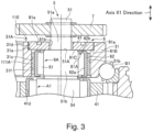
- a bearing retaining mechanism 110 according to an embodiment of the present invention will be hereinafter described with reference to Figs. 2 and 3 .
- the bearing retaining mechanism 110 includes: the first carrier member 31 or the second carrier member 32; the crankshaft 5; the rolling member 6A or the rolling member 6B; a bush 111A or a bush 111B; and the restriction member 9. Description of the bearing retaining mechanism 110 will be omitted for the same configuration as in the bearing retaining mechanism 10.
- the bush 111A is disposed between the first carrier member 31 and the rolling member 6A, and the bush 111B is disposed between the second carrier member 32 and the rolling member 6B.
- the inner periphery of the bush 111A includes a rolling surface for the rolling member 6A
- the inner periphery of the bush 111B includes a rolling surface for the rolling member 6B.
- the restriction member 9 screwed on the carrier 3 is supported by the first carrier member 31 or the second carrier member 32.
- the bush 111A and the bush 111B are examples of "second member" recited in the claims.
- a gap is formed between the restriction member 9 and the bush 111A and/or between the restriction member 9 and the bush 111B.
- the bush 111A is positioned to have a gap formed between the bush 111A and the first restriction member 91.
- the bush 111B is positioned to have a gap formed between the bush 111B and the second restriction member 92.
- a pressure produced upon fastening is received by the first carrier member 31 or the second carrier member 32, and therefore, it is possible to inhibit deformation of the rolling surface of the bush 111A or the rolling surface of the bush 111B. Further, because of the presence of the gap between the bush 111A or the bush 111B and the restriction member 9, the pressure from the restriction member 9 does not act directly on the bush 111A or the bush 111B, and therefore, it is possible to inhibit deformation of the rolling surface of the bush 111A or the rolling surface of the bush 111B. This improves the durability of the bearing retaining mechanism 110.
- the outer cylinder 2 is formed in a substantially cylindrical shape centered at the axis X1.
- Multiple pin grooves are formed in an inner peripheral surface 2a of the outer cylinder 2.
- Each pin groove extends in the axis X1 direction and has a semicircular cross-sectional shape along the plane orthogonal to the axis X1 direction.
- the pin grooves are arranged in a circumferential direction of the outer cylinder 2 at regular intervals.
- the gear device 1 further includes a plurality of inner-tooth pins 8 mounted on the inner peripheral surface 2a of the outer cylinder 2.
- Each of the inner-tooth pins 8 is formed in a circular columnar shape extending in the axis X1 direction.
- the inner-tooth pins 8 are mounted in the pin grooves formed in the inner peripheral surface 2a of the outer cylinder 2.
- a plurality of mounting holes 2b are formed in the outer cylinder 2 so as to extend through the outer cylinder 2 in the axis X1 direction.
- the mounting holes 2b are arranged in the circumferential direction of the outer cylinder 2 at regular intervals.
- the mounting holes 2b are used for mounting a member constituting a joint portion of a robot (not shown) to the outer cylinder 2.
- the outer cylinder 2 serves as a fixed member in the gear device 1.
- the carrier 3 is configured to hold the oscillating gear 4 at both sides in the axis X1 direction and disposed concentrically with the outer cylinder 2.
- the carrier 3 includes the first carrier member 31 and the second carrier member 32 opposed to each other in the axis X1 direction.
- the first carrier member 31 and the second carrier member 32 are fastened to each other via a fastening member T1.
- the first carrier member 31 has a substantially disk-like shape. A part of the first carrier member 31 is positioned inside the outer cylinder 2, while a remaining part of the first carrier member 31 is positioned outside the outer cylinder 2 in the axis X1 direction.
- the first carrier member 31 has a center hole 31a and a crankshaft mounting portion 31b formed therein. The center hole 31a is formed in the center portion of the first carrier member 31 so as to extend through the first carrier member 31 in the axis X1 direction.
- the crankshaft mounting portion 31b receives the crankshaft 5 mounted thereto.
- a plurality of crankshaft mounting portions 31b are arranged on an outer side of the center hole 31a in a circumferential direction of the carrier 3.
- Each of the crankshaft mounting portions 31b is formed of a through-hole extending through the first carrier member 31 in the axis X1 direction or formed of a cavity in the first carrier member 31 concave in the axis X1 direction.
- Each of the crankshaft mounting portions 31b is formed so as to extend through the first carrier member 31 in the axis X1 direction.
- the first carrier member 31 has three crankshaft mounting portions 31b formed therein.
- the second carrier member 32 includes a substantially disk-shaped substrate portion 32a and a shaft portion 32b extending from the substrate portion 32a to the first carrier member 31. A part of the substrate portion 32a is positioned inside the outer cylinder 2, while a remaining part of the substrate portion 32a is positioned outside the outer cylinder 2 in the axis X1 direction.
- the substrate portion 32a has an end surface on the first carrier member 31 side in the axis X1 direction, and the shaft portion 32b extends from the end surface of the substrate portion 32a in the axis X1 direction.
- a plurality of shaft portions 32b are arranged in the circumferential direction of the carrier 3.
- the second carrier member 32 includes three shaft portions 32b.
- the second carrier member 32 includes a center hole 32k, a crankshaft mounting portion 32d, and a mounting hole 32j.
- the center hole 32k is formed in the center portion of the second carrier member 32 so as to extend through the substrate portion 32a of the second carrier member 32 in the axis X1 direction.
- the crankshaft mounting portion 32d receives the crankshaft 5 mounted thereto.
- a plurality of crankshaft mounting portions 32d are arranged on an outer side of the center hole 32k in a circumferential direction of the carrier 3.
- Each of the crankshaft mounting portions 32d is formed of a through-hole extending through the substrate portion 32a in the axis X1 direction or a cavity formed in a part of the substrate portion 32a in the axis X1 direction.
- each of the crankshaft mounting portions 32d is formed so as to extend through the substrate portion 32a of the second carrier member 32 in the axis X1 direction.
- the crankshaft mounting portions 32d are positioned so as to correspond to the positions of the crankshaft mounting portions 31b formed in the first carrier member 31.
- the mounting hole 32j which is formed in the second carrier member 32 in the axis X1 direction, is formed of a cavity in an end surface of the second carrier member 32 on the opposite side to the first carrier member 31.
- the mounting hole 32j is used for mounting a mating member such as a turning barrel forming a joint portion of a robot to the carrier 3.
- the carrier 3 serves as a rotating member in the gear device 1.
- the carrier 3 serves as a fixed member in the gear device 1 and the outer cylinder 2 serves as a rotating member in the gear device 1.
- the gear device 1 further includes main bearings B1, B2.
- the main bearings B1, B2 are disposed between the outer peripheral surface of the carrier 3 and the inner peripheral surface 2a of the outer cylinder 2. More specifically, the main bearing B1 is disposed between the outer peripheral surface of the first carrier member 31 and the inner peripheral surface 2a of the outer cylinder 2, and the main bearing B2 is disposed between the outer peripheral surface of the substrate portion 32a of the second carrier member 32 and the inner peripheral surface 2a of the outer cylinder 2.
- the main bearings B1, B2 allow the relative rotations of the outer cylinder 2 and the carrier 3.
- the crankshaft 5 is rotatably supported on the carrier 3 at the crankshaft mounting portions 31b, 32d.
- the gear device 1 further includes the crank bearing 6 that includes rolling members (crank bearings) 6A, 6B that allow rotation of the crankshaft 5 with respect to the carrier 3.
- the crankshaft 5 is supported on the carrier 3 via the crank bearings 6A, 6B.
- three crankshafts 5 are arranged in the circumferential direction of the carrier 3.
- the number of the crankshafts 5 is not limited and can be changed as appropriate in accordance with an application of the gear device 1.
- the crankshaft 5 includes a shaft main body 51 extending in the axis X1 direction and eccentric portions 54, 55 that are eccentric with respect to the shaft main body 51.
- the shaft main body 51 includes first and second journal portions (large diameter portions) 51b, 51c and a small diameter portion 51a having a slightly smaller diameter than the first and second journal portions 51b, 51c.
- the first journal portion 51b is positioned in the crankshaft mounting portion 31b of the first carrier member 31.
- the rolling member (the first crank bearing) 6A is mounted to the outer peripheral surface of the first journal portion 51b.
- the second journal portion 51c has the same outer diameter as the first journal portion 51b.
- the second journal portion 51c is positioned in the crankshaft mounting portion 32d of the second carrier member 32.
- the rolling member (the second crank bearing) 6B is mounted to the outer peripheral surface of the second journal portion 51c.
- the small diameter portion 51a is adjacent to the first journal portion 51b in the axis X1 direction and extends in the direction opposite to the second journal portion 51c. A part of the small diameter portion 51a is positioned outside the crankshaft mounting portion 31b. It is also possible that the first journal portion 51b extends from inside of the crankshaft mounting portion 31b to outside of the crankshaft mounting portion 31b, thereby to eliminate the small diameter portion 51a.
- the eccentric portions 54, 55 are positioned between the first journal portion 51b and the second journal portion 51c in the axis X1 direction.
- the oscillating gear 4 is mounted to the eccentric portions 54, 55 via eccentric portion bearings A1, A2, respectively.
- the eccentric portion bearings A1, A2 allow relative rotations of the eccentric portions 54, 55 and the oscillating gear 4.
- the oscillating gear 4 is positioned in the outer cylinder 2 and interposed between the first carrier member 31 and the substrate portion 32a of the second carrier member 32 in the rotation axis X1 direction.
- the gear device 1 further includes the eccentric portion bearings A1, A2, and the oscillating gear 4 includes a first oscillating gear 41 mounted to the first eccentric portion 54 via the eccentric portion bearing A1 and a second oscillating gear 42 mounted to the second eccentric portion 55 via the eccentric portion bearing A2.
- the oscillating gears 41, 42 each have an outer diameter slightly smaller than an inner diameter of the outer cylinder 2 and have a plurality of outer teeth formed on the outer peripheral surface thereof.
- the number of the outer teeth formed on the outer peripheral surface of each of the oscillating gears 41, 42 is slightly smaller than the number of the inner-tooth pins 8.
- the first oscillating gear 41 and the second oscillating gear 42 can perform oscillating rotation out of phase with each other so that the outer teeth are engaged with the inner-tooth pins 8 inside the outer cylinder 2.
- the first oscillating gear 41 has formed therein a center hole 41a corresponding to the position of the center hole 31a of the first carrier member 31, an insertion hole 41b into which the shaft portion 32b is inserted, and a crankshaft mounting portion 41c into which the first eccentric portion 54 is inserted.
- the second oscillating gear 42 has formed therein a center hole 42a corresponding to the position of the center hole 32k of the second carrier member 32, an insertion hole 42b into which the shaft portion 32b is inserted, and a crankshaft mounting portion 42c into which the second eccentric portion 55 is inserted.
- the oscillating gear 4 includes two oscillating gears, that is, the first oscillating gear 41 and the second oscillating gear 42, but this is not limitative. It is also possible that the oscillating gear 4 includes only one oscillating gear or three or more oscillating gears.
- the gear device 1 further includes a transmission gear 7 that transmits a drive force to the crankshaft 5 to rotate the crankshaft 5. It is possible that three transmission gears 7 are provided in association with the positions of the three crankshafts 5. In the axis X1 direction, the transmission gear 7 is positioned on an opposite side to the second carrier member 32, with the first carrier member 31 interposed therebetween. The transmission gear 7 is mounted to the small diameter portion 51a of the shaft main body 51 of the crankshaft 5. Movement of the transmission gear 7 in the axis X1 direction is restricted by retaining rings mounted to the small diameter portion 51a of the shaft main body 51, the retaining rings retaining opposite sides of the transmission gear 7 in the axis X1 direction.
- the transmission gear 7 is positioned on an opposite side to the second carrier member 32, with the first carrier member 31 interposed therebetween, but this is not limitative. It is also possible that the transmission gear 7 is positioned, for example, between the first eccentric portion 54 and the second eccentric portion 55. That is, the transmission gear 7 may be positioned in any way, and its position can be changed as appropriate in accordance with aspects of the gear device 1.
- the transmission gear 7 includes a plurality of outer teeth on the outer peripheral surface thereof, and the plurality of outer teeth are engaged with an input shaft or the like of a motor (not shown), such that a drive force (torque) of the motor is transmitted to the crankshaft 5.
- the eccentric portions 54, 55 of the crankshaft 5, which has received the drive force from the transmission gear 7, rotate to cause the oscillating rotation of the oscillating gear 4 in the outer cylinder 2 in accordance with the rotation of the eccentric portions 54, 55.
- the outer cylinder 2 and the carrier 3 rotate relative to each other.
- the gear device 1 further includes the restriction member 9 that restricts movement of the crankshaft 5 in the axis X1 direction.
- the restriction member 9 includes the first restriction member 91 and the second restriction member 92 spaced from each other in the axis X1 direction.
- the first restriction member 91 and the second restriction member 92 are on opposite sides of the crankshaft 5 in the axis X1 direction.
- the bearing retaining mechanism 10 and the bearing retaining mechanism 110 are formed on both sides of the carrier 3 in the axis X1 direction of the gear device 1 shown in Figs. 1 and 2 .
- Fig. 3 shows the bearing retaining mechanism 110 on the upper side in the axis X1 direction of the gear device 1.
- the first restriction member 91 has a disk-like shape and has an insertion hole 91b that extends through a center portion in the axis X1 direction.
- the diameter of the insertion hole 91b is slightly larger than that of the small diameter portion 51a and is smaller than that of the first journal portion 51b. As shown in Fig. 2 , the first restriction member 91 is positioned such that the small diameter portion 51a is positioned in the insertion hole 91b.
- the first restriction member 91 includes an external screw portion 91a for fixing the first restriction member 91 to the carrier 3.
- the external screw portion 91a is formed over the entire circumference of the outer periphery of the first restriction member 91.
- the inner peripheral surface 31c of the first carrier member 31, which forms the crankshaft mounting portion 31b, includes an internal screw portion 31d, a step portion 31e, and a supporting portion 31f.
- the internal screw portion 31d, the step portion 31e, and the supporting portion 31f are arranged in this order from an outer end surface 31A side of the first carrier member 31.
- the internal screw portion 31d extends from an end of the inner peripheral surface 31c on the outer end surface 31A side to an intermediate portion of the inner peripheral surface 31c.
- the internal screw portion 31d is engaged with the external screw portion 91a.
- the restriction member 9 is mounted to the carrier 3.
- the step portion 31e connects between the internal screw portion 31d and the supporting portion 31f.
- the step portion 31e extends from an end of the internal screw portion 31d on the first oscillating gear 41 side in the axis X1 direction to the radial inside of the crankshaft 5.
- the step portion 31e is aligned with an axial end surface 51A of the first journal portion 51b in the direction perpendicular to the axis X1 direction, the axial end surface 51A being opposite to the eccentric portion 54.
- the first restriction member 91 is in contact with the step portion 31e in the axis X1 direction at an outer periphery of the second principal surface 91A thereof.
- the first restriction member 91 is also in contact with an axial end surface 51A of the first journal portion 51b at a center portion of the second principal surface 91A thereof.
- a restriction surface 91C is in contact with the axial end surface 51A of the first journal portion 51b, but this is not limitative. It is also possible that the restriction surface 91C is positioned to leave a gap between the restriction surface 91C and the axial end surface 51A in the axis X1 direction. In such an arrangement, the step portion 31e is closer to the outer end surface 31A than is the axial end surface 51A in the axis X1 direction.
- the supporting portion 31f extends from an inner end of the step portion 31e in the radial direction of the crankshaft 5 toward the first oscillating gear 41 along the axis X1 direction.
- the supporting portion 31f rotatably supports the first journal portion 51b via the rolling member (the first crank bearing) 6A, and the rolling member (the first crank bearing) 6A includes a rolling element 61 extending in the axis X1 direction. Since the rolling element 61 freely rotates between the supporting portion 31f and the first journal portion 51b, the crankshaft 5 can rotate relatively to the carrier 3.
- the second restriction member 92 may have a disk-like shape, as does the first restriction member 91.
- the second restriction member 92 has an insertion hole 92b in a center portion thereof, as does the first restriction member 91.
- the second restriction member 92 includes an external screw portion 92a and a mounting portion 92e, as does the first restriction member 91.
- the inner peripheral surface 32c of the second carrier member 32, which forms the crankshaft mounting portion 32d, includes an internal screw portion 32g, a step portion 32h, and a supporting portion 32f, as does the inner peripheral surface 31c of the first carrier member 31.
- the rolling member (the second crank bearing) 6B includes the rolling element 61, as does the rolling member (the first crank bearing) 6A.
- Each of the second restriction member 92, the inner peripheral surface 32c of the second carrier member 32, and the rolling member (the second crank bearing) 6B is disposed symmetrically to the first restriction member 91, the inner peripheral surface 31c of the first carrier member 31, and the first crank bearing 6A, respectively, in the axis X1 direction. Therefore, detailed description will be omitted for the shapes and arrangements of the second restriction member 92, the inner peripheral surface 32c of the second carrier member 32, and the rolling member (the second crank bearing) 6B.
- the second restriction member 92 is in contact with the step portion 32h in the axis X1 direction, and at this position, the second restriction member 92 faces an axial end surface 51B of the second journal portion 51c on the outer end surface 32A side.
- the second restriction member 92 restricts movement of the crankshaft 5 in the axis X1 direction toward the outer end surface 32A.
- the second restriction member 92 faces a second part 62b of a retainer 62 of the second crank bearing 6B in the axis X1 direction.
- the second restriction member 92 restricts movement of the retainer 62 in the axis X1 direction toward the outer end surface 32A.
- first and second restriction members 91, 92 have recesses 91e, 92e, respectively.
- the recesses 91e, 92e each receive a jig, and the first and second restriction members 91, 92 are rotated with a given fastening torque.
- These recesses may be through-holes as shown in Fig. 2 , such that a lubricant passes through the through-holes to lubricate the bearings 6A, 6B.
Description
- The present invention relates to a gear device having a bearing retaining mechanism.
- There is known a gear device that rotatably supports a crankshaft in a through-hole formed in a carrier.
- A conventional gear device is disclosed in
Patent Literature 1. In the gear device disclosed inPatent Literature 1, an external screw portion of a restriction member is screwed on an internal screw portion of a carrier to fix the restriction member to the carrier, and the restriction member fixed to the carrier restricts the movement of a crankshaft in the axial direction. - Patent Literature 1: Japanese Patent Application Publication No.
JP 2016-130536 A - In conventional gear devices as disclosed in
Patent Literature 1, an external screw portion of a restriction member is screwed on an internal screw portion of a carrier to fix the restriction member to the carrier, and the restriction member restricts the movement of a crankshaft in the axial direction. - However, when the restriction member is fastened to the carrier, the fastening torque causes reduction in circularity or cylindricity of a rolling surface (also referred to as a crank hole) for rolling members. When the rolling members roll on the rolling surface with reduced circularity or cylindricity, the rolling surface may be broken.
-
- The present invention addresses the above drawback, and one object thereof is to reduce the effect of fastening of the restriction member to increase durability of a bearing retaining mechanism.
This object is solved by the subject matter ofclaim 1. - In an embodiment of the present invention, the second member is a bush.
- In a bearing retaining mechanism according to an embodiment of the present invention, it is possible to reduce the effect of fastening of the restriction member, thereby to increase durability of the bearing retaining mechanism.
-
-
Fig. 1 is a sectional view illustrating a gear device containing a bearing retaining mechanism according to an example, not the present invention. -
Fig. 2 is a sectional view illustrating a gear device containing a bearing retaining mechanism according to an embodiment of the present invention. -
Fig. 3 is an enlarged view of a part of the bearing retaining mechanism shown inFig. 2 . - Embodiments of the present invention will now be described with reference to the attached drawings. For convenience of illustration, each drawing shows only main components of a gear device in a simplified manner. The gear device shown in each drawing may include various components not shown.
-
Fig. 1 shows a not claimed example of abearing retaining mechanism 10 and agear device 1 containing thebearing retaining mechanism 10. As shown, thegear device 1 is an eccentric oscillating gear device, for example. Thegear device 1 includes anouter cylinder 2, acarrier 3, an oscillatinggear 4, acrankshaft 5, and a crank bearing 6. Thegear device 1 is configured such that when rotation of thecrankshaft 5 causes oscillating rotation of the oscillatinggear 4, theouter cylinder 2 and thecarrier 3 rotate relatively to each other. Thecarrier 3 includes afirst carrier member 31 and asecond carrier member 32. The carrier 3 (that is, thefirst carrier member 31 and the second carrier member 32) is an example of "first member" recited in the claims. - The
bearing retaining mechanism 10 includes: at least one of thefirst carrier member 31 and thesecond carrier member 32; thecrankshaft 5; at least one of a rollingmember 6A and a rollingmember 6B; at least one of abush 11A and abush 11B; and arestriction member 9. Thecarrier member 31 has an innerperipheral surface 31c, and thecarrier member 32 has an innerperipheral surface 32c. The innerperipheral surface 31c includes aninternal screw portion 31d, and the innerperipheral surface 32c includes aninternal screw portion 32g. Thecrankshaft 5 is rotatably supported on the inner periphery of thecarrier 3. Therestriction member 9 includes at least one of afirst restriction member 91 and asecond restriction member 92. Thefirst restriction member 91 includes anexternal screw portion 91a, and thesecond restriction member 92 includes anexternal screw portion 92a. Theexternal screw portion 91a is screwed on theinternal screw portion 31d, and theexternal screw portion 92a is screwed on theinternal screw portion 32g. Thebush 11A is disposed between thefirst carrier member 31 and therolling member 6A, and thebush 11B is disposed between thesecond carrier member 32 and the rollingmember 6B. The inner periphery of thebush 11A includes a rolling surface for therolling member 6A, and the inner periphery of thebush 11B includes a rolling surface for therolling member 6B. Therestriction member 9 screwed on thecarrier 3 is supported by thefirst carrier member 31 and thebush 11A or by thesecond carrier member 32 and thebush 11B. Thebush 11A and thebush 11B are examples of "second member" recited in the claims. The second member may be a member other than a bush. - In the
bearing retaining mechanism 10 according toFig. 1 , a pressure acting on thebush 11A or thebush 11B upon fastening of therestriction member 9 is distributed to thefirst carrier member 31 or thesecond carrier member 32, and therefore, the pressure acting on thebush 11A or thebush 11B can be reduced. This improves the durability of thebearing retaining mechanism 10. - A
bearing retaining mechanism 110 according to an embodiment of the present invention will be hereinafter described with reference toFigs. 2 and3 . As shown, thebearing retaining mechanism 110 includes: thefirst carrier member 31 or thesecond carrier member 32; thecrankshaft 5; therolling member 6A or therolling member 6B; abush 111A or abush 111B; and therestriction member 9. Description of thebearing retaining mechanism 110 will be omitted for the same configuration as in thebearing retaining mechanism 10. Thebush 111A is disposed between thefirst carrier member 31 and therolling member 6A, and thebush 111B is disposed between thesecond carrier member 32 and the rollingmember 6B. The inner periphery of thebush 111A includes a rolling surface for therolling member 6A, and the inner periphery of thebush 111B includes a rolling surface for therolling member 6B. Therestriction member 9 screwed on thecarrier 3 is supported by thefirst carrier member 31 or thesecond carrier member 32. Thebush 111A and thebush 111B are examples of "second member" recited in the claims. - In the
bearing retaining mechanism 110, a gap is formed between therestriction member 9 and thebush 111A and/or between therestriction member 9 and thebush 111B. In other words, thebush 111A is positioned to have a gap formed between thebush 111A and thefirst restriction member 91. Also, thebush 111B is positioned to have a gap formed between thebush 111B and thesecond restriction member 92. - In the
bearing retaining mechanism 110, a pressure produced upon fastening is received by thefirst carrier member 31 or thesecond carrier member 32, and therefore, it is possible to inhibit deformation of the rolling surface of thebush 111A or the rolling surface of thebush 111B. Further, because of the presence of the gap between thebush 111A or thebush 111B and therestriction member 9, the pressure from therestriction member 9 does not act directly on thebush 111A or thebush 111B, and therefore, it is possible to inhibit deformation of the rolling surface of thebush 111A or the rolling surface of thebush 111B. This improves the durability of thebearing retaining mechanism 110. - Next, a further description will be given of the
gear device 1 shown inFigs. 1 and2 . In thegear device 1, theouter cylinder 2 is formed in a substantially cylindrical shape centered at the axis X1. Multiple pin grooves are formed in an innerperipheral surface 2a of theouter cylinder 2. Each pin groove extends in the axis X1 direction and has a semicircular cross-sectional shape along the plane orthogonal to the axis X1 direction. The pin grooves are arranged in a circumferential direction of theouter cylinder 2 at regular intervals. - The
gear device 1 further includes a plurality of inner-tooth pins 8 mounted on the innerperipheral surface 2a of theouter cylinder 2. Each of the inner-tooth pins 8 is formed in a circular columnar shape extending in the axis X1 direction. The inner-tooth pins 8 are mounted in the pin grooves formed in the innerperipheral surface 2a of theouter cylinder 2. - A plurality of mounting
holes 2b are formed in theouter cylinder 2 so as to extend through theouter cylinder 2 in the axis X1 direction. The mountingholes 2b are arranged in the circumferential direction of theouter cylinder 2 at regular intervals. The mountingholes 2b are used for mounting a member constituting a joint portion of a robot (not shown) to theouter cylinder 2. For example, in mounting a base constituting a joint portion of a robot to theouter cylinder 2, theouter cylinder 2 serves as a fixed member in thegear device 1. - The
carrier 3 is configured to hold theoscillating gear 4 at both sides in the axis X1 direction and disposed concentrically with theouter cylinder 2. Thecarrier 3 includes thefirst carrier member 31 and thesecond carrier member 32 opposed to each other in the axis X1 direction. Thefirst carrier member 31 and thesecond carrier member 32 are fastened to each other via a fastening member T1. - The
first carrier member 31 has a substantially disk-like shape. A part of thefirst carrier member 31 is positioned inside theouter cylinder 2, while a remaining part of thefirst carrier member 31 is positioned outside theouter cylinder 2 in the axis X1 direction. Thefirst carrier member 31 has acenter hole 31a and acrankshaft mounting portion 31b formed therein. Thecenter hole 31a is formed in the center portion of thefirst carrier member 31 so as to extend through thefirst carrier member 31 in the axis X1 direction. - The
crankshaft mounting portion 31b receives thecrankshaft 5 mounted thereto. A plurality ofcrankshaft mounting portions 31b are arranged on an outer side of thecenter hole 31a in a circumferential direction of thecarrier 3. Each of thecrankshaft mounting portions 31b is formed of a through-hole extending through thefirst carrier member 31 in the axis X1 direction or formed of a cavity in thefirst carrier member 31 concave in the axis X1 direction. Each of thecrankshaft mounting portions 31b is formed so as to extend through thefirst carrier member 31 in the axis X1 direction. Thefirst carrier member 31 has threecrankshaft mounting portions 31b formed therein. - The
second carrier member 32 includes a substantially disk-shapedsubstrate portion 32a and ashaft portion 32b extending from thesubstrate portion 32a to thefirst carrier member 31. A part of thesubstrate portion 32a is positioned inside theouter cylinder 2, while a remaining part of thesubstrate portion 32a is positioned outside theouter cylinder 2 in the axis X1 direction. - The
substrate portion 32a has an end surface on thefirst carrier member 31 side in the axis X1 direction, and theshaft portion 32b extends from the end surface of thesubstrate portion 32a in the axis X1 direction. A plurality ofshaft portions 32b are arranged in the circumferential direction of thecarrier 3. In this embodiment, thesecond carrier member 32 includes threeshaft portions 32b. Thesecond carrier member 32 includes acenter hole 32k, acrankshaft mounting portion 32d, and a mountinghole 32j. - The
center hole 32k is formed in the center portion of thesecond carrier member 32 so as to extend through thesubstrate portion 32a of thesecond carrier member 32 in the axis X1 direction. - The
crankshaft mounting portion 32d receives thecrankshaft 5 mounted thereto. A plurality ofcrankshaft mounting portions 32d are arranged on an outer side of thecenter hole 32k in a circumferential direction of thecarrier 3. Each of thecrankshaft mounting portions 32d is formed of a through-hole extending through thesubstrate portion 32a in the axis X1 direction or a cavity formed in a part of thesubstrate portion 32a in the axis X1 direction. In the embodiment, each of thecrankshaft mounting portions 32d is formed so as to extend through thesubstrate portion 32a of thesecond carrier member 32 in the axis X1 direction. Thecrankshaft mounting portions 32d are positioned so as to correspond to the positions of thecrankshaft mounting portions 31b formed in thefirst carrier member 31. - The mounting
hole 32j, which is formed in thesecond carrier member 32 in the axis X1 direction, is formed of a cavity in an end surface of thesecond carrier member 32 on the opposite side to thefirst carrier member 31. The mountinghole 32j is used for mounting a mating member such as a turning barrel forming a joint portion of a robot to thecarrier 3. When the turning barrel forming a joint portion of a robot is mounted to thecarrier 3, thecarrier 3 serves as a rotating member in thegear device 1. For example, when a base forming a joint portion of a robot is mounted to thecarrier 3, the turning barrel forming the joint portion of the robot is mounted to theouter cylinder 2, and therefore, thecarrier 3 serves as a fixed member in thegear device 1 and theouter cylinder 2 serves as a rotating member in thegear device 1. - The
gear device 1 further includes main bearings B1, B2. The main bearings B1, B2 are disposed between the outer peripheral surface of thecarrier 3 and the innerperipheral surface 2a of theouter cylinder 2. More specifically, the main bearing B1 is disposed between the outer peripheral surface of thefirst carrier member 31 and the innerperipheral surface 2a of theouter cylinder 2, and the main bearing B2 is disposed between the outer peripheral surface of thesubstrate portion 32a of thesecond carrier member 32 and the innerperipheral surface 2a of theouter cylinder 2. The main bearings B1, B2 allow the relative rotations of theouter cylinder 2 and thecarrier 3. - The
crankshaft 5 is rotatably supported on thecarrier 3 at thecrankshaft mounting portions gear device 1 further includes the crank bearing 6 that includes rolling members (crank bearings) 6A, 6B that allow rotation of thecrankshaft 5 with respect to thecarrier 3. Thecrankshaft 5 is supported on thecarrier 3 via thecrank bearings crankshafts 5 are arranged in the circumferential direction of thecarrier 3. The number of thecrankshafts 5 is not limited and can be changed as appropriate in accordance with an application of thegear device 1. - The
crankshaft 5 includes a shaftmain body 51 extending in the axis X1 direction andeccentric portions main body 51. - The shaft
main body 51 includes first and second journal portions (large diameter portions) 51b, 51c and asmall diameter portion 51a having a slightly smaller diameter than the first andsecond journal portions 51b, 51c. - The
first journal portion 51b is positioned in thecrankshaft mounting portion 31b of thefirst carrier member 31. The rolling member (the first crank bearing) 6A is mounted to the outer peripheral surface of thefirst journal portion 51b. - The second journal portion 51c has the same outer diameter as the
first journal portion 51b. The second journal portion 51c is positioned in thecrankshaft mounting portion 32d of thesecond carrier member 32. The rolling member (the second crank bearing) 6B is mounted to the outer peripheral surface of the second journal portion 51c. - The
small diameter portion 51a is adjacent to thefirst journal portion 51b in the axis X1 direction and extends in the direction opposite to the second journal portion 51c. A part of thesmall diameter portion 51a is positioned outside thecrankshaft mounting portion 31b. It is also possible that thefirst journal portion 51b extends from inside of thecrankshaft mounting portion 31b to outside of thecrankshaft mounting portion 31b, thereby to eliminate thesmall diameter portion 51a. - The
eccentric portions first journal portion 51b and the second journal portion 51c in the axis X1 direction. Theoscillating gear 4 is mounted to theeccentric portions eccentric portions oscillating gear 4. - The
oscillating gear 4 is positioned in theouter cylinder 2 and interposed between thefirst carrier member 31 and thesubstrate portion 32a of thesecond carrier member 32 in the rotation axis X1 direction. Thegear device 1 further includes the eccentric portion bearings A1, A2, and theoscillating gear 4 includes a firstoscillating gear 41 mounted to the firsteccentric portion 54 via the eccentric portion bearing A1 and a secondoscillating gear 42 mounted to the secondeccentric portion 55 via the eccentric portion bearing A2. The oscillating gears 41, 42 each have an outer diameter slightly smaller than an inner diameter of theouter cylinder 2 and have a plurality of outer teeth formed on the outer peripheral surface thereof. The number of the outer teeth formed on the outer peripheral surface of each of the oscillating gears 41, 42 is slightly smaller than the number of the inner-tooth pins 8. Thus, the first oscillatinggear 41 and the secondoscillating gear 42 can perform oscillating rotation out of phase with each other so that the outer teeth are engaged with the inner-tooth pins 8 inside theouter cylinder 2. - The first
oscillating gear 41 has formed therein acenter hole 41a corresponding to the position of thecenter hole 31a of thefirst carrier member 31, aninsertion hole 41b into which theshaft portion 32b is inserted, and acrankshaft mounting portion 41c into which the firsteccentric portion 54 is inserted. - The second
oscillating gear 42 has formed therein acenter hole 42a corresponding to the position of thecenter hole 32k of thesecond carrier member 32, aninsertion hole 42b into which theshaft portion 32b is inserted, and acrankshaft mounting portion 42c into which the secondeccentric portion 55 is inserted. - In this embodiment, the
oscillating gear 4 includes two oscillating gears, that is, the first oscillatinggear 41 and the secondoscillating gear 42, but this is not limitative. It is also possible that theoscillating gear 4 includes only one oscillating gear or three or more oscillating gears. - The
gear device 1 further includes atransmission gear 7 that transmits a drive force to thecrankshaft 5 to rotate thecrankshaft 5. It is possible that threetransmission gears 7 are provided in association with the positions of the threecrankshafts 5. In the axis X1 direction, thetransmission gear 7 is positioned on an opposite side to thesecond carrier member 32, with thefirst carrier member 31 interposed therebetween. Thetransmission gear 7 is mounted to thesmall diameter portion 51a of the shaftmain body 51 of thecrankshaft 5. Movement of thetransmission gear 7 in the axis X1 direction is restricted by retaining rings mounted to thesmall diameter portion 51a of the shaftmain body 51, the retaining rings retaining opposite sides of thetransmission gear 7 in the axis X1 direction. - In the axis X1 direction, the
transmission gear 7 is positioned on an opposite side to thesecond carrier member 32, with thefirst carrier member 31 interposed therebetween, but this is not limitative. It is also possible that thetransmission gear 7 is positioned, for example, between the firsteccentric portion 54 and the secondeccentric portion 55. That is, thetransmission gear 7 may be positioned in any way, and its position can be changed as appropriate in accordance with aspects of thegear device 1. - The
transmission gear 7 includes a plurality of outer teeth on the outer peripheral surface thereof, and the plurality of outer teeth are engaged with an input shaft or the like of a motor (not shown), such that a drive force (torque) of the motor is transmitted to thecrankshaft 5. Theeccentric portions crankshaft 5, which has received the drive force from thetransmission gear 7, rotate to cause the oscillating rotation of theoscillating gear 4 in theouter cylinder 2 in accordance with the rotation of theeccentric portions outer cylinder 2 and thecarrier 3 rotate relative to each other. - The
gear device 1 further includes therestriction member 9 that restricts movement of thecrankshaft 5 in the axis X1 direction. Therestriction member 9 includes thefirst restriction member 91 and thesecond restriction member 92 spaced from each other in the axis X1 direction. Thefirst restriction member 91 and thesecond restriction member 92 are on opposite sides of thecrankshaft 5 in the axis X1 direction. Thus, thefirst restriction member 91 and thesecond restriction member 92 restrict movement of thecrankshaft 5 in the axis X1 direction. Thebearing retaining mechanism 10 and thebearing retaining mechanism 110 are formed on both sides of thecarrier 3 in the axis X1 direction of thegear device 1 shown inFigs. 1 and2 .Fig. 3 shows thebearing retaining mechanism 110 on the upper side in the axis X1 direction of thegear device 1. - The
first restriction member 91 has a disk-like shape and has aninsertion hole 91b that extends through a center portion in the axis X1 direction. The diameter of theinsertion hole 91b is slightly larger than that of thesmall diameter portion 51a and is smaller than that of thefirst journal portion 51b. As shown inFig. 2 , thefirst restriction member 91 is positioned such that thesmall diameter portion 51a is positioned in theinsertion hole 91b. - The
first restriction member 91 includes anexternal screw portion 91a for fixing thefirst restriction member 91 to thecarrier 3. Theexternal screw portion 91a is formed over the entire circumference of the outer periphery of thefirst restriction member 91. - The inner
peripheral surface 31c of thefirst carrier member 31, which forms thecrankshaft mounting portion 31b, includes aninternal screw portion 31d, astep portion 31e, and a supportingportion 31f. In the embodiment, theinternal screw portion 31d, thestep portion 31e, and the supportingportion 31f are arranged in this order from anouter end surface 31A side of thefirst carrier member 31. - The
internal screw portion 31d extends from an end of the innerperipheral surface 31c on theouter end surface 31A side to an intermediate portion of the innerperipheral surface 31c. Theinternal screw portion 31d is engaged with theexternal screw portion 91a. Thus, therestriction member 9 is mounted to thecarrier 3. - The
step portion 31e connects between theinternal screw portion 31d and the supportingportion 31f. Thestep portion 31e extends from an end of theinternal screw portion 31d on the first oscillatinggear 41 side in the axis X1 direction to the radial inside of thecrankshaft 5. Thestep portion 31e is aligned with anaxial end surface 51A of thefirst journal portion 51b in the direction perpendicular to the axis X1 direction, theaxial end surface 51A being opposite to theeccentric portion 54. - The
first restriction member 91 is in contact with thestep portion 31e in the axis X1 direction at an outer periphery of the secondprincipal surface 91A thereof. Thefirst restriction member 91 is also in contact with anaxial end surface 51A of thefirst journal portion 51b at a center portion of the secondprincipal surface 91A thereof. - In the embodiment, a
restriction surface 91C is in contact with theaxial end surface 51A of thefirst journal portion 51b, but this is not limitative. It is also possible that therestriction surface 91C is positioned to leave a gap between therestriction surface 91C and theaxial end surface 51A in the axis X1 direction. In such an arrangement, thestep portion 31e is closer to theouter end surface 31A than is theaxial end surface 51A in the axis X1 direction. - The supporting
portion 31f extends from an inner end of thestep portion 31e in the radial direction of thecrankshaft 5 toward the first oscillatinggear 41 along the axis X1 direction. The supportingportion 31f rotatably supports thefirst journal portion 51b via the rolling member (the first crank bearing) 6A, and the rolling member (the first crank bearing) 6A includes a rollingelement 61 extending in the axis X1 direction. Since the rollingelement 61 freely rotates between the supportingportion 31f and thefirst journal portion 51b, thecrankshaft 5 can rotate relatively to thecarrier 3. - The
second restriction member 92 may have a disk-like shape, as does thefirst restriction member 91. Thesecond restriction member 92 has aninsertion hole 92b in a center portion thereof, as does thefirst restriction member 91. Thesecond restriction member 92 includes anexternal screw portion 92a and a mountingportion 92e, as does thefirst restriction member 91. The innerperipheral surface 32c of thesecond carrier member 32, which forms thecrankshaft mounting portion 32d, includes aninternal screw portion 32g, astep portion 32h, and a supportingportion 32f, as does the innerperipheral surface 31c of thefirst carrier member 31. The rolling member (the second crank bearing) 6B includes the rollingelement 61, as does the rolling member (the first crank bearing) 6A. Each of thesecond restriction member 92, the innerperipheral surface 32c of thesecond carrier member 32, and the rolling member (the second crank bearing) 6B is disposed symmetrically to thefirst restriction member 91, the innerperipheral surface 31c of thefirst carrier member 31, and the first crank bearing 6A, respectively, in the axis X1 direction. Therefore, detailed description will be omitted for the shapes and arrangements of thesecond restriction member 92, the innerperipheral surface 32c of thesecond carrier member 32, and the rolling member (the second crank bearing) 6B. - The
second restriction member 92 is in contact with thestep portion 32h in the axis X1 direction, and at this position, thesecond restriction member 92 faces anaxial end surface 51B of the second journal portion 51c on theouter end surface 32A side. Thus, thesecond restriction member 92 restricts movement of thecrankshaft 5 in the axis X1 direction toward theouter end surface 32A. Thesecond restriction member 92 faces asecond part 62b of aretainer 62 of the second crank bearing 6B in the axis X1 direction. Thus, thesecond restriction member 92 restricts movement of theretainer 62 in the axis X1 direction toward theouter end surface 32A. Further, the first andsecond restriction members recesses recesses second restriction members Fig. 2 , such that a lubricant passes through the through-holes to lubricate thebearings - The examples of the embodiments of the present invention have been described above. The above-described embodiments are not limited to the configurations described above and can be applied to various types of gear devices, according to the appended claims.
-
LIST OF REFERENCE NUMBERS 1 gear device 2 outer cylinder 3 carrier 4 oscillating gear 5 crankshaft 6 crank bearing 6A, 6B rolling members 7 transmission gear 9 restriction member 10, 110 bearing retaining mechanism 11A, 11B bushes 31 first carrier member 32 second carrier member 31b, 32d crankshaft mounting portions (through-holes) 31c, 32c inner peripheral surfaces 31d, 32g internal screw portions 31e, 32h step portions (positioning portions) 61 rolling element 62, 62a retainer 62b second part 91a, 92a external screw portions 91b insertion hole 91C restriction surface
Claims (2)
- A gear device (1) having a bearing retaining mechanism (110), comprising:a first member (3) having an inner peripheral surface (31c, 32c) including an internal screw portion (31d, 32g);a rolling member (6A, 6B);a retainer (62) holding the rolling member (6A, 6B);a crankshaft (5);a restriction member (9) including at least one of a first restriction member (91) and a second restriction member (92) supported on the first member (3), the restriction member (9) including an external screw portion (91a, 92a) screwed on the internal screw portion (31d, 32g),characterized in thatthe bearing retaining mechanism (110) further composing a second member (111A, 111B) disposed on the inner peripheral surface (31c, 32c);the rolling member (6A, 6B) rolling on a rolling surface formed on the second member (111A, 111B);the crankshaft (5) being rotatably supported on the second member (111A, 111B) via the rolling member (6A, 6B), andthe second member (111A, 111B) is disposed so as to leave a gap between the second member (111A, 111B) and the restriction member (9).
- The gear device (1) of claim 1, wherein the second member (111A, 111B) is a bush.
Applications Claiming Priority (2)
| Application Number | Priority Date | Filing Date | Title |
|---|---|---|---|
| JP2018152983 | 2018-08-15 | ||
| JP2019146842A JP7332387B2 (en) | 2018-08-15 | 2019-08-08 | Bearing retention mechanism |
Publications (2)
| Publication Number | Publication Date |
|---|---|
| EP3611400A1 EP3611400A1 (en) | 2020-02-19 |
| EP3611400B1 true EP3611400B1 (en) | 2024-04-24 |
Family
ID=67658842
Family Applications (1)
| Application Number | Title | Priority Date | Filing Date |
|---|---|---|---|
| EP19191773.1A Active EP3611400B1 (en) | 2018-08-15 | 2019-08-14 | Gear mechanism with a bearing retaining mechanism |
Country Status (3)
| Country | Link |
|---|---|
| US (1) | US10955007B2 (en) |
| EP (1) | EP3611400B1 (en) |
| CN (1) | CN110836255A (en) |
Family Cites Families (6)
| Publication number | Priority date | Publication date | Assignee | Title |
|---|---|---|---|---|
| JPH03103615A (en) * | 1989-09-12 | 1991-04-30 | Railway Technical Res Inst | Electrically insulated bearing |
| CA2182923C (en) * | 1995-08-10 | 2006-10-10 | Walter P. Waskiewicz | Bearing assembly insert |
| DE10023947A1 (en) * | 2000-05-16 | 2001-11-22 | Bosch Gmbh Robert | Anti-friction bearing for piston pump has bearing ring and anti-friction bodies; bearing ring has lateral protrusion with which it can be pressed into bearing seat |
| JP2002266854A (en) * | 2001-03-09 | 2002-09-18 | Minebea Co Ltd | Motor |
| JP6448992B2 (en) | 2014-11-19 | 2019-01-09 | ナブテスコ株式会社 | Gear device |
| JP6554285B2 (en) | 2015-01-13 | 2019-07-31 | ナブテスコ株式会社 | Gear device |
-
2019
- 2019-08-14 US US16/540,895 patent/US10955007B2/en active Active
- 2019-08-14 EP EP19191773.1A patent/EP3611400B1/en active Active
- 2019-08-15 CN CN201910752837.4A patent/CN110836255A/en active Pending
Also Published As
| Publication number | Publication date |
|---|---|
| US20200056650A1 (en) | 2020-02-20 |
| CN110836255A (en) | 2020-02-25 |
| EP3611400A1 (en) | 2020-02-19 |
| US10955007B2 (en) | 2021-03-23 |
Similar Documents
| Publication | Publication Date | Title |
|---|---|---|
| CN101196215B (en) | Support structure for rotation body | |
| JP6047999B2 (en) | Rotating support device | |
| JP7324715B2 (en) | cam device | |
| EP1972807B1 (en) | Roller bearing | |
| TW201632764A (en) | Gear device | |
| EP3611400B1 (en) | Gear mechanism with a bearing retaining mechanism | |
| JP2012132495A (en) | Rolling bearing unit with mounting plate | |
| JP5083873B2 (en) | Eccentric oscillating gear unit | |
| EP3270002B1 (en) | Gear device | |
| JP7332387B2 (en) | Bearing retention mechanism | |
| JP2008232278A (en) | Roller bearing | |
| CN105822750B (en) | Eccentric oscillating gear device | |
| JP2008232311A (en) | Roller bearing | |
| JP2019173917A (en) | Composite bearing | |
| JP2020045927A (en) | Cross roller bearing | |
| JP7301638B2 (en) | Bearing mechanism and reducer | |
| CN111720497B (en) | Cycloidal speed reducer, method for manufacturing cycloidal speed reducer, and motor unit | |
| JP2009162300A (en) | Thrust bearing | |
| CN112145557A (en) | Bearing and speed reducer | |
| KR20220137475A (en) | Pinion bearing | |
| JP2022105927A (en) | Cam follower structure for turret | |
| KR20220096283A (en) | Pinion bearng | |
| JP2024065857A (en) | Splined Ball Screw | |
| JP2021028528A (en) | Bearing mechanism and speed reducer | |
| CN111911595A (en) | Rotating shaft member holding mechanism and speed reducer |
Legal Events
| Date | Code | Title | Description |
|---|---|---|---|
| PUAI | Public reference made under article 153(3) epc to a published international application that has entered the european phase |
Free format text: ORIGINAL CODE: 0009012 |
|
| STAA | Information on the status of an ep patent application or granted ep patent |
Free format text: STATUS: THE APPLICATION HAS BEEN PUBLISHED |
|
| AK | Designated contracting states |
Kind code of ref document: A1 Designated state(s): AL AT BE BG CH CY CZ DE DK EE ES FI FR GB GR HR HU IE IS IT LI LT LU LV MC MK MT NL NO PL PT RO RS SE SI SK SM TR |
|
| AX | Request for extension of the european patent |
Extension state: BA ME |
|
| STAA | Information on the status of an ep patent application or granted ep patent |
Free format text: STATUS: REQUEST FOR EXAMINATION WAS MADE |
|
| 17P | Request for examination filed |
Effective date: 20200818 |
|
| RBV | Designated contracting states (corrected) |
Designated state(s): AL AT BE BG CH CY CZ DE DK EE ES FI FR GB GR HR HU IE IS IT LI LT LU LV MC MK MT NL NO PL PT RO RS SE SI SK SM TR |
|
| STAA | Information on the status of an ep patent application or granted ep patent |
Free format text: STATUS: EXAMINATION IS IN PROGRESS |
|
| 17Q | First examination report despatched |
Effective date: 20211105 |
|
| P01 | Opt-out of the competence of the unified patent court (upc) registered |
Effective date: 20230523 |
|
| GRAP | Despatch of communication of intention to grant a patent |
Free format text: ORIGINAL CODE: EPIDOSNIGR1 |
|
| STAA | Information on the status of an ep patent application or granted ep patent |
Free format text: STATUS: GRANT OF PATENT IS INTENDED |
|
| INTG | Intention to grant announced |
Effective date: 20240116 |
|
| GRAS | Grant fee paid |
Free format text: ORIGINAL CODE: EPIDOSNIGR3 |
|
| GRAA | (expected) grant |
Free format text: ORIGINAL CODE: 0009210 |
|
| STAA | Information on the status of an ep patent application or granted ep patent |
Free format text: STATUS: THE PATENT HAS BEEN GRANTED |
|
| AK | Designated contracting states |
Kind code of ref document: B1 Designated state(s): AL AT BE BG CH CY CZ DE DK EE ES FI FR GB GR HR HU IE IS IT LI LT LU LV MC MK MT NL NO PL PT RO RS SE SI SK SM TR |
|
| REG | Reference to a national code |
Ref country code: GB Ref legal event code: FG4D |
|
| REG | Reference to a national code |
Ref country code: CH Ref legal event code: EP |