EP3611385B1 - Blade retainer for gas turbine engine - Google Patents
Blade retainer for gas turbine engine Download PDFInfo
- Publication number
- EP3611385B1 EP3611385B1 EP19190916.7A EP19190916A EP3611385B1 EP 3611385 B1 EP3611385 B1 EP 3611385B1 EP 19190916 A EP19190916 A EP 19190916A EP 3611385 B1 EP3611385 B1 EP 3611385B1
- Authority
- EP
- European Patent Office
- Prior art keywords
- blade
- web
- brace
- fore
- retainer
- Prior art date
- Legal status (The legal status is an assumption and is not a legal conclusion. Google has not performed a legal analysis and makes no representation as to the accuracy of the status listed.)
- Active
Links
- 238000000034 method Methods 0.000 claims description 7
- 239000007787 solid Substances 0.000 claims description 5
- 239000000463 material Substances 0.000 claims description 4
- 239000007769 metal material Substances 0.000 claims description 3
- 238000004519 manufacturing process Methods 0.000 claims description 2
- 230000013011 mating Effects 0.000 description 17
- 230000000712 assembly Effects 0.000 description 6
- 238000000429 assembly Methods 0.000 description 6
- 239000002131 composite material Substances 0.000 description 6
- 239000000446 fuel Substances 0.000 description 4
- 125000006850 spacer group Chemical group 0.000 description 4
- 238000005452 bending Methods 0.000 description 3
- 238000002485 combustion reaction Methods 0.000 description 3
- 230000014759 maintenance of location Effects 0.000 description 2
- OKTJSMMVPCPJKN-UHFFFAOYSA-N Carbon Chemical compound [C] OKTJSMMVPCPJKN-UHFFFAOYSA-N 0.000 description 1
- 230000000903 blocking effect Effects 0.000 description 1
- 229910052799 carbon Inorganic materials 0.000 description 1
- 239000011153 ceramic matrix composite Substances 0.000 description 1
- 230000001419 dependent effect Effects 0.000 description 1
- 230000000977 initiatory effect Effects 0.000 description 1
- 238000012986 modification Methods 0.000 description 1
- 230000004048 modification Effects 0.000 description 1
- 230000001737 promoting effect Effects 0.000 description 1
Images


Classifications
-
- F—MECHANICAL ENGINEERING; LIGHTING; HEATING; WEAPONS; BLASTING
- F01—MACHINES OR ENGINES IN GENERAL; ENGINE PLANTS IN GENERAL; STEAM ENGINES
- F01D—NON-POSITIVE DISPLACEMENT MACHINES OR ENGINES, e.g. STEAM TURBINES
- F01D5/00—Blades; Blade-carrying members; Heating, heat-insulating, cooling or antivibration means on the blades or the members
- F01D5/12—Blades
- F01D5/28—Selecting particular materials; Particular measures relating thereto; Measures against erosion or corrosion
- F01D5/282—Selecting composite materials, e.g. blades with reinforcing filaments
-
- F—MECHANICAL ENGINEERING; LIGHTING; HEATING; WEAPONS; BLASTING
- F01—MACHINES OR ENGINES IN GENERAL; ENGINE PLANTS IN GENERAL; STEAM ENGINES
- F01D—NON-POSITIVE DISPLACEMENT MACHINES OR ENGINES, e.g. STEAM TURBINES
- F01D5/00—Blades; Blade-carrying members; Heating, heat-insulating, cooling or antivibration means on the blades or the members
- F01D5/30—Fixing blades to rotors; Blade roots ; Blade spacers
- F01D5/32—Locking, e.g. by final locking blades or keys
- F01D5/323—Locking of axial insertion type blades by means of a key or the like parallel to the axis of the rotor
-
- F—MECHANICAL ENGINEERING; LIGHTING; HEATING; WEAPONS; BLASTING
- F01—MACHINES OR ENGINES IN GENERAL; ENGINE PLANTS IN GENERAL; STEAM ENGINES
- F01D—NON-POSITIVE DISPLACEMENT MACHINES OR ENGINES, e.g. STEAM TURBINES
- F01D5/00—Blades; Blade-carrying members; Heating, heat-insulating, cooling or antivibration means on the blades or the members
- F01D5/30—Fixing blades to rotors; Blade roots ; Blade spacers
- F01D5/3007—Fixing blades to rotors; Blade roots ; Blade spacers of axial insertion type
- F01D5/3015—Fixing blades to rotors; Blade roots ; Blade spacers of axial insertion type with side plates
-
- F—MECHANICAL ENGINEERING; LIGHTING; HEATING; WEAPONS; BLASTING
- F04—POSITIVE - DISPLACEMENT MACHINES FOR LIQUIDS; PUMPS FOR LIQUIDS OR ELASTIC FLUIDS
- F04D—NON-POSITIVE-DISPLACEMENT PUMPS
- F04D29/00—Details, component parts, or accessories
- F04D29/26—Rotors specially for elastic fluids
- F04D29/32—Rotors specially for elastic fluids for axial flow pumps
- F04D29/321—Rotors specially for elastic fluids for axial flow pumps for axial flow compressors
- F04D29/322—Blade mountings
- F04D29/323—Blade mountings adjustable
-
- F—MECHANICAL ENGINEERING; LIGHTING; HEATING; WEAPONS; BLASTING
- F01—MACHINES OR ENGINES IN GENERAL; ENGINE PLANTS IN GENERAL; STEAM ENGINES
- F01D—NON-POSITIVE DISPLACEMENT MACHINES OR ENGINES, e.g. STEAM TURBINES
- F01D5/00—Blades; Blade-carrying members; Heating, heat-insulating, cooling or antivibration means on the blades or the members
- F01D5/12—Blades
- F01D5/28—Selecting particular materials; Particular measures relating thereto; Measures against erosion or corrosion
- F01D5/284—Selection of ceramic materials
-
- F—MECHANICAL ENGINEERING; LIGHTING; HEATING; WEAPONS; BLASTING
- F01—MACHINES OR ENGINES IN GENERAL; ENGINE PLANTS IN GENERAL; STEAM ENGINES
- F01D—NON-POSITIVE DISPLACEMENT MACHINES OR ENGINES, e.g. STEAM TURBINES
- F01D5/00—Blades; Blade-carrying members; Heating, heat-insulating, cooling or antivibration means on the blades or the members
- F01D5/30—Fixing blades to rotors; Blade roots ; Blade spacers
- F01D5/3084—Fixing blades to rotors; Blade roots ; Blade spacers the blades being made of ceramics
-
- F—MECHANICAL ENGINEERING; LIGHTING; HEATING; WEAPONS; BLASTING
- F05—INDEXING SCHEMES RELATING TO ENGINES OR PUMPS IN VARIOUS SUBCLASSES OF CLASSES F01-F04
- F05D—INDEXING SCHEME FOR ASPECTS RELATING TO NON-POSITIVE-DISPLACEMENT MACHINES OR ENGINES, GAS-TURBINES OR JET-PROPULSION PLANTS
- F05D2220/00—Application
- F05D2220/30—Application in turbines
- F05D2220/36—Application in turbines specially adapted for the fan of turbofan engines
-
- F—MECHANICAL ENGINEERING; LIGHTING; HEATING; WEAPONS; BLASTING
- F05—INDEXING SCHEMES RELATING TO ENGINES OR PUMPS IN VARIOUS SUBCLASSES OF CLASSES F01-F04
- F05D—INDEXING SCHEME FOR ASPECTS RELATING TO NON-POSITIVE-DISPLACEMENT MACHINES OR ENGINES, GAS-TURBINES OR JET-PROPULSION PLANTS
- F05D2240/00—Components
- F05D2240/20—Rotors
- F05D2240/24—Rotors for turbines
-
- F—MECHANICAL ENGINEERING; LIGHTING; HEATING; WEAPONS; BLASTING
- F05—INDEXING SCHEMES RELATING TO ENGINES OR PUMPS IN VARIOUS SUBCLASSES OF CLASSES F01-F04
- F05D—INDEXING SCHEME FOR ASPECTS RELATING TO NON-POSITIVE-DISPLACEMENT MACHINES OR ENGINES, GAS-TURBINES OR JET-PROPULSION PLANTS
- F05D2240/00—Components
- F05D2240/80—Platforms for stationary or moving blades
-
- F—MECHANICAL ENGINEERING; LIGHTING; HEATING; WEAPONS; BLASTING
- F05—INDEXING SCHEMES RELATING TO ENGINES OR PUMPS IN VARIOUS SUBCLASSES OF CLASSES F01-F04
- F05D—INDEXING SCHEME FOR ASPECTS RELATING TO NON-POSITIVE-DISPLACEMENT MACHINES OR ENGINES, GAS-TURBINES OR JET-PROPULSION PLANTS
- F05D2240/00—Components
- F05D2240/90—Mounting on supporting structures or systems
-
- F—MECHANICAL ENGINEERING; LIGHTING; HEATING; WEAPONS; BLASTING
- F05—INDEXING SCHEMES RELATING TO ENGINES OR PUMPS IN VARIOUS SUBCLASSES OF CLASSES F01-F04
- F05D—INDEXING SCHEME FOR ASPECTS RELATING TO NON-POSITIVE-DISPLACEMENT MACHINES OR ENGINES, GAS-TURBINES OR JET-PROPULSION PLANTS
- F05D2260/00—Function
- F05D2260/30—Retaining components in desired mutual position
- F05D2260/31—Retaining bolts or nuts
-
- F—MECHANICAL ENGINEERING; LIGHTING; HEATING; WEAPONS; BLASTING
- F05—INDEXING SCHEMES RELATING TO ENGINES OR PUMPS IN VARIOUS SUBCLASSES OF CLASSES F01-F04
- F05D—INDEXING SCHEME FOR ASPECTS RELATING TO NON-POSITIVE-DISPLACEMENT MACHINES OR ENGINES, GAS-TURBINES OR JET-PROPULSION PLANTS
- F05D2260/00—Function
- F05D2260/30—Retaining components in desired mutual position
- F05D2260/36—Retaining components in desired mutual position by a form fit connection, e.g. by interlocking
-
- F—MECHANICAL ENGINEERING; LIGHTING; HEATING; WEAPONS; BLASTING
- F05—INDEXING SCHEMES RELATING TO ENGINES OR PUMPS IN VARIOUS SUBCLASSES OF CLASSES F01-F04
- F05D—INDEXING SCHEME FOR ASPECTS RELATING TO NON-POSITIVE-DISPLACEMENT MACHINES OR ENGINES, GAS-TURBINES OR JET-PROPULSION PLANTS
- F05D2260/00—Function
- F05D2260/70—Adjusting of angle of incidence or attack of rotating blades
-
- F—MECHANICAL ENGINEERING; LIGHTING; HEATING; WEAPONS; BLASTING
- F05—INDEXING SCHEMES RELATING TO ENGINES OR PUMPS IN VARIOUS SUBCLASSES OF CLASSES F01-F04
- F05D—INDEXING SCHEME FOR ASPECTS RELATING TO NON-POSITIVE-DISPLACEMENT MACHINES OR ENGINES, GAS-TURBINES OR JET-PROPULSION PLANTS
- F05D2260/00—Function
- F05D2260/94—Functionality given by mechanical stress related aspects such as low cycle fatigue [LCF] of high cycle fatigue [HCF]
- F05D2260/941—Functionality given by mechanical stress related aspects such as low cycle fatigue [LCF] of high cycle fatigue [HCF] particularly aimed at mechanical or thermal stress reduction
-
- F—MECHANICAL ENGINEERING; LIGHTING; HEATING; WEAPONS; BLASTING
- F05—INDEXING SCHEMES RELATING TO ENGINES OR PUMPS IN VARIOUS SUBCLASSES OF CLASSES F01-F04
- F05D—INDEXING SCHEME FOR ASPECTS RELATING TO NON-POSITIVE-DISPLACEMENT MACHINES OR ENGINES, GAS-TURBINES OR JET-PROPULSION PLANTS
- F05D2300/00—Materials; Properties thereof
- F05D2300/60—Properties or characteristics given to material by treatment or manufacturing
- F05D2300/603—Composites; e.g. fibre-reinforced
- F05D2300/6033—Ceramic matrix composites [CMC]
Landscapes
- Engineering & Computer Science (AREA)
- Mechanical Engineering (AREA)
- General Engineering & Computer Science (AREA)
- Chemical & Material Sciences (AREA)
- Materials Engineering (AREA)
- Composite Materials (AREA)
- Structures Of Non-Positive Displacement Pumps (AREA)
- Turbine Rotor Nozzle Sealing (AREA)
Description
- The present disclosure relates generally to fan blade assemblies for use in gas turbine engines, and more specifically to fan blade restraints that limit movement of fan blades.
- Gas turbine engines are used to power aircraft, watercraft, power generators, and the like. Gas turbine engines typically include a fan, a compressor, a combustor, and a turbine. The compressor compresses air drawn into the engine by the fan and delivers high pressure air to the combustor. In the combustor, fuel is mixed with the high pressure air and is ignited. Products of the combustion reaction in the combustor are directed into the turbine where work is extracted to drive the compressor and, sometimes, an output shaft. Left over products of the combustion are exhausted out of the turbine and may provide thrust in some applications.
-
US 3 383 095 discloses a lock for turbomachinery blades having a retainer with outwardly and inwardly extending legs at its opposite ends and a keeper for maintaining the retainer in a locking position in which it locks the blade.DE 100 31 116 A1GB 2 021 206 A US 3 632 228 discloses a blade locking device having a spacer, a bolt to be inserted into the spacer, the bold having a head and a threaded end, a plate to be attached to the threaded end and a nut to fix the plate. - The fan assembly generally includes a hub having a plurality of fan blades that rotate about a center axis of the gas turbine engine. Some fixed pitch dovetail fan blades require adjacent blade exerting forces on the dovetail surfaces to prevent any bending of the disc lug posts. In a variable pitch fan blade, each blade is independent of each other therefore the prying force to open the dovetail has no counteracting force. This exerts force on the dovetail that can create bending forces and generate edge loading on the corners of the dovetail. Given solidity constraints at the hub, there is less bearing area to support the dovetail blade load. Variable pitch fan blade design can also be challenging because of other solidity constraints near the hub. Accordingly, additional design options related to variable pitch fan blade systems are needed.
- The above-mentioned problems are solved by the blade assembly according to claim 1 and a method according to
claim 10. - According to the present invention, the blade assembly includes a blade configured to rotate about a center axis during operation of the gas turbine engine, a blade holder configured to support the blade as the blade rotates about the center axis, and a blade retainer configured to block axial movement of the root of the blade out of the blade receiver slot. The blade includes a root and an airfoil that extends radially away from the root. The blade holder includes a base, a first post, and a second post that cooperate to define a blade receiver slot that extends axially through a fore face and an aft face of the blade holder. The receiver slot also receives the root of the blade such that the first post and the second post block radial movement of the root of the blade out of the blade receiver slot.
- According to the invention, the blade retainer includes an outer stop and a retainer insert. The retainer insert includes a web, a fore brace, and an inner stop. The web extends axially between a fore end and an aft end. The fore brace is coupled to the fore end of the web. The inner stop extends radially inward away from the web adjacent the aft end of the web. The outer stop is aligned axially with the inner stop and is coupled to the web to cause the outer stop and the inner stop to cooperate thereby providing an aft brace that is spaced apart axially from the fore brace. The fore brace is configured to engage the root of the blade and the fore face of the blade holder. The aft brace is configured to engage the root of the blade and the aft face of the blade holder. The web blocks relative movement between the fore brace and the aft brace so that the blade retainer blocks axial movement of the root of the blade out of the blade receiver slot.
- The outer stop includes a radially extending abutment wall and a flange that extends axially away from the abutment wall. The web is formed to include a channel that extends radially into the web and a portion of the abutment wall is received in the channel to locate the outer stop axially relative to the retainer insert. I he channel is aligned axially with the inner stop.
- Further preferred embodiments are defined by the dependent claims.
- According to another aspect of the present invention, a method of making a blade retainer for the blade assembly according to the first aspect of the present invention adapted to block axial movement of a blade in a gas turbine engine is disclosed. The method includes providing a first segment of a bar stock comprising metallic material. The method further includes removing material from the first segment of the bar stock to form an integral retainer insert that includes: (i) a web that extends axially relative to an axis of the bar stock, (ii) a first brace that extends radially outward and radially inward away from the web, and (iii) a first stop that extends radially away from the web, the first brace being spaced apart axially from the first stop.
- According to the present invention, the method includes providing a second segment of the bar stock. The method further includes removing material from the second segment of the bar stock to form a second stop that includes an abutment wall and a flange that extends axially away from the abutment wall.
- In illustrative embodiments, the bar stock used in the disclosed method is cylindrical. However, other bar stock shapes can also be used.
- These and other features of the present invention will become more apparent from the following description of the illustrative embodiments.
-
-
Fig. 1 is a cutaway view of a gas turbine engine that includes a variable pitch fan, a compressor, a combustor, and a turbine, the variable pitch fan including a plurality of fan blade assemblies mounted for rotation about an axis of the gas turbine engine to produce thrust and configured to have their pitch varied during operation of the gas turbine engine; -
Fig. 2 is a perspective view of one of the fan blade assemblies ofFig. 1 showing that the fan blade assembly includes a fan blade holder, a fan blade received in a slot formed in the fan blade holder, and a blade retainer; -
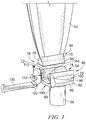
Fig. 3 is an exploded view of one of the fan blade assemblies shown inFig. 1 and a blade retainer configured to couple to the fan blade assembly to reduce forward and aft movement of the fan blade; -
Fig. 4 is a perspective view of a blade retainer including an outer stop coupled to a retainer insert; -
Fig. 5 is an expanded view of the outer stop shown inFig. 4 coupled to the retainer insert shown inFig. 4 ; -
Fig. 6 is an exploded view of the blade retainer ofFig. 4 configured to couple between the fan blade shown inFig.3 and the blade holder shown inFig. 3 ; -
Fig. 7 is a side elevation view of the blade retainer ofFig. 4 coupled between the fan blade shown inFig.3 and the blade holder shown inFig. 3 ; -
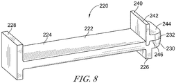
Fig. 8 is a perspective view of another embodiment of a blade retainer having an outer stop bonded to a retainer insert; and -
Fig. 9 is a perspective view of a fan blade assembly coupled to a disc. - For the purposes of promoting an understanding of the principles of the invention, reference will now be made to a number of illustrative embodiments illustrated in the drawings and specific language will be used to describe the same.
- A
gas turbine engine 10 in accordance with the present disclosure is shown inFig. 1 . Thegas turbine engine 10 includes avariable pitch fan 12, acompressor 14, acombustor 16, and aturbine 18. Thefan 12 is driven by theturbine 18 and provides thrust for propelling an aircraft. Thecompressor 14 compresses and delivers air to thecombustor 16. Thecombustor 16 mixes fuel with the compressed air received from thecompressor 14 and ignites the fuel. The hot, high pressure products of the combustion reaction in thecombustor 16 are directed into theturbine 18 to cause theturbine 18 to rotate about acenter axis 11 of thegas turbine engine 10 and drive thecompressor 14 and thefan 12. - The
illustrative fan 12 is avariable pitch fan 12 that includes a plurality offan blade assemblies 40 extending from ahub 38 and that each include afan blade holder 42 and afan blade 28 mounted in thefan blade holder 42. Thefan blade assembly 40 is configured to rotate about thecenter axis 11 as suggested inFig. 1 such that thefan blades 28 produce thrust. Thefan blade assemblies 40 are arranged circumferentially about thecenter axis 11 and are configured to rotate about corresponding radially extending fan blade pivot axes 30 to change a pitch (sometimes called an incident angle) of thefan blades 28. - As one example, the pitch of the
fan blades 28 may be varied to optimize fuel burn throughout a flight mission. The pitch of thefan blades 28 may be reversed to provide thrust reverse and reduce or eliminate the use of heavy thrust reverse units coupled to the engine nacelle. Thefan blades 28 may be feathered in the event of an engine failure to reduce drag or windmill loads. - Referring to
Fig. 2 , afan blade assembly 40 includes thefan blade holder 42 and thefan blade 28. Thefan blade holder 42 includes a metallic material and is configured to retain thefan blade 28 as thefan blade 28 rotates about thecenter axis 11. Thefan blade 28 may be a composite material, e.g. organic composite, ceramic matrix composite, or carbon composite. Thefan blade holder 42 is adapted to rotate selectively about the fanblade pivot axis 30 to vary a pitch of thefan blade 28. Thefan blade holder 42 includes ashank 50 and ablade restraint 52 that extends between anaft face 98 and afore face 106. Theshank 50 is generally cylindrical in shape and extends along the fanblade pivot axis 30. Theshank 50 is configured to position in an opening of thehub 38. Theshank 50 rotates about the fanblade pivot axis 30 within the opening of thehub 38. Theblade restraint 52 extends radially outward from theshank 50 and includes a dovetail shapedblade receiver slot 54. - The
fan blade 28 includes a composite material and is configured to rotate about thecenter axis 11 during operation of thegas turbine engine 10. Thefan blade 28 includes a dovetail shapedroot 60 and anairfoil 62 extending radially outward from theroot 60. Theroot 60 is positioned within theblade receiver slot 54 so that thefan blade 28 is secured to thefan blade holder 42. Theairfoil 62 includes aleading edge 80 and anopposite trialing edge 82. Asuction side 84 of theairfoil 62 extends between theleading edge 80 and the trialingedge 82. Apressure side 86 of theairfoil 62 extends between theleading edge 80 and the trialingedge 82 opposite thesuction side 84. Ablade retainer 130 is positioned between thefan blade 28 and thefan blade holder 42. - Referring to
Fig. 3 , theroot 60 has a pair of angled mating surfaces 70 extending from abottom surface 72 to theairfoil 62. Theroot 60 is positioned within theblade receiver slot 54 so that the angled mating surfaces 70 engage apost 74 and apost 76 of thefan blade holder 42. The mating surfaces 70 extend between afront face 78 and arear face 88. Thefan blade holder 42 includes theshank 50 and ablade restraint 52 that extends radially outward from theshank 50. Theblade restraint 52 includes abase 92. Theposts posts blade receiver slot 54. - The
posts aft face 98 and thefore face 106 of theblade restraint 52. Eachpost fixed end 94 coupled to thebase 92 and afree end 96. Thefree end 96 is positioned radially outward from the fixedend 94. Eachpost outer wall 100 and aninner wall 102 coupled by ajoin wall 104, theouter wall 100 being thicker than theinner wall 102. Theouter wall 100, thejoin wall 104, and theinner wall 102 are solid and integrally formed. Theouter wall 100 extends radially outward from thebase 92. Thejoin wall 104 extends at an angle relative to theouter wall 100 toward theopposite post join wall 104 extends at an orthogonal angle relative to theouter wall 100. Theinner wall 102 extends radially inward from thejoin wall 104 into theblade receiver slot 54. Theinner wall 102 is cantilevered from thejoin wall 104. - A
relief slot 110 is defined between theouter wall 100 and theinner wall 102. The relief slot extends through thefore face 106 and theaft face 98. That is, theinner wall 102 is spaced apart from theouter wall 100 to locate therelief slot 110 therebetween. Therelief slot 110 extends radially relative to thecenter axis 11 through thepost blade receiver slot 54. - Each
relief slot 110 is L shaped and includes an opening 116 that faces theopposite post relief slots 110 enable theposts root 60 in response to thefan blade 28 being urged radially outward relative to thecenter axis 30 by centrifugal forces acting on thefan blade 28 during operation of thegas turbine engine 10. - The
inner wall 102 includes aplanar engagement surface 112 and aninner surface 114. Theengagement surface 112 is continuous such that it is formed without holes. Theblade receiver slot 54 is defined between the engagement surfaces 112 of theposts relief slot 110 is defined between theinner surface 114 and theouter wall 100. Theengagement surface 112 is configured to engage theroot 60 of thefan blade 28. Particularly, anangled mating surface 70 of theroot 60 is configured to engage theengagement surface 112 of eachpost fan blade 28 is coupled to thefan blade holder 42 to block radial movement of thefan blade 28 out of the blade-receiver slot 54 relative to thecenter axis 11. - The
fan blade 28 is configured to position in thefan blade holder 42 so that as air gap is formed between theroot 60 of thefan blade 28 and thebase 92 of thefan blade holder 42. When thegas turbine engine 10 is operated, centrifugal forces act on thefan blade 28 in the direction of arrow 120. These forces move thefan blade 28 radially outward causing stresses to be created between the mating surfaces 70 of theroot 60 and the engagement surfaces 112 of theposts posts posts fan blade 28 becoming dislodged from theblade restraint 52. - To uniformly distribute the forces acting between the
blade restraint 52 and theroot 60, theinner walls 102 of theposts inner walls 102 deform into therelief slots 110. Theinner walls 102 are deformed so that the mating surfaces 70 of theroot 60 maintain a substantially uniform engagement with the engagement surfaces 112. The uniform engagement results in the stresses being uniformly distributed across the engagement surfaces 112 to reduce the occurrence of pressure points on theposts blade restraint 52. It should be noted that theinner walls 102 deform to a point that uniformly distributes the stress while retaining thefan blade 28 in thefan blade holder 42. - The
blade retainer 130 is configured to position in the air gap between thefan blade 28 and thefan blade holder 42. Referring toFig. 4 , theblade retainer 130 includes anouter stop 190 that is configured to couple to aretainer insert 128. Theretainer insert 128 includes aweb 132 extending between anaft brace 134 and afore brace 136. Theweb 132 has awidth 140 that is sized to be received in theblade receiver slot 54. Alength 142 of theweb 132 is substantially the same as a length of theblade receiver slot 54 between theaft face 98 and thefore face 106. - The
fore brace 136 is generally circular in shape and includes aninner stop 150 extending radially outward and aninner stop 152 extending radially inward. Thefore brace 136 is solid, continuous, and circular when viewed axially relative to thecenter axis 11. Thefore brace 136, theweb 132, and theinner stops fore brace 136 has acircumference 154 that is substantially the same aswidth 140 of theweb 132. Thefore brace 136 includes a pair of engagement surfaces 160, 162 that engage thefore face 106 of theblade restraint 52 and thefront face 78 of theroot 60. Theengagement surface 160 is positioned on theinner stop 150, and theengagement surface 162 is positioned on theinner stop 152. - The
aft brace 134 include a substantiallysemi-circular abutment wall 170. Theabutment wall 170 has a circumferential width 172 that is substantially the same as thecircumferential width 140 of theweb 132. Theabutment wall 170 extends radially inward from theweb 132. Anengagement surface 174 of theabutment wall 170 is configured to engage the aft face 98 of theblade restraint 52 and therear face 88 of theroot 60. Aflange 180 extends in an aft direction from theabutment wall 170. Theflange 180 is substantially planar with theweb 132. Theflange 180 includes amating surface 182 on the radiallyoutward face 184. - The
outer stop 190 is removably coupled to theflange 180 to secure theblade retainer 130 to thefan blade assembly 40. Theouter stop 190 is aligned axially with theinner stop 150. Theouter stop 190 includes asemi-circular abutment wall 192 that extends radially outward from theweb 132. Theweb 132 is formed to include achannel 198 that extends radially into theweb 132 and a portion of theabutment wall 192 is received in thechannel 198 to locate theouter stop 190 axially relative to theretainer insert 128. Thechannel 198 is aligned axially with theinner stop 150. Theabutment wall 192 has acircumferential width 194 that is substantially the same as thecircumferential width 140 of theweb 132. Theabutment wall 192 includes anengagement surface 196 that is configured to engage the aft face 98 of theblade restraint 52 and therear face 88 of theroot 60. - A
flange 200 extends axially away from theabutment wall 192 in an aft direction. Theflange 200 includes amating surface 202 that engages themating surface 182 of theflange 180. - Referring to
Fig. 5 , themating surface 202 of theflange 200 is secured against themating surface 182 of theflange 180. Afastener 210 is extended through theflanges outer stop 190 to theaft brace 134. Referring toFig. 6 , theretainer insert 128 is positioned between theroot 60 and theblade restraint 52. That is, with theouter stop 190 removed from theretainer insert 128, theweb 132 of theretainer insert 128 is configured to be slid into the air gap between theroot 60 and theblade restraint 52 so that theaft brace 134 is positioned outside of the air gap aft of thefan blade assembly 40. - As shown, in
Fig. 7 , when theouter stop 190 is fastened to theaft brace 134, theblade retainer 130 is secured between theroot 60 and theblade restraint 52 so that the engagement surfaces 160, 162 are secured against thefore face 106 of theblade restraint 52 and thefront face 78 of theroot 60. The engagement surfaces 174, 196 are secured against theaft face 98 of theblade restraint 52 and therear face 88 of theroot 60. In this configuration, theblade retainer 130 is configured to prevent forward and aft movement of thefan blade 28 relative to theblade restraint 52. - Referring to
Fig. 8 ablade retainer 220 includes aretainer insert 222 having aweb 224 extending between a squaredaft brace 226 and arectangular fore brace 228. Thefore brace 228 is solid, continuous, and rectangular when viewed axially relative to the center axis. Aflange 230 having amating surface 232 extends from theaft brace 226. Anouter stop 240 is configured to join to theflange 230. Theouter stop 240 includes a rectangularaft flange 242 and amating flange 244 extending from theaft flange 242. Themating flange 244 includes amating surface 246 that is configured to be bonded to themating surface 232 of theflange 230. - Referring to
Fig. 9 , thefan blade assembly 40 may be coupled to adisc 250 using either theblade retainer 130 or theblade retainer 220. - In the embodiments described herein the overall length of the blade restraint is approximately equal to the dovetail length. This reduces the total bearing area of the dovetail, thus limiting blade robustness.
- In a variable pitch fan blade designs, each blade is independent of each other therefore the prying force to open the dovetail has no counteracting force. This can exert force on the dovetail that not only creates high bending forces, but generates edge loading on the corners of the dovetail. Given solidity constraints at the hub, there may be less bearing area to support the dovetail blade load. Point loading and edge of bedding have been a consistent problem in composite blade design. This edge loading can cause initiation of failure on composite root designs. This failure can propagate quickly under blade vibrations. Designs in accordance with the present disclosure can be used in solutions to these challenges.
- Variable pitch fan blade design can also be challenged because of solidity constraints near the hub. Some fixed pitch fans usually have solidity greater than 1 while variable pitch fans have constraints less than 1. The solidity is constrained by the fact that the blades need to rotate past each other without clashing. A compact axial retention system provided by the disclosed designs and can prevent the blade from sliding out under aero or bird strike loads. The more the axial retention sticks out, the further the blade solidity has to be reduced. The solidity also drives hub to tip diameter ratio. Some fixed pitch designs use a shear key integrated into the dovetail. This can add length to the dovetail slot because it is done on both the forward and aft end, thus increasing overall length.
- While the invention has been illustrated and described in detail in the foregoing drawings and description, the same is to be considered as exemplary and not restrictive in character, it being understood that only illustrative embodiments thereof have been shown and described and that all changes and modifications that come within the scope of the invention as defined by the appended claims are desired to be protected.
Claims (10)
- A blade assembly for use with a gas turbine engine (10), the blade assembly comprising
a blade (28) configured to rotate about a center axis (11) during operation of the gas turbine engine (10), the blade (28) including a root (60) and an airfoil (62) that extends radially away from the root (60),
a blade holder (42) configured to support the blade (28) as the blade (28) rotates about the center axis (11), the blade holder (42) including a base (92), a first post (74), and a second post (76) that cooperate to define a blade receiver slot (54) that extends axially through a fore face (106) and an aft face (98) of the blade holder (42) and that receives the root (60) of the blade (28) such that the first post (74) and the second post (76) block radial movement of the root (60) of the blade (28) out of the blade receiver slot (54), and
a blade retainer (130, 220) configured to block axial movement of the root (60) of the blade (28) out of the blade receiver slot (54), the blade retainer (130, 220) including an outer stop (190, 240) and a retainer insert (128, 222) that includes a web (132, 224) that extends axially between a fore end and an aft end thereof, a fore brace (136, 228) coupled to the fore end of the web (132, 224), and an inner stop (170) that extends radially inward away from the web (132, 224) adjacent the aft end of the web (132, 224),
wherein the outer stop (190, 240) is aligned axially with the inner stop (170) and coupled to the web (132, 224) to cause the outer stop (190, 240) and the inner stop (170) cooperate to provide an aft brace that is spaced apart axially from the fore brace (136, 228), the fore brace (136, 228) is configured to engage the root (60) of the blade (28) and the fore face of the blade holder (42), the aft brace is configured to engage the root (60) of the blade (28) and the aft face of the blade holder (42), and the web (132, 224) blocks relative movement between the fore brace (136, 228) and the aft brace so that the blade retainer (130, 220) blocks axial movement of the root (60) of the blade (28) out of the blade receiver slot, wherein the outer stop (190, 240) includes a radially extending abutment wall (192, 242) and a flange (200, 244) that extends axially away from the abutment wall (192, 242), the blade assembly being characterised in that the web (132, 224) is formed to include a channel (198) that extends radially into the web (132, 224) and a portion of the abutment wall (192, 242) is received in the channel (198) to locate the outer stop (190, 240) axially relative to the retainer insert (128, 222). - The blade assembly of claim 1, wherein the channel (198) is aligned axially with the inner stop (170).
- The blade assembly of claim 1, wherein the blade retainer (130, 220) further includes a fastener that extends through the flange (200, 244) of the outer stop (190, 240) and the aft end of the web (132, 224) to couple the outer stop (190, 240) to the retainer insert (128, 222),
- The blade assembly of claim 1, wherein the blade retainer (130, 220) further includes a bond layer located between the flange (200, 244) of the outer stop (190, 240) and the aft end of the web (132, 224) to couple the outer stop (190, 240) to the retainer insert (128, 222).
- The blade assembly of claim 1, wherein the outer stop (190, 240) is removably coupled to the retainer insert (128, 222).
- The blade assembly of claim 1, wherein the fore brace (136, 228) is solid, continuous, and circular when viewed axially relative to the center axis (11).
- The blade assembly of claim 6, wherein the fore brace (136, 228), the web (132, 224), and the inner stop (, 170) are integrally formed as a single component.
- The blade assembly of claim 1, wherein the fore brace (136, 228) is solid, continuous, and rectangular when viewed axially relative to the center axis (11).
- The blade assembly of claim 1,
wherein the web (132, 224) has a circumferential width, the fore brace has a circumferential width, and the circumferential width of the fore brace is equal to the circumferential width of the web (132, 224). - A method of making a blade retainer for the blade assembly according to any of the claims 1 to 9 adapted to block movement of a blade (28) in a gas turbine engine (10), the method comprising
providing a first segment of a bar stock comprising metallic material, in particular the bar stock being cylindrical,
removing material from the first segment of the bar stock to form an integral retainer insert (128, 222) that includes a web (132, 224) that extends axially relative to an axis of the bar stock, a first brace that extends radially outward and radially inward away from the web (132, 224), and a first stop that extends radially away from the web (132, 224), the first brace being spaced apart axially from the first stop,
providing a second segment of the bar stock, and
removing material from the second segment of the bar stock to form a second stop that includes an abutment wall (170, 192) and a flange (180, 200) that extends axially away from the abutment wall (170, 192).
Applications Claiming Priority (1)
| Application Number | Priority Date | Filing Date | Title |
|---|---|---|---|
| US16/103,419 US11339674B2 (en) | 2018-08-14 | 2018-08-14 | Blade retainer for gas turbine engine |
Publications (3)
| Publication Number | Publication Date |
|---|---|
| EP3611385A2 EP3611385A2 (en) | 2020-02-19 |
| EP3611385A3 EP3611385A3 (en) | 2020-04-22 |
| EP3611385B1 true EP3611385B1 (en) | 2021-04-07 |
Family
ID=67587582
Family Applications (1)
| Application Number | Title | Priority Date | Filing Date |
|---|---|---|---|
| EP19190916.7A Active EP3611385B1 (en) | 2018-08-14 | 2019-08-09 | Blade retainer for gas turbine engine |
Country Status (3)
| Country | Link |
|---|---|
| US (1) | US11339674B2 (en) |
| EP (1) | EP3611385B1 (en) |
| CA (1) | CA3051750A1 (en) |
Families Citing this family (4)
| Publication number | Priority date | Publication date | Assignee | Title |
|---|---|---|---|---|
| US10876429B2 (en) | 2019-03-21 | 2020-12-29 | Pratt & Whitney Canada Corp. | Shroud segment assembly intersegment end gaps control |
| FR3115818B1 (en) * | 2020-10-30 | 2023-10-20 | Safran Aircraft Engines | Turbomachine fan comprising variable pitch blades |
| FR3140120A1 (en) * | 2022-09-22 | 2024-03-29 | Safran Aircraft Engines | TURBINE WHEEL INCLUDING AN AXIAL RETAINING DEVICE FOR BLADE FOOT IN THE SLOTS OF A DISC |
| US11913408B1 (en) * | 2023-04-17 | 2024-02-27 | General Electric Company | Trunnion-to-disk connection for an open fan configuration aircraft powerplant |
Family Cites Families (18)
| Publication number | Priority date | Publication date | Assignee | Title |
|---|---|---|---|---|
| US2801074A (en) * | 1952-10-01 | 1957-07-30 | United Aircraft Corp | Blade retaining means |
| US3383095A (en) | 1967-09-12 | 1968-05-14 | Gen Electric | Lock for turbomachinery blades |
| US3632228A (en) | 1970-07-29 | 1972-01-04 | Gen Electric | Device for locking turbomachinery blades |
| US3936234A (en) * | 1975-02-10 | 1976-02-03 | General Electric Company | Device for locking turbomachinery blades |
| US4208170A (en) | 1978-05-18 | 1980-06-17 | General Electric Company | Blade retainer |
| US4836749A (en) * | 1988-02-19 | 1989-06-06 | Westinghouse Electric Corp. | Pre-load device for a turbomachine rotor |
| US5263898A (en) | 1988-12-14 | 1993-11-23 | General Electric Company | Propeller blade retention system |
| US5259728A (en) | 1992-05-08 | 1993-11-09 | General Electric Company | Bladed disk assembly |
| DE4300773C1 (en) | 1993-01-14 | 1993-11-18 | Mtu Muenchen Gmbh | Axial running blade for gas turbine - has running blades with blade feet anchored in axial grooves distributed over periphery of wheel plate |
| DE4430636C2 (en) | 1994-08-29 | 1997-01-23 | Mtu Muenchen Gmbh | Device for fixing the rotor blades and eliminating rotor imbalances in compressors or turbines of gas turbine engines with axial flow |
| US5720596A (en) | 1997-01-03 | 1998-02-24 | Westinghouse Electric Corporation | Apparatus and method for locking blades into a rotor |
| DE10031116A1 (en) | 2000-06-26 | 2002-01-03 | Abb Turbo Systems Ag Baden | Axial securing device for rotor blades of axial turbo machines, consists of securing body with power-absorbent section and securing section with two holder elements |
| US6481971B1 (en) * | 2000-11-27 | 2002-11-19 | General Electric Company | Blade spacer |
| US20080273982A1 (en) | 2007-03-12 | 2008-11-06 | Honeywell International, Inc. | Blade attachment retention device |
| US8061995B2 (en) | 2008-01-10 | 2011-11-22 | General Electric Company | Machine component retention |
| US8764402B2 (en) | 2011-06-09 | 2014-07-01 | General Electric Company | Turbomachine blade locking system |
| EP2789800B1 (en) | 2013-04-09 | 2017-06-14 | MTU Aero Engines AG | Lock plates assortment, corresponding gas turbine and method of assembly |
| US10428661B2 (en) | 2016-10-26 | 2019-10-01 | Roll-Royce North American Technologies Inc. | Turbine wheel assembly with ceramic matrix composite components |
-
2018
- 2018-08-14 US US16/103,419 patent/US11339674B2/en active Active
-
2019
- 2019-08-09 EP EP19190916.7A patent/EP3611385B1/en active Active
- 2019-08-12 CA CA3051750A patent/CA3051750A1/en active Pending
Non-Patent Citations (1)
| Title |
|---|
| None * |
Also Published As
| Publication number | Publication date |
|---|---|
| CA3051750A1 (en) | 2020-02-14 |
| EP3611385A3 (en) | 2020-04-22 |
| EP3611385A2 (en) | 2020-02-19 |
| US20200056491A1 (en) | 2020-02-20 |
| US11339674B2 (en) | 2022-05-24 |
Similar Documents
| Publication | Publication Date | Title |
|---|---|---|
| EP3611385B1 (en) | Blade retainer for gas turbine engine | |
| US8186961B2 (en) | Blade preloading system | |
| US10415415B2 (en) | Turbine shroud with forward case and full hoop blade track | |
| EP2395200B1 (en) | Gas turbine engine blade mounting arrangement | |
| US5522702A (en) | Gas turbine engine fan blade assembly | |
| EP3611386B1 (en) | Variable pitch blade holder for gas turbine engine | |
| GB2299834A (en) | Gas turbine engine fan disc | |
| JPS6193205A (en) | Blade mount structure of turbo machine | |
| CN115379986A (en) | Fan rotor with variable pitch blades and turbine equipped with such a rotor | |
| US20090110552A1 (en) | Compressor stator vane repair with pin | |
| EP3073052B1 (en) | Fan assembly | |
| EP1505259B1 (en) | An arrangement for mounting a non-rotating component of a gas turbine engine | |
| CN114109902A (en) | Bucket dovetail and retention apparatus | |
| US11156111B2 (en) | Pinned platform for blade with circumferential attachment | |
| EP3363993B1 (en) | Fan and corresponding gas turbine engine | |
| EP1443179B1 (en) | A rotor comprising retaining plates | |
| US11021974B2 (en) | Turbine wheel assembly with retainer rings for ceramic matrix composite material blades | |
| US11131203B2 (en) | Turbine wheel assembly with offloaded platforms and ceramic matrix composite blades | |
| EP3037624B1 (en) | Full hoop blade track with axially keyed features | |
| US11885225B1 (en) | Turbine blade track with ceramic matrix composite segments having attachment flange draft angles | |
| US9682756B1 (en) | System for composite marine propellers | |
| CN117780501A (en) | Counter-rotating gas turbine engine including turbine section with separable torque frame |
Legal Events
| Date | Code | Title | Description |
|---|---|---|---|
| PUAI | Public reference made under article 153(3) epc to a published international application that has entered the european phase |
Free format text: ORIGINAL CODE: 0009012 |
|
| STAA | Information on the status of an ep patent application or granted ep patent |
Free format text: STATUS: THE APPLICATION HAS BEEN PUBLISHED |
|
| AK | Designated contracting states |
Kind code of ref document: A2 Designated state(s): AL AT BE BG CH CY CZ DE DK EE ES FI FR GB GR HR HU IE IS IT LI LT LU LV MC MK MT NL NO PL PT RO RS SE SI SK SM TR |
|
| AX | Request for extension of the european patent |
Extension state: BA ME |
|
| PUAL | Search report despatched |
Free format text: ORIGINAL CODE: 0009013 |
|
| AK | Designated contracting states |
Kind code of ref document: A3 Designated state(s): AL AT BE BG CH CY CZ DE DK EE ES FI FR GB GR HR HU IE IS IT LI LT LU LV MC MK MT NL NO PL PT RO RS SE SI SK SM TR |
|
| AX | Request for extension of the european patent |
Extension state: BA ME |
|
| RIC1 | Information provided on ipc code assigned before grant |
Ipc: F01D 5/28 20060101ALI20200317BHEP Ipc: F04D 29/32 20060101AFI20200317BHEP Ipc: F01D 5/30 20060101ALI20200317BHEP Ipc: F01D 5/32 20060101ALI20200317BHEP |
|
| STAA | Information on the status of an ep patent application or granted ep patent |
Free format text: STATUS: REQUEST FOR EXAMINATION WAS MADE |
|
| 17P | Request for examination filed |
Effective date: 20200910 |
|
| RBV | Designated contracting states (corrected) |
Designated state(s): AL AT BE BG CH CY CZ DE DK EE ES FI FR GB GR HR HU IE IS IT LI LT LU LV MC MK MT NL NO PL PT RO RS SE SI SK SM TR |
|
| GRAP | Despatch of communication of intention to grant a patent |
Free format text: ORIGINAL CODE: EPIDOSNIGR1 |
|
| STAA | Information on the status of an ep patent application or granted ep patent |
Free format text: STATUS: GRANT OF PATENT IS INTENDED |
|
| INTG | Intention to grant announced |
Effective date: 20201203 |
|
| GRAS | Grant fee paid |
Free format text: ORIGINAL CODE: EPIDOSNIGR3 |
|
| GRAA | (expected) grant |
Free format text: ORIGINAL CODE: 0009210 |
|
| STAA | Information on the status of an ep patent application or granted ep patent |
Free format text: STATUS: THE PATENT HAS BEEN GRANTED |
|
| AK | Designated contracting states |
Kind code of ref document: B1 Designated state(s): AL AT BE BG CH CY CZ DE DK EE ES FI FR GB GR HR HU IE IS IT LI LT LU LV MC MK MT NL NO PL PT RO RS SE SI SK SM TR |
|
| REG | Reference to a national code |
Ref country code: GB Ref legal event code: FG4D |
|
| REG | Reference to a national code |
Ref country code: AT Ref legal event code: REF Ref document number: 1380037 Country of ref document: AT Kind code of ref document: T Effective date: 20210415 Ref country code: CH Ref legal event code: EP |
|
| REG | Reference to a national code |
Ref country code: DE Ref legal event code: R096 Ref document number: 602019003743 Country of ref document: DE |
|
| REG | Reference to a national code |
Ref country code: IE Ref legal event code: FG4D |
|
| REG | Reference to a national code |
Ref country code: LT Ref legal event code: MG9D |
|
| REG | Reference to a national code |
Ref country code: NL Ref legal event code: MP Effective date: 20210407 Ref country code: AT Ref legal event code: MK05 Ref document number: 1380037 Country of ref document: AT Kind code of ref document: T Effective date: 20210407 |
|
| PG25 | Lapsed in a contracting state [announced via postgrant information from national office to epo] |
Ref country code: FI Free format text: LAPSE BECAUSE OF FAILURE TO SUBMIT A TRANSLATION OF THE DESCRIPTION OR TO PAY THE FEE WITHIN THE PRESCRIBED TIME-LIMIT Effective date: 20210407 Ref country code: LT Free format text: LAPSE BECAUSE OF FAILURE TO SUBMIT A TRANSLATION OF THE DESCRIPTION OR TO PAY THE FEE WITHIN THE PRESCRIBED TIME-LIMIT Effective date: 20210407 Ref country code: HR Free format text: LAPSE BECAUSE OF FAILURE TO SUBMIT A TRANSLATION OF THE DESCRIPTION OR TO PAY THE FEE WITHIN THE PRESCRIBED TIME-LIMIT Effective date: 20210407 Ref country code: NL Free format text: LAPSE BECAUSE OF FAILURE TO SUBMIT A TRANSLATION OF THE DESCRIPTION OR TO PAY THE FEE WITHIN THE PRESCRIBED TIME-LIMIT Effective date: 20210407 Ref country code: AT Free format text: LAPSE BECAUSE OF FAILURE TO SUBMIT A TRANSLATION OF THE DESCRIPTION OR TO PAY THE FEE WITHIN THE PRESCRIBED TIME-LIMIT Effective date: 20210407 Ref country code: BG Free format text: LAPSE BECAUSE OF FAILURE TO SUBMIT A TRANSLATION OF THE DESCRIPTION OR TO PAY THE FEE WITHIN THE PRESCRIBED TIME-LIMIT Effective date: 20210707 |
|
| PG25 | Lapsed in a contracting state [announced via postgrant information from national office to epo] |
Ref country code: GR Free format text: LAPSE BECAUSE OF FAILURE TO SUBMIT A TRANSLATION OF THE DESCRIPTION OR TO PAY THE FEE WITHIN THE PRESCRIBED TIME-LIMIT Effective date: 20210708 Ref country code: IS Free format text: LAPSE BECAUSE OF FAILURE TO SUBMIT A TRANSLATION OF THE DESCRIPTION OR TO PAY THE FEE WITHIN THE PRESCRIBED TIME-LIMIT Effective date: 20210807 Ref country code: RS Free format text: LAPSE BECAUSE OF FAILURE TO SUBMIT A TRANSLATION OF THE DESCRIPTION OR TO PAY THE FEE WITHIN THE PRESCRIBED TIME-LIMIT Effective date: 20210407 Ref country code: SE Free format text: LAPSE BECAUSE OF FAILURE TO SUBMIT A TRANSLATION OF THE DESCRIPTION OR TO PAY THE FEE WITHIN THE PRESCRIBED TIME-LIMIT Effective date: 20210407 Ref country code: PT Free format text: LAPSE BECAUSE OF FAILURE TO SUBMIT A TRANSLATION OF THE DESCRIPTION OR TO PAY THE FEE WITHIN THE PRESCRIBED TIME-LIMIT Effective date: 20210809 Ref country code: NO Free format text: LAPSE BECAUSE OF FAILURE TO SUBMIT A TRANSLATION OF THE DESCRIPTION OR TO PAY THE FEE WITHIN THE PRESCRIBED TIME-LIMIT Effective date: 20210707 Ref country code: LV Free format text: LAPSE BECAUSE OF FAILURE TO SUBMIT A TRANSLATION OF THE DESCRIPTION OR TO PAY THE FEE WITHIN THE PRESCRIBED TIME-LIMIT Effective date: 20210407 Ref country code: PL Free format text: LAPSE BECAUSE OF FAILURE TO SUBMIT A TRANSLATION OF THE DESCRIPTION OR TO PAY THE FEE WITHIN THE PRESCRIBED TIME-LIMIT Effective date: 20210407 |
|
| REG | Reference to a national code |
Ref country code: DE Ref legal event code: R097 Ref document number: 602019003743 Country of ref document: DE |
|
| PG25 | Lapsed in a contracting state [announced via postgrant information from national office to epo] |
Ref country code: CZ Free format text: LAPSE BECAUSE OF FAILURE TO SUBMIT A TRANSLATION OF THE DESCRIPTION OR TO PAY THE FEE WITHIN THE PRESCRIBED TIME-LIMIT Effective date: 20210407 Ref country code: DK Free format text: LAPSE BECAUSE OF FAILURE TO SUBMIT A TRANSLATION OF THE DESCRIPTION OR TO PAY THE FEE WITHIN THE PRESCRIBED TIME-LIMIT Effective date: 20210407 Ref country code: SM Free format text: LAPSE BECAUSE OF FAILURE TO SUBMIT A TRANSLATION OF THE DESCRIPTION OR TO PAY THE FEE WITHIN THE PRESCRIBED TIME-LIMIT Effective date: 20210407 Ref country code: RO Free format text: LAPSE BECAUSE OF FAILURE TO SUBMIT A TRANSLATION OF THE DESCRIPTION OR TO PAY THE FEE WITHIN THE PRESCRIBED TIME-LIMIT Effective date: 20210407 Ref country code: ES Free format text: LAPSE BECAUSE OF FAILURE TO SUBMIT A TRANSLATION OF THE DESCRIPTION OR TO PAY THE FEE WITHIN THE PRESCRIBED TIME-LIMIT Effective date: 20210407 Ref country code: EE Free format text: LAPSE BECAUSE OF FAILURE TO SUBMIT A TRANSLATION OF THE DESCRIPTION OR TO PAY THE FEE WITHIN THE PRESCRIBED TIME-LIMIT Effective date: 20210407 Ref country code: SK Free format text: LAPSE BECAUSE OF FAILURE TO SUBMIT A TRANSLATION OF THE DESCRIPTION OR TO PAY THE FEE WITHIN THE PRESCRIBED TIME-LIMIT Effective date: 20210407 |
|
| PLBE | No opposition filed within time limit |
Free format text: ORIGINAL CODE: 0009261 |
|
| STAA | Information on the status of an ep patent application or granted ep patent |
Free format text: STATUS: NO OPPOSITION FILED WITHIN TIME LIMIT |
|
| 26N | No opposition filed |
Effective date: 20220110 |
|
| PG25 | Lapsed in a contracting state [announced via postgrant information from national office to epo] |
Ref country code: MC Free format text: LAPSE BECAUSE OF FAILURE TO SUBMIT A TRANSLATION OF THE DESCRIPTION OR TO PAY THE FEE WITHIN THE PRESCRIBED TIME-LIMIT Effective date: 20210407 |
|
| REG | Reference to a national code |
Ref country code: BE Ref legal event code: MM Effective date: 20210831 |
|
| PG25 | Lapsed in a contracting state [announced via postgrant information from national office to epo] |
Ref country code: IS Free format text: LAPSE BECAUSE OF FAILURE TO SUBMIT A TRANSLATION OF THE DESCRIPTION OR TO PAY THE FEE WITHIN THE PRESCRIBED TIME-LIMIT Effective date: 20210807 Ref country code: LU Free format text: LAPSE BECAUSE OF NON-PAYMENT OF DUE FEES Effective date: 20210809 Ref country code: AL Free format text: LAPSE BECAUSE OF FAILURE TO SUBMIT A TRANSLATION OF THE DESCRIPTION OR TO PAY THE FEE WITHIN THE PRESCRIBED TIME-LIMIT Effective date: 20210407 |
|
| PG25 | Lapsed in a contracting state [announced via postgrant information from national office to epo] |
Ref country code: IT Free format text: LAPSE BECAUSE OF FAILURE TO SUBMIT A TRANSLATION OF THE DESCRIPTION OR TO PAY THE FEE WITHIN THE PRESCRIBED TIME-LIMIT Effective date: 20210407 Ref country code: IE Free format text: LAPSE BECAUSE OF NON-PAYMENT OF DUE FEES Effective date: 20210809 Ref country code: BE Free format text: LAPSE BECAUSE OF NON-PAYMENT OF DUE FEES Effective date: 20210831 |
|
| REG | Reference to a national code |
Ref country code: CH Ref legal event code: PL |
|
| PG25 | Lapsed in a contracting state [announced via postgrant information from national office to epo] |
Ref country code: LI Free format text: LAPSE BECAUSE OF NON-PAYMENT OF DUE FEES Effective date: 20220831 Ref country code: CH Free format text: LAPSE BECAUSE OF NON-PAYMENT OF DUE FEES Effective date: 20220831 |
|
| PG25 | Lapsed in a contracting state [announced via postgrant information from national office to epo] |
Ref country code: CY Free format text: LAPSE BECAUSE OF FAILURE TO SUBMIT A TRANSLATION OF THE DESCRIPTION OR TO PAY THE FEE WITHIN THE PRESCRIBED TIME-LIMIT Effective date: 20210407 |
|
| P01 | Opt-out of the competence of the unified patent court (upc) registered |
Effective date: 20230528 |
|
| PG25 | Lapsed in a contracting state [announced via postgrant information from national office to epo] |
Ref country code: HU Free format text: LAPSE BECAUSE OF FAILURE TO SUBMIT A TRANSLATION OF THE DESCRIPTION OR TO PAY THE FEE WITHIN THE PRESCRIBED TIME-LIMIT; INVALID AB INITIO Effective date: 20190809 |
|
| PGFP | Annual fee paid to national office [announced via postgrant information from national office to epo] |
Ref country code: FR Payment date: 20230824 Year of fee payment: 5 Ref country code: DE Payment date: 20230828 Year of fee payment: 5 |
|
| GBPC | Gb: european patent ceased through non-payment of renewal fee |
Effective date: 20230809 |
|
| PG25 | Lapsed in a contracting state [announced via postgrant information from national office to epo] |
Ref country code: MK Free format text: LAPSE BECAUSE OF FAILURE TO SUBMIT A TRANSLATION OF THE DESCRIPTION OR TO PAY THE FEE WITHIN THE PRESCRIBED TIME-LIMIT Effective date: 20210407 |