EP3611322A1 - Sliding door arrangement - Google Patents
Sliding door arrangement Download PDFInfo
- Publication number
- EP3611322A1 EP3611322A1 EP18189362.9A EP18189362A EP3611322A1 EP 3611322 A1 EP3611322 A1 EP 3611322A1 EP 18189362 A EP18189362 A EP 18189362A EP 3611322 A1 EP3611322 A1 EP 3611322A1
- Authority
- EP
- European Patent Office
- Prior art keywords
- wheels
- door arrangement
- pair
- enclosure
- sliding door
- Prior art date
- Legal status (The legal status is an assumption and is not a legal conclusion. Google has not performed a legal analysis and makes no representation as to the accuracy of the status listed.)
- Withdrawn
Links
- 230000009286 beneficial effect Effects 0.000 description 8
- 238000013016 damping Methods 0.000 description 6
- 238000010079 rubber tapping Methods 0.000 description 5
- 238000006073 displacement reaction Methods 0.000 description 4
- XLYOFNOQVPJJNP-UHFFFAOYSA-N water Substances O XLYOFNOQVPJJNP-UHFFFAOYSA-N 0.000 description 4
- 230000008901 benefit Effects 0.000 description 3
- 239000000463 material Substances 0.000 description 2
- 238000012856 packing Methods 0.000 description 2
- 238000007789 sealing Methods 0.000 description 2
- 238000000926 separation method Methods 0.000 description 2
- 239000004593 Epoxy Substances 0.000 description 1
- 239000000853 adhesive Substances 0.000 description 1
- 230000001070 adhesive effect Effects 0.000 description 1
- 238000004140 cleaning Methods 0.000 description 1
- 239000004744 fabric Substances 0.000 description 1
- 239000011888 foil Substances 0.000 description 1
- 239000011521 glass Substances 0.000 description 1
- 239000003292 glue Substances 0.000 description 1
- 238000009434 installation Methods 0.000 description 1
- 230000003993 interaction Effects 0.000 description 1
- 210000000629 knee joint Anatomy 0.000 description 1
- 239000012528 membrane Substances 0.000 description 1
- 239000003973 paint Substances 0.000 description 1
- 239000000344 soap Substances 0.000 description 1
- 239000000606 toothpaste Substances 0.000 description 1
- 229940034610 toothpaste Drugs 0.000 description 1
- 238000009423 ventilation Methods 0.000 description 1
Images






Classifications
-
- E—FIXED CONSTRUCTIONS
- E05—LOCKS; KEYS; WINDOW OR DOOR FITTINGS; SAFES
- E05D—HINGES OR SUSPENSION DEVICES FOR DOORS, WINDOWS OR WINGS
- E05D15/00—Suspension arrangements for wings
- E05D15/06—Suspension arrangements for wings for wings sliding horizontally more or less in their own plane
- E05D15/0621—Details, e.g. suspension or supporting guides
- E05D15/0626—Details, e.g. suspension or supporting guides for wings suspended at the top
- E05D15/063—Details, e.g. suspension or supporting guides for wings suspended at the top on wheels with fixed axis
-
- E—FIXED CONSTRUCTIONS
- E05—LOCKS; KEYS; WINDOW OR DOOR FITTINGS; SAFES
- E05D—HINGES OR SUSPENSION DEVICES FOR DOORS, WINDOWS OR WINGS
- E05D15/00—Suspension arrangements for wings
- E05D15/06—Suspension arrangements for wings for wings sliding horizontally more or less in their own plane
- E05D15/0621—Details, e.g. suspension or supporting guides
- E05D15/066—Details, e.g. suspension or supporting guides for wings supported at the bottom
- E05D15/0665—Details, e.g. suspension or supporting guides for wings supported at the bottom on wheels with fixed axis
-
- E—FIXED CONSTRUCTIONS
- E05—LOCKS; KEYS; WINDOW OR DOOR FITTINGS; SAFES
- E05Y—INDEXING SCHEME ASSOCIATED WITH SUBCLASSES E05D AND E05F, RELATING TO CONSTRUCTION ELEMENTS, ELECTRIC CONTROL, POWER SUPPLY, POWER SIGNAL OR TRANSMISSION, USER INTERFACES, MOUNTING OR COUPLING, DETAILS, ACCESSORIES, AUXILIARY OPERATIONS NOT OTHERWISE PROVIDED FOR, APPLICATION THEREOF
- E05Y2201/00—Constructional elements; Accessories therefor
- E05Y2201/60—Suspension or transmission members; Accessories therefor
- E05Y2201/606—Accessories therefor
- E05Y2201/61—Cooperation between suspension or transmission members
- E05Y2201/612—Cooperation between suspension or transmission members between carriers and rails
- E05Y2201/614—Anti-derailing means
-
- E—FIXED CONSTRUCTIONS
- E05—LOCKS; KEYS; WINDOW OR DOOR FITTINGS; SAFES
- E05Y—INDEXING SCHEME ASSOCIATED WITH SUBCLASSES E05D AND E05F, RELATING TO CONSTRUCTION ELEMENTS, ELECTRIC CONTROL, POWER SUPPLY, POWER SIGNAL OR TRANSMISSION, USER INTERFACES, MOUNTING OR COUPLING, DETAILS, ACCESSORIES, AUXILIARY OPERATIONS NOT OTHERWISE PROVIDED FOR, APPLICATION THEREOF
- E05Y2201/00—Constructional elements; Accessories therefor
- E05Y2201/60—Suspension or transmission members; Accessories therefor
- E05Y2201/606—Accessories therefor
- E05Y2201/61—Cooperation between suspension or transmission members
- E05Y2201/616—Cooperation between suspension or transmission members to ensure mutual engagement, e.g. counter-rollers
-
- E—FIXED CONSTRUCTIONS
- E05—LOCKS; KEYS; WINDOW OR DOOR FITTINGS; SAFES
- E05Y—INDEXING SCHEME ASSOCIATED WITH SUBCLASSES E05D AND E05F, RELATING TO CONSTRUCTION ELEMENTS, ELECTRIC CONTROL, POWER SUPPLY, POWER SIGNAL OR TRANSMISSION, USER INTERFACES, MOUNTING OR COUPLING, DETAILS, ACCESSORIES, AUXILIARY OPERATIONS NOT OTHERWISE PROVIDED FOR, APPLICATION THEREOF
- E05Y2201/00—Constructional elements; Accessories therefor
- E05Y2201/60—Suspension or transmission members; Accessories therefor
- E05Y2201/622—Suspension or transmission members elements
- E05Y2201/688—Rollers
-
- E—FIXED CONSTRUCTIONS
- E05—LOCKS; KEYS; WINDOW OR DOOR FITTINGS; SAFES
- E05Y—INDEXING SCHEME ASSOCIATED WITH SUBCLASSES E05D AND E05F, RELATING TO CONSTRUCTION ELEMENTS, ELECTRIC CONTROL, POWER SUPPLY, POWER SIGNAL OR TRANSMISSION, USER INTERFACES, MOUNTING OR COUPLING, DETAILS, ACCESSORIES, AUXILIARY OPERATIONS NOT OTHERWISE PROVIDED FOR, APPLICATION THEREOF
- E05Y2600/00—Mounting or coupling arrangements for elements provided for in this subclass
- E05Y2600/10—Adjustable
-
- E—FIXED CONSTRUCTIONS
- E05—LOCKS; KEYS; WINDOW OR DOOR FITTINGS; SAFES
- E05Y—INDEXING SCHEME ASSOCIATED WITH SUBCLASSES E05D AND E05F, RELATING TO CONSTRUCTION ELEMENTS, ELECTRIC CONTROL, POWER SUPPLY, POWER SIGNAL OR TRANSMISSION, USER INTERFACES, MOUNTING OR COUPLING, DETAILS, ACCESSORIES, AUXILIARY OPERATIONS NOT OTHERWISE PROVIDED FOR, APPLICATION THEREOF
- E05Y2900/00—Application of doors, windows, wings or fittings thereof
- E05Y2900/10—Application of doors, windows, wings or fittings thereof for buildings or parts thereof
- E05Y2900/114—Application of doors, windows, wings or fittings thereof for buildings or parts thereof for showers
-
- E—FIXED CONSTRUCTIONS
- E05—LOCKS; KEYS; WINDOW OR DOOR FITTINGS; SAFES
- E05Y—INDEXING SCHEME ASSOCIATED WITH SUBCLASSES E05D AND E05F, RELATING TO CONSTRUCTION ELEMENTS, ELECTRIC CONTROL, POWER SUPPLY, POWER SIGNAL OR TRANSMISSION, USER INTERFACES, MOUNTING OR COUPLING, DETAILS, ACCESSORIES, AUXILIARY OPERATIONS NOT OTHERWISE PROVIDED FOR, APPLICATION THEREOF
- E05Y2900/00—Application of doors, windows, wings or fittings thereof
- E05Y2900/20—Application of doors, windows, wings or fittings thereof for furniture, e.g. cabinets
Definitions
- the present invention relates to a space efficient door arrangement for a sliding door panel being attached to an enclosure, such as a cabinet.
- Sliding door panels for enclosures are often used in situations when there are space restrictions since a sliding door panel is more space efficient than hinged door panels.
- Cabinets being arranged in bathrooms, which are often small rooms, are thus ideally arranged with some kind of sliding door panel. If the cabinet is arranged in conjunction to water, it is beneficial if the bottom surface of the cabinet is inclined so as to facilitate an efficient drainage of water. However, many of the prior art cabinets have problems relating to this inclined bottom surface. There is thus a need to develop a door arrangement that can be used together with a cabinet having a sloped surface.
- the door panel can be easily adjusted so that the position of the door panel in relation to the cabinet can be altered.
- An idea of the present invention is to provide a sliding door arrangement for a sliding door panel which is attached to an enclosure, wherein the arrangement is such that it allows for easy removal of the door panel from the enclosure. Moreover, the door arrangement is such that easy adjustment of the door arrangement is achieved.
- a sliding door arrangement for a sliding door panel being arranged to an enclosure.
- the sliding door arrangement comprises a plurality of wheels being arranged to interact with at least two horizontal bars of the enclosure, wherein at least one wheel is movably arranged from a first position to a second position, and at least one lever configured to be in an open position and a closed position, wherein when the lever is put into the open position the at least one movable wheel is moved into its second position so as to facilitate removal of the door panel from the at least two bars.
- a door arrangement for a sliding door panel being attached to an enclosure having at least one bar comprises at least one sliding block arranged to be movable along at least one bar of the enclosure from a first position to a second position.
- the door arrangement further comprises at least one hinged arm arranged to be hingedly connected to said at least one sliding block.
- the at least one hinged arm is either directly or indirectly connected to the door arrangement so as to facilitate movement of the door panel to which the door arrangement is attached.
- a door arrangement for a sliding door panel being arranged to an enclosure having at least one bar comprises at least one hinged arm arranged to be hingedly connected to the enclosure.
- the at least one hinged arm is either directly or indirectly connected to the door arrangement so as to facilitate movement of the door arrangement and thus the door panel.
- the door arrangement may further comprises a rotatable shelf attached to the at least one hinged arm and configured to follow the rotational movement of said at least one hinged arm.
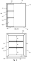
- Figs. 1a-b illustrate a schematic view of an enclosure 10 having a housing 12 forming a storage area.
- the housing 12 comprises a lower wall 12a, an upper wall 12b, two lateral side walls 12c, 12d and a rear wall 12e.
- the lower wall 12a and the upper wall 12b are both horizontally extending walls and arranged opposite each other.
- the two side walls 12c, 12d are both vertical walls arranged opposite each other.
- the housing 10 has the dimensions of a vertical length L1, a horizontal length L2 and a depth L3. The lengths of L1, L2 and L3 depend on the application for the enclosure 10.
- the enclosure 10 is arranged with a plurality of shelves 14a, 14b.
- the shelves 14a, 14b protrude out from the rear wall 12e so that objects can be placed thereon.
- the enclosure further comprises a door panel 50 configured to be arranged in a closed position and an open position.
- the door panel 50 is a sliding door panel that is slidable between the closed and open position.
- the door panel 50 is arranged with a sliding door arrangement 100, which will be discussed more in detail with reference to Figs. 3-12 .
- the enclosure 10 may for example be a cabinet, a cupboard, a locker, a closet or any other enclosure that could be arranged with a sliding door.
- the door panel 50 has a top side 52 and a lower side 54.
- the top side 52 of the door panel 50 is arranged in conjunction with the upper wall 12b of the housing 12, and the lower side 54 is arranged in conjunction with the lower wall 12a of the housing 12.
- the door panel 50 further has a first side and a second side.
- the first side faces away from the rear side 12e of the housing 12.
- At least the first side of the door panel 50 may have a finishing layer.
- the finishing layer may for example be a glass or mirror panel.
- the door panel 50 comprises a plurality of thin mirror panels, where a foil is arranged between the mirror panels.
- a T-shaped strip may be assembled in between the mirror panels so to prevent the mirror door panel from falling/sliding during cleaning of the mirror and/or enclosure 10.
- Fig. 1b is a schematic illustration of the housing 12, shown in a direction from inside the enclosure, i.e. from the rear wall 12e, where the door panel 50 and the optional shelves are removed to facilitate understanding.
- the housing 12 comprises at least a first bar 16 and a second bar 18 arranged for connection with the sliding door panel 50.
- the first and second bars 16, 18 are arranged to receive the sliding door arrangement 100 of the sliding door panel 10 in a manner that will be described more with reference to Figs. 3-12 .
- the at least two bars 16, 18 are each arranged horizontally between the two side walls 12c, 12d.
- the bars have a length L2 which substantially corresponds to the length of the lower and upper walls 12a, 12b.
- the first bar 16 is arranged at a distance D1 from the lower wall 12a and the second bar 18 is arranged at a distance D2 from the upper wall 12b.
- the first and second bars 16, 18 are arranged at a distance D3 from each other.
- the lengths D1 and D2 are the same, so that the bars 14, 16 are arranged at the same distance from the top and bottom part of the housing 12. Hence, the bars 14, 16 are symmetrically arranged. In an alternative embodiment, the distance D1 is greater than the distance D2, so that the bars 14, 16 are asymmetrically arranged.
- the bars 14, 16 may additionally be used to support the weight of the shelves.
- the enclosure 10 is preferably arranged on a wall or similar structure that has a substantially flat surface.
- Fig. 2 illustrates an exemplary environment, being a bathroom, in which the enclosure 10 could be arranged in the form of a bathroom cabinet.
- the cabinet 10 is arranged as a built-in cabinet in the bathroom wall 1 in conjunction with a shower.
- the cabinet 10 could be placed at other locations as well.
- the cabinet 10 may be arranged to store bathroom articles, such as soap, tooth paste, hair brush, toilet paper, sanitary articles etc. and/or the cabinet could be used to conceal piping, water mixer and the like.
- the cabinet 10 may be arranged in a watertight shell in which a frame, being arranged with a rear wall and four side walls that form a housing.
- the watertight shell has an access opening in which the cabinet 10 is placed.
- the access opening is arranged more or less flush with the wall or surface.
- the watertight shell is preferably used when the cabinet is to be built in a bathroom wall, for example being covered with wall tiles.
- the cabinet 10 may be arranged as a built-in cabinet in a wall 1 by the use of a sealing membrane such as paint, sealing cloth or the like.
- the cabinet 10 In the cases where the cabinet 10 is arranged as a built-in cabinet, it is possible to arrange the cabinet with connections for electrical devices in a concealed manner.
- the electrical devices may for example be lamps, fans, loudspeakers or the like.
- the storage area may also be used to conceal for example ventilation outflow.
- the cabinet is to be arranged in an environment where wet or damp articles are placed inside the cabinet, it is beneficial if at least the lower wall 12a is inclined. In this way, water will flow down to the bottom of the shelf and subsequently flow out of the storage area of the cabinet 10.
- the door panel 50 easily can be attached to and removed from the housing 12 of the cabinet 10. This is beneficial when the door panel 50 and/or the interior of the housing 12 needs to be cleaned. Having a door panel 50 which is easy to attach is also beneficial during the assembly of the cabinet 10. Moreover, it is preferred if the attachment, using a door arrangement 100, to the door panel 50 could be adjusted, both during assembly but also by the user when/if needed.
- a sliding door arrangement 100; 200; 300; 400; 500 are described herein with reference to Figs. 3-12 , which all provide a door arrangement 100; 200; 300; 400; 500 that is easily attached, removed and adjusted by the provision of having a plurality of wheels arranged on the door arrangement which are configured to interact with the bars 16, 18 arranged in the housing 12 of the enclosure.
- the interaction with the bars could be seen as the door arrangement is arranged to receive the bars.
- the door arrangement can easily be removed or attached from the housing 12 by movement of at least one handle or lever 150 in the door arrangement 100.
- the alignment of the door arrangement 100, and thus the door panel 50 can be adjusted by altering the position of at least one of the plurality of wheels.
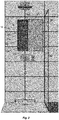
- the sliding door arrangement 100 may be constructed as a platter 110 that extends in a vertical direction.
- the platter comprises a first side 111 (as shown in Fig. 4a ) and a second side 112 (as shown in Fig. 4b ).
- first side 111 of the platter 110 faces the interior of the housing 12.
- second side 112 of the platter faces the door panel 50.
- the platter 110 further comprises a top end 113 and a lower end 114, where the top end 113 is arranged closer to the top side 52 of the door panel 50 and the lower end 113 is arranged closer to the lower side 54 of the door panel 50.
- the door arrangement comprises a plurality of wheels 122, 124, 126, 128 which are configured to interact with the first and second bars 16, 18, respectively.
- the wheels are arranged on the first side 111 of the arrangement, thus facing the bars 16, 18.
- the wheels are configured to be arranged in a first position and in a second position, as will soon be described more in detail.
- the door arrangement 100 is arranged with four wheels 122, 124, 126, 128 arranged in two pairs, as is more detailed illustrated in Figs. 4a-c .
- the two pairs can be seen as a first pair comprising wheels 122, 124 and a second pair comprising wheels 126, 128.
- the first pair of wheels 122, 124 is arranged at a position in conjunction with the top side 112 of the platter 110 whereas the second pair of wheels 126, 128 is arranged at a position in conjunction to the lower side 114 of the platter 110.
- the first pair of wheels 122, 124 comprises a first top wheel 122 and a first lower wheel 124.
- the top wheel 122 is arranged at a position closer to the top side 112 of the platter than the position of the lower wheel 124.
- the center portion of the top wheel 122 is arranged at a vertical distance D4 from the center portion of the lower wheel 124.
- the distance D4 is such that a bar 16, 18 is able to fit between the wheels 122, 124.
- the top and lower wheels are arranged with a horizontal displacement between one another.
- the center portion of the top wheel 122 is arranged at a horizontal distance D5 from the center portion of the lower wheel 124.
- the first pair of wheels 122, 124 are arranged such that when the door arrangement 100 is mounted on the first and second bar 16, 18, the first pair of wheels 122, 124 is diagonally arranged around the first bar 16.
- the first top wheel 122 is arranged above the first bar 16 and the first lower wheel 124 is arranged below the first bar 16.
- the second pair of wheels 126, 128 comprises a second top wheel 126 and a second lower wheel 128.
- the top wheel 126 is arranged at a position closer to the top side 112 of the platter than the position of the lower wheel 128.
- the center portion of the top wheel 126 is arranged at a vertical distance D4 from the center portion of the lower wheel 128.
- the top and lower wheels are arranged with a horizontal displacement between one another.
- the center portion of the top wheel 126 is arranged at a horizontal distance D5 from the center portion of the lower wheel 128.
- the second pair of wheels 126, 128 are arranged such that when the door arrangement 100 is mounted on the first and second bar 16, 18, the second pair of wheels 126, 128 is diagonally arranged around the second bar 18.
- the second top wheel 126 is arranged above the second bar 18 and the second lower wheel 128 is arranged below the second bar 18.
- the wheels 122, 124, 126, 128 are so arranged that when the door arrangement 100 is mounted on the first and second bar 16, 18, the first pair of wheels 122, 124 is diagonally arranged around the first bar 16 and the second pair of wheels 126, 128 is diagonally arranged around the second bar 18.
- the first top wheel 122 is arranged above the second lower wheel 128 and the first lower wheel 124 is arranged above the second top wheel 126.
- the wheels could switch places with each other so that that for example the first top wheel 122 is arranged above the second top wheel 126.
- This diagonal positioning of the two pairs of wheels and that they are diagonally placed in the unilateral direction has the benefit that it achieves a more stable movement of the door during opening/closing.
- Another advantage is that the door cis prevented from wobbling or tipping over as the second pair of wheels locks the door around the bar.
- the wheels 122, 124, 126, 128 may be provided with damping means 121.
- the damping means may be an O-ring or a packing.
- the damping means 121 damps the movement of the wheels on the bars 16, 18 so as to provide for a silent sliding movement.
- the second side 114 of the door arrangement comprises a track 116.
- the track is configured to receive a sliding plate 130.
- the track is thus substantially vertical.
- the sliding plate 130 is configured to slide in a vertical direction along the track 116.
- at least one of the wheels are arranged on the sliding plate 130, in order for the wheels to be movable.
- the lower wheel 124 of the first pair of wheels and the lower wheel 128 of the second pair of wheels are arranged on the sliding plate 130.
- the lower wheels 124, 128 will be moved upwards into a first position.
- the upper wheels 122, 126 of each pair are arranged directly on the platter 110 so that they are not movably arranged.
- the platter 110 is further arranged with a handle or a lever 150 that is configured to be arranged in a closed and an open position.
- the door arrangement 100 In its closed position the door arrangement 100 is securely arranged on the first and second bars 16, 18.
- the door arrangement 100, and thus the door panel 50 In its open position, the door arrangement 100, and thus the door panel 50, can easily be removed from the first and second bars 16, 18 and thus be removed from the housing 12 of the cabinet 10.
- the lever 150 allows for an easy removal of the door panel 50 from the housing 12 of the enclosure 10, this may be especially beneficial when the door panel 50 and/or the interior of the housing 12 needs to be cleaned. Furthermore, having easy removal of the door panel 50 may be beneficial during assembly and disassembly of the enclosure 10.
- the lever 150 is arranged in conjunction with the sliding plate 130.
- the lever 150 comprises a pivot slider 152 which is guided in a track 132 in the sliding plate 130.
- the track 132 in the sliding plate 130 extends in a substantially horizontal direction.
- the pivot slider 152 When the lever 150 is moved from an open position to a closed position, the pivot slider 152 is moved in its track 132 in an opposite direction than when the lever is moved in the opposite way. The movement of the pivot slider 152 forces the sliding plate 130 to move upwards, so that the lower wheels 124, 128 move upwards.
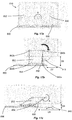
- Fig. 4b illustrates a situation where the lever 150 is in a closed position.
- the wheels are arranged in a first, upper position. In the first position, the wheels are arranged such that they are in close conjunction with a respective bar 16, 18.
- the pivot slider 152 of the lever 150 is arranged in a self-locked position since its offset the natural axis in a similar manner as in a knee joint.
- Fig. 4c a situation where the lever 150 is moved from a closed position to an open position is shown.
- the wheels are moved into a second, lower position.
- at least one of the plurality of wheels is moved in a direction away from the corresponding bar 16, 18.
- the bar 16, 18 will no longer be clamped between two wheels and the door arrangement 100, and thus the door panel 50, can thus easily be removed and/or disassembled.
- the lower wheels 124, 128 of each pair are moved downwards towards the lower end of the door arrangement 100 and away from its respective bar 16, 18. Once the lower wheels 124, 128 of each pair moves away from the bars 16, 18 a gap is formed which allows the door arrangement 100 to be removed from the bars 16, 18. Hence, the vertical distance between the wheels in each pair increases when the lever 150 is moved to an open position.
- the lever 150 comprises a locking mechanism to prevent unintended movement of the lever 150.
- the locking mechanism may use a locking pin and a corresponding opening, so that the locking pin could be withdrawn from the opening in order to unlock the locking mechanism.
- the locking mechanism is a slidable button that is movable between a locked and an unlocked position. In this specific example, the sliding button is put in an unlocked position by siding the button in an upwards direction.
- the lock button may be opened by sliding the button in a downwards direction.
- the lock button may be opened by pressing in a button. Once the lock button is moved in the correct direction, the locking pin is moved such that the wheels are allowed to move. It should be appreciated that this kind of locking mechanism could be used on different embodiments irrespective of the number of wheels and their arrangement.
- the above described embodiment of the door arrangement 100 may further comprise adjustment means.
- the adjustment means may be used to alter the position of at least one of the plurality of wheels 122, 124, 126, 128.
- the adjustment means is preferably arranged to alter the position of the movable wheels, i.e. the lower wheels 124, 128 that are arranged on the sliding plate 130.
- the adjustment means is thus preferably arranged in the sliding plate 130.
- the adjustment means could be arranged on the side, top and/or bottom of the sliding plate 130. Different embodiments of adjustment means will now be described with reference to Figs. 6-8 .
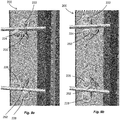
- Figs. 6a-c illustrate an embodiment of the adjustment means.
- the adjustment means 140 comprises fastening means 141 that is to be inserted into a corresponding opening 142 in the sliding plate 130.
- the wheels of the sliding plate 130 are adjusted by fastening/loosening the fastening means, so that the position of the wheels are altered.
- the fastening means 141 and the opening 142 are preferably arranged on the side of the sliding plate 130 so that the wheels can be adjusted from the side of the sliding door 100.
- the fastening means 141 is a self-tapping screw.
- the self-tapping screw is preferably a thread-forming self-tapping screw.
- the screw may for example be a PT-screw.
- the eccentric disc 143 is made of a plastic material. Once the self-tapping screw is fastened in the plastic disc, the self-tapping screw 141 taps grooves as it is driven through the material of the disc 143.
- Fig. 7 illustrates an alternative embodiment of the adjustment means. This embodiment differs from that described with relation to Figs. 6a-c in that the fastening means 144 is a metric screw and that the eccentric disc 145 has a metric thread.
- the metric screw 144 may for example be a MC6L M5x12 screw. The screw is thus engaging with the threaded surface of the eccentric disc 145.
- Figs. 8a-b illustrates yet a further embodiment of the adjustment means.
- a fastening means 147 is arranged to be received in an opening 148 in the sliding plate 130.
- the opening 148 is arranged on the top side of the sliding plate 130, to allow for adjustment from the top side of the sliding plate 130.
- the adjustment means further comprises a sliding block 149.
- the opening 148 is arranged in the sliding block 149, so that the position of the sliding block alters when the fastening means is fastened/loosened in the opening 148.
- the fastening means may be a screw. A linear motion of the sliding block, and thus the wheel connected to it, will occur during adjustment.
- FIG. 9a-b Another embodiment of the sliding door arrangement 200 is shown in Figs. 9a-b .
- the door arrangement 200 has four wheels 222, 224, 226, 228 diagonally arranged in two pairs and two levers 250, 252, one lever for each pair of wheels.
- the sliding door arrangement 200 may have the form of a platter 210 that extends in a vertical direction.
- the platter comprises a first side 211 and a second side 212.
- the first side 211 of the platter 210 faces the interior of the housing 12.
- the second side 212 of the platter 210 faces the sliding door panel 50.
- the platter 210 further comprises a top end 213 and a lower end 214, where the top end 213 is arranged closer to the top side 202 of the door panel 50 and the lower side 214 is arranged closer to the lower side 204 of the door panel 50.
- the door arrangement comprises a plurality of wheels 222, 224, 226, 228 which are configured to interact with the first and second bars 16, 18, respectively.
- the wheels are arranged on the first side 212 of the platter 210, thus facing the bars 16, 18.
- the wheels may be configured to be arranged in a first position and in a second position, as will soon be described more in detail.
- the door arrangement 200 is arranged with four wheels 222, 224, 226, 228 arranged in two pairs.
- the two pairs can be seen as the first pair comprising wheels 222, 224 and the second pair comprising wheels 226, 228.
- the first pair of wheels 222, 224 is arranged at a position in conjunction with the top side 112 of the platter 110 whereas the second pair of wheels 226, 228 is arranged at a position in conjunction with the lower side 214 of the platter 110.
- the first pair of wheels 222, 224 comprises a first top wheel 222 and a first lower wheel 224.
- the top wheel 222 is arranged at a position closer to the top side 112 of the platter than the position of the lower wheel 224.
- the center portion of the top wheel 222 is arranged at a vertical distance D4 from the center portion of the lower wheel 224.
- the distance D4 is such that a bar 16, 18 is able to fit between the wheels 222, 224.
- the top and lower wheels are arranged with a horizontal displacement between one another.
- the center portion of the top wheel 222 is arranged at a horizontal distance D5 from the center portion of the lower wheel 224.
- the first pair of wheels 222, 224 is arranged such that when the door arrangement 200 is mounted on the first and second bar 16, 18, the first pair of wheels 222, 224 is diagonally arranged around the first bar 16.
- the first top wheel 222 is arranged above the first bar 16 and the first lower wheel 224 is arranged below the first bar 16.
- the first pair of wheels 222, 224 is connected to each other by a first connecting member 260 comprising a first lever 250.
- the lever 250 will soon be described more in detail.
- the second pair of wheels 226, 228 comprises a second top wheel 226 and a second lower wheel 228.
- the top wheel 226 is arranged at a position closer to the top side 112 of the platter than the position of the lower wheel 228.
- the center portion of the top wheel 226 is arranged at a vertical distance D4 from the center portion of the lower wheel 228.
- the top and lower wheels are arranged with a horizontal displacement between one another.
- the center portion of the top wheel 226 is arranged at a horizontal distance D5 from the center portion of the lower wheel 228.
- the second pair of wheels 226, 228 is arranged such that when the door arrangement 200 is mounted on the first and second bars 16, 18, the second pair of wheels 226, 228 is diagonally arranged around the second bar 18.
- the second top wheel 226 is arranged above the second bar 18 and the second lower wheel 228 is arranged below the second bar 18.
- the second pair of wheels 226, 228 is connected to each other by a second connecting member 262 comprising a second lever 252.
- the second lever 252 will soon be described more in detail.
- the wheels 222, 224, 226, 228 are so arranged that when the door arrangement 200 is mounted on the first and second bar 16, 18, the first pair of wheels 222, 224 is diagonally arranged around the first bar 16 and the second pair of wheels 226, 228 is diagonally arranged around the second bar 18.
- the first top wheel 222 is arranged above the second lower wheel 228 and the first lower wheel 224 is arranged above the second top wheel 226.
- the wheels could switch places with each other so that that for example the first top wheel 222 is arranged above the second top wheel 226.
- the wheels 222, 224, 226, 228 may be provided with damping means 121.
- the damping means may be an O-ring or a packing.
- the damping means 121 damps the movement of the wheels on the bars 16, 18 so as to provide for a silent sliding movement.
- each pair of wheels is arranged with a respective lever 250, 252.
- Each lever 250, 252 is configured to be arranged in a closed and an open position. When both levers 250, 252 are arranged in their closed positions the door arrangement 200 is securely arranged on the first and second bars 16, 18. When both levers 250, 252 are arranged in their open positions, the door arrangement 200, and thus the door panel 50, can easily be removed from the first and second bars 16, 18 and thus be removed from the housing 12 of the enclosure 10.
- Fig. 9a illustrates a situation where the levers 250, 252 are in a closed position.
- the wheels are arranged in a first position. In a first position, the wheels are arranged such that they are in close conjunction with a respective bar 16, 18.
- Fig. 9b a situation where the levers 250, 252 are moved from a closed position to an open position is shown.
- the wheels are moved into a second position. In the second position, at least some of the plurality of wheels are moved in a direction such that an increased distance is formed between the wheels of the pair and the corresponding bar 16, 18. Due to the distance formed, the bar 16, 18 will no longer be clamped between two wheels and the door arrangement 200 can thus easily be removed and/or disassembled.
- both the wheels 222, 224 of the first pair of wheels are moved into a second position when their corresponding lever 250 is moved into an open position.
- the wheels 222, 224 are arranged in their second position, the wheels are arranged on the same vertical axis. Hence, the wheels are no longer diagonally arranged around the bar 16. In this position the distance between the wheels 222, 224 and the bar 16 is greater than when the wheels are arranged in diagonal.
- both the wheels 226, 228 of the second pair of wheels are moved into a second position when their corresponding lever 252 is moved into an open position.
- the wheels 226, 228 are arranged in its second position, the wheels are arranged on the same vertical axis. Hence, the wheels are no longer diagonally arranged around the bar 18. In this position the distance between the wheels 226, 228 and the bar 16 is greater than when the wheels are arranged in diagonal.
- the levers 250, 252 may be arranged with locking means to prevent unintended movement of the levers 250, 252 and/or the wheels.
- the locking means may be the same or similar to the locking means described with reference to Fig. 5 .
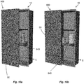
- FIG. 10a-b Yet another embodiment of a sliding door arrangement 300 is shown in Figs. 10a-b , having four wheels 322, 324, 326, 328 arranged in two pairs, where the wheels in each pair are arranged in parallel to each other.
- the wheels 322, 324, 326, 328 are arranged in between the two bars 16, 18.
- a top pair of wheels 322, 324 is arranged below the top bar 16, and a second pair of wheels 326, 328 is arranged above the lower bar 18.
- the second pair of wheels 326, 328 is arranged in connection with a lever 350.
- the sliding door arrangement 300 may be constructed as a platter 310 that extends in a vertical direction as described in relation to Figs. 9a-b .
- the arrangement comprises a plurality of wheels 322, 324, 326, 328 that are configured to interact with the first and second bars 16, 18, respectively.
- the wheels are arranged on the first side 311 of the platter 310, thus facing the bars 16, 18.
- the wheels may be configured to be arranged in a first position and in a second position, as will soon be described more in detail.
- the door arrangement 300 is arranged with four wheels 322, 324, 326, 328 arranged in two pairs.
- the two pairs can be seen as a first pair comprising wheels 322, 324 and a second pair comprising wheels 326, 328.
- the first pair of wheels 322, 324 is arranged at a position in conjunction to the top side of the door arrangement whereas the second pair of wheels 326, 328 is arranged at a position in conjunction to the lower side of the door arrangement 300.
- the first pair of wheels 322, 324 comprises a first wheel 322 and a second wheel 324.
- the first and second wheel 322, 324 are arranged adjacent to each other on the same horizontal axis.
- the first and second wheel 322, 324 are thus arranged on the same horizontal axis, being parallel to each other.
- the first pair of wheels 322, 324 is arranged such that when the door arrangement 300 is mounted on the first and second bar 16, 18, the first pair of wheels 322, 324 is arranged on the bottom surface of the first bar 16. The wheels are thus arranged below the bar 16.
- the first pair of wheels 322, 324 is connected to each other by a first connecting member 360.
- the connecting member 360 may be any type of member that connects the two wheels 322, 324.
- the member may for example be a rectangular plate arranged on the door arrangement 300.
- the second pair of wheels 326, 328 comprises a first wheel 326 and a second wheel 328.
- the first and second wheel 322, 324 are arranged adjacent to each other on the same horizontal axis.
- the first and second wheel 322, 324 are thus arranged on the same horizontal axis, being parallel to each other.
- the first pair of wheels 322, 324 are arranged such that when the door arrangement 300 is mounted on the first and second bar 16, 18, the first pair of wheels 322, 324 is arranged on the top surface of the second bar 18.
- the wheels are thus arranged above the bar 18.
- the two pairs of wheels can thus be seen as being arranged inside the two bars 16, 18.
- the second pair of wheels 326, 328 is connected to each other by a second connecting member 362 comprising a lever 350.
- the lever 350 is configured to be arranged in a closed and an open position. When the lever 350 is arranged in its closed position the door arrangement 300 is securely arranged on the first and second bars 16, 18. When the lever 350 is arranged in its open position, the door arrangement 300 can easily be removed from the first and second bars 16, 18 and thus be removed from the housing 12 of the cabinet 10.
- the lever may be a hinged member than can be moved from a position being arranged in parallel with the vertical axis of the door arrangement 300 to a position being perpendicular to said first position.
- Fig. 10a illustrates a situation where the lever 350 is in a closed position.
- the second pair of wheels 326, 328 is arranged in a first position.
- the second pair of wheels 326, 328 is arranged such that they are in close conjunction to the bar 18.
- the wheels are pushing outwards and are thus fixated between the bars.
- a situation where the lever 350 is moved from a closed position to an open position is shown.
- the wheels 326, 328 of the second pair are moved into a second position.
- the wheels 326, 328 of the second pair are moved in a direction such that an increase distance is formed between the wheels and the lower bar 18.
- said direction is upwards in a direction towards the upper bar 16.
- the wheels 326, 328 are moved upwards by the lever pressing them up. Due to the distance formed, the bars 16, 18 will no longer be clamped outside the two pairs of wheels and the door arrangement 300 can thus easily be moved.
- FIG. 11a-b A similar embodiment of a door arrangement 400 is shown in Figs. 11a-b .
- the difference compared to the embodiment shown in Figs. 11a-b is the arrangement of the wheels, and thus also the arrangement of the lever.
- the first pair of wheels 422, 424 is arranged such that when the door arrangement 400 is mounted on the first and second bars 16, 18, the first pair of wheels 422, 424 is arranged on the top surface of the first bar 16. The wheels are thus arranged above the bar 16.
- the first pair of wheels 422, 424 are connected to each other by a first connecting member 460.
- the second pair of wheels 426, 428 are arranged such that when the door arrangement 400 is mounted on the first and second bar 16, 18, the second pair of wheels is arranged on the bottom surface of the second bar 18. The wheels are thus arranged below the bar 18. The two pairs of wheels can thus be seen as being arranged outside of the two bars 16, 18.
- the second pair of wheels 426, 428 is connected to each other by a second connecting member 462 comprising a lever 450.
- Fig. 11a illustrates a situation where the lever 450 is in a closed position.
- the second pair of wheels 426, 428 are arranged in a first position.
- the second pair of wheels 426, 428 are arranged such that they are in close conjunction to the bar 18.
- a situation where the lever 450 is moved from a closed position to an open position is shown.
- the wheels 426, 428 of the second pair are moved into a second position.
- the wheels 426, 428 of the second pair are moved in a direction such that an increased distance is formed between the wheels and the lower bar 18.
- said direction is downwards in a direction away from the lower bar 18.
- the wheels 426, 428 are moved downwards by the lever pressing them down. Due to the distance formed, the bars 16, 18 will no longer be clamped between two pair of wheels and the door arrangement 400 can thus easily be moved.
- FIGs. 12a-b A further embodiment is shown in Figs. 12a-b , where the door arrangement 500 is arranged with only three wheels 522, 526, 528.
- a top wheel 522 is arranged above the upper bar 16, and a pair of wheels 526, 528 is arranged such that when the door arrangement 500 is mounted on the first and second bar 16, 18, the pair of wheels 526, 528 is diagonally arranged around the second bar 18.
- the top wheel 526 of the pair is arranged above the second bar 18 and the lower wheel 528 of the pair is arranged below the second bar 18.
- the diagonal arrangement of wheels that has been described in detail with reference to other embodiments is applicable for this pair of wheels as well.
- the top wheel 522 is connected to the door arrangement 500 by a first connecting member 560 comprising a first lever 550.
- the lever 550 may be arranged in a closed position (as shown in Fig. 12a ) and an open position (as shown in Fig. 12b ).
- the pair of wheels 526, 528 is arranged in conjunction with a second connecting member 562 comprising a second lever 552.
- the second lever 552 may be arranged in a closed position (as shown in Fig. 12a ) and an open position (as shown in Fig. 12b ).
- Fig. 12a illustrates a situation where the levers 550, 552 are in a closed position.
- the wheels are arranged in a first position. In a first position, the wheels are arranged such that they are in close conjunction with a respective bar 16, 18.
- Fig. 12b a situation where the levers 550, 552 are moved from a closed position to an open position is shown.
- the wheels are moved into a second position. In the second position, at least some of the plurality of wheels are moved in a direction such that an increased distance is formed from between the wheels of the pair and the corresponding bar 16, 18. Due to the distance formed, the bar 16, 18 will no longer be clamped between two wheels and the door arrangement 500 can thus easily be moved.
- Figs. 13-14 show an embodiment of a door arrangement 600 for an enclosure 610.
- the door arrangement uses a solution having a sliding block 620 and at least one hinged arm 650 instead of the use of a plurality of wheels.
- the at least one hinged arm 650 may be seen as a rigid and oblong connecting means, for connecting the sliding block with the door panel 50.
- the door arrangement 600 thus connects the door panel 50 to the enclosure 10.
- the enclosure may for example be a cabinet, a cupboard, a locker, a closet or any other enclosure that could be arranged with a sliding door.
- the enclosure 10 is arranged with a plurality of horizontal bars 614a-b.
- the horizontal bars may be seen as rails 614a-b.
- the rails 614a-b may be arranged on the outer end of one or more shelves of the enclosure 10.
- the enclosure 10 is arranged with a first rail 614a and a second rail 614b, wherein the first rail 614a is arranged in a position above the second rail 614b.
- the rails 614a-b are configured to receive a sliding block 620 being part of a door arrangement that connects the door arrangement 600 to the rails 614a-b in the enclosure 10.
- the sliding block 620 is configured to be slid along the rails 614a-b between an open position and a closed position.
- Fig. 13a shows an embodiment with the door arrangement 600 in a fully open position.
- the door arrangement 600 is moved away from the interior of the enclosure 10 so that a user may have access to the articles arranged in the enclosure 10.
- Fig. 13b shows an embodiment where the door arrangement 600 is in a position where it is almost closed.
- the door arrangement 600 has been moved from its fully open position into an almost closed position by the movement as shown by the arrow denoted A.
- a sliding block 620 is shown in more detail, where the outer structures have been hidden for facilitate understanding.
- the sliding block 620 has a vertically elongated structure.
- the vertically elongated structure spans across at least two rails 614a-b.
- the sliding block comprises a first end 620a and a second end 620b.
- the first end 620a connects with the first rail 614a and the second end 620a connects with the second rail 614b.
- the sliding block 620 may comprise a plurality of block attachment points 660a-c.
- the block attachment points 660a-c are adapted to hingedly receive the at least one arm 650.
- the block attachment points 660 may be arranged on both the first and second end 620a-b of the sliding block 620.
- the block attachment points 660a-d may be arranged near the edges of each end 620a-b. In the embodiment shown in Fig. 14a , two block attachment points 660a-b are arranged on the first end 620a and two block attachment points 660c-d are arranged on the second end 620b of the sliding block 620.
- the sliding block 620 comprises two or more units. Each sliding block unit connects with one of the rails 614a-b.
- the sliding block units may be arranged to move horizontally along the rails 614a-b in tandem with each other. This may be achieved through a vertical symmetry of each unit's connection to the at least one arm 650.
- the sliding block 620 is connected to at least one hinged arm 650.
- the arrangement comprises a first arm 650 and a second arm 652.
- the first and second arms 650, 652 both have a vertically elongated structure.
- the vertically elongated structure spans across at least two rails 614a-b.
- Each hinged arm 650, 652 comprises a first end 650a, 652a and a second end 650b, 652b.
- the first end 650a, 652a of the arms connects with the first end of the sliding block 620a.
- the second end 650b, 652b connects with the second end 620b of the sliding block 620.
- the hinged arms 650a, 650b are arranged so that they are parallel to each other.
- the arms 650, 652 may comprise a plurality of arm attachment points 662.
- the arm attachment points 662 may be arranged on both the first and second ends 650a, 652a, 650b, 652b of the arms 650, 652.
- the arm attachment points 662 may be arranged near the edges of each end 650a, 652a, 650b, 652b.
- the first end of the arms 650, 652 comprise two arm attachment points 662 and the second end of the arms 650, 652 comprise two arm attachment points 662.
- the first arm 650 is C-shaped. The shape is preferred since it does not block access to the enclosure 10 from one side.
- the first arm 650 is preferably used as the hinged arm 650 closest towards the opening of the enclosure 10 when the enclosure 10 is in an open state. In this way, more of the enclosure 10 will be accessible in an open state.
- Figs. 14b-c show the enclosure 10 in an open state.
- the second arm 652 is rectangle shaped.
- the second arm is preferably used as the hinged arm 650 closest towards the edge of the enclosure 10 when the enclosure 10 is in an open state.
- each hinged arm 650, 652 is divided into two or more arm units.
- the arm units have an oblong structure which extends between the sliding block 620 or sliding block units.
- Each arm unit corresponds to one hinged arm 650 and one cabinet shelf. These determine the arm unit's horizontal and vertical placement, respectively.
- Each arm unit connects with a sliding block 620 or sliding block unit.
- each arm unit corresponding to the same hinged arm 650 should connect with the same block 620.
- the arm units may be arranged to move in tandem with each other. This may be achieved through a vertical symmetry of each arm unit's connection to the sliding block 620 or sliding block units.
- the hinged arms would be replaced with four arm units, one for each block attachment point.
- Fig. 14c where it is shown that the at least one arm 650, 652 is hingedly connected to a mounting plate 654.
- the mounting plate 654 is the interface connecting the door arrangement to the door panel 50.
- the door arrangement 600 is attachable to the mounting plate 654.
- the mounting plate 654 is arranged to receive the door panel 50.
- the mounting plate 654 is arranged to be parallel to the sliding block 620 at all times during movement. Furthermore, when mounted the door panel 50 will be parallel to the sliding block 620.
- the mounting plate 654 is hingedly connected to the at least one arm 650, 652.
- the mounting plate 654 may be horizontally oblong and extending between the arms 650, 652.
- the mounting plate 654 may also be vertically oblong and extend between the lower and upper ends of the arms 650, 652.
- the mounting plate 654 is arranged between the outer edges of the arms 650a, 650b.
- the mounting plate 654 may be arranged with a plurality of plate attachment points 664. These plate attachment points are configured to be connected with the arm attachment points 662.
- the plate attachment points 664 have the same distance between them as the block attachment points 660 of the sliding block 620. This keeps the arms 650a, 650b parallel during sliding and rotation. This also keeps the mounting plate 654 and consequently the door panel 50 parallel to the sliding block 620.
- the mounting plate 654, the sliding block 620 and the hinged arms 650a, 650b forms a horizontal parallelogram.
- the door panel 50 is directly arranged on the arms 650, 652.
- the door panel 50 is hingedly connected to at least one arm 650, 652.
- Fig. 14d shows the arms 650 652 of Fig. 14b in a closed position.
- the first and second arms 650, 652 are arranged such that they are parallel to the outer edge of the shelves.
- the first and the second arms 650, 652 are arranged in the same plane.
- Figs. 14a-d show two shelves with rails 614a-b. There are additional possible embodiments with one or three or more shelves with rails 614a-b. In the embodiment with only one rail 614, sliding blocks 620 and block units are equivalent, the same applies to arms 650 and arm units. In embodiments with three or more rails 614, the elongated structure of the sliding block 620 and the hinged arms 650 may span across more than two rails. There may also be different sliding blocks and hinged arms that span across two or more rails that are different from the rails that other sliding blocks or hinged arms span across. The sliding blocks may also span across more than three rails and only connect to a subset of the spanned rails 614.
- the arms 650, 652 are hingedly connected to at least the sliding block 620.
- the hinged connection to the sliding block 620 and/or the mounting plate 654 and/or the door arrangement 600 may be fastened by a fastening means, such as a screw or nail or bolt.
- the hinged connection may also be fastened by an adhesive such as glue or epoxy.
- the sliding block 620 is slidable along the rail 614. The slidability may be achieved using bearings, low friction surface connections or wheels.
- the arms 650, 652 may be straight or angled.
- the arms 650, 652 are rotatable between an open and a closed position.
- the arms 650, 652 may be arranged to be rotatable along a specific movement path.
- the arms 650, 652 may use a parallelogram movement. In the open position the arms 650, 652 may be extending outwards. In a closed position the arms 650, 652 may be extending parallel to the outer edge of the shelves.
- a door arrangement 600 for attaching a door panel 50 to an enclosure 10 being arranged with at least one bar 614a,b.
- the door arrangement 600 comprises at least one sliding block 620 arranged to be movable along the at least one bar 614a,b of the enclosure 10 between a first position and a second position.
- the door arrangement further comprises at least one hinged arm 650, 652 arranged to be hingedly connected to said at least one sliding block 620.
- the at least one hinged arm is either directly or indirectly connected to the door panel 50 so as to facilitate movement of the door panel 50.
- Figs. 15a-b show yet an alternative embodiment of a door arrangement.
- the enclosure 10 is not arranged with horizontal rails being configured to receive a sliding block.
- the door arrangement comprises at least one hinged arm 750, 752.
- the door arrangement 700 comprises a first hinged arm 750 and a second hinged arm 752.
- the arms 750, 752 are at their first ends 750a, 752a connected to the door panel 50, either directly or indirectly, and at their other, second, ends 750b, 752b connected to the enclosure 10.
- first hinged arm 750 is straight and the second hinged arm 752 is arranged with an angled portion.
- the angle of the angled portion of the second arm 752 is preferably around 80-100 degrees. In one embodiment, the angle is 85-95 degrees, and more preferably 90 degrees.
- Fig. 15a shows an enclosure according to one embodiment with the door arrangement 700 in an open position.
- Fig. 15b shows an above view of the door arrangement 700 in a semi-open position. The direction of movement of the door arrangement 700 from an open position towards a closed position is shown by an arrow denoted B. If the door arrangement 700, and thus the door panel 50, in Fig. 15b were to be pushed to the left, it would reach an open position.
- the straight arm 750 extends towards the left.
- the door arrangement In an open position the door arrangement is shifted fully to the left of the enclosure 10, allowing for full access to the enclosure.
- a closed position the straight arm 750 and the side of the angled arm 752 attached to the door arrangement 700 extends towards the right.
- the hinged arms 750, 752 have an elongated structure.
- the elongated structure spans between the door panel 50 and the enclosure 10 when mounted.
- each hinged arm 750, 752 comprises a first end 750a, 752a and a second end 750b, 752b.
- the second end 750b, 752b of each hinged arm 750, 752 connects with the enclosure 10.
- first end 750a, 752a may connect with a mounting plate 754 attached to the door arrangement 700.
- hinged arms 750, 752 are connected to the door panel 50 directly without the use of a mounting plate 754.
- the hinged arms 750, 752 are arranged to be able to move in parallel to each other.
- the first ends 750a, 752a are horizontally separated a distance equal to the horizontal separation of the second ends 750b, 752b.
- This separation is also parallel to each other and preferably also parallel to the edge of the enclosure 10.
- This parallelogram keeps the door panel 50 parallel to the enclosure 10 at all times.
- the door arrangement 700 may be shifted further to one side when the arms 750, 752 are in an open position.
- the door arrangement 700 is preferably opened towards the side with the angled arm 752.
- the arms 750, 752 are preferably arranged with the straight arm 750 in the center of the enclosure and the angled arm 752 close to a wall of the enclosure.
- the angled arm 752 is preferably angled towards the wall it is close to.
- the straight arm 750 is preferably attached to the door panel 50 close to the edge opposite to the direction of the attachment of the angled arm 752.
- the angled arm 752 may be attached to the center of the door panel 50.
- the position of the angle of the angled arm 752 may depend on how deep into the enclosure the arm 752 is fastened. In a preferred embodiment, the angled arm 752 abuts two sides of the enclosure in its open position. This means that different sides of the angle of the angled arm 752 is then parallel to the wall of the enclosure and the front of the enclosure. This may be achieved by placing the angle of the angled arm 752 at a distance equal to the distance from the fastener of the angled arm 752 to the front edge of the enclosure.
- Figs. 15a-b discloses a door arrangement for attaching a door panel 50 to an enclosure 10.
- the door arrangement comprises at least one hinged arm 750, 752 arranged to be hingedly connected to the enclosure 10, and a door panel 50 arranged to be attached to said at least one hinged arm 750, 752.
- the door arrangement may further comprise at least one mounting plate 754 arranged to be hingedly connected to said at least one hinged arm 750, 752.
- the door arrangement 700 is thus arranged to be attached to said at least one mounting plate 754.
- the at least one hinged arm is either directly or indirectly connected to the door panel so as to facilitate movement of the door panel.
- the door arrangement comprises two hinged arms 750, 752, wherein at least one 752 of the said at least two hinged arms 750, 752 is angled.
- Figs. 16-18 show yet another embodiment of a door arrangement for connecting a door panel 50 to an enclosure 10. This embodiment is similar to the one discussed with reference to Figs. 15a-b , and differs in that it further comprises a rotatable shelf 840.
- the rotatable shelf 840 is attached to one or more of the hinged arms 850, 852.
- the rotatable shelf 840 rotates with the rotation of the arms 850, 852.
- the rotatable shelf 840 may be shaped like a circular sector.
- the central angle A (as seen in Figs. 17-18 ) of the circular sector may be between 90 and 270 degrees.
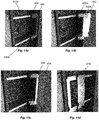
- Figs. 16a-b show a semi-open enclosure 10.
- the door arrangement 800 When the door arrangement 800 is in a fully open position, the arrangement is shifted towards the left and the rotatable shelf 840 has rotated further and is fully accessible to the user.
- Figs. 17a-c show a top down schematic view of the arrangement with the rotatable shelf 840.
- the size and the central angle of the rotatable shelf 840 depends on the dimensions of the enclosure and the position of the angle of the angled arm 852.
- the figures show the enclosure in different stages moving between a closed position to an open position.
- Fig. 17a shows an example of the door arrangement 800 in a closed position.
- the straight arm 850 is extended towards the right.
- the corners of the circular sector are facing the door panel 50.
- the door arrangement 800 abuts the enclosure.
- the door arrangement 800 is parallel to the enclosure.
- Fig. 17b shows an example of the door arrangement 800 in a semi-open position.
- the door arrangement 800 has been pushed left a distance of D7 and away from the enclosure a distance of D6.
- a user has access to some parts of the shelves and one corner of the rotatable shelf 840.
- the distance D6 is approximately 50-100 cm, and more specifically around 75 cm.
- the distance D6 depends on the length and fastening position of the straight arm 850.
- the distance D6 increases as the straight arm 850 increases in length or is fastened closer to the front of the enclosure.
- the angled arm 852 needs to be dimensioned to be able to extend the entire length of the straight arm 850 in order for the two arms 850, 852 to be mounted and moved in parallel.
- the distance D7 is approximately 60-110 cm, and more specifically around 85 cm.
- the distance D7 depends on where the arms 850, 852 are fastened to the door panel 50.
- the straight arm 850 should be fastened close to the edge of the door panel 50.
- the door panel 50 should however fully cover the enclosure in a closed position, which limits the fastening position of the straight arm 850 and therefore also D7.
- Fig. 17c shows an example of the door arrangement 800 in an open position.
- the door arrangement 800 abuts the angled arm 852.
- the angled arm 852 partly abuts the enclosure.
- the door arrangement 800 is parallel to the enclosure.
- the door arrangement is shifted fully to the left by the distance D9.
- the enclosure is a distance of D8 away from the enclosure edge.
- the distance D8 is approximately 10-40 cm, and more specifically around 25 cm.
- the distance D8 is determined by the thickness of the arms 850, 852 and their mounting plate 810. This distance is preferably small, however the arms 850, 852 and their mounting plate 810 need to be thick enough to be sturdy. D8 may be increased by lengthening the arms 850, 852, however this is not preferable.
- the distance D9 is approximately 160-200 cm, and more specifically around 180 cm.
- the distance D9 depends on where the arms 850, 852 are fastened to the door panel 50 and the length of the arms 850, 852.
- D9 is preferably large as it allows a user to have access to the enclosure.
- the arms 850, 852 are preferably not lengthened and there is a limit to where the arms 850, 852 may be fastened to the door panel 50.
- the straight arm 850 extends fully to the left.
- the angled arm 852 extend its side attached to the door arrangement 800 towards the left parallel to the door arrangement 800 and its side attached to the enclosure would extend towards the door arrangement 800.
- One or both of its sides abuts the enclosure.
- the rotatable shelf 840 is fully rotated. A user has access to the entire rotatable shelf 840 and enclosure.
- Figs. 18a-c show a similar sequence of the enclosure in different stages moving between a closed to open position as in Figs. 17a-c , however in this embodiment the arms 850, 852 are fastened to a different part of the shelves.
- the fasteners are closer towards the door panel 50.
- the rotatable shelf 840 may be made larger.
- the central angle of the circular sector may also be smaller.
- the door panel 50 may extend further away from the enclosure at its maximum distance.
- the angle of the angled arm 852 is preferably to be positioned differently to allow for a fully open door panel 50 position.
- Fig. 18a shows the door arrangement 800 in a closed position.
- the central angle of the circular sector is smaller and less than 180 degrees. This means that its corners now point towards the walls of the enclosure when the door arrangement 800 is in a closed position. This wastes less space and allows for a larger rotatable shelf 840.
- the central angle is preferably approximately 150-210 degrees, and more specifically around 175 degrees.
- Fig. 18b shows the door arrangement 800 in a semi-open position.
- the distance D6 is approximately 80-120 cm, and more specifically around 100 cm.
- the distance D6 is larger than in Fig. 17b since the arms 850, 852 are fastened closer to the front of the enclosure. This also means that the center of the rotatable shelf 840 is closer to the front of the enclosure, allowing for easier access to it in Fig. 18b .
- the distance D7 is unchanged from Fig. 17b as the position of where the arms 850, 852 are fastened to the door panel 50 is unchanged.
- Fig. 18c shows the door arrangement 800 in an open position.
- the distance D9 is approximately 180-220 cm, and more specifically around 200 cm.
- the distance D9 is increased from Fig. 17c because the arms 850, 852 are fastened closer to the front of the enclosure. This means that the enclosure is more accessible.
- the distance D8 is unchanged from Fig. 17c as the thickness of the arms 850, 852 and their mounting plate 810 are unchanged.
- a further distance D10 represents the distance which the rotatable shelf 840 is extended beyond the front of the enclosure.
- the distance D10 is approximately 80-120 cm, and more specifically around 100 cm. This distance D10 is much larger than in Fig. 17c and it depends on how close the arms 850, 852 are fastened to the front of the enclosure and the size of the enclosure. This means that the rotatable shelf 840 is fully accessible in an open position.
- the door arrangement 800 comprises at least one hinged arm 850, 852 arranged to be hingedly connected to the enclosure 10, and a door panel 50 arranged to be attached to said at least one hinged arm 750, 752.
- the door arrangement 800 may further comprise at least one mounting plate 854 arranged to be hingedly connected to said at least two hinged arms 850, 852.
- the door panel 50 is thus arranged to be attached to said at least one mounting plate 854.
- the at least one hinged arm is thus either directly or indirectly connected to the door panel so as to facilitate movement of the door panel.
- the door arrangement may further comprise a rotatable shelf 840 attached to the at least one hinged arm 850, 852 and configured to follow the rotational movement of said at least one hinged arm 850, 852.
Landscapes
- Engineering & Computer Science (AREA)
- Mechanical Engineering (AREA)
- Handcart (AREA)
Abstract
Description
- The present invention relates to a space efficient door arrangement for a sliding door panel being attached to an enclosure, such as a cabinet.
- Sliding door panels for enclosures are often used in situations when there are space restrictions since a sliding door panel is more space efficient than hinged door panels. Cabinets being arranged in bathrooms, which are often small rooms, are thus ideally arranged with some kind of sliding door panel. If the cabinet is arranged in conjunction to water, it is beneficial if the bottom surface of the cabinet is inclined so as to facilitate an efficient drainage of water. However, many of the prior art cabinets have problems relating to this inclined bottom surface. There is thus a need to develop a door arrangement that can be used together with a cabinet having a sloped surface.
- Moreover, in space constrained environments it may be difficult to reach the hinges or other holding means that are holding up the door panel and/or to remove the door panel from its arrangement in the cabinet. Removing the door panel from its arrangement in the cabinet may be beneficial in order to efficiently clean the door panel and/or the interior of the cabinet.
- Furthermore, during installation and during normal use it is beneficial if the door panel can be easily adjusted so that the position of the door panel in relation to the cabinet can be altered.
- There is thus a need to develop a door arrangement that allows for easy attachment/removal of the door panel as well as easy adjustment.
- An idea of the present invention is to provide a sliding door arrangement for a sliding door panel which is attached to an enclosure, wherein the arrangement is such that it allows for easy removal of the door panel from the enclosure. Moreover, the door arrangement is such that easy adjustment of the door arrangement is achieved.
- According to a first aspect, a sliding door arrangement for a sliding door panel being arranged to an enclosure is provided. The sliding door arrangement comprises a plurality of wheels being arranged to interact with at least two horizontal bars of the enclosure, wherein at least one wheel is movably arranged from a first position to a second position, and at least one lever configured to be in an open position and a closed position, wherein when the lever is put into the open position the at least one movable wheel is moved into its second position so as to facilitate removal of the door panel from the at least two bars.
- According to a second aspect, a door arrangement for a sliding door panel being attached to an enclosure having at least one bar is provided. The door arrangement comprises at least one sliding block arranged to be movable along at least one bar of the enclosure from a first position to a second position. The door arrangement further comprises at least one hinged arm arranged to be hingedly connected to said at least one sliding block. The at least one hinged arm is either directly or indirectly connected to the door arrangement so as to facilitate movement of the door panel to which the door arrangement is attached.
- According to third aspect, a door arrangement for a sliding door panel being arranged to an enclosure having at least one bar is provided. The door arrangement comprises at least one hinged arm arranged to be hingedly connected to the enclosure. The at least one hinged arm is either directly or indirectly connected to the door arrangement so as to facilitate movement of the door arrangement and thus the door panel. The door arrangement may further comprises a rotatable shelf attached to the at least one hinged arm and configured to follow the rotational movement of said at least one hinged arm.
- Further objects, features and advantages will appear from the following detailed description, with reference being made to the accompanying drawings, in which:
-
Figs. 1a-b are schematic illustrations of an enclosure having a sliding door panel and a door sliding door arrangement according to an embodiment; -
Fig. 2 is a view of an exemplary environment for the enclosure shown inFigs. 1a-b ; -
Figs. 3a-b are isometric side views of a sliding door panel being arranged with a sliding door arrangement according to one embodiment, having a lever being in a closed position (Fig. 3a ) and an open position (Fig. 3b ); -
Figs. 4a-c are schematic illustrations of a part of the sliding door arrangement shown inFigs. 3a-b in more detail. -
Fig. 5 is an isometric view of a locking member according to an embodiment; -
Figs. 6a-c are isometric views of a pair of wheels according to an embodiment; -
Fig. 7 is an isometric side view of a wheel according to an embodiment; -
Figs. 8a-b are isometric views of a pair of wheels according to an embodiment; -
Figs. 9a-b are isometric views of a door arrangement according to another embodiment having a lever being in a closed position (Fig. 9a ) and an open position (Fig. 9b ); -
Figs. 10a-b are isometric views of a door arrangement according to a further embodiment having a lever being in a closed position (Fig. 10a ) and an open position (Fig. 10b ); -
Figs. 11a-b are isometric views of a door arrangement according to yet a further embodiment having a lever being in a closed position (Fig. 11a ) and an open position (Fig. 11b ); -
Figs. 12a-b are isometric views of a door arrangement according to even a further embodiment having a lever being in a closed position (Fig. 12a ) and an open position (Fig. 12b ); -
Figs. 13a-b are isometric views of a sliding door arrangement according to one embodiment showing the door panel being in a partly open position (Fig. 13a ) and an partly closed position (Fig. 13b ); -
Figs. 14a-d are isometric views of the sliding door arrangement inFigs. 13a-b shown in more detail; -
Figs. 15a-b are isometric views of a sliding door arrangement according to one embodiment showing the door panel being in a partly open position (Fig. 15a ) and a top view of said door arrangement (Fig. 15b ); -
Figs. 16a-b are isometric views of a sliding door arrangement according to one embodiment showing the door panel being in a partly closed position (Fig. 16a ) and a partly open position (Fig. 16b ); -
Figs. 17a-c are isometric views of the sliding door arrangement ofFigs. 16a-b in more detail; and -
Figs. 18a-c are isometric views of the sliding door arrangement ofFigs. 16a-b in more detail. -
Figs. 1a-b illustrate a schematic view of anenclosure 10 having ahousing 12 forming a storage area. Thehousing 12 comprises alower wall 12a, anupper wall 12b, twolateral side walls rear wall 12e. Thelower wall 12a and theupper wall 12b are both horizontally extending walls and arranged opposite each other. The twoside walls Fig. 1b , thehousing 10 has the dimensions of a vertical length L1, a horizontal length L2 and a depth L3. The lengths of L1, L2 and L3 depend on the application for theenclosure 10. - In some embodiments, the
enclosure 10 is arranged with a plurality ofshelves 14a, 14b. Theshelves 14a, 14b protrude out from therear wall 12e so that objects can be placed thereon. - The enclosure further comprises a
door panel 50 configured to be arranged in a closed position and an open position. Thedoor panel 50 is a sliding door panel that is slidable between the closed and open position. Moreover, thedoor panel 50 is arranged with a slidingdoor arrangement 100, which will be discussed more in detail with reference toFigs. 3-12 . - The
enclosure 10 may for example be a cabinet, a cupboard, a locker, a closet or any other enclosure that could be arranged with a sliding door. - The
door panel 50 has atop side 52 and alower side 54. Thetop side 52 of thedoor panel 50 is arranged in conjunction with theupper wall 12b of thehousing 12, and thelower side 54 is arranged in conjunction with thelower wall 12a of thehousing 12. Thedoor panel 50 further has a first side and a second side. When thedoor panel 50 is arranged to thehousing 12 of theenclosure 10, by the use of a slidingdoor arrangement 100, the first side faces away from therear side 12e of thehousing 12. At least the first side of thedoor panel 50 may have a finishing layer. The finishing layer may for example be a glass or mirror panel. In one embodiment thedoor panel 50 comprises a plurality of thin mirror panels, where a foil is arranged between the mirror panels. A T-shaped strip may be assembled in between the mirror panels so to prevent the mirror door panel from falling/sliding during cleaning of the mirror and/orenclosure 10. -
Fig. 1b is a schematic illustration of thehousing 12, shown in a direction from inside the enclosure, i.e. from therear wall 12e, where thedoor panel 50 and the optional shelves are removed to facilitate understanding. Thehousing 12 comprises at least afirst bar 16 and asecond bar 18 arranged for connection with the slidingdoor panel 50. The first andsecond bars door arrangement 100 of the slidingdoor panel 10 in a manner that will be described more with reference toFigs. 3-12 . The at least twobars side walls - The bars have a length L2 which substantially corresponds to the length of the lower and
upper walls first bar 16 is arranged at a distance D1 from thelower wall 12a and thesecond bar 18 is arranged at a distance D2 from theupper wall 12b. Moreover, the first andsecond bars - In one embodiment, the lengths D1 and D2 are the same, so that the
bars 14, 16 are arranged at the same distance from the top and bottom part of thehousing 12. Hence, thebars 14, 16 are symmetrically arranged. In an alternative embodiment, the distance D1 is greater than the distance D2, so that thebars 14, 16 are asymmetrically arranged. - The
bars 14, 16 may additionally be used to support the weight of the shelves. - The
enclosure 10 is preferably arranged on a wall or similar structure that has a substantially flat surface.Fig. 2 illustrates an exemplary environment, being a bathroom, in which theenclosure 10 could be arranged in the form of a bathroom cabinet. In this embodiment thecabinet 10 is arranged as a built-in cabinet in the bathroom wall 1 in conjunction with a shower. However, it should be understood that thecabinet 10 could be placed at other locations as well. Thecabinet 10 may be arranged to store bathroom articles, such as soap, tooth paste, hair brush, toilet paper, sanitary articles etc. and/or the cabinet could be used to conceal piping, water mixer and the like. - In the situation where the
cabinet 10 is arranged as a built-in cabinet in a wall 1, or similar kind of surface, thecabinet 10 may be arranged in a watertight shell in which a frame, being arranged with a rear wall and four side walls that form a housing. The watertight shell has an access opening in which thecabinet 10 is placed. The access opening is arranged more or less flush with the wall or surface. Hence, once thecabinet 10 is arranged in the watertight shell, the cabinet is in flush with the wall or surface to which it is builtin. The watertight shell is preferably used when the cabinet is to be built in a bathroom wall, for example being covered with wall tiles. - Additionally, or alternatively, to a watertight shell the
cabinet 10 may be arranged as a built-in cabinet in a wall 1 by the use of a sealing membrane such as paint, sealing cloth or the like. - In the cases where the
cabinet 10 is arranged as a built-in cabinet, it is possible to arrange the cabinet with connections for electrical devices in a concealed manner. The electrical devices may for example be lamps, fans, loudspeakers or the like. The storage area may also be used to conceal for example ventilation outflow. - If the cabinet is to be arranged in an environment where wet or damp articles are placed inside the cabinet, it is beneficial if at least the
lower wall 12a is inclined. In this way, water will flow down to the bottom of the shelf and subsequently flow out of the storage area of thecabinet 10. - It is preferred if the
door panel 50 easily can be attached to and removed from thehousing 12 of thecabinet 10. This is beneficial when thedoor panel 50 and/or the interior of thehousing 12 needs to be cleaned. Having adoor panel 50 which is easy to attach is also beneficial during the assembly of thecabinet 10. Moreover, it is preferred if the attachment, using adoor arrangement 100, to thedoor panel 50 could be adjusted, both during assembly but also by the user when/if needed. - Different embodiments of a sliding
door arrangement 100; 200; 300; 400; 500 are described herein with reference toFigs. 3-12 , which all provide adoor arrangement 100; 200; 300; 400; 500 that is easily attached, removed and adjusted by the provision of having a plurality of wheels arranged on the door arrangement which are configured to interact with thebars housing 12 of the enclosure. The interaction with the bars could be seen as the door arrangement is arranged to receive the bars. The door arrangement can easily be removed or attached from thehousing 12 by movement of at least one handle orlever 150 in thedoor arrangement 100. Moreover, the alignment of thedoor arrangement 100, and thus thedoor panel 50, can be adjusted by altering the position of at least one of the plurality of wheels. - A first embodiment of a sliding
door arrangement 100 will now be described with reference toFigs. 3-8 . As seen inFigs. 3a-b , the slidingdoor arrangement 100 may be constructed as aplatter 110 that extends in a vertical direction. The platter comprises a first side 111 (as shown inFig. 4a ) and a second side 112 (as shown inFig. 4b ). When thearrangement 100, and thus thedoor panel 50, is arranged on thehousing 12 of theenclosure 10 thefirst side 111 of theplatter 110 faces the interior of thehousing 12. Thesecond side 112 of the platter faces thedoor panel 50. - The
platter 110 further comprises atop end 113 and alower end 114, where thetop end 113 is arranged closer to thetop side 52 of thedoor panel 50 and thelower end 113 is arranged closer to thelower side 54 of thedoor panel 50. - The door arrangement comprises a plurality of
wheels second bars first side 111 of the arrangement, thus facing thebars - In this embodiment, the
door arrangement 100 is arranged with fourwheels Figs. 4a-c . The two pairs can be seen as a firstpair comprising wheels pair comprising wheels wheels top side 112 of theplatter 110 whereas the second pair ofwheels lower side 114 of theplatter 110. - The first pair of
wheels top wheel 122 and a firstlower wheel 124. Thetop wheel 122 is arranged at a position closer to thetop side 112 of the platter than the position of thelower wheel 124. The center portion of thetop wheel 122 is arranged at a vertical distance D4 from the center portion of thelower wheel 124. The distance D4 is such that abar wheels top wheel 122 is arranged at a horizontal distance D5 from the center portion of thelower wheel 124. - The first pair of
wheels door arrangement 100 is mounted on the first andsecond bar wheels first bar 16. The firsttop wheel 122 is arranged above thefirst bar 16 and the firstlower wheel 124 is arranged below thefirst bar 16. - The second pair of
wheels top wheel 126 and a secondlower wheel 128. Thetop wheel 126 is arranged at a position closer to thetop side 112 of the platter than the position of thelower wheel 128. The center portion of thetop wheel 126 is arranged at a vertical distance D4 from the center portion of thelower wheel 128. Moreover, the top and lower wheels are arranged with a horizontal displacement between one another. The center portion of thetop wheel 126 is arranged at a horizontal distance D5 from the center portion of thelower wheel 128. - The second pair of
wheels door arrangement 100 is mounted on the first andsecond bar wheels second bar 18. The secondtop wheel 126 is arranged above thesecond bar 18 and the secondlower wheel 128 is arranged below thesecond bar 18. - Hence, the
wheels door arrangement 100 is mounted on the first andsecond bar wheels first bar 16 and the second pair ofwheels second bar 18. In this embodiment, the firsttop wheel 122 is arranged above the secondlower wheel 128 and the firstlower wheel 124 is arranged above the secondtop wheel 126. However, as is apparent, the wheels could switch places with each other so that that for example the firsttop wheel 122 is arranged above the secondtop wheel 126. - This diagonal positioning of the two pairs of wheels and that they are diagonally placed in the unilateral direction has the benefit that it achieves a more stable movement of the door during opening/closing. Another advantage is that the door cis prevented from wobbling or tipping over as the second pair of wheels locks the door around the bar.
- The
wheels bars - Turning back to
Figs. 4a-c , thesecond side 114 of the door arrangement comprises atrack 116. The track is configured to receive a slidingplate 130. The track is thus substantially vertical. The slidingplate 130 is configured to slide in a vertical direction along thetrack 116. In one embodiment, at least one of the wheels are arranged on the slidingplate 130, in order for the wheels to be movable. As shown inFigs. 3-4 , thelower wheel 124 of the first pair of wheels and thelower wheel 128 of the second pair of wheels are arranged on the slidingplate 130. When the slidingplate 130 is moved downwards, i.e. towards thelower side 114 of theplatter 110, thelower wheels plate 130 is moved upwards in the track, thelower wheels upper wheels platter 110 so that they are not movably arranged. - The
platter 110 is further arranged with a handle or alever 150 that is configured to be arranged in a closed and an open position. In its closed position thedoor arrangement 100 is securely arranged on the first andsecond bars door arrangement 100, and thus thedoor panel 50, can easily be removed from the first andsecond bars housing 12 of thecabinet 10. Thelever 150 allows for an easy removal of thedoor panel 50 from thehousing 12 of theenclosure 10, this may be especially beneficial when thedoor panel 50 and/or the interior of thehousing 12 needs to be cleaned. Furthermore, having easy removal of thedoor panel 50 may be beneficial during assembly and disassembly of theenclosure 10. - As seen in
Figs. 4a-c , thelever 150 is arranged in conjunction with the slidingplate 130. Thelever 150 comprises apivot slider 152 which is guided in atrack 132 in the slidingplate 130. Thetrack 132 in the slidingplate 130 extends in a substantially horizontal direction. - When the
lever 150 is moved from a closed position to an open position, thepivot slider 152 is moved in itstrack 132 which forces the slidingplate 130 to move downwards. When the slidingplate 130 moves downwards, thelower wheels second bar - When the
lever 150 is moved from an open position to a closed position, thepivot slider 152 is moved in itstrack 132 in an opposite direction than when the lever is moved in the opposite way. The movement of thepivot slider 152 forces the slidingplate 130 to move upwards, so that thelower wheels -
Fig. 4b illustrates a situation where thelever 150 is in a closed position. When thelever 150 is in a closed position, the wheels are arranged in a first, upper position. In the first position, the wheels are arranged such that they are in close conjunction with arespective bar pivot slider 152 of thelever 150 is arranged in a self-locked position since its offset the natural axis in a similar manner as in a knee joint. - When the
lever 150 is in a closed position so that thedoor arrangement 100 is arranged on the first andsecond bars respective bar bars respective bar bars - In
Fig. 4c , a situation where thelever 150 is moved from a closed position to an open position is shown. Once thelever 150 is moved to its open position, the wheels are moved into a second, lower position. In the second position, at least one of the plurality of wheels is moved in a direction away from the correspondingbar bar bar door arrangement 100, and thus thedoor panel 50, can thus easily be removed and/or disassembled. - In this embodiment, the
lower wheels door arrangement 100 and away from itsrespective bar lower wheels bars 16, 18 a gap is formed which allows thedoor arrangement 100 to be removed from thebars lever 150 is moved to an open position. - In some embodiments the
lever 150 comprises a locking mechanism to prevent unintended movement of thelever 150. The locking mechanism may use a locking pin and a corresponding opening, so that the locking pin could be withdrawn from the opening in order to unlock the locking mechanism. In one embodiment, as shown inFig. 5 , the locking mechanism is a slidable button that is movable between a locked and an unlocked position. In this specific example, the sliding button is put in an unlocked position by siding the button in an upwards direction. - In other embodiments the lock button may be opened by sliding the button in a downwards direction. Alternatively, or additionally, the lock button may be opened by pressing in a button. Once the lock button is moved in the correct direction, the locking pin is moved such that the wheels are allowed to move. It should be appreciated that this kind of locking mechanism could be used on different embodiments irrespective of the number of wheels and their arrangement.
- The above described embodiment of the
door arrangement 100 may further comprise adjustment means. The adjustment means may be used to alter the position of at least one of the plurality ofwheels lower wheels plate 130. The adjustment means is thus preferably arranged in the slidingplate 130. The adjustment means could be arranged on the side, top and/or bottom of the slidingplate 130. Different embodiments of adjustment means will now be described with reference toFigs. 6-8 . -
Figs. 6a-c illustrate an embodiment of the adjustment means. The adjustment means 140 comprises fastening means 141 that is to be inserted into acorresponding opening 142 in the slidingplate 130. The wheels of the slidingplate 130 are adjusted by fastening/loosening the fastening means, so that the position of the wheels are altered. The fastening means 141 and theopening 142 are preferably arranged on the side of the slidingplate 130 so that the wheels can be adjusted from the side of the slidingdoor 100. - In this embodiment, the fastening means 141 is a self-tapping screw. The self-tapping screw is preferably a thread-forming self-tapping screw. The screw may for example be a PT-screw. The eccentric disc 143 is made of a plastic material. Once the self-tapping screw is fastened in the plastic disc, the self-tapping
screw 141 taps grooves as it is driven through the material of the disc 143. -
Fig. 7 illustrates an alternative embodiment of the adjustment means. This embodiment differs from that described with relation toFigs. 6a-c in that the fastening means 144 is a metric screw and that the eccentric disc 145 has a metric thread. The metric screw 144 may for example be a MC6L M5x12 screw. The screw is thus engaging with the threaded surface of the eccentric disc 145. -
Figs. 8a-b illustrates yet a further embodiment of the adjustment means. In this embodiment a fastening means 147 is arranged to be received in anopening 148 in the slidingplate 130. In this embodiment theopening 148 is arranged on the top side of the slidingplate 130, to allow for adjustment from the top side of the slidingplate 130. The adjustment means further comprises a slidingblock 149. Theopening 148 is arranged in the slidingblock 149, so that the position of the sliding block alters when the fastening means is fastened/loosened in theopening 148. The fastening means may be a screw. A linear motion of the sliding block, and thus the wheel connected to it, will occur during adjustment. - Another embodiment of the sliding
door arrangement 200 is shown inFigs. 9a-b . In this embodiment, thedoor arrangement 200 has fourwheels levers - The sliding
door arrangement 200 may have the form of a platter 210 that extends in a vertical direction. The platter comprises a first side 211 and a second side 212. When arranged on thehousing 12 of theenclosure 10 the first side 211 of the platter 210 faces the interior of thehousing 12. The second side 212 of the platter 210 faces the slidingdoor panel 50. The platter 210 further comprises a top end 213 and a lower end 214, where the top end 213 is arranged closer to the top side 202 of thedoor panel 50 and the lower side 214 is arranged closer to the lower side 204 of thedoor panel 50. - The door arrangement comprises a plurality of
wheels second bars bars - In this embodiment, the
door arrangement 200 is arranged with fourwheels pair comprising wheels pair comprising wheels wheels top side 112 of theplatter 110 whereas the second pair ofwheels platter 110. - The first pair of
wheels top wheel 222 and a firstlower wheel 224. Thetop wheel 222 is arranged at a position closer to thetop side 112 of the platter than the position of thelower wheel 224. The center portion of thetop wheel 222 is arranged at a vertical distance D4 from the center portion of thelower wheel 224. The distance D4 is such that abar wheels top wheel 222 is arranged at a horizontal distance D5 from the center portion of thelower wheel 224. - The first pair of
wheels door arrangement 200 is mounted on the first andsecond bar wheels first bar 16. The firsttop wheel 222 is arranged above thefirst bar 16 and the firstlower wheel 224 is arranged below thefirst bar 16. - The first pair of
wheels first lever 250. Thelever 250 will soon be described more in detail. - The second pair of
wheels top wheel 226 and a secondlower wheel 228. Thetop wheel 226 is arranged at a position closer to thetop side 112 of the platter than the position of thelower wheel 228. The center portion of thetop wheel 226 is arranged at a vertical distance D4 from the center portion of thelower wheel 228. Moreover, the top and lower wheels are arranged with a horizontal displacement between one another. The center portion of thetop wheel 226 is arranged at a horizontal distance D5 from the center portion of thelower wheel 228. - The second pair of
wheels door arrangement 200 is mounted on the first andsecond bars wheels second bar 18. The secondtop wheel 226 is arranged above thesecond bar 18 and the secondlower wheel 228 is arranged below thesecond bar 18. - The second pair of
wheels second lever 252. Thesecond lever 252 will soon be described more in detail. - Hence, the
wheels door arrangement 200 is mounted on the first andsecond bar wheels first bar 16 and the second pair ofwheels second bar 18. In this embodiment, the firsttop wheel 222 is arranged above the secondlower wheel 228 and the firstlower wheel 224 is arranged above the secondtop wheel 226. However, as is apparent, the wheels could switch places with each other so that that for example the firsttop wheel 222 is arranged above the secondtop wheel 226. - The
wheels bars - As previously described, each pair of wheels is arranged with a
respective lever lever levers door arrangement 200 is securely arranged on the first andsecond bars levers door arrangement 200, and thus thedoor panel 50, can easily be removed from the first andsecond bars housing 12 of theenclosure 10. -
Fig. 9a illustrates a situation where thelevers levers respective bar - In
Fig. 9b , a situation where thelevers levers bar bar door arrangement 200 can thus easily be removed and/or disassembled. - In this embodiment, both the
wheels corresponding lever 250 is moved into an open position. When thewheels bar 16. In this position the distance between thewheels bar 16 is greater than when the wheels are arranged in diagonal. - Similarly, both the
wheels corresponding lever 252 is moved into an open position. When thewheels bar 18. In this position the distance between thewheels bar 16 is greater than when the wheels are arranged in diagonal. - The
levers levers Fig. 5 . - Yet another embodiment of a sliding
door arrangement 300 is shown inFigs. 10a-b , having fourwheels wheels bars wheels top bar 16, and a second pair ofwheels lower bar 18. The second pair ofwheels lever 350. - The sliding
door arrangement 300 may be constructed as a platter 310 that extends in a vertical direction as described in relation toFigs. 9a-b . The arrangement comprises a plurality ofwheels second bars bars - In this embodiment, the
door arrangement 300 is arranged with fourwheels pair comprising wheels pair comprising wheels wheels wheels door arrangement 300. - The first pair of
wheels first wheel 322 and asecond wheel 324. The first andsecond wheel second wheel wheels door arrangement 300 is mounted on the first andsecond bar wheels first bar 16. The wheels are thus arranged below thebar 16. - The first pair of
wheels member 360. The connectingmember 360 may be any type of member that connects the twowheels door arrangement 300. - The second pair of
wheels first wheel 326 and asecond wheel 328. The first andsecond wheel second wheel wheels door arrangement 300 is mounted on the first andsecond bar wheels second bar 18. The wheels are thus arranged above thebar 18. The two pairs of wheels can thus be seen as being arranged inside the twobars - The second pair of
wheels member 362 comprising alever 350. Thelever 350 is configured to be arranged in a closed and an open position. When thelever 350 is arranged in its closed position thedoor arrangement 300 is securely arranged on the first andsecond bars lever 350 is arranged in its open position, thedoor arrangement 300 can easily be removed from the first andsecond bars housing 12 of thecabinet 10. The lever may be a hinged member than can be moved from a position being arranged in parallel with the vertical axis of thedoor arrangement 300 to a position being perpendicular to said first position. -
Fig. 10a illustrates a situation where thelever 350 is in a closed position. When thelever 350 is in a closed position, the second pair ofwheels wheels bar 18. In a preferred embodiment, the wheels are pushing outwards and are thus fixated between the bars. - In
Fig. 10b , a situation where thelever 350 is moved from a closed position to an open position is shown. Once thelever 350 is moved to its open position, thewheels wheels lower bar 18. Preferably, said direction is upwards in a direction towards theupper bar 16. Thewheels bars door arrangement 300 can thus easily be moved. - A similar embodiment of a
door arrangement 400 is shown inFigs. 11a-b . The difference compared to the embodiment shown inFigs. 11a-b is the arrangement of the wheels, and thus also the arrangement of the lever. - The first pair of
wheels door arrangement 400 is mounted on the first andsecond bars wheels first bar 16. The wheels are thus arranged above thebar 16. The first pair ofwheels member 460. - The second pair of
wheels door arrangement 400 is mounted on the first andsecond bar second bar 18. The wheels are thus arranged below thebar 18. The two pairs of wheels can thus be seen as being arranged outside of the twobars wheels member 462 comprising alever 450. -
Fig. 11a illustrates a situation where thelever 450 is in a closed position. When thelever 50 is in a closed position, the second pair ofwheels wheels bar 18. - In
Fig. 11b , a situation where thelever 450 is moved from a closed position to an open position is shown. Once thelever 450 is moved to its open position, thewheels wheels lower bar 18. Preferably, said direction is downwards in a direction away from thelower bar 18. Thewheels bars door arrangement 400 can thus easily be moved. - A further embodiment is shown in
Figs. 12a-b , where thedoor arrangement 500 is arranged with only threewheels upper bar 16, and a pair ofwheels door arrangement 500 is mounted on the first andsecond bar wheels second bar 18. Thetop wheel 526 of the pair is arranged above thesecond bar 18 and thelower wheel 528 of the pair is arranged below thesecond bar 18. The diagonal arrangement of wheels that has been described in detail with reference to other embodiments is applicable for this pair of wheels as well. - The top wheel 522 is connected to the
door arrangement 500 by a first connectingmember 560 comprising a first lever 550. The lever 550 may be arranged in a closed position (as shown inFig. 12a ) and an open position (as shown inFig. 12b ). - The pair of
wheels member 562 comprising asecond lever 552. Thesecond lever 552 may be arranged in a closed position (as shown inFig. 12a ) and an open position (as shown inFig. 12b ). -
Fig. 12a illustrates a situation where thelevers 550, 552 are in a closed position. When thelevers 550, 552 are in a closed position, the wheels are arranged in a first position. In a first position, the wheels are arranged such that they are in close conjunction with arespective bar - In
Fig. 12b , a situation where thelevers 550, 552 are moved from a closed position to an open position is shown. Once thelevers 550, 552 are moved to their open positions, the wheels are moved into a second position. In the second position, at least some of the plurality of wheels are moved in a direction such that an increased distance is formed from between the wheels of the pair and the correspondingbar bar door arrangement 500 can thus easily be moved. -
Figs. 13-14 show an embodiment of adoor arrangement 600 for anenclosure 610. In this embodiment, the door arrangement uses a solution having a slidingblock 620 and at least one hinged arm 650 instead of the use of a plurality of wheels. The at least one hinged arm 650 may be seen as a rigid and oblong connecting means, for connecting the sliding block with thedoor panel 50. Thedoor arrangement 600 thus connects thedoor panel 50 to theenclosure 10. As stated in relation to the embodiments relating toFigs. 1 to 12 , the enclosure may for example be a cabinet, a cupboard, a locker, a closet or any other enclosure that could be arranged with a sliding door. - The
enclosure 10 is arranged with a plurality ofhorizontal bars 614a-b. The horizontal bars may be seen asrails 614a-b. Therails 614a-b may be arranged on the outer end of one or more shelves of theenclosure 10. In one embodiment theenclosure 10 is arranged with afirst rail 614a and asecond rail 614b, wherein thefirst rail 614a is arranged in a position above thesecond rail 614b. Therails 614a-b are configured to receive a slidingblock 620 being part of a door arrangement that connects thedoor arrangement 600 to therails 614a-b in theenclosure 10. The slidingblock 620 is configured to be slid along therails 614a-b between an open position and a closed position. -
Fig. 13a shows an embodiment with thedoor arrangement 600 in a fully open position. InFig. 13a , thedoor arrangement 600 is moved away from the interior of theenclosure 10 so that a user may have access to the articles arranged in theenclosure 10. -
Fig. 13b shows an embodiment where thedoor arrangement 600 is in a position where it is almost closed. Thedoor arrangement 600 has been moved from its fully open position into an almost closed position by the movement as shown by the arrow denoted A. - The details of the door arrangement will now be described with reference to
Figs. 14a-d . - In
Fig. 14a a slidingblock 620 is shown in more detail, where the outer structures have been hidden for facilitate understanding. The slidingblock 620 has a vertically elongated structure. The vertically elongated structure spans across at least tworails 614a-b. The sliding block comprises a first end 620a and a second end 620b. The first end 620a connects with thefirst rail 614a and the second end 620a connects with thesecond rail 614b. - The sliding
block 620 may comprise a plurality of block attachment points 660a-c. The block attachment points 660a-c are adapted to hingedly receive the at least one arm 650. The block attachment points 660 may be arranged on both the first and second end 620a-b of the slidingblock 620. The block attachment points 660a-d may be arranged near the edges of each end 620a-b. In the embodiment shown inFig. 14a , two block attachment points 660a-b are arranged on the first end 620a and two block attachment points 660c-d are arranged on the second end 620b of the slidingblock 620. - In another embodiment, the sliding
block 620 comprises two or more units. Each sliding block unit connects with one of therails 614a-b. The sliding block units may be arranged to move horizontally along therails 614a-b in tandem with each other. This may be achieved through a vertical symmetry of each unit's connection to the at least one arm 650. - Now turning to
Fig. 14b , the slidingblock 620 is connected to at least one hinged arm 650. In the embodiment shown inFigs. 14a-d , the arrangement comprises a first arm 650 and a second arm 652. The first and second arms 650, 652 both have a vertically elongated structure. The vertically elongated structure spans across at least tworails 614a-b. Each hinged arm 650, 652 comprises afirst end 650a, 652a and asecond end 650b, 652b. Thefirst end 650a, 652a of the arms connects with the first end of the sliding block 620a. Thesecond end 650b, 652b connects with the second end 620b of the slidingblock 620. The hingedarms - The arms 650, 652 may comprise a plurality of arm attachment points 662. The arm attachment points 662 may be arranged on both the first and
second ends end Fig. 14b the first end of the arms 650, 652 comprise two arm attachment points 662 and the second end of the arms 650, 652 comprise two arm attachment points 662. - In one embodiment the first arm 650 is C-shaped. The shape is preferred since it does not block access to the
enclosure 10 from one side. The first arm 650 is preferably used as the hinged arm 650 closest towards the opening of theenclosure 10 when theenclosure 10 is in an open state. In this way, more of theenclosure 10 will be accessible in an open state.Figs. 14b-c show theenclosure 10 in an open state. - In one embodiment the second arm 652 is rectangle shaped. The second arm is preferably used as the hinged arm 650 closest towards the edge of the
enclosure 10 when theenclosure 10 is in an open state. - In one alternative embodiment each hinged arm 650, 652 is divided into two or more arm units. The arm units have an oblong structure which extends between the sliding
block 620 or sliding block units. Each arm unit corresponds to one hinged arm 650 and one cabinet shelf. These determine the arm unit's horizontal and vertical placement, respectively. Each arm unit connects with a slidingblock 620 or sliding block unit. In the case of a slidingblock 620, each arm unit corresponding to the same hinged arm 650 should connect with thesame block 620. The arm units may be arranged to move in tandem with each other. This may be achieved through a vertical symmetry of each arm unit's connection to the slidingblock 620 or sliding block units. Hence, in this alternative embodiment, the hinged arms would be replaced with four arm units, one for each block attachment point. - Now turning to
Fig. 14c , where it is shown that the at least one arm 650, 652 is hingedly connected to a mountingplate 654. The mountingplate 654 is the interface connecting the door arrangement to thedoor panel 50. Hence, thedoor arrangement 600 is attachable to the mountingplate 654. The mountingplate 654 is arranged to receive thedoor panel 50. The mountingplate 654 is arranged to be parallel to the slidingblock 620 at all times during movement. Furthermore, when mounted thedoor panel 50 will be parallel to the slidingblock 620. - The mounting
plate 654 is hingedly connected to the at least one arm 650, 652. The mountingplate 654 may be horizontally oblong and extending between the arms 650, 652. The mountingplate 654 may also be vertically oblong and extend between the lower and upper ends of the arms 650, 652. The mountingplate 654 is arranged between the outer edges of thearms - The mounting
plate 654 may be arranged with a plurality of plate attachment points 664. These plate attachment points are configured to be connected with the arm attachment points 662. The plate attachment points 664 have the same distance between them as the block attachment points 660 of the slidingblock 620. This keeps thearms plate 654 and consequently thedoor panel 50 parallel to the slidingblock 620. The mountingplate 654, the slidingblock 620 and the hingedarms - In an alternative embodiment, no mounting plate is needed and the
door panel 50 is directly arranged on the arms 650, 652. Hence, in this case, thedoor panel 50 is hingedly connected to at least one arm 650, 652. -
Fig. 14d shows the arms 650 652 ofFig. 14b in a closed position. The first and second arms 650, 652 are arranged such that they are parallel to the outer edge of the shelves. Here, the first and the second arms 650, 652 are arranged in the same plane. - The embodiment of
Figs. 14a-d show two shelves withrails 614a-b. There are additional possible embodiments with one or three or more shelves withrails 614a-b. In the embodiment with only one rail 614, slidingblocks 620 and block units are equivalent, the same applies to arms 650 and arm units. In embodiments with three or more rails 614, the elongated structure of the slidingblock 620 and the hinged arms 650 may span across more than two rails. There may also be different sliding blocks and hinged arms that span across two or more rails that are different from the rails that other sliding blocks or hinged arms span across. The sliding blocks may also span across more than three rails and only connect to a subset of the spanned rails 614. - The arms 650, 652 are hingedly connected to at least the sliding
block 620. The hinged connection to the slidingblock 620 and/or the mountingplate 654 and/or thedoor arrangement 600 may be fastened by a fastening means, such as a screw or nail or bolt. The hinged connection may also be fastened by an adhesive such as glue or epoxy. The slidingblock 620 is slidable along the rail 614. The slidability may be achieved using bearings, low friction surface connections or wheels. - The arms 650, 652 may be straight or angled. The arms 650, 652 are rotatable between an open and a closed position. The arms 650, 652 may be arranged to be rotatable along a specific movement path. The arms 650, 652 may use a parallelogram movement. In the open position the arms 650, 652 may be extending outwards. In a closed position the arms 650, 652 may be extending parallel to the outer edge of the shelves.
- Hence, the embodiment according to
Figs. 13-14 discloses adoor arrangement 600 for attaching adoor panel 50 to anenclosure 10 being arranged with at least onebar 614a,b. Thedoor arrangement 600 comprises at least one slidingblock 620 arranged to be movable along the at least onebar 614a,b of theenclosure 10 between a first position and a second position. The door arrangement further comprises at least one hinged arm 650, 652 arranged to be hingedly connected to said at least one slidingblock 620. The at least one hinged arm is either directly or indirectly connected to thedoor panel 50 so as to facilitate movement of thedoor panel 50. -
Figs. 15a-b show yet an alternative embodiment of a door arrangement. In this embodiment, theenclosure 10 is not arranged with horizontal rails being configured to receive a sliding block. Instead, the door arrangement comprises at least one hingedarm - In the embodiment shown in
Figs. 15a-b , thedoor arrangement 700 comprises a first hingedarm 750 and a second hingedarm 752. Thearms first ends door panel 50, either directly or indirectly, and at their other, second, ends 750b, 752b connected to theenclosure 10. - In one embodiment, the first hinged
arm 750 is straight and the second hingedarm 752 is arranged with an angled portion. The angle of the angled portion of thesecond arm 752 is preferably around 80-100 degrees. In one embodiment, the angle is 85-95 degrees, and more preferably 90 degrees. -
Fig. 15a shows an enclosure according to one embodiment with thedoor arrangement 700 in an open position.Fig. 15b shows an above view of thedoor arrangement 700 in a semi-open position. The direction of movement of thedoor arrangement 700 from an open position towards a closed position is shown by an arrow denoted B. If thedoor arrangement 700, and thus thedoor panel 50, inFig. 15b were to be pushed to the left, it would reach an open position. In an open position, thestraight arm 750 extends towards the left. In an open position the door arrangement is shifted fully to the left of theenclosure 10, allowing for full access to the enclosure. In a closed position, thestraight arm 750 and the side of theangled arm 752 attached to thedoor arrangement 700 extends towards the right. - The hinged
arms door panel 50 and theenclosure 10 when mounted. As previously stated each hingedarm first end second end second end arm enclosure 10. - In one embodiment, the
first end plate 754 attached to thedoor arrangement 700. In an alternative embodiment, the hingedarms door panel 50 directly without the use of a mountingplate 754. - The hinged
arms enclosure 10. This creates a horizontal parallelogram with the hingedarms ends 750a-b, 752a-b, seeFig. 15b . This parallelogram keeps thedoor panel 50 parallel to theenclosure 10 at all times. - As one
arm 752 is angled, thedoor arrangement 700 may be shifted further to one side when thearms door arrangement 700 is preferably opened towards the side with theangled arm 752. Thearms straight arm 750 in the center of the enclosure and theangled arm 752 close to a wall of the enclosure. Theangled arm 752 is preferably angled towards the wall it is close to. Thestraight arm 750 is preferably attached to thedoor panel 50 close to the edge opposite to the direction of the attachment of theangled arm 752. Theangled arm 752 may be attached to the center of thedoor panel 50. - The position of the angle of the
angled arm 752 may depend on how deep into the enclosure thearm 752 is fastened. In a preferred embodiment, theangled arm 752 abuts two sides of the enclosure in its open position. This means that different sides of the angle of theangled arm 752 is then parallel to the wall of the enclosure and the front of the enclosure. This may be achieved by placing the angle of theangled arm 752 at a distance equal to the distance from the fastener of theangled arm 752 to the front edge of the enclosure. - Hence, the embodiment according to
Figs. 15a-b discloses a door arrangement for attaching adoor panel 50 to anenclosure 10. The door arrangement comprises at least one hingedarm enclosure 10, and adoor panel 50 arranged to be attached to said at least one hingedarm - The door arrangement may further comprise at least one mounting
plate 754 arranged to be hingedly connected to said at least one hingedarm door arrangement 700 is thus arranged to be attached to said at least one mountingplate 754. The at least one hinged arm is either directly or indirectly connected to the door panel so as to facilitate movement of the door panel. In one embodiment the door arrangement comprises two hingedarms arms -
Figs. 16-18 show yet another embodiment of a door arrangement for connecting adoor panel 50 to anenclosure 10. This embodiment is similar to the one discussed with reference toFigs. 15a-b , and differs in that it further comprises arotatable shelf 840. - The
rotatable shelf 840 is attached to one or more of the hingedarms rotatable shelf 840 rotates with the rotation of thearms rotatable shelf 840 may be shaped like a circular sector. The central angle A (as seen inFigs. 17-18 ) of the circular sector may be between 90 and 270 degrees. -
Figs. 16a-b show asemi-open enclosure 10. When thedoor arrangement 800 is in a fully open position, the arrangement is shifted towards the left and therotatable shelf 840 has rotated further and is fully accessible to the user. -
Figs. 17a-c show a top down schematic view of the arrangement with therotatable shelf 840. The size and the central angle of therotatable shelf 840 depends on the dimensions of the enclosure and the position of the angle of theangled arm 852. The figures show the enclosure in different stages moving between a closed position to an open position. -
Fig. 17a shows an example of thedoor arrangement 800 in a closed position. Thestraight arm 850 is extended towards the right. The corners of the circular sector are facing thedoor panel 50. Thedoor arrangement 800 abuts the enclosure. Thedoor arrangement 800 is parallel to the enclosure. -
Fig. 17b shows an example of thedoor arrangement 800 in a semi-open position. Thedoor arrangement 800 has been pushed left a distance of D7 and away from the enclosure a distance of D6. A user has access to some parts of the shelves and one corner of therotatable shelf 840. - The distance D6 is approximately 50-100 cm, and more specifically around 75 cm. The distance D6 depends on the length and fastening position of the
straight arm 850. The distance D6 increases as thestraight arm 850 increases in length or is fastened closer to the front of the enclosure. Theangled arm 852 needs to be dimensioned to be able to extend the entire length of thestraight arm 850 in order for the twoarms - The distance D7 is approximately 60-110 cm, and more specifically around 85 cm. The distance D7 depends on where the
arms door panel 50. In order to maximize D7, thestraight arm 850 should be fastened close to the edge of thedoor panel 50. Thedoor panel 50 should however fully cover the enclosure in a closed position, which limits the fastening position of thestraight arm 850 and therefore also D7. -
Fig. 17c shows an example of thedoor arrangement 800 in an open position. Thedoor arrangement 800 abuts theangled arm 852. Theangled arm 852 partly abuts the enclosure. Thedoor arrangement 800 is parallel to the enclosure. The door arrangement is shifted fully to the left by the distance D9. The enclosure is a distance of D8 away from the enclosure edge. - The distance D8 is approximately 10-40 cm, and more specifically around 25 cm. The distance D8 is determined by the thickness of the
arms plate 810. This distance is preferably small, however thearms plate 810 need to be thick enough to be sturdy. D8 may be increased by lengthening thearms - The distance D9 is approximately 160-200 cm, and more specifically around 180 cm. The distance D9 depends on where the
arms door panel 50 and the length of thearms arms arms door panel 50. - The
straight arm 850 extends fully to the left. Theangled arm 852 extend its side attached to thedoor arrangement 800 towards the left parallel to thedoor arrangement 800 and its side attached to the enclosure would extend towards thedoor arrangement 800. One or both of its sides abuts the enclosure. Therotatable shelf 840 is fully rotated. A user has access to the entirerotatable shelf 840 and enclosure. -
Figs. 18a-c show a similar sequence of the enclosure in different stages moving between a closed to open position as inFigs. 17a-c , however in this embodiment thearms door panel 50. This has several consequences. Therotatable shelf 840 may be made larger. The central angle of the circular sector may also be smaller. Thedoor panel 50 may extend further away from the enclosure at its maximum distance. The angle of theangled arm 852 is preferably to be positioned differently to allow for a fullyopen door panel 50 position. -
Fig. 18a shows thedoor arrangement 800 in a closed position. The central angle of the circular sector is smaller and less than 180 degrees. This means that its corners now point towards the walls of the enclosure when thedoor arrangement 800 is in a closed position. This wastes less space and allows for a largerrotatable shelf 840. For maximum size, the central angle is preferably approximately 150-210 degrees, and more specifically around 175 degrees. -
Fig. 18b shows thedoor arrangement 800 in a semi-open position. The distance D6 is approximately 80-120 cm, and more specifically around 100 cm. The distance D6 is larger than inFig. 17b since thearms rotatable shelf 840 is closer to the front of the enclosure, allowing for easier access to it inFig. 18b . The distance D7 is unchanged fromFig. 17b as the position of where thearms door panel 50 is unchanged. -
Fig. 18c shows thedoor arrangement 800 in an open position. The distance D9 is approximately 180-220 cm, and more specifically around 200 cm. The distance D9 is increased fromFig. 17c because thearms Fig. 17c as the thickness of thearms plate 810 are unchanged. - A further distance D10 represents the distance which the
rotatable shelf 840 is extended beyond the front of the enclosure. The distance D10 is approximately 80-120 cm, and more specifically around 100 cm. This distance D10 is much larger than inFig. 17c and it depends on how close thearms rotatable shelf 840 is fully accessible in an open position. - Hence, the embodiment according to
Figs. 16-18 discloses a door arrangement for attaching adoor panel 50 to anenclosure 10. Thedoor arrangement 800 comprises at least one hingedarm enclosure 10, and adoor panel 50 arranged to be attached to said at least one hingedarm - The
door arrangement 800 may further comprise at least one mountingplate 854 arranged to be hingedly connected to said at least two hingedarms door panel 50 is thus arranged to be attached to said at least one mountingplate 854. The at least one hinged arm is thus either directly or indirectly connected to the door panel so as to facilitate movement of the door panel. - The door arrangement may further comprise a
rotatable shelf 840 attached to the at least one hingedarm arm - Although the present invention has been described above with reference to specific embodiments, it is not intended to be limited to the specific form set forth herein. Rather, the invention is limited only by the accompanying claims and, other embodiments than the specific above are equally possible within the scope of these appended claims.
Claims (15)
- A sliding door arrangement (100; 200; 300; 400; 500) for a sliding door panel (50) being attached to an enclosure (10), comprising:a plurality of wheels (122, 124, 126, 128; 222, 224, 226, 228; 322, 324, 326, 328; 422, 424, 426, 428; 522, 526, 528) being arranged to interact with at least two horizontal bars (16, 18) of the enclosure (10), wherein at least one wheel (124, 128; 222, 224, 226, 228; 326, 328; 426, 428; 526, 528) is movably arranged from a first position to a second position; andat least one lever (150; 250, 252; 350; 450; 550, 552) configured to be in an open position and a closed position, wherein when the lever (150; 250, 252; 350; 450; 550, 552) is put into the open position the at least one movable wheel (124, 128; 222, 224, 226, 228; 326, 328; 426, 428; 526, 528) is moved into its second position so as to facilitate removal of the door panel (1) from the at least two bars (16, 18).
- The sliding door arrangement (100; 200; 300; 400; 500) according to claim 1, wherein when the at least one movable wheel (124, 128; 222, 224, 226, 228; 326, 328; 426, 428; 526, 528) is moved into its second position the distance between at least some of the plurality of wheels (122, 124, 126, 128; 222, 224, 226, 228; 322, 324, 326, 328; 422, 424, 426, 428; 522, 526, 528) and the respective bars (16,18) increases.
- The sliding door arrangement (100) according to claim 1 or 2, wherein the door arrangement comprises four wheels (122, 124, 126, 128; 222, 224, 226, 228; 322, 324, 326, 328; 422, 424, 426, 428), and wherein two of the wheels are movably arranged.
- The sliding door arrangement (100) according to any of claims 1 to 3, wherein the door arrangement comprises four wheels arranged in a first pair of wheels (122, 124; 222, 224; 322, 324; 422, 424) and a second pair of wheel (126, 128; 226, 228; 326, 328; 426, 428), wherein each pair of wheels are arranged at a respective bar (16, 18).
- The sliding door arrangement (100) according to claim 4, wherein the two wheels of the first pair of wheels (122, 124; 222, 224; 322, 324; 422, 424) are diagonally arranged around the first bar (16) and the two wheels of the second pair of wheels (126, 128; 226, 228; 326, 328; 426, 428) are diagonally arranged around the second bar (18).
- The sliding door arrangement (100) according to claim 5, wherein one of the wheels in each pair is movably arranged.
- The sliding door arrangement (100) according to any of claims 1 to 6, further comprising a sliding plate (130) and track (116) having at least a vertical component, wherein the sliding plate (130) is configured to be movable in the track (116), and wherein the least one movably arranged wheel (124, 128; 222, 224, 226, 228; 326, 328; 426, 428; 526, 528) is arranged on said sliding plate (130).
- The sliding door arrangement according to any of claims 1 to 7, further comprising adjustment means configured to alter the position of the at least one movable wheel.
- The sliding door arrangement according to claims 7 and 8, wherein the adjustment means are arranged on the sliding plate (130).
- The sliding door arrangement according to claim 4, wherein the first pair of wheels are connected to each other by a first connecting member (260) comprising a first lever (250).
- The sliding door arrangement according to claim 10, wherein the second pair of wheels are connected to each other by a second connecting member (262) comprising a second lever (252).
- The sliding door arrangement according to any of claims 1 to 4 or claim 8, wherein the two wheels of the first pair of wheels (122, 124; 222, 224; 322, 324; 422, 424) are arranged in parallel just above or below the first bar (16) and the two wheels of the second pair of wheels (126, 128; 226, 228; 326, 328; 426, 428) are arranged in parallel just above or below the second bar (18).
- The sliding door arrangement according to any of claims 1 to 12, wherein the at least one lever comprises a locking mechanism.
- The sliding door arrangement according to any of claims 1 to 13, wherein the sliding door arrangement (100; 200; 300; 400; 500) is for a sliding door panel (50) being arranged to a bathroom cabinet.
- A cabinet comprising a sliding door arrangement (100; 200; 300; 400; 500) according to any of claims 1 to 14, and a door panel (50).
Priority Applications (1)
| Application Number | Priority Date | Filing Date | Title |
|---|---|---|---|
| EP18189362.9A EP3611322A1 (en) | 2018-08-16 | 2018-08-16 | Sliding door arrangement |
Applications Claiming Priority (1)
| Application Number | Priority Date | Filing Date | Title |
|---|---|---|---|
| EP18189362.9A EP3611322A1 (en) | 2018-08-16 | 2018-08-16 | Sliding door arrangement |
Publications (1)
| Publication Number | Publication Date |
|---|---|
| EP3611322A1 true EP3611322A1 (en) | 2020-02-19 |
Family
ID=63294100
Family Applications (1)
| Application Number | Title | Priority Date | Filing Date |
|---|---|---|---|
| EP18189362.9A Withdrawn EP3611322A1 (en) | 2018-08-16 | 2018-08-16 | Sliding door arrangement |
Country Status (1)
| Country | Link |
|---|---|
| EP (1) | EP3611322A1 (en) |
Citations (6)
| Publication number | Priority date | Publication date | Assignee | Title |
|---|---|---|---|---|
| US1702799A (en) * | 1926-07-29 | 1929-02-19 | Elevator Supplies Co Inc | Door hanger |
| DE541970C (en) * | 1932-01-16 | Dowaldwerke Adolph Dowald G M | Hangers for sliding doors | |
| US2574496A (en) * | 1944-09-13 | 1951-11-13 | Tyler Co W S | Means for supporting and guiding horizontally sliding doors |
| FR2513688A1 (en) * | 1981-09-30 | 1983-04-01 | Losserand Madoux Guy | Support for sliding gate - comprises housing containing rollers which run along rail attached to gate |
| WO2002086267A1 (en) * | 2001-04-23 | 2002-10-31 | Dorma Gmbh + Co. Kg | Universal guiding device for sliding doors in a piece of furniture |
| DE202014101254U1 (en) * | 2013-10-09 | 2014-04-04 | Foshan Ideal Co., Ltd | Roller mechanism with automatic adjustment and noise reduction functions |
-
2018
- 2018-08-16 EP EP18189362.9A patent/EP3611322A1/en not_active Withdrawn
Patent Citations (6)
| Publication number | Priority date | Publication date | Assignee | Title |
|---|---|---|---|---|
| DE541970C (en) * | 1932-01-16 | Dowaldwerke Adolph Dowald G M | Hangers for sliding doors | |
| US1702799A (en) * | 1926-07-29 | 1929-02-19 | Elevator Supplies Co Inc | Door hanger |
| US2574496A (en) * | 1944-09-13 | 1951-11-13 | Tyler Co W S | Means for supporting and guiding horizontally sliding doors |
| FR2513688A1 (en) * | 1981-09-30 | 1983-04-01 | Losserand Madoux Guy | Support for sliding gate - comprises housing containing rollers which run along rail attached to gate |
| WO2002086267A1 (en) * | 2001-04-23 | 2002-10-31 | Dorma Gmbh + Co. Kg | Universal guiding device for sliding doors in a piece of furniture |
| DE202014101254U1 (en) * | 2013-10-09 | 2014-04-04 | Foshan Ideal Co., Ltd | Roller mechanism with automatic adjustment and noise reduction functions |
Similar Documents
| Publication | Publication Date | Title |
|---|---|---|
| AU2012355972B2 (en) | Cabinets and mirrors selectively mounted on hinges supporting roomdoors on door frames, hinges for such mountings, and methods for so mounting | |
| US5341897A (en) | Collapsible and retractable step apparatus | |
| US10080465B2 (en) | Shower door adjusting device and shower door | |
| US20110061571A1 (en) | Concealable, aesthetic tray unit | |
| US6615745B2 (en) | Shelving and attachment system | |
| JP4598283B2 (en) | Decorative plate mounting structure | |
| NL1035628C2 (en) | Storage cabinet and method for manufacturing or assembling thereof. | |
| KR20130000299U (en) | Hinge for cabinet | |
| KR101757594B1 (en) | Sliding type partition structure | |
| JP4940029B2 (en) | Continuous panel wall structure | |
| CN115316801A (en) | Foldable bathroom cabinet | |
| KR200211411Y1 (en) | Fabricated acceptance and sectional bookcase | |
| KR100220755B1 (en) | Multipurpose desk | |
| EP2524627A1 (en) | A mirror with variable surface. | |
| CN216651712U (en) | Storage device | |
| CA2921283A1 (en) | Mounting assembly | |
| RU2713145C2 (en) | Shower door system and assembly therefor | |
| JP2840829B2 (en) | Closet storage unit | |
| JPH04131485A (en) | Door device | |
| CN215776662U (en) | Supporting structure for cabinet body | |
| JP3575241B2 (en) | Storage equipment for toilet | |
| JP3478421B2 (en) | Storage structure | |
| KR102486091B1 (en) | Furniture Shelf Assembly Structure | |
| JP3478422B2 (en) | Storage structure | |
| JP2003070567A (en) | Storage shelf |
Legal Events
| Date | Code | Title | Description |
|---|---|---|---|
| PUAI | Public reference made under article 153(3) epc to a published international application that has entered the european phase |
Free format text: ORIGINAL CODE: 0009012 |
|
| STAA | Information on the status of an ep patent application or granted ep patent |
Free format text: STATUS: THE APPLICATION HAS BEEN PUBLISHED |
|
| AK | Designated contracting states |
Kind code of ref document: A1 Designated state(s): AL AT BE BG CH CY CZ DE DK EE ES FI FR GB GR HR HU IE IS IT LI LT LU LV MC MK MT NL NO PL PT RO RS SE SI SK SM TR |
|
| AX | Request for extension of the european patent |
Extension state: BA ME |
|
| STAA | Information on the status of an ep patent application or granted ep patent |
Free format text: STATUS: REQUEST FOR EXAMINATION WAS MADE |
|
| 17P | Request for examination filed |
Effective date: 20200819 |
|
| RBV | Designated contracting states (corrected) |
Designated state(s): AL AT BE BG CH CY CZ DE DK EE ES FI FR GB GR HR HU IE IS IT LI LT LU LV MC MK MT NL NO PL PT RO RS SE SI SK SM TR |
|
| STAA | Information on the status of an ep patent application or granted ep patent |
Free format text: STATUS: EXAMINATION IS IN PROGRESS |
|
| 17Q | First examination report despatched |
Effective date: 20230516 |
|
| GRAP | Despatch of communication of intention to grant a patent |
Free format text: ORIGINAL CODE: EPIDOSNIGR1 |
|
| STAA | Information on the status of an ep patent application or granted ep patent |
Free format text: STATUS: GRANT OF PATENT IS INTENDED |
|
| INTG | Intention to grant announced |
Effective date: 20240627 |
|
| RIN1 | Information on inventor provided before grant (corrected) |
Inventor name: MATTSSON, MARTIN |
|
| STAA | Information on the status of an ep patent application or granted ep patent |
Free format text: STATUS: THE APPLICATION IS DEEMED TO BE WITHDRAWN |
|
| 18D | Application deemed to be withdrawn |
Effective date: 20241029 |