EP3611071B1 - Energy-absorbing anti-creeper and train vehicle with energy-absorbing anti-creeper - Google Patents
Energy-absorbing anti-creeper and train vehicle with energy-absorbing anti-creeper Download PDFInfo
- Publication number
- EP3611071B1 EP3611071B1 EP18832693.8A EP18832693A EP3611071B1 EP 3611071 B1 EP3611071 B1 EP 3611071B1 EP 18832693 A EP18832693 A EP 18832693A EP 3611071 B1 EP3611071 B1 EP 3611071B1
- Authority
- EP
- European Patent Office
- Prior art keywords
- energy
- guiding
- guiding cylinder
- collision
- creeper
- Prior art date
- Legal status (The legal status is an assumption and is not a legal conclusion. Google has not performed a legal analysis and makes no representation as to the accuracy of the status listed.)
- Active
Links
Images


Classifications
-
- B—PERFORMING OPERATIONS; TRANSPORTING
- B61—RAILWAYS
- B61F—RAIL VEHICLE SUSPENSIONS, e.g. UNDERFRAMES, BOGIES OR ARRANGEMENTS OF WHEEL AXLES; RAIL VEHICLES FOR USE ON TRACKS OF DIFFERENT WIDTH; PREVENTING DERAILING OF RAIL VEHICLES; WHEEL GUARDS, OBSTRUCTION REMOVERS OR THE LIKE FOR RAIL VEHICLES
- B61F19/00—Wheel guards; Bumpers; Obstruction removers or the like
- B61F19/04—Bumpers or like collision guards
-
- B—PERFORMING OPERATIONS; TRANSPORTING
- B61—RAILWAYS
- B61D—BODY DETAILS OR KINDS OF RAILWAY VEHICLES
- B61D15/00—Other railway vehicles, e.g. scaffold cars; Adaptations of vehicles for use on railways
- B61D15/06—Buffer cars; Arrangements or construction of railway vehicles for protecting them in case of collisions
-
- B—PERFORMING OPERATIONS; TRANSPORTING
- B61—RAILWAYS
- B61G—COUPLINGS; DRAUGHT AND BUFFING APPLIANCES
- B61G11/00—Buffers
- B61G11/16—Buffers absorbing shocks by permanent deformation of buffer element
-
- B—PERFORMING OPERATIONS; TRANSPORTING
- B60—VEHICLES IN GENERAL
- B60R—VEHICLES, VEHICLE FITTINGS, OR VEHICLE PARTS, NOT OTHERWISE PROVIDED FOR
- B60R19/00—Wheel guards; Radiator guards, e.g. grilles; Obstruction removers; Fittings damping bouncing force in collisions
- B60R19/02—Bumpers, i.e. impact receiving or absorbing members for protecting vehicles or fending off blows from other vehicles or objects
- B60R19/24—Arrangements for mounting bumpers on vehicles
- B60R19/26—Arrangements for mounting bumpers on vehicles comprising yieldable mounting means
- B60R19/34—Arrangements for mounting bumpers on vehicles comprising yieldable mounting means destroyed upon impact, e.g. one-shot type
-
- B—PERFORMING OPERATIONS; TRANSPORTING
- B60—VEHICLES IN GENERAL
- B60R—VEHICLES, VEHICLE FITTINGS, OR VEHICLE PARTS, NOT OTHERWISE PROVIDED FOR
- B60R19/00—Wheel guards; Radiator guards, e.g. grilles; Obstruction removers; Fittings damping bouncing force in collisions
- B60R19/02—Bumpers, i.e. impact receiving or absorbing members for protecting vehicles or fending off blows from other vehicles or objects
- B60R2019/026—Buffers, i.e. bumpers of limited extent
-
- B—PERFORMING OPERATIONS; TRANSPORTING
- B60—VEHICLES IN GENERAL
- B60Y—INDEXING SCHEME RELATING TO ASPECTS CROSS-CUTTING VEHICLE TECHNOLOGY
- B60Y2200/00—Type of vehicle
- B60Y2200/30—Railway vehicles
-
- B—PERFORMING OPERATIONS; TRANSPORTING
- B61—RAILWAYS
- B61D—BODY DETAILS OR KINDS OF RAILWAY VEHICLES
- B61D17/00—Construction details of vehicle bodies
- B61D17/04—Construction details of vehicle bodies with bodies of metal; with composite, e.g. metal and wood body structures
- B61D17/06—End walls
-
- F—MECHANICAL ENGINEERING; LIGHTING; HEATING; WEAPONS; BLASTING
- F16—ENGINEERING ELEMENTS AND UNITS; GENERAL MEASURES FOR PRODUCING AND MAINTAINING EFFECTIVE FUNCTIONING OF MACHINES OR INSTALLATIONS; THERMAL INSULATION IN GENERAL
- F16F—SPRINGS; SHOCK-ABSORBERS; MEANS FOR DAMPING VIBRATION
- F16F7/00—Vibration-dampers; Shock-absorbers
- F16F7/12—Vibration-dampers; Shock-absorbers using plastic deformation of members
Definitions
- the present disclosure relates to a field of train protection equipment, and more particularly to an energy-absorbing anti-creeper and a train vehicle with the energy-absorbing anti-creeper.
- the related energy-absorbing anti-creeper only absorbs collision energy by the compression deformation of an energy-absorbing material, and the internal energy-absorbing material cannot be discharged from a closed space, so that the energy-absorbing material cannot be further compressed when being compressed to a certain extent, resulting in lower energy-absorbing efficiency and lower use safety.
- CN102398558A discloses a collision buffering energy absorption device.
- a bottom plate is connected with a guide lug boss, and has a certain distance away from a friction guide plate; an energy absorption pipe with an axial groove is sleeved on the guide lug boss; and a substrate is arranged at the other end of the energy absorption pipe.
- the substrate drives the energy absorption pipe to move towards the bottom plate; in the moving process, partial energy is absorbed through the friction between the energy absorption pipe and the guide lug boss; meanwhile, the sectional area of the guide lug boss is larger when the guide lug boss approaches the bottom plate, the energy absorption pipe is torn in the axial groove at a certain moment, and partial energy is absorbed in the tearing process; the torn part of the energy absorption pipe is bent to enter a space between the friction guide plate and the bottom plate, and partial energy is absorbed through friction in the advancing process; and the buffering energy absorption effect is achieved finally.
- the collision buffering energy absorption device is simple in structure, easy to manufacture, and low in cost, absorbs energy load uniformly, has high capacity and can serve as good passive safety protection equipment.
- WO2009/072843A2 discloses a tube buffer for railway vehicles, installed to the fore of a railway vehicle to absorb impact energy generated in the event of a collision of the railway vehicle.
- the die of the tube buffer expands a tube by impact energy, and simultaneously the blades of the die cut the expanded tube, so that the efficiency of absorbing impact energy is excellent and a small installation space is required.
- a stabilizer provided on the tube buffer absorbs stage conversion impact generated when an impact energy absorbing stage is converted into a subsequent impact energy absorbing stage while the tube buffer absorbs impact energy in several stages, thus allowing the impact energy to be smoothly absorbed, therefore protecting drivers and passengers in case of an accident, and preventing a railway vehicle structure from being broken or damaged.
- an energy-absorbing anti-creeper and a train vehicle with the energy-absorbing anti-creeper is provided, which is intended to solve the problem in the related technology of low energy-absorbing efficiency of an energy-absorbing anti-creeper.
- the present invention provides an energy-absorbing anti-creeper, which includes: a guiding cylinder, a first end of the guiding cylinder being configured to be in assembly connection with a train; an energy-absorbing material, filled in the guiding cylinder; a collision mechanism, arranged at a second end of the guiding cylinder; and a discharging mechanism for discharging the energy-absorbing material being arranged at the first end of the guiding cylinder; wherein the first end of the guiding cylinder and the second end of the guiding cylinder are two opposite ends of the guiding cylinder, and the energy-absorbing material is extruded to deform when a collision occurs between the collision mechanism and a collision object and then is discharged by the discharging mechanism so as to buffer an collision energy of the collision object.
- the discharging mechanism includes: a guiding cone, covering an opening of the first end of the guiding cylinder.
- a gap is provided between the guiding cone and a cylinder edge of the first end of the guiding cylinder, the gap forming a passage for discharging the energy-absorbing material.
- the guiding cylinder is of cylindrical, and an end face of the guiding cone is provided with a flange portion coupled to the guiding cylinder.
- the energy-absorbing anti-creeper includes: a connecting flange, coupled to the guiding cone and disposed on the first end of the guiding cylinder; and a guiding ring, coupled to the connecting flange, wherein the guiding ring extends along a circumferential direction of the guiding cylinder, and a passage for discharging the energy-absorbing material is formed between the guiding ring and an inner wall surface of the guiding cone.
- the guiding ring is of annular
- the discharging mechanism further includes: a plurality of rear cutters, the plurality of rear cutters being spaced apart on the guiding ring along a circumferential direction of the guiding ring.
- An extrusion groove is formed between two adjacent rear cutters in the plurality of rear cutters, and the energy-absorbing material is cut into a plurality of pieces by each of the plurality of rear cutters in a process of being extruded by the collision mechanism and discharged from a gap between the extrusion groove and the inner wall surface of the guiding cone.
- the collision mechanism includes: a pressing plate, arranged inside a cylinder body of the second end of the guiding cylinder and abutted against the energy-absorbing material, the pressing plate is configured to extrude the energy-absorbing material when colliding with the collision object.
- the pressing plate is coupled to an inner wall of the guiding cylinder by a shear pin.
- the energy-absorbing anti-creeper includes an annular flange abutting against the inner wall of the guiding cylinder, wherein the annular flange is arranged along a circumferential direction of the pressing plate, and the annular flange extends along an axial direction of the guiding cylinder.
- the collision mechanism further includes: a collision plate, arranged at the second end of the guiding cylinder. An end face, facing the guiding cylinder, of the collision plate, is coupled to the pressing plate, and an end face, facing away from the guiding cylinder, of the collision plate is provided with anti-creeping teeth for contacting the collision object.
- the collision mechanism further includes: a plurality of front cutters, arranged on the end face of the collision plate facing the guiding cylinder.
- the plurality of front cutters are spaced apart along a circumferential direction of an inner wall of the guiding cylinder to cut the guiding cylinder along a movement direction of the collision plate when the collision mechanism is collided by the collision object.
- the collision mechanism further includes: a guiding groove, provided on the end face of the collision plate facing the guiding cylinder.
- the guiding groove surrounds a circumferential direction of the guiding cylinder such that an end wall of the guiding cylinder is curled along the guiding groove when being cut and extruded.
- a position of the guiding cylinder corresponding to each of the plurality of front cutters is provided with a preset defect groove, the preset defect groove extending along the axial direction of the guiding cylinder.
- Some embodiments of the present disclosure provide a train vehicle, which includes an energy-absorbing anti-creeper.
- the energy-absorbing anti-creeper is the energy-absorbing anti-creeper as mentioned above.
- the plurality of energy-absorbing anti-creepers are arranged at front and rear ends of the train vehicle respectively.
- the energy-absorbing anti-creeper applying the technical solution of the present disclosure includes: a guiding cylinder, an energy-absorbing material and a collision mechanism.
- a first end of the guiding cylinder is configured to be in assembly connection with a train.
- the energy-absorbing material is filled in the guiding cylinder.
- the collision mechanism is arranged at a second end of the guiding cylinder.
- the first end of the guiding cylinder and the second end of the guiding cylinder are two opposite ends of the guiding cylinder.
- a discharging mechanism for discharging the energy-absorbing material is arranged at the first end of the guiding cylinder.
- the energy-absorbing material is extruded to deform when a collision occurs between the collision mechanism and a collision object and is discharged by the discharging mechanism so as to buffer the collision energy of the collision object.
- the energy-absorbing material in the energy-absorbing anti-creeper can be discharged from the discharging mechanism in a process of being extruded when a train is collided, thereby effectively increasing energy-absorbing efficiency, and solving the problem in the related technology of low energy-absorbing efficiency of an energy-absorbing anti-creeper.
- the drawings include the following reference signs: 10, guiding cylinder; 20, energy-absorbing material; 30, collision mechanism; 31, pressing plate; 32, shear pin; 33, annular flange; 34, collision plate; 35, front cutter; 36, guiding groove; 37, preset defect groove; 38, anti-creeping tooth; 40, discharging mechanism; 41, guiding cone; 42, guiding ring; 43, rear cutter; and 44, extrusion groove.
- an energy-absorbing anti-creeper includes: a guiding cylinder 10, an energy-absorbing material 20; a collision mechanism 30; and a discharging mechanism 40 for discharging the energy-absorbing material 20 being arranged at the first end of the guiding cylinder 10.
- a first end of the guiding cylinder 10 is configured to be in assembly connection with a train.
- the energy-absorbing material 20 is filled in the guiding cylinder 10.
- the collision mechanism 30 is arranged at a second end of the guiding cylinder 10.
- the first end of the guiding cylinder 10 and the second end of the guiding cylinder 10 are two opposite ends of the guiding cylinder 10.
- the energy-absorbing material 20 is extruded to deform when a collision occurs between the collision mechanism 30 and a collision object and then is discharged by the discharging mechanism 40 so as to buffer an collision energy of the collision object.
- An energy-absorbing anti-creeper applying the technical solution of the present disclosure includes a guiding cylinder 10, an energy-absorbing material 20 and a collision mechanism 30.
- a first end of the guiding cylinder 10 is configured to be in assembly connection with a train.
- the energy-absorbing material 20 is filled in the guiding cylinder 10.
- the collision mechanism 30 is arranged at a second end of the guiding cylinder 10.
- the first end of the guiding cylinder 10 and the second end of the guiding cylinder 10 are two opposite ends of the guiding cylinder 10.
- a discharging mechanism 40 for discharging the energy-absorbing material 20 is arranged at the first end of the guiding cylinder 10.
- the energy-absorbing material 20 is extruded to deform when a collision occurs between the collision mechanism 30 and a collision object and then is discharged by the discharging mechanism 40 so as to buffer the collision energy of the collision object.
- the energy-absorbing material 20 in the energy-absorbing anti-creeper can be discharged from the discharging mechanism 40 in the process of being extruded when a train is collided, thereby effectively increasing energy-absorbing efficiency, and solving the problem in the related technology of low energy-absorbing efficiency of an energy-absorbing anti-creeper.
- the first end of the guiding cylinder 10 is provided with a mounting seat connected to the train, and the energy-absorbing anti-creeper is in assembly connection with the train by the mounting seat.
- the energy-absorbing material 20 is a material such as honeycomb aluminum, foamed aluminum, or glass fiber reinforced plastic.
- the guiding cylinder 10 is cylindrical.
- the discharging mechanism 40 includes: a guiding cone 41.
- the guiding cone 41 covers an opening of the first end of the guiding cylinder 10.
- An end face of the guiding cone 41 is provided with a flange portion coupled to the guiding cylinder 10.
- the energy-absorbing anti-creeper includes: a connecting flange, coupled to the guiding cone 41 and disposed on the first end of the guiding cylinder 10; and a guiding ring 42, coupled to the connecting flange.
- the flange portion on the guiding cone 41 is coupled to the connecting flange on the guiding cylinder 10 by a bolt.
- the guiding ring 42 is annular and adapted to a diameter of the guiding cylinder 10.
- the guiding ring 42 extends along a circumferential direction of the guiding cylinder 10. A central portion of an inner end face of the guiding cone 41 convexly extends toward the inside of the guiding cylinder 10.
- the passage for discharging the energy-absorbing material 20 is formed between the guiding ring 42 and an inner wall surface of the guiding cone 41.
- the energy-absorbing material 20 in the guiding cylinder 10 is extruded through the gap between the guiding ring 42 and the inner wall surface of the guiding cone 41 when being extruded to achieve the effect of enhancing the buffer force.
- the discharging mechanism 40 also includes: a plurality of rear cutters 43, the plurality of rear cutters 43 being spaced apart on the guiding ring 42 along a circumferential direction of the guiding ring 42.
- An extrusion groove 44 is formed between two adjacent rear cutters 43 in the plurality of rear cutters 43, and the energy-absorbing material 20 is cut into a plurality of pieces by each of the plurality of rear cutters 43 in a process of being extruded by the collision mechanism 30 and discharged from a gap between the corresponding extrusion groove 44 and the inner wall surface of the guiding cone 41.
- the energy-absorbing material 20 of which the density is rapidly increased after being extruded can be cut into a plurality of small pieces, thereby facilitating the discharge of the energy-absorbing material 20, reducing the range of the energy-absorbing dead zone of the energy-absorbing material 20, and improving the buffer energy-absorbing capacity.
- the collision mechanism 30 includes a pressing plate 31 and a collision plate 34. Both the pressing plate 31 and the collision plate 34 are arranged at the second end of the guiding cylinder 10.
- the pressing plate 31 is arranged inside a cylinder body and abutted against one end of the energy-absorbing material 20 for extruding the energy-absorbing material 20 when colliding with the collision object.
- the pressing plate 31 is coupled to an inner wall of the guiding cylinder 10 by a shear pin 32.
- An end face, facing the guiding cylinder 10, of the collision plate 34 is connected to the pressing plate 31, and an end face, facing away from the guiding cylinder 10, of the collision plate 34, is provided with anti-creeping teeth 38 for contacting the collision object.
- an annular connecting portion is arranged between the collision plate 34 and the pressing plate 31.
- the collision plate 34 is connected to the pressing plate 31 by the annular connection portion and integrated into one body.
- the plurality of anti-creeping teeth 38 are spaced apart on a collision surface of the collision plate 34 along a transverse direction of the collision plate 34.
- the anti-creeping teeth 38 directly collide with the collision object.
- the energy-absorbing material 20 in the inside of the guiding cylinder 10 is extruded by the collision plate 34 and the pressing plate 31.
- the shear pin 32 for connecting the pressing plate 31 is sheared so that the pressing plate 31 applies an impact force to the energy-absorbing material 20.
- the energy-absorbing material 20 near one end of the discharging mechanism 40 is extruded through the gap between the guiding ring 42 and the inner wall surface of the guiding cone 41.
- the guiding cone 41 guides the energy-absorbing material 20 in the process of discharging the energy-absorbing material 20 through the gap between the guiding ring 42 and the inner wall surface of the guiding cone 41.
- the energy-absorbing material is guided to the rear cutters 43 and the extrusion groove 44.
- the energy-absorbing anti-creeper includes an annular flange 33 abutting against the inner wall of the guiding cylinder 10, wherein the annular flange 33 is arranged along a circumferential direction of the pressing plate 31.
- the annular flange 33 extends for a certain length along an axial direction of the guiding cylinder 10.
- the pressing plate 31 has a thickness by providing the annular flange 33 on the pressing plate 31, thereby increasing the contact area of the pressing plate 31 with the inner wall of the guiding cylinder 10 to ensure that the pressing plate 31 can stably extrude the energy-absorbing material 20 under the action of a large impact force.
- a contact portion of the pressing plate 31 and the guiding cylinder 10 is not deformed, and achieves the function of vertical anti-creeping together with the anti-creeping teeth 38.
- the collision mechanism 30 further includes: a plurality of front cutters 35.
- the plurality of front cutters 35 are arranged on the end face of the collision plate 34 facing the guiding cylinder 10.
- the plurality of front cutters 35 are spaced apart along a circumferential direction of an inner wall of the guiding cylinder 10. As shown in Fig. 5 , when the collision mechanism 30 is collided by the collision object, the plurality of front cutters 35 cut a part of the inner wall of the guiding cylinder 10 along a movement direction of the collision plate 34.
- a portion of the cut part is curled toward the inside of the guiding cylinder 10, and the remaining portion of the cut part is curled toward the outside of the guiding cylinder 10 under the action of a rear end wall of the collision plate 34, thereby increasing the pushing resistance.
- the effective energy-absorbing stroke of the entire energy-absorbing anti-creeper is increased, thereby improving the buffer energy-absorbing effect.
- the collision mechanism 30 further includes a guiding groove 36.
- the guiding groove 36 is provided on the end face of the collision plate 34 facing the guiding cylinder 10.
- the guiding groove 36 surrounds a circumferential direction of the guiding cylinder 10.
- Each of the front cutters 35 is adjacent to the inner edge of the guiding groove 36.
- the groove wall of the guiding groove 36 is an arc surface. The bent part of the end wall of the guiding cylinder 10 curled toward the outside of the guiding cylinder 10 when being cut and extruded is curled by the arc surface of the guiding groove 36, thereby further improving the energy-absorbing effect.
- a position of the guiding cylinder 10 corresponding to each of the front cutters 35 is provided with a preset defect groove 37, the preset defect groove 37 extending along the axial direction of the guiding cylinder 10.
- the blades of the front cutters start cutting the cylinder wall of the guiding cylinder 10 from the preset defect groove 37 to prevent a hard collision between the cutters and the cylinder wall of the guiding cylinder 10.
- a train vehicle which includes an energy-absorbing anti-creeper.
- the energy-absorbing anti-creeper is the energy-absorbing anti-creeper in the above embodiment.
- a rear end of the energy-absorbing anti-creeper is provided with a mounting seat.
- the mounting seat is provided with a mounting port connected to the train vehicle.
- the energy-absorbing anti-creeper is in assembly connection with the train by the mounting seat.
- a guiding cone 41 at a rear end of the energy-absorbing anti-creeper is integrated on the mounting seat.
- the energy-absorbing material 20 in the energy-absorbing anti-creeper can be discharged from the discharging mechanism 40 in the process of being extruded when a train is collided, thereby effectively increasing energy-absorbing efficiency, and solving the problem in the related technology of low energy-absorbing efficiency of an energy-absorbing anti-creeper.
- the plurality of energy-absorbing anti-creepers are arranged at front and rear ends of the train vehicle respectively.
- the energy-absorbing anti-creeper at a front end of one train collides with the energy-absorbing anti-creeper at a rear end of the other train and buffers the impact force.
- anti-creeping teeth 38 at front ends of the two energy-absorbing anti-creepers are in contact with each other and are extruded. A good vertical anti-creeping function is always kept. Collision by the anti-creeping teeth 38 can effectively prevent the train from derailing.
Landscapes
- Engineering & Computer Science (AREA)
- Mechanical Engineering (AREA)
- Transportation (AREA)
- Vibration Dampers (AREA)
Description
- The present disclosure relates to a field of train protection equipment, and more particularly to an energy-absorbing anti-creeper and a train vehicle with the energy-absorbing anti-creeper.
- With a development of a rail transit industry, a passive safety of rail vehicles has been paid more and more attention, and train anti-creeping devices are gradually applied to the rail vehicles. In a limited space at a front end of a train, an anti-creeper with large absorbing energy and high efficiency is very beneficial to improve a passive safety of rail vehicle collision.
- In a process of train collision, the related energy-absorbing anti-creeper only absorbs collision energy by the compression deformation of an energy-absorbing material, and the internal energy-absorbing material cannot be discharged from a closed space, so that the energy-absorbing material cannot be further compressed when being compressed to a certain extent, resulting in lower energy-absorbing efficiency and lower use safety.
-
CN102398558A discloses a collision buffering energy absorption device. A bottom plate is connected with a guide lug boss, and has a certain distance away from a friction guide plate; an energy absorption pipe with an axial groove is sleeved on the guide lug boss; and a substrate is arranged at the other end of the energy absorption pipe. When the substrate is pressed, the substrate drives the energy absorption pipe to move towards the bottom plate; in the moving process, partial energy is absorbed through the friction between the energy absorption pipe and the guide lug boss; meanwhile, the sectional area of the guide lug boss is larger when the guide lug boss approaches the bottom plate, the energy absorption pipe is torn in the axial groove at a certain moment, and partial energy is absorbed in the tearing process; the torn part of the energy absorption pipe is bent to enter a space between the friction guide plate and the bottom plate, and partial energy is absorbed through friction in the advancing process; and the buffering energy absorption effect is achieved finally. The collision buffering energy absorption device is simple in structure, easy to manufacture, and low in cost, absorbs energy load uniformly, has high capacity and can serve as good passive safety protection equipment. -
WO2009/072843A2 discloses a tube buffer for railway vehicles, installed to the fore of a railway vehicle to absorb impact energy generated in the event of a collision of the railway vehicle. The die of the tube buffer expands a tube by impact energy, and simultaneously the blades of the die cut the expanded tube, so that the efficiency of absorbing impact energy is excellent and a small installation space is required. Further, a stabilizer provided on the tube buffer absorbs stage conversion impact generated when an impact energy absorbing stage is converted into a subsequent impact energy absorbing stage while the tube buffer absorbs impact energy in several stages, thus allowing the impact energy to be smoothly absorbed, therefore protecting drivers and passengers in case of an accident, and preventing a railway vehicle structure from being broken or damaged. - According to the present invention, an energy-absorbing anti-creeper and a train vehicle with the energy-absorbing anti-creeper is provided, which is intended to solve the problem in the related technology of low energy-absorbing efficiency of an energy-absorbing anti-creeper.
- The present invention provides an energy-absorbing anti-creeper, which includes: a guiding cylinder, a first end of the guiding cylinder being configured to be in assembly connection with a train; an energy-absorbing material, filled in the guiding cylinder; a collision mechanism, arranged at a second end of the guiding cylinder; and a discharging mechanism for discharging the energy-absorbing material being arranged at the first end of the guiding cylinder; wherein the first end of the guiding cylinder and the second end of the guiding cylinder are two opposite ends of the guiding cylinder, and the energy-absorbing material is extruded to deform when a collision occurs between the collision mechanism and a collision object and then is discharged by the discharging mechanism so as to buffer an collision energy of the collision object.
- In an exemplary embodiment, the discharging mechanism includes: a guiding cone, covering an opening of the first end of the guiding cylinder. A gap is provided between the guiding cone and a cylinder edge of the first end of the guiding cylinder, the gap forming a passage for discharging the energy-absorbing material.
- In an exemplary embodiment, the guiding cylinder is of cylindrical, and an end face of the guiding cone is provided with a flange portion coupled to the guiding cylinder.
- In an exemplary embodiment, the energy-absorbing anti-creeper includes: a connecting flange, coupled to the guiding cone and disposed on the first end of the guiding cylinder; and a guiding ring, coupled to the connecting flange, wherein the guiding ring extends along a circumferential direction of the guiding cylinder, and a passage for discharging the energy-absorbing material is formed between the guiding ring and an inner wall surface of the guiding cone.
- In an exemplary embodiment, the guiding ring is of annular, and the discharging mechanism further includes: a plurality of rear cutters, the plurality of rear cutters being spaced apart on the guiding ring along a circumferential direction of the guiding ring. An extrusion groove is formed between two adjacent rear cutters in the plurality of rear cutters, and the energy-absorbing material is cut into a plurality of pieces by each of the plurality of rear cutters in a process of being extruded by the collision mechanism and discharged from a gap between the extrusion groove and the inner wall surface of the guiding cone.
- According to the present invention, the collision mechanism includes: a pressing plate, arranged inside a cylinder body of the second end of the guiding cylinder and abutted against the energy-absorbing material, the pressing plate is configured to extrude the energy-absorbing material when colliding with the collision object.
- In an exemplary embodiment, the pressing plate is coupled to an inner wall of the guiding cylinder by a shear pin.
- In an exemplary embodiment, the energy-absorbing anti-creeper includes an annular flange abutting against the inner wall of the guiding cylinder, wherein the annular flange is arranged along a circumferential direction of the pressing plate, and the annular flange extends along an axial direction of the guiding cylinder.
- According to the present invention, the collision mechanism further includes: a collision plate, arranged at the second end of the guiding cylinder. An end face, facing the guiding cylinder, of the collision plate, is coupled to the pressing plate, and an end face, facing away from the guiding cylinder, of the collision plate is provided with anti-creeping teeth for contacting the collision object.
- According to the present invention, the collision mechanism further includes: a plurality of front cutters, arranged on the end face of the collision plate facing the guiding cylinder. The plurality of front cutters are spaced apart along a circumferential direction of an inner wall of the guiding cylinder to cut the guiding cylinder along a movement direction of the collision plate when the collision mechanism is collided by the collision object.
- In an exemplary embodiment, the collision mechanism further includes: a guiding groove, provided on the end face of the collision plate facing the guiding cylinder. The guiding groove surrounds a circumferential direction of the guiding cylinder such that an end wall of the guiding cylinder is curled along the guiding groove when being cut and extruded.
- In an exemplary embodiment, a position of the guiding cylinder corresponding to each of the plurality of front cutters is provided with a preset defect groove, the preset defect groove extending along the axial direction of the guiding cylinder.
- Some embodiments of the present disclosure provide a train vehicle, which includes an energy-absorbing anti-creeper. The energy-absorbing anti-creeper is the energy-absorbing anti-creeper as mentioned above.
- In an exemplary embodiment, there are a plurality of energy-absorbing anti-creepers, the plurality of energy-absorbing anti-creepers are arranged at front and rear ends of the train vehicle respectively.
- The energy-absorbing anti-creeper applying the technical solution of the present disclosure includes: a guiding cylinder, an energy-absorbing material and a collision mechanism. A first end of the guiding cylinder is configured to be in assembly connection with a train. The energy-absorbing material is filled in the guiding cylinder. The collision mechanism is arranged at a second end of the guiding cylinder. The first end of the guiding cylinder and the second end of the guiding cylinder are two opposite ends of the guiding cylinder. A discharging mechanism for discharging the energy-absorbing material is arranged at the first end of the guiding cylinder. The energy-absorbing material is extruded to deform when a collision occurs between the collision mechanism and a collision object and is discharged by the discharging mechanism so as to buffer the collision energy of the collision object. Thus, the energy-absorbing material in the energy-absorbing anti-creeper can be discharged from the discharging mechanism in a process of being extruded when a train is collided, thereby effectively increasing energy-absorbing efficiency, and solving the problem in the related technology of low energy-absorbing efficiency of an energy-absorbing anti-creeper.
- The accompanying drawings, which constitute a part of this application, are used to provide a further understanding of the present disclosure, and the exemplary embodiments of the present disclosure and the description thereof are used to explain the present disclosure, but do not constitute improper limitations to the present disclosure. In the drawings:
-
Fig. 1 illustrates a three-dimensional structure diagram of an optional energy-absorbing anti-creeper according to an embodiment of the present disclosure; -
Fig. 2 illustrates a structure longitudinal-section diagram of an optional energy-absorbing anti-creeper according to an embodiment of the present disclosure; -
Fig. 3 illustrates a structure diagram of a discharging mechanism of an optional energy-absorbing anti-creeper according to an embodiment of the present disclosure; -
Fig. 4 illustrates an enlarged structure diagram of a part B of the energy-absorbing anti-creeper inFig. 2 ; -
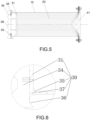
Fig. 5 illustrates a deformation structure diagram of a guiding cylinder and an energy-absorbing material of an optional energy-absorbing anti-creeper in a collision process according to an embodiment of the present disclosure; and -
Fig. 6 illustrates an enlarged structure diagram of a part A of the energy-absorbing anti-creeper inFig. 2 . - The drawings include the following reference signs:
10, guiding cylinder; 20, energy-absorbing material; 30, collision mechanism; 31, pressing plate; 32, shear pin; 33, annular flange; 34, collision plate; 35, front cutter; 36, guiding groove; 37, preset defect groove; 38, anti-creeping tooth; 40, discharging mechanism; 41, guiding cone; 42, guiding ring; 43, rear cutter; and 44, extrusion groove. - It is to be noted that in the case of no conflict, the features in the embodiments and the embodiments in the present application may be combined with each other. The present disclosure is described below with reference to the drawings and in conjunction with the embodiments in detail.
- As shown in
Fig. 1 and Fig. 2 , an energy-absorbing anti-creeper according to an embodiment of the present disclosure includes: a guidingcylinder 10, an energy-absorbingmaterial 20; acollision mechanism 30; and adischarging mechanism 40 for discharging the energy-absorbingmaterial 20 being arranged at the first end of the guidingcylinder 10. A first end of the guidingcylinder 10 is configured to be in assembly connection with a train. The energy-absorbingmaterial 20 is filled in the guidingcylinder 10. Thecollision mechanism 30 is arranged at a second end of the guidingcylinder 10. The first end of the guidingcylinder 10 and the second end of the guidingcylinder 10 are two opposite ends of the guidingcylinder 10. The energy-absorbingmaterial 20 is extruded to deform when a collision occurs between thecollision mechanism 30 and a collision object and then is discharged by thedischarging mechanism 40 so as to buffer an collision energy of the collision object. - An energy-absorbing anti-creeper applying the technical solution of the present disclosure includes a guiding
cylinder 10, an energy-absorbingmaterial 20 and acollision mechanism 30. A first end of the guidingcylinder 10 is configured to be in assembly connection with a train. The energy-absorbingmaterial 20 is filled in the guidingcylinder 10. Thecollision mechanism 30 is arranged at a second end of the guidingcylinder 10. The first end of the guidingcylinder 10 and the second end of the guidingcylinder 10 are two opposite ends of the guidingcylinder 10. A dischargingmechanism 40 for discharging the energy-absorbingmaterial 20 is arranged at the first end of the guidingcylinder 10. The energy-absorbingmaterial 20 is extruded to deform when a collision occurs between thecollision mechanism 30 and a collision object and then is discharged by the dischargingmechanism 40 so as to buffer the collision energy of the collision object. Thus, the energy-absorbingmaterial 20 in the energy-absorbing anti-creeper can be discharged from the dischargingmechanism 40 in the process of being extruded when a train is collided, thereby effectively increasing energy-absorbing efficiency, and solving the problem in the related technology of low energy-absorbing efficiency of an energy-absorbing anti-creeper. - In an exemplary embodiment, the first end of the guiding
cylinder 10 is provided with a mounting seat connected to the train, and the energy-absorbing anti-creeper is in assembly connection with the train by the mounting seat. The energy-absorbingmaterial 20 is a material such as honeycomb aluminum, foamed aluminum, or glass fiber reinforced plastic. As shown inFig. 2 to Fig. 4 , the guidingcylinder 10 is cylindrical. The dischargingmechanism 40 includes: a guidingcone 41. The guidingcone 41 covers an opening of the first end of the guidingcylinder 10. An end face of the guidingcone 41 is provided with a flange portion coupled to the guidingcylinder 10. Correspondingly, the energy-absorbing anti-creeper includes: a connecting flange, coupled to the guidingcone 41 and disposed on the first end of the guidingcylinder 10; and a guidingring 42, coupled to the connecting flange. The flange portion on the guidingcone 41 is coupled to the connecting flange on the guidingcylinder 10 by a bolt. The guidingring 42 is annular and adapted to a diameter of the guidingcylinder 10. The guidingring 42 extends along a circumferential direction of the guidingcylinder 10. A central portion of an inner end face of the guidingcone 41 convexly extends toward the inside of the guidingcylinder 10. After the guidingcone 41 is mounted on the guidingcylinder 10, the passage for discharging the energy-absorbingmaterial 20 is formed between the guidingring 42 and an inner wall surface of the guidingcone 41. The energy-absorbingmaterial 20 in the guidingcylinder 10 is extruded through the gap between the guidingring 42 and the inner wall surface of the guidingcone 41 when being extruded to achieve the effect of enhancing the buffer force. - Since the gap between the guiding
ring 42 and the guidingcone 41 is narrower, the energy-absorbingmaterial 20 is rapidly extruded in the event of a collision, which easily causes a dead zone of the energy-absorbingmaterial 20, that is, the energy-absorbingmaterial 20 cannot be further compressed after being compressed to a certain extent. Therefore, in order to enable the energy-absorbingmaterial 20 to be smoothly discharged from the gap between the guidingring 42 and the guidingcone 41 and to avoid a working dead zone of the energy-absorbingmaterial 20, further, as shown inFig. 3 , the dischargingmechanism 40 also includes: a plurality ofrear cutters 43, the plurality ofrear cutters 43 being spaced apart on the guidingring 42 along a circumferential direction of the guidingring 42. Anextrusion groove 44 is formed between two adjacentrear cutters 43 in the plurality ofrear cutters 43, and the energy-absorbingmaterial 20 is cut into a plurality of pieces by each of the plurality ofrear cutters 43 in a process of being extruded by thecollision mechanism 30 and discharged from a gap between thecorresponding extrusion groove 44 and the inner wall surface of the guidingcone 41. Through the plurality ofrear cutters 43, the energy-absorbingmaterial 20 of which the density is rapidly increased after being extruded can be cut into a plurality of small pieces, thereby facilitating the discharge of the energy-absorbingmaterial 20, reducing the range of the energy-absorbing dead zone of the energy-absorbingmaterial 20, and improving the buffer energy-absorbing capacity. - As shown in
Fig. 2 , thecollision mechanism 30 includes apressing plate 31 and acollision plate 34. Both thepressing plate 31 and thecollision plate 34 are arranged at the second end of the guidingcylinder 10. Thepressing plate 31 is arranged inside a cylinder body and abutted against one end of the energy-absorbingmaterial 20 for extruding the energy-absorbingmaterial 20 when colliding with the collision object. Thepressing plate 31 is coupled to an inner wall of the guidingcylinder 10 by ashear pin 32. An end face, facing the guidingcylinder 10, of thecollision plate 34, is connected to thepressing plate 31, and an end face, facing away from the guidingcylinder 10, of thecollision plate 34, is provided withanti-creeping teeth 38 for contacting the collision object. In an exemplary embodiment, an annular connecting portion is arranged between thecollision plate 34 and thepressing plate 31. Thecollision plate 34 is connected to thepressing plate 31 by the annular connection portion and integrated into one body. There are a plurality ofanti-creeping teeth 38 on thecollision plate 34. The plurality ofanti-creeping teeth 38 are spaced apart on a collision surface of thecollision plate 34 along a transverse direction of thecollision plate 34. - When the train collides with the collision object, as shown in
Fig. 5 , theanti-creeping teeth 38 directly collide with the collision object. Under an action of a large impact force, the energy-absorbingmaterial 20 in the inside of the guidingcylinder 10 is extruded by thecollision plate 34 and thepressing plate 31. Under the pushing action of thecollision plate 34, when an interface force reaches a value, theshear pin 32 for connecting thepressing plate 31 is sheared so that thepressing plate 31 applies an impact force to the energy-absorbingmaterial 20. At the same time of compressing the energy-absorbingmaterial 20, the energy-absorbingmaterial 20 near one end of the dischargingmechanism 40 is extruded through the gap between the guidingring 42 and the inner wall surface of the guidingcone 41. Thus, by the deformation of the energy-absorbingmaterial 20 and the extrusion discharge of the energy-absorbingmaterial 20, the impact force of the collision is buffered and energy-absorbed. The guidingcone 41 guides the energy-absorbingmaterial 20 in the process of discharging the energy-absorbingmaterial 20 through the gap between the guidingring 42 and the inner wall surface of the guidingcone 41. The energy-absorbing material is guided to therear cutters 43 and theextrusion groove 44. - In order to keep the movement of the
pressing plate 31 stable during the pressing process of the energy-absorbingmaterial 20 by thepressing plate 31, further, as shown inFig. 2 , the energy-absorbing anti-creeper includes anannular flange 33 abutting against the inner wall of the guidingcylinder 10, wherein theannular flange 33 is arranged along a circumferential direction of thepressing plate 31. Theannular flange 33 extends for a certain length along an axial direction of the guidingcylinder 10. Thepressing plate 31 has a thickness by providing theannular flange 33 on thepressing plate 31, thereby increasing the contact area of thepressing plate 31 with the inner wall of the guidingcylinder 10 to ensure that thepressing plate 31 can stably extrude the energy-absorbingmaterial 20 under the action of a large impact force. During the collision, a contact portion of thepressing plate 31 and the guidingcylinder 10 is not deformed, and achieves the function of vertical anti-creeping together with theanti-creeping teeth 38. - In order to further enhance the buffer force, as shown in
Fig. 2 andFig. 6 , thecollision mechanism 30 further includes: a plurality offront cutters 35. The plurality offront cutters 35 are arranged on the end face of thecollision plate 34 facing the guidingcylinder 10. The plurality offront cutters 35 are spaced apart along a circumferential direction of an inner wall of the guidingcylinder 10. As shown inFig. 5 , when thecollision mechanism 30 is collided by the collision object, the plurality offront cutters 35 cut a part of the inner wall of the guidingcylinder 10 along a movement direction of thecollision plate 34. A portion of the cut part is curled toward the inside of the guidingcylinder 10, and the remaining portion of the cut part is curled toward the outside of the guidingcylinder 10 under the action of a rear end wall of thecollision plate 34, thereby increasing the pushing resistance. By cutting, the effective energy-absorbing stroke of the entire energy-absorbing anti-creeper is increased, thereby improving the buffer energy-absorbing effect. - In order to facilitate better bending and curling of the cylinder wall of the guiding
cylinder 10 which is curled toward the outside of the guidingcylinder 10 after being cut by thefront cutters 35 so as to further enhance the energy-absorbing effect, In an exemplary embodiment, as shown inFig. 2 andFig. 6 , thecollision mechanism 30 further includes a guidinggroove 36. The guidinggroove 36 is provided on the end face of thecollision plate 34 facing the guidingcylinder 10. The guidinggroove 36 surrounds a circumferential direction of the guidingcylinder 10. Each of thefront cutters 35 is adjacent to the inner edge of the guidinggroove 36. The groove wall of the guidinggroove 36 is an arc surface. The bent part of the end wall of the guidingcylinder 10 curled toward the outside of the guidingcylinder 10 when being cut and extruded is curled by the arc surface of the guidinggroove 36, thereby further improving the energy-absorbing effect. - In order to make blades of the
front cutters 35 smoothly cut the cylinder wall of the guidingcylinder 10 at a beginning of the collision, In an exemplary embodiment, a position of the guidingcylinder 10 corresponding to each of thefront cutters 35 is provided with apreset defect groove 37, thepreset defect groove 37 extending along the axial direction of the guidingcylinder 10. At a moment when the collision is started, the blades of the front cutters start cutting the cylinder wall of the guidingcylinder 10 from thepreset defect groove 37 to prevent a hard collision between the cutters and the cylinder wall of the guidingcylinder 10. - According to another embodiment of the present disclosure, a train vehicle is provided, which includes an energy-absorbing anti-creeper. The energy-absorbing anti-creeper is the energy-absorbing anti-creeper in the above embodiment. A rear end of the energy-absorbing anti-creeper is provided with a mounting seat. The mounting seat is provided with a mounting port connected to the train vehicle. The energy-absorbing anti-creeper is in assembly connection with the train by the mounting seat. In an exemplary embodiment, a guiding
cone 41 at a rear end of the energy-absorbing anti-creeper is integrated on the mounting seat. According to the train vehicle applying the energy-absorbing anti-creeper of the above embodiment, the energy-absorbingmaterial 20 in the energy-absorbing anti-creeper can be discharged from the dischargingmechanism 40 in the process of being extruded when a train is collided, thereby effectively increasing energy-absorbing efficiency, and solving the problem in the related technology of low energy-absorbing efficiency of an energy-absorbing anti-creeper. - In a specific implementation, there are a plurality of energy-absorbing anti-creepers on each train. The plurality of energy-absorbing anti-creepers are arranged at front and rear ends of the train vehicle respectively. When two trains collide, the energy-absorbing anti-creeper at a front end of one train collides with the energy-absorbing anti-creeper at a rear end of the other train and buffers the impact force. During the collision,
anti-creeping teeth 38 at front ends of the two energy-absorbing anti-creepers are in contact with each other and are extruded. A good vertical anti-creeping function is always kept. Collision by theanti-creeping teeth 38 can effectively prevent the train from derailing.
Claims (11)
- An energy-absorbing anti-creeper, comprising:a guiding cylinder (10), a first end of the guiding cylinder (10) being configured to be in assembly connection with a train;an energy-absorbing material (20), filled in the guiding cylinder (10);a collision mechanism (30), arranged at a second end of the guiding cylinder (10); anda discharging mechanism (40) for discharging the energy-absorbing material (20) being arranged at the first end of the guiding cylinder (10);wherein the first end of the guiding cylinder (10) and the second end of the guiding cylinder (10) are two opposite ends of the guiding cylinder (10), and the energy-absorbing material (20) is extruded to deform when a collision occurs between the collision mechanism (30) and a collision object and then is discharged by the discharging mechanism (40) so as to buffer an collision energy of the collision object;wherein the collision mechanism (30) comprises:a pressing plate (31), arranged inside a cylinder body of the second end of the guiding cylinder (10) and abutted against the energy-absorbing material (20), wherein the pressing plate (31) is configured to extrude the energy-absorbing material (20) when colliding with the collision object.wherein the collision mechanism (30) further comprises:a collision plate (34), arranged at the second end of the guiding cylinder (10), an end face, facing the guiding cylinder (10), of the collision plate (34), is coupled to the pressing plate (31), and an end face, facing away from the guiding cylinder (10), of the collision plate (34), is provided with anti-creeping teeth (38) for contacting the collision object.wherein the energy-absorbing anti-creeper is characterized by the fact that the collision mechanism (30) further comprises:
a plurality of front cutters (35), arranged on the end face of the collision plate (34) facing the guiding cylinder (10), the plurality of front cutters (35) being spaced apart along a circumferential direction of an inner wall of the guiding cylinder (10) to cut the guiding cylinder (10) along a movement direction of the collision plate (34) when the collision mechanism (30) is collided by the collision object. - The energy-absorbing anti-creeper according to claim 1, wherein the discharging mechanism (40) comprises:a guiding cone (41), covering an opening of the first end of the guiding cylinder (10),wherein a gap is provided between the guiding cone (41) and a cylinder edge of the first end of the guiding cylinder (10), the gap forming a passage for discharging the energy-absorbing material (20).
- The energy-absorbing anti-creeper according to claim 2, wherein the guiding cylinder (10) is of cylindrical, and an end face of the guiding cone (41) is provided with a flange portion coupled to the guiding cylinder (10).
- The energy-absorbing anti-creeper according to claim 2, wherein the energy-absorbing anti-creeper comprises:a connecting flange, coupled to the guiding cone (41) and disposed on the first end of the guiding cylinder (10); anda guiding ring (42), coupled to the connecting flange wherein the guiding ring (42) extends along a circumferential direction of the guiding cylinder (10), and the passage for discharging the energy-absorbing material (20) is formed between the guiding ring (42) and an inner wall surface of the guiding cone (41).
- The energy-absorbing anti-creeper according to claim 4, wherein the guiding ring (42) is of annular, and the discharging mechanism (40) further comprises:a plurality of rear cutters (43), the plurality of rear cutters (43) being spaced apart on the guiding ring (42) along a circumferential direction of the guiding ring (42),wherein an extrusion groove (44) is formed between two adjacent rear cutters (43) in the plurality of rear cutters (43), and the energy-absorbing material (20) is cut into a plurality of pieces by each of the plurality of rear cutters (43) in a process of being extruded by the collision mechanism (30) and discharged from a gap between the extrusion groove (44) and the inner wall surface of the guiding cone (41).
- The energy-absorbing anti-creeper according to claim 1, wherein the pressing plate (31) is coupled to an inner wall of the guiding cylinder (10) by a shear pin (32).
- The energy-absorbing anti-creeper according to claim 1, wherein the energy-absorbing anti-creeper comprises an annular flange (33) abutting against the inner wall of the guiding cylinder (10), wherein the annular flange (33) is arranged along a circumferential direction of the pressing plate (31), and the annular flange (33) extends along an axial direction of the guiding cylinder (10).
- The energy-absorbing anti-creeper according to claim 1, wherein the collision mechanism (30) further comprises:
a guiding groove (36), provided on the end face of the collision plate (34) facing the guiding cylinder (10), the guiding groove (36) surrounding a circumferential direction of the guiding cylinder (10) such that an end wall of the guiding cylinder (10) is curled along the guiding groove (36) when being cut and extruded. - The energy-absorbing anti-creeper according to claim 1 wherein a position of the guiding cylinder (10) corresponding to each of the plurality of front cutters (35) is provided with a preset defect groove (37), the preset defect groove (37) extending along the axial direction of the guiding cylinder (10).
- A train vehicle, comprising an energy-absorbing anti-creeper, wherein the energy-absorbing anti-creeper is the energy-absorbing anti-creeper according to any one of claims 1 to 9.
- The train vehicle according to claim 10, wherein there are a plurality of energy-absorbing anti-creepers, the plurality of energy-absorbing anti-creepers are arranged at front and rear ends of the train vehicle respectively.
Applications Claiming Priority (2)
| Application Number | Priority Date | Filing Date | Title |
|---|---|---|---|
| CN201710556167.XA CN107512281B (en) | 2017-07-11 | 2017-07-11 | Energy-absorbing anti-climbing device and train vehicle having the same |
| PCT/CN2018/083852 WO2019011029A1 (en) | 2017-07-11 | 2018-04-20 | Energy-absorbing anti-creeper and train vehicle having same |
Publications (3)
| Publication Number | Publication Date |
|---|---|
| EP3611071A1 EP3611071A1 (en) | 2020-02-19 |
| EP3611071A4 EP3611071A4 (en) | 2020-12-16 |
| EP3611071B1 true EP3611071B1 (en) | 2023-02-15 |
Family
ID=60722367
Family Applications (1)
| Application Number | Title | Priority Date | Filing Date |
|---|---|---|---|
| EP18832693.8A Active EP3611071B1 (en) | 2017-07-11 | 2018-04-20 | Energy-absorbing anti-creeper and train vehicle with energy-absorbing anti-creeper |
Country Status (8)
| Country | Link |
|---|---|
| US (1) | US11447161B2 (en) |
| EP (1) | EP3611071B1 (en) |
| CN (1) | CN107512281B (en) |
| CA (1) | CA3063239C (en) |
| ES (1) | ES2941542T3 (en) |
| RU (1) | RU2730292C2 (en) |
| SG (1) | SG11201912522YA (en) |
| WO (1) | WO2019011029A1 (en) |
Families Citing this family (15)
| Publication number | Priority date | Publication date | Assignee | Title |
|---|---|---|---|---|
| CN107512281B (en) | 2017-07-11 | 2019-03-22 | 中车青岛四方机车车辆股份有限公司 | Energy-absorbing anti-climbing device and train vehicle having the same |
| CN108248534A (en) * | 2018-01-19 | 2018-07-06 | 青岛四方庞巴迪铁路运输设备有限公司 | Energy-absorbing device of vehicle body and its method |
| CN108674635B (en) * | 2018-05-07 | 2019-06-28 | 中国飞机强度研究所 | A kind of undercarriage pendant hits energy absorption device |
| CN109291951B (en) * | 2018-10-22 | 2019-09-27 | 中车青岛四方车辆研究所有限公司 | A kind of close-coupled anti-climbing energy-absorbing device |
| AT521684B1 (en) * | 2018-11-26 | 2020-04-15 | Siemens Mobility Austria Gmbh | Climbing protection device for a rail vehicle |
| CN110341744B (en) * | 2019-07-11 | 2024-06-07 | 深圳市乾行达科技有限公司 | Buffering and energy absorbing device |
| CN112389487B (en) * | 2019-08-14 | 2022-05-17 | 中车唐山机车车辆有限公司 | Energy absorption device and railway vehicle |
| CN110588702B (en) * | 2019-09-18 | 2024-06-11 | 西南交通大学 | Induced crushing energy absorber of railway vehicle |
| CN111469789B (en) * | 2020-04-30 | 2023-06-23 | 中国飞机强度研究所 | Combined collision energy absorption structure and application method thereof |
| CN111845830B (en) * | 2020-08-25 | 2024-06-04 | 中车青岛四方车辆研究所有限公司 | Train passive collision energy absorbing device and rail train |
| CN113830129B (en) * | 2021-11-10 | 2024-04-26 | 中车南京浦镇车辆有限公司 | Planing type anti-creeper for railway vehicle |
| CN114604285B (en) * | 2022-03-28 | 2023-07-14 | 深圳市乾行达科技有限公司 | Anti-creeping energy-absorbing device |
| CN115467272B (en) * | 2022-10-20 | 2024-05-31 | 山东高速股份有限公司 | Extrusion opening energy absorption method and anti-collision pad structure |
| CN115614415B (en) * | 2022-10-21 | 2025-10-14 | 中南林业科技大学 | A combined cutting energy absorption device |
| CN116161069B (en) * | 2023-02-10 | 2026-03-17 | 河南科技大学 | A rotary cutting anti-climb energy absorption device |
Family Cites Families (20)
| Publication number | Priority date | Publication date | Assignee | Title |
|---|---|---|---|---|
| US2997325A (en) | 1959-09-15 | 1961-08-22 | Gerald H Peterson | Kinetic energy absorber |
| RU2197401C2 (en) * | 2000-12-21 | 2003-01-27 | Открытое акционерное общество "Авиаагрегат" | Draft gear |
| CN2716087Y (en) * | 2004-10-26 | 2005-08-10 | 何克鉴 | Pressure shearing energy discharging type automobile collision protection device |
| JP2007210441A (en) * | 2006-02-09 | 2007-08-23 | Hitachi Ltd | Energy absorbing material and transportation equipment provided with energy absorbing material |
| KR100916598B1 (en) * | 2007-12-06 | 2009-09-11 | 한국철도기술연구원 | Tearing Tube Buffer for Railway Vehicles |
| EP2227410A4 (en) * | 2007-12-06 | 2013-03-13 | Korea Railroad Res Inst | TUBULAR BUFFER FOR RAILWAY VEHICLES |
| RU92397U1 (en) * | 2009-06-29 | 2010-03-20 | Валентин Гаврилович Подойников | SHOCK ENERGY DISPOSAL DEVICE FOR RAILWAY VEHICLE |
| KR101125769B1 (en) * | 2009-12-07 | 2012-04-12 | 한국철도기술연구원 | tube-buffer using expanding and tearing progress |
| CN102398558A (en) * | 2010-09-08 | 2012-04-04 | 李书营 | Collision buffering energy absorption device |
| CN103287449A (en) * | 2013-06-20 | 2013-09-11 | 南车南京浦镇车辆有限公司 | Subway train anti-climbing energy absorber |
| ES2807210T3 (en) * | 2014-02-27 | 2021-02-22 | Hitachi Rail S P A | Energy absorption device, in particular for a railway vehicle |
| CN103818402B (en) * | 2014-03-13 | 2016-06-01 | 西南交通大学 | Suction for rail traffic vehicles can be prevented climbing device |
| CN104494629B (en) * | 2014-11-19 | 2017-02-22 | 西南交通大学 | Compression type multistep energy absorption device |
| CN204713095U (en) * | 2015-06-15 | 2015-10-21 | 深圳市乾行达科技有限公司 | A kind of anti-creeper of porous material filling walled metallic structure |
| CN204895482U (en) * | 2015-07-31 | 2015-12-23 | 陈文杰 | A energy -absorbing anti -creep device for track transportation vehicles |
| CN105438212A (en) * | 2015-12-30 | 2016-03-30 | 深圳市乾行达科技有限公司 | Cutting type anti-creeper |
| CN105644579B (en) | 2016-03-01 | 2018-08-28 | 中南大学 | A kind of collision energy-absorbing device used for rail vehicle |
| CN105905056B (en) * | 2016-06-02 | 2018-03-13 | 上海交通大学 | Impact energy absorber based on composite material pipe cutting varus conquassation |
| CN205997888U (en) * | 2016-08-25 | 2017-03-08 | 深圳市乾行达科技有限公司 | A kind of drawer type honeycomb fashion anti-creep energy absorber |
| CN107512281B (en) * | 2017-07-11 | 2019-03-22 | 中车青岛四方机车车辆股份有限公司 | Energy-absorbing anti-climbing device and train vehicle having the same |
-
2017
- 2017-07-11 CN CN201710556167.XA patent/CN107512281B/en active Active
-
2018
- 2018-04-20 RU RU2020100586A patent/RU2730292C2/en active
- 2018-04-20 ES ES18832693T patent/ES2941542T3/en active Active
- 2018-04-20 US US16/624,044 patent/US11447161B2/en active Active
- 2018-04-20 SG SG11201912522YA patent/SG11201912522YA/en unknown
- 2018-04-20 EP EP18832693.8A patent/EP3611071B1/en active Active
- 2018-04-20 CA CA3063239A patent/CA3063239C/en active Active
- 2018-04-20 WO PCT/CN2018/083852 patent/WO2019011029A1/en not_active Ceased
Also Published As
| Publication number | Publication date |
|---|---|
| US11447161B2 (en) | 2022-09-20 |
| ES2941542T3 (en) | 2023-05-23 |
| WO2019011029A1 (en) | 2019-01-17 |
| RU2020100586A (en) | 2020-04-27 |
| CN107512281B (en) | 2019-03-22 |
| RU2020100586A3 (en) | 2020-06-23 |
| EP3611071A1 (en) | 2020-02-19 |
| US20200130715A1 (en) | 2020-04-30 |
| RU2730292C2 (en) | 2020-08-21 |
| CA3063239C (en) | 2022-03-01 |
| SG11201912522YA (en) | 2020-01-30 |
| BR112019027831A2 (en) | 2020-09-01 |
| CA3063239A1 (en) | 2019-12-03 |
| CN107512281A (en) | 2017-12-26 |
| EP3611071A4 (en) | 2020-12-16 |
Similar Documents
| Publication | Publication Date | Title |
|---|---|---|
| EP3611071B1 (en) | Energy-absorbing anti-creeper and train vehicle with energy-absorbing anti-creeper | |
| CN106364520B (en) | A kind of train collision means of defence and system | |
| EP3424794B1 (en) | Collision energy absorption apparatus for rail vehicles | |
| CN105151075B (en) | A kind of energy absorption device and the rail vehicle with the energy absorption device | |
| CN109291951B (en) | A kind of close-coupled anti-climbing energy-absorbing device | |
| CN103818402A (en) | Energy absorbing anti-creep device for track traffic vehicles | |
| CN102612579A (en) | Mechanism for absorbing kinetic energy from frontal impacts of vehicles against vehicle restraining systems, for using on the edges and central reservations of roadways, such as shock absorbers and barrier ends | |
| CN112389487B (en) | Energy absorption device and railway vehicle | |
| CN103863351A (en) | Diameter expanding and cutting composite type energy dissipation device and vehicle | |
| CN111976780B (en) | Central coupler suitable for collision energy management system and locomotive with same | |
| CN115214739A (en) | Energy-absorbing structure and energy-absorbing anti-creep device | |
| CN109515468B (en) | Energy-absorbing anti-creeper of composite railway vehicle | |
| CN117775058A (en) | An anti-climbing energy-absorbing device for high-speed trains | |
| CN103192845B (en) | The anti-bias energy absorption device of a kind of anti-creep | |
| CN217145989U (en) | Expansion and contraction combined type energy-absorbing anti-creeper for railway vehicle | |
| EP3357785B1 (en) | Energy absorption device and rail vehicle having same | |
| US10857959B2 (en) | Controlled axle release mechanism for a truck trailer attenuator | |
| CN221477105U (en) | Anti-climbing energy-absorbing device for high-speed train | |
| CN204309726U (en) | Automobile collapse energy-absorption box | |
| CN111439287B (en) | Anti-climbing energy-absorbing device for train | |
| CN115467272A (en) | Energy absorption method for extrusion port and anti-collision pad structure | |
| CN204309566U (en) | A kind of endergonic structure of arrangements for automotive doors | |
| CN113911162B (en) | Guide frame structure for multi-stage energy absorption of railway vehicle | |
| CN114030500B (en) | Supporting type guide frame structure for multi-stage energy absorption of railway vehicle | |
| BR112019027831B1 (en) | ENERGY-ABSORPTION ANTI-SCIBLING DEVICE AND A RAILWAY VEHICLE WITH AN ENERGY-ABSORPTION ANTI-SCIBLING DEVICE |
Legal Events
| Date | Code | Title | Description |
|---|---|---|---|
| STAA | Information on the status of an ep patent application or granted ep patent |
Free format text: STATUS: THE INTERNATIONAL PUBLICATION HAS BEEN MADE |
|
| PUAI | Public reference made under article 153(3) epc to a published international application that has entered the european phase |
Free format text: ORIGINAL CODE: 0009012 |
|
| STAA | Information on the status of an ep patent application or granted ep patent |
Free format text: STATUS: REQUEST FOR EXAMINATION WAS MADE |
|
| 17P | Request for examination filed |
Effective date: 20191112 |
|
| AK | Designated contracting states |
Kind code of ref document: A1 Designated state(s): AL AT BE BG CH CY CZ DE DK EE ES FI FR GB GR HR HU IE IS IT LI LT LU LV MC MK MT NL NO PL PT RO RS SE SI SK SM TR |
|
| AX | Request for extension of the european patent |
Extension state: BA ME |
|
| DAV | Request for validation of the european patent (deleted) | ||
| DAX | Request for extension of the european patent (deleted) | ||
| A4 | Supplementary search report drawn up and despatched |
Effective date: 20201116 |
|
| RIC1 | Information provided on ipc code assigned before grant |
Ipc: B61G 11/16 20060101AFI20201110BHEP Ipc: B61F 19/04 20060101ALI20201110BHEP |
|
| REG | Reference to a national code |
Ref country code: DE Ref legal event code: R079 Ref document number: 602018046230 Country of ref document: DE Free format text: PREVIOUS MAIN CLASS: B61F0019040000 Ipc: B61G0011160000 |
|
| RIC1 | Information provided on ipc code assigned before grant |
Ipc: B61F 19/04 20060101ALI20220729BHEP Ipc: B61G 11/16 20060101AFI20220729BHEP |
|
| GRAP | Despatch of communication of intention to grant a patent |
Free format text: ORIGINAL CODE: EPIDOSNIGR1 |
|
| STAA | Information on the status of an ep patent application or granted ep patent |
Free format text: STATUS: GRANT OF PATENT IS INTENDED |
|
| INTG | Intention to grant announced |
Effective date: 20220916 |
|
| RIN1 | Information on inventor provided before grant (corrected) |
Inventor name: LI, LUXING Inventor name: ZHAO, SHIZHONG Inventor name: TIAN, HONGLEI Inventor name: TIAN, AIQIN Inventor name: ZHANG, YONGGUI Inventor name: DING, SANSAN |
|
| GRAS | Grant fee paid |
Free format text: ORIGINAL CODE: EPIDOSNIGR3 |
|
| GRAA | (expected) grant |
Free format text: ORIGINAL CODE: 0009210 |
|
| STAA | Information on the status of an ep patent application or granted ep patent |
Free format text: STATUS: THE PATENT HAS BEEN GRANTED |
|
| AK | Designated contracting states |
Kind code of ref document: B1 Designated state(s): AL AT BE BG CH CY CZ DE DK EE ES FI FR GB GR HR HU IE IS IT LI LT LU LV MC MK MT NL NO PL PT RO RS SE SI SK SM TR |
|
| REG | Reference to a national code |
Ref country code: CH Ref legal event code: EP Ref country code: GB Ref legal event code: FG4D |
|
| REG | Reference to a national code |
Ref country code: RO Ref legal event code: EPE |
|
| REG | Reference to a national code |
Ref country code: DE Ref legal event code: R096 Ref document number: 602018046230 Country of ref document: DE |
|
| REG | Reference to a national code |
Ref country code: AT Ref legal event code: REF Ref document number: 1548110 Country of ref document: AT Kind code of ref document: T Effective date: 20230315 Ref country code: IE Ref legal event code: FG4D |
|
| REG | Reference to a national code |
Ref country code: ES Ref legal event code: FG2A Ref document number: 2941542 Country of ref document: ES Kind code of ref document: T3 Effective date: 20230523 |
|
| REG | Reference to a national code |
Ref country code: LT Ref legal event code: MG9D |
|
| REG | Reference to a national code |
Ref country code: NL Ref legal event code: MP Effective date: 20230215 |
|
| REG | Reference to a national code |
Ref country code: AT Ref legal event code: MK05 Ref document number: 1548110 Country of ref document: AT Kind code of ref document: T Effective date: 20230215 |
|
| PG25 | Lapsed in a contracting state [announced via postgrant information from national office to epo] |
Ref country code: RS Free format text: LAPSE BECAUSE OF FAILURE TO SUBMIT A TRANSLATION OF THE DESCRIPTION OR TO PAY THE FEE WITHIN THE PRESCRIBED TIME-LIMIT Effective date: 20230215 Ref country code: PT Free format text: LAPSE BECAUSE OF FAILURE TO SUBMIT A TRANSLATION OF THE DESCRIPTION OR TO PAY THE FEE WITHIN THE PRESCRIBED TIME-LIMIT Effective date: 20230615 Ref country code: NO Free format text: LAPSE BECAUSE OF FAILURE TO SUBMIT A TRANSLATION OF THE DESCRIPTION OR TO PAY THE FEE WITHIN THE PRESCRIBED TIME-LIMIT Effective date: 20230515 Ref country code: NL Free format text: LAPSE BECAUSE OF FAILURE TO SUBMIT A TRANSLATION OF THE DESCRIPTION OR TO PAY THE FEE WITHIN THE PRESCRIBED TIME-LIMIT Effective date: 20230215 Ref country code: LV Free format text: LAPSE BECAUSE OF FAILURE TO SUBMIT A TRANSLATION OF THE DESCRIPTION OR TO PAY THE FEE WITHIN THE PRESCRIBED TIME-LIMIT Effective date: 20230215 Ref country code: LT Free format text: LAPSE BECAUSE OF FAILURE TO SUBMIT A TRANSLATION OF THE DESCRIPTION OR TO PAY THE FEE WITHIN THE PRESCRIBED TIME-LIMIT Effective date: 20230215 Ref country code: HR Free format text: LAPSE BECAUSE OF FAILURE TO SUBMIT A TRANSLATION OF THE DESCRIPTION OR TO PAY THE FEE WITHIN THE PRESCRIBED TIME-LIMIT Effective date: 20230215 Ref country code: AT Free format text: LAPSE BECAUSE OF FAILURE TO SUBMIT A TRANSLATION OF THE DESCRIPTION OR TO PAY THE FEE WITHIN THE PRESCRIBED TIME-LIMIT Effective date: 20230215 |
|
| PG25 | Lapsed in a contracting state [announced via postgrant information from national office to epo] |
Ref country code: SE Free format text: LAPSE BECAUSE OF FAILURE TO SUBMIT A TRANSLATION OF THE DESCRIPTION OR TO PAY THE FEE WITHIN THE PRESCRIBED TIME-LIMIT Effective date: 20230215 Ref country code: PL Free format text: LAPSE BECAUSE OF FAILURE TO SUBMIT A TRANSLATION OF THE DESCRIPTION OR TO PAY THE FEE WITHIN THE PRESCRIBED TIME-LIMIT Effective date: 20230215 Ref country code: IS Free format text: LAPSE BECAUSE OF FAILURE TO SUBMIT A TRANSLATION OF THE DESCRIPTION OR TO PAY THE FEE WITHIN THE PRESCRIBED TIME-LIMIT Effective date: 20230615 Ref country code: GR Free format text: LAPSE BECAUSE OF FAILURE TO SUBMIT A TRANSLATION OF THE DESCRIPTION OR TO PAY THE FEE WITHIN THE PRESCRIBED TIME-LIMIT Effective date: 20230516 Ref country code: FI Free format text: LAPSE BECAUSE OF FAILURE TO SUBMIT A TRANSLATION OF THE DESCRIPTION OR TO PAY THE FEE WITHIN THE PRESCRIBED TIME-LIMIT Effective date: 20230215 |
|
| PG25 | Lapsed in a contracting state [announced via postgrant information from national office to epo] |
Ref country code: SM Free format text: LAPSE BECAUSE OF FAILURE TO SUBMIT A TRANSLATION OF THE DESCRIPTION OR TO PAY THE FEE WITHIN THE PRESCRIBED TIME-LIMIT Effective date: 20230215 Ref country code: EE Free format text: LAPSE BECAUSE OF FAILURE TO SUBMIT A TRANSLATION OF THE DESCRIPTION OR TO PAY THE FEE WITHIN THE PRESCRIBED TIME-LIMIT Effective date: 20230215 Ref country code: DK Free format text: LAPSE BECAUSE OF FAILURE TO SUBMIT A TRANSLATION OF THE DESCRIPTION OR TO PAY THE FEE WITHIN THE PRESCRIBED TIME-LIMIT Effective date: 20230215 Ref country code: CZ Free format text: LAPSE BECAUSE OF FAILURE TO SUBMIT A TRANSLATION OF THE DESCRIPTION OR TO PAY THE FEE WITHIN THE PRESCRIBED TIME-LIMIT Effective date: 20230215 |
|
| REG | Reference to a national code |
Ref country code: DE Ref legal event code: R097 Ref document number: 602018046230 Country of ref document: DE |
|
| PG25 | Lapsed in a contracting state [announced via postgrant information from national office to epo] |
Ref country code: SK Free format text: LAPSE BECAUSE OF FAILURE TO SUBMIT A TRANSLATION OF THE DESCRIPTION OR TO PAY THE FEE WITHIN THE PRESCRIBED TIME-LIMIT Effective date: 20230215 |
|
| REG | Reference to a national code |
Ref country code: CH Ref legal event code: PL |
|
| PLBE | No opposition filed within time limit |
Free format text: ORIGINAL CODE: 0009261 |
|
| STAA | Information on the status of an ep patent application or granted ep patent |
Free format text: STATUS: NO OPPOSITION FILED WITHIN TIME LIMIT |
|
| PG25 | Lapsed in a contracting state [announced via postgrant information from national office to epo] |
Ref country code: LU Free format text: LAPSE BECAUSE OF NON-PAYMENT OF DUE FEES Effective date: 20230420 |
|
| REG | Reference to a national code |
Ref country code: BE Ref legal event code: MM Effective date: 20230430 |
|
| PG25 | Lapsed in a contracting state [announced via postgrant information from national office to epo] |
Ref country code: MC Free format text: LAPSE BECAUSE OF FAILURE TO SUBMIT A TRANSLATION OF THE DESCRIPTION OR TO PAY THE FEE WITHIN THE PRESCRIBED TIME-LIMIT Effective date: 20230215 |
|
| 26N | No opposition filed |
Effective date: 20231116 |
|
| GBPC | Gb: european patent ceased through non-payment of renewal fee |
Effective date: 20230515 |
|
| PG25 | Lapsed in a contracting state [announced via postgrant information from national office to epo] |
Ref country code: SI Free format text: LAPSE BECAUSE OF FAILURE TO SUBMIT A TRANSLATION OF THE DESCRIPTION OR TO PAY THE FEE WITHIN THE PRESCRIBED TIME-LIMIT Effective date: 20230215 Ref country code: MC Free format text: LAPSE BECAUSE OF FAILURE TO SUBMIT A TRANSLATION OF THE DESCRIPTION OR TO PAY THE FEE WITHIN THE PRESCRIBED TIME-LIMIT Effective date: 20230215 Ref country code: LI Free format text: LAPSE BECAUSE OF NON-PAYMENT OF DUE FEES Effective date: 20230430 Ref country code: CH Free format text: LAPSE BECAUSE OF NON-PAYMENT OF DUE FEES Effective date: 20230430 |
|
| REG | Reference to a national code |
Ref country code: IE Ref legal event code: MM4A |
|
| PG25 | Lapsed in a contracting state [announced via postgrant information from national office to epo] |
Ref country code: BE Free format text: LAPSE BECAUSE OF NON-PAYMENT OF DUE FEES Effective date: 20230430 |
|
| PG25 | Lapsed in a contracting state [announced via postgrant information from national office to epo] |
Ref country code: IE Free format text: LAPSE BECAUSE OF NON-PAYMENT OF DUE FEES Effective date: 20230420 |
|
| PG25 | Lapsed in a contracting state [announced via postgrant information from national office to epo] |
Ref country code: IE Free format text: LAPSE BECAUSE OF NON-PAYMENT OF DUE FEES Effective date: 20230420 Ref country code: GB Free format text: LAPSE BECAUSE OF NON-PAYMENT OF DUE FEES Effective date: 20230515 |
|
| PG25 | Lapsed in a contracting state [announced via postgrant information from national office to epo] |
Ref country code: IT Free format text: LAPSE BECAUSE OF FAILURE TO SUBMIT A TRANSLATION OF THE DESCRIPTION OR TO PAY THE FEE WITHIN THE PRESCRIBED TIME-LIMIT Effective date: 20230215 |
|
| PG25 | Lapsed in a contracting state [announced via postgrant information from national office to epo] |
Ref country code: BG Free format text: LAPSE BECAUSE OF FAILURE TO SUBMIT A TRANSLATION OF THE DESCRIPTION OR TO PAY THE FEE WITHIN THE PRESCRIBED TIME-LIMIT Effective date: 20230215 |
|
| PG25 | Lapsed in a contracting state [announced via postgrant information from national office to epo] |
Ref country code: BG Free format text: LAPSE BECAUSE OF FAILURE TO SUBMIT A TRANSLATION OF THE DESCRIPTION OR TO PAY THE FEE WITHIN THE PRESCRIBED TIME-LIMIT Effective date: 20230215 |
|
| PGFP | Annual fee paid to national office [announced via postgrant information from national office to epo] |
Ref country code: DE Payment date: 20250417 Year of fee payment: 8 |
|
| PGFP | Annual fee paid to national office [announced via postgrant information from national office to epo] |
Ref country code: ES Payment date: 20250519 Year of fee payment: 8 |
|
| PG25 | Lapsed in a contracting state [announced via postgrant information from national office to epo] |
Ref country code: CY Free format text: LAPSE BECAUSE OF FAILURE TO SUBMIT A TRANSLATION OF THE DESCRIPTION OR TO PAY THE FEE WITHIN THE PRESCRIBED TIME-LIMIT; INVALID AB INITIO Effective date: 20180420 |
|
| PG25 | Lapsed in a contracting state [announced via postgrant information from national office to epo] |
Ref country code: HU Free format text: LAPSE BECAUSE OF FAILURE TO SUBMIT A TRANSLATION OF THE DESCRIPTION OR TO PAY THE FEE WITHIN THE PRESCRIBED TIME-LIMIT; INVALID AB INITIO Effective date: 20180420 |
|
| PG25 | Lapsed in a contracting state [announced via postgrant information from national office to epo] |
Ref country code: TR Free format text: LAPSE BECAUSE OF FAILURE TO SUBMIT A TRANSLATION OF THE DESCRIPTION OR TO PAY THE FEE WITHIN THE PRESCRIBED TIME-LIMIT Effective date: 20230215 |
|
| PGFP | Annual fee paid to national office [announced via postgrant information from national office to epo] |
Ref country code: RO Payment date: 20260326 Year of fee payment: 9 |
|
| PGFP | Annual fee paid to national office [announced via postgrant information from national office to epo] |
Ref country code: FR Payment date: 20260317 Year of fee payment: 9 |