EP3611059A1 - Parking assist sensor holder - Google Patents
Parking assist sensor holder Download PDFInfo
- Publication number
- EP3611059A1 EP3611059A1 EP19192120.4A EP19192120A EP3611059A1 EP 3611059 A1 EP3611059 A1 EP 3611059A1 EP 19192120 A EP19192120 A EP 19192120A EP 3611059 A1 EP3611059 A1 EP 3611059A1
- Authority
- EP
- European Patent Office
- Prior art keywords
- pas
- holder
- body portion
- mounting component
- mounting
- Prior art date
- Legal status (The legal status is an assumption and is not a legal conclusion. Google has not performed a legal analysis and makes no representation as to the accuracy of the status listed.)
- Granted
Links
Images




Classifications
-
- B—PERFORMING OPERATIONS; TRANSPORTING
- B60—VEHICLES IN GENERAL
- B60R—VEHICLES, VEHICLE FITTINGS, OR VEHICLE PARTS, NOT OTHERWISE PROVIDED FOR
- B60R19/00—Wheel guards; Radiator guards, e.g. grilles; Obstruction removers; Fittings damping bouncing force in collisions
- B60R19/02—Bumpers, i.e. impact receiving or absorbing members for protecting vehicles or fending off blows from other vehicles or objects
- B60R19/48—Bumpers, i.e. impact receiving or absorbing members for protecting vehicles or fending off blows from other vehicles or objects combined with, or convertible into, other devices or objects, e.g. bumpers combined with road brushes, bumpers convertible into beds
- B60R19/483—Bumpers, i.e. impact receiving or absorbing members for protecting vehicles or fending off blows from other vehicles or objects combined with, or convertible into, other devices or objects, e.g. bumpers combined with road brushes, bumpers convertible into beds with obstacle sensors of electric or electronic type
-
- F—MECHANICAL ENGINEERING; LIGHTING; HEATING; WEAPONS; BLASTING
- F16—ENGINEERING ELEMENTS AND UNITS; GENERAL MEASURES FOR PRODUCING AND MAINTAINING EFFECTIVE FUNCTIONING OF MACHINES OR INSTALLATIONS; THERMAL INSULATION IN GENERAL
- F16B—DEVICES FOR FASTENING OR SECURING CONSTRUCTIONAL ELEMENTS OR MACHINE PARTS TOGETHER, e.g. NAILS, BOLTS, CIRCLIPS, CLAMPS, CLIPS OR WEDGES; JOINTS OR JOINTING
- F16B11/00—Connecting constructional elements or machine parts by sticking or pressing them together, e.g. cold pressure welding
- F16B11/006—Connecting constructional elements or machine parts by sticking or pressing them together, e.g. cold pressure welding by gluing
-
- F—MECHANICAL ENGINEERING; LIGHTING; HEATING; WEAPONS; BLASTING
- F16—ENGINEERING ELEMENTS AND UNITS; GENERAL MEASURES FOR PRODUCING AND MAINTAINING EFFECTIVE FUNCTIONING OF MACHINES OR INSTALLATIONS; THERMAL INSULATION IN GENERAL
- F16B—DEVICES FOR FASTENING OR SECURING CONSTRUCTIONAL ELEMENTS OR MACHINE PARTS TOGETHER, e.g. NAILS, BOLTS, CIRCLIPS, CLAMPS, CLIPS OR WEDGES; JOINTS OR JOINTING
- F16B21/00—Means for preventing relative axial movement of a pin, spigot, shaft or the like and a member surrounding it; Stud-and-socket releasable fastenings
- F16B21/06—Releasable fastening devices with snap-action
- F16B21/07—Releasable fastening devices with snap-action in which the socket has a resilient part
- F16B21/073—Releasable fastening devices with snap-action in which the socket has a resilient part the socket having a resilient part on its inside
Definitions
- an automobile parking assistance system may include a parking assist sensor (PAS) to warn the driver if the automobile is approaching an object when being parked.
- PAS parking assist sensor
- a parking assist sensor may be an ultrasonic sensor which are, generally, used in multiples and capable of determining a distance between the automobile and an object. Accordingly, the parking assistance system, using the PASs, can raise an alert for a driver of the automobile.
- the PASs may be deployed in a bumper, for instance, the rear and/or the front bumper, of the automobile, the PASs positioned in an area between the bumper and a chassis of the automobile. In other words, the PASs may be deployed on an inner surface of the bumper and only a sensing portion of the PASs may be exposed when viewed from a direction of an outer surface of the bumper.
- a holder may be employed for mounting the PAS to the bumper.
- the holder may have a slot in which the PAS is fitted and a hole through which the sensing portion of the PAS is exposed.
- the holder is then mounted to the bumper, usually, by ultrasonic welding.
- the holders so used for mounting the PASs are manufactured to specifically follow the contour of the bumper.
- the holder for each PAS is designed to complement the shape of the portion of the bumper to which the PAS holder is to be mounted, so that the PAS holder can be easily mounted to the bumper.
- each of the holders for the four PAS may have to be designed and manufactured differently, in accordance with the shape of the portion of the bumper on which that PAS holder is to be mounted. Accordingly, manufacturing of such PAS holder may be costly as each different shape may involve a different tooling. In addition, the tolerances while manufacturing the PAS holders have to be strictly adhered to given the conformity with the shape of the portion of the bumper. Any deviation from the tolerances may render the manufactured PAS holders unusable. As a result, the manufacturing for such PAS holders may involve a considerable amount of wastage.
- the PAS holder is designed in a way that the same PAS holder can be accommodated at any position on a mounting component, such as a bumper, irrespective of a shape of the mounting component at that position.
- the PAS holder can be conveniently mounted to the mounting component without requiring any complicated procedures, such as ultrasonic welding.
- the parking assist sensor (PAS) holder has a body portion which is provided with features for holding the PAS as well as the design features as mentioned previously.
- the body portion includes a bracket to couple the PAS to it and an aperture for accommodating a sensing portion of the PAS.
- the body portion includes one or more live hinges for providing flexibility to the body portion, so that the body portion can flex and bend to match a curvature of a mounting component, such as the bumper, for mounting the PAS.
- the live hinge can be formed by reducing a material in the portion of the live hinge so that the live hinge can have a lower cross-sectional thickness than a cross-sectional thickness of the body portion.
- Such a design achieves the flexibility of the PAS holder and at the same time reduces the cost of production of the PAS holder by reducing the material used for manufacturing thereon.
- the live hinge can be provided in the PAS holder in other ways, so as to provide bending properties to the PAS holder.
- the flexibility or bending ability of the PAS holder allows the PAS holder to conform to any shape of the mounting component to which the PAS is to be mounted.
- the PAS holder can be provided with features to allow the PAS holder to be easily mounted to the mounting component.
- the body portion can have a mating surface which is adapted to mate with a complementary mating surface on the mounting component to couple the PAS holder to the mounting component.
- the mating surface can be provided with an adhesive to couple the PAS holder the mounting component.
- PAS holder can be formed as a stick-on type component with an adhesive on the mating surface covered by a peel-able cover. For deploying, the peel-able cover can be removed and the PAS holder can be fixed to the mounting component.
- the PAS holder is able to adequately bond with the mounting component using the adhesive. Accordingly, the assemblage of the PAS holder to the mounting component involves less time and is, therefore, productive.
- the PAS holder can be coupled to the mounting component using another type of fastening mechanism.
- the body portion can be provided with a plurality of mounting holes, each of the mounting holes having a self-locking feature.
- the mounting holes can have a feature that can cooperate with a complementary locking feature on the mounting component to lock the PAS holder with the mounting component.
- the mounting holes can serve the purpose of locating the PAS holder with respect to the complementary locking feature on the mounting component, thereby making the assembly convenient and efficient.
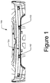
- Figure 1 illustrates a front view of a mounting component 100 of an automobile having a parking assist sensor (PAS) assembly 102 assembled therewith, according to an example of the present subject matter.
- the mounting component 100 can be a bumper, such as a rear bumper or a front bumper, of the automobile.
- the PAS assembly 102 installed in a rear or a front bumper can provide inputs to an on-board parking assistance system to facilitate a driver of the automobile in parking the automobile.
- the mounting component 100 can be any other part of the automobile where the PAS assembly 102 can be mounted for adequate operation for assisting the driver of the automobile.
- Figure 1 shows an inner surface 104 of the mounting component 100, such as the bumper, in which the PAS assembly 102 is shown in the assembled condition.
- the mounting component 100 may have a plurality of PAS assemblies 102 mounted thereon for parking assistance facility.
- the mounting component 100 may have one PAS assembly 102 mounted thereon.
- a single PAS assembly 102 may be adequate in providing the information to the on-board parking assistance system to achieve the operation.
- a portion of the PAS assembly 102 can be adequate in providing the information to the on-board parking assistance system to achieve the operation.
- the PAS assembly 102 can be designed in a way that the PAS assembly 102 can be mounted at any portion of the mounting component 100 having any contour or curvature.
- the PAS assembly 102 can be designed to conform to the shape of a portion of the mounting component 100 where the PAS assembly 102 is to be mounted, the portion referred to as mounting portion 206 hereinafter.
- Figure 2 illustrates a perspective view of the PAS assembly 102 in an assembled state with the mounting component 100, according to an example of the present subject matter.
- Figure 2 illustrates the inner surface 104 of the mounting component 100 and the PAS assembly 102 mounted thereon.
- the PAS assembly 102 can include a parking assist sensor (PAS) 202 and a parking assist sensor (PAS) holder 204 to hold the PAS 202.
- PAS assembly 102 can be provided with features to achieve three goals; firstly, features to secure the PAS 202; secondly, features to fix the PAS holder 204 to the mounting component 100; and third, features to adapt the PAS holder 204 to conform to the contours of the mounting portion 206 of the mounting component 100.
- the PAS 202 can be any sensor known in the art and used for the purposes of the parking assistance systems in automobiles.
- the PAS 202 can be a proximity sensor to determine when an object is at a predefined distance from the vehicle, and raise an alert in response.
- the PAS 202 can be an ultrasonic sensor or an electromagnetic sensor for operating as the proximity sensor.
- the PAS 202 can be an imaging device, such as a camera, which provides live feed to the driver of the automobile to allow the driver to view the distance of the automobile from an object in the vicinity and, accordingly, maneuver the automobile, say while parking.
- the PAS 202 can have a sensing portion (not shown) that implements the ultrasonic, electromagnetic, or imaging technology, for instance, for sensing the proximity of the PAS 202, and therefore, the automobile, to an object.
- the PAS holder 204 can be provided with features for coupling to the PAS 202.
- the PAS 202 can be have a body portion 208 which, in an example, may be provided with a fastener 210.
- the PAS holder 204 can be provided with one or more brackets 212 each having a complementary fastener 214 that complements the fastener 210 on the PAS 202.
- the number of fasteners 210 on the PAS 202 can be the same as the number of complementary fasteners 214, and accordingly, the number of brackets 212 can be provided on the PAS holder 204.
- the complementary fastener 214 can receive the fastener 210 of the PAS 202 to latch therewith.
- the fastener 210 can be a snap-fit lock whereas the complementary fastener 214 can be a slot to receive the snap-fit lock.
- the fastener 210 and the complementary fastener 214 can be designed as other types of fasteners known in the art.
- Other features of the PAS holder 204 are explained with reference to Figure 3A to Figure 5 .
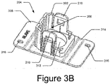
- Figure 3A , Figure 3B , and Figure 3C illustrate various perspective views of the PAS holder 204, according to an example of the present subject matter.
- the PAS holder 204 can either be a master holder, i.e., designed for holding a master PAS, or can be a slave holder, i.e., designed for holding a slave PAS.
- Figure 3A and Figure 3B illustrate the PAS holder 204 as a slave holder
- Figure 3C illustrates the PAS holder 204 as a master holder.
- Figure 3A , Figure 3B , and Figure 3C are described in conjunction with each other, in no particular order.
- the body portion 208 of the PAS holder 204 can be provided with a railing 302 having one or more grooves 304 that conform to the shape of the PAS 202 to accommodate the PAS 202.
- a width of the grooves 304 of the railing 302 can be broad.
- a broad slot 306 is formed between the brackets 212 and the railing 302 in the PAS holder 204. The broad slot 306 can accommodate the slave sensor which is broader in construction than the master sensor.
- the width of the grooves 304 of the railing 302 can be narrower than the width in case of the PAS holder 204 formed as the slave holder. Therefore, the PAS holder 204 when formed as the master holder can include a narrow slot 306 for accommodating the narrowly constructed master sensor.
- one of the terminal edges 308 of the railing 302 is formed as being straight from a wall part 310 of the railing 302, while the other has a structure similar to that as shown in Figure 3A and Figure 3B , i.e. when the PAS holder 204 is the slave holder.
- the PAS holder 204 can further be provided with an aperture 312.
- the aperture 312 can be formed as having substantially the same shape as that of the sensing portion of the PAS 202, with due consideration to fitments and tolerances. In other cases, however, the aperture 312 can be shaped to accommodate the sensing portion of the PAS 202 in such a manner that the PAS 202 can operate in an effective manner. For instance, the aperture 312 can be shaped factoring in that the effectiveness or operability of the PAS 202 in terms of the sensing ability is not hindered.
- the PAS holder 204 can be provided with features for allowing the PAS holder 204 to be able to match the shape and contours of the mounting portion 206 of the mounting component 100. Accordingly, in one aspect, the PAS holder 204 can be provided with a live hinge 314.
- the live hinge 314 can be provided in the body portion 208 to impart flexibility to the PAS holder 204, in order for the body portion 208 to achieve the aforementioned purpose.
- the PAS holder 204 can be provided with more than one live hinge 314. For instance, in the example shown in Figure 3A , Figure 3B , and Figure 3C , the PAS holder 204 can be provided with two live hinges 314, one live hinge 314 on either side of the aperture 312.
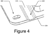
- Figure 4 illustrates a close-up view of the live hinge 314 formed in the body portion 208 of the PAS holder 204, according to an example of the present subject matter.
- the live hinge 314 can be formed by removing material from the body portion 208 at the location of the live hinge 314. Therefore, in said example, the live hinge 314 can be formed by designing the body portion 208 to have a lower cross-sectional thickness at the point of forming the live hinge 314 than a cross-sectional thickness at the rest of the body portion 208. In other words, the live hinge 314 can have a lower cross-sectional thickness in comparison to the body potion 208.
- the live hinge 314 can be shaped as a depression 402 in the body portion 208.
- the live hinge 314 can be designed in other ways, so as to achieve the function of having a flexible body portion 208 of the PAS holder 204 that can contour according to the contour of the mounting portion 206 of the mounting component 100.
- the live hinge 314 can be provided in the body portion 208 along a major dimension of the body portion 208, such as a length, so as to provide maximum flexibility to the PAS holder 204.
- the location of the live hinge 314 is determined in the body portion 208, such that the live hinge 314 allows maximum flexibility of the body portion 208 along the major dimension of the PAS holder 204.
- the number of live hinges 314 that can be provided in the PAS holder 204 can be based on, for example, the contour of the mounting portion 206.
- the PAS holder 204 can have a large number of live hinges 314 so that the PAS holder 204 can be flexible enough to match the contours of the mounting portion 206 and be used to adequately mount the PAS holder 204 to the mounting component 100.
- the PAS holder 204 can be provided with features for coupling to the mounting component 100.
- the body portion 208 of the PAS holder 204 can have a plurality of mounting holes 316 to allow the PAS holder 204 to couple to the mounting component 100.
- each mounting hole 316 can be designed to have a self-locking feature.
- each mounting hole 316 can be designed to cooperate with a snap locking feature (not shown) on the mounting component 100.
- the mounting hole 316 can create a snap-fit lock with the snap locking feature on the mounting component 100 for coupling the PAS holder 204 to the mounting component 100.
- other types of self-locking type fastening can be used.
- the PAS holder 204 can be designed to be fixed to the mounting component 100 without the use of any additional fasteners.
- the other example of the PAS holder 204 is illustrated in Figure 5 .
- the PAS holder 204 can have a mating surface 502 which can be used to couple the PAS holder 204 to the mounting component 100.
- the mating surface 502 in the example shown in Figure 5 , can be the surface of the body portion 208 opposite to the surface on which the brackets 212 and the railing 302 is provided.
- the mating surface 502 can allow the PAS holder 502 to be coupled to the mounting component 100 without any fasteners.
- the mating surface 502 can have an adhesive 504 to couple the PAS holder 204 to the mounting component 100.
- the adhesive 504 can be an industrial-grade tape covered by a peel-able cover, provided on the entire mating surface 502.
- the adhesive 504 can be selectively provided on the mating surface 502 so that the PAS holder 204 can be fixed with adequate strength.
- the manufacturing of the PAS holder s204 can be efficient as the PAS holder 204 does not require any fastening means, such as holes, thereby reducing one step in the manufacturing process.
- the assembly of the PAS holder 204 also becomes efficient as the mounting of the PAS holder 204 can be done simply by removing the peel-able cover from the adhesive 504 and fixing the PAS holder 204 to the mounting component 100.
Landscapes
- Engineering & Computer Science (AREA)
- General Engineering & Computer Science (AREA)
- Mechanical Engineering (AREA)
- Measurement Of Velocity Or Position Using Acoustic Or Ultrasonic Waves (AREA)
- Fittings On The Vehicle Exterior For Carrying Loads, And Devices For Holding Or Mounting Articles (AREA)
Abstract
Description
- With developments in automotive technology, automobiles are, typically, provided with facilities that allow the automobile as well as the occupants to be aware of surroundings, such as obstacles, object, and pedestrians in proximity of the automobile. Accordingly, on-board automotive systems may use such facilities for enhanced performance as well as safety of the automobile. One such facility may employ a sensor system to obtain information from a surrounding environment, for example, to alert a driver under certain circumstances, such as when the automobile is less than a predetermined distance from an object or obstacle. For instance, an automobile parking assistance system may include a parking assist sensor (PAS) to warn the driver if the automobile is approaching an object when being parked.
- The detailed description is provided with reference to the accompanying figures. It should be noted that the description and the figures are merely examples of the present subject matter and are not meant to represent the subject matter itself.
-
Figure 1 illustrates a front view of a mounting component of an automobile having a parking assist sensor (PAS) assembly assembled therewith, according to an example of the present subject matter. -
Figure 2 illustrates a perspective view of the PAS assembly in an assembled state, according to an example of the present subject matter. -
Figure 3A ,Figure 3B , andFigure 3C illustrates perspective views of a PAS holder of the PAS assembly, according to an example of the present subject matter. -
Figure 4 illustrates a magnified view of the PAS holder, according to the present subject matter. -
Figure 5 illustrates another perspective view of the PAS holder, according to an example of the present subject matter. - Throughout the drawings, identical reference numbers designate similar elements, but may not designate identical elements. The figures are not necessarily to scale, and the size of some parts may be exaggerated to more clearly illustrate the example shown. Moreover, the drawings provide examples and/or implementations consistent with the description; however, the description is not limited to the examples and/or implementations provided in the drawings.
- Amongst other safety facilities, automobiles may be provided with parking assistance systems as a safety feature to provide protection to pedestrians as well as the automobile from any impacts during parking of the automobile. For instance, a parking assist sensor (PAS) may be an ultrasonic sensor which are, generally, used in multiples and capable of determining a distance between the automobile and an object. Accordingly, the parking assistance system, using the PASs, can raise an alert for a driver of the automobile. The PASs may be deployed in a bumper, for instance, the rear and/or the front bumper, of the automobile, the PASs positioned in an area between the bumper and a chassis of the automobile. In other words, the PASs may be deployed on an inner surface of the bumper and only a sensing portion of the PASs may be exposed when viewed from a direction of an outer surface of the bumper.
- In certain cases, a holder may be employed for mounting the PAS to the bumper. For instance, the holder may have a slot in which the PAS is fitted and a hole through which the sensing portion of the PAS is exposed. The holder is then mounted to the bumper, usually, by ultrasonic welding. The holders so used for mounting the PASs are manufactured to specifically follow the contour of the bumper. In other words, the holder for each PAS is designed to complement the shape of the portion of the bumper to which the PAS holder is to be mounted, so that the PAS holder can be easily mounted to the bumper.
- Therefore, if four PAS are deployed as part of the parking assistance system, each of the holders for the four PAS may have to be designed and manufactured differently, in accordance with the shape of the portion of the bumper on which that PAS holder is to be mounted. Accordingly, manufacturing of such PAS holder may be costly as each different shape may involve a different tooling. In addition, the tolerances while manufacturing the PAS holders have to be strictly adhered to given the conformity with the shape of the portion of the bumper. Any deviation from the tolerances may render the manufactured PAS holders unusable. As a result, the manufacturing for such PAS holders may involve a considerable amount of wastage.
- Approaches and aspects relating to a parking assist sensor (PAS) holder and a parking assist sensor (PAS) assembly are described. According to an aspect, the PAS holder is designed in a way that the same PAS holder can be accommodated at any position on a mounting component, such as a bumper, irrespective of a shape of the mounting component at that position. In addition, the PAS holder can be conveniently mounted to the mounting component without requiring any complicated procedures, such as ultrasonic welding.
- In an example, the parking assist sensor (PAS) holder has a body portion which is provided with features for holding the PAS as well as the design features as mentioned previously. In one example, as part of the former, i.e., features for holding the PAS, the body portion includes a bracket to couple the PAS to it and an aperture for accommodating a sensing portion of the PAS. Further, as part of the latter, i.e., design features for adapting the PAS holder for use with any contour of the mounting component, the body portion includes one or more live hinges for providing flexibility to the body portion, so that the body portion can flex and bend to match a curvature of a mounting component, such as the bumper, for mounting the PAS.
- In one example, the live hinge can be formed by reducing a material in the portion of the live hinge so that the live hinge can have a lower cross-sectional thickness than a cross-sectional thickness of the body portion. Such a design achieves the flexibility of the PAS holder and at the same time reduces the cost of production of the PAS holder by reducing the material used for manufacturing thereon. In other examples, however, the live hinge can be provided in the PAS holder in other ways, so as to provide bending properties to the PAS holder. As mentioned previously, the flexibility or bending ability of the PAS holder allows the PAS holder to conform to any shape of the mounting component to which the PAS is to be mounted.
- In addition, the PAS holder can be provided with features to allow the PAS holder to be easily mounted to the mounting component. Accordingly, in one case, the body portion can have a mating surface which is adapted to mate with a complementary mating surface on the mounting component to couple the PAS holder to the mounting component. In said case, the mating surface can be provided with an adhesive to couple the PAS holder the mounting component. Therefore, in an example, PAS holder can be formed as a stick-on type component with an adhesive on the mating surface covered by a peel-able cover. For deploying, the peel-able cover can be removed and the PAS holder can be fixed to the mounting component. In addition, with the flexibility of the body portion of the PAS holder, the PAS holder is able to adequately bond with the mounting component using the adhesive. Accordingly, the assemblage of the PAS holder to the mounting component involves less time and is, therefore, productive.
- In another case, the PAS holder can be coupled to the mounting component using another type of fastening mechanism. In said case, the body portion can be provided with a plurality of mounting holes, each of the mounting holes having a self-locking feature. In other words, the mounting holes can have a feature that can cooperate with a complementary locking feature on the mounting component to lock the PAS holder with the mounting component. In addition, the mounting holes can serve the purpose of locating the PAS holder with respect to the complementary locking feature on the mounting component, thereby making the assembly convenient and efficient.
- The above aspects are further illustrated in the figures and described in the corresponding description below. It should be noted that the description and figures merely illustrate principles of the present subject matter. Therefore, various arrangements that encompass the principles of the present subject matter, although not explicitly described or shown herein, may be devised from the description and are included within its scope. Additionally, the word "coupled" is used throughout for clarity of the description and may include either a direct connection or an indirect connection.
-
Figure 1 illustrates a front view of amounting component 100 of an automobile having a parking assist sensor (PAS)assembly 102 assembled therewith, according to an example of the present subject matter. In said example, themounting component 100 can be a bumper, such as a rear bumper or a front bumper, of the automobile. Accordingly, in said example, the PASassembly 102 installed in a rear or a front bumper can provide inputs to an on-board parking assistance system to facilitate a driver of the automobile in parking the automobile. In other examples, however, themounting component 100 can be any other part of the automobile where thePAS assembly 102 can be mounted for adequate operation for assisting the driver of the automobile. - As an example,
Figure 1 shows aninner surface 104 of themounting component 100, such as the bumper, in which thePAS assembly 102 is shown in the assembled condition. As illustrated inFigure 1 , themounting component 100 may have a plurality ofPAS assemblies 102 mounted thereon for parking assistance facility. However, in another example, themounting component 100 may have onePAS assembly 102 mounted thereon. In such a case, asingle PAS assembly 102 may be adequate in providing the information to the on-board parking assistance system to achieve the operation. Further, as shown in the front view of the mountingcomponent 100 ofFigure 1 , a portion of thePAS assembly 102 can - According to an aspect, the
PAS assembly 102 can be designed in a way that thePAS assembly 102 can be mounted at any portion of the mountingcomponent 100 having any contour or curvature. In other words, thePAS assembly 102 can be designed to conform to the shape of a portion of the mountingcomponent 100 where thePAS assembly 102 is to be mounted, the portion referred to as mountingportion 206 hereinafter. -
Figure 2 illustrates a perspective view of thePAS assembly 102 in an assembled state with the mountingcomponent 100, according to an example of the present subject matter. As an example,Figure 2 illustrates theinner surface 104 of the mountingcomponent 100 and thePAS assembly 102 mounted thereon. ThePAS assembly 102 can include a parking assist sensor (PAS) 202 and a parking assist sensor (PAS)holder 204 to hold thePAS 202. the According to an aspect, thePAS assembly 102 can be provided with features to achieve three goals; firstly, features to secure thePAS 202; secondly, features to fix thePAS holder 204 to the mountingcomponent 100; and third, features to adapt thePAS holder 204 to conform to the contours of the mountingportion 206 of the mountingcomponent 100. - In said example, the
PAS 202 can be any sensor known in the art and used for the purposes of the parking assistance systems in automobiles. In one example, thePAS 202 can be a proximity sensor to determine when an object is at a predefined distance from the vehicle, and raise an alert in response. For instance, thePAS 202 can be an ultrasonic sensor or an electromagnetic sensor for operating as the proximity sensor. In another example, thePAS 202 can be an imaging device, such as a camera, which provides live feed to the driver of the automobile to allow the driver to view the distance of the automobile from an object in the vicinity and, accordingly, maneuver the automobile, say while parking. In the above examples, thePAS 202 can have a sensing portion (not shown) that implements the ultrasonic, electromagnetic, or imaging technology, for instance, for sensing the proximity of thePAS 202, and therefore, the automobile, to an object. - Further, as can be seen in
Figure 2 , thePAS holder 204 can be provided with features for coupling to thePAS 202. ThePAS 202 can be have abody portion 208 which, in an example, may be provided with afastener 210. Accordingly, thePAS holder 204 can be provided with one ormore brackets 212 each having acomplementary fastener 214 that complements thefastener 210 on thePAS 202. The number offasteners 210 on thePAS 202 can be the same as the number ofcomplementary fasteners 214, and accordingly, the number ofbrackets 212 can be provided on thePAS holder 204. Thecomplementary fastener 214 can receive thefastener 210 of thePAS 202 to latch therewith. For instance, thefastener 210 can be a snap-fit lock whereas thecomplementary fastener 214 can be a slot to receive the snap-fit lock. In other cases, thefastener 210 and thecomplementary fastener 214 can be designed as other types of fasteners known in the art. Other features of thePAS holder 204 are explained with reference toFigure 3A to Figure 5 . -
Figure 3A ,Figure 3B , andFigure 3C illustrate various perspective views of thePAS holder 204, according to an example of the present subject matter. In an example, thePAS holder 204 can either be a master holder, i.e., designed for holding a master PAS, or can be a slave holder, i.e., designed for holding a slave PAS. WhileFigure 3A andFigure 3B illustrate thePAS holder 204 as a slave holder,Figure 3C illustrates thePAS holder 204 as a master holder. For the purposes of brevity and ease of understanding,Figure 3A ,Figure 3B , andFigure 3C are described in conjunction with each other, in no particular order. - In addition to the
brackets 212, to accommodate thePAS 202, thebody portion 208 of thePAS holder 204 can be provided with arailing 302 having one ormore grooves 304 that conform to the shape of thePAS 202 to accommodate thePAS 202. As shown inFigure 3A andFigure 3B in which thePAS holder 204 is designed as the slave holder as an example, a width of thegrooves 304 of therailing 302 can be broad. Accordingly, abroad slot 306 is formed between thebrackets 212 and therailing 302 in thePAS holder 204. Thebroad slot 306 can accommodate the slave sensor which is broader in construction than the master sensor. On the other hand, when thePAS holder 204 is formed as the master holder, as shown as an example, inFigure 3C , the width of thegrooves 304 of therailing 302 can be narrower than the width in case of thePAS holder 204 formed as the slave holder. Therefore, thePAS holder 204 when formed as the master holder can include anarrow slot 306 for accommodating the narrowly constructed master sensor. - The difference in the construction of the
railing 302 in case of thePAS holder 204 designed as the slave holder and incase of thePAS holder 204 designed as the master holder can be appreciated by reference to and comparison ofFigure 3A orFigure 3B andFigure 3C . As can be seen inFigure 3A andFigure 3B , therailing 302 at bothterminal edges 308 are formed as a being drawn towards a periphery of the two ends. In other words, the terminal edges of therailing 302 are beveled to have a broad width. On the other, in comparison, as shown inFigure 3C , one of theterminal edges 308 of therailing 302 is formed as being straight from a wall part 310 of therailing 302, while the other has a structure similar to that as shown inFigure 3A andFigure 3B , i.e. when thePAS holder 204 is the slave holder. - In addition, to accommodate the sensing portion of the
PAS 202 so that the sensing portion is appropriately directed for adequate operation, thePAS holder 204 can further be provided with anaperture 312. Theaperture 312 can be formed as having substantially the same shape as that of the sensing portion of thePAS 202, with due consideration to fitments and tolerances. In other cases, however, theaperture 312 can be shaped to accommodate the sensing portion of thePAS 202 in such a manner that thePAS 202 can operate in an effective manner. For instance, theaperture 312 can be shaped factoring in that the effectiveness or operability of thePAS 202 in terms of the sensing ability is not hindered. - Further, as mentioned previously, the
PAS holder 204 can be provided with features for allowing thePAS holder 204 to be able to match the shape and contours of the mountingportion 206 of the mountingcomponent 100. Accordingly, in one aspect, thePAS holder 204 can be provided with alive hinge 314. Thelive hinge 314 can be provided in thebody portion 208 to impart flexibility to thePAS holder 204, in order for thebody portion 208 to achieve the aforementioned purpose. In an example, thePAS holder 204 can be provided with more than onelive hinge 314. For instance, in the example shown inFigure 3A ,Figure 3B , andFigure 3C , thePAS holder 204 can be provided with twolive hinges 314, onelive hinge 314 on either side of theaperture 312. -
Figure 4 illustrates a close-up view of thelive hinge 314 formed in thebody portion 208 of thePAS holder 204, according to an example of the present subject matter. According to said example, to achieve a flexibility of thebody portion 208 at thelive hinge 314, thelive hinge 314 can be formed by removing material from thebody portion 208 at the location of thelive hinge 314. Therefore, in said example, thelive hinge 314 can be formed by designing thebody portion 208 to have a lower cross-sectional thickness at the point of forming thelive hinge 314 than a cross-sectional thickness at the rest of thebody portion 208. In other words, thelive hinge 314 can have a lower cross-sectional thickness in comparison to thebody potion 208. Therefore, thelive hinge 314 can be shaped as adepression 402 in thebody portion 208. In other examples, thelive hinge 314 can be designed in other ways, so as to achieve the function of having aflexible body portion 208 of thePAS holder 204 that can contour according to the contour of the mountingportion 206 of the mountingcomponent 100. - In one example, the
live hinge 314 can be provided in thebody portion 208 along a major dimension of thebody portion 208, such as a length, so as to provide maximum flexibility to thePAS holder 204. In other words, the location of thelive hinge 314 is determined in thebody portion 208, such that thelive hinge 314 allows maximum flexibility of thebody portion 208 along the major dimension of thePAS holder 204. Accordingly, the number oflive hinges 314 that can be provided in thePAS holder 204 can be based on, for example, the contour of the mountingportion 206. For instance, if the mountingportion 206 has a large number of contours, then thePAS holder 204 can have a large number oflive hinges 314 so that thePAS holder 204 can be flexible enough to match the contours of the mountingportion 206 and be used to adequately mount thePAS holder 204 to the mountingcomponent 100. - In addition to conforming to the contours, the
PAS holder 204 can be provided with features for coupling to the mountingcomponent 100. Accordingly, in the example shown inFigures 3A ,3B , and3C , thebody portion 208 of thePAS holder 204 can have a plurality of mountingholes 316 to allow thePAS holder 204 to couple to the mountingcomponent 100. According to an aspect, each mountinghole 316 can be designed to have a self-locking feature. In an example, as part of the self-locking feature, each mountinghole 316 can be designed to cooperate with a snap locking feature (not shown) on the mountingcomponent 100. Accordingly, for assembly, the mountinghole 316 can create a snap-fit lock with the snap locking feature on the mountingcomponent 100 for coupling thePAS holder 204 to the mountingcomponent 100. In other example, other types of self-locking type fastening can be used. - According to another example, the
PAS holder 204 can be designed to be fixed to the mountingcomponent 100 without the use of any additional fasteners. The other example of thePAS holder 204 is illustrated inFigure 5 . Accordingly, in said example, thePAS holder 204 can have amating surface 502 which can be used to couple thePAS holder 204 to the mountingcomponent 100. Themating surface 502, in the example shown inFigure 5 , can be the surface of thebody portion 208 opposite to the surface on which thebrackets 212 and therailing 302 is provided. As mentioned, themating surface 502 can allow thePAS holder 502 to be coupled to the mountingcomponent 100 without any fasteners. Accordingly, themating surface 502 can have an adhesive 504 to couple thePAS holder 204 to the mountingcomponent 100. In an example, the adhesive 504 can be an industrial-grade tape covered by a peel-able cover, provided on theentire mating surface 502. In another example, the adhesive 504 can be selectively provided on themating surface 502 so that thePAS holder 204 can be fixed with adequate strength. With thePAS holder 204 designed as explained with reference toFigure 5 , the manufacturing of the PAS holder s204 can be efficient as thePAS holder 204 does not require any fastening means, such as holes, thereby reducing one step in the manufacturing process. At the same time, the assembly of thePAS holder 204 also becomes efficient as the mounting of thePAS holder 204 can be done simply by removing the peel-able cover from the adhesive 504 and fixing thePAS holder 204 to the mountingcomponent 100. - Although examples for the
PAS holder 204 for a glove compartment have been described in language specific to structural features and/or methods, it is to be understood that the appended claims are not limited to the specific features described. Rather, the specific features are disclosed as examples of thePAS holder 204.
Claims (10)
- A parking assist sensor (PAS) holder comprising:
a body portion comprising,a bracket to couple a parking assist sensor (PAS) thereto;an aperture for accommodating a sensing portion of the PAS; andat least one live hinge for providing flexibility to the body portion to match a curvature of a mounting component for mounting the PAS. - The PAS holder as claimed in claim 1, wherein the at least one live hinge is a formed as having a lower cross-sectional thickness than a cross-sectional thickness of the body portion.
- The PAS holder as claimed in claim 1, wherein the body portion comprises a mating surface to couple the PAS holder to the mounting component, the mating surface having an adhesive to adapt the body portion to couple to the mounting component.
- The PAS holder as claimed in claim 1, wherein the body portion further comprises a plurality of mounting holes to adapt the PAS holder to couple to the mounting component, wherein each of the plurality of mounting holes has a self-locking feature.
- The PAS assembly as claimed in claim 1, wherein the PAS holder is one of a master holder and a slave holder.
- A parking assist sensor (PAS) assembly comprising:a parking assist sensor (PAS) comprising a sensing portion, the PAS further having a fastener; anda parking assist sensor (PAS) holder to hold the PAS, the PAS holder comprising a body portion comprising,
a bracket having a complementary fastener to latch with the fastener on the PAS;
an aperture for accommodating the sensing portion of the PAS; and
at least one live hinge for providing flexibility to the PAS holder to match a curvature of a mounting component. - The PAS assembly as claimed in claim 6, wherein the at least one live hinge is a formed as having a lower cross-section thickness than a cross-sectional thickness of the body portion.
- The PAS assembly as claimed in claim 6, wherein the body portion comprises a mating surface to couple the PAS holder to the mounting component, the mating surface having an adhesive to adapt the body portion to couple to the mounting component.
- The PAS assembly as claimed in claim 6, wherein the body portion further comprises a plurality of mounting holes to adapt the PAS holder to couple to the mounting component, wherein each of the plurality of mounting holes has a self-locking feature.
- The PAS assembly as claimed in claim 6, wherein the PAS holder is one of a master holder and a slave holder.
Applications Claiming Priority (1)
| Application Number | Priority Date | Filing Date | Title |
|---|---|---|---|
| IN201821030986 | 2018-08-18 |
Publications (2)
| Publication Number | Publication Date |
|---|---|
| EP3611059A1 true EP3611059A1 (en) | 2020-02-19 |
| EP3611059B1 EP3611059B1 (en) | 2022-08-03 |
Family
ID=67659111
Family Applications (1)
| Application Number | Title | Priority Date | Filing Date |
|---|---|---|---|
| EP19192120.4A Not-in-force EP3611059B1 (en) | 2018-08-18 | 2019-08-16 | Parking assist sensor holder |
Country Status (1)
| Country | Link |
|---|---|
| EP (1) | EP3611059B1 (en) |
Cited By (1)
| Publication number | Priority date | Publication date | Assignee | Title |
|---|---|---|---|---|
| GB2596526A (en) * | 2020-06-26 | 2022-01-05 | Jaguar Land Rover Ltd | A sensor holder for a vehicle bumper |
Citations (8)
| Publication number | Priority date | Publication date | Assignee | Title |
|---|---|---|---|---|
| DE19621964A1 (en) * | 1996-05-31 | 1997-12-18 | Daimler Benz Ag | Variable mounting device especially for ultrasonic sensor on vehicle overrider |
| DE19939747A1 (en) * | 1999-08-21 | 2001-03-01 | Valeo Schalter & Sensoren Gmbh | Attachment device for attaching ultrasonic transducers to motor vehicles has sleeve-shaped part for accommodating transducer, mounting section with opening for holder part held by ring |
| US6508325B1 (en) * | 2000-02-28 | 2003-01-21 | Paul M. Schwarz | Mounting for proximity radar |
| WO2006021072A1 (en) * | 2003-09-04 | 2006-03-02 | Decoma International Inc. | Fascia for motor vehicle with integral component mounting and a method of making the same |
| US20080117080A1 (en) * | 2006-11-21 | 2008-05-22 | Kudelko Conrad M | Non-opaque external parking aid sensor bezels |
| DE102011105051A1 (en) * | 2011-06-20 | 2012-12-20 | Volkswagen Ag | Ultrasonic sensor device for a vehicle and arrangement with such an ultrasonic sensor device |
| EP2610114A1 (en) * | 2011-12-28 | 2013-07-03 | REHAU AG + Co | Holding device for holding and securing an electronic unit behind a trim part of a motor vehicle and a corresponding trim with a holding device |
| EP3258289A1 (en) * | 2016-06-13 | 2017-12-20 | Robert Bosch GmbH | Method for attaching a holder for one sensor on a cladding for a means of locomotion |
-
2019
- 2019-08-16 EP EP19192120.4A patent/EP3611059B1/en not_active Not-in-force
Patent Citations (8)
| Publication number | Priority date | Publication date | Assignee | Title |
|---|---|---|---|---|
| DE19621964A1 (en) * | 1996-05-31 | 1997-12-18 | Daimler Benz Ag | Variable mounting device especially for ultrasonic sensor on vehicle overrider |
| DE19939747A1 (en) * | 1999-08-21 | 2001-03-01 | Valeo Schalter & Sensoren Gmbh | Attachment device for attaching ultrasonic transducers to motor vehicles has sleeve-shaped part for accommodating transducer, mounting section with opening for holder part held by ring |
| US6508325B1 (en) * | 2000-02-28 | 2003-01-21 | Paul M. Schwarz | Mounting for proximity radar |
| WO2006021072A1 (en) * | 2003-09-04 | 2006-03-02 | Decoma International Inc. | Fascia for motor vehicle with integral component mounting and a method of making the same |
| US20080117080A1 (en) * | 2006-11-21 | 2008-05-22 | Kudelko Conrad M | Non-opaque external parking aid sensor bezels |
| DE102011105051A1 (en) * | 2011-06-20 | 2012-12-20 | Volkswagen Ag | Ultrasonic sensor device for a vehicle and arrangement with such an ultrasonic sensor device |
| EP2610114A1 (en) * | 2011-12-28 | 2013-07-03 | REHAU AG + Co | Holding device for holding and securing an electronic unit behind a trim part of a motor vehicle and a corresponding trim with a holding device |
| EP3258289A1 (en) * | 2016-06-13 | 2017-12-20 | Robert Bosch GmbH | Method for attaching a holder for one sensor on a cladding for a means of locomotion |
Cited By (2)
| Publication number | Priority date | Publication date | Assignee | Title |
|---|---|---|---|---|
| GB2596526A (en) * | 2020-06-26 | 2022-01-05 | Jaguar Land Rover Ltd | A sensor holder for a vehicle bumper |
| GB2596526B (en) * | 2020-06-26 | 2022-09-21 | Jaguar Land Rover Ltd | A sensor holder for a vehicle bumper |
Also Published As
| Publication number | Publication date |
|---|---|
| BR102019016994A2 (en) | 2020-05-05 |
| EP3611059B1 (en) | 2022-08-03 |
Similar Documents
| Publication | Publication Date | Title |
|---|---|---|
| US11221408B2 (en) | Radar unit assembly for a vehicle | |
| US10518728B2 (en) | Sensor protector and vehicle equipped therewith | |
| US10024970B2 (en) | Sensor housing assembly for attachment to a motor vehicle | |
| JP4903044B2 (en) | Plastic panel attached to automobile | |
| US8910986B1 (en) | Bonded and rotatable vehicle sensor assembly | |
| US8414069B1 (en) | Vehicle lamp mounting assembly | |
| RU147025U1 (en) | CAR VEHICLE ELEMENT WITH SHOCK SENSOR | |
| JP7188300B2 (en) | Sensor mounting structure | |
| CN112550123A (en) | Vehicle front end tie-down assembly | |
| MX2015001665A (en) | Vehicle sensor assembly with lever assist. | |
| CN106184059A (en) | Controller mounting structure | |
| US9868334B2 (en) | Installation structure for vehicle-mounted device | |
| EP3611059B1 (en) | Parking assist sensor holder | |
| JP3695245B2 (en) | Ultrasonic sensor mounting structure | |
| US20250237736A1 (en) | Radar system for vehicle with offset electronics | |
| US11180088B2 (en) | Mounting assembly for an exterior attachment device, rearview device and motor vehicle | |
| US20230234507A1 (en) | Exterior rear view assembly for road vehicles and method of manufacturing an exterior rear view assembly for road vehicles | |
| CN110893825A (en) | External sensor installation structure | |
| CN217170620U (en) | Vehicle-mounted radar arrangement and installation structure and automobile | |
| BR102019016994B1 (en) | Parking Assist Sensor Bracket and Parking Assist Sensor Assembly | |
| US11648904B2 (en) | Apparatus for coupling airbag module to steering wheel | |
| JP7279809B2 (en) | Roof panels and vehicle roof structures | |
| JP4817122B2 (en) | Vehicle interior trim | |
| EP2998168A1 (en) | Holder for a blind spot sensor system of a motor vehicle, a bumper valence of a motor vehicle and a method of mounting a blind spot sensor module to a motor vehicle | |
| JP2012162167A (en) | Bumper holder |
Legal Events
| Date | Code | Title | Description |
|---|---|---|---|
| PUAI | Public reference made under article 153(3) epc to a published international application that has entered the european phase |
Free format text: ORIGINAL CODE: 0009012 |
|
| STAA | Information on the status of an ep patent application or granted ep patent |
Free format text: STATUS: THE APPLICATION HAS BEEN PUBLISHED |
|
| AK | Designated contracting states |
Kind code of ref document: A1 Designated state(s): AL AT BE BG CH CY CZ DE DK EE ES FI FR GB GR HR HU IE IS IT LI LT LU LV MC MK MT NL NO PL PT RO RS SE SI SK SM TR |
|
| AX | Request for extension of the european patent |
Extension state: BA ME |
|
| STAA | Information on the status of an ep patent application or granted ep patent |
Free format text: STATUS: REQUEST FOR EXAMINATION WAS MADE |
|
| 17P | Request for examination filed |
Effective date: 20200805 |
|
| RBV | Designated contracting states (corrected) |
Designated state(s): AL AT BE BG CH CY CZ DE DK EE ES FI FR GB GR HR HU IE IS IT LI LT LU LV MC MK MT NL NO PL PT RO RS SE SI SK SM TR |
|
| GRAP | Despatch of communication of intention to grant a patent |
Free format text: ORIGINAL CODE: EPIDOSNIGR1 |
|
| STAA | Information on the status of an ep patent application or granted ep patent |
Free format text: STATUS: GRANT OF PATENT IS INTENDED |
|
| INTG | Intention to grant announced |
Effective date: 20220323 |
|
| GRAS | Grant fee paid |
Free format text: ORIGINAL CODE: EPIDOSNIGR3 |
|
| GRAA | (expected) grant |
Free format text: ORIGINAL CODE: 0009210 |
|
| STAA | Information on the status of an ep patent application or granted ep patent |
Free format text: STATUS: THE PATENT HAS BEEN GRANTED |
|
| AK | Designated contracting states |
Kind code of ref document: B1 Designated state(s): AL AT BE BG CH CY CZ DE DK EE ES FI FR GB GR HR HU IE IS IT LI LT LU LV MC MK MT NL NO PL PT RO RS SE SI SK SM TR |
|
| REG | Reference to a national code |
Ref country code: AT Ref legal event code: REF Ref document number: 1508499 Country of ref document: AT Kind code of ref document: T Effective date: 20220815 Ref country code: CH Ref legal event code: EP |
|
| REG | Reference to a national code |
Ref country code: DE Ref legal event code: R096 Ref document number: 602019017693 Country of ref document: DE |
|
| REG | Reference to a national code |
Ref country code: IE Ref legal event code: FG4D |
|
| REG | Reference to a national code |
Ref country code: LT Ref legal event code: MG9D |
|
| REG | Reference to a national code |
Ref country code: NL Ref legal event code: MP Effective date: 20220803 |
|
| PG25 | Lapsed in a contracting state [announced via postgrant information from national office to epo] |
Ref country code: SE Free format text: LAPSE BECAUSE OF FAILURE TO SUBMIT A TRANSLATION OF THE DESCRIPTION OR TO PAY THE FEE WITHIN THE PRESCRIBED TIME-LIMIT Effective date: 20220803 Ref country code: RS Free format text: LAPSE BECAUSE OF FAILURE TO SUBMIT A TRANSLATION OF THE DESCRIPTION OR TO PAY THE FEE WITHIN THE PRESCRIBED TIME-LIMIT Effective date: 20220803 Ref country code: PT Free format text: LAPSE BECAUSE OF FAILURE TO SUBMIT A TRANSLATION OF THE DESCRIPTION OR TO PAY THE FEE WITHIN THE PRESCRIBED TIME-LIMIT Effective date: 20221205 Ref country code: NO Free format text: LAPSE BECAUSE OF FAILURE TO SUBMIT A TRANSLATION OF THE DESCRIPTION OR TO PAY THE FEE WITHIN THE PRESCRIBED TIME-LIMIT Effective date: 20221103 Ref country code: NL Free format text: LAPSE BECAUSE OF FAILURE TO SUBMIT A TRANSLATION OF THE DESCRIPTION OR TO PAY THE FEE WITHIN THE PRESCRIBED TIME-LIMIT Effective date: 20220803 Ref country code: LV Free format text: LAPSE BECAUSE OF FAILURE TO SUBMIT A TRANSLATION OF THE DESCRIPTION OR TO PAY THE FEE WITHIN THE PRESCRIBED TIME-LIMIT Effective date: 20220803 Ref country code: LT Free format text: LAPSE BECAUSE OF FAILURE TO SUBMIT A TRANSLATION OF THE DESCRIPTION OR TO PAY THE FEE WITHIN THE PRESCRIBED TIME-LIMIT Effective date: 20220803 Ref country code: FI Free format text: LAPSE BECAUSE OF FAILURE TO SUBMIT A TRANSLATION OF THE DESCRIPTION OR TO PAY THE FEE WITHIN THE PRESCRIBED TIME-LIMIT Effective date: 20220803 Ref country code: ES Free format text: LAPSE BECAUSE OF FAILURE TO SUBMIT A TRANSLATION OF THE DESCRIPTION OR TO PAY THE FEE WITHIN THE PRESCRIBED TIME-LIMIT Effective date: 20220803 |
|
| REG | Reference to a national code |
Ref country code: AT Ref legal event code: MK05 Ref document number: 1508499 Country of ref document: AT Kind code of ref document: T Effective date: 20220803 |
|
| PG25 | Lapsed in a contracting state [announced via postgrant information from national office to epo] |
Ref country code: PL Free format text: LAPSE BECAUSE OF FAILURE TO SUBMIT A TRANSLATION OF THE DESCRIPTION OR TO PAY THE FEE WITHIN THE PRESCRIBED TIME-LIMIT Effective date: 20220803 Ref country code: IS Free format text: LAPSE BECAUSE OF FAILURE TO SUBMIT A TRANSLATION OF THE DESCRIPTION OR TO PAY THE FEE WITHIN THE PRESCRIBED TIME-LIMIT Effective date: 20221203 Ref country code: HR Free format text: LAPSE BECAUSE OF FAILURE TO SUBMIT A TRANSLATION OF THE DESCRIPTION OR TO PAY THE FEE WITHIN THE PRESCRIBED TIME-LIMIT Effective date: 20220803 Ref country code: GR Free format text: LAPSE BECAUSE OF FAILURE TO SUBMIT A TRANSLATION OF THE DESCRIPTION OR TO PAY THE FEE WITHIN THE PRESCRIBED TIME-LIMIT Effective date: 20221104 |
|
| REG | Reference to a national code |
Ref country code: CH Ref legal event code: PL |
|
| PG25 | Lapsed in a contracting state [announced via postgrant information from national office to epo] |
Ref country code: SM Free format text: LAPSE BECAUSE OF FAILURE TO SUBMIT A TRANSLATION OF THE DESCRIPTION OR TO PAY THE FEE WITHIN THE PRESCRIBED TIME-LIMIT Effective date: 20220803 Ref country code: RO Free format text: LAPSE BECAUSE OF FAILURE TO SUBMIT A TRANSLATION OF THE DESCRIPTION OR TO PAY THE FEE WITHIN THE PRESCRIBED TIME-LIMIT Effective date: 20220803 Ref country code: LU Free format text: LAPSE BECAUSE OF NON-PAYMENT OF DUE FEES Effective date: 20220816 Ref country code: LI Free format text: LAPSE BECAUSE OF NON-PAYMENT OF DUE FEES Effective date: 20220831 Ref country code: DK Free format text: LAPSE BECAUSE OF FAILURE TO SUBMIT A TRANSLATION OF THE DESCRIPTION OR TO PAY THE FEE WITHIN THE PRESCRIBED TIME-LIMIT Effective date: 20220803 Ref country code: CZ Free format text: LAPSE BECAUSE OF FAILURE TO SUBMIT A TRANSLATION OF THE DESCRIPTION OR TO PAY THE FEE WITHIN THE PRESCRIBED TIME-LIMIT Effective date: 20220803 Ref country code: CH Free format text: LAPSE BECAUSE OF NON-PAYMENT OF DUE FEES Effective date: 20220831 Ref country code: AT Free format text: LAPSE BECAUSE OF FAILURE TO SUBMIT A TRANSLATION OF THE DESCRIPTION OR TO PAY THE FEE WITHIN THE PRESCRIBED TIME-LIMIT Effective date: 20220803 |
|
| REG | Reference to a national code |
Ref country code: BE Ref legal event code: MM Effective date: 20220831 |
|
| REG | Reference to a national code |
Ref country code: DE Ref legal event code: R097 Ref document number: 602019017693 Country of ref document: DE |
|
| PG25 | Lapsed in a contracting state [announced via postgrant information from national office to epo] |
Ref country code: SK Free format text: LAPSE BECAUSE OF FAILURE TO SUBMIT A TRANSLATION OF THE DESCRIPTION OR TO PAY THE FEE WITHIN THE PRESCRIBED TIME-LIMIT Effective date: 20220803 Ref country code: MC Free format text: LAPSE BECAUSE OF FAILURE TO SUBMIT A TRANSLATION OF THE DESCRIPTION OR TO PAY THE FEE WITHIN THE PRESCRIBED TIME-LIMIT Effective date: 20220803 Ref country code: EE Free format text: LAPSE BECAUSE OF FAILURE TO SUBMIT A TRANSLATION OF THE DESCRIPTION OR TO PAY THE FEE WITHIN THE PRESCRIBED TIME-LIMIT Effective date: 20220803 |
|
| PLBE | No opposition filed within time limit |
Free format text: ORIGINAL CODE: 0009261 |
|
| STAA | Information on the status of an ep patent application or granted ep patent |
Free format text: STATUS: NO OPPOSITION FILED WITHIN TIME LIMIT |
|
| PG25 | Lapsed in a contracting state [announced via postgrant information from national office to epo] |
Ref country code: AL Free format text: LAPSE BECAUSE OF FAILURE TO SUBMIT A TRANSLATION OF THE DESCRIPTION OR TO PAY THE FEE WITHIN THE PRESCRIBED TIME-LIMIT Effective date: 20220803 |
|
| 26N | No opposition filed |
Effective date: 20230504 |
|
| P01 | Opt-out of the competence of the unified patent court (upc) registered |
Effective date: 20230606 |
|
| PG25 | Lapsed in a contracting state [announced via postgrant information from national office to epo] |
Ref country code: IE Free format text: LAPSE BECAUSE OF NON-PAYMENT OF DUE FEES Effective date: 20220816 Ref country code: FR Free format text: LAPSE BECAUSE OF NON-PAYMENT OF DUE FEES Effective date: 20221003 |
|
| PG25 | Lapsed in a contracting state [announced via postgrant information from national office to epo] |
Ref country code: SI Free format text: LAPSE BECAUSE OF FAILURE TO SUBMIT A TRANSLATION OF THE DESCRIPTION OR TO PAY THE FEE WITHIN THE PRESCRIBED TIME-LIMIT Effective date: 20220803 |
|
| PG25 | Lapsed in a contracting state [announced via postgrant information from national office to epo] |
Ref country code: BE Free format text: LAPSE BECAUSE OF NON-PAYMENT OF DUE FEES Effective date: 20220831 |
|
| PG25 | Lapsed in a contracting state [announced via postgrant information from national office to epo] |
Ref country code: HU Free format text: LAPSE BECAUSE OF FAILURE TO SUBMIT A TRANSLATION OF THE DESCRIPTION OR TO PAY THE FEE WITHIN THE PRESCRIBED TIME-LIMIT; INVALID AB INITIO Effective date: 20190816 |
|
| GBPC | Gb: european patent ceased through non-payment of renewal fee |
Effective date: 20230816 |
|
| PG25 | Lapsed in a contracting state [announced via postgrant information from national office to epo] |
Ref country code: CY Free format text: LAPSE BECAUSE OF FAILURE TO SUBMIT A TRANSLATION OF THE DESCRIPTION OR TO PAY THE FEE WITHIN THE PRESCRIBED TIME-LIMIT Effective date: 20220803 |
|
| PG25 | Lapsed in a contracting state [announced via postgrant information from national office to epo] |
Ref country code: MK Free format text: LAPSE BECAUSE OF FAILURE TO SUBMIT A TRANSLATION OF THE DESCRIPTION OR TO PAY THE FEE WITHIN THE PRESCRIBED TIME-LIMIT Effective date: 20220803 Ref country code: IT Free format text: LAPSE BECAUSE OF FAILURE TO SUBMIT A TRANSLATION OF THE DESCRIPTION OR TO PAY THE FEE WITHIN THE PRESCRIBED TIME-LIMIT Effective date: 20220803 |
|
| PG25 | Lapsed in a contracting state [announced via postgrant information from national office to epo] |
Ref country code: TR Free format text: LAPSE BECAUSE OF FAILURE TO SUBMIT A TRANSLATION OF THE DESCRIPTION OR TO PAY THE FEE WITHIN THE PRESCRIBED TIME-LIMIT Effective date: 20220803 |
|
| PG25 | Lapsed in a contracting state [announced via postgrant information from national office to epo] |
Ref country code: GB Free format text: LAPSE BECAUSE OF NON-PAYMENT OF DUE FEES Effective date: 20230816 |
|
| PG25 | Lapsed in a contracting state [announced via postgrant information from national office to epo] |
Ref country code: GB Free format text: LAPSE BECAUSE OF NON-PAYMENT OF DUE FEES Effective date: 20230816 Ref country code: BG Free format text: LAPSE BECAUSE OF FAILURE TO SUBMIT A TRANSLATION OF THE DESCRIPTION OR TO PAY THE FEE WITHIN THE PRESCRIBED TIME-LIMIT Effective date: 20220803 |
|
| PG25 | Lapsed in a contracting state [announced via postgrant information from national office to epo] |
Ref country code: MT Free format text: LAPSE BECAUSE OF FAILURE TO SUBMIT A TRANSLATION OF THE DESCRIPTION OR TO PAY THE FEE WITHIN THE PRESCRIBED TIME-LIMIT Effective date: 20220803 |
|
| PGFP | Annual fee paid to national office [announced via postgrant information from national office to epo] |
Ref country code: DE Payment date: 20240828 Year of fee payment: 6 |
|
| REG | Reference to a national code |
Ref country code: DE Ref legal event code: R119 Ref document number: 602019017693 Country of ref document: DE |