EP3610990B1 - Control method for a hand-held machine tool, handheld machine tool and system including the handheld machine tool and a stand - Google Patents
Control method for a hand-held machine tool, handheld machine tool and system including the handheld machine tool and a stand Download PDFInfo
- Publication number
- EP3610990B1 EP3610990B1 EP18188878.5A EP18188878A EP3610990B1 EP 3610990 B1 EP3610990 B1 EP 3610990B1 EP 18188878 A EP18188878 A EP 18188878A EP 3610990 B1 EP3610990 B1 EP 3610990B1
- Authority
- EP
- European Patent Office
- Prior art keywords
- hand
- control method
- frequency spectrum
- power tool
- rotating movement
- Prior art date
- Legal status (The legal status is an assumption and is not a legal conclusion. Google has not performed a legal analysis and makes no representation as to the accuracy of the status listed.)
- Active
Links
- 238000000034 method Methods 0.000 title claims description 47
- 238000001228 spectrum Methods 0.000 claims description 68
- 230000009993 protective function Effects 0.000 claims description 42
- 230000008859 change Effects 0.000 claims description 14
- 230000010354 integration Effects 0.000 claims description 14
- 230000001681 protective effect Effects 0.000 claims description 14
- 230000002123 temporal effect Effects 0.000 claims description 14
- 230000001133 acceleration Effects 0.000 claims description 7
- 238000001514 detection method Methods 0.000 claims description 5
- 230000006870 function Effects 0.000 description 9
- 238000004590 computer program Methods 0.000 description 7
- 238000001914 filtration Methods 0.000 description 6
- 230000009466 transformation Effects 0.000 description 6
- 238000005553 drilling Methods 0.000 description 5
- 238000005259 measurement Methods 0.000 description 4
- 230000004048 modification Effects 0.000 description 4
- 238000012986 modification Methods 0.000 description 4
- 230000008569 process Effects 0.000 description 4
- 230000001960 triggered effect Effects 0.000 description 4
- 238000012545 processing Methods 0.000 description 3
- 238000012935 Averaging Methods 0.000 description 2
- XEEYBQQBJWHFJM-UHFFFAOYSA-N Iron Chemical compound [Fe] XEEYBQQBJWHFJM-UHFFFAOYSA-N 0.000 description 2
- 230000001419 dependent effect Effects 0.000 description 2
- 238000010586 diagram Methods 0.000 description 2
- 238000003754 machining Methods 0.000 description 2
- 230000010355 oscillation Effects 0.000 description 2
- 239000000758 substrate Substances 0.000 description 2
- 230000002238 attenuated effect Effects 0.000 description 1
- 230000008901 benefit Effects 0.000 description 1
- 238000004891 communication Methods 0.000 description 1
- 230000006378 damage Effects 0.000 description 1
- 238000011156 evaluation Methods 0.000 description 1
- 230000003993 interaction Effects 0.000 description 1
- 229910052742 iron Inorganic materials 0.000 description 1
- 230000007246 mechanism Effects 0.000 description 1
- 230000003287 optical effect Effects 0.000 description 1
- 238000009527 percussion Methods 0.000 description 1
- 230000009467 reduction Effects 0.000 description 1
- 230000002829 reductive effect Effects 0.000 description 1
- 230000002787 reinforcement Effects 0.000 description 1
- 230000004044 response Effects 0.000 description 1
- 230000000717 retained effect Effects 0.000 description 1
- 230000036962 time dependent Effects 0.000 description 1
- 230000001131 transforming effect Effects 0.000 description 1
- 210000000707 wrist Anatomy 0.000 description 1
Images
Classifications
-
- B—PERFORMING OPERATIONS; TRANSPORTING
- B25—HAND TOOLS; PORTABLE POWER-DRIVEN TOOLS; MANIPULATORS
- B25F—COMBINATION OR MULTI-PURPOSE TOOLS NOT OTHERWISE PROVIDED FOR; DETAILS OR COMPONENTS OF PORTABLE POWER-DRIVEN TOOLS NOT PARTICULARLY RELATED TO THE OPERATIONS PERFORMED AND NOT OTHERWISE PROVIDED FOR
- B25F5/00—Details or components of portable power-driven tools not particularly related to the operations performed and not otherwise provided for
-
- B—PERFORMING OPERATIONS; TRANSPORTING
- B25—HAND TOOLS; PORTABLE POWER-DRIVEN TOOLS; MANIPULATORS
- B25H—WORKSHOP EQUIPMENT, e.g. FOR MARKING-OUT WORK; STORAGE MEANS FOR WORKSHOPS
- B25H1/00—Work benches; Portable stands or supports for positioning portable tools or work to be operated on thereby
- B25H1/0021—Stands, supports or guiding devices for positioning portable tools or for securing them to the work
Landscapes
- Engineering & Computer Science (AREA)
- Mechanical Engineering (AREA)
- Percussive Tools And Related Accessories (AREA)
Description
Die vorliegende Erfindung betrifft ein Steuerungsverfahren für eine Handwerkzeugmaschine, eine Handwerkzeugmaschine und ein System mit der Handwerkzeugmaschine und einem Ständer.The present invention relates to a control method for a handheld power tool, a handheld power tool and a system with the handheld power tool and a stand.
Handwerkzeugmaschinen, wie beispielsweise Bohrmaschinen, können eine Schutzfunktion aufweisen, welche einen Benutzer der Handwerkzeugmaschine vor einem zu großen auf das Gehäuse, insbesondere den Handgriff, rückwirkenden Drehmoment schützt. Die Schutzfunktion reduziert eine Drehmomentabgabe eines Motors der Handwerkzeugmaschine, wenn das rückwirkende Drehmoment einen bestimmten Grenzwert überschreitet. Wird die Handwerkzeugmaschine jedoch beim Betrieb nicht von einem Benutzer in der Hand gehalten, sondern von einem Ständer gehalten, ist es wünschenswert, die Schutzfunktion abzuschalten.Handheld power tools, such as drills, can have a protective function which protects a user of the handheld power tool from excessive torque acting back on the housing, in particular the handle. The protective function reduces a torque output of a motor of the handheld power tool when the retroactive torque exceeds a certain limit value. However, if the hand-held power tool is not held in the hand by a user during operation, but held by a stand, it is desirable to switch off the protective function.
Eine Handwerkzeugmaschine mit einer Schutzfunktion ist aus der
Vor diesem Hintergrund besteht die Aufgabe der vorliegenden Erfindung, ein Steuerungsverfahren für eine Handwerkzeugmaschine zu verbessern, eine verbesserte Handwerkzeugmaschine und ein System mit einer derartigen verbesserten Handwerkzeugmaschine und einem Ständer zu schaffen.Against this background, the object of the present invention is to improve a control method for a handheld power tool, to create an improved handheld power tool and a system with such an improved handheld power tool and a stand.
Gemäß einem ersten Aspekt wird ein Steuerungsverfahren für eine Handwerkzeugmaschine vorgeschlagen. Die Handwerkzeugmaschine weist eine Werkzeugaufnahme und einen Motor zum drehenden Antreiben der Werkzeugaufnahme um eine Arbeitsachse auf. Das Steuerungsverfahren weist einen Schritt des Erfassens einer Drehbewegung eines Gehäuses der Handwerkzeugmaschine um die Arbeitsachse auf. Das Steuerungsverfahren weist des Weiteren einen Schritt eines Auslösens einer Schutzfunktion auf zum Reduzieren einer Drehmomentabgabe des Motors, wenn die erfasste Drehbewegung um die Arbeitsachse einen bestimmten Grenzwert überschreitet. Das Steuerungsverfahren weist ferner einen Schritt eines Abschaltens der Schutzfunktion in Abhängigkeit einer charakteristischen Größe eines Frequenzspektrums einer erfassten Drehbewegung um die Arbeitsachse auf.According to a first aspect, a control method for a handheld power tool is proposed. The handheld power tool has a tool holder and a motor for driving the tool holder in rotation about a working axis. The control method has a step of detecting a rotary movement of a housing of the handheld power tool about the working axis. The control method furthermore has a step of triggering a protective function for reducing a torque output of the motor if the detected rotational movement about the working axis exceeds a specific limit value. The control method also has a step of switching off the protective function as a function of a characteristic variable of a frequency spectrum of a detected rotary movement about the working axis.
Die mit dem Steuerungsverfahren gesteuerte Handwerkzeugmaschine ist beispielsweise ein Bohrhammer, ein Kombihammer, ein Kernbohrer oder ein Schrauber. Die Werkzeugaufnahme der Handwerkzeugmaschine dient zum Einsetzen eines drehbaren Werkzeugs, z. B. eines Bohrers. Der Motor der Handwerkzeugmaschine dient insbesondere dazu, durch drehendes Antreiben der Werkzeugaufnahme um die Arbeitsachse das Werkzeug in eine Rotation um die Arbeitsachse zu versetzen. Durch die Rotation des Werkzeugs kann ein Gegenstand, wie beispielsweise ein Untergrund und/oder eine Wand, bearbeitet werden.The handheld power tool controlled with the control method is, for example, a rotary hammer, a combination hammer, a core drill or a screwdriver. The tool holder of the hand machine tool is used to insert a rotatable tool, for. B. a drill. The motor of the hand machine tool is used in particular to set the tool in rotation about the working axis by driving the tool holder in a rotating manner about the working axis. By rotating the tool, an object, such as a subsurface and / or a wall, can be processed.
In einem ersten Schritt des Steuerungsverfahrens wird die Drehbewegung des Gehäuses, insbesondere des Handgriffs, der Handwerkzeugmaschine um die Arbeitsachse erfasst. Beispielsweise erfasst ein Drehbewegungssensor der Handwerkzeugmaschine die Drehbewegung des Gehäuses. Eine solche Drehbewegung des Gehäuses kann insbesondere durch ein rückwirkendes Drehmoment des Werkzeugs und/oder der Werkzeugaufnahme verursacht werden, wenn das Werkzeug und/oder die Werkzeugaufnahme nicht vollständig von dem Gehäuse entkoppelt sind. Beispielsweise kann eine Wechselwirkung des Werkzeugs mit dem zu bearbeitenden Gegenstand durch ein rückwirkendes Drehmoment eine Drehbewegung des Gehäuses um die Arbeitsachse verursachen. Besonders bei einem Bearbeiten eines inhomogenen Gegenstands und/oder eines nicht nachgebenden Gegenstands mit der Handwerkzeugmaschine kann es zu einer Drehbewegung des Gehäuses kommen. Die Inhomogenität und/oder das Nichtnachgeben des Gegenstands kann insbesondere zu einer zeitlich veränderlichen Drehbewegung des Werkzeugs führen, welche wiederum durch das rückwirkende Drehmoment eine zeitlich veränderliche Drehbewegung des Gehäuses verursacht.In a first step of the control method, the rotary movement of the housing, in particular the handle, of the handheld power tool about the working axis is recorded. For example, a rotary motion sensor of the handheld power tool detects the rotary motion of the housing. Such a rotary movement of the housing can in particular be caused by a retroactive torque of the tool and / or the tool holder if the tool and / or the tool holder are not completely decoupled from the housing. For example, an interaction of the tool with the object to be machined can cause a rotational movement of the housing about the working axis through a retroactive torque. Particularly when machining an inhomogeneous object and / or a non-yielding object with the handheld power tool, a rotary movement of the housing can occur. The inhomogeneity and / or the non-yielding of the object can in particular lead to a temporally variable rotational movement of the tool, which in turn causes a temporally variable rotational movement of the housing due to the retroactive torque.
Die Drehbewegungen können Vibrationen des Handgriffs um eine Mittenlage umfassen. Die erfasste Drehbewegung des Gehäuses um die Arbeitsachse ist insbesondere eine zeitlich veränderliche Drehbewegung. Insbesondere wird durch das Erfassen der Drehbewegung die zeitliche Veränderung der Drehbewegung erfasst. Beispielsweise weist die erfasste Drehbewegung eine zeitlich veränderliche Winkelgeschwindigkeit, eine zeitlich veränderliche Drehzahl, ein zeitlich veränderliches Drehmoment und/oder eine zeitlich veränderliche Winkelauslenkung auf. Beispielsweise weist die erfasste Drehbewegung ein Abbremsen und Beschleunigen der Winkelgeschwindigkeit auf.The rotary movements can include vibrations of the handle about a central position. The detected rotational movement of the housing about the working axis is in particular a rotational movement that changes over time. In particular, the change in the rotational movement over time is recorded by detecting the rotary movement. For example, the detected rotary movement has an angular velocity that varies over time, a rotational speed that changes over time, a torque that changes over time and / or an angular deflection that changes over time. For example, the detected rotational movement has a braking and acceleration of the angular velocity.
In einem zweiten Schritt des Steuerungsverfahrens wird die Schutzfunktion zum Reduzieren der Drehmomentabgabe des Motors ausgelöst, wenn die erfasste Drehbewegung um die Arbeitsachse den bestimmten Grenzwert überschreitet.In a second step of the control method, the protective function for reducing the torque output of the motor is triggered when the detected rotary movement around the working axis exceeds the specific limit value.
Beispielsweise ermittelt eine Schutzeinrichtung und/oder eine Steuereinrichtung der Handwerkzeugmaschine, ob die erfasste Drehbewegung des Gehäuses um die Arbeitsachse den bestimmten Grenzwert überschreitet. Beispielsweise löst die Schutzeinrichtung und/oder die Steuereinrichtung bei einem Überschreiten des bestimmten Grenzwerts die Schutzfunktion aus.For example, a protective device and / or a control device of the handheld power tool determines whether the detected rotational movement of the housing about the working axis exceeds the specific limit value. For example, the protective device and / or the control device triggers the protective function when the specific limit value is exceeded.
Der bestimmte Grenzwert ist beispielsweise eine bestimmte Winkelgeschwindigkeit, eine bestimmte Drehzahl, ein bestimmtes Drehmoment und/oder eine bestimmte Winkelauslenkung. Dadurch, dass die Schutzfunktion zum Reduzieren der Drehmomentabgabe des Motors ausgelöst wird, wenn die erfasste Drehbewegung den bestimmten Grenzwert überschreitet, kann ein die Handwerkzeugmaschine haltender Benutzer vor gefährlichen Drehbewegungen des Gehäuses geschützt werden. Insbesondere kann ein Benutzer so vor Drehbewegungen des Gehäuses geschützt werden, die er durch Kraftaufwand beim Halten der Handwerkzeugmaschine nicht ausgleichen kann.The specific limit value is, for example, a specific angular velocity, a specific rotational speed, a specific torque and / or a specific angular deflection. Because the protective function for reducing the torque output of the motor is triggered when the detected rotary movement exceeds the specific limit value, a user holding the hand-held power tool can be protected from dangerous rotary movements of the housing. In particular, a user can thus be protected from rotary movements of the housing which he cannot compensate for by applying force when holding the handheld power tool.
Diese für den Benutzer gefährlichen Drehbewegungen des Gehäuses können durch hohe rückwirkende Drehmomente aufgrund starker Inhomogenität und/oder Nichtnachgeben des zu bearbeitenden Gegenstands entstehen. Beispielsweise kann ein Armierungseisentreffer bei Bohren in Beton eine plötzliche Werkzeugblockade und damit ein hohes rückwirkendes Drehmoment verursachen. Durch das Auslösen der Schutzfunktion kann der Benutzer vor einem solchen hohen rückwirkenden Drehmoment geschützt werden, das ansonsten beispielsweise zu Verletzungen im Bereich des Handgelenks oder Arms oder zu einem Sturz von einer Leiter, einem Gerüst usw. führen kann.These rotary movements of the housing, which are dangerous for the user, can result from high retroactive torques due to severe inhomogeneity and / or non-yielding of the object to be processed. For example, a reinforcement iron hit while drilling in concrete can cause a sudden tool blockage and thus a high retroactive torque. By triggering the protective function, the user can be protected from such a high retroactive torque that can otherwise lead to injuries in the area of the wrist or arm or to a fall from a ladder, scaffolding, etc.
In einem dritten Schritt des Steuerungsverfahrens wird die Schutzfunktion in Abhängigkeit einer charakteristischen Größe eines Frequenzspektrums einer erfassten Drehbewegung um die Arbeitsachse abgeschaltet.In a third step of the control method, the protective function is switched off as a function of a characteristic variable of a frequency spectrum of a detected rotary movement about the working axis.
Bei einem handgehaltenen Betrieb der Handwerkzeugmaschine setzt der Benutzer durch das Halten der Handwerkzeugmaschine dem rückwirkenden Drehmoment, das zu der Drehbewegung des Gehäuses führt, seine Körperkraft entgegen. Bei einem normal nachgebenden zu bearbeitenden Gegenstand, also insbesondere, wenn keine Werkzeugblockade auftritt, reicht die Kraft des Benutzers aus, dem rückwirkenden Drehmoment entgegenzuwirken. Der Benutzer nimmt dann die verbleibende Drehbewegung des Gehäuses beispielsweise als ein Rütteln der Handwerkzeugmaschine wahr.In the case of hand-held operation of the hand-held power tool, by holding the hand-held power tool, the user counteracts the retroactive torque that leads to the rotary movement of the housing. In the case of an object to be machined that yields normally, that is to say in particular when no tool blockage occurs, the force of the user is sufficient to counteract the retroactive torque. The user then perceives the remaining rotary movement of the housing, for example, as a shaking of the handheld power tool.
Bei einer Handwerkzeugmaschine mit einem Ständer, die von dem Ständer gehalten betrieben wird, kann der Ständer dem rückwirkenden Drehmoment stärker entgegenwirken, als es dem Benutzer im handgehaltenen Betrieb möglich ist. Insbesondere durch eine große Festigkeit und Robustheit des Ständers kann dem rückwirkenden Drehmoment im ständergehaltenen Betrieb stärker entgegengewirkt und damit die Drehbewegung des Gehäuses stärker unterdrückt werden, als es im handgehaltenen Betrieb möglich ist. Folglich unterscheidet sich die Drehbewegung des Gehäuses im ständer-gehaltenen Betrieb von der Drehbewegung im handgehaltenen Betrieb dadurch, dass die Drehbewegung des Gehäuses im ständer-gehaltenen Betrieb geringer ist als im handgehaltenen Betrieb. Beispielsweise weist die Drehbewegung des Gehäuses im ständer-gehaltenen Betrieb eine kleinere Amplitude der Winkelgeschwindigkeit auf als die Drehbewegung im handgehaltenen Betrieb. Dieser Unterschied wirkt sich insbesondere auf bestimmte Frequenzbereiche der Drehbewegung aus.In the case of a hand-held power tool with a stand that is held by the stand, the stand can counteract the retroactive torque more strongly than is possible for the user in hand-held operation. In particular, due to the high strength and robustness of the stator, the retroactive torque in the stator-held operation can be counteracted more strongly and thus the rotary movement of the housing can be suppressed more than is possible in hand-held operation. Consequently, the rotary movement of the housing in stand-held operation differs from the rotary movement in hand-held operation in that the rotary movement of the housing in stand-held operation is less than in hand-held operation. For example, the rotary movement of the housing in stand-held operation has a smaller amplitude of the angular velocity than the rotary movement in hand-held operation. This difference particularly affects certain frequency ranges of the rotary motion.
Bei dem dritten Schritt des Steuerungsverfahrens wird das Frequenzspektrum der erfassten Drehbewegung des Gehäuses bereitgestellt. Das Frequenzspektrum wird beispielsweise von der Steuereinrichtung bereitgestellt, welche die zeitliche Veränderung der erfassten Drehbewegung, z. B. als Signal von dem Drehbewegungssensor, empfängt. Das bereitgestellte Frequenzspektrum weist insbesondere eine Stärke und/oder Amplitude von Frequenzkomponenten der erfassten Drehbewegung als Funktion der Frequenz auf. Das Frequenzspektrum wird beispielsweise durch eine Transformation der erfassten Drehbewegung von dem Zeitbereich in den Frequenzbereich berechnet. Die Transformation in den Frequenzraum erfolgt beispielsweise durch eine Fouriertransformation der erfassten Drehbewegung.In the third step of the control method, the frequency spectrum of the detected rotary movement of the housing is provided. The frequency spectrum is provided, for example, by the control device, which determines the temporal change in the detected rotational movement, e.g. B. as a signal from the rotary motion sensor receives. The frequency spectrum provided has, in particular, a strength and / or amplitude of frequency components of the detected rotary movement as a function of the frequency. The frequency spectrum is calculated, for example, by transforming the detected rotational movement from the time domain into the frequency domain. The transformation into the frequency domain takes place, for example, by a Fourier transformation of the detected rotary movement.
Das Frequenzspektrum kann beispielsweise auch eine Stärke und/oder Amplitude der Frequenzkomponenten der erfassten Drehbewegung für einen bestimmten Frequenzbereich sein. Der bestimmte Frequenzbereich kann beispielsweise durch eine Frequenzfilterung des bereitgestellten Frequenzspektrums und/oder vor dem Bereitstellen des Frequenzspektrums durch eine Frequenzfilterung der erfassten Drehbewegung gefiltert werden.The frequency spectrum can, for example, also be a strength and / or amplitude of the frequency components of the detected rotary movement for a specific frequency range. The specific frequency range can be filtered, for example, by frequency filtering the frequency spectrum made available and / or by frequency filtering the detected rotary movement before the frequency spectrum is made available.
Die charakteristische Größe des Frequenzspektrums ist eine Eigenschaft des Frequenzspektrums, die aus dem Frequenzspektrum ermittelt wird. Die charakteristische Größe wird beispielsweise dadurch aus dem Frequenzspektrum ermittelt, dass sie daraus abgelesen, mit Hilfe eines Algorithmus berechnet und/oder mit Hilfe elektronischer Signalverarbeitung erzeugt wird. Die charakteristische Größe des Frequenzspektrums wird beispielsweise von der Steuereinrichtung ermittelt. Das Erzeugen der charakteristischen Größe mit Hilfe elektronischer Signalverarbeitung erfolgt beispielsweise mit Hilfe von elektronischen Komponenten und/oder elektronischen Schaltungen, z. B. einem Bandpassfilter, Tiefpassfilter und/oder Integrator. Die charakteristische Größe des Frequenzspektrums ist eine frequenzabhängige Funktion oder ein konstanter, insbesondere frequenzunabhängiger, Wert. Die charakteristische Größe des Frequenzspektrums ist beispielsweise die Stärke und/oder Amplitude des Frequenzspektrums der erfassten Drehbewegung.The characteristic size of the frequency spectrum is a property of the frequency spectrum that is determined from the frequency spectrum. The characteristic variable is determined from the frequency spectrum, for example, in that it is read therefrom, calculated with the aid of an algorithm and / or generated with the aid of electronic signal processing. The characteristic variable of the frequency spectrum is determined, for example, by the control device. The generation of the characteristic variable with the help of electronic signal processing takes place, for example, with the help of electronic components and / or electronic circuits, e.g. B. a band pass filter, low pass filter and / or integrator. The characteristic variable of the frequency spectrum is a frequency-dependent function or a constant, in particular frequency-independent, value. The characteristic variable of the frequency spectrum is, for example, the strength and / or amplitude of the frequency spectrum of the detected rotary movement.
In Ausführungsformen kann das Frequenzspektrum auch ohne eine Transformation der erfassten Drehbewegung von dem Zeitraum in den Frequenzraum bereitgestellt werden. Beispielsweise kann das Frequenzspektrum aus der erfassten Drehbewegung durch Frequenzfiltern bestimmter Frequenzen und/oder Frequenzbereiche ohne eine Transformation in den Frequenzraum bereitgestellt werden. In diesem Fall kann das bereitgestellte Frequenzspektrum insbesondere eine Funktion der Zeit und nicht der Frequenz sein. Die charakteristische Größe des Frequenzspektrums kann in diesem Fall eine Stärke und/oder Amplitude der erfassten Drehbewegung sein. Die charakteristische Größe des Frequenzspektrums kann in diesem Fall eine zeitabhängige Funktion oder ein konstanter Wert, der insbesondere zeitunabhängig ist, sein.In embodiments, the frequency spectrum can also be provided without a transformation of the detected rotational movement from the time period into the frequency space. For example, the frequency spectrum can be made available from the detected rotational movement by frequency filtering certain frequencies and / or frequency ranges without a transformation into the frequency space. In this case, the frequency spectrum provided can in particular be a function of time and not of frequency. In this case, the characteristic variable of the frequency spectrum can be a strength and / or amplitude of the detected rotational movement. In this case, the characteristic variable of the frequency spectrum can be a time-dependent function or a constant value which, in particular, is time-independent.
Durch das Bereitstellen des Frequenzspektrums der erfassten Drehbewegung und das Ermitteln der charakteristischen Größe des Frequenzspektrums kann eine Analyse, insbesondere eine frequenzabhängige Analyse, der erfassten Drehbewegung des Gehäuses der Handwerkzeugmaschine durchgeführt werden. Insbesondere kann die Stärke und/oder Amplitude von in der erfassten Drehbewegung des Gehäuses enthaltenen Frequenzen, Frequenzbereichen und/oder Frequenzkomponenten ermittelt und in einer weiteren Auswertung verwendet werden.By providing the frequency spectrum of the detected rotary movement and determining the characteristic variable of the frequency spectrum, an analysis, in particular a frequency-dependent analysis, of the detected rotary movement of the housing of the handheld power tool can be carried out. In particular, the strength and / or amplitude of frequencies contained in the detected rotary movement of the housing, Frequency ranges and / or frequency components are determined and used in a further evaluation.
Dadurch, dass die Stärke und/oder Amplitude von in der erfassten Drehbewegung des Gehäuses enthaltenen Frequenzen, Frequenzbereichen und/oder Frequenzkomponenten ermittelt wird, kann ein handgehaltener Betrieb der Handwerkzeugmaschine von einem ständer-gehaltenen Betrieb der Handwerkzeugmaschine unterschieden werden.Because the strength and / or amplitude of frequencies, frequency ranges and / or frequency components contained in the detected rotary movement of the housing is determined, a hand-held operation of the hand-held power tool can be distinguished from a stand-held operation of the hand-held power tool.
Dadurch, dass die Schutzfunktion in Abhängigkeit der charakteristischen Größe des Frequenzspektrums abgeschaltet wird, kann die Schutzfunktion im ständer-gehaltenen Betrieb abgeschaltet werden. Dadurch wird im ständer-gehaltenen Betrieb keine den Bearbeitungsvorgang störende Schutzfunktion, die mit einem Reduzieren der Drehmomentabgabe des Motors einhergeht, ausgelöst.Because the protective function is switched off depending on the characteristic size of the frequency spectrum, the protective function can be switched off in stator-held operation. As a result, no protective function that interferes with the machining process, which is associated with a reduction in the torque output of the motor, is triggered in the stator-held operation.
Das Steuerungsverfahren wird beispielsweise mit Hilfe der Steuereinrichtung der Handwerkzeugmaschine ausgeführt. Die Steuereinrichtung weist beispielsweise einen Prozessor und ein mit Hilfe des Prozessors ausgeführtes Computerprogramm auf. Die Steuereinrichtung, beispielsweise das Computerprogramm, umfasst insbesondere einen Algorithmus oder mehrere Algorithmen, welcher/welche dazu eingerichtet ist/sind, zu ermitteln, ob die erfasste Drehbewegung den bestimmten Grenzwert überschreitet, die Schutzfunktion auszulösen, das Frequenzspektrum bereitzustellen, die charakteristische Größe zu ermitteln und/oder die Schutzfunktion in Abhängigkeit der charakteristischen Größe des Frequenzspektrums abzuschalten.The control method is carried out, for example, with the aid of the control device of the handheld power tool. The control device has, for example, a processor and a computer program executed with the aid of the processor. The control device, for example the computer program, comprises in particular an algorithm or a plurality of algorithms which is / are set up to determine whether the detected rotational movement exceeds the specific limit value, to trigger the protective function, to provide the frequency spectrum, to determine the characteristic variable and / or switch off the protective function depending on the characteristic size of the frequency spectrum.
Das Erfassen der Drehbewegung des Gehäuses und/oder das Ermitteln der charakteristischen Größe der erfassten Drehbewegung startet beispielsweise mit jedem Betätigen eines Hauptschalters und/oder Haupttasters der Handwerkzeugmaschine erneut. Dadurch kann sichergestellt werden, dass die Handwerkzeugmaschine bei jedem neuen Einsatz, z. B. jedem neuen Bohrversuch, im sicheren Modus mit eingeschalteter Schutzfunktion startet. Das bei dem zweiten Schritt erfolgende Ermitteln, ob die erfasste Drehbewegung den bestimmten Grenzwert überschreitet, und das bei dem dritten Schritt erfolgende Ermitteln der charakteristischen Größe werden beispielsweise gleichzeitig durchgeführt.The detection of the rotary movement of the housing and / or the determination of the characteristic variable of the detected rotary movement starts again, for example, each time a main switch and / or main button of the handheld power tool is actuated. This ensures that the handheld power tool is used every time it is used, e.g. B. every new drilling attempt, starts in safe mode with the protective function switched on. The determination that takes place in the second step as to whether the detected rotational movement exceeds the specific limit value and the determination of the characteristic variable in the third step are carried out at the same time, for example.
Die jeweilige Einheit, zum Beispiel der Prozessor, kann hardwaretechnisch und/oder auch softwaretechnisch implementiert sein. Bei einer hardwaretechnischen Implementierung kann die Einheit als Vorrichtung oder als Teil einer Vorrichtung, zum Beispiel als Computer oder als Mikroprozessor, ausgebildet sein. Bei einer softwaretechnischen Implementierung kann die Einheit als Computerprogrammprodukt, als eine Funktion, als eine Routine, als Teil eines Programmcodes oder als ausführbares Objekt ausgebildet sein.The respective unit, for example the processor, can be implemented in terms of hardware and / or also in terms of software. In the case of a hardware implementation, the unit can be used as a device or as part of a device, for example as a computer or be designed as a microprocessor. In the case of a software implementation, the unit can be designed as a computer program product, as a function, as a routine, as part of a program code or as an executable object.
Ein Computerprogrammprodukt, wie z.B. ein Computerprogramm-Mittel, kann beispielsweise als Speichermedium, wie z.B. Speicherkarte, USB-Stick, CD-ROM, DVD, oder auch in Form einer herunterladbaren Datei von einem Server in einem Netzwerk bereitgestellt oder geliefert werden. Dies kann zum Beispiel in einem drahtlosen Kommunikations-Netzwerk durch die Übertragung einer entsprechenden Datei mit dem Computerprogrammprodukt oder dem Computerprogramm-Mittel erfolgen.A computer program product, such as a computer program means, for example, can be provided or delivered as a storage medium such as a memory card, USB stick, CD-ROM, DVD, or also in the form of a downloadable file from a server in a network. This can be done, for example, in a wireless communication network by transmitting a corresponding file with the computer program product or the computer program means.
Gemäß einer Ausführungsform wird die Schutzfunktion abgeschaltet, wenn die charakteristische Größe des Frequenzspektrums der Drehbewegung um die Arbeitsachse einen bestimmten Schwellenwert unterschreitet.According to one embodiment, the protective function is switched off when the characteristic variable of the frequency spectrum of the rotary movement about the working axis falls below a certain threshold value.
Der bestimmte Schwellenwert ist beispielsweise eine bestimmte Drehzahl, eine bestimmte Winkelgeschwindigkeit, ein bestimmtes Drehmoment und/oder eine bestimmte Winkelauslenkung. Der bestimmte Schwellenwert ist insbesondere kleiner als der bestimmte Grenzwert. Insbesondere ist eine erfasste Drehbewegung des Gehäuses, für die der charakteristische Wert unterhalb des bestimmten Schwellenwertes liegt, eine Drehbewegung, die nur in einem ständer-gehaltenen Betrieb, nicht aber in einem handgehaltenen Betrieb, auftreten kann. Dies ermöglicht es, einen handgehaltenen Betrieb der Handwerkzeugmaschine noch besser von einem ständer-gehaltenen Betrieb der Handwerkzeugmaschine zu unterscheiden.The specific threshold value is, for example, a specific speed, a specific angular speed, a specific torque and / or a specific angular deflection. The specific threshold value is in particular smaller than the specific limit value. In particular, a detected rotary movement of the housing, for which the characteristic value is below the specific threshold value, is a rotary movement which can only occur in stand-held operation, but not in hand-held operation. This makes it possible to distinguish even better between handheld operation of the handheld power tool and stand-held operation of the handheld power tool.
Folglich kann dadurch, dass die Schutzfunktion abgeschaltet wird, wenn die charakteristische Größe des Frequenzspektrums der Drehbewegung um die Arbeitsachse den bestimmten Schwellenwert unterschreitet, sichergestellt werden, dass das Abschalten der Schutzfunktion nur im ständer-gehaltenen Betrieb durchgeführt wird und dass der handgehaltene Betrieb im sicheren Modus mit eingeschalteter Schutzfunktion erfolgt.As a result, the fact that the protective function is switched off when the characteristic size of the frequency spectrum of the rotary movement around the working axis falls below the specific threshold value can be used to ensure that the protective function is only switched off in stand-held mode and that hand-held operation is in safe mode with the protective function switched on.
Gemäß einer weiteren Ausführungsform umfasst die charakteristische Größe des Frequenzspektrums eine Amplitude des Frequenzspektrums.According to a further embodiment, the characteristic variable of the frequency spectrum comprises an amplitude of the frequency spectrum.
Gemäß einer weiteren Ausführungsform umfasst die charakteristische Größe des Frequenzspektrums eine charakteristische Größe des Frequenzspektrums in einem Frequenzbereich unterhalb von 20 Hz, bevorzugt unterhalb von 10 Hz, besonders bevorzugt unterhalb von 2 Hz.According to a further embodiment, the characteristic variable of the frequency spectrum comprises a characteristic variable of the frequency spectrum in one Frequency range below 20 Hz, preferably below 10 Hz, particularly preferably below 2 Hz.
Insbesondere weist das Ermitteln der charakteristischen Größe aus dem Frequenzspektrum ein Filtern des Frequenzspektrums derart auf, dass nur der Frequenzbereich unterhalb von 20 Hz, bevorzugt unterhalb von 10 Hz, besonders bevorzugt unterhalb von 2 Hz, für das Ermitteln der charakteristischen Größe verwendet wird. Beispielsweise wird die charakteristische Größe für einen Frequenzbereich von 1 bis 10 Hz, bevorzugt für einen Frequenzbereich von 1,4 bis 1,8 Hz, ermittelt.In particular, determining the characteristic variable from the frequency spectrum includes filtering the frequency spectrum in such a way that only the frequency range below 20 Hz, preferably below 10 Hz, particularly preferably below 2 Hz, is used for determining the characteristic variable. For example, the characteristic variable is determined for a frequency range from 1 to 10 Hz, preferably for a frequency range from 1.4 to 1.8 Hz.
Das Filtern des Frequenzspektrums erfolgt beispielsweise durch die Steuereinrichtung, insbesondere einen Algorithmus der Steuereinrichtung. Das Filtern des Frequenzspektrums kann auch durch eine oder mehrere elektronische Komponenten und/oder Schaltungen erfolgen, wie beispielsweise einen Bandpassfilter, einen Tiefpassfilter und/oder einen Integrator.The frequency spectrum is filtered, for example, by the control device, in particular an algorithm of the control device. The filtering of the frequency spectrum can also be done by one or more electronic components and / or circuits, such as, for example, a bandpass filter, a lowpass filter and / or an integrator.
Dadurch, dass die charakteristische Größe des Frequenzspektrums eine charakteristische Größe des Frequenzspektrums in einem Frequenzbereich unterhalb von 20 Hz, bevorzugt unterhalb von 10 Hz, besonders bevorzugt unterhalb von 2 Hz, aufweist, kann der ständer-gehaltene Betrieb in einem Frequenzbereich, in dem die Drehbewegung des Gehäuses im ständer-gehaltenen Betrieb besonders klein ist, erkannt werden. Mit anderen Worten, ist in den genannten Frequenzbereichen der Unterschied der Drehbewegung des Gehäuses zwischen dem handgehaltenen Betrieb und dem ständer-gehaltenen Betrieb besonders groß. Dadurch kann der ständer-gehaltenen Betrieb noch besser von dem handgehaltenen Betrieb unterschieden werden.Because the characteristic size of the frequency spectrum has a characteristic size of the frequency spectrum in a frequency range below 20 Hz, preferably below 10 Hz, particularly preferably below 2 Hz, the stator-held operation can be carried out in a frequency range in which the rotary movement of the housing is particularly small in stand-held operation. In other words, the difference in the rotational movement of the housing between hand-held operation and stand-held operation is particularly great in the mentioned frequency ranges. This allows the stand-held operation to be distinguished even better from the hand-held operation.
Gemäß einer weiteren Ausführungsform umfasst die charakteristische Größe des Frequenzspektrums einen Absolutwert.According to a further embodiment, the characteristic variable of the frequency spectrum comprises an absolute value.
Insbesondere weist das Ermitteln der charakteristischen Größe auf, dass der Absolutwert, das heißt der mathematische Betrag, der erfassten Drehbewegung gebildet wird. Beispielsweise weist die zeitliche Veränderung der erfassten Drehbewegung negative Anteile, z. B. durch ein Abbremsen der Winkelgeschwindigkeit, und positive Anteile, z. B. durch ein Beschleunigen der Winkelgeschwindigkeit, auf. Für das Ermitteln der Stärke der Drehbewegung des Gehäuses ist nur die Stärke der negativen und positiven Anteile wesentlich, nicht aber deren Vorzeichen. Folglich kann durch die Absolutwertbildung die charakteristische Größe einfacher ermittelt, z. B. berechnet, werden. Insbesondere kann ein Herausmitteln von negativen und positiven Anteilen bei einer Mittelwertbildung vermieden werden.In particular, the determination of the characteristic variable includes that the absolute value, that is to say the mathematical amount, of the detected rotary movement is formed. For example, the temporal change in the detected rotational movement has negative components, e.g. B. by braking the angular velocity, and positive components, z. B. by accelerating the angular velocity. For determining the strength of the rotary movement of the housing, only the strength of the negative and positive components is essential, but not their sign. As a result, the characteristic variable can be determined more easily by forming the absolute value, e.g. B. calculated. In particular, a Averaging out negative and positive components can be avoided when averaging.
Gemäß einer weiteren Ausführungsform umfasst die charakteristische Größe des Frequenzspektrums einen Gleichrichtwert.According to a further embodiment, the characteristic variable of the frequency spectrum comprises a rectification value.
Insbesondere weist das Ermitteln der charakteristischen Größe ein Berechnen eines Gleichrichtwertes der erfassten Drehbewegung auf.In particular, determining the characteristic variable includes calculating a rectification value of the detected rotary movement.
Dadurch, dass die charakteristische Größe basierend auf einem Gleichrichtwert der erfassten Drehbewegung basiert, kann ein zeitlicher Mittelwert des Betrages der erfassten Drehbewegung für die Unterscheidung zwischen ständer-gehaltenem und handgehaltenen Betrieb verwendet werden und der ständer-gehaltene Betrieb somit besser erkannt werden.Because the characteristic variable is based on a rectification value of the detected rotary movement, a time average value of the amount of the detected rotary movement can be used to differentiate between stand-held and hand-held operation and the stand-held operation can thus be better recognized.
Gemäß einer weiteren Ausführungsform basiert die charakteristische Größe des Frequenzspektrums auf einer zeitlichen Integration der zeitlichen Veränderung.According to a further embodiment, the characteristic variable of the frequency spectrum is based on a temporal integration of the temporal change.
Insbesondere weist das Ermitteln der charakteristischen Größe die zeitliche Integration der erfassten Drehbewegung auf. Die zeitliche Integration erfolgt beispielsweise durch die Steuereinrichtung, insbesondere durch einen Algorithmus der Steuereinrichtung. Die zeitliche Integration kann auch durch eine elektronische Komponente und/oder Schaltung, wie beispielsweise einen Integrator oder Tiefpassfilter, erfolgen.In particular, the determination of the characteristic variable includes the temporal integration of the detected rotary movement. The time integration takes place, for example, by the control device, in particular by an algorithm of the control device. The integration over time can also be carried out by an electronic component and / or circuit, such as an integrator or low-pass filter.
Durch die zeitliche Integration können hohe Frequenzen der erfassten Drehbewegung (teilweise) abgeschwächt werden, während niedrige Frequenzen erhalten bleiben und/oder durchgelassen werden. Da der ständer-gehaltene Betrieb bei niedrigen Frequenzen der Drehbewegung des Gehäuses besser vom handgehaltenen Betrieb unterscheidbar ist, erlaubt die auf der zeitlichen Integration basierende charakteristische Größe ein besseres Erkennen des ständer-gehaltenen Betriebs.Due to the integration over time, high frequencies of the detected rotary movement can (partially) be attenuated, while low frequencies are retained and / or allowed to pass. Since the stand-held operation at low frequencies of the rotary movement of the housing can be better distinguished from the hand-held operation, the characteristic variable based on the time integration allows better recognition of the stand-held operation.
Gemäß einer weiteren Ausführungsform wird die zeitliche Integration mit jedem Betätigen eines Hauptschalters erneut gestartet.According to a further embodiment, the time integration is restarted each time a main switch is actuated.
Dadurch, dass die zeitliche Integration zum Ermitteln der charakteristischen Größe mit jedem Betätigen des Hauptschalters der Handwerkzeugmaschine erneut startet, wird das Ermitteln der charakteristischen Größe für jeden einzelnen Einsatz der Handwerkzeugmaschine, beispielsweise jeden Bohrversuch, neu gestartet. Dadurch basiert die charakteristische Größe eines bestimmten einzelnen Einsatzes der Handwerkzeugmaschine lediglich auf der zeitlichen Integration der erfassten Drehbewegung für diesenBecause the time integration for determining the characteristic variable starts again each time the main switch of the handheld power tool is actuated, the determination of the characteristic variable is restarted for each individual use of the handheld power tool, for example each drilling attempt. This is the basis of the characteristic The size of a specific individual use of the handheld power tool is only based on the time integration of the detected rotary movement for this
Handwerkzeugmaschineneinsatz. Insbesondere kann sichergestellt werden, dass die Handwerkzeugmaschine bei jedem neuen Einsatz im sicheren Modus mit eingeschalteter Schutzfunktion startet.Hand machine tool use. In particular, it can be ensured that the handheld power tool starts with each new use in the safe mode with the protective function switched on.
Gemäß einer weiteren Ausführungsform umfasst die charakteristische Größe des Frequenzspektrums eine Subtraktion eines konstanten Wertes.According to a further embodiment, the characteristic variable of the frequency spectrum comprises a subtraction of a constant value.
Die Größe des konstanten Wertes kann so gewählt werden, dass die charakteristische Größe durch die Subtraktion des konstanten Wertes im Falle eines ständer-gehaltenen Betriebs einen Wert und/oder Wertebereich kleiner Null hat, insbesondere eine negative Größe ist, und im Fall eines handgehaltenen Betriebs einen Wert und/oder Wertebereich größer Null hat, insbesondere eine positive Größe ist. Dadurch kann die Unterscheidung zwischen handgehaltenem und ständer-gehaltenem Betrieb einfacher durchgeführt werden.The size of the constant value can be selected so that the characteristic variable by subtracting the constant value in the case of stand-held operation has a value and / or value range less than zero, in particular a negative value, and in the case of hand-held operation one Has value and / or value range greater than zero, in particular is a positive variable. This makes it easier to distinguish between hand-held and stand-held operation.
Gemäß einer weiteren Ausführungsform umfasst das Erfassen der Drehbewegung ein Erfassen einer Winkelgeschwindigkeit.According to a further embodiment, the detection of the rotational movement comprises a detection of an angular velocity.
Dadurch, dass die erfasste Drehbewegung die Winkelgeschwindigkeit des Gehäuses ist, kann die zeitliche Veränderung der Drehbewegung genau erfasst werden und somit der ständer-gehaltene Betrieb gut erkannt werden.Because the detected rotary movement is the angular speed of the housing, the change in the rotary movement over time can be recorded precisely and thus the stand-held operation can be recognized well.
Gemäß einer weiteren Ausführungsform umfasst die zeitliche Veränderung der Drehbewegung ein Beschleunigen und Abbremsen der Winkelgeschwindigkeit.According to a further embodiment, the change in the rotational movement over time includes an acceleration and deceleration of the angular velocity.
Gemäß einer weiteren Ausführungsform wird das Erfassen der Drehbewegung mittels eines Drehbewegungssensors, insbesondere eines Gyrosensors, durchgeführt.According to a further embodiment, the rotational movement is detected by means of a rotational movement sensor, in particular a gyro sensor.
Dadurch, dass die Drehbewegung mittels eines Gyrosensors erfasst wird, kann die Winkelgeschwindigkeit der Drehbewegung unmittelbar erfasst werden.Because the rotary movement is recorded by means of a gyro sensor, the angular speed of the rotary movement can be recorded directly.
In Ausführungsformen des Steuerungsverfahrens kann jedoch auch jedes andere bekannte Messverfahren für Beschleunigung, Winkelgeschwindigkeit oder Drehwinkel angewendet werden, wie beispielsweise Linearbeschleunigungssensoren basierend auf piezoelektrischen Messverfahren, Impulsrad- und magnetische Winkelschrittgeber, mikromechanische Beschleunigungssensoren, optische Messverfahren, magnetohydrodynamische Messverfahren, Drehbeschleunigungsmessverfahren nach dem Ferraris-Prinzip, kapazitive Messverfahren oder auch DMS-Beschleunigungsaufnehmer.In embodiments of the control method, however, any other known measuring method for acceleration, angular velocity or angle of rotation can also be used, such as linear acceleration sensors based on piezoelectric measuring methods, pulse wheel and magnetic angular increments, micromechanical acceleration sensors, optical measuring methods, magnetohydrodynamic Measurement processes, rotational acceleration measurement processes based on the Ferraris principle, capacitive measurement processes or strain gage accelerometers.
Gemäß einer weiteren Ausführungsform aktiviert die Schutzfunktion eine Bremse des Motors.According to a further embodiment, the protective function activates a brake on the motor.
Dadurch, dass die Schutzfunktion die Bremse des Motors aktiviert, kann die Drehmomentabgabe im handgehaltenen Betrieb bei einem plötzlichen Auftreten eines sehr hohen rückwirkenden Drehmoments schnell reduziert werden.Because the protective function activates the brake of the motor, the torque output in hand-held operation can be reduced quickly if a very high retroactive torque suddenly occurs.
Gemäß einem zweiten Aspekt wird eine Handwerkzeugmaschine vorgeschlagen. Die Handwerkzeugmaschine weist eine Werkzeugaufnahme und einen Motor zum drehenden Antreiben der Werkzeugaufnahme um eine Arbeitsachse auf. Die Handwerkzeugmaschine weist des Weiteren einen Drehbewegungssensor zum Erfassen einer Drehbewegung eines Gehäuses der Handwerkzeugmaschine um die Arbeitsachse auf. Die Handwerkzeugmaschine weist ferner eine Schutzeinrichtung auf, welche eingerichtet ist, eine Schutzfunktion zum Reduzieren einer Drehmomentabgabe des Motors auszulösen, wenn die erfasste Drehbewegung um die Arbeitsachse einen bestimmten Grenzwert überschreitet. Die Handwerkzeugmaschine weist außerdem eine Steuereinrichtung auf, welche eingerichtet ist, die Schutzfunktion in Abhängigkeit einer charakteristischen Größe eines Frequenzspektrums einer zeitlichen Veränderung der erfassten Drehbewegung um die Arbeitsachse abzuschalten.According to a second aspect, a handheld power tool is proposed. The handheld power tool has a tool holder and a motor for driving the tool holder in rotation about a working axis. The handheld power tool also has a rotational movement sensor for detecting a rotational movement of a housing of the handheld power tool about the working axis. The hand-held power tool also has a protective device which is set up to trigger a protective function for reducing a torque output of the motor when the detected rotational movement about the working axis exceeds a specific limit value. The handheld power tool also has a control device which is set up to switch off the protective function as a function of a characteristic variable of a frequency spectrum of a temporal change in the detected rotary movement about the working axis.
Hierdurch wird eine Handwerkzeugmaschine geschaffen, die sowohl in einem handgehaltenen Betrieb mit eingeschalteter Schutzfunktion als auch in einem ständergehaltenen Betrieb mit automatisch ausgeschalteter Schutzfunktion betrieben werden kann. Weitere Eigenschaften und Vorteile, die für das Steuerungsverfahren beschrieben wurden, gelten für die vorgeschlagene Handwerkzeugmaschine entsprechend.This creates a hand-held power tool that can be operated both in a hand-held mode with the protective function switched on and in a stand-held mode with the protective function switched off automatically. Further properties and advantages that have been described for the control method apply accordingly to the proposed handheld power tool.
Gemäß einer Ausführungsform des zweiten Aspekts ist der Drehbewegungssensor ein Gyrosensor.According to an embodiment of the second aspect, the rotational movement sensor is a gyro sensor.
Gemäß einem dritten Aspekt wird ein System mit einer Handwerkzeugmaschine gemäß dem zweiten Aspekt oder einer Ausführungsform des zweiten Aspekts und mit einem Ständer zum Halten der Handwerkzeugmaschine vorgeschlagen.According to a third aspect, a system with a handheld power tool according to the second aspect or an embodiment of the second aspect and with a stand for holding the handheld power tool is proposed.
Insbesondere ist die Handwerkzeugmaschine an und/oder in dem Ständer im ständergehaltenen Betrieb fest, aber wieder lösbar angebracht. Insbesondere kann die Handwerkzeugmaschine, um in den handgehaltenen Betrieb zu wechseln, von dem Ständer gelöst werden.In particular, the hand-held power tool is fixedly attached to and / or in the stand in stand-held operation, but is releasably attached again. In particular, the hand-held power tool can be detached from the stand in order to switch to hand-held operation.
Der Ständer weist insbesondere eine Festigkeit und Robustheit auf, die geeignet ist, einem rückwirkenden Drehmoment eine größere Kraft entgegenzusetzen, als es einem Benutzer möglich ist. Der Ständer ist insbesondere geeignet, einem hohen rückwirkenden Drehmoment aufgrund eines Blockierens des Werkzeuges entgegenzuwirken.In particular, the stand has a strength and robustness that is suitable for counteracting a retroactive torque with a greater force than is possible for a user. The stand is particularly suitable for counteracting a high retroactive torque due to the tool jamming.
Die für das Steuerungsverfahren beschriebenen Ausführungsformen und Merkmale gelten für die Handwerkzeugmaschine und das System entsprechend und umgekehrt.The embodiments and features described for the control method apply accordingly to the handheld power tool and the system and vice versa.
Die nachfolgende Beschreibung erläutert die Erfindung anhand von exemplarischen Ausführungsformen und Figuren. In den Figuren zeigt:
- Fig. 1
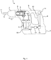
- eine schematische Ansicht einer Handwerkzeugmaschine;
- Fig. 2
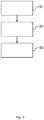
- eine schematische Ansicht eines Steuerungsverfahrens für die Handwerkzeugmaschine gemäß
Fig. 1 ; und - Fig. 3
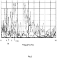
- ein Diagramm eines Frequenzspektrums einer zeitlichen Veränderung einer erfassten Drehbewegung der Handwerkzeugmaschine gemäß
Fig. 1 .
- Fig. 1
- a schematic view of a hand machine tool;
- Fig. 2
- a schematic view of a control method for the handheld power tool according to FIG
Fig. 1 ; and - Fig. 3
- a diagram of a frequency spectrum of a change over time of a detected rotary movement of the handheld power tool according to FIG
Fig. 1 .
Gleiche oder funktionsgleiche Elemente werden durch gleiche Bezugszeichen in den Figuren indiziert, soweit nicht anders angegeben.Identical or functionally identical elements are indicated by the same reference symbols in the figures, unless otherwise stated.
Im Folgenden wird anhand der
Bei einem Bohrvorgang übt der Bohrhammer 1 ein rückwirkendes Drehmoment auf den Benutzer oder den Ständer aus, welches sich als Reaktion auf ein von dem Werkzeug 3 auf ein Werkstück übertragenes Drehmoment ergibt. Im handgehaltenen Betrieb wird dieses rückwirkende Drehmoment auf den Benutzer und im ständer-gehaltenen Betrieb auf den Ständer ausgeübt.During a drilling operation, the
Solange das Werkstück und/oder der Untergrund beim Bohren nachgibt, ist das rückwirkende Drehmoment gering. Im handgehaltenen Betrieb kann der Benutzer diesem geringen rückwirkenden Drehmoment ausreichend entgegenwirken. Die verbleibende Drehbewegung des Gehäuses 9 um die Arbeitsachse 11 nimmt der Benutzer lediglich als ein Rütteln des Gehäuses 9 wahr. Im ständer-gehaltenen Betrieb kann der Ständer einem solchen geringen rückwirkenden Drehmoment noch stärker entgegenwirken, als es der Benutzer könnte. Folglich ist die verbleibende Drehbewegung des Gehäuses 9 um die Arbeitsachse 11 im ständer-gehaltenen Betrieb noch geringer als im handgehaltenen Betrieb.As long as the workpiece and / or the substrate give way during drilling, the retroactive torque is low. In hand-held operation, the user can adequately counteract this small retroactive torque. The user only perceives the remaining rotary movement of the
Bei einem Blockieren des Werkzeugs 3 in dem Werkstück ergibt sich aufgrund des schlagartigen Abbremsens des rotierenden Werkzeugs 3 ein hohes rückwirkendes Drehmoment. Im ständer-gehaltenen Betrieb kann der Ständer diesem hohen rückwirkenden Drehmoment immer noch ausreichend entgegenwirken. Jedoch kann der Benutzer im handgehaltenen Betrieb diesem hohen rückwirkenden Drehmoment nicht mehr ausreichend entgegenwirken, weshalb sich der gesamte Bohrhammer 1 einschließlich des Gehäuses 9 und des Handgriffs 8 um die Drehachse 11 des Werkzeugs 3 zu drehen beginnt.If the
Der Bohrhammer 1 hat eine Schutzeinrichtung 13 zum Reduzieren einer Drehmomentabgabe des Motors 4, die den Benutzer im handgehaltenen Betrieb vor einem übermäßigen rückwirkenden Drehmoment des Werkzeugs 3 schützt. Im ständer-gehaltenen Betrieb des Bohrhammers 1 ist es jedoch wünschenswert, die Schutzeinrichtung 13 abzuschalten.The
In dem Steuerungsverfahren kann der ständer-gehaltene Betrieb von dem handgehaltenen Betrieb des Bohrhammers 1 unterschieden werden, sodass die Schutzeinrichtung 13 im ständer-gehaltenen Betrieb abgeschaltet werden kann.In the control method, the stand-held operation can be distinguished from the hand-held operation of the
In einem ersten Schritt S1 des Steuerungsverfahrens wird die Drehbewegung des Gehäuses 9, insbesondere des Handgriffs 8, des Bohrhammers 1 um die Arbeitsachse 11 erfasst. Dazu weist der Bohrhammer 1 einen Drehbewegungssensor 14 auf. Ein beispielhafter Drehbewegungssensor 14 ist ein Gyrosensor, welcher unmittelbar die Winkelgeschwindigkeit um die Arbeitsachse 11 bestimmt. Der Gyrosensor 14 hat ein schwingend aufgehängtes Plättchen, dessen Schwingungsfrequenz durch die Corioliskraft beeinflusst wird. Der Gyrosensor tastet die Schwingungsfrequenz ab, ermittelt die zugehörige Winkelgeschwindigkeit um die Arbeitsachse 11 und gibt die erfasste Winkelgeschwindigkeit als Messsignal aus. Die Winkelgeschwindigkeit wird von dem Gyrosensor 14 ab dem Betätigen des Haupttasters 10 während des Betriebs des Bohrhammers 1 fortlaufend erfasst. Der Gyrosensor 14 kann nahe der Arbeitsachse 11 oder versetzt zu der Arbeitsachse 11 in dem Gehäuse 9, insbesondere in dem Handgriff 8, angeordnet sein. Der Gyrosensor 14 übermittelt die erfasste Winkelgeschwindigkeit an eine Steuereinrichtung 15 des Bohrhammers 1. Die Steuereinrichtung 15 verarbeitet die erfasste Winkelgeschwindigkeit, insbesondere eine zeitliche Veränderung der erfassten Winkelgeschwindigkeit, um darauf basierend die Schutzfunktion im handgehaltenen Betrieb bei einem zu hohen rückwirkenden Drehmoment auszulösen oder im ständer-gehaltenen Betrieb ganz auszuschalten.In a first step S1 of the control method, the rotary movement of the
In einem zweiten Schritt S2 des Steuerungsverfahrens wird die Schutzfunktion der Schutzeinrichtung 13 zum Reduzieren einer Drehmomentabgabe des Motors 4 ausgelöst, wenn die von dem Gyrosensor 14 erfasste Winkelgeschwindigkeit der Drehung des Gehäuses 9 um die Arbeitsachse 11 einen bestimmten Grenzwert überschreitet. Der bestimmte Grenzwert ist eine bestimmte Winkelgeschwindigkeit, die auf ein Blockieren des Werkzeugs 4 hinweist. In dem Schritt S2 vergleicht die Steuereinrichtung 15 die erfasste Winkelgeschwindigkeit mit dem bestimmten Grenzwert. Wenn die Steuereinrichtung 15 ermittelt, dass die erfasste Winkelgeschwindigkeit den bestimmten Grenzwert überschreitet, sendet die Steuereinrichtung 15 ein entsprechendes Signal an die Schutzeinrichtung 13. Daraufhin löst die Schutzeinrichtung 13 die Schutzfunktion aus. Beispielsweise sendet die Schutzeinrichtung 13 als Schutzfunktion ein Bremssignal an eine Bremse 16 des Motors 4. Der Motor 4 wird dann vorzugsweise bis zum Stillstand abgebremst. Dadurch kann der Benutzer im handgehaltenen Betrieb vor Drehbewegungen des Gehäuses 9 geschützt werden, die er durch Kraftaufwand nicht ausgleichen könnte.In a second step S2 of the control method, the protective function of the
In einem dritten Schritt S3 des Steuerungsverfahrens wird die Schutzfunktion in Abhängigkeit einer charakteristischen Größe eines Frequenzspektrums einer zeitlichen Veränderung der erfassten Drehbewegung um die Arbeitsachse 11 abgeschaltet.In a third step S3 of the control method, the protective function is switched off as a function of a characteristic variable of a frequency spectrum of a temporal change in the detected rotary movement about the working
Zum Erkennen des ständergehaltenen Betriebs des Bohrhammers 1 wird von der Steuereinrichtung 15 ermittelt, ob die von dem Gyrosensor 14 über die Zeit erfasste Winkelgeschwindigkeit auf ein derart geringes rückwirkendes Drehmoment schließen lässt, welches nur in einem ständer-gehaltenen Betrieb auftreten kann. Dazu berechnet die Steuereinrichtung 15 ein Frequenzspektrum der erfassten Winkelgeschwindigkeit. Das Frequenzspektrum wird beispielsweise durch eine Fouriertransformation der von dem Gyrosensor 14 erfassten Winkelgeschwindigkeit in den Frequenzraum bereitgestellt.To detect the operation of the
Zum Unterscheiden des ständer-gehaltenen Betriebs von dem handgehaltenen Betrieb wird in dem dritten Schritt S3 des Verfahrens von der Steuereinrichtung 15 eine charakteristische Größe des Frequenzspektrums ermittelt. Beispielsweise ist die charakteristische Größe des Frequenzspektrums ein Mittelwert der Amplitude eines der Frequenzspektren 17 in
Die Steuereinrichtung 15 vergleicht den für den Frequenzbereich 1,4 bis 1,8 Hz berechneten Mittelwert der Amplitude eines der Frequenzspektren 17 mit dem bestimmten Schwellenwert, um einen handgehaltenen Betrieb des Bohrhammers 1 von einem ständer-gehaltenen Betrieb zu unterscheiden. In
Im Folgenden wird eine Modifikation der anhand der
Im Folgenden wird das Ermitteln der charakteristischen Größe im Falle der Modifikation beschrieben. Zunächst wird ein Frequenzfilter auf die von dem Gyrosensor 14 erfasste zeitliche Veränderung der Winkelgeschwindigkeit oder auf das daraus basierende Spannungssignal, im Folgenden werden beide kurz "Signal" genannt, angewendet. Dazu passiert das Signal einen (elektronischen oder rechner-gestützten) Bandpassfilter mit einem Filterbereich von 1,4 bis 1,8 Hz, um einen zum Erkennen des ständer-gehaltenen Betriebs besonders geeigneten Frequenzbereich von 1,4 bis 1,8 Hz durchzulassen. Des Weiteren kann eine Differenz-Eingangsspannung (Gleichspannungsoffset, DC-Offset) von dem Signal abgezogen werden.The following describes the determination of the characteristic variable in the case of modification. First, a frequency filter is applied to the temporal change in the angular velocity detected by the
Da die erfasste zeitliche Veränderung der Winkelgeschwindigkeit des Gehäuses 9 - und somit auch das Spannungssignal - positive (Beschleunigen) und negative (Abbremsen) Werte aufweist, können durch ein Bilden des Betrages des gefilterten Signals die positiven und negativen Werte gleichgerichtet werden. Das gefilterte und gleichgerichtete Signal passiert einen (elektronischen oder rechner-gestützten) Tiefpassfilter von 0,5 Hz, welcher niedrige Frequenzen von unterhalb 0,5 Hz passieren lässt und höhere Frequenzen abschwächt. Es folgt eine Subtraktion eines konstanten Wertes von dem gleichgerichteten und gefilterten Signal. Dann folgt eine zeitliche Integration mit Hilfe des Algorithmus der Steuereinrichtung 15 oder eines elektronischen Integrators. Die zeitliche Integration wirkt wie ein weiterer Tiefpassfilter, indem sie niedrige Frequenzen durchlässt und hohe Frequenzen abschwächt. Der subtrahierte konstante Wert ist so gewählt, dass die durch das beschriebene wiederholte Frequenzfiltern, Gleichrichten, Integrieren und die Subtraktion erzeugte charakteristische Größe im Falle eines ständer-gehaltenen Betriebs einen negativen Wert hat und im Falle eines handgehaltenen Betriebs einen positiven Wert hat. Dadurch können diese beiden Betriebsarten einfach voneinander unterschieden werden.Since the detected temporal change in the angular velocity of the housing 9 - and thus also the voltage signal - has positive (accelerating) and negative (braking) values, the positive and negative values can be rectified by forming the amount of the filtered signal. The filtered and rectified signal passes an (electronic or computer-aided) low-pass filter of 0.5 Hz, which allows low frequencies below 0.5 Hz to pass and attenuates higher frequencies. A constant value is then subtracted from the rectified and filtered signal. A temporal integration then follows with the aid of the algorithm of the
- 11
- Handwerkzeugmaschine (Bohrhammer)Hand machine tool (hammer drill)
- 22
- WerkzeugaufnahmeTool holder
- 33
- WerkzeugTool
- 44th
- Motorengine
- 55
- SchlagwerkPercussion
- 66th
- Antriebswelledrive shaft
- 77th
- Akkumulatoraccumulator
- 88th
- HandgriffHandle
- 99
- Gehäusecasing
- 1010
- HaupttasterMain button
- 1111
- ArbeitsachseWorking axis
- 1212th
- SchlagrichtungDirection of impact
- 1313th
- SchutzeinrichtungProtective device
- 1414th
- Drehbewegungssensor (Gyrosensor)Rotary motion sensor (gyro sensor)
- 1515th
- SteuereinrichtungControl device
- 1616
- Bremsebrake
- 1717th
- FrequenzspektrumFrequency spectrum
- 1818th
- FrequenzspektrumFrequency spectrum
- 1919th
- bestimmter Schwellenwertcertain threshold
- S1S1
- VerfahrensschrittProcess step
- S2S2
- VerfahrensschrittProcess step
- S3S3
- VerfahrensschrittProcess step
Claims (13)
- Control method for a hand-held power tool (1), which has a tool fitting (2) and a motor (4) for driving the tool fitting (2) in a rotating manner about a working axis (11), comprising the steps of:detecting (S1) a rotating movement of a housing (9) of the hand-held power tool (1) about the working axis (11),triggering (S2) a protective function for reducing a torque output of the motor (4) if the detected rotating movement about the working axis (11) exceeds a specific limit value, andswitching off (S3) the protective function on the basis of a characteristic variable of a frequency spectrum of a detected rotating movement about the working axis (11).
- Control method according to Claim 1, characterized in that the protective function is switched off (S3) if the characteristic variable of the frequency spectrum of the rotating movement about the working axis (11) is below a specific threshold value.
- Control method according to Claim 1 or 2, characterized in that the characteristic variable of the frequency spectrum comprises an amplitude of the frequency spectrum.
- Control method according to one of Claims 1 to 3, characterized in that the characteristic variable of the frequency spectrum comprises a characteristic variable of the frequency spectrum in a frequency range below 20 Hz, preferably below 10 Hz, particularly preferably below 2 Hz.
- Control method according to one of Claims 1 to 4, characterized in that the characteristic variable of the frequency spectrum is based on a temporal integration of the rotating movement.
- Control method according to Claim 5, characterized in that the temporal integration is re-started every time a main switch (10) is actuated.
- Control method according to one of Claims 1 to 6, characterized in that the detection (S1) of the rotating movement comprises detecting an angular velocity.
- Control method according to Claim 7, characterized in that the change over time of the rotating movement comprises an acceleration and deceleration of the angular velocity.
- Control method according to one of Claims 1 to 8, characterized in that the detection (S1) of the rotating movement is carried out by means of a rotating movement sensor (14), in particular a gyro sensor.
- Control method according to one of Claims 1 to 9, characterized in that the protective function activates a brake (16) of the motor (4).
- Hand-held power tool (1) comprising
a tool fitting (2),
a motor (4) for driving the tool fitting (2) in a rotating manner about a working axis (11), a rotating movement sensor (14) for detecting a rotating movement of a housing (9) of the hand-held power tool (1) about the working axis (11),
a protective device (13), which is designed to trigger a protective function for reducing a torque output of the motor (4) if the detected rotating movement about the working axis (11) exceeds a specific limit value, and
a control device (15), which is designed to switch off the protective function on the basis of a characteristic variable of a frequency spectrum of a detected rotating movement about the working axis (11). - Hand-held power tool (1) according to Claim 11, characterized in that the rotating movement sensor (14) is a gyro sensor.
- System comprising a hand-held power tool (1) according to Claim 11 or 12 and a stand for holding the hand-held power tool (1).
Priority Applications (1)
| Application Number | Priority Date | Filing Date | Title |
|---|---|---|---|
| EP18188878.5A EP3610990B1 (en) | 2018-08-14 | 2018-08-14 | Control method for a hand-held machine tool, handheld machine tool and system including the handheld machine tool and a stand |
Applications Claiming Priority (1)
| Application Number | Priority Date | Filing Date | Title |
|---|---|---|---|
| EP18188878.5A EP3610990B1 (en) | 2018-08-14 | 2018-08-14 | Control method for a hand-held machine tool, handheld machine tool and system including the handheld machine tool and a stand |
Publications (2)
| Publication Number | Publication Date |
|---|---|
| EP3610990A1 EP3610990A1 (en) | 2020-02-19 |
| EP3610990B1 true EP3610990B1 (en) | 2021-05-05 |
Family
ID=63254575
Family Applications (1)
| Application Number | Title | Priority Date | Filing Date |
|---|---|---|---|
| EP18188878.5A Active EP3610990B1 (en) | 2018-08-14 | 2018-08-14 | Control method for a hand-held machine tool, handheld machine tool and system including the handheld machine tool and a stand |
Country Status (1)
| Country | Link |
|---|---|
| EP (1) | EP3610990B1 (en) |
Family Cites Families (8)
| Publication number | Priority date | Publication date | Assignee | Title |
|---|---|---|---|---|
| DE19857061C2 (en) | 1998-12-10 | 2000-11-02 | Hilti Ag | Method and device for avoiding accidents in hand-held machine tools due to tool blocking |
| DE10041632A1 (en) | 2000-08-24 | 2002-03-07 | Hilti Ag | Electric hand tool device with safety coupling |
| DE102009045758A1 (en) * | 2009-10-16 | 2011-04-21 | Robert Bosch Gmbh | Hand tool e.g. drilling machine, has processing unit connected with acceleration sensor and electric motor and drive shaft and controlling rotational movement of motor and drive shaft based on acceleration signal |
| DE102013212506A1 (en) * | 2013-06-27 | 2014-12-31 | Robert Bosch Gmbh | Machine tool switching device |
| EP2960021A1 (en) * | 2014-06-27 | 2015-12-30 | HILTI Aktiengesellschaft | Handheld machine tool and control method |
| EP3023202A1 (en) * | 2014-11-20 | 2016-05-25 | HILTI Aktiengesellschaft | Security method and handheld machine tool |
| EP3023203A1 (en) | 2014-11-20 | 2016-05-25 | HILTI Aktiengesellschaft | Control method for a hand-held machine tool |
| DE102015211584A1 (en) * | 2015-06-23 | 2016-12-29 | Robert Bosch Gmbh | Diagnostic device for a hand tool |
-
2018
- 2018-08-14 EP EP18188878.5A patent/EP3610990B1/en active Active
Also Published As
| Publication number | Publication date |
|---|---|
| EP3610990A1 (en) | 2020-02-19 |
Similar Documents
| Publication | Publication Date | Title |
|---|---|---|
| DE19857061C2 (en) | Method and device for avoiding accidents in hand-held machine tools due to tool blocking | |
| DE102013200602B4 (en) | Power tool with improved usability | |
| EP0666148B1 (en) | Method and apparatus for handheld machine tools to prevent accidents caused by blocking of the tool | |
| DE112010001558B4 (en) | Method and apparatus for chatter suppression in work machines | |
| EP1109034B1 (en) | Method and apparatus for investigation and identification of the nature of the underlying surface | |
| DE102004046000B4 (en) | Power tool with a position and orientation system | |
| EP3221089B1 (en) | Security method and handheld machine tool | |
| DE102014219392A1 (en) | Sensor device, in particular hand-held power tool sensor device | |
| DE102010044644A1 (en) | Method for collision detection for a drive unit | |
| WO2013064301A1 (en) | Autonomous implement | |
| EP0638375B1 (en) | Method and device for monitoring chattering in twin drives of tolling stands | |
| EP3023203A1 (en) | Control method for a hand-held machine tool | |
| EP3610990B1 (en) | Control method for a hand-held machine tool, handheld machine tool and system including the handheld machine tool and a stand | |
| WO2011137891A1 (en) | Method for detecting rattling, machine-tool monitoring device, and machine tool | |
| DE10309414A1 (en) | Sensor device for detecting jamming of power tool, especially percussion drill, uses single motion sensor to measure degrees of movement along two sensor axes | |
| DE102019204071A1 (en) | Method for recognizing a first operating state of a handheld power tool | |
| DE102018110623A1 (en) | A STEERING DEVICE BASED ON MAGNETORHEOLOGIC DAMPERS AND METHOD FOR REDUCING STEERING WHEEL PRESSURES AS A RESULT OF WHEEL TRACKS | |
| EP4031331B1 (en) | Method for operating a hand-held power tool, and hand-held power tool | |
| DE102019211303A1 (en) | Method for recognizing the work progress of a hand machine tool | |
| DE102019211305A1 (en) | Method for operating a hand machine tool | |
| DE102020208479A1 (en) | Method for detecting a kickback or a breakdown of a machine tool with an oscillating output movement, device and machine tool with the device | |
| DE102013201289B4 (en) | Method for detecting a swing in a rail vehicle | |
| EP3398725B1 (en) | Oscillating driveable handheld tool and method for operating same | |
| EP3375571A2 (en) | Sensor system for an electric screwdriver for classifying screw processes by means of a magnetic field sensor | |
| DE19716267A1 (en) | Vehicle wheel balancing method |
Legal Events
| Date | Code | Title | Description |
|---|---|---|---|
| PUAI | Public reference made under article 153(3) epc to a published international application that has entered the european phase |
Free format text: ORIGINAL CODE: 0009012 |
|
| STAA | Information on the status of an ep patent application or granted ep patent |
Free format text: STATUS: THE APPLICATION HAS BEEN PUBLISHED |
|
| AK | Designated contracting states |
Kind code of ref document: A1 Designated state(s): AL AT BE BG CH CY CZ DE DK EE ES FI FR GB GR HR HU IE IS IT LI LT LU LV MC MK MT NL NO PL PT RO RS SE SI SK SM TR |
|
| AX | Request for extension of the european patent |
Extension state: BA ME |
|
| STAA | Information on the status of an ep patent application or granted ep patent |
Free format text: STATUS: REQUEST FOR EXAMINATION WAS MADE |
|
| 17P | Request for examination filed |
Effective date: 20200819 |
|
| RBV | Designated contracting states (corrected) |
Designated state(s): AL AT BE BG CH CY CZ DE DK EE ES FI FR GB GR HR HU IE IS IT LI LT LU LV MC MK MT NL NO PL PT RO RS SE SI SK SM TR |
|
| GRAP | Despatch of communication of intention to grant a patent |
Free format text: ORIGINAL CODE: EPIDOSNIGR1 |
|
| STAA | Information on the status of an ep patent application or granted ep patent |
Free format text: STATUS: GRANT OF PATENT IS INTENDED |
|
| INTG | Intention to grant announced |
Effective date: 20210211 |
|
| GRAS | Grant fee paid |
Free format text: ORIGINAL CODE: EPIDOSNIGR3 |
|
| GRAA | (expected) grant |
Free format text: ORIGINAL CODE: 0009210 |
|
| STAA | Information on the status of an ep patent application or granted ep patent |
Free format text: STATUS: THE PATENT HAS BEEN GRANTED |
|
| AK | Designated contracting states |
Kind code of ref document: B1 Designated state(s): AL AT BE BG CH CY CZ DE DK EE ES FI FR GB GR HR HU IE IS IT LI LT LU LV MC MK MT NL NO PL PT RO RS SE SI SK SM TR |
|
| REG | Reference to a national code |
Ref country code: GB Ref legal event code: FG4D Free format text: NOT ENGLISH |
|
| REG | Reference to a national code |
Ref country code: CH Ref legal event code: EP |
|
| REG | Reference to a national code |
Ref country code: AT Ref legal event code: REF Ref document number: 1389219 Country of ref document: AT Kind code of ref document: T Effective date: 20210515 |
|
| REG | Reference to a national code |
Ref country code: IE Ref legal event code: FG4D Free format text: LANGUAGE OF EP DOCUMENT: GERMAN |
|
| REG | Reference to a national code |
Ref country code: DE Ref legal event code: R096 Ref document number: 502018005094 Country of ref document: DE |
|
| REG | Reference to a national code |
Ref country code: LT Ref legal event code: MG9D |
|
| PG25 | Lapsed in a contracting state [announced via postgrant information from national office to epo] |
Ref country code: FI Free format text: LAPSE BECAUSE OF FAILURE TO SUBMIT A TRANSLATION OF THE DESCRIPTION OR TO PAY THE FEE WITHIN THE PRESCRIBED TIME-LIMIT Effective date: 20210505 Ref country code: HR Free format text: LAPSE BECAUSE OF FAILURE TO SUBMIT A TRANSLATION OF THE DESCRIPTION OR TO PAY THE FEE WITHIN THE PRESCRIBED TIME-LIMIT Effective date: 20210505 Ref country code: LT Free format text: LAPSE BECAUSE OF FAILURE TO SUBMIT A TRANSLATION OF THE DESCRIPTION OR TO PAY THE FEE WITHIN THE PRESCRIBED TIME-LIMIT Effective date: 20210505 Ref country code: BG Free format text: LAPSE BECAUSE OF FAILURE TO SUBMIT A TRANSLATION OF THE DESCRIPTION OR TO PAY THE FEE WITHIN THE PRESCRIBED TIME-LIMIT Effective date: 20210805 |
|
| PG25 | Lapsed in a contracting state [announced via postgrant information from national office to epo] |
Ref country code: NO Free format text: LAPSE BECAUSE OF FAILURE TO SUBMIT A TRANSLATION OF THE DESCRIPTION OR TO PAY THE FEE WITHIN THE PRESCRIBED TIME-LIMIT Effective date: 20210805 Ref country code: PL Free format text: LAPSE BECAUSE OF FAILURE TO SUBMIT A TRANSLATION OF THE DESCRIPTION OR TO PAY THE FEE WITHIN THE PRESCRIBED TIME-LIMIT Effective date: 20210505 Ref country code: PT Free format text: LAPSE BECAUSE OF FAILURE TO SUBMIT A TRANSLATION OF THE DESCRIPTION OR TO PAY THE FEE WITHIN THE PRESCRIBED TIME-LIMIT Effective date: 20210906 Ref country code: LV Free format text: LAPSE BECAUSE OF FAILURE TO SUBMIT A TRANSLATION OF THE DESCRIPTION OR TO PAY THE FEE WITHIN THE PRESCRIBED TIME-LIMIT Effective date: 20210505 Ref country code: SE Free format text: LAPSE BECAUSE OF FAILURE TO SUBMIT A TRANSLATION OF THE DESCRIPTION OR TO PAY THE FEE WITHIN THE PRESCRIBED TIME-LIMIT Effective date: 20210505 Ref country code: RS Free format text: LAPSE BECAUSE OF FAILURE TO SUBMIT A TRANSLATION OF THE DESCRIPTION OR TO PAY THE FEE WITHIN THE PRESCRIBED TIME-LIMIT Effective date: 20210505 Ref country code: IS Free format text: LAPSE BECAUSE OF FAILURE TO SUBMIT A TRANSLATION OF THE DESCRIPTION OR TO PAY THE FEE WITHIN THE PRESCRIBED TIME-LIMIT Effective date: 20210905 Ref country code: GR Free format text: LAPSE BECAUSE OF FAILURE TO SUBMIT A TRANSLATION OF THE DESCRIPTION OR TO PAY THE FEE WITHIN THE PRESCRIBED TIME-LIMIT Effective date: 20210806 |
|
| REG | Reference to a national code |
Ref country code: NL Ref legal event code: MP Effective date: 20210505 |
|
| PG25 | Lapsed in a contracting state [announced via postgrant information from national office to epo] |
Ref country code: NL Free format text: LAPSE BECAUSE OF FAILURE TO SUBMIT A TRANSLATION OF THE DESCRIPTION OR TO PAY THE FEE WITHIN THE PRESCRIBED TIME-LIMIT Effective date: 20210505 |
|
| PG25 | Lapsed in a contracting state [announced via postgrant information from national office to epo] |
Ref country code: RO Free format text: LAPSE BECAUSE OF FAILURE TO SUBMIT A TRANSLATION OF THE DESCRIPTION OR TO PAY THE FEE WITHIN THE PRESCRIBED TIME-LIMIT Effective date: 20210505 Ref country code: DK Free format text: LAPSE BECAUSE OF FAILURE TO SUBMIT A TRANSLATION OF THE DESCRIPTION OR TO PAY THE FEE WITHIN THE PRESCRIBED TIME-LIMIT Effective date: 20210505 Ref country code: CZ Free format text: LAPSE BECAUSE OF FAILURE TO SUBMIT A TRANSLATION OF THE DESCRIPTION OR TO PAY THE FEE WITHIN THE PRESCRIBED TIME-LIMIT Effective date: 20210505 Ref country code: SK Free format text: LAPSE BECAUSE OF FAILURE TO SUBMIT A TRANSLATION OF THE DESCRIPTION OR TO PAY THE FEE WITHIN THE PRESCRIBED TIME-LIMIT Effective date: 20210505 Ref country code: SM Free format text: LAPSE BECAUSE OF FAILURE TO SUBMIT A TRANSLATION OF THE DESCRIPTION OR TO PAY THE FEE WITHIN THE PRESCRIBED TIME-LIMIT Effective date: 20210505 Ref country code: EE Free format text: LAPSE BECAUSE OF FAILURE TO SUBMIT A TRANSLATION OF THE DESCRIPTION OR TO PAY THE FEE WITHIN THE PRESCRIBED TIME-LIMIT Effective date: 20210505 Ref country code: ES Free format text: LAPSE BECAUSE OF FAILURE TO SUBMIT A TRANSLATION OF THE DESCRIPTION OR TO PAY THE FEE WITHIN THE PRESCRIBED TIME-LIMIT Effective date: 20210505 |
|
| REG | Reference to a national code |
Ref country code: DE Ref legal event code: R097 Ref document number: 502018005094 Country of ref document: DE |
|
| PLBE | No opposition filed within time limit |
Free format text: ORIGINAL CODE: 0009261 |
|
| STAA | Information on the status of an ep patent application or granted ep patent |
Free format text: STATUS: NO OPPOSITION FILED WITHIN TIME LIMIT |
|
| REG | Reference to a national code |
Ref country code: CH Ref legal event code: PL |
|
| PG25 | Lapsed in a contracting state [announced via postgrant information from national office to epo] |
Ref country code: MC Free format text: LAPSE BECAUSE OF FAILURE TO SUBMIT A TRANSLATION OF THE DESCRIPTION OR TO PAY THE FEE WITHIN THE PRESCRIBED TIME-LIMIT Effective date: 20210505 |
|
| 26N | No opposition filed |
Effective date: 20220208 |
|
| REG | Reference to a national code |
Ref country code: BE Ref legal event code: MM Effective date: 20210831 |
|
| PG25 | Lapsed in a contracting state [announced via postgrant information from national office to epo] |
Ref country code: LI Free format text: LAPSE BECAUSE OF NON-PAYMENT OF DUE FEES Effective date: 20210831 Ref country code: CH Free format text: LAPSE BECAUSE OF NON-PAYMENT OF DUE FEES Effective date: 20210831 |
|
| PG25 | Lapsed in a contracting state [announced via postgrant information from national office to epo] |
Ref country code: IS Free format text: LAPSE BECAUSE OF FAILURE TO SUBMIT A TRANSLATION OF THE DESCRIPTION OR TO PAY THE FEE WITHIN THE PRESCRIBED TIME-LIMIT Effective date: 20210905 Ref country code: LU Free format text: LAPSE BECAUSE OF NON-PAYMENT OF DUE FEES Effective date: 20210814 Ref country code: AL Free format text: LAPSE BECAUSE OF FAILURE TO SUBMIT A TRANSLATION OF THE DESCRIPTION OR TO PAY THE FEE WITHIN THE PRESCRIBED TIME-LIMIT Effective date: 20210505 |
|
| PG25 | Lapsed in a contracting state [announced via postgrant information from national office to epo] |
Ref country code: IT Free format text: LAPSE BECAUSE OF FAILURE TO SUBMIT A TRANSLATION OF THE DESCRIPTION OR TO PAY THE FEE WITHIN THE PRESCRIBED TIME-LIMIT Effective date: 20210505 Ref country code: IE Free format text: LAPSE BECAUSE OF NON-PAYMENT OF DUE FEES Effective date: 20210814 Ref country code: BE Free format text: LAPSE BECAUSE OF NON-PAYMENT OF DUE FEES Effective date: 20210831 |
|
| PG25 | Lapsed in a contracting state [announced via postgrant information from national office to epo] |
Ref country code: CY Free format text: LAPSE BECAUSE OF FAILURE TO SUBMIT A TRANSLATION OF THE DESCRIPTION OR TO PAY THE FEE WITHIN THE PRESCRIBED TIME-LIMIT Effective date: 20210505 |
|
| PG25 | Lapsed in a contracting state [announced via postgrant information from national office to epo] |
Ref country code: HU Free format text: LAPSE BECAUSE OF FAILURE TO SUBMIT A TRANSLATION OF THE DESCRIPTION OR TO PAY THE FEE WITHIN THE PRESCRIBED TIME-LIMIT; INVALID AB INITIO Effective date: 20180814 |
|
| PGFP | Annual fee paid to national office [announced via postgrant information from national office to epo] |
Ref country code: GB Payment date: 20230822 Year of fee payment: 6 |
|
| PGFP | Annual fee paid to national office [announced via postgrant information from national office to epo] |
Ref country code: FR Payment date: 20230828 Year of fee payment: 6 Ref country code: DE Payment date: 20230821 Year of fee payment: 6 |