EP3610984A1 - Workpiece conveyance system and machine tool system - Google Patents
Workpiece conveyance system and machine tool system Download PDFInfo
- Publication number
- EP3610984A1 EP3610984A1 EP18785227.2A EP18785227A EP3610984A1 EP 3610984 A1 EP3610984 A1 EP 3610984A1 EP 18785227 A EP18785227 A EP 18785227A EP 3610984 A1 EP3610984 A1 EP 3610984A1
- Authority
- EP
- European Patent Office
- Prior art keywords
- workpiece
- loader
- relay
- chucks
- main
- Prior art date
- Legal status (The legal status is an assumption and is not a legal conclusion. Google has not performed a legal analysis and makes no representation as to the accuracy of the status listed.)
- Granted
Links
Images













Classifications
-
- B—PERFORMING OPERATIONS; TRANSPORTING
- B23—MACHINE TOOLS; METAL-WORKING NOT OTHERWISE PROVIDED FOR
- B23Q—DETAILS, COMPONENTS, OR ACCESSORIES FOR MACHINE TOOLS, e.g. ARRANGEMENTS FOR COPYING OR CONTROLLING; MACHINE TOOLS IN GENERAL CHARACTERISED BY THE CONSTRUCTION OF PARTICULAR DETAILS OR COMPONENTS; COMBINATIONS OR ASSOCIATIONS OF METAL-WORKING MACHINES, NOT DIRECTED TO A PARTICULAR RESULT
- B23Q7/00—Arrangements for handling work specially combined with or arranged in, or specially adapted for use in connection with, machine tools, e.g. for conveying, loading, positioning, discharging, sorting
- B23Q7/04—Arrangements for handling work specially combined with or arranged in, or specially adapted for use in connection with, machine tools, e.g. for conveying, loading, positioning, discharging, sorting by means of grippers
- B23Q7/048—Multiple gripper units
-
- B—PERFORMING OPERATIONS; TRANSPORTING
- B23—MACHINE TOOLS; METAL-WORKING NOT OTHERWISE PROVIDED FOR
- B23Q—DETAILS, COMPONENTS, OR ACCESSORIES FOR MACHINE TOOLS, e.g. ARRANGEMENTS FOR COPYING OR CONTROLLING; MACHINE TOOLS IN GENERAL CHARACTERISED BY THE CONSTRUCTION OF PARTICULAR DETAILS OR COMPONENTS; COMBINATIONS OR ASSOCIATIONS OF METAL-WORKING MACHINES, NOT DIRECTED TO A PARTICULAR RESULT
- B23Q7/00—Arrangements for handling work specially combined with or arranged in, or specially adapted for use in connection with, machine tools, e.g. for conveying, loading, positioning, discharging, sorting
- B23Q7/04—Arrangements for handling work specially combined with or arranged in, or specially adapted for use in connection with, machine tools, e.g. for conveying, loading, positioning, discharging, sorting by means of grippers
- B23Q7/046—Handling workpieces or tools
-
- B—PERFORMING OPERATIONS; TRANSPORTING
- B23—MACHINE TOOLS; METAL-WORKING NOT OTHERWISE PROVIDED FOR
- B23B—TURNING; BORING
- B23B3/00—General-purpose turning-machines or devices, e.g. centre lathes with feed rod and lead screw; Sets of turning-machines
- B23B3/08—Turning-machines characterised by the use of faceplates
-
- B—PERFORMING OPERATIONS; TRANSPORTING
- B23—MACHINE TOOLS; METAL-WORKING NOT OTHERWISE PROVIDED FOR
- B23B—TURNING; BORING
- B23B3/00—General-purpose turning-machines or devices, e.g. centre lathes with feed rod and lead screw; Sets of turning-machines
- B23B3/30—Turning-machines with two or more working-spindles, e.g. in fixed arrangement
-
- B—PERFORMING OPERATIONS; TRANSPORTING
- B23—MACHINE TOOLS; METAL-WORKING NOT OTHERWISE PROVIDED FOR
- B23Q—DETAILS, COMPONENTS, OR ACCESSORIES FOR MACHINE TOOLS, e.g. ARRANGEMENTS FOR COPYING OR CONTROLLING; MACHINE TOOLS IN GENERAL CHARACTERISED BY THE CONSTRUCTION OF PARTICULAR DETAILS OR COMPONENTS; COMBINATIONS OR ASSOCIATIONS OF METAL-WORKING MACHINES, NOT DIRECTED TO A PARTICULAR RESULT
- B23Q41/00—Combinations or associations of metal-working machines not directed to a particular result according to classes B21, B23, or B24
- B23Q41/02—Features relating to transfer of work between machines
-
- B—PERFORMING OPERATIONS; TRANSPORTING
- B23—MACHINE TOOLS; METAL-WORKING NOT OTHERWISE PROVIDED FOR
- B23Q—DETAILS, COMPONENTS, OR ACCESSORIES FOR MACHINE TOOLS, e.g. ARRANGEMENTS FOR COPYING OR CONTROLLING; MACHINE TOOLS IN GENERAL CHARACTERISED BY THE CONSTRUCTION OF PARTICULAR DETAILS OR COMPONENTS; COMBINATIONS OR ASSOCIATIONS OF METAL-WORKING MACHINES, NOT DIRECTED TO A PARTICULAR RESULT
- B23Q7/00—Arrangements for handling work specially combined with or arranged in, or specially adapted for use in connection with, machine tools, e.g. for conveying, loading, positioning, discharging, sorting
- B23Q7/14—Arrangements for handling work specially combined with or arranged in, or specially adapted for use in connection with, machine tools, e.g. for conveying, loading, positioning, discharging, sorting co-ordinated in production lines
Definitions
- the present invention relates to a workpiece conveyance system and a machine tool system.
- a machine tool such as a lathe includes a workpiece conveyance device that receives and delivers workpieces from/to a plurality of spindles (workpiece holders) that hold and rotate workpieces to be machined.
- a workpiece conveyance device a configuration having main loaders and relay loaders, the main loaders moving along a rail disposed on a machine tool body and receiving and delivering workpieces from/to spindles of the machine tool body and the relay loaders receiving and delivering the workpieces from/to the main loaders and receiving and delivering the workpieces from/to a workpiece supply stand or a workpiece discharge stand, is known (for example, see Patent Literature 1).
- Patent Literature 1 Japanese Patent Registration No. 3474060
- an object of the present invention is to provide a workpiece conveyance system and a machine tool system, by which, even when there are a plurality of workpiece holders such as spindles, it is possible to improve workpiece machining efficiency by efficiently receiving and delivering a workpiece from/to each workpiece holder and shortening a time required for workpiece conveyance.
- the present invention provides a workpiece conveyance system that receives and delivers workpieces from/to n workpiece holders (where n is an integer satisfying n ⁇ 2) that hold and rotate workpieces to be machined, including a main loader including n + m main loader chucks (where m is an integer satisfying m ⁇ 1) that receive and deliver the workpieces from/to the n workpiece holders or n relay loaders disposed corresponding to the n respective workpiece holders to receive and deliver the workpieces from/to the workpiece holders.
- the workpiece conveyance system may include a controller that, when the n main loader chucks hold unmachined workpieces and the m main loader chucks are in an empty state in relation to one of the n workpiece holders, allows the main loader chucks in the empty state to receive a machined workpiece from the one of the workpiece holders and allows the main loader chucks holding the unmachined workpieces to supply the unmachined workpiece to the one of the workpiece holders, and in relation to one of next workpiece holders, allows the main loader chucks previously in the empty state to receive a machined workpiece from the one of the next workpiece holders and allows the main loader chucks holding the unmachined workpieces to supply the unmachined workpiece to the one of the next workpiece holders, the controller receiving the machined workpiece and supplying the unmachined workpiece from/to the one of the workpiece holders repeatedly n times.
- the relay loaders may each include a relay loader chuck that receives and delivers the workpiece from/to the corresponding workpiece holder, and in the main loader, the main loader chucks may move to a position corresponding to the relay loader chuck and receive and deliver the workpiece from/to the relay loader chuck.
- one of the relay loaders may have disposed thereon a plurality of the relay loader chucks.
- the n + m main loader chucks may be disposed in one direction at a predetermined interval
- the relay loader chucks may be disposed at the same interval as that between the main loader chucks
- the relay loader chucks may be disposed in parallel with the one direction with the movement of the relay loaders.
- the workpiece conveyance system may include a controller that performs, in one operation, an operation of delivering the workpieces from the relay loader chucks to the main loader chucks and an operation of delivering the workpieces from the main loader chucks to the relay loader chucks.
- the main loader is movable in a direction that is a horizontal direction and is orthogonal to a direction of a rotation axis of the workpiece holders, and the relay loaders are able to turn in a direction around an axis parallel with the rotation axis of the workpiece holders, and may be configured to turn between a first position where any one of the relay loader chucks faces the workpiece holder and a second position where the relay loader chucks can face the n + m main loader chucks.
- the relay loader chucks and the main loader chucks may be configured to hold the workpieces toward a direction parallel with the rotation axis of the workpiece holders.
- the main loader chucks may be switched between a state of holding a workpiece toward a direction parallel with the rotation axis of the corresponding workpiece holder and a state of holding a workpiece in a downward direction.
- the present invention provides a machine tool system including a machine tool body including a plurality of workpiece holders that hold and rotate workpieces to be machined, a carrying-in part that holds an unmachined workpiece, a carrying-out part that holds a machined workpiece, and the workpiece conveyance system that conveys a workpiece between the workpiece holders and the carrying-in part, or between the workpiece holders and the carrying-out part, or both.
- the main loader since the n + m main loader chucks are provided for the n workpiece holders, the main loader does not need to repeat movement between the workpiece holder and the carrying-in part and between the workpiece holder and the carrying-out part for each workpiece holder, and since the main loader can receive and deliver workpieces from/to the n workpiece holders in a short period of time, the efficiency in conveying workpieces is improved, and thus it is possible to improve workpiece machining efficiency. Furthermore, when the aforementioned controller is provided, receiving of a machined workpiece and supplying of an unmachined workpiece from/to one of the workpiece holders can be efficiently performed by the controller.
- the workpiece conveyance system has the relay loader including the relay loader chucks disposed corresponding to the n respective workpiece holders to receive and deliver workpieces from/to the workpiece holders, and the main loader chuck moves to a position corresponding to the relay loader chuck and receives and delivers a workpiece from/to the relay loader chuck, since the main loader can move toward another workpiece holder while the relay loader delivers and receives a workpiece from/to the workpiece holder, and the time during which the main loader stops is shortened, the efficiency in conveying workpieces can be improved.
- a plurality of workpieces can be simultaneously received and delivered between the plurality of relay loader chucks of such a relay loader and the n + m main loader chucks of the main loader; for example, while a machined workpiece held by one of the relay loader chucks is delivered to one of the main loader chucks, an unmachined workpiece held by another one of the main loader chucks can be received by another one of the relay loader chucks.
- a time required for receiving and delivering the workpieces can be shortened, and efficiency in conveying the workpieces can be improved.
- the relay loader chucks are disposed at the same interval as that among the main loader chucks, and the relay loader chucks can be disposed in parallel with the one direction with the movement of the relay loaders, the relay loader chucks and the n + m main loader chucks can be allowed to easily face each other and a plurality of workpieces can be easily received and delivered.
- the workpiece conveyance system includes a controller that performs, in one operation, an operation of delivering the workpieces from the relay loader chucks to the main loader chucks and an operation of delivering the workpieces from the main loader chucks to the relay loader chucks, the relay loader and the main loader can be easily operated by the controller.
- the main loader when the main loader is movable in a direction that is a horizontal direction and is orthogonal to a direction of a rotation axis of the workpiece holders, and the relay loaders are able to turn in a direction around an axis parallel with the rotation axis of the workpiece holders, and turn between a first position where any one of the relay loader chucks faces the workpiece holder and a second position where the relay loader chucks can face the n + m main loader chucks, the main loader can efficiently move to the workpiece holders and the relay loader turns between the first position and the second position, so that the relay loader chuck can be allowed to easily face the workpiece holder or the main loader chuck.
- the relay loader chuck and the main loader chuck hold workpieces toward a direction parallel with the rotation axis of the workpiece holders, when the relay loader chuck receives and delivers a workpiece from/to the workpiece holder or the main loader chuck, it is possible to shorten a time required for receiving and delivering the workpiece because it is not necessary to change the orientation of the relay loader chuck or the main loader chuck.
- main loader chucks can be switched between a state of holding a workpiece toward a direction parallel with the rotation axis of the corresponding workpiece holder and a state of holding a workpiece in a downward direction, even though the workpiece is placed in an upward direction, it is possible to hold the workpiece by switching the orientation of the main loader chuck and it is possible to ensure the general usability of the orientation in which the workpiece is placed.
- a direction perpendicular to the XZ plane is denoted as a Y direction.
- a direction perpendicular to the XZ plane is denoted as a Y direction.
- the arrow direction is a positive (+) direction and a direction opposite to the arrow direction is a negative (-) direction.
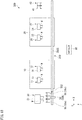
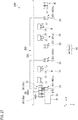
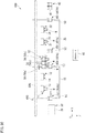
- Fig. 1 is a diagram illustrating an example of a workpiece conveyance system 50 and a machine tool system 100 according to the first embodiment.
- the machine tool system 100 includes a first body (machine tool body) 10, a second body (machine tool body) 20, a carrying-in part 30, a carrying-out part 40, the workpiece conveyance system 50, and a controller 60.
- the controller 60 is a controller of the machine tool system 100 and is a controller of the workpiece conveyance system 50.
- the present invention is not limited to one controller 60 and the controller of the machine tool system 100 and the controller of the workpiece conveyance system 50 may also be installed separately.
- the first body 10 and the second body 20, for example, are parallel double spindle lathes and are disposed in the +Z direction as a front side.
- the first body 10 has spindles (workpiece holders) 11 and 12, and a cutting tool holder such as a turret (not illustrated) that holds a cutting tool.
- the cutting tool holder such as the turret holds a plurality of cutting tools that cut a workpiece W, and one of the cutting tools is selected for use.
- the two spindles 11 and 12 are juxtaposed in the X direction.
- Each of the spindles 11 and 12 is rotatably supported around the axial line of a rotation axis AX1 parallel with the Z direction by a bearing or the like (not illustrated).
- the spindle chucks 13 and 14 are disposed at ends of the spindles 11 and 12 on the +Z side, respectively.
- the spindle chucks 13 and 14 include a plurality of grasping claws 13A and 14A (see Fig. 5 ), and can hold the workpieces W toward the +Z direction by closing the grasping claws 13A and 14A, respectively.
- the second body 20 has spindles (workpiece holders) 21 and 22, and a cutting tool holder such as a turret (not illustrated) that holds a cutting tool.
- the cutting tool holder such as the turret holds a plurality of cutting tools that cut the workpiece W, and one of the cutting tools is selected for use.
- the two spindles 21 and 22 are juxtaposed in the X direction. Each of the spindles 21 and 22 is rotatably supported around the axial line of the rotation axis AX1 parallel with the Z direction by a bearing or the like (not illustrated).
- spindle chucks 23 and 24 are disposed at ends of the spindles 21 and 22 on the +Z side, respectively.
- the spindle chucks 23 and 24 include a plurality of grasping claws 23A and 24A (see Fig. 5 ), and can hold the workpieces W toward the +Z direction by closing the grasping claws 23A and 24A, respectively.
- the spindles 11 and 12 and the spindles 21 and 22 are parallel with each other, the ends of these spindles 11, 12, 21, and 22 on the +Z side are disposed to be aligned in the X direction (spindle chucks 13, 14, 23, and 24 are aligned in the X direction).
- the number of spindles of each of the first body 10 and the second body 20 is 2 but is not limited thereto; n spindles (where n is an integer satisfying n ⁇ 2) may be disposed, and three or more spindles may be disposed.
- the carrying-in part 30 allows an unmachined workpiece W to be machined to be placed thereon in the machine tool system 100.
- the carrying-in part 30 has a holding table 31 that holds the workpieces W.
- the holding table 31 holds two or more (two in the present embodiment) unmachined workpieces W.
- a plurality of workpieces W are juxtaposed at an interval d to be described later.
- the carrying-in part 30 is configured to be able to deliver the unmachined workpiece W to a main loader 52 to be described later. Details of the carrying-in part 30 will be described later.
- the carrying-out part 40 holds a machined workpiece W machined by the first body 10 or the second body 20 in the machine tool system 100.
- the carrying-out part 40 has a plurality of (two in the present embodiment) carrying-out chucks 41 capable of holding the machined workpiece W.
- the carrying-out chucks 41 are juxtaposed at the interval d to be described later.
- Each of the carrying-out chucks 41 can hold the workpiece W toward the -Z direction.
- the carrying-out part 40 is not limited to being provided with the carrying-out chucks 41 and, for example, may include a placement table on which the machined workpiece W is simply placed.
- the workpiece conveyance system 50 has relay loaders 51 (relay loaders) and a main loader 52 (main loader).
- two relay loaders 51 are disposed at two positions of the -X side of the spindle 11 and the +X side of the spindle 12 in the first body 10, and are disposed at two positions of the -X side of the spindle 21 and the +X side of the spindle 22 in the second body 20.
- the relay loaders 51 on the -X side that is, the relay loaders 51 disposed corresponding to the spindles 11 and 21 are denoted as relay loaders 51a.
- the relay loaders 51 on the +X side that is, the relay loaders 51 disposed corresponding to the spindles 12 and 22 are denoted as relay loaders 51b.
- the relay loader 51 has a plurality of (two in the present embodiment) relay loader chucks 53.
- the relay loader chuck 53 on the -X side is denoted as a relay loader chuck 53a and the relay loader chuck 53 on the +X side is denoted as a relay loader chuck 53a.
- the relay loader chucks 53 are disposed at the same interval d as that among a plurality of main loader chucks 56 disposed in the main loader 52 to be described later.
- the number of relay loader chucks 53, which are provided in one relay loader 51, is not limited to 2, and three or more relay loader chucks 53 may be provided. When three or more relay loader chucks 53 are disposed, the respective relay loader chucks 53 are disposed to be aligned in one direction at the predetermined interval d.
- Each of the relay loader chucks 53 includes grasping claws, a sucker, or the like (not illustrated) that hold the workpiece W, and can hold the workpiece W toward the -Z direction, that is, a direction parallel with the rotation axes AX1 of the spindles 11, 12, 21, and 22.
- the relay loader chuck 53 receives and delivers the workpiece W from/to each of the spindles 11, 12, 21, and 22.
- Each of the relay loader chucks 53 can move back and forth in the -Z direction, and when delivering the workpiece W to the spindle 11 or the like, moves in the -Z direction to receive and deliver the workpiece W.
- the present invention is not limited to the case where the relay loader chuck 53 moves back and forth in the -Z direction, and the spindle 11 or the like may move back and forth in the +Z direction when receiving and delivering the workpiece W.
- the relay loader chuck 53 moves in the -Z direction, so that an unmachined workpiece W is delivered from the relay loader chuck 53 to the spindle 11 or the like, or a machined workpiece W is received in the relay loader chuck 53 from the spindle 11 or the like. Details of the relay loader 51 will be described later using other drawings.
- the main loader 52 conveys the workpiece W between the carrying-in part 30 and the relay loader 51 and between the relay loader 51 and the carrying-out part 40.
- the main loader 52 includes a loader head (for example, see a loader head 52B in Fig. 3 ), and the loader head has n + m main loader chucks 56 (where m is an integer satisfying m ⁇ 1).
- main loader chuck 56a the main loader chuck 56 at the center in the X direction is denoted as a main loader chuck 56b
- main loader chuck 56c the main loader chuck 56 on the most +X side is denoted as a main loader chuck 56c.
- Each of the main loader chucks 56 includes a plurality of grasping claws 57 (see Fig. 2 ) that grasp the workpiece W and can hold the workpiece W toward the +Z direction, that is, the direction parallel with the rotation axes AX1 of the spindles 11, 12, 21, and 22 by closing the grasping claws 57.
- the main loader chuck 56 receives the workpiece W from the carrying-in part 30 or delivers the workpiece W to the carrying-out part 40.
- the main loader chuck 56 can move back and forth in the +Z direction.
- the main loader chuck 56 moves in the +Z direction with respect to the carrying-in part 30 or the carrying-out part 40.
- the main loader chuck 56 receives and delivers the workpiece W from/to the relay loader chuck 53.
- the main loader chuck 56 moves in the +Z direction toward the relay loader chuck 53; however, the present invention is not limited thereto and the relay loader chuck 53 may move in the -Z direction toward the main loader chuck 56.
- the main loader chucks 56 may be configured to move back and forth in the +Z direction individually, or to move back and forth in the +Z direction as a whole (for example, together with the loader head). When the main loader chucks 56 move back and forth in the +Z direction as a whole, it is possible to simplify a driving system in the Z direction in the main loader chucks 56.
- the main loader chucks 56 are disposed to be aligned in the X direction at the predetermined interval d. Consequently, the relay loader 51 and the main loader 52 are allowed to face each other in the Z direction, two relay loader chucks 53 and two of the three main loader chucks 56 are brought into a state in which they face each other in a one-to-one manner.
- the main loader 52 has a guide 50G.
- the guide 50G is disposed along the carrying-in part 30, the first body 10, the second body 20, and the carrying-out part 40.
- the main loader chuck 56 is movable along the guide 50G in the X direction (horizontal direction and direction orthogonal to the direction of the rotation axis AX1 of the spindle 11 or the like) together with the loader head (not illustrated) by driving a driving device (not illustrated).
- the main loader chuck 56 moves in the X direction, so that the main loader chuck 56 can be disposed for each of the carrying-in part 30, the first body 10, the second body 20, and the carrying-out part 40.
- a height of the guide 50G is set such that the main loader chuck 56 can receive and deliver the workpiece W at the height thereof.
- the main loader chuck 56 (or the loader head (not illustrated)) can also move vertically, and in such a case, the height of the guide 50G can be arbitrarily set.
- the controller 60 collectively controls the operations of the first body 10, the second body 20, the carrying-in part 30, the carrying-out part 40, and the workpiece conveyance system 50 on the basis of a predetermined machining program.
- the controller 60 includes a communication part (not illustrated), and instructs the operations of the first body 10, the second body 20, the carrying-in part 30, the carrying-out part 40, and the workpiece conveyance system 50 and receives various types of information such as an operation status of each part by the communication part. Communication between the controller 60 and each part may be performed in a wired or wireless manner.
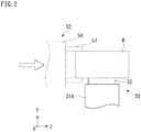
- Fig. 2 is a diagram illustrating an example of the carrying-in part 30.
- the carrying-in part 30 includes a holding table 31A and a conveyor belt 32.
- the conveyor belt 32 can transport the workpiece W by placing the workpiece W on the upper surface thereof.
- the conveyor belt 32 is rotated in the X direction or the Z direction by a driver (not illustrated) in the state in which the workpiece W is placed thereon.
- the workpiece W for example, is placed on the conveyor belt 32 at a position different from the carrying-in part 30, and is disposed on the carrying-in part 30 by the rotation of the conveyor belt 32.
- the workpiece W is placed on the conveyor belt 32, so that the workpieces W can be continuously disposed on the carrying-in part 30 and the arrangement positions of the workpieces W on the carrying-in part 30 can be adjusted.
- the carrying-in part 30 is not limited to being provided with the conveyor belt 32 and may be configured to simply place the workpiece W on the holding table 31A.
- the conveyor belt 32 places the workpiece W in a transverse direction, that is, in a state in which the center axis of the workpiece W is aligned along the Z direction.
- a positioning protrusion or the like may be provided on the conveyor belt 32, for example, such that the workpiece W does not roll on the conveyor belt 32.
- the main loader chuck 56 of the main loader 52 moves in the transverse direction from the - Z side of the workpiece W, and receives the workpiece W by grasping the workpiece W.
- the workpiece W is placed on the conveyor belt 32 with the -Z side of the workpiece W protruding so as not to interfere with the conveyor belt 32 or the holding table 31A when the main loader chuck 56 receives the workpiece W.
- the workpiece W is placed on the carrying-in part 30 in the transverse direction, so that it is possible to receive the workpiece W with the main loader chuck 56 of the main loader 52 directed to the transverse direction (toward the +Z direction) and it is not necessary to provide a structure that changes the orientation of the main loader chuck 56.
- Fig. 3 is a diagram illustrating another example of the main loader.
- the conveyor belt 32 may also place the workpiece W in a longitudinal direction, that is, in a state in which the center axis of the workpiece W is aligned along the Y direction.
- the workpiece W can be placed on the conveyor belt 32 in the longitudinal direction.
- the main loader 52A needs to have a structure that changes the orientation of the main loader chuck 56.
- the main loader 52A includes a switching structure 58 that switches the orientation of the main loader chuck 56.
- the switching structure 58 includes a driver (not illustrated), is provided between the loader head 52B and the main loader chuck 56, and switches the orientation of the main loader chuck 56 between the +Z direction (transverse direction) and the -Y direction (longitudinal direction) by the driver.
- the switching structure 58 includes the driver (not illustrated) and switches the orientation of the main loader chuck 56 by the driver.
- the main loader 52A includes a lifting device (not illustrated) that moves the loader head 52B up and down, and moves the main loader chuck 56 up and down together with the loader head 52B.
- the main loader 52A configured as above sets the main loader chuck 56 downward by the switching structure 58 above the workpiece W placed on the carrying-in part 30, moves down the main loader chuck 56 by the lifting device (not illustrated), and holds the workpiece W by closing the grasping claws 57 at a stage where the grasping claws 57 are positioned outside the upper portion of the workpiece W. Thereafter, the main loader chuck 56 is switched in the transverse direction by the switching structure 58, so that the workpiece W is held toward the +Z direction. As a consequence, it is possible to receive and deliver the workpiece W from/to the relay loader chuck 53 of the relay loader 51.
- Fig. 4 is a diagram illustrating another example of the carrying-in part 30.
- the switching structure 58 is not provided in the main loader 52A illustrated in Fig. 3 , since it is necessary to receive the workpiece W in the transverse direction, the workpiece W, which is placed on the carrying-in part 30 in the longitudinal direction, is changed in the transverse direction, so that it is possible to receive the workpiece W from the carrying-in part 30 by the main loader chuck 56.
- the carrying-in part 30 illustrated in Fig. 4 can switch the workpiece W from the longitudinal direction to the transverse direction.
- the carrying-in part 30 has a holding table 31C and a holding structure 33 that holds the workpiece W.
- the holding structure 33 has a base portion 33a, a shaft portion 33b, and a holding portion 33c.
- the base portion 33a is attached to the holding table 31C; however, instead of this, for example, the base portion 33a may be attached to a conveyor, a rotary table, or the like for movement.
- the shaft portion 33b is disposed in parallel with the X direction on the upper portion of the base portion 33a.
- the holding portion 33c is rotatable in the direction around the axis in the X direction centering on the shaft portion 33b with respect to the base portion 33a, and is rotated by the driver (not illustrated).
- the holding portion 33c includes grasping claws, a sucker, or the like and holds an end portion of the workpiece W.
- the orientation of the workpiece W can be switched between the transverse direction (Z direction) and the longitudinal direction (Y direction).
- the main loader chuck 56 of the main loader 52 can receive the workpiece W in the transverse direction from the +Y side.
- Fig. 5 is a diagram illustrating an example of the relay loader 51, in which (A) illustrates a case where the relay loader 51 is viewed from the +Z direction (front side) and (B) illustrates a case where the relay loader 51 is viewed from the +Y direction (upper side).
- the relay loader 51 has relay loader chucks 53, a shaft 54, and a turning plate 55.
- the relay loader chucks 53 are fixed to the turning plate 55.
- the center axis AX2 of the shaft 54 is disposed in parallel with the Z direction.
- the turning plate 55 can be turned in the direction around the axis of the shaft 54 by the driver (not illustrated).
- Fig. 5 is a diagram illustrating an example of the relay loader 51, in which (A) illustrates a case where the relay loader 51 is viewed from the +Z direction (front side) and (B) illustrates a case where the relay loader 51 is viewed from the +Y direction (upper side).
- the relay loader 51 corresponding to the spindles 11 and 21 is described as an example; however, the same applies to the relay loader 51 corresponding to the spindles 12 and 22 except that it is configured to be symmetrical to the configuration illustrated in Fig. 5 and the turning orientation of the turning plate 55 is opposite.
- the relay loader 51 can move the relay loader chucks 53 between a first position P1 and a second position P2.
- the relay loader chucks 53 face the spindle chucks 13 and 23 of the spindles 11 and 21.
- the relay loader chucks 53 face the main loader chucks 56 of the main loader 52.
- the turning position of the turning plate 55 is adjusted, so that it is possible to allow two relay loader chucks 53a and 53b and the spindles 11 and 21 to face each other at the first position P1.
- (A) in Fig. 5 illustrates a state in which the turning plate 55 indicated by one dot chain line allows the relay loader chuck 53a and the spindles 11 and 21 to face each other at the first position P1.
- the relay loader 51 is provided to be movable back and forth in the -Z direction by the driver (not illustrated).
- the relay loader chuck 53 is movable between a retracted position P1a retracted in the +Z direction in order to prevent the workpiece W from interfering with the spindles 11 and 21 during the turning of the turning plate 55 and an advancing position P1b advanced in the -Z direction in order to be able to receive and deliver the workpiece W from/to the spindles 11 and 21.
- a retracted position P1a retracted in the +Z direction in order to prevent the workpiece W from interfering with the spindles 11 and 21 during the turning of the turning plate 55 and an advancing position P1b advanced in the -Z direction in order to be able to receive and deliver the workpiece W from/to the spindles 11 and 21.
- the relay loader chuck 53 instead of the configuration in which the relay loader chuck 53 is movable back and forth in the -Z direction, it may be possible to employ a configuration in which the spindle chucks 13 and 23 are movable back and forth in the +Z direction.
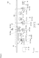
- Fig. 6 to Fig. 10 are diagrams illustrating an example of the operation of the machine tool system 100 including the workpiece conveyance system 50.
- a description will be given for an operation from a state in which workpieces W are machined by a cutting tool T (see (A) in Fig. 5 ) in the spindles 11 and 12 of the first body 10 and the spindles 21 and 22 of the second body 20, and machined workpieces W are held on the relay loader chucks 53b of the relay loader 51 corresponding to the respective spindles 11, 12, 21, and 22.
- a plurality of dots are provided to the machined workpieces W.
- the controller 60 instructs the main loader 52 to receive two workpieces W placed in advance on the carrying-in part 30.
- the two workpieces W are disposed in advance on the carrying-in part 30 in the transverse direction and are set to have the interval d similar to the interval among three main loader chucks 56 or the interval between two relay loader chucks 53.
- the controller 60 moves the three main loader chucks 56 of the main loader 52 in the +Z direction, and allows two main loader chucks 56a and 56b of the three main loader chucks 56 to simultaneously receive the two unmachined workpieces W.
- a main loader chuck 56c moves in the +Z direction together with the other main loader chucks 56a and 56b, but is in an empty state of holding no workpiece W (state of holding no workpiece W, the same applies below).
- the controller 60 moves back the main loader chucks 56 in the -Z direction, then moves the main loader chucks 56 along the guide 50G in the +X direction, and disposes the main loader chucks 56 at a position where the main loader chucks 56 can face the relay loader chucks 53 of the relay loader 51a corresponding to the spindle 11 of the first body 10.
- the controller 60 disposes the relay loader chucks 53 at the second position P2.
- the controller 60 allows the relay loader chuck 53a in the empty state in the relay loader 51a and the main loader chuck 56b holding the unmachined workpiece W in the main loader 52 to face each other. In such a state, the relay loader chuck 53b holding the machined workpiece W in the relay loader 51a and the main loader chuck 56c in the empty state in the main loader 52 are in a state of simultaneously facing each other.
- the controller 60 moves the three main loader chucks 56 in the +Z direction to a position where the workpiece W can be received and delivered from/to the relay loader chucks 53. Subsequently, the controller 60 closes the main loader chuck 56c to hold the machined workpiece W and then releases the relay loader chuck 53b. As a consequence, the machined workpiece W is delivered from the relay loader chuck 53b to the main loader chuck 56c. Simultaneously or almost simultaneously, the controller 60 closes the relay loader chuck 53a to hold the unmachined workpiece W and then releases the main loader chuck 56b.
- the unmachined workpiece W is delivered from the main loader chuck 56b to the relay loader chuck 53a.
- the receiving and delivery of the unmachined workpiece W and the machined workpiece W between the relay loader 51a and the main loader 52 can be simultaneously performed in one operation.
- the relay loader chuck 53a holds the unmachined workpiece W and the relay loader chuck 53b is in an empty state. Furthermore, in the main loader 52, the main loader chuck 56c holds the machined workpiece W and the main loader chuck 56b at the center is in an empty state. The main loader chuck 56a maintains the state of holding the unmachined workpiece W as is.
- the main loader chucks 56 move in the +Z direction; however, instead of this configuration, the relay loader chuck 53 may be allowed to move in the -Z direction.
- the controller 60 performs a series of controls to turn the turning plate 55 (see Fig. 5 ) of the relay loader 51a having received the unmachined workpiece W to the first position P1, to allow the relay loader chuck 53b to receive a machined workpiece W from the spindle chuck 13 (see description of Fig. 8 to be described later), to turn the turning plate 55 by a predetermined amount, to allow the spindle chuck 13 to receive the unmachined workpiece W held by the relay loader chuck 53a (see description of Fig.
- the controller 60 moves back the main loader chucks 56 in the -Z direction, then moves the main loader chucks 56 along the guide 50G in the +X direction, and disposes the main loader chucks 56 at a position where the main loader chucks 56 can face the relay loader chucks 53 of the relay loader 51b corresponding to the spindle 12 of the first body 10.
- the controller 60 disposes the relay loader chucks 53 at the second position P2.
- the controller 60 allows the relay loader chuck 53a in the empty state in the relay loader 51b and the main loader chuck 56a holding the unmachined workpiece W in the main loader 52 to face each other. In such a state, the relay loader chuck 53b holding the machined workpiece W in the relay loader 51a and the main loader chuck 56b in the empty state in the main loader 52 are in a state of simultaneously facing each other.
- the controller 60 moves the three main loader chucks 56 in the +Z direction to a position where the workpiece W can be received from and delivered to the relay loader 51b. Subsequently, the controller 60 closes the main loader chuck 56b to hold the machined workpiece W and then releases the relay loader chuck 53b. As a consequence, the machined workpiece W is delivered from the relay loader chuck 53b to the main loader chuck 56b. Simultaneously or almost simultaneously, the controller 60 closes the relay loader chuck 53a to hold the unmachined workpiece W and then releases the main loader chuck 56a.
- the unmachined workpiece W is delivered from the main loader chuck 56a to the relay loader chuck 53a.
- the receiving and delivery of the unmachined workpiece W and the machined workpiece W between the relay loader 51b and the main loader 52 can be simultaneously performed in one operation.
- the relay loader chuck 53a holds the unmachined workpiece W and the relay loader chuck 53b is in an empty state. Furthermore, in the main loader 52, the main loader chuck 56b holds the machined workpiece W and the main loader chuck 56a is in an empty state. The main loader chuck 56c maintains the state of holding the machined workpiece W as is. Similar to the above description, the receiving and delivery operation of the workpieces W can shorten a time required for receiving delivering the workpieces W.
- the controller 60 moves back the main loader chucks 56 in the -Z direction, then moves the main loader 52 along the guide 50G in the +X direction, and allows the main loader chucks 56 to face the carrying-out chucks 41 of the carrying-out part 40.
- the controller 60 allows the two main loader chucks 56b and 56c holding the machined workpieces W and two carrying-out chucks 41 to face each other.
- An interval between the two carrying-out chucks 41 is set to the interval d, similar to the interval among the main loader chucks 56.
- the controller 60 moves the main loader chucks 56 in the +Z direction to a position where the workpieces W can be received and delivered from/to the carrying-out chucks 41.
- the controller 60 allows each carrying-out chuck 41 to hold the machined workpiece W and releases the main loader chucks 56b and 56c.
- the two machined workpieces W are simultaneously or almost simultaneously delivered from the main loader chucks 56b and 56c to the carrying-out chucks 41, respectively.
- a plurality of (two) workpieces W can be simultaneously received and delivered in one operation.
- the three main loader chucks 56 are in an empty state, move along the guide 50G in the -X direction, and return to the carrying-in part 30, so that two unmachined workpieces W can be held by the main loader chucks 56 as illustrated in Fig. 6 .
- the main loader 52 continuously receives and delivers workpieces W from/to the two relay loaders 51a and 51b disposed in the first body 10. That is, by one-time movement in the +X direction, the main loader 52 conveys two unmachined workpieces W on the carrying-in part 30 to the relay loaders 51a and 51b, respectively, receives machined workpieces W from the relay loaders 51a and 51b, and conveys the machined workpieces W to the carrying-out part 40.
- the main loader chucks 56 hold two unmachined workpieces W on the carrying-in part 30, move along the guide 50G in the +X direction, deliver the unmachined workpiece W to the relay loader chucks 53 of the relay loader 51a corresponding to the spindle 21 of the second body 20, and receive machined workpieces W.
- the receiving and delivery operation of the workpieces W is similar to the operation illustrated in Fig. 7 .
- the main loader chucks 56 move along the guide 50G in the +X direction, deliver unmachined workpieces W to the relay loader chucks 53 of the relay loader 51b corresponding to the spindle 22 of the second body 20, and receive machined workpieces W.
- the receiving and delivery operation of the workpieces W is similar to the operation illustrated in Fig. 9 .
- the main loader chucks 56 move along the guide 50G in the +X direction and deliver the machined workpieces W to the carrying-out chucks 41 of the carrying-out part 40.
- the main loader chucks 56 are in an empty state and return to the carrying-in part 30, so that the main loader chucks 56 can hold two unmachined workpieces W as illustrated in Fig. 6 .
- Such an operation is repeated, so that unmachined workpieces W are continuously supplied to the spindles 11 and 12 of the first body 10 and the spindles 21 and 22 of the second body 20 and machined workpieces W are continuously collected.
- the machined workpieces W held by the carrying-out chucks 41 of the carrying-out part 40 for example, are transported from the carrying-out part 40 to another place by a conveyor device or the like.
- a time required for receiving and delivering the workpieces W is shortened to improve the efficiency in conveying the workpieces W, and thus the efficiency in machining the workpieces W can be improved.
- the number of main loader chucks 56 is 3 (which is equal to the number of spindles (two) plus one); however, the present invention is not limited to this configuration and, for example, four or more main loader chucks 56 may be provided for two spindles because it is sufficient if the number of main loader chucks 56 is the number of spindles plus m.
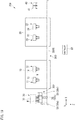
- Fig. 11 is a diagram illustrating an example of a workpiece conveyance system 250 and a machine tool system 200 according to the second embodiment.
- the machine tool system 200 includes the first body (machine tool body) 10, the second body (machine tool body) 20, the carrying-in part 30, the carrying-out part 40, the workpiece conveyance system 250, and the controller 60.
- the configuration of the workpiece conveyance system 250 is different from that of the first embodiment and the other configurations are similar to those of the first embodiment.
- the same or equivalent components as those of the first embodiment are denoted by the same reference numerals and a description thereof will be omitted or simplified.
- the workpiece conveyance system 250 has relay loaders 51 and a main loader 252.
- the relay loader 51 has a configuration similar to that of the first embodiment.
- the number of spindles 11 and 12 of the first body 10 is set to n (which is an integer satisfying n ⁇ 2), but in the second embodiment, the sum of the number of spindles 11 and 12 of the first body 10 and the number of spindles 21 and 22 of the second body 20 is set to n (which is an integer satisfying n ⁇ 2).
- relay loaders 51 disposed in the first body 10 and the second body 20 are distinguished from one another, and a relay loader 51a is disposed corresponding to the spindle 11 of the first body 10, a relay loader 51b is disposed corresponding to the spindle 12 of the first body 10, a relay loader 51c is disposed corresponding to the spindle 21 of the second body 20, and a relay loader 51d is disposed corresponding to the spindle 22 of the second body 20.
- the five main loader chucks 56 are juxtaposed at the interval d in the X direction.
- Each of the main loader chucks 56 has a configuration similar to that of the first embodiment described above.
- main loader chucks 56a, 56b, 56c, 56d, and 56e are sequentially denoted as main loader chucks 56a, 56b, 56c, 56d, and 56e from the -X side to the +X side.
- the carrying-out part 40 has four carrying-out chucks 41 so as to correspond to the main loader chucks 56a to 56e.
- the fact that the carrying-out chucks 41 are juxtaposed at the interval d is similar to that of the first embodiment.
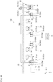
- Fig. 12 to Fig. 14 are diagrams illustrating an example of the operation of the machine tool system 200 including the workpiece conveyance system 250.
- a description will be given for an operation from a state in which workpieces W are machined by the cutting tool T (see (A) in Fig. 5 ) in the spindle 11 and 12 of the first body 10 and the spindle 21 and 22 of the second body 20, and machined workpieces W are held on the relay loader chucks 53b of the relay loaders 51a to 51d corresponding to respective the spindles 11, 12, 21, and 22.
- the controller 60 allows the main loader chucks 56 of the main loader 252 to receive the four unmachined workpieces W placed on the carrying-in part 30.
- the receiving procedure of the workpieces W by each of the main loader chucks 56 is similar to that of the first embodiment.
- the controller 60 allows the four main loader chucks 56a, 56b, 56c, and 56d of the five main loader chucks 56 of the main loader 52 to simultaneously receive the unmachined workpieces W. Consequently, the main loader chuck 56e is in an empty state.
- the controller 60 moves back the main loader chucks 56 in the -Z direction, then moves the main loader chucks 56 along the guide 50G in the +X direction, and disposes the main loader chucks 56 at a position where the main loader chucks 56 can face the relay loader chucks 53 of the relay loader 51a corresponding to the spindle 11 of the first body 10.
- the controller 60 disposes the relay loader chucks 53 at the second position P2.
- the controller 60 allows the relay loader chuck 53a in the empty state in the relay loader 51a and the main loader chuck 56d holding the unmachined workpiece W in the main loader 52 to face each other.
- the relay loader chuck 53b holding the machined workpiece W in the relay loader 51a and the main loader chuck 56e in the empty state in the main loader 52 are in a state of simultaneously facing each other.
- the controller 60 moves the five main loader chucks 56 in the +Z direction to a position where the workpiece W can be received and delivered from/to the relay loader chucks 53. Subsequently, the controller 60 closes the main loader chuck 56e to hold the machined workpiece W and then releases the relay loader chuck 53b. As a consequence, the machined workpiece W is delivered from the relay loader chuck 53b to the main loader chuck 56e. Simultaneously or almost simultaneously, the controller 60 closes the relay loader chuck 53a to hold the unmachined workpiece W and then releases the main loader chuck 56d. As a consequence, the unmachined workpiece W is delivered from the main loader chuck 56d to the relay loader chuck 53a.
- the relay loader chuck 53a holds the unmachined workpiece W and the relay loader chuck 53b is in an empty state. Furthermore, in the main loader 52, the main loader chuck 56e holds the machined workpiece W, the main loader chuck 56d is in an empty state, and the main loader chucks 56a to 56c maintain the state of holding the unmachined workpiece W as is.
- the controller 60 moves back the main loader chucks 56 in the -Z direction, then moves the main loader chucks 56 along the guide 50G in the +X direction, and disposes the main loader chucks 56 at a position where the main loader chucks 56 can face the relay loader chucks 53 of the relay loader 51b corresponding to the spindle 12 of the first body 10.
- the controller 60 disposes the relay loader chucks 53 at the second position P2.
- the controller 60 allows the relay loader chuck 53a in the empty state in the relay loader 51a and the main loader chuck 56c holding the unmachined workpiece W in the main loader 52 to face each other. In such a state, the relay loader chuck 53b holding the machined workpiece W in the relay loader 51b and the main loader chuck 56d in an empty state in the main loader 52 are in a state of simultaneously facing each other.
- the controller 60 moves the five main loader chucks 56 in the +Z direction to a position where the workpiece W can be received from and delivered to the relay loader chucks 53. Subsequently, the controller 60 closes the main loader chuck 56d to hold the machined workpiece W and then releases the relay loader chuck 53b. As a consequence, the machined workpiece W is delivered from the relay loader chuck 53b to the main loader chuck 56d. Simultaneously or almost simultaneously, the controller 60 closes the relay loader chuck 53a to hold the unmachined workpiece W and then releases the main loader chuck 56c. As a consequence, the unmachined workpiece W is delivered from the main loader chuck 56c to the relay loader chuck 53a.
- the relay loader chuck 53a holds the unmachined workpiece W and the relay loader chuck 53b is in an empty state. Furthermore, in the main loader 52, the main loader chucks 56d and 56e hold the machined workpieces W, the main loader chuck 56c is in an empty state, and the main loader chucks 56a and 56b maintain the state of holding the unmachined workpieces W as is.
- the receiving and delivery of the workpieces W between the relay loader chuck 53 and the spindle chuck 13 is similar to the operation of the aforementioned relay loaders 51a illustrated in Fig. 8 and Fig. 9 .
- the controller 60 moves back the main loader chucks 56 in the -Z direction, then moves the main loader chucks 56 along the guide 50G in the +X direction, and disposes the main loader chucks 56 at a position where the main loader chucks 56 can face the relay loader chucks 53 of the relay loader 51c corresponding to the spindle 21 of the second body 20.
- the controller 60 disposes the relay loader chucks 53 at the second position P2.
- the controller 60 allows the relay loader chuck 53a in the empty state in the relay loader 51c and the main loader chuck 56b holding the unmachined workpiece W in the main loader 52 to face each other. In such a state, the relay loader chuck 53b holding the machined workpiece W in the relay loader 51c and the main loader chuck 56c in the empty state in the main loader 52 are in a state of simultaneously facing each other.
- the controller 60 moves the five main loader chucks 56 in the +Z direction to a position where the workpiece W can be received from and delivered to the relay loader chucks 53. Subsequently, the controller 60 closes the main loader chuck 56c to hold the machined workpiece W and then releases the relay loader chuck 53b. As a consequence, the machined workpiece W is delivered from the relay loader chuck 53b to the main loader chuck 56c. Simultaneously or almost simultaneously, the controller 60 closes the relay loader chuck 53a to hold the unmachined workpiece W and then releases the main loader chuck 56b. As a consequence, the unmachined workpiece W is delivered from the main loader chuck 56b to the relay loader chuck 53a.
- the relay loader chuck 53a holds the unmachined workpiece W and the relay loader chuck 53b is in an empty state. Furthermore, in the main loader 52, the main loader chucks 56c to 56e hold the machined workpieces W, the main loader chuck 56b is in an empty state, and the main loader chuck 56a maintains the state of holding the unmachined workpiece W as is.
- the controller 60 moves back the main loader chucks 56 in the -Z direction, then moves the main loader chucks 56 along the guide 50G in the +X direction, and disposes the main loader chucks 56 at a position where the main loader chucks 56 can face the relay loader chucks 53 of the relay loader 51d corresponding to the spindle 22 of the second body 20.
- the controller 60 disposes the relay loader chucks 53 at the second position P2.
- the controller 60 allows the relay loader chuck 53a in the empty state in the relay loader 51d and the main loader chuck 56a holding the unmachined workpiece W in the main loader 52 to face each other. In such a state, the relay loader chuck 53b holding the machined workpiece W in the relay loader 51d and the main loader chuck 56b in the empty state in the main loader 52 are in a state of simultaneously facing each other.
- the controller 60 moves the five main loader chucks 56 in the +Z direction to a position where the workpiece W can be received from and delivered to the relay loader chucks 53. Subsequently, the controller 60 closes the main loader chuck 56c to hold the machined workpiece W and then releases the relay loader chuck 53b. As a consequence, the machined workpiece W is delivered from the relay loader chuck 53b to the main loader chuck 56b. Simultaneously or almost simultaneously, the controller 60 closes the relay loader chuck 53a to hold the unmachined workpiece W and then releases the main loader chuck 56a. As a consequence, the unmachined workpiece W is delivered from the main loader chuck 56a to the relay loader chuck 53a.
- the relay loader chuck 53a holds the unmachined workpiece W and the relay loader chuck 53b is in an empty state. Furthermore, in the main loader 52, the main loader chucks 56b to 56e hold the machined workpieces W and the main loader chuck 56a is in an empty state.
- the controller 60 moves back the main loader chucks 56 in the -Z direction, then moves the main loader chucks 56 along the guide 50G in the +X direction, and disposes the main loader chucks 56 at a position where the main loader chucks 56 can face the carrying-out chucks 41 of the carrying-out part 40.
- the controller 60 moves the five main loader chucks 56 in the +Z direction to a position where the workpieces W can be received from and delivered to the carrying-out chucks 41. Subsequently, the controller 60 allows each carrying-out chuck 41 to hold the machined workpiece W and then releases the main loader chucks 56b to 56e.
- the four machined workpieces W are simultaneously or almost simultaneously delivered from the main loader chucks 56b to 56e to the carrying-out chucks 41, respectively.
- the five main loader chucks 56 are in an empty state, move along the guide 50G in the -X direction, and return to the carrying-in part 30, so that four unmachined workpieces W can be held by the main loader chucks 56 as illustrated in Fig. 12 .
- the main loader 52 continuously receives and delivers workpieces W from/to the four relay loaders 51a to 51d disposed in the first body 10 and the second body 20. That is, by one-time movement in the +X direction, the main loader 52 conveys four unmachined workpieces W on the carrying-in part 30 to the relay loaders 51a to 51d, respectively, receives machined workpieces W from the relay loaders 51a to 51d, and conveys the machined workpieces W to the carrying-out part 40.
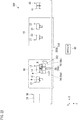
- Fig. 18 is a diagram illustrating an example of a workpiece conveyance system 350 and a machine tool system 300 according to the third embodiment.
- the machine tool system 300 includes the first body (machine tool body) 10, the second body (machine tool body) 20, the carrying-in part 30, the carrying-out part 40, the workpiece conveyance system 350, and the controller 60.
- the configuration of the workpiece conveyance system 350 is different from that of the first embodiment and the other configurations are similar to those of the first embodiment.
- the same or equivalent components as those of the first embodiment are denoted by the same reference numerals and a description thereof will be omitted or simplified.
- the workpiece conveyance system 350 includes a main loader 352 but includes no relay loader.
- n which is the number of spindles 11 and 12 of the first body 10
- the main loader 352 is movable along a guide 350G in the X direction.
- the guide 350G is different from the guide 50G of the first embodiment, and is disposed along the X direction on the +Z side of the first body 10 and the second body 20.
- the main loader chucks 56 have a configuration similar to that illustrated in the first embodiment, except that the main loader chucks 56 are disposed to face the spindle chuck 13 or the like. Similar to the guide 50G of the first embodiment, the guide 350G may be disposed on the -Z side of the first body 10 and the second body 20. In such a case, the main loader 352 is provided with a structure that allows the main loader chucks 56 to face the spindle chuck 13 or the like. Furthermore, the carrying-in part 30 is similar to the first embodiment, except that the carrying-in part 30 holds unmachined workpieces W in the +Z direction.
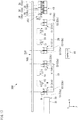
- Fig. 19 to Fig. 24 are diagrams illustrating an example of the operation of the machine tool system 300 including the workpiece conveyance system 350.
- a description will be given for an operation from a state in which workpieces W are machined by the cutting tool T (see (A) in Fig. 5 ) in the spindles 11 and 12 of the first body 10 and the spindles 21 and 22 of the second body 20, and machined workpieces W are held on the spindles 11, 12, 21, and 22, respectively.
- the controller 60 moves the main loader chucks 56 in the -Z direction and allows the main loader chucks 56 of the main loader 352 to receive two unmachined workpiece W placed on the carrying-in part 30.
- the receiving procedure of the workpieces W by each of the main loader chucks 56 is similar to that of the first embodiment.
- the controller 60 allows the two main loader chucks 56a and 56b of the three main loader chucks 56 of the main loader 352 to simultaneously receive the unmachined workpieces W. Consequently, the main loader chuck 56c is in an empty state.
- the controller 60 moves back the main loader chucks 56 in the +Z direction, then moves the main loader chucks 56 along the guide 350G in the +X direction, and disposes the main loader chuck 56c of the main loader chucks 56 at a position where the main loader chuck 56c can face the spindle chuck 13 of the spindle 11.
- the controller 60 moves the three main loader chucks 56 in the -Z direction to a position where the workpiece W can be received from and delivered to the spindle chuck 13.
- the controller 60 closes the main loader chuck 56c to hold the machined workpiece W and then releases the spindle chuck 13. As a consequence, the machined workpiece W is delivered from the spindle chuck 13 to the main loader chuck 56c.
- the controller 60 moves back the main loader chucks 56 in the +Z direction, then moves the main loader chucks 56 along the guide 350G in the +X direction, and then disposes the main loader chuck 56b holding the unmachined workpiece W among the main loader chucks 56 at a position where the main loader chuck 56b can face the spindle chuck 13 of the spindle 11.
- the controller 60 moves the three main loader chucks 56 in the -Z direction to a position where the workpiece W can be received from and delivered to the spindle chuck 13.
- the controller 60 closes the main shaft chuck 13 to hold the unmachined workpiece W and then releases the main loader chuck 56b.
- the unmachined workpiece W is delivered from the main loader chuck 56b to the spindle chuck 13.
- the main loader chuck 56c holds the machined workpiece W
- the main loader chuck 56b is in an empty state
- the main loader chuck 56a maintains the state of holding the unmachined workpiece W as is.
- the controller 60 moves back the main loader chucks 56 in the +Z direction, then moves the main loader chucks 56 along the guide 350G in the +X direction, and disposes the main loader chuck 56b of the main loader chucks 56 at a position where the main loader chuck 56b can face the main spindle 14 of the spindle 12.
- the controller 60 moves the three main loader chucks 56 in the -Z direction to a position where the workpiece W can be received from and delivered to the spindle chuck 14.
- the controller 60 closes the main loader chuck 56b to hold the machined workpiece W and then releases the spindle chuck 14. As a consequence, the machined workpiece W is delivered from the main shaft chuck 14 to the main loader chuck 56b.
- the controller 60 moves back the main loader chucks 56 in the +Z direction, then moves the main loader chucks 56 along the guide 350G in the +X direction, and disposes the main loader chuck 56a holding the unmachined workpiece W among the main loader chucks 56 at a position where the main loader chuck 56a can face the spindle chuck 14 of the spindle 11.
- the controller 60 moves the three main loader chucks 56 in the -Z direction to a position where the workpiece W can be received from and delivered to the spindle chuck 14.
- the controller 60 closes the spindle chuck 14 to hold the unmachined workpiece W and then releases the main loader chuck 56a.
- the unmachined workpiece W is delivered from the main loader chuck 56a to the spindle chuck 14.
- the main loader chucks 56b and 56c hold the machined workpiece W and the main loader chuck 56a is in an empty state.
- the controller 60 moves back the main loader chucks 56 in the +Z direction, then moves the main loader chucks 56 along the guide 350G in the +X direction, and disposes the main loader chucks 56 at a position where the main loader chucks 56 can face the carrying-out chucks 41 of the carrying-out part 40.
- the controller 60 moves back the three main loader chucks 56 in the -Z direction to a position where the workpieces W can be received from and delivered to the carrying-out chucks 41. Subsequently, the controller 60 allows each carrying-out chuck 41 to hold the machined workpiece W and then releases the main loader chucks 56b and 56c. As a consequence, the two machined workpieces W are simultaneously or almost simultaneously delivered from the main loader chucks 56b and 56c to the carrying-out chucks 41, respectively.
- the three main loader chucks 56 are in an empty state, move along the guide 350G in the -X direction, and return to the carrying-in part 30, so that two unmachined workpieces W can be held by the main loader chucks 56 as illustrated in Fig. 19 .
- the main loader 352 continuously receives and delivers workpieces W from/to the two spindle chucks 13 and 14 disposed in the first body 10. That is, by one-time movement in the +X direction, the main loader 352 conveys two unmachined workpieces W on the carrying-in part 30 to the spindle chucks 13 and 14, respectively, receives machined workpieces W from the spindle chucks 13 and 14, and conveys the machined workpieces W to the carrying-out part 40.
- the main loader chucks 356 hold two unmachined workpieces W on the carrying-in part 30, move along the guide 350G in the +X direction, receive a machined workpiece W from the spindle chuck 23 of the spindle 21 of the second body 20, and deliver the unmachined workpiece W.
- the receiving and delivery operation of the workpieces W is similar to the operations in Fig. 20 and Fig. 21 .
- the main loader chucks 56 move along the guide 350G in the +X direction, receive a machined workpiece W from the spindle chuck 24 of the spindle 22 of the second body 20, and deliver the unmachined workpiece W.
- the receiving and delivery operation of the workpieces W is similar to the operations in Fig. 22 and Fig. 23 .
- the main loader chucks 56 move along the guide 350G in the +X direction and deliver the machined workpieces W to the carrying-out chucks 41 of the carrying-out part 40.
- the main loader chucks 56 are in an empty state and return to the carrying-in part 30, so that the main loader chucks 56 can hold two unmachined workpieces W as illustrated in Fig. 19 . Such an operation is repeated, so that unmachined workpieces W are continuously supplied to the spindles 11 and 12 of the first body 10 and the spindles 21 and 22 of the second body 20 and machined workpieces W are continuously collected.
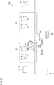
- Fig. 25 is a diagram illustrating an example of a workpiece conveyance system 450 and a machine tool system 400 according to the fourth embodiment.
- the machine tool system 400 includes the first body (machine tool body) 10, the second body (machine tool body) 20, the carrying-in part 30, the carrying-out part 40, the workpiece conveyance system 450, and the controller 60.
- the configuration of the workpiece conveyance system 450 is different from that of the first embodiment and the other configurations are similar to those of the first embodiment.
- the same or equivalent components as those of the first embodiment are denoted by the same reference numerals and a description thereof will be omitted or simplified.
- the workpiece conveyance system 450 has relay loaders 451 and a main loader 52.
- the relay loader 451 one relay loader chuck 53 is provided to the turning plate 55 (see Fig. 5 ). That is, the spindle shaft chuck 13 or the like of the spindle 11 or the like and the relay loader chucks 53 of each relay loader 51 correspond to each other in a one-to-one manner.
- the relay loader 451 can move the relay loader chuck 53 to the first position P1, where the relay loader chuck 53 faces the spindle chuck 13 or the like, and the second position P2, where the relay loader chuck 53 faces the main loader chuck 56 of the main loader 52, by turning the turning plate 55.
- the main loader 52 has a configuration similar to that of the first embodiment.
- Fig. 26 to Fig. 31 are diagrams illustrating an example of the operation of the machine tool system 400 including the workpiece conveyance system 450.
- a description will be given for an operation from a state in which workpieces W are machined by the cutting tool T (see (A) in Fig. 5 ) in the spindles 11 and 12 of the first body 10 and the spindles 21 and 22 of the second body 20, and machined workpieces W are held on the spindles 11, 12, 21, and 22, respectively.
- the controller 60 allows the main loader chucks 56 of the main loader 52 to receive two unmachined workpieces W placed on the carrying-in part 30.
- the receiving procedure of the workpieces W by each of the main loader chucks 56 is similar to that of the first embodiment.
- the controller 60 allows the two main loader chucks 56a and 56b of the three main loader chucks 56 of the main loader 52 to simultaneously receive the unmachined workpieces W. Consequently, the main loader chuck 56c is in an empty state.
- the controller 60 moves back the main loader chucks 56 in the -Z direction, then moves the main loader chucks 56 along the guide 50G in the +X direction, and disposes the main loader chucks 56 at a position where the main loader chucks 56 can face the relay loader chuck 53 of a relay loader 451a corresponding to the spindle 11 of the first body 10.
- the controller 60 disposes the relay loader chuck 53 at the second position P2.
- the controller 60 allows the relay loader chuck 53 of the relay loader 451a and the main loader chuck 56c in the empty state in the main loader 52 to face each other.
- the controller 60 moves the three main loader chucks 56 in the +Z direction to a position where the workpiece W can be received from and delivered to the relay loader chuck 53. Subsequently, the controller 60 closes the main loader chuck 56c to hold the machined workpiece W and then releases the relay loader chuck 53. As a consequence, the machined workpiece W is delivered from the relay loader chuck 53 to the main loader chuck 56c.
- the controller 60 moves back the main loader chucks 56 in the -Z direction, then moves the main loader chucks 56 along the guide 50G in the +X direction, and allows the relay loader chuck 53 of a relay loader 451a and the main loader chuck 56b holding the unmachined workpiece W in the main loader 52 to face each other.
- the controller 60 moves the three main loader chucks 56 in the +Z direction to a position where the workpiece W can be received from and delivered to the relay loader chuck 53. Subsequently, the controller 60 closes the relay loader chuck 53 to hold the unmachined workpiece W and then releases the main loader chuck 56b. As a consequence, the unmachined workpiece W is delivered from the main loader chuck 56b to the relay loader chuck 53.
- the main loader chuck 56c holds the machined workpiece W
- the main loader chuck 56b is in an empty state
- the main loader chuck 56a maintains the state of holding the unmachined workpiece W as is.
- the controller 60 performs a series of controls to turn the turning plate 55 (see Fig. 5 ) of the relay loader 451a having received the unmachined workpiece W to the first position P1, to allow the spindle chuck 13 to receive an unmachined workpiece W held by the relay loader chuck 53 (see description of Fig. 29 to be described later), and to turn the turning plate 55 to the second position P2.
- receiving and delivery of workpieces W between the relay loader chuck 53 and the spindle chuck 13 can also be performed.
- the controller 60 moves back the main loader chucks 56 in the -Z direction, then moves the main loader chucks 56 along the guide 50G in the +X direction, and disposes the main loader chucks 56 at a position where the main loader chucks 56 can face the relay loader chuck 53 of the relay loader 451b corresponding to the spindle 12 of the first body 10.
- the controller 60 disposes the relay loader chuck 53 at the second position P2.
- the controller 60 allows the relay loader chuck 53 holding the machined workpiece W in the relay loader 51b and the main loader chuck 56b in the empty state in the main loader 52 to face each other.
- the controller 60 moves the three main loader chucks 56 in the +Z direction to a position where the workpiece W can be received from and delivered to the relay loader chuck 53. Subsequently, the controller 60 closes the main loader chuck 56b to hold the machined workpiece W and then releases the relay loader chuck 53. As a consequence, the machined workpiece W is delivered from the relay loader chuck 53 to the main loader chuck 56b.
- the controller 60 moves back the main loader chucks 56 in the -Z direction, moves the main loader chucks 56 along the guide 50G in the +X direction, and allows the relay loader chuck 53 of a relay loader 451b and the main loader chuck 56a holding the unmachined workpiece W in the main loader 52 to face each other.
- the controller 60 moves the three main loader chucks 56 in the +Z direction to a position where the workpiece W can be received from and delivered to the relay loader chuck 53. Subsequently, the controller 60 closes the relay loader chuck 53 to hold the unmachined workpiece W and then releases the main loader chuck 56a. As a consequence, the unmachined workpiece W is delivered from the main loader chuck 56a to the relay loader chuck 53. With the aforementioned operation, in the main loader 52, the main loader chucks 56b and 56c hold the machined workpieces W and the main loader chuck 56a is in an empty state.
- the controller 60 moves back the main loader chucks 56 in the -Z direction, then moves the main loader chucks 56 along the guide 50G in the +X direction, and disposes the main loader chucks 56 at a position where the main loader chucks 56 can face the carrying-out chucks 41 of the carrying-out part 40.
- the controller 60 moves the three main loader chucks 56 in the +Z direction to a position where the workpieces W can be received from and delivered to the carrying-out chucks 41. Subsequently, the controller 60 allows each carrying-out chuck 41 to hold the machined workpiece W and then releases the main loader chucks 56b and 56c. As a consequence, the two machined workpieces W are simultaneously or almost simultaneously delivered from the main loader chucks 56b and 56c to the carrying-out chucks 41, respectively.
- the three main loader chucks 56 are in an empty state, move along the guide 50G in the -X direction, and return to the carrying-in part 30, so that two unmachined workpieces W can be held by the main loader chucks 56 as illustrated in Fig. 26 .
- the main loader 52 continuously receives and delivers workpieces W from/to the two spindle chucks 13 and 14 disposed in the first body 10.
- the main loader chucks 56 hold two unmachined workpieces W on the carrying-in part 30, move along the guide 50G in the +X direction, receive a machined workpiece W from the relay loader chuck 53 of the relay loader 451a of the second body 20, and deliver the unmachined workpiece W.
- the receiving and delivery operation of the workpieces W is similar to the operations in Fig. 27 and Fig. 28 .
- the main loader chucks 56 move along the guide 50G in the +X direction, receive a machined workpiece W from the relay loader chuck 53 of the relay loader 451b of the second body 20, and deliver the unmachined workpiece W.
- the receiving and delivery operation of the workpieces W is similar to operations in Fig. 29 and Fig. 30 .
- the main loader chucks 56 move along the guide 50G in the +X direction and deliver the machined workpieces W to the carrying-out chucks 41 of the carrying-out part 40.
- the main loader chucks 56 are in an empty state and return to the carrying-in part 30, so that the main loader chucks 56 can hold two unmachined workpieces W as illustrated in Fig. 26 . Such an operation is repeated, so that unmachined workpieces W are continuously supplied to the spindles 11 and 12 of the first body 10 and the spindles 21 and 22 of the second body 20 and machined workpieces W are continuously collected.
- the present invention is not limited to the aforementioned description and various modifications can be made within the range without departing from the scope of the present invention.
- the components of the aforementioned each embodiment may be appropriately combined.
- the workpiece conveyance system may be configured by replacing a part of the relay loader 51 of the first embodiment with the relay loader 451 of the fourth embodiment.
- the configuration in which the relay loader chucks 53 and the main loader chucks 56 are disposed at the same interval d has been described as an example; however, the present invention is not limited to this configuration and the interval between the relay loader chucks 53 and the interval between the main loader chucks 56 may be different from each other.
- switching between the first position P1 and the second position P2 is performed by turning the turning plate 55 as the relay loaders 51 and 451; however, the present invention is not limited to this configuration.
- the relay loader chuck 53 may also be configured to be slidable in an up and down direction (Y direction) or the like as the relay loaders 51 and 451.
- a lathe has been described as an example of the first body 10 and the second body 20 that are machine tool bodies; however, the machine tool body is not limited to the lathe.
- a machining center or the like may be used as the machine tool body.
- the contents of Japanese Patent Application No. 2017-078246 and all documents cited in the present specification are incorporated herein by reference as a part of the description of the body.
Landscapes
- Engineering & Computer Science (AREA)
- Mechanical Engineering (AREA)
- Turning (AREA)
- Feeding Of Workpieces (AREA)
- Multi-Process Working Machines And Systems (AREA)
Abstract
Description
- The present invention relates to a workpiece conveyance system and a machine tool system.
- A machine tool such as a lathe includes a workpiece conveyance device that receives and delivers workpieces from/to a plurality of spindles (workpiece holders) that hold and rotate workpieces to be machined. As an example of the workpiece conveyance device, a configuration having main loaders and relay loaders, the main loaders moving along a rail disposed on a machine tool body and receiving and delivering workpieces from/to spindles of the machine tool body and the relay loaders receiving and delivering the workpieces from/to the main loaders and receiving and delivering the workpieces from/to a workpiece supply stand or a workpiece discharge stand, is known (for example, see Patent Literature 1).
- [Patent Literature 1] Japanese Patent Registration No.
3474060 - In the aforementioned workpiece conveyance device, since receiving and delivery of the workpiece between the main loader and the relay loader is performed by switching between a chuck receiving the workpiece and a chuck delivering the workpiece, there is a problem in that it takes time to switch between the chucks, and a time required for conveying the workpiece becomes long. Furthermore, for example, in a case where there are a plurality of spindles like a parallel double spindle lathe or the like, if one main loader receives and delivers a workpiece from/to each spindle, a time required for workpiece conveyance becomes long, and workpiece machining efficiency is reduced. Therefore, it is desired to efficiently convey the workpiece when there are a plurality of spindles.
- In view of the foregoing, an object of the present invention is to provide a workpiece conveyance system and a machine tool system, by which, even when there are a plurality of workpiece holders such as spindles, it is possible to improve workpiece machining efficiency by efficiently receiving and delivering a workpiece from/to each workpiece holder and shortening a time required for workpiece conveyance.
- To solve the above problems, the present invention provides a workpiece conveyance system that receives and delivers workpieces from/to n workpiece holders (where n is an integer satisfying n ≥ 2) that hold and rotate workpieces to be machined, including a main loader including n + m main loader chucks (where m is an integer satisfying m ≥ 1) that receive and deliver the workpieces from/to the n workpiece holders or n relay loaders disposed corresponding to the n respective workpiece holders to receive and deliver the workpieces from/to the workpiece holders.
- Furthermore, the workpiece conveyance system may include a controller that, when the n main loader chucks hold unmachined workpieces and the m main loader chucks are in an empty state in relation to one of the n workpiece holders, allows the main loader chucks in the empty state to receive a machined workpiece from the one of the workpiece holders and allows the main loader chucks holding the unmachined workpieces to supply the unmachined workpiece to the one of the workpiece holders, and in relation to one of next workpiece holders, allows the main loader chucks previously in the empty state to receive a machined workpiece from the one of the next workpiece holders and allows the main loader chucks holding the unmachined workpieces to supply the unmachined workpiece to the one of the next workpiece holders, the controller receiving the machined workpiece and supplying the unmachined workpiece from/to the one of the workpiece holders repeatedly n times. Furthermore, the relay loaders may each include a relay loader chuck that receives and delivers the workpiece from/to the corresponding workpiece holder, and in the main loader, the main loader chucks may move to a position corresponding to the relay loader chuck and receive and deliver the workpiece from/to the relay loader chuck. Furthermore, one of the relay loaders may have disposed thereon a plurality of the relay loader chucks. Furthermore, the n + m main loader chucks may be disposed in one direction at a predetermined interval, the relay loader chucks may be disposed at the same interval as that between the main loader chucks, and the relay loader chucks may be disposed in parallel with the one direction with the movement of the relay loaders. Furthermore, the workpiece conveyance system may include a controller that performs, in one operation, an operation of delivering the workpieces from the relay loader chucks to the main loader chucks and an operation of delivering the workpieces from the main loader chucks to the relay loader chucks.
- Furthermore, the main loader is movable in a direction that is a horizontal direction and is orthogonal to a direction of a rotation axis of the workpiece holders, and the relay loaders are able to turn in a direction around an axis parallel with the rotation axis of the workpiece holders, and may be configured to turn between a first position where any one of the relay loader chucks faces the workpiece holder and a second position where the relay loader chucks can face the n + m main loader chucks. Furthermore, the relay loader chucks and the main loader chucks may be configured to hold the workpieces toward a direction parallel with the rotation axis of the workpiece holders. Furthermore, the main loader chucks may be switched between a state of holding a workpiece toward a direction parallel with the rotation axis of the corresponding workpiece holder and a state of holding a workpiece in a downward direction.
- Furthermore, the present invention provides a machine tool system including a machine tool body including a plurality of workpiece holders that hold and rotate workpieces to be machined, a carrying-in part that holds an unmachined workpiece, a carrying-out part that holds a machined workpiece, and the workpiece conveyance system that conveys a workpiece between the workpiece holders and the carrying-in part, or between the workpiece holders and the carrying-out part, or both.
- According to the workpiece conveyance system and the machine tool system of the present invention, since the n + m main loader chucks are provided for the n workpiece holders, the main loader does not need to repeat movement between the workpiece holder and the carrying-in part and between the workpiece holder and the carrying-out part for each workpiece holder, and since the main loader can receive and deliver workpieces from/to the n workpiece holders in a short period of time, the efficiency in conveying workpieces is improved, and thus it is possible to improve workpiece machining efficiency. Furthermore, when the aforementioned controller is provided, receiving of a machined workpiece and supplying of an unmachined workpiece from/to one of the workpiece holders can be efficiently performed by the controller. Furthermore, in the case where the workpiece conveyance system has the relay loader including the relay loader chucks disposed corresponding to the n respective workpiece holders to receive and deliver workpieces from/to the workpiece holders, and the main loader chuck moves to a position corresponding to the relay loader chuck and receives and delivers a workpiece from/to the relay loader chuck, since the main loader can move toward another workpiece holder while the relay loader delivers and receives a workpiece from/to the workpiece holder, and the time during which the main loader stops is shortened, the efficiency in conveying workpieces can be improved. Furthermore, when one of relay loaders has disposed thereon a plurality of the relay loader chucks, a plurality of workpieces can be simultaneously received and delivered between the plurality of relay loader chucks of such a relay loader and the n + m main loader chucks of the main loader; for example, while a machined workpiece held by one of the relay loader chucks is delivered to one of the main loader chucks, an unmachined workpiece held by another one of the main loader chucks can be received by another one of the relay loader chucks. As described above, since a plurality of workpieces can be simultaneously received and delivered, a time required for receiving and delivering the workpieces can be shortened, and efficiency in conveying the workpieces can be improved.
- Furthermore, when the n + m main loader chucks are disposed in one direction at a predetermined interval, the relay loader chucks are disposed at the same interval as that among the main loader chucks, and the relay loader chucks can be disposed in parallel with the one direction with the movement of the relay loaders, the relay loader chucks and the n + m main loader chucks can be allowed to easily face each other and a plurality of workpieces can be easily received and delivered. Furthermore, when the workpiece conveyance system includes a controller that performs, in one operation, an operation of delivering the workpieces from the relay loader chucks to the main loader chucks and an operation of delivering the workpieces from the main loader chucks to the relay loader chucks, the relay loader and the main loader can be easily operated by the controller. Furthermore, when the main loader is movable in a direction that is a horizontal direction and is orthogonal to a direction of a rotation axis of the workpiece holders, and the relay loaders are able to turn in a direction around an axis parallel with the rotation axis of the workpiece holders, and turn between a first position where any one of the relay loader chucks faces the workpiece holder and a second position where the relay loader chucks can face the n + m main loader chucks, the main loader can efficiently move to the workpiece holders and the relay loader turns between the first position and the second position, so that the relay loader chuck can be allowed to easily face the workpiece holder or the main loader chuck.
- Furthermore, in a case where the relay loader chuck and the main loader chuck hold workpieces toward a direction parallel with the rotation axis of the workpiece holders, when the relay loader chuck receives and delivers a workpiece from/to the workpiece holder or the main loader chuck, it is possible to shorten a time required for receiving and delivering the workpiece because it is not necessary to change the orientation of the relay loader chuck or the main loader chuck. Furthermore, when the main loader chucks can be switched between a state of holding a workpiece toward a direction parallel with the rotation axis of the corresponding workpiece holder and a state of holding a workpiece in a downward direction, even though the workpiece is placed in an upward direction, it is possible to hold the workpiece by switching the orientation of the main loader chuck and it is possible to ensure the general usability of the orientation in which the workpiece is placed.
-
-
Fig. 1 is a diagram illustrating an example of a workpiece conveyance system and a machine tool system according to a first embodiment. -
Fig. 2 is a diagram illustrating an example of a carrying-in part. -
Fig. 3 is a diagram illustrating another example of a main loader. -
Fig. 4 is a diagram illustrating another example of a carrying-in part. -
Fig. 5 illustrates an example of a relay loader, in which (A) is a diagram viewed from a +Z direction and (B) is a diagram viewed from a +Y direction. -
Fig. 6 is a diagram illustrating an example of an operation of the workpiece conveyance system. -
Fig. 7 is a diagram illustrating an example of an operation of the workpiece conveyance system, subsequently toFig. 6 . -
Fig. 8 is a diagram illustrating an example of an operation of the workpiece conveyance system, subsequently toFig. 7 . -
Fig. 9 is a diagram illustrating an example of an operation of the workpiece conveyance system, subsequently toFig. 8 . -
Fig. 10 is a diagram illustrating an example of an operation of the workpiece conveyance system, subsequently toFig. 9 . -
Fig. 11 is a diagram illustrating an example of a workpiece conveyance system and a machine tool system according to a second embodiment. -
Fig. 12 is a diagram illustrating an example of an operation of the workpiece conveyance system, subsequently toFig. 11 . -
Fig. 13 is a diagram illustrating an example of an operation of the workpiece conveyance system, subsequently toFig. 12 . -
Fig. 14 is a diagram illustrating an example of an operation of the workpiece conveyance system, subsequently toFig. 13 . -
Fig. 15 is a diagram illustrating an example of an operation of the workpiece conveyance system, subsequently toFig. 14 . -
Fig. 16 is a diagram illustrating an example of an operation of the workpiece conveyance system, subsequently toFig. 15 . -
Fig. 17 is a diagram illustrating an example of an operation of the workpiece conveyance system, subsequently toFig. 16 . -
Fig. 18 is a diagram illustrating an example of a workpiece conveyance system and a machine tool system according to a third embodiment. -
Fig. 19 is a diagram illustrating an example of an operation of the workpiece conveyance system, subsequently toFig. 18 . -
Fig. 20 is a diagram illustrating an example of an operation of the workpiece conveyance system, subsequently toFig. 19 . -
Fig. 21 is a diagram illustrating an example of an operation of the workpiece conveyance system, subsequently toFig. 20 . -
Fig. 22 is a diagram illustrating an example of an operation of the workpiece conveyance system, subsequently toFig. 21 . -
Fig. 23 is a diagram illustrating an example of an operation of the workpiece conveyance system, subsequently toFig. 22 . -
Fig. 24 is a diagram illustrating an example of an operation of the workpiece conveyance system, subsequently toFig. 23 . -
Fig. 25 is a diagram illustrating an example of a workpiece conveyance system and a machine tool system according to a fourth embodiment. -
Fig. 26 is a diagram illustrating an example of an operation of the workpiece conveyance system, subsequently toFig. 25 . -
Fig. 27 is a diagram illustrating an example of an operation of the workpiece conveyance system, subsequently toFig. 26 . -
Fig. 28 is a diagram illustrating an example of an operation of the workpiece conveyance system, subsequently toFig. 27 . -
Fig. 29 is a diagram illustrating an example of an operation of the workpiece conveyance system, subsequently toFig. 28 . -
Fig. 30 is a diagram illustrating an example of an operation of the workpiece conveyance system, subsequently toFig. 29 . -
Fig. 31 is a diagram illustrating an example of an operation of the workpiece conveyance system, subsequently toFig. 30 . - Hereinafter, embodiments of the present invention will be described with reference to the drawings. However, the present invention is not limited to the forms illustrated in the drawings. In the drawings, in order to describe the content, the scale is appropriately changed by enlarging or emphasizing a part, for example. In each of the following drawings, directions in the drawings will be described using an XYZ coordinate system. In the XYZ coordinate system, a plane parallel with a horizontal plane is defined as an XZ plane. In the XZ plane, a direction of a
spindle 11 or the like is denoted as a Z direction and a direction orthogonal to the Z direction is denoted as an X direction. Furthermore, a direction perpendicular to the XZ plane is denoted as a Y direction. Each of the X direction, the Y direction, and the Z direction will be described on the assumption that in the drawings, the arrow direction is a positive (+) direction and a direction opposite to the arrow direction is a negative (-) direction. - A first embodiment will be described with reference to the drawings.
Fig. 1 is a diagram illustrating an example of aworkpiece conveyance system 50 and amachine tool system 100 according to the first embodiment. As illustrated inFig. 1 , themachine tool system 100 includes a first body (machine tool body) 10, a second body (machine tool body) 20, a carrying-inpart 30, a carrying-outpart 40, theworkpiece conveyance system 50, and acontroller 60. Thecontroller 60 is a controller of themachine tool system 100 and is a controller of theworkpiece conveyance system 50. However, the present invention is not limited to onecontroller 60 and the controller of themachine tool system 100 and the controller of theworkpiece conveyance system 50 may also be installed separately. - The
first body 10 and thesecond body 20, for example, are parallel double spindle lathes and are disposed in the +Z direction as a front side. Thefirst body 10 has spindles (workpiece holders) 11 and 12, and a cutting tool holder such as a turret (not illustrated) that holds a cutting tool. The cutting tool holder such as the turret holds a plurality of cutting tools that cut a workpiece W, and one of the cutting tools is selected for use. The twospindles spindles spindles claws Fig. 5 ), and can hold the workpieces W toward the +Z direction by closing the graspingclaws - Similar to the
first body 10, thesecond body 20 has spindles (workpiece holders) 21 and 22, and a cutting tool holder such as a turret (not illustrated) that holds a cutting tool. The cutting tool holder such as the turret holds a plurality of cutting tools that cut the workpiece W, and one of the cutting tools is selected for use. The twospindles spindles spindles spindles claws Fig. 5 ), and can hold the workpieces W toward the +Z direction by closing the graspingclaws - The
spindles spindles spindles first body 10 and thesecond body 20 is 2 but is not limited thereto; n spindles (where n is an integer satisfying n ≥ 2) may be disposed, and three or more spindles may be disposed. - The carrying-in
part 30 allows an unmachined workpiece W to be machined to be placed thereon in themachine tool system 100. The carrying-inpart 30 has a holding table 31 that holds the workpieces W. The holding table 31 holds two or more (two in the present embodiment) unmachined workpieces W. A plurality of workpieces W are juxtaposed at an interval d to be described later. The carrying-inpart 30 is configured to be able to deliver the unmachined workpiece W to amain loader 52 to be described later. Details of the carrying-inpart 30 will be described later. - The carrying-out
part 40 holds a machined workpiece W machined by thefirst body 10 or thesecond body 20 in themachine tool system 100. The carrying-outpart 40 has a plurality of (two in the present embodiment) carrying-outchucks 41 capable of holding the machined workpiece W. The carrying-outchucks 41 are juxtaposed at the interval d to be described later. Each of the carrying-outchucks 41 can hold the workpiece W toward the -Z direction. However, the carrying-outpart 40 is not limited to being provided with the carrying-outchucks 41 and, for example, may include a placement table on which the machined workpiece W is simply placed. - The
workpiece conveyance system 50 has relay loaders 51 (relay loaders) and a main loader 52 (main loader). Therelay loaders 51 are disposed corresponding to nrespective spindles respective spindles relay loaders 51 are disposed at two positions of the -X side of thespindle 11 and the +X side of thespindle 12 in thefirst body 10, and are disposed at two positions of the -X side of thespindle 21 and the +X side of thespindle 22 in thesecond body 20. Hereinafter, when the tworelay loaders 51 disposed in each of thefirst body 10 and thesecond body 20 are distinguished from each other, therelay loaders 51 on the -X side, that is, therelay loaders 51 disposed corresponding to thespindles relay loaders 51a. Furthermore, therelay loaders 51 on the +X side, that is, therelay loaders 51 disposed corresponding to thespindles relay loaders 51b. - The
relay loader 51 has a plurality of (two in the present embodiment) relay loader chucks 53. Hereinafter, when the two relay loader chucks 53 are distinguished from each other, therelay loader chuck 53 on the -X side is denoted as arelay loader chuck 53a and therelay loader chuck 53 on the +X side is denoted as arelay loader chuck 53a. The relay loader chucks 53 are disposed at the same interval d as that among a plurality of main loader chucks 56 disposed in themain loader 52 to be described later. - The number of relay loader chucks 53, which are provided in one
relay loader 51, is not limited to 2, and three or more relay loader chucks 53 may be provided. When three or more relay loader chucks 53 are disposed, the respective relay loader chucks 53 are disposed to be aligned in one direction at the predetermined interval d. Each of the relay loader chucks 53 includes grasping claws, a sucker, or the like (not illustrated) that hold the workpiece W, and can hold the workpiece W toward the -Z direction, that is, a direction parallel with the rotation axes AX1 of thespindles relay loader chuck 53 receives and delivers the workpiece W from/to each of thespindles - Each of the relay loader chucks 53 can move back and forth in the -Z direction, and when delivering the workpiece W to the
spindle 11 or the like, moves in the -Z direction to receive and deliver the workpiece W. However, the present invention is not limited to the case where therelay loader chuck 53 moves back and forth in the -Z direction, and thespindle 11 or the like may move back and forth in the +Z direction when receiving and delivering the workpiece W. Therelay loader chuck 53 moves in the -Z direction, so that an unmachined workpiece W is delivered from therelay loader chuck 53 to thespindle 11 or the like, or a machined workpiece W is received in therelay loader chuck 53 from thespindle 11 or the like. Details of therelay loader 51 will be described later using other drawings. - The
main loader 52 conveys the workpiece W between the carrying-inpart 30 and therelay loader 51 and between therelay loader 51 and the carrying-outpart 40. Themain loader 52 includes a loader head (for example, see aloader head 52B inFig. 3 ), and the loader head has n + m main loader chucks 56 (where m is an integer satisfying m ≥ 1). In the present embodiment, a case where the number of main loader chucks 56 is 3, that is, n = 2 and m = 1 will be described. Hereinafter, when three main loader chucks 56 are distinguished from one another, themain loader chuck 56 on the most -X side is denoted as amain loader chuck 56a, themain loader chuck 56 at the center in the X direction is denoted as amain loader chuck 56b, and themain loader chuck 56 on the most +X side is denoted as amain loader chuck 56c. - Each of the main loader chucks 56 includes a plurality of grasping claws 57 (see
Fig. 2 ) that grasp the workpiece W and can hold the workpiece W toward the +Z direction, that is, the direction parallel with the rotation axes AX1 of thespindles claws 57. Themain loader chuck 56 receives the workpiece W from the carrying-inpart 30 or delivers the workpiece W to the carrying-outpart 40. Themain loader chuck 56 can move back and forth in the +Z direction. When receiving the workpiece W from the carrying-inpart 30 or when delivering the workpiece W to the carrying-outpart 40, themain loader chuck 56 moves in the +Z direction with respect to the carrying-inpart 30 or the carrying-outpart 40. - Furthermore, the
main loader chuck 56 receives and delivers the workpiece W from/to therelay loader chuck 53. When receiving and delivering the workpiece W, themain loader chuck 56 moves in the +Z direction toward therelay loader chuck 53; however, the present invention is not limited thereto and therelay loader chuck 53 may move in the -Z direction toward themain loader chuck 56. The main loader chucks 56 may be configured to move back and forth in the +Z direction individually, or to move back and forth in the +Z direction as a whole (for example, together with the loader head). When the main loader chucks 56 move back and forth in the +Z direction as a whole, it is possible to simplify a driving system in the Z direction in the main loader chucks 56. - The main loader chucks 56, for example, are disposed to be aligned in the X direction at the predetermined interval d. Consequently, the
relay loader 51 and themain loader 52 are allowed to face each other in the Z direction, two relay loader chucks 53 and two of the three main loader chucks 56 are brought into a state in which they face each other in a one-to-one manner. - The
main loader 52 has aguide 50G. Theguide 50G is disposed along the carrying-inpart 30, thefirst body 10, thesecond body 20, and the carrying-outpart 40. Themain loader chuck 56 is movable along theguide 50G in the X direction (horizontal direction and direction orthogonal to the direction of the rotation axis AX1 of thespindle 11 or the like) together with the loader head (not illustrated) by driving a driving device (not illustrated). Themain loader chuck 56 moves in the X direction, so that themain loader chuck 56 can be disposed for each of the carrying-inpart 30, thefirst body 10, thesecond body 20, and the carrying-outpart 40. Furthermore, when themain loader chuck 56 is disposed for the carrying-inpart 30 or the like, a height of theguide 50G is set such that themain loader chuck 56 can receive and deliver the workpiece W at the height thereof. However, the main loader chuck 56 (or the loader head (not illustrated)) can also move vertically, and in such a case, the height of theguide 50G can be arbitrarily set. - The
controller 60 collectively controls the operations of thefirst body 10, thesecond body 20, the carrying-inpart 30, the carrying-outpart 40, and theworkpiece conveyance system 50 on the basis of a predetermined machining program. Thecontroller 60 includes a communication part (not illustrated), and instructs the operations of thefirst body 10, thesecond body 20, the carrying-inpart 30, the carrying-outpart 40, and theworkpiece conveyance system 50 and receives various types of information such as an operation status of each part by the communication part. Communication between thecontroller 60 and each part may be performed in a wired or wireless manner. -
Fig. 2 is a diagram illustrating an example of the carrying-inpart 30. As illustrated inFig. 2 , the carrying-inpart 30 includes a holding table 31A and aconveyor belt 32. Theconveyor belt 32 can transport the workpiece W by placing the workpiece W on the upper surface thereof. Theconveyor belt 32 is rotated in the X direction or the Z direction by a driver (not illustrated) in the state in which the workpiece W is placed thereon. The workpiece W, for example, is placed on theconveyor belt 32 at a position different from the carrying-inpart 30, and is disposed on the carrying-inpart 30 by the rotation of theconveyor belt 32. As described above, the workpiece W is placed on theconveyor belt 32, so that the workpieces W can be continuously disposed on the carrying-inpart 30 and the arrangement positions of the workpieces W on the carrying-inpart 30 can be adjusted. The carrying-inpart 30 is not limited to being provided with theconveyor belt 32 and may be configured to simply place the workpiece W on the holding table 31A. - As illustrated in
Fig. 2 , theconveyor belt 32 places the workpiece W in a transverse direction, that is, in a state in which the center axis of the workpiece W is aligned along the Z direction. When the workpiece W is placed in the transverse direction, a positioning protrusion or the like may be provided on theconveyor belt 32, for example, such that the workpiece W does not roll on theconveyor belt 32. When the workpiece W is placed in the transverse direction, themain loader chuck 56 of themain loader 52 moves in the transverse direction from the - Z side of the workpiece W, and receives the workpiece W by grasping the workpiece W. Furthermore, the workpiece W is placed on theconveyor belt 32 with the -Z side of the workpiece W protruding so as not to interfere with theconveyor belt 32 or the holding table 31A when themain loader chuck 56 receives the workpiece W. As described above, the workpiece W is placed on the carrying-inpart 30 in the transverse direction, so that it is possible to receive the workpiece W with themain loader chuck 56 of themain loader 52 directed to the transverse direction (toward the +Z direction) and it is not necessary to provide a structure that changes the orientation of themain loader chuck 56. -
Fig. 3 is a diagram illustrating another example of the main loader. As illustrated inFig. 3 , theconveyor belt 32 may also place the workpiece W in a longitudinal direction, that is, in a state in which the center axis of the workpiece W is aligned along the Y direction. When an end surface of the workpiece W is a flat surface, the workpiece W can be placed on theconveyor belt 32 in the longitudinal direction. When the workpiece W is placed in the longitudinal direction, it is necessary to move themain loader chuck 56 of amain loader 52A toward the +Y direction (that is, the longitudinal direction) from the upper side to the lower side of the workpiece W. However, when the workpiece W is received and delivered from/to another part other than the carrying-inpart 30, since themain loader chuck 56 needs to direct the workpiece W toward the +Z direction (that is, the transverse direction), themain loader 52A needs to have a structure that changes the orientation of themain loader chuck 56. - As illustrated in
Fig. 3 , themain loader 52A includes a switchingstructure 58 that switches the orientation of themain loader chuck 56. The switchingstructure 58 includes a driver (not illustrated), is provided between theloader head 52B and themain loader chuck 56, and switches the orientation of themain loader chuck 56 between the +Z direction (transverse direction) and the -Y direction (longitudinal direction) by the driver. The switchingstructure 58 includes the driver (not illustrated) and switches the orientation of themain loader chuck 56 by the driver. Furthermore, themain loader 52A includes a lifting device (not illustrated) that moves theloader head 52B up and down, and moves themain loader chuck 56 up and down together with theloader head 52B. - The
main loader 52A configured as above sets themain loader chuck 56 downward by the switchingstructure 58 above the workpiece W placed on the carrying-inpart 30, moves down themain loader chuck 56 by the lifting device (not illustrated), and holds the workpiece W by closing the graspingclaws 57 at a stage where the graspingclaws 57 are positioned outside the upper portion of the workpiece W. Thereafter, themain loader chuck 56 is switched in the transverse direction by the switchingstructure 58, so that the workpiece W is held toward the +Z direction. As a consequence, it is possible to receive and deliver the workpiece W from/to therelay loader chuck 53 of therelay loader 51. -
Fig. 4 is a diagram illustrating another example of the carrying-inpart 30. When the switchingstructure 58 is not provided in themain loader 52A illustrated inFig. 3 , since it is necessary to receive the workpiece W in the transverse direction, the workpiece W, which is placed on the carrying-inpart 30 in the longitudinal direction, is changed in the transverse direction, so that it is possible to receive the workpiece W from the carrying-inpart 30 by themain loader chuck 56. The carrying-inpart 30 illustrated inFig. 4 can switch the workpiece W from the longitudinal direction to the transverse direction. As illustrated inFig. 4 , the carrying-inpart 30 has a holding table 31C and a holding structure 33 that holds the workpiece W. The holding structure 33 has abase portion 33a, ashaft portion 33b, and a holdingportion 33c. Thebase portion 33a is attached to the holding table 31C; however, instead of this, for example, thebase portion 33a may be attached to a conveyor, a rotary table, or the like for movement. Theshaft portion 33b is disposed in parallel with the X direction on the upper portion of thebase portion 33a. - The holding
portion 33c is rotatable in the direction around the axis in the X direction centering on theshaft portion 33b with respect to thebase portion 33a, and is rotated by the driver (not illustrated). The holdingportion 33c includes grasping claws, a sucker, or the like and holds an end portion of the workpiece W. When the holdingportion 33c moves in the direction around the axis of theshaft portion 33b, the orientation of the workpiece W can be switched between the transverse direction (Z direction) and the longitudinal direction (Y direction). Consequently, for example, in a state in which the workpiece W has been transported to the carrying-inpart 30, even though the workpiece W is directed in the longitudinal direction, when the workpiece W is delivered to themain loader 52, it is possible to dispose the workpiece W from the longitudinal direction to the transverse direction by rotating the holdingportion 33c. As a consequence, themain loader chuck 56 of themain loader 52 can receive the workpiece W in the transverse direction from the +Y side. -
Fig. 5 is a diagram illustrating an example of therelay loader 51, in which (A) illustrates a case where therelay loader 51 is viewed from the +Z direction (front side) and (B) illustrates a case where therelay loader 51 is viewed from the +Y direction (upper side). As illustrated inFig. 5 , therelay loader 51 has relay loader chucks 53, ashaft 54, and a turningplate 55. The relay loader chucks 53 are fixed to the turningplate 55. The center axis AX2 of theshaft 54 is disposed in parallel with the Z direction. The turningplate 55 can be turned in the direction around the axis of theshaft 54 by the driver (not illustrated). InFig. 5 , therelay loader 51 corresponding to thespindles relay loader 51 corresponding to thespindles Fig. 5 and the turning orientation of the turningplate 55 is opposite. - When the turning
plate 55 is turned in the direction around the axis of theshaft 54, therelay loader 51 can move the relay loader chucks 53 between a first position P1 and a second position P2. When the turningplate 55 is at the first position P1, the relay loader chucks 53 face the spindle chucks 13 and 23 of thespindles plate 55 is at the second position P2, the relay loader chucks 53 face the main loader chucks 56 of themain loader 52. - In the
relay loader 51, the turning position of the turningplate 55 is adjusted, so that it is possible to allow two relay loader chucks 53a and 53b and thespindles Fig. 5 illustrates a state in which theturning plate 55 indicated by one dot chain line allows therelay loader chuck 53a and thespindles Fig. 5 , therelay loader 51 is provided to be movable back and forth in the -Z direction by the driver (not illustrated). Therelay loader chuck 53 is movable between a retracted position P1a retracted in the +Z direction in order to prevent the workpiece W from interfering with thespindles plate 55 and an advancing position P1b advanced in the -Z direction in order to be able to receive and deliver the workpiece W from/to thespindles relay loader chuck 53 is movable back and forth in the -Z direction, it may be possible to employ a configuration in which the spindle chucks 13 and 23 are movable back and forth in the +Z direction. - Subsequently, the operation of the
workpiece conveyance system 50 and themachine tool system 100 configured as described above will be described.Fig. 6 to Fig. 10 are diagrams illustrating an example of the operation of themachine tool system 100 including theworkpiece conveyance system 50. In the following example, a description will be given for an operation from a state in which workpieces W are machined by a cutting tool T (see (A) inFig. 5 ) in thespindles first body 10 and thespindles second body 20, and machined workpieces W are held on the relay loader chucks 53b of therelay loader 51 corresponding to therespective spindles - As illustrated in
Fig. 6 , thecontroller 60 instructs themain loader 52 to receive two workpieces W placed in advance on the carrying-inpart 30. The two workpieces W are disposed in advance on the carrying-inpart 30 in the transverse direction and are set to have the interval d similar to the interval among three main loader chucks 56 or the interval between two relay loader chucks 53. Thecontroller 60 moves the three main loader chucks 56 of themain loader 52 in the +Z direction, and allows two main loader chucks 56a and 56b of the three main loader chucks 56 to simultaneously receive the two unmachined workpieces W. In such a case, amain loader chuck 56c moves in the +Z direction together with the other main loader chucks 56a and 56b, but is in an empty state of holding no workpiece W (state of holding no workpiece W, the same applies below). - Next, the
controller 60 moves back the main loader chucks 56 in the -Z direction, then moves the main loader chucks 56 along theguide 50G in the +X direction, and disposes the main loader chucks 56 at a position where the main loader chucks 56 can face the relay loader chucks 53 of therelay loader 51a corresponding to thespindle 11 of thefirst body 10. After or before the main loader chucks 56 are reached, in a state in which therelay loader chuck 53b of therelay loader 51a holds the machined workpiece W received from thespindle 11 and therelay loader chuck 53a is empty, thecontroller 60 disposes the relay loader chucks 53 at the second position P2. Thecontroller 60 allows therelay loader chuck 53a in the empty state in therelay loader 51a and themain loader chuck 56b holding the unmachined workpiece W in themain loader 52 to face each other. In such a state, therelay loader chuck 53b holding the machined workpiece W in therelay loader 51a and themain loader chuck 56c in the empty state in themain loader 52 are in a state of simultaneously facing each other. - Next, as illustrated in
Fig. 7 , thecontroller 60 moves the three main loader chucks 56 in the +Z direction to a position where the workpiece W can be received and delivered from/to the relay loader chucks 53. Subsequently, thecontroller 60 closes themain loader chuck 56c to hold the machined workpiece W and then releases therelay loader chuck 53b. As a consequence, the machined workpiece W is delivered from therelay loader chuck 53b to themain loader chuck 56c. Simultaneously or almost simultaneously, thecontroller 60 closes therelay loader chuck 53a to hold the unmachined workpiece W and then releases themain loader chuck 56b. As a consequence, the unmachined workpiece W is delivered from themain loader chuck 56b to therelay loader chuck 53a. As described above, the receiving and delivery of the unmachined workpiece W and the machined workpiece W between therelay loader 51a and themain loader 52 can be simultaneously performed in one operation. - With the aforementioned operation, in the
relay loader 51a, therelay loader chuck 53a holds the unmachined workpiece W and therelay loader chuck 53b is in an empty state. Furthermore, in themain loader 52, themain loader chuck 56c holds the machined workpiece W and themain loader chuck 56b at the center is in an empty state. Themain loader chuck 56a maintains the state of holding the unmachined workpiece W as is. In the receiving and delivery operation of the workpieces W, since it is not necessary to change the orientation of therelay loader chuck 53 or themain loader chuck 56 for the receiving and delivery of the workpieces W, and the receiving and delivery of the workpieces W are performed in one operation, it is possible to shorten a time required for receiving and delivering the workpieces W. In the above, the main loader chucks 56 move in the +Z direction; however, instead of this configuration, therelay loader chuck 53 may be allowed to move in the -Z direction. - In addition, during the conveyance of the workpiece W by the
main loader 52 and the receiving and delivery of the workpiece W from/to thenext relay loader 51b, thecontroller 60 performs a series of controls to turn the turning plate 55 (seeFig. 5 ) of therelay loader 51a having received the unmachined workpiece W to the first position P1, to allow therelay loader chuck 53b to receive a machined workpiece W from the spindle chuck 13 (see description ofFig. 8 to be described later), to turn the turningplate 55 by a predetermined amount, to allow thespindle chuck 13 to receive the unmachined workpiece W held by therelay loader chuck 53a (see description ofFig. 9 to be described later), to turn the turningplate 55 to the second position P2 in the state in which therelay loader chuck 53b holds the machined workpiece W (see description ofFig. 10 to be described later), and to allow therelay loader 51a to reach the state illustrated inFig. 6 . In a manner similar to the receiving delivery of the workpieces W between therelay loader chuck 53 and thespindle chuck 13, receiving and delivery of workpieces W between anotherrelay loader chuck 53 and another main shaft chuck, 14, or the like, can also be performed. - Next, as illustrated in
Fig. 8 , thecontroller 60 moves back the main loader chucks 56 in the -Z direction, then moves the main loader chucks 56 along theguide 50G in the +X direction, and disposes the main loader chucks 56 at a position where the main loader chucks 56 can face the relay loader chucks 53 of therelay loader 51b corresponding to thespindle 12 of thefirst body 10. After or before the main loader chucks 56 are reached, in a state in which therelay loader chuck 53b of therelay loader 51b holds a machined workpiece W received from thespindle 12 and therelay loader chuck 53a is empty, thecontroller 60 disposes the relay loader chucks 53 at the second position P2. Thecontroller 60 allows therelay loader chuck 53a in the empty state in therelay loader 51b and themain loader chuck 56a holding the unmachined workpiece W in themain loader 52 to face each other. In such a state, therelay loader chuck 53b holding the machined workpiece W in therelay loader 51a and themain loader chuck 56b in the empty state in themain loader 52 are in a state of simultaneously facing each other. - Next, as illustrated in
Fig. 9 , thecontroller 60 moves the three main loader chucks 56 in the +Z direction to a position where the workpiece W can be received from and delivered to therelay loader 51b. Subsequently, thecontroller 60 closes themain loader chuck 56b to hold the machined workpiece W and then releases therelay loader chuck 53b. As a consequence, the machined workpiece W is delivered from therelay loader chuck 53b to themain loader chuck 56b. Simultaneously or almost simultaneously, thecontroller 60 closes therelay loader chuck 53a to hold the unmachined workpiece W and then releases themain loader chuck 56a. As a consequence, the unmachined workpiece W is delivered from themain loader chuck 56a to therelay loader chuck 53a. As described above, the receiving and delivery of the unmachined workpiece W and the machined workpiece W between therelay loader 51b and themain loader 52 can be simultaneously performed in one operation. - With the aforementioned operation, in the
relay loader 51b, therelay loader chuck 53a holds the unmachined workpiece W and therelay loader chuck 53b is in an empty state. Furthermore, in themain loader 52, themain loader chuck 56b holds the machined workpiece W and themain loader chuck 56a is in an empty state. Themain loader chuck 56c maintains the state of holding the machined workpiece W as is. Similar to the above description, the receiving and delivery operation of the workpieces W can shorten a time required for receiving delivering the workpieces W. - Next, the
controller 60 moves back the main loader chucks 56 in the -Z direction, then moves themain loader 52 along theguide 50G in the +X direction, and allows the main loader chucks 56 to face the carrying-outchucks 41 of the carrying-outpart 40. In such a case, thecontroller 60 allows the two main loader chucks 56b and 56c holding the machined workpieces W and two carrying-outchucks 41 to face each other. An interval between the two carrying-out chucks 41 is set to the interval d, similar to the interval among the main loader chucks 56. Subsequently, as illustrated inFig. 10 , thecontroller 60 moves the main loader chucks 56 in the +Z direction to a position where the workpieces W can be received and delivered from/to the carrying-outchucks 41. - Subsequently, the
controller 60 allows each carrying-out chuck 41 to hold the machined workpiece W and releases the main loader chucks 56b and 56c. As a consequence, the two machined workpieces W are simultaneously or almost simultaneously delivered from the main loader chucks 56b and 56c to the carrying-out chucks 41, respectively. As described above, between themain loader 52 and the carrying-outpart 40, a plurality of (two) workpieces W can be simultaneously received and delivered in one operation. With such an operation, in themain loader 52, the three main loader chucks 56 are in an empty state, move along theguide 50G in the -X direction, and return to the carrying-inpart 30, so that two unmachined workpieces W can be held by the main loader chucks 56 as illustrated inFig. 6 . - As described above, while the
main loader 52 moves once in the +X direction from the carrying-inpart 30 to the carrying-outpart 40, themain loader 52 continuously receives and delivers workpieces W from/to the tworelay loaders first body 10. That is, by one-time movement in the +X direction, themain loader 52 conveys two unmachined workpieces W on the carrying-inpart 30 to therelay loaders relay loaders part 40. - Next, in a manner similar to the illustration in
Fig. 6 , the main loader chucks 56 hold two unmachined workpieces W on the carrying-inpart 30, move along theguide 50G in the +X direction, deliver the unmachined workpiece W to the relay loader chucks 53 of therelay loader 51a corresponding to thespindle 21 of thesecond body 20, and receive machined workpieces W. The receiving and delivery operation of the workpieces W is similar to the operation illustrated inFig. 7 . Next, in a manner similar to the illustration inFig. 8 , the main loader chucks 56 move along theguide 50G in the +X direction, deliver unmachined workpieces W to the relay loader chucks 53 of therelay loader 51b corresponding to thespindle 22 of thesecond body 20, and receive machined workpieces W. The receiving and delivery operation of the workpieces W is similar to the operation illustrated inFig. 9 . Next, the main loader chucks 56 move along theguide 50G in the +X direction and deliver the machined workpieces W to the carrying-outchucks 41 of the carrying-outpart 40. - In the
main loader 52, the main loader chucks 56 are in an empty state and return to the carrying-inpart 30, so that the main loader chucks 56 can hold two unmachined workpieces W as illustrated inFig. 6 . Such an operation is repeated, so that unmachined workpieces W are continuously supplied to thespindles first body 10 and thespindles second body 20 and machined workpieces W are continuously collected. The machined workpieces W held by the carrying-outchucks 41 of the carrying-outpart 40, for example, are transported from the carrying-outpart 40 to another place by a conveyor device or the like. In the present embodiment, the receiving and delivery operation of the workpieces W by the main loader chucks 56 is repeated twice (n = 2) for thespindles spindles - As described above, according to the present embodiment, since a plurality of the workpieces W can be simultaneously delivered and received, and the
main loader 52 does not frequently reciprocate between themain loader 52 and the carrying-inpart 30 or between themain loader 52 and the carrying-outpart 40, a time required for receiving and delivering the workpieces W is shortened to improve the efficiency in conveying the workpieces W, and thus the efficiency in machining the workpieces W can be improved. In the aforementioned embodiment, an example corresponding to thefirst body 10 and thesecond body 20 each having two spindles has been described; however, even though each body has three or more spindles, (the number of spindles + m) main loader chucks 56 are disposed, so that it is possible to cope with the situation in a manner similar to the above description. Furthermore, it would be similar to the above even though there are one or three or more bodies each having two spindles. Furthermore, the number of main loader chucks 56 is 3 (which is equal to the number of spindles (two) plus one); however, the present invention is not limited to this configuration and, for example, four or more main loader chucks 56 may be provided for two spindles because it is sufficient if the number of main loader chucks 56 is the number of spindles plus m. - A second embodiment will be described with reference to the drawings.
Fig. 11 is a diagram illustrating an example of aworkpiece conveyance system 250 and amachine tool system 200 according to the second embodiment. As illustrated inFig. 11 , themachine tool system 200 includes the first body (machine tool body) 10, the second body (machine tool body) 20, the carrying-inpart 30, the carrying-outpart 40, theworkpiece conveyance system 250, and thecontroller 60. In the second embodiment, the configuration of theworkpiece conveyance system 250 is different from that of the first embodiment and the other configurations are similar to those of the first embodiment. In the following description, the same or equivalent components as those of the first embodiment are denoted by the same reference numerals and a description thereof will be omitted or simplified. - The
workpiece conveyance system 250 hasrelay loaders 51 and amain loader 252. Therelay loader 51 has a configuration similar to that of the first embodiment. In the first embodiment, the number ofspindles first body 10 is set to n (which is an integer satisfying n ≥ 2), but in the second embodiment, the sum of the number ofspindles first body 10 and the number ofspindles second body 20 is set to n (which is an integer satisfying n ≥ 2). Consequently, in the present embodiment, fourrelay loaders 51 disposed in thefirst body 10 and thesecond body 20 are distinguished from one another, and arelay loader 51a is disposed corresponding to thespindle 11 of thefirst body 10, arelay loader 51b is disposed corresponding to thespindle 12 of thefirst body 10, arelay loader 51c is disposed corresponding to thespindle 21 of thesecond body 20, and arelay loader 51d is disposed corresponding to thespindle 22 of thesecond body 20. - Furthermore, in the present embodiment, the
main loader 252 has five main loader chucks 56 of n + 1 (m = 1). The five main loader chucks 56 are juxtaposed at the interval d in the X direction. Each of the main loader chucks 56 has a configuration similar to that of the first embodiment described above. Hereinafter, when the five main loader chucks 56 are distinguished from one another, they are sequentially denoted as main loader chucks 56a, 56b, 56c, 56d, and 56e from the -X side to the +X side. - On the carrying-in
part 30, four unmachined workpieces W are placed in parallel to correspond to the main loader chucks 56a to 56e. The fact that the four workpieces W are disposed at the interval d is similar to that of the first embodiment. Furthermore, the carrying-outpart 40 has four carrying-outchucks 41 so as to correspond to the main loader chucks 56a to 56e. The fact that the carrying-outchucks 41 are juxtaposed at the interval d is similar to that of the first embodiment. - Subsequently, the operation of the
workpiece conveyance system 250 and themachine tool system 200 configured as described above will be described.Fig. 12 to Fig. 14 are diagrams illustrating an example of the operation of themachine tool system 200 including theworkpiece conveyance system 250. In the following example, as in the first embodiment, a description will be given for an operation from a state in which workpieces W are machined by the cutting tool T (see (A) inFig. 5 ) in thespindle first body 10 and thespindle second body 20, and machined workpieces W are held on the relay loader chucks 53b of therelay loaders 51a to 51d corresponding to respective thespindles - As illustrated in
Fig. 12 , thecontroller 60 allows the main loader chucks 56 of themain loader 252 to receive the four unmachined workpieces W placed on the carrying-inpart 30. The receiving procedure of the workpieces W by each of the main loader chucks 56 is similar to that of the first embodiment. Thecontroller 60 allows the four main loader chucks 56a, 56b, 56c, and 56d of the five main loader chucks 56 of themain loader 52 to simultaneously receive the unmachined workpieces W. Consequently, themain loader chuck 56e is in an empty state. - Next, the
controller 60 moves back the main loader chucks 56 in the -Z direction, then moves the main loader chucks 56 along theguide 50G in the +X direction, and disposes the main loader chucks 56 at a position where the main loader chucks 56 can face the relay loader chucks 53 of therelay loader 51a corresponding to thespindle 11 of thefirst body 10. As in the first embodiment, after or before the main loader chucks 56 are reached, in a state in which therelay loader chuck 53b of therelay loader 51a holds the machined workpiece W received from thespindle 11 and therelay loader chuck 53a is empty, thecontroller 60 disposes the relay loader chucks 53 at the second position P2. Thecontroller 60 allows therelay loader chuck 53a in the empty state in therelay loader 51a and themain loader chuck 56d holding the unmachined workpiece W in themain loader 52 to face each other. In such a state, therelay loader chuck 53b holding the machined workpiece W in therelay loader 51a and themain loader chuck 56e in the empty state in themain loader 52 are in a state of simultaneously facing each other. - Next, as illustrated in
Fig. 13 , thecontroller 60 moves the five main loader chucks 56 in the +Z direction to a position where the workpiece W can be received and delivered from/to the relay loader chucks 53. Subsequently, thecontroller 60 closes themain loader chuck 56e to hold the machined workpiece W and then releases therelay loader chuck 53b. As a consequence, the machined workpiece W is delivered from therelay loader chuck 53b to themain loader chuck 56e. Simultaneously or almost simultaneously, thecontroller 60 closes therelay loader chuck 53a to hold the unmachined workpiece W and then releases themain loader chuck 56d. As a consequence, the unmachined workpiece W is delivered from themain loader chuck 56d to therelay loader chuck 53a. - With the aforementioned operation, in the
relay loader 51a, therelay loader chuck 53a holds the unmachined workpiece W and therelay loader chuck 53b is in an empty state. Furthermore, in themain loader 52, themain loader chuck 56e holds the machined workpiece W, themain loader chuck 56d is in an empty state, and the main loader chucks 56a to 56c maintain the state of holding the unmachined workpiece W as is. - Next, the
controller 60 moves back the main loader chucks 56 in the -Z direction, then moves the main loader chucks 56 along theguide 50G in the +X direction, and disposes the main loader chucks 56 at a position where the main loader chucks 56 can face the relay loader chucks 53 of therelay loader 51b corresponding to thespindle 12 of thefirst body 10. In a manner similar to the first embodiment, after or before the main loader chucks 56 are reached, in a state in which therelay loader chuck 53b of therelay loader 51b holds the machined workpiece W received from thespindle 12 and therelay loader chuck 53a is empty, thecontroller 60 disposes the relay loader chucks 53 at the second position P2. Thecontroller 60 allows therelay loader chuck 53a in the empty state in therelay loader 51a and themain loader chuck 56c holding the unmachined workpiece W in themain loader 52 to face each other. In such a state, therelay loader chuck 53b holding the machined workpiece W in therelay loader 51b and themain loader chuck 56d in an empty state in themain loader 52 are in a state of simultaneously facing each other. - Next, as illustrated in
Fig. 14 , thecontroller 60 moves the five main loader chucks 56 in the +Z direction to a position where the workpiece W can be received from and delivered to the relay loader chucks 53. Subsequently, thecontroller 60 closes themain loader chuck 56d to hold the machined workpiece W and then releases therelay loader chuck 53b. As a consequence, the machined workpiece W is delivered from therelay loader chuck 53b to themain loader chuck 56d. Simultaneously or almost simultaneously, thecontroller 60 closes therelay loader chuck 53a to hold the unmachined workpiece W and then releases themain loader chuck 56c. As a consequence, the unmachined workpiece W is delivered from themain loader chuck 56c to therelay loader chuck 53a. - With the aforementioned operation, in the
relay loader 51b, therelay loader chuck 53a holds the unmachined workpiece W and therelay loader chuck 53b is in an empty state. Furthermore, in themain loader 52, the main loader chucks 56d and 56e hold the machined workpieces W, themain loader chuck 56c is in an empty state, and the main loader chucks 56a and 56b maintain the state of holding the unmachined workpieces W as is. Although not illustrated in the second embodiment, the receiving and delivery of the workpieces W between therelay loader chuck 53 and thespindle chuck 13 is similar to the operation of theaforementioned relay loaders 51a illustrated inFig. 8 andFig. 9 . - Next, the
controller 60 moves back the main loader chucks 56 in the -Z direction, then moves the main loader chucks 56 along theguide 50G in the +X direction, and disposes the main loader chucks 56 at a position where the main loader chucks 56 can face the relay loader chucks 53 of therelay loader 51c corresponding to thespindle 21 of thesecond body 20. In a manner similar to the first embodiment, after or before the main loader chucks 56 are reached, in a state in which therelay loader chuck 53b of therelay loader 51c holds the machined workpiece W received from thespindle 12 and therelay loader chuck 53a is empty, thecontroller 60 disposes the relay loader chucks 53 at the second position P2. Thecontroller 60 allows therelay loader chuck 53a in the empty state in therelay loader 51c and themain loader chuck 56b holding the unmachined workpiece W in themain loader 52 to face each other. In such a state, therelay loader chuck 53b holding the machined workpiece W in therelay loader 51c and themain loader chuck 56c in the empty state in themain loader 52 are in a state of simultaneously facing each other. - Next, as illustrated in
Fig. 15 , thecontroller 60 moves the five main loader chucks 56 in the +Z direction to a position where the workpiece W can be received from and delivered to the relay loader chucks 53. Subsequently, thecontroller 60 closes themain loader chuck 56c to hold the machined workpiece W and then releases therelay loader chuck 53b. As a consequence, the machined workpiece W is delivered from therelay loader chuck 53b to themain loader chuck 56c. Simultaneously or almost simultaneously, thecontroller 60 closes therelay loader chuck 53a to hold the unmachined workpiece W and then releases themain loader chuck 56b. As a consequence, the unmachined workpiece W is delivered from themain loader chuck 56b to therelay loader chuck 53a. - With the aforementioned operation, in the
relay loader 51c, therelay loader chuck 53a holds the unmachined workpiece W and therelay loader chuck 53b is in an empty state. Furthermore, in themain loader 52, the main loader chucks 56c to 56e hold the machined workpieces W, themain loader chuck 56b is in an empty state, and themain loader chuck 56a maintains the state of holding the unmachined workpiece W as is. - Next, the
controller 60 moves back the main loader chucks 56 in the -Z direction, then moves the main loader chucks 56 along theguide 50G in the +X direction, and disposes the main loader chucks 56 at a position where the main loader chucks 56 can face the relay loader chucks 53 of therelay loader 51d corresponding to thespindle 22 of thesecond body 20. In a manner similar to the first embodiment, after or before the main loader chucks 56 are reached, in a state in which therelay loader chuck 53b of therelay loader 51d holds the machined workpiece W received from thespindle 12 and therelay loader chuck 53a is empty, thecontroller 60 disposes the relay loader chucks 53 at the second position P2. Thecontroller 60 allows therelay loader chuck 53a in the empty state in therelay loader 51d and themain loader chuck 56a holding the unmachined workpiece W in themain loader 52 to face each other. In such a state, therelay loader chuck 53b holding the machined workpiece W in therelay loader 51d and themain loader chuck 56b in the empty state in themain loader 52 are in a state of simultaneously facing each other. - Next, as illustrated in
Fig. 16 , thecontroller 60 moves the five main loader chucks 56 in the +Z direction to a position where the workpiece W can be received from and delivered to the relay loader chucks 53. Subsequently, thecontroller 60 closes themain loader chuck 56c to hold the machined workpiece W and then releases therelay loader chuck 53b. As a consequence, the machined workpiece W is delivered from therelay loader chuck 53b to themain loader chuck 56b. Simultaneously or almost simultaneously, thecontroller 60 closes therelay loader chuck 53a to hold the unmachined workpiece W and then releases themain loader chuck 56a. As a consequence, the unmachined workpiece W is delivered from themain loader chuck 56a to therelay loader chuck 53a. - With the aforementioned operation, in the
relay loader 51d, therelay loader chuck 53a holds the unmachined workpiece W and therelay loader chuck 53b is in an empty state. Furthermore, in themain loader 52, the main loader chucks 56b to 56e hold the machined workpieces W and themain loader chuck 56a is in an empty state. - Next, the
controller 60 moves back the main loader chucks 56 in the -Z direction, then moves the main loader chucks 56 along theguide 50G in the +X direction, and disposes the main loader chucks 56 at a position where the main loader chucks 56 can face the carrying-outchucks 41 of the carrying-outpart 40. Next, as illustrated inFig. 17 , thecontroller 60 moves the five main loader chucks 56 in the +Z direction to a position where the workpieces W can be received from and delivered to the carrying-outchucks 41. Subsequently, thecontroller 60 allows each carrying-out chuck 41 to hold the machined workpiece W and then releases the main loader chucks 56b to 56e. As a consequence, the four machined workpieces W are simultaneously or almost simultaneously delivered from the main loader chucks 56b to 56e to the carrying-out chucks 41, respectively. With such an operation, in themain loader 52, the five main loader chucks 56 are in an empty state, move along theguide 50G in the -X direction, and return to the carrying-inpart 30, so that four unmachined workpieces W can be held by the main loader chucks 56 as illustrated inFig. 12 . - As described above, while the
main loader 52 moves once in the +X direction from the carrying-inpart 30 to the carrying-outpart 40, themain loader 52 continuously receives and delivers workpieces W from/to the fourrelay loaders 51a to 51d disposed in thefirst body 10 and thesecond body 20. That is, by one-time movement in the +X direction, themain loader 52 conveys four unmachined workpieces W on the carrying-inpart 30 to therelay loaders 51a to 51d, respectively, receives machined workpieces W from therelay loaders 51a to 51d, and conveys the machined workpieces W to the carrying-outpart 40. In the present embodiment, the receiving and delivery operation of the workpieces W by the main loader chucks 56 is repeated four times (n = 4) for thespindles - As described above, according to the present embodiment, since unmachined workpieces W are supplied to the
spindles main loader 52 reaches the carrying-outpart 40 from the carrying-inpart 30, a time required for receiving and delivering the workpieces W is shortened, and the efficiency in conveying the workpieces W can be improved. In the aforementioned embodiment, five (= 1 + fourspindles - A third embodiment will be described with reference to the drawings.
Fig. 18 is a diagram illustrating an example of aworkpiece conveyance system 350 and amachine tool system 300 according to the third embodiment. As illustrated inFig. 18 , themachine tool system 300 includes the first body (machine tool body) 10, the second body (machine tool body) 20, the carrying-inpart 30, the carrying-outpart 40, theworkpiece conveyance system 350, and thecontroller 60. In the third embodiment, the configuration of theworkpiece conveyance system 350 is different from that of the first embodiment and the other configurations are similar to those of the first embodiment. In the following description, the same or equivalent components as those of the first embodiment are denoted by the same reference numerals and a description thereof will be omitted or simplified. - The
workpiece conveyance system 350 includes amain loader 352 but includes no relay loader. In the third embodiment, as in the first embodiment, a description will be given in which n, which is the number ofspindles first body 10, is set to 2. Themain loader 352 is movable along aguide 350G in the X direction. Theguide 350G is different from theguide 50G of the first embodiment, and is disposed along the X direction on the +Z side of thefirst body 10 and thesecond body 20. - The main loader chucks 56 have a configuration similar to that illustrated in the first embodiment, except that the main loader chucks 56 are disposed to face the
spindle chuck 13 or the like. Similar to theguide 50G of the first embodiment, theguide 350G may be disposed on the -Z side of thefirst body 10 and thesecond body 20. In such a case, themain loader 352 is provided with a structure that allows the main loader chucks 56 to face thespindle chuck 13 or the like. Furthermore, the carrying-inpart 30 is similar to the first embodiment, except that the carrying-inpart 30 holds unmachined workpieces W in the +Z direction. - Subsequently, the operation of the
workpiece conveyance system 350 and themachine tool system 300 configured as described above will be described.Fig. 19 to Fig. 24 are diagrams illustrating an example of the operation of themachine tool system 300 including theworkpiece conveyance system 350. In the following example, as in the first embodiment, a description will be given for an operation from a state in which workpieces W are machined by the cutting tool T (see (A) inFig. 5 ) in thespindles first body 10 and thespindles second body 20, and machined workpieces W are held on thespindles - As illustrated in
Fig. 19 , thecontroller 60 moves the main loader chucks 56 in the -Z direction and allows the main loader chucks 56 of themain loader 352 to receive two unmachined workpiece W placed on the carrying-inpart 30. The receiving procedure of the workpieces W by each of the main loader chucks 56 is similar to that of the first embodiment. Thecontroller 60 allows the two main loader chucks 56a and 56b of the three main loader chucks 56 of themain loader 352 to simultaneously receive the unmachined workpieces W. Consequently, themain loader chuck 56c is in an empty state. - Next, the
controller 60 moves back the main loader chucks 56 in the +Z direction, then moves the main loader chucks 56 along theguide 350G in the +X direction, and disposes themain loader chuck 56c of the main loader chucks 56 at a position where themain loader chuck 56c can face thespindle chuck 13 of thespindle 11. Next, as illustrated inFig. 20 , thecontroller 60 moves the three main loader chucks 56 in the -Z direction to a position where the workpiece W can be received from and delivered to thespindle chuck 13. Subsequently, thecontroller 60 closes themain loader chuck 56c to hold the machined workpiece W and then releases thespindle chuck 13. As a consequence, the machined workpiece W is delivered from thespindle chuck 13 to themain loader chuck 56c. - Next, the
controller 60 moves back the main loader chucks 56 in the +Z direction, then moves the main loader chucks 56 along theguide 350G in the +X direction, and then disposes themain loader chuck 56b holding the unmachined workpiece W among the main loader chucks 56 at a position where themain loader chuck 56b can face thespindle chuck 13 of thespindle 11. Next, as illustrated inFig. 21 , thecontroller 60 moves the three main loader chucks 56 in the -Z direction to a position where the workpiece W can be received from and delivered to thespindle chuck 13. Subsequently, thecontroller 60 closes themain shaft chuck 13 to hold the unmachined workpiece W and then releases themain loader chuck 56b. As a consequence, the unmachined workpiece W is delivered from themain loader chuck 56b to thespindle chuck 13. - With the aforementioned operation, in the
main loader 352, themain loader chuck 56c holds the machined workpiece W, themain loader chuck 56b is in an empty state, and themain loader chuck 56a maintains the state of holding the unmachined workpiece W as is. - Next, the
controller 60 moves back the main loader chucks 56 in the +Z direction, then moves the main loader chucks 56 along theguide 350G in the +X direction, and disposes themain loader chuck 56b of the main loader chucks 56 at a position where themain loader chuck 56b can face themain spindle 14 of thespindle 12. Next, as illustrated inFig. 22 , thecontroller 60 moves the three main loader chucks 56 in the -Z direction to a position where the workpiece W can be received from and delivered to thespindle chuck 14. Subsequently, thecontroller 60 closes themain loader chuck 56b to hold the machined workpiece W and then releases thespindle chuck 14. As a consequence, the machined workpiece W is delivered from themain shaft chuck 14 to themain loader chuck 56b. - Next, the
controller 60 moves back the main loader chucks 56 in the +Z direction, then moves the main loader chucks 56 along theguide 350G in the +X direction, and disposes themain loader chuck 56a holding the unmachined workpiece W among the main loader chucks 56 at a position where themain loader chuck 56a can face thespindle chuck 14 of thespindle 11. Next, as illustrated inFig. 23 , thecontroller 60 moves the three main loader chucks 56 in the -Z direction to a position where the workpiece W can be received from and delivered to thespindle chuck 14. Subsequently, thecontroller 60 closes thespindle chuck 14 to hold the unmachined workpiece W and then releases themain loader chuck 56a. As a consequence, the unmachined workpiece W is delivered from themain loader chuck 56a to thespindle chuck 14. - With the aforementioned operation, in the
main loader 352, the main loader chucks 56b and 56c hold the machined workpiece W and themain loader chuck 56a is in an empty state. Next, thecontroller 60 moves back the main loader chucks 56 in the +Z direction, then moves the main loader chucks 56 along theguide 350G in the +X direction, and disposes the main loader chucks 56 at a position where the main loader chucks 56 can face the carrying-outchucks 41 of the carrying-outpart 40. - Next, as illustrated in
Fig. 24 , thecontroller 60 moves back the three main loader chucks 56 in the -Z direction to a position where the workpieces W can be received from and delivered to the carrying-outchucks 41. Subsequently, thecontroller 60 allows each carrying-out chuck 41 to hold the machined workpiece W and then releases the main loader chucks 56b and 56c. As a consequence, the two machined workpieces W are simultaneously or almost simultaneously delivered from the main loader chucks 56b and 56c to the carrying-out chucks 41, respectively. With such an operation, in themain loader 352, the three main loader chucks 56 are in an empty state, move along theguide 350G in the -X direction, and return to the carrying-inpart 30, so that two unmachined workpieces W can be held by the main loader chucks 56 as illustrated inFig. 19 . - As described above, while the
main loader 352 moves once in the +X direction from the carrying-inpart 30 to the carrying-outpart 40, themain loader 352 continuously receives and delivers workpieces W from/to the two spindle chucks 13 and 14 disposed in thefirst body 10. That is, by one-time movement in the +X direction, themain loader 352 conveys two unmachined workpieces W on the carrying-inpart 30 to the spindle chucks 13 and 14, respectively, receives machined workpieces W from the spindle chucks 13 and 14, and conveys the machined workpieces W to the carrying-outpart 40. - Next, in a manner similar to the illustration in
Fig. 19 , the main loader chucks 356 hold two unmachined workpieces W on the carrying-inpart 30, move along theguide 350G in the +X direction, receive a machined workpiece W from thespindle chuck 23 of thespindle 21 of thesecond body 20, and deliver the unmachined workpiece W. The receiving and delivery operation of the workpieces W is similar to the operations inFig. 20 andFig. 21 . Next, the main loader chucks 56 move along theguide 350G in the +X direction, receive a machined workpiece W from thespindle chuck 24 of thespindle 22 of thesecond body 20, and deliver the unmachined workpiece W. The receiving and delivery operation of the workpieces W is similar to the operations inFig. 22 andFig. 23 . Next, the main loader chucks 56 move along theguide 350G in the +X direction and deliver the machined workpieces W to the carrying-outchucks 41 of the carrying-outpart 40. - In the
main loader 352, the main loader chucks 56 are in an empty state and return to the carrying-inpart 30, so that the main loader chucks 56 can hold two unmachined workpieces W as illustrated inFig. 19 . Such an operation is repeated, so that unmachined workpieces W are continuously supplied to thespindles first body 10 and thespindles second body 20 and machined workpieces W are continuously collected. In the present embodiment, the receiving and delivery operation of the workpieces W by the main loader chucks 56 is repeated twice (n = 2) for thespindles spindles - As described above, according to the present embodiment, since unmachined workpieces W are supplied to the
spindles spindles main loader 352 reaches the carrying-outpart 40 from the carrying-inpart 30, a time required for receiving and delivering the workpieces W is shortened, and the efficiency in conveying the workpieces W can be improved. Furthermore, according to the present embodiment, it is possible to reduce the equipment cost because no relay loader is used. In the aforementioned embodiment, three (which is equal to the number ofspindles 11 and 12 (n = 2) plus one) main loader chucks 56 are used; however, four or more main loader chucks 56 may be used. Furthermore, as in the second embodiment, five (= 1 + fourspindles spindle 11 or the like. - A fourth embodiment will be described with reference to the drawings.
Fig. 25 is a diagram illustrating an example of aworkpiece conveyance system 450 and amachine tool system 400 according to the fourth embodiment. As illustrated inFig. 25 , themachine tool system 400 includes the first body (machine tool body) 10, the second body (machine tool body) 20, the carrying-inpart 30, the carrying-outpart 40, theworkpiece conveyance system 450, and thecontroller 60. In the fourth embodiment, the configuration of theworkpiece conveyance system 450 is different from that of the first embodiment and the other configurations are similar to those of the first embodiment. In the following description, the same or equivalent components as those of the first embodiment are denoted by the same reference numerals and a description thereof will be omitted or simplified. - The
workpiece conveyance system 450 hasrelay loaders 451 and amain loader 52. In therelay loader 451, onerelay loader chuck 53 is provided to the turning plate 55 (seeFig. 5 ). That is, thespindle shaft chuck 13 or the like of thespindle 11 or the like and the relay loader chucks 53 of eachrelay loader 51 correspond to each other in a one-to-one manner. Similar to therelay loader 51 of the first embodiment, therelay loader 451 can move therelay loader chuck 53 to the first position P1, where therelay loader chuck 53 faces thespindle chuck 13 or the like, and the second position P2, where therelay loader chuck 53 faces themain loader chuck 56 of themain loader 52, by turning the turningplate 55. Themain loader 52 has a configuration similar to that of the first embodiment. - Subsequently, the operation of the
workpiece conveyance system 450 and themachine tool system 400 configured as described above will be described.Fig. 26 to Fig. 31 are diagrams illustrating an example of the operation of themachine tool system 400 including theworkpiece conveyance system 450. In the following example, as in the first embodiment, a description will be given for an operation from a state in which workpieces W are machined by the cutting tool T (see (A) inFig. 5 ) in thespindles first body 10 and thespindles second body 20, and machined workpieces W are held on thespindles - As illustrated in
Fig. 26 , thecontroller 60 allows the main loader chucks 56 of themain loader 52 to receive two unmachined workpieces W placed on the carrying-inpart 30. The receiving procedure of the workpieces W by each of the main loader chucks 56 is similar to that of the first embodiment. Thecontroller 60 allows the two main loader chucks 56a and 56b of the three main loader chucks 56 of themain loader 52 to simultaneously receive the unmachined workpieces W. Consequently, themain loader chuck 56c is in an empty state. - Next, the
controller 60 moves back the main loader chucks 56 in the -Z direction, then moves the main loader chucks 56 along theguide 50G in the +X direction, and disposes the main loader chucks 56 at a position where the main loader chucks 56 can face therelay loader chuck 53 of arelay loader 451a corresponding to thespindle 11 of thefirst body 10. As in the first embodiment, after or before the main loader chucks 56 are reached, in a state in which therelay loader chuck 53 of therelay loader 451a holds the machined workpiece W received from thespindle 11, thecontroller 60 disposes therelay loader chuck 53 at the second position P2. Thecontroller 60 allows therelay loader chuck 53 of therelay loader 451a and themain loader chuck 56c in the empty state in themain loader 52 to face each other. - Next, as illustrated in
Fig. 27 , thecontroller 60 moves the three main loader chucks 56 in the +Z direction to a position where the workpiece W can be received from and delivered to therelay loader chuck 53. Subsequently, thecontroller 60 closes themain loader chuck 56c to hold the machined workpiece W and then releases therelay loader chuck 53. As a consequence, the machined workpiece W is delivered from therelay loader chuck 53 to themain loader chuck 56c. Next, thecontroller 60 moves back the main loader chucks 56 in the -Z direction, then moves the main loader chucks 56 along theguide 50G in the +X direction, and allows therelay loader chuck 53 of arelay loader 451a and themain loader chuck 56b holding the unmachined workpiece W in themain loader 52 to face each other. - Next, as illustrated in
Fig. 28 , thecontroller 60 moves the three main loader chucks 56 in the +Z direction to a position where the workpiece W can be received from and delivered to therelay loader chuck 53. Subsequently, thecontroller 60 closes therelay loader chuck 53 to hold the unmachined workpiece W and then releases themain loader chuck 56b. As a consequence, the unmachined workpiece W is delivered from themain loader chuck 56b to therelay loader chuck 53. With the aforementioned operation, in themain loader 52, themain loader chuck 56c holds the machined workpiece W, themain loader chuck 56b is in an empty state, and themain loader chuck 56a maintains the state of holding the unmachined workpiece W as is. - In addition, during the conveyance of the workpiece W by the
main loader 52 and the receiving and delivery of the workpiece W from/to anext relay loader 451b, thecontroller 60 performs a series of controls to turn the turning plate 55 (seeFig. 5 ) of therelay loader 451a having received the unmachined workpiece W to the first position P1, to allow thespindle chuck 13 to receive an unmachined workpiece W held by the relay loader chuck 53 (see description ofFig. 29 to be described later), and to turn the turningplate 55 to the second position P2. In a manner similar to the receiving and delivery of the workpieces W between therelay loader chuck 53 and thespindle chuck 13, receiving and delivery of workpieces W between anotherrelay loader chuck 53 and anothermain shaft chuck 14, or the like, can also be performed. - Next, the
controller 60 moves back the main loader chucks 56 in the -Z direction, then moves the main loader chucks 56 along theguide 50G in the +X direction, and disposes the main loader chucks 56 at a position where the main loader chucks 56 can face therelay loader chuck 53 of therelay loader 451b corresponding to thespindle 12 of thefirst body 10. In a manner similar to the first embodiment, after or before the main loader chucks 56 are reached, in a state in which therelay loader chuck 53 of therelay loader 51b holds the machined workpiece W received from thespindle 12, thecontroller 60 disposes therelay loader chuck 53 at the second position P2. Thecontroller 60 allows therelay loader chuck 53 holding the machined workpiece W in therelay loader 51b and themain loader chuck 56b in the empty state in themain loader 52 to face each other. - Next, as illustrated in
Fig. 29 , thecontroller 60 moves the three main loader chucks 56 in the +Z direction to a position where the workpiece W can be received from and delivered to therelay loader chuck 53. Subsequently, thecontroller 60 closes themain loader chuck 56b to hold the machined workpiece W and then releases therelay loader chuck 53. As a consequence, the machined workpiece W is delivered from therelay loader chuck 53 to themain loader chuck 56b. Next, thecontroller 60 moves back the main loader chucks 56 in the -Z direction, moves the main loader chucks 56 along theguide 50G in the +X direction, and allows therelay loader chuck 53 of arelay loader 451b and themain loader chuck 56a holding the unmachined workpiece W in themain loader 52 to face each other. - Next, as illustrated in
Fig. 30 , thecontroller 60 moves the three main loader chucks 56 in the +Z direction to a position where the workpiece W can be received from and delivered to therelay loader chuck 53. Subsequently, thecontroller 60 closes therelay loader chuck 53 to hold the unmachined workpiece W and then releases themain loader chuck 56a. As a consequence, the unmachined workpiece W is delivered from themain loader chuck 56a to therelay loader chuck 53. With the aforementioned operation, in themain loader 52, the main loader chucks 56b and 56c hold the machined workpieces W and themain loader chuck 56a is in an empty state. - Next, the
controller 60 moves back the main loader chucks 56 in the -Z direction, then moves the main loader chucks 56 along theguide 50G in the +X direction, and disposes the main loader chucks 56 at a position where the main loader chucks 56 can face the carrying-outchucks 41 of the carrying-outpart 40. - Next, as illustrated in
Fig. 31 , thecontroller 60 moves the three main loader chucks 56 in the +Z direction to a position where the workpieces W can be received from and delivered to the carrying-outchucks 41. Subsequently, thecontroller 60 allows each carrying-out chuck 41 to hold the machined workpiece W and then releases the main loader chucks 56b and 56c. As a consequence, the two machined workpieces W are simultaneously or almost simultaneously delivered from the main loader chucks 56b and 56c to the carrying-out chucks 41, respectively. With such an operation, in themain loader 352, the three main loader chucks 56 are in an empty state, move along theguide 50G in the -X direction, and return to the carrying-inpart 30, so that two unmachined workpieces W can be held by the main loader chucks 56 as illustrated inFig. 26 . - As described above, even though there is one
relay loader chuck 53 in eachrelay loader 451a or the like, while themain loader 52 moves once in the +X direction from the carrying-inpart 30 to the carrying-outpart 40, themain loader 52 continuously receives and delivers workpieces W from/to the two spindle chucks 13 and 14 disposed in thefirst body 10. - Next, in a manner similar to the illustration in
Fig. 26 , the main loader chucks 56 hold two unmachined workpieces W on the carrying-inpart 30, move along theguide 50G in the +X direction, receive a machined workpiece W from therelay loader chuck 53 of therelay loader 451a of thesecond body 20, and deliver the unmachined workpiece W. The receiving and delivery operation of the workpieces W is similar to the operations inFig. 27 andFig. 28 . Next, the main loader chucks 56 move along theguide 50G in the +X direction, receive a machined workpiece W from therelay loader chuck 53 of therelay loader 451b of thesecond body 20, and deliver the unmachined workpiece W. The receiving and delivery operation of the workpieces W is similar to operations inFig. 29 andFig. 30 . Next, the main loader chucks 56 move along theguide 50G in the +X direction and deliver the machined workpieces W to the carrying-outchucks 41 of the carrying-outpart 40. - In the
main loader 52, the main loader chucks 56 are in an empty state and return to the carrying-inpart 30, so that the main loader chucks 56 can hold two unmachined workpieces W as illustrated inFig. 26 . Such an operation is repeated, so that unmachined workpieces W are continuously supplied to thespindles first body 10 and thespindles second body 20 and machined workpieces W are continuously collected. In the present embodiment, the receiving and delivery operation of the workpieces W by the main loader chucks 56 is repeated twice (n = 2) for thespindles spindles - As described above, according to the present embodiment, since unmachined workpieces W are supplied to the
spindles spindles main loader 52 reaches the carrying-outpart 40 from the carrying-inpart 30, a time required for receiving and delivering the workpieces W is shortened, and the efficiency in conveying the workpieces W can be improved. Furthermore, according to the present embodiment, since there is only onerelay loader chuck 53 in eachrelay loader 451a or the like, it is possible to reduce the equipment cost by simplifying the configurations of therelay loader 451a or the like. In the aforementioned embodiment, three (which is equal to the number ofspindles 11 and 12 (n = 2) plus one) main loader chucks 56 are used; however, four or more main loader chucks 56 may be used. Furthermore, as in the second embodiment, five (= 1 + fourspindles spindle 11 or the like. - So far, although the embodiments have been described, the present invention is not limited to the aforementioned description and various modifications can be made within the range without departing from the scope of the present invention. For example, the components of the aforementioned each embodiment may be appropriately combined. For example, the workpiece conveyance system may be configured by replacing a part of the
relay loader 51 of the first embodiment with therelay loader 451 of the fourth embodiment. Furthermore, in the first and second embodiments, the configuration in which the relay loader chucks 53 and the main loader chucks 56 are disposed at the same interval d has been described as an example; however, the present invention is not limited to this configuration and the interval between the relay loader chucks 53 and the interval between the main loader chucks 56 may be different from each other. - Furthermore, in the aforementioned first, second, and fourth embodiments, switching between the first position P1 and the second position P2 is performed by turning the turning
plate 55 as therelay loaders relay loader chuck 53 may also be configured to be slidable in an up and down direction (Y direction) or the like as therelay loaders - Furthermore, in the aforementioned embodiments, a lathe has been described as an example of the
first body 10 and thesecond body 20 that are machine tool bodies; however, the machine tool body is not limited to the lathe. For example, a machining center or the like may be used as the machine tool body. Furthermore, as far as it is permitted by law, the contents of Japanese Patent Application No.2017-078246 -
- AX1
- rotation axis
- d
- interval
- P1
- first position
- P2
- second position
- W
- workpiece
- 10
- first body (machine tool body)
- 11, 12, 21, 22
- spindle (workpiece holder)
- 13, 14, 23, 24
- spindle chuck
- 20
- second body (machine tool body)
- 30
- carrying-in part
- 40
- carrying-out part
- 41
- carrying-out chuck
- 50, 250, 350, 450
- workpiece conveyance system
- 50G,
- 350G guide
- 51, 51a to 51d, 451
- relay loader
- 52, 252, 352
- main loader
- 53, 53a, 53b
- relay loader chuck
- 56, 56a to 56e
- main loader chuck
- 58
- switching structure
- 60
- controller
- 100,
- 200 machine tool system
Claims (10)
- A workpiece conveyance system that receives and delivers workpieces to be machined from/to n workpiece holders (where n is an integer satisfying n ≥ 2) that hold the workpieces, comprising
a main loader including n + m main loader chucks (where m is an integer satisfying m ≥ 1) that receive and deliver the workpieces from/to the n workpiece holders or n relay loaders disposed corresponding to the n respective workpiece holders to receive and deliver the workpieces from/to the workpiece holders. - The workpiece conveyance system according to claim 1, comprising
a controller that, when the n main loader chucks hold unmachined workpieces and the m main loader chucks are in an empty state in relation to one of the n workpiece holders, allows the main loader chucks in the empty state to receive a machined workpiece from the one of the workpiece holders and allows the main loader chucks holding the unmachined workpieces to supply the unmachined workpiece to the one of the workpiece holders, and in relation to one of next workpiece holders, allows the main loader chucks previously in the empty state to receive a machined workpiece from the one of the next workpiece holders and allows the main loader chucks holding the unmachined workpieces to supply the unmachined workpiece to the one of the next workpiece holders, the controller receiving the machined workpiece and supplying the unmachined workpiece from/to the one of the workpiece holders repeatedly n times. - The workpiece conveyance system according to claim 1 or 2, wherein
the relay loaders each comprise a relay loader chuck that receives and delivers the workpiece from/to the corresponding workpiece holder, and
in the main loader, the main loader chucks move to a position corresponding to the relay loader chuck and receives and delivers the workpiece from/to the relay loader chuck. - The workpiece conveyance system according to claim 3, wherein one of the relay loaders has disposed thereon a plurality of the relay loader chucks.
- The workpiece conveyance system according to claim 4, wherein
the n + m main loader chucks are disposed in one direction at a predetermined interval,
the relay loader chucks are disposed at an interval equal to the interval between the main loader chucks, and
the relay loader chucks are disposed in parallel with the one direction with movement of the relay loaders. - The workpiece conveyance system according to claim 5, comprising
a controller that performs, in one operation, an operation of delivering the workpieces from the relay loader chucks to the main loader chucks and an operation of delivering the workpieces from the main loader chucks to the relay loader chucks. - The workpiece conveyance system according to any one of claims 3 to 6, wherein
the main loader is movable in a direction that is a horizontal direction and is orthogonal to a direction of a rotation axis of the workpiece holders, and
the relay loaders are able to turn in a direction around an axis parallel with the rotation axis of the workpiece holders, and turn between a first position where the relay loader chucks face the workpiece holders and a second position where the relay loader chucks are able to face the n + m main loader chucks. - The workpiece conveyance system according to any one of claims 3 to 7, wherein the relay loader chucks and the main loader chucks hold the workpieces toward a direction parallel with the rotation axis of the workpiece holders.
- The workpiece conveyance system according to any one of claims 1 to 8, wherein the main loader chucks are switched between a state of holding a workpiece toward a direction parallel with the rotation axis of the corresponding workpiece holder and a state of holding a workpiece in a downward direction.
- A machine tool system comprising:a machine tool body including a plurality of workpiece holders that hold and rotate workpieces to be machined;a carrying-in part that holds an unmachined workpiece;a carrying-out part that holds a machined workpiece; andthe workpiece conveyance system according to any one of claims 1 to 9 that conveys a workpiece between the workpiece holders and the carrying-in part, or between the workpiece holders and the carrying-out part, or both.
Applications Claiming Priority (2)
| Application Number | Priority Date | Filing Date | Title |
|---|---|---|---|
| JP2017078246 | 2017-04-11 | ||
| PCT/JP2018/009445 WO2018190052A1 (en) | 2017-04-11 | 2018-03-12 | Workpiece conveyance system and machine tool system |
Publications (3)
| Publication Number | Publication Date |
|---|---|
| EP3610984A1 true EP3610984A1 (en) | 2020-02-19 |
| EP3610984A4 EP3610984A4 (en) | 2020-12-30 |
| EP3610984B1 EP3610984B1 (en) | 2025-08-20 |
Family
ID=63793301
Family Applications (1)
| Application Number | Title | Priority Date | Filing Date |
|---|---|---|---|
| EP18785227.2A Active EP3610984B1 (en) | 2017-04-11 | 2018-03-12 | Machine tool system |
Country Status (4)
| Country | Link |
|---|---|
| US (1) | US11766755B2 (en) |
| EP (1) | EP3610984B1 (en) |
| JP (1) | JP6760492B2 (en) |
| WO (1) | WO2018190052A1 (en) |
Families Citing this family (10)
| Publication number | Priority date | Publication date | Assignee | Title |
|---|---|---|---|---|
| JP7072450B2 (en) * | 2018-06-18 | 2022-05-20 | 高松機械工業株式会社 | Processing system |
| WO2021070460A1 (en) * | 2019-10-07 | 2021-04-15 | 村田機械株式会社 | Workpiece conveyance system, machine tool system, and workpiece conveyance method |
| CN113020635B (en) * | 2021-03-26 | 2022-07-01 | 河北德耐驰精密模具制造有限公司 | Numerical control lathe that parts machining used |
| JP7638749B2 (en) * | 2021-03-26 | 2025-03-04 | 株式会社ツガミ | Machine Tools |
| JP7682685B2 (en) * | 2021-04-27 | 2025-05-26 | 株式会社ツガミ | Workpiece transfer system and machine tool |
| JP7624353B2 (en) * | 2021-06-15 | 2025-01-30 | トーヨーエイテック株式会社 | GANTRY LOADER, MACHINE TOOL EQUIPPED WITH SAME, AND WORK PROCESSING METHOD |
| JP7722083B2 (en) * | 2021-09-13 | 2025-08-13 | 村田機械株式会社 | Processing System |
| JP7702318B2 (en) * | 2021-09-17 | 2025-07-03 | 株式会社Fuji | Jig for workpiece transfer device and storage method |
| DE102021133317A1 (en) | 2021-12-15 | 2023-06-15 | Deckel Maho Pfronten Gmbh | Transport and processing system for workpieces on large machines |
| CN114850946A (en) * | 2022-05-11 | 2022-08-05 | 深圳市富士杰智能技术有限公司 | Automatic material loading and unloading machine of material turning numerical control equipment |
Family Cites Families (13)
| Publication number | Priority date | Publication date | Assignee | Title |
|---|---|---|---|---|
| JPS58206303A (en) | 1982-05-24 | 1983-12-01 | Murata Warner Suueeg Kk | Lathe and work machining method of lathe |
| JPH0722867B2 (en) * | 1987-03-24 | 1995-03-15 | 本田技研工業株式会社 | Work transfer device |
| JPH01113269A (en) * | 1987-10-27 | 1989-05-01 | Nec Corp | Printer |
| JPH01234134A (en) * | 1988-03-11 | 1989-09-19 | Hitachi Seiko Ltd | Superfine face lathe |
| JPH0352046U (en) * | 1989-09-26 | 1991-05-21 | ||
| JPH0584635A (en) * | 1991-05-21 | 1993-04-06 | Ooga:Kk | Workpiece delivery device |
| JP3474060B2 (en) * | 1996-07-07 | 2003-12-08 | 村田機械株式会社 | Work loading / unloading device |
| JP3689999B2 (en) * | 1996-09-05 | 2005-08-31 | 村田機械株式会社 | Work loading / unloading device |
| JP2009012154A (en) * | 2007-07-09 | 2009-01-22 | Citizen Machinery Co Ltd | Machine tool |
| US10343247B2 (en) | 2014-09-24 | 2019-07-09 | Murata Machinery, Ltd. | Machine tool system and workpiece transport method |
| KR102419511B1 (en) * | 2015-07-15 | 2022-07-12 | 주식회사 디엔솔루션즈 | Apparatus for changing a workpiece of a turning center |
| JP2017078246A (en) | 2015-10-20 | 2017-04-27 | 株式会社エルウェイズ | Angola hybrid fabric |
| JP7185201B2 (en) * | 2018-11-14 | 2022-12-07 | 中村留精密工業株式会社 | Loading device and machine tool equipped with it |
-
2018
- 2018-03-12 JP JP2019512389A patent/JP6760492B2/en active Active
- 2018-03-12 WO PCT/JP2018/009445 patent/WO2018190052A1/en not_active Ceased
- 2018-03-12 US US16/603,321 patent/US11766755B2/en active Active
- 2018-03-12 EP EP18785227.2A patent/EP3610984B1/en active Active
Also Published As
| Publication number | Publication date |
|---|---|
| EP3610984A4 (en) | 2020-12-30 |
| JPWO2018190052A1 (en) | 2020-05-14 |
| JP6760492B2 (en) | 2020-09-23 |
| US11766755B2 (en) | 2023-09-26 |
| EP3610984B1 (en) | 2025-08-20 |
| US20200055153A1 (en) | 2020-02-20 |
| WO2018190052A1 (en) | 2018-10-18 |
Similar Documents
| Publication | Publication Date | Title |
|---|---|---|
| EP3610984B1 (en) | Machine tool system | |
| CN101422818B (en) | Machine tool | |
| JP6332466B2 (en) | Machine tool system and work transfer method | |
| US8881627B2 (en) | Workpiece supply/conveyance device and machine tool with the workpiece supply/conveyance device | |
| US11331736B2 (en) | Moving system and gear-cutting machine | |
| CN103796792A (en) | Machine tool and method for changing tools on a machine tool | |
| CN1895843B (en) | Machine tool comprising at least one machining unit and method of machining workpieces using such a machine tool | |
| EP0539837A1 (en) | Vertical lathe | |
| US20140187397A1 (en) | Machine tool and tool replacement method | |
| US20100262274A1 (en) | Machining tool | |
| US10421511B2 (en) | Production system and methods for producing different shell assembly variants | |
| JP5699975B2 (en) | Transport system | |
| US9844850B2 (en) | Machine tool | |
| CN106392190B (en) | Equipment for workpieces processing, especially saw blade | |
| JP6469540B2 (en) | Machining center | |
| KR20120123803A (en) | Automatic loading/unloading loader for the CNC lathe | |
| JP2993383B2 (en) | Work transfer method for multi-axis lathe system | |
| EP2371481A1 (en) | Machining centre with tool-changing arm | |
| EP2117768B1 (en) | Manipulating device for lathes, in particular for vertical turret lathes, and a lathe including said device | |
| JP4750316B2 (en) | Work supply device | |
| JP4301207B2 (en) | Tool holder changer control program creation device | |
| JPH06238502A (en) | Work supply device of lathe | |
| JP4752329B2 (en) | Tool holder changer control program creation device | |
| JP2023041249A (en) | Processing system | |
| JPH05208348A (en) | Working equipment |
Legal Events
| Date | Code | Title | Description |
|---|---|---|---|
| STAA | Information on the status of an ep patent application or granted ep patent |
Free format text: STATUS: THE INTERNATIONAL PUBLICATION HAS BEEN MADE |
|
| PUAI | Public reference made under article 153(3) epc to a published international application that has entered the european phase |
Free format text: ORIGINAL CODE: 0009012 |
|
| STAA | Information on the status of an ep patent application or granted ep patent |
Free format text: STATUS: REQUEST FOR EXAMINATION WAS MADE |
|
| 17P | Request for examination filed |
Effective date: 20191007 |
|
| AK | Designated contracting states |
Kind code of ref document: A1 Designated state(s): AL AT BE BG CH CY CZ DE DK EE ES FI FR GB GR HR HU IE IS IT LI LT LU LV MC MK MT NL NO PL PT RO RS SE SI SK SM TR |
|
| AX | Request for extension of the european patent |
Extension state: BA ME |
|
| DAV | Request for validation of the european patent (deleted) | ||
| DAX | Request for extension of the european patent (deleted) | ||
| A4 | Supplementary search report drawn up and despatched |
Effective date: 20201130 |
|
| RIC1 | Information provided on ipc code assigned before grant |
Ipc: B23Q 41/02 20060101ALI20201124BHEP Ipc: B23B 3/30 20060101ALI20201124BHEP Ipc: B23B 15/00 20060101ALI20201124BHEP Ipc: B23Q 7/14 20060101ALI20201124BHEP Ipc: B23Q 7/04 20060101AFI20201124BHEP |
|
| STAA | Information on the status of an ep patent application or granted ep patent |
Free format text: STATUS: EXAMINATION IS IN PROGRESS |
|
| 17Q | First examination report despatched |
Effective date: 20221202 |
|
| GRAP | Despatch of communication of intention to grant a patent |
Free format text: ORIGINAL CODE: EPIDOSNIGR1 |
|
| STAA | Information on the status of an ep patent application or granted ep patent |
Free format text: STATUS: GRANT OF PATENT IS INTENDED |
|
| INTG | Intention to grant announced |
Effective date: 20250320 |
|
| GRAS | Grant fee paid |
Free format text: ORIGINAL CODE: EPIDOSNIGR3 |
|
| GRAA | (expected) grant |
Free format text: ORIGINAL CODE: 0009210 |
|
| STAA | Information on the status of an ep patent application or granted ep patent |
Free format text: STATUS: THE PATENT HAS BEEN GRANTED |
|
| AK | Designated contracting states |
Kind code of ref document: B1 Designated state(s): AL AT BE BG CH CY CZ DE DK EE ES FI FR GB GR HR HU IE IS IT LI LT LU LV MC MK MT NL NO PL PT RO RS SE SI SK SM TR |
|
| REG | Reference to a national code |
Ref country code: GB Ref legal event code: FG4D |
|
| REG | Reference to a national code |
Ref country code: CH Ref legal event code: EP |
|
| REG | Reference to a national code |
Ref country code: DE Ref legal event code: R096 Ref document number: 602018084780 Country of ref document: DE |
|
| REG | Reference to a national code |
Ref country code: IE Ref legal event code: FG4D |
|
| REG | Reference to a national code |
Ref country code: NL Ref legal event code: MP Effective date: 20250820 |
|
| PG25 | Lapsed in a contracting state [announced via postgrant information from national office to epo] |
Ref country code: IS Free format text: LAPSE BECAUSE OF FAILURE TO SUBMIT A TRANSLATION OF THE DESCRIPTION OR TO PAY THE FEE WITHIN THE PRESCRIBED TIME-LIMIT Effective date: 20251220 |
|
| PG25 | Lapsed in a contracting state [announced via postgrant information from national office to epo] |
Ref country code: NO Free format text: LAPSE BECAUSE OF FAILURE TO SUBMIT A TRANSLATION OF THE DESCRIPTION OR TO PAY THE FEE WITHIN THE PRESCRIBED TIME-LIMIT Effective date: 20251120 |
|
| REG | Reference to a national code |
Ref country code: LT Ref legal event code: MG9D |
|
| PG25 | Lapsed in a contracting state [announced via postgrant information from national office to epo] |
Ref country code: PT Free format text: LAPSE BECAUSE OF FAILURE TO SUBMIT A TRANSLATION OF THE DESCRIPTION OR TO PAY THE FEE WITHIN THE PRESCRIBED TIME-LIMIT Effective date: 20251222 |
|
| PG25 | Lapsed in a contracting state [announced via postgrant information from national office to epo] |
Ref country code: FI Free format text: LAPSE BECAUSE OF FAILURE TO SUBMIT A TRANSLATION OF THE DESCRIPTION OR TO PAY THE FEE WITHIN THE PRESCRIBED TIME-LIMIT Effective date: 20250820 |
|
| PG25 | Lapsed in a contracting state [announced via postgrant information from national office to epo] |
Ref country code: NL Free format text: LAPSE BECAUSE OF FAILURE TO SUBMIT A TRANSLATION OF THE DESCRIPTION OR TO PAY THE FEE WITHIN THE PRESCRIBED TIME-LIMIT Effective date: 20250820 Ref country code: HR Free format text: LAPSE BECAUSE OF FAILURE TO SUBMIT A TRANSLATION OF THE DESCRIPTION OR TO PAY THE FEE WITHIN THE PRESCRIBED TIME-LIMIT Effective date: 20250820 |
|
| PG25 | Lapsed in a contracting state [announced via postgrant information from national office to epo] |
Ref country code: GR Free format text: LAPSE BECAUSE OF FAILURE TO SUBMIT A TRANSLATION OF THE DESCRIPTION OR TO PAY THE FEE WITHIN THE PRESCRIBED TIME-LIMIT Effective date: 20251121 |
|
| PG25 | Lapsed in a contracting state [announced via postgrant information from national office to epo] |
Ref country code: SE Free format text: LAPSE BECAUSE OF FAILURE TO SUBMIT A TRANSLATION OF THE DESCRIPTION OR TO PAY THE FEE WITHIN THE PRESCRIBED TIME-LIMIT Effective date: 20250820 |
|
| PG25 | Lapsed in a contracting state [announced via postgrant information from national office to epo] |
Ref country code: LV Free format text: LAPSE BECAUSE OF FAILURE TO SUBMIT A TRANSLATION OF THE DESCRIPTION OR TO PAY THE FEE WITHIN THE PRESCRIBED TIME-LIMIT Effective date: 20250820 |
|
| PG25 | Lapsed in a contracting state [announced via postgrant information from national office to epo] |
Ref country code: PL Free format text: LAPSE BECAUSE OF FAILURE TO SUBMIT A TRANSLATION OF THE DESCRIPTION OR TO PAY THE FEE WITHIN THE PRESCRIBED TIME-LIMIT Effective date: 20250820 Ref country code: BG Free format text: LAPSE BECAUSE OF FAILURE TO SUBMIT A TRANSLATION OF THE DESCRIPTION OR TO PAY THE FEE WITHIN THE PRESCRIBED TIME-LIMIT Effective date: 20250820 |
|
| PG25 | Lapsed in a contracting state [announced via postgrant information from national office to epo] |
Ref country code: RS Free format text: LAPSE BECAUSE OF FAILURE TO SUBMIT A TRANSLATION OF THE DESCRIPTION OR TO PAY THE FEE WITHIN THE PRESCRIBED TIME-LIMIT Effective date: 20251120 |
|
| PG25 | Lapsed in a contracting state [announced via postgrant information from national office to epo] |
Ref country code: ES Free format text: LAPSE BECAUSE OF FAILURE TO SUBMIT A TRANSLATION OF THE DESCRIPTION OR TO PAY THE FEE WITHIN THE PRESCRIBED TIME-LIMIT Effective date: 20250820 |
|
| REG | Reference to a national code |
Ref country code: AT Ref legal event code: MK05 Ref document number: 1826827 Country of ref document: AT Kind code of ref document: T Effective date: 20250820 |
|
| PG25 | Lapsed in a contracting state [announced via postgrant information from national office to epo] |
Ref country code: SM Free format text: LAPSE BECAUSE OF FAILURE TO SUBMIT A TRANSLATION OF THE DESCRIPTION OR TO PAY THE FEE WITHIN THE PRESCRIBED TIME-LIMIT Effective date: 20250820 |
|
| PG25 | Lapsed in a contracting state [announced via postgrant information from national office to epo] |
Ref country code: DK Free format text: LAPSE BECAUSE OF FAILURE TO SUBMIT A TRANSLATION OF THE DESCRIPTION OR TO PAY THE FEE WITHIN THE PRESCRIBED TIME-LIMIT Effective date: 20250820 |
|
| PGFP | Annual fee paid to national office [announced via postgrant information from national office to epo] |
Ref country code: DE Payment date: 20260219 Year of fee payment: 9 |
|
| PG25 | Lapsed in a contracting state [announced via postgrant information from national office to epo] |
Ref country code: AT Free format text: LAPSE BECAUSE OF FAILURE TO SUBMIT A TRANSLATION OF THE DESCRIPTION OR TO PAY THE FEE WITHIN THE PRESCRIBED TIME-LIMIT Effective date: 20250820 |
|
| PGFP | Annual fee paid to national office [announced via postgrant information from national office to epo] |
Ref country code: IT Payment date: 20260219 Year of fee payment: 9 |
|
| PG25 | Lapsed in a contracting state [announced via postgrant information from national office to epo] |
Ref country code: CZ Free format text: LAPSE BECAUSE OF FAILURE TO SUBMIT A TRANSLATION OF THE DESCRIPTION OR TO PAY THE FEE WITHIN THE PRESCRIBED TIME-LIMIT Effective date: 20250820 |
|
| PG25 | Lapsed in a contracting state [announced via postgrant information from national office to epo] |
Ref country code: SK Free format text: LAPSE BECAUSE OF FAILURE TO SUBMIT A TRANSLATION OF THE DESCRIPTION OR TO PAY THE FEE WITHIN THE PRESCRIBED TIME-LIMIT Effective date: 20250820 Ref country code: EE Free format text: LAPSE BECAUSE OF FAILURE TO SUBMIT A TRANSLATION OF THE DESCRIPTION OR TO PAY THE FEE WITHIN THE PRESCRIBED TIME-LIMIT Effective date: 20250820 |